


Operator’s Manual

© Bausch & Lomb Incorporated. No part of this publication may be copied, photocopied, reproduced, translated, or reduced to any electronic medium or machine readable form, in whole or in part, without the prior written consent of Bausch & Lomb Incorporated, Rochester, NY 14609 USA. ™/® denote trademarks of Bausch & Lomb Incorporated. All other products/brands are trademarks of their respective owners.
Bausch & Lomb Incorporated |
Bausch & Lomb Incorporated |
Manufacturing site: |
|
Bausch & Lomb Incorporated |
110017276EN Rev. B BL3253EN |
||
Rochester, NY 14609 USA |
106 London Road, Kingston upon Thames, KT2 6TN, UK |
3365 Tree Court Industrial Blvd., St. Louis, MO 63122 |

Preface
Indications for Use
The Bausch + Lomb Stellaris® PC Vision Enhancement System device is intended for the emulsification and removal of cataracts, anterior and posterior segment vitrectomy. The system is designed for use in both
anterior and posterior segment surgeries. It provides capabilities for phacofragmentation (coaxial or bimanual), irrigation/ aspiration, bipolar diathermy, vitrectomy, viscous fluid injection/removal and air/fluid exchange operations.
WARNING: Use only Bausch + Lomb approved disposable packs, tubing sets and Bausch + Lomb handpieces designated for use with this system. Safety may be degraded if accessories not meant for the system are connected.
User Profile
The Bausch + Lomb Stellaris® PC Vision Enhancement System is intended for use only by qualified physicians and nurses.
Contraindications
Use of accessories not designated by Bausch + Lomb for use with this equipment may result in serious permanent patient injury, adverse surgical outcome, or damage to the equipment, which may not be covered by warranty. See page 1-1 for precautions relevant to patients with implantable defibrillators and cardiac pacemakers.
This manual contains precautions (Danger, Cautions, Warnings, Notes, etc.) throughout that should be observed when using this equipment. For safety’s sake, please heed these precautions.
Patents
The Bausch + Lomb Stellaris® PC Vision Enhancement System is covered by the following patents: 5,331,951; 5,370,602; 5,388,569; 5,910,139; 5,964,746; 5,991,142; 6,045,527; 6,055,458; 6,081,122; 6,083,195; 6,106,512 and 6,203,516; additional patents pending. Foreign and other patents may also apply.
Trademarks
Bausch & Lomb®, Stellaris®, TruLink® and Storz® are trademarks of Bausch & Lomb Incorporated. The Bluetooth® word mark and logos are owned by the Bluetooth SIG, Inc.
Other brands and product names used are trademarks of their respective owners.
110017276EN Rev. B |
Operator’s Manual Preface-1 |

Preface
Power Outputs
COAG |
U/S |
BF |
BF |
|
|
7.5W |
35W |
|
|
100Ω |
900Ω |
|
|
1MHz |
28.5kHz |
|
|
Training
Following system installation at a surgical facility, Bausch + Lomb personnel will provide on-site training to users who will operate the system. The training includes system startup, accessories and connections, priming and settings adjustment consistent with the instructions provided in this user manual. Subsequent training is provided for new staff, when the system is upgraded, or as requested by the facility.
Manual Concept
Bausch + Lomb designs manuals to give you the information you need when you need it, without having to search for it.
This manual is organized so that in the first chapter you will find enough information to quickly get up and running, and get answers to general questions about the Stellaris® PC Vision Enhancement System. We have included plenty of pictures so you can grasp concepts quickly. Be sure to read Chapter 2 to become familiar with the Graphical User Interface and the Foot Control. These are your connections to operate the system. Chapter 3 describes information on how to customize the system to suit your particular needs. Chapter 4 has detailed information about each function and feature, how to set up the function and its associated disposables, and how to interact with each function. Chapter 5 provides cleaning and sterilization information. These chapters are meant to serve as a reference to questions of a more technical nature. Chapter 6 through Chapter 8 contain information that you may rarely need, such as unpacking, installing
modules, system check-out, meanings of error messages, service information, and system specifications. Make sure that you read and follow all safety precautions set forth in this manual. Information presented in this manual relating to surgical procedures is a suggestion only, and does not constitute any warranty
of fitness or claim of responsibility, or undertaking of liability resulting from any surgical techniques practiced. The surgeon is ultimately responsible for determining the appropriate procedure for each patient.
Note: The user interface screens displayed in this manual may differ from what is on your system depending on configuration. While the information is the same, the depiction may change. The illustrations should not be used in place of the instructions in the manual.
Symbols and Notes
The following are general definitions of the symbols and precautions used on this equipment and in this manual.
Preface-2 Operator’s Manual |
110017276EN Rev. B |

Preface
DANGER: |
Calls attention to an operating procedure, practice, or condition, which if disregarded or |
|
incorrectly performed, could result in imminent explosion hazard and risk of death or serious |
|
injury. |
WARNING: Calls attention to an operating procedure, practice, or condition, which if disregarded or incorrectly performed, could result in serious and/or permanent injury to personnel and/or patients.
CAUTION: Calls attention to an operating procedure, practice, or condition, which if disregarded or incorrectly performed, could result in damage to the product and/or equipment.
Note: Calls attention to an operating procedure, practice, or condition providing essential information.
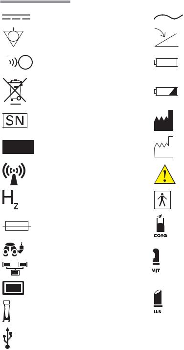
Consult operating instructions.
Caution or warning to consult accompanying documents to avoid patient or operator hazard.
110017276EN Rev. B |
Operator’s Manual Preface-3 |
Preface
Direct Current
Equipotential
Ground
Remote Control Reception Indicator
(Foot Control On/TruLink®
Customer Support Network Access)
Dispose of Properly
Serial Number
Authorised Representative
in the European Community
Non Ionizing
Electromagnetic
Radiation
Frequency in Hertz
Fuse
Microscope Camera
Ethernet
Monitor
Stellaris® PC
Vision Enhancement System.
Alternating Current
Foot Control
Battery
Battery Condition Indicator
Manufacturer
Date of Manufacture
Caution: Consult
Accompanying Documents
Type BF Applied Part
Coagulation
High Speed Vitrectomy
Ultrasound
|
Ω |
Ohms |
USB |
VA |
Volt Amps |
|
A |
Amperes |
Preface-4 Operator’s Manual |
110017276EN Rev. B |
|
Preface |
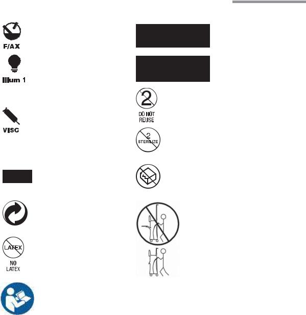
Posterior Functions |
|
Fluid/Air Exchange |
EtO gas sterilized |
Illumination |
Gamma Irradiation Sterilized |
|
Do Not Reuse |
Viscous Fluid Control |
|
|
Do Not Re-Sterilize |
21CFR 801.109(b) |
|
Caution: Federal (USA) |
|
law restricts this device to |
Do Not Use If Damaged |
sale by or on the order of a |
|
physician |
|
Member Green Dot Scheme |
|
|
Transport Symbol. |
|
See page 1-30. |
No Latex |
|
Caution: Consult |
|
Accompanying Documents |
|
110017276EN Rev. B |
Operator’s Manual Preface-5 |
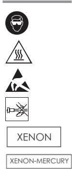
Preface
Always wear eye protection or face mask when installing or removing the lamp
Warning: Hot surface
Electrostatic-sensitive device
Never touch the silica glass bulb of the lamp with bare hands
Xenon
Xenon-Mercury
Preface-6 Operator’s Manual |
110017276EN Rev. B |
Contents
1.Getting Started
2.1. |
Components Shipped with the System..................................................................................................... |
1-2 |
2.2. |
Connections and Setup ............................................................................................................................ |
1-2 |
2.3. |
System Description.................................................................................................................................. |
1-5 |
2.4. |
Setting UpYour System ........................................................................................................................... |
1-6 |
2.5. |
Starting a New Procedure ...................................................................................................................... |
1-15 |
2.6. |
UsingYour System in Surgery ............................................................................................................... |
1-21 |
2.7. |
Concluding a Surgical Procedure........................................................................................................... |
1-23 |
2.8. |
Shutting Down the System..................................................................................................................... |
1-27 |
2.9. |
Power Interruptions ............................................................................................................................... |
1-27 |
2.10. |
MovingYour System to Another Location............................................................................................. |
1-28 |
2.11. |
System Components .............................................................................................................................. |
1-29 |
2.12. |
Foot Control........................................................................................................................................... |
1-38 |
2.13. |
Illumination Function ............................................................................................................................ |
1-59 |
2.14. |
Multimedia Center (MMC) (optional)................................................................................................... |
1-62 |
2.User Interface
3.1. Posterior & Combined Domain Interface Controls.................................................................................. |
2-1 |
|
3.2. Posterior and Combined Domain Surgical Information More Settings Screens ...................................... |
2-7 |
|
3.3. Posterior and Combined Domain Surgical Screen Layouts ................................................................... |
2-34 |
|
3.4. |
CustomizingYour System Settings ........................................................................................................ |
2-40 |
3.5. Anterior Domain Basic Interface Controls ............................................................................................ |
2-40 |
|
3.6. Anterior Domain Surgical More Settings Screens ................................................................................. |
2-46 |
|
3.7. Anterior Domain Surgical Screen Layout.............................................................................................. |
2-67 |
|
3.8. |
CustomizingYour System Settings ........................................................................................................ |
2-75 |
3.Customizing Your System
4.1. |
Manage Settings ...................................................................................................................................... |
3-3 |
4.2. |
Surgeon Level Settings ............................................................................................................................ |
3-9 |
4.3. |
Manage Surgeon Files ........................................................................................................................... |
3-14 |
4.4. |
System Setup ......................................................................................................................................... |
3-18 |
4.5. |
System Configuration ............................................................................................................................ |
3-22 |
4.6. |
System Calendar.................................................................................................................................... |
3-22 |
4.7. TruLink® Customer Support Network .................................................................................................. |
3-24 |
|
4.8. |
Customization Levels ............................................................................................................................ |
3-27 |
110017276EN Rev. B
4.Detailed Reference
5.1. |
Advanced Vacuum System Fluidics......................................................................................................... |
4-1 |
5.2. |
Posterior Functions.................................................................................................................................. |
4-5 |
5.3. |
Anterior Functions................................................................................................................................. |
4-29 |
5.4. Coagulation Function (Posterior & Anterior Modes)............................................................................. |
4-46 |
|
5.5. |
Combined Domain................................................................................................................................. |
4-50 |
5.Cleaning and Sterilization Requirements
6.1. |
Routine Cleaning ..................................................................................................................................... |
5-1 |
6.2. |
Bipolar Coagulation Accessories............................................................................................................. |
5-2 |
6.3. Irrigation and Irrigation/Aspiration Handpieces...................................................................................... |
5-3 |
|
6.4. |
Ultrasound Handpiece and Accessories ................................................................................................... |
5-6 |
6.5. Special Instructions for United Kingdom Users..................................................................................... |
5-11 |
|
6.6. |
Cleaning the MMC ................................................................................................................................ |
5-14 |
6.Troubleshooting
7.1. |
User Troubleshooting .............................................................................................................................. |
6-1 |
7.2. |
Power Issues ............................................................................................................................................ |
6-1 |
7.3. Error and Warning Messages ................................................................................................................... |
6-3 |
|
7.4. |
Troubleshooting the MMC .................................................................................................................... |
6-19 |
7.5. System Configurations, Modules, Accessories and Packs ..................................................................... |
6-20 |
|
7.Service and Warranty
8.1. |
Service Information ................................................................................................................................. |
7-1 |
8.2. |
Environmental Protection ...................................................................................................................... |
7-10 |
8.3. |
Warranty Information ............................................................................................................................ |
7-10 |
8.Specifications
9.1. Environmental and Physical Specifications |
............................................................................................. 8-1 |
|
9.2. |
Primary System Specifications ................................................................................................................ |
8-8 |
9.3. |
System Labels........................................................................................................................................ |
8-18 |
9.Glossary
110017276EN Rev. B
1 Getting Started
Getting Started
This chapter is for people who have used this type of ophthalmic vision enhancement system before and want to use the system without reading large portions of the manual. It also provides information on setting up your Stellaris® PC Vision Enhancement System and making the necessary connections.
DANGER: |
Do not use this device in the presence of flammable anaesthetics. |
WARNING: Implantable defibrillators present a risk of injury if triggered by a fibrillatory event during intraocular surgery, due to involuntary motion by the patient. Patients being considered for intraocular procedures must be questioned to determine if they have such a device and, if so, the defibrillator manufacturer must be consulted to determine the appropriate action.
WARNING: Electromagnetic interaction between the phacoemulsification (phaco) handpiece and an implanted cardiac pacemaker is unlikely, but cannot be ruled out. Patients should be questioned to determine if they have such an implant and, if so, the manufacturer of the implant should be consulted to determine the proper course of action.
WARNING: All external wiring must be in accordance with local electrical code requirements and NEC Class II signaling system twisted wire with outer shield. The wire length must not exceed 20 meters (60 feet). The wire gage must be 26 AWG to 12 AWG gage, with ends stripped from 9 mm to 10 mm (3/8 inch). At no point should the wire be untwisted more than 5 cm (2 inches).
WARNING: Patient not to come in contact with earthing metal parts.
WARNING: Avoid skin-to-skin contact.
WARNING: Grounding reliability can only be achieved when the equipment is connected to an equivalent receptacle marked “Hospital Only” or “Hospital Grade.”
110017276EN Rev. B |
Operator’s Manual 1-1 |

1 Getting Started
WARNING: |
To avoid risk of electric shock, this equipment must only be connected to a supply mains with |
|
protective earth. |
Note: |
Preventative scheduled maintenance is recommended once a year to insure that the |
|
Stellaris® PC Vision Enhancement System meets it optimum performance, reliability |
|
and safety standards set by the manufacturer. The maintenance shall be done by a |
|
Bausch + Lomb certified individual only. |
1.1. Components Shipped with the System
Before unpacking, inspect all packages for damage. Report any damage from shipping to the carrier. Before discarding packaging material, assure all parts are accounted for. Smaller parts may be attached to packing materials.
Standard components shipped with the system include:
•System Main Console
•Foot Control with Battery
•Foot Control Wall Charger
•Extra Foot Control Battery
•Foot Control Backup cable
•Operator’s Manual (CD)
•System Power Cord
•Mayo Tray
•Foot Control Battery Charging Cradle
•Air Hose
•Zero Level Bottle Hanger
1.2. Connections and Setup
WARNING: For optimum aspiration and reflux performance, the patient’s eye must be at the same level as the Stellaris® PC Vision Enhancement System aspiration port. If this is not possible, use the patient eye level offset feature in the programming screen.
1-2 Operator’s Manual |
110017276EN Rev. B |
1 Getting Started
Note: |
The out-of-factory Wireless System Setup is Disabled. Performing a software upgrade |
|
will also reset the Wireless System Setup to Disabled. To setup wireless operation, see |
|
Wireless Foot Control Operations System Setup on page 1-46. |
The Stellaris® PC Vision Enhancement System is pre-configured at the factory to minimize setup and installation requirements.
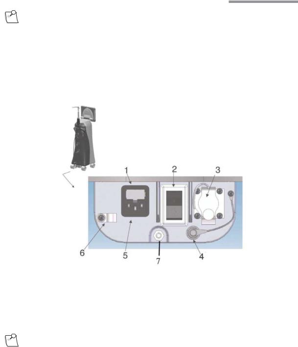
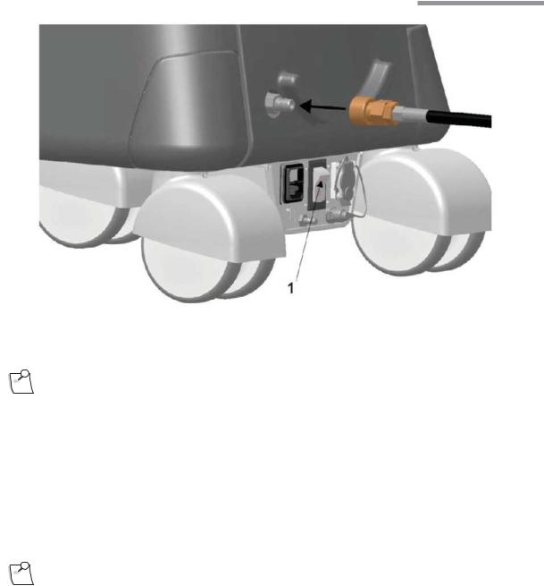
The power cable, Foot Control and Ethernet connections are located at the lower rear of the system.
Figure 1.1. Lower Rear of System.
1.Fuse Holder.
2. Main Power Switch, disconnects system from mains voltage. See IEC 60601-1, paragraph 8.6.7 3. Ethernet Port. 4. Foot Control Backup Cable Port.
5. Power Cord Input. 6. Power Cord Retention Clip. 7. Potential Equalization Connector.
Note: Turning off the Main Power Switch will disconnect the system from mains.
110017276EN Rev. B |
Operator’s Manual 1-3 |

1 Getting Started
Foot Control
The Foot Control can use either wired or wireless communication. The first time the Stellaris® PC Vision Enhancement System is used, you must use the wired connection to establish communication between the Foot Control and the Stellaris® PC Vision Enhancement System.
For wired communication, connect the Foot Control backup cable from the back of the Foot Control to the lower rear of the Stellaris® PC Vision Enhancement System.
Ethernet Cable (optional)
The Ethernet cable connection only applies to a Stellaris® PC Vision Enhancement System with TruLink® Customer Support Network enabled, when you intend to upload system information to the Bausch + Lomb Global Service Support server. No Ethernet cable is supplied with the system.
If you plan to use the TruLink® Customer Support Network, connect an Ethernet cable from the back of the Stellaris® PC Vision Enhancement System to the wall network port before powering up the system, and disconnect it after the system is powered down.
When the Ethernet cable is not in use, install the attached protective cap into the open socket.
Compressed Air Connection
Connect the external air hose to the rear of the system as shown, and then to an appropriate air source.
1-4 Operator’s Manual |
110017276EN Rev. B |

1 Getting Started
|
Figure 1.2. Back bottom of system. |
Note: |
The system requires filtered medical grade air or medical grade nitrogen, at 72.5 to |
|
100 psig (500 kPa to 690 kPa or 5.0 to 6.9 bar) and a flow rate of 2.25 SCFM |
|
(63.7 SLPM). |
1.3. System Description
The Stellaris® PC Vision Enhancement System has a modular design which enables it to be easily upgraded to take advantage of advances in technology. The system consists of a main housing unit which contains a user interface screen and the surgical modules, and a Foot Control, infrared remote control (for anterior application only, optional accessory). Handpieces, packs and other accessories are supplied separately.
110017276EN Rev. B |
Operator’s Manual 1-5 |

1 Getting Started
Figure 1.3. Stellaris® PC Vision Enhancement System
Your Stellaris® PC Vision Enhancement System was designed to be easily upgraded to take advantage of future technology evolution. It includes an 19 inch, 5:4 aspect ratio color touch screen display which is the primary interface between you and your system. The display console may be tilted 10 degrees forward and 15 degrees back, and swiveled 90 degrees to the right or left. The brightness of the display is controlled through the A/V More Screen (see page2-28).
At the bottom of the screen is an infrared receiver which interfaces with the remote control.
The computer system includes both audio and visual capabilities, which provide warning messages, alarms, and other audio indications, as well as allowing you to view setup screens surgical settings, and video from a microscope camera. The volume is adjustable via the touch screen spin buttons on the A/V More Screen.
Two USB ports on the back of the display allow you to save, load, and transfer your customized settings between systems.
A single port on the front of system provides filtered atmospheric air for both Fluid/Air Exchange (F/AX) and Air Forced Infusion (AFI) for posterior and combined surgery.
There are two air outputs built into the system, to provide filtered atmospheric air for anterior and posterior surgeries. The front port provides air for both Fluid/Air Exchange and Air Forced Infusion in posterior and
1-6 Operator’s Manual |
110017276EN Rev. B |

1 Getting Started
combined surgery. The port near the IV Pole on the back of the system provides air for Pressurized Infusion (PI) in anterior surgery.
The system can be set for either gravity infusion or infusion using pressurized air (AFI and PI, respectively) through the Infusion Tab of the More Settings Screen or through the programming interface (see Chapter 3).
Both air output ports have lighted rings surrounding them. The ring light will be solidly lit if that function is active and within correct pressure range. If the pressure moves outside of the specified range, the ring will begin blinking. If the pressure remains outside the set range, an error message will appear on the screen.
1.4. Setting Up Your System
DANGER: |
Do not use in the presence of flammable anaesthetics, disinfectants, aerosol sprays, or in an |
|
oxygen rich atmosphere. |
WARNING: This system should only be operated by personnel who have been trained and are qualified to use this system.
WARNING: Do not manually force the IV Pole downward if the system is on.
WARNING: Do not modify the pole height or manually force the pole height, as this could cause an incorrect indication of the bottle height, leading to patient injury.
WARNING: When using gravity infusion, the ophthalmic irrigation source shall be at or above the patient’s eye level to avoid patient injury.
CAUTION: Do not block air vents.
Note: |
Do not add unapproved accessories that modify the effective IV pole height. |
110017276EN Rev. B |
Operator’s Manual 1-7 |

1 Getting Started
Before the first use of the Stellaris® PC Vision Enhancement System, connect the Foot Control to the system with the Foot Control backup cable provided with the system.
The following pages contain an overview for setup and use of your Stellaris® PC Vision Enhancement System in a typical cataract surgery. This information is intended for use by someone who is already familiar with this type of system.
Turning System On
Plug the power supply cord into the wall. Connect the compressed air hose to the system.
If desired, connect the Ethernet cable to the port at the bottom of the Stellaris® PC Vision Enhancement System, and the other end to the hospital network port. If you have the optional MMC system, this cable should be connected to the MMC, and the MMC in turn connected to the hospital network port. Refer to page 1-39 for detailed MMC setup instructions.
Turn on the switch at the bottom of the system console.
WARNING: Ensure that the power cord is routed away from traffic areas to prevent accidental disconnection or tripping hazards.
CAUTION: Do not turn this switch off until the system has been properly shut down.
CAUTION: Do not disconnect system from power while in use.
Connect the air supply to the back bottom of the system.
CAUTION: |
Observe system diagnostic messages when powering up system for first use each day and take |
|
appropriate action if required. Also observe first cassette priming or calibration, phaco/frag |
|
handpiece tuning and/or vitrectomy handpiece testing for correct completion. |
1-8 Operator’s Manual |
110017276EN Rev. B |
1 Getting Started
|
Figure 1.4. Back bottom of system. |
|
1.Main Power Switch. |
Note: |
The system requires filtered medical grade air or medical grade nitrogen, at |
|
72.5 to 100 psig (500 to 690 kPa or 5.0 to 6.9 bar) and a flow rate of 2.25 SCFM |
|
(63.7 SLPM). |
Press the power button on the front of the system, and wait for the screen to come on and the animation to finish. The front power switch is brighter when the system is off, and dims when you turn the system on.
The Stellaris® PC Vision Enhancement System performs a self-check each time the power is turned on. The system automatically checks its configurations for any changes since the last time it was turned on.
Note: |
When turning the system on for the fi rst use of the day, pay close attention to any warning messages |
|
that appear on the screen and address any issues. |
After the Foot Control has been synchronized to the specific Stellaris® PC Vision Enhancement System. (See page 1-40), you may use wireless communication.
110017276EN Rev. B |
Operator’s Manual 1-9 |

1 Getting Started
Note: |
The out–of- factory Wireless System Setup is “Disabled”. Software upgrade will also |
|
reset the Wireless System Setup to “Disabled”. See System Setup Instructions on |
|
page 1-46 to configure Foot Control to wireless operation. |
If you are going to use the Foot Control in wireless mode, ensure the Foot Control battery is charged, then hold down any button on the Foot Control until the green ready light comes on, indicating that communication has been initiated. This light will turn solid green when full communications have been established.
When the system check is completed following system power-up, the Splash screen will appear (See Figure 1.5 on page 1-10).
Note: |
Following system shut down, wait a minimum of 15 seconds before restarting the |
|
system. The system is fully shut down after the front panel power button light changes |
|
from dim to bright. |
Figure 1.5. Opening Splash Screen.
1-10 Operator’s Manual |
110017276EN Rev. B |
1 Getting Started
Once the software has finished loading, the Select Procedure screen will appear as shown below.
Figure 1.6. Select Procedure Screen.
A Select Surgeon Screen (as shown in Figure 1.7 on page 1-12) will appear when you select any type of procedure from the Select Procedure Screen.
If your system is programmed to default to either the Anterior Domain, Posterior Domain or the Combined Domain, the Select Procedure Screen will not appear, and the system will move directly to the Select Surgeon Screen, as shown in Figure 1.7 below.
110017276EN Rev. B |
Operator’s Manual 1-11 |
1 Getting Started
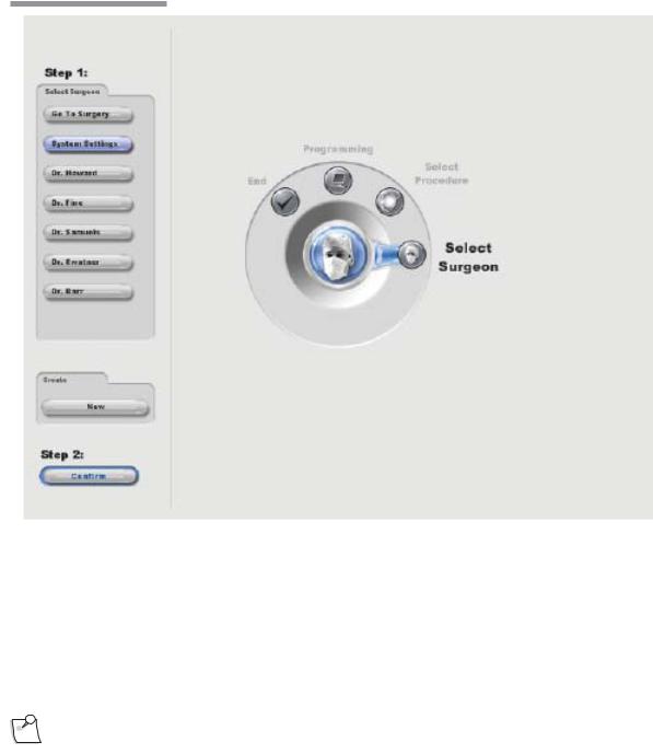
Figure 1.7. Select Surgeon Screen.
Select Surgeon
Selecting Go To Surgery option will advance the system to the Setup Screen, using the system’s default parameters.
Touch the name of a surgeon on the list to highlight it. Then select Confirm to load the parameters for that surgeon and advance to the Setup Screen.
Note: |
If the Confirm button is not active, this indicates one or more modules were not |
|
detected in the system and further operation is not allowed. |
To set up default parameters for a new surgeon instead of using an existing surgeon’s file, select Create New. This will allow you to setup a file for a new surgeon, using parameters from an existing surgeon as a template.
1-12 Operator’s Manual |
110017276EN Rev. B |
1 Getting Started
Setup Screen
The Setup Screen allows you to set certain procedure parameters, and prepare the system for surgical procedures.
The Open Pack/Insert Cassette option will be highlighted when you initially see this screen.
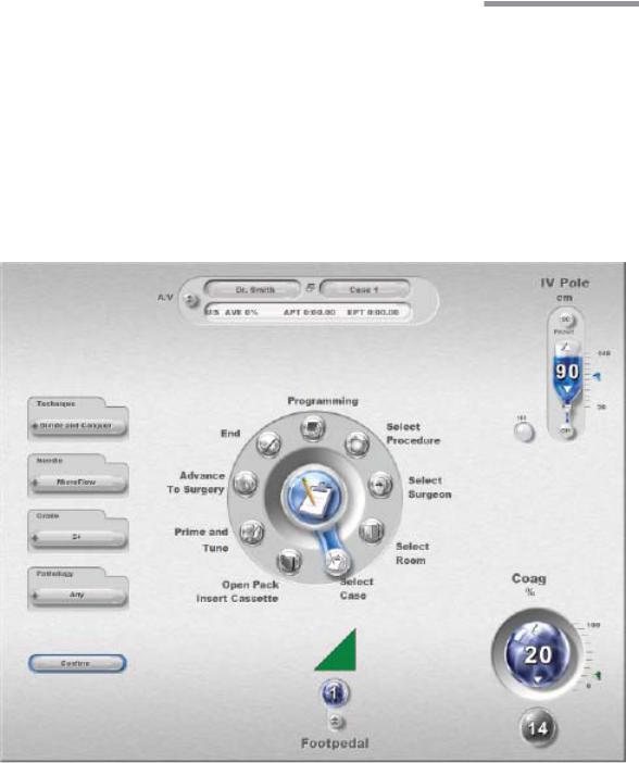
If desired, select Select Room (Anterior Only) and choose the case number, number of operating rooms being used by the surgeon, and the particular operating room to be used.
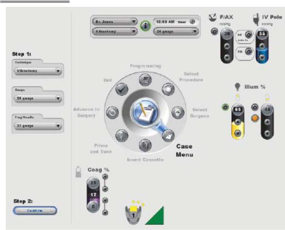
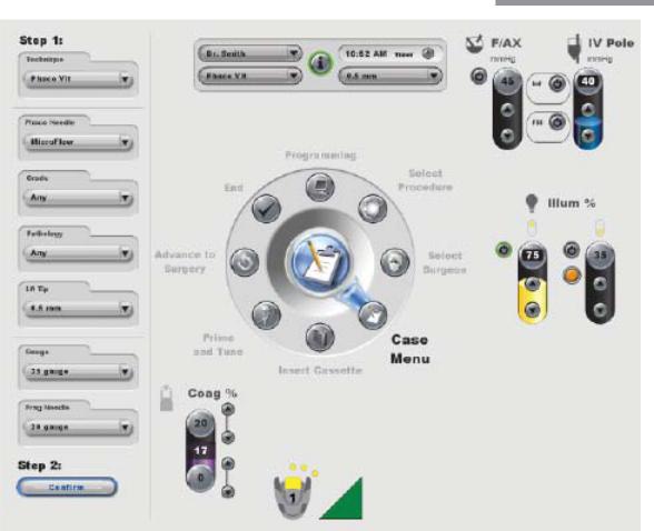
If desired, select Select Case (Anterior) or Case Menu (Posterior and Combined) and choose the specific technique, needle, grade and pathology (Anterior Domain) or vitrectomy gauge, fragmentation needle (Posterior Domain) for the current procedure. The appearance of this screen will differ for the three possible domains, as shown in Figure 1.8.
Figure 1.8. Anterior Domain Select Case Screen.
110017276EN Rev. B |
Operator’s Manual 1-13 |
1 Getting Started
Figure 1.9. Posterior Domain Case Menu Screen.
1-14 Operator’s Manual |
110017276EN Rev. B |
1 Getting Started
Figure 1.10. Combined Domain Case Menu Screen.
Advance to the open pack step by selecting Open Pack Insert Cassette (Anterior Domain) or Insert Cassette (Posterior or Combined Domain) from the clock menu.
110017276EN Rev. B |
Operator’s Manual 1-15 |

1 Getting Started
1.5. Starting a New Procedure
The Stellaris® PC Vision Enhancement System is user-friendly, and will highlight whichever step is next in a typical procedure. The steps shown on the display screen will vary slightly depending on which optional
features are installed on your machine. On-screen instructions take precedence over information in this manual.
WARNING: Before beginning a procedure, ensure that there is sufficient volume of irrigation solution for the entire procedure.
Note: |
Ensure tube set connection is secure when connecting to the handpiece and system. |
1. Set up the sterile field.
Open the disposable pack and drop contents onto a sterile surface.
Note: |
Make sure to use the proper pack for the mode you are using. Packs will not work |
|
for other modes. The packs are color coded. Anterior packs are green and/or light |
|
blue. Posterior Packs and Combined Packs are color-coded by needle gauge - 20 g is |
|
black, 23 g is green, and 25 g is blue. |
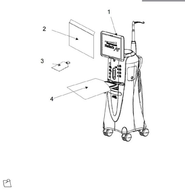
Attach the sterile screen drape by placing the drape over the top of the Stellaris® PC Vision Enhancement System screen and secure with the adhesive strip to top, not the front, of the display as shown in the illustration below.
1-16 Operator’s Manual |
110017276EN Rev. B |
1 Getting Started
Figure 1.11. Schematic diagram of sterile draping.
1. Adhere screen drape on the top of the screen panel. 2. Screen drape. 3. Anterior Remote control drape. 4.Mayo Tray drape.
2. Setup Fluid Collection System
Note: |
Ensure sufficient volume of irrigation solution is available for the procedure. The |
|
level should be monitored during the procedure. |
Insert the fluidics cassette into the slot on the front of the system and hold until it is automatically captured by the system. The cassette housing backlight will stop blinking and remain on when the system captures the cassette.
The system will automatically conduct a vacuum sensor and calibration check. Wait until the progress bar shows successful completion to proceed. If the system does not pass, corrective actions will be suggested. Following the successful cassette check, the screen will automatically advance to the Prime and Tune steps.
110017276EN Rev. B |
Operator’s Manual 1-17 |

1 Getting Started
3.Connect the proper accessories to the system for an Anterior, Posterior, or Combined procedure.
Note: |
If you are using a vented Air Forced Infusion (AFI) pack, make sure to connect the |
|
Fluid/Air Exchange filter to the F/AX port on the front of the machine. |
Detailed setup instructions for each configuration are provided in Chapter 4. Use the following list to navigate to the appropriate page and surgical setup instructions for the desired configuration.
Posterior Domain -
•Vitrectomy - See page4-7
•Illumination - See page 4-12
•Fluid/Air Exchange - See page 4-19
•Viscous Fluid Injection - See page 4-24
•Viscous Fluid Aspiration - See page 4-25
•Linear Fluid Injection, Linear Vacuum - See page 4-27
•Fragmentation - See page 4-28
Anterior Domain -
•Irrigation/Aspiration - See page4-31
•Phacoemulsification - See page 4-37
•Planned Anterior Vitrectomy - See page 4-40
•Unplanned Anterior Vitrectomy - See page 4-41
Coagulation -
•Fixed Coagulation - See page 4-47
•Linear Coagulation - See page 4-48
Combined Domain - See page 4-50
Note: |
Fragmentation uses the same power connection as the ultrasound handpiece. Only |
|
one function can be used at a time. |
Note: |
If a linear coagulation in set up is enabled or a Foot Control button is programmed |
|
for coagulation, begin by plugging in the coagulation cord. |
For on-screen instructions, select Show Me Steps from the Prime and Tune Screen and a tabbed screen will appear, detailing the required steps and showing animations of how to perform each step.
1-18 Operator’s Manual |
110017276EN Rev. B |

1 Getting Started
WARNING: The animations illustrate the steps but do not represent sterile technique.
4. Prime and Tune
Note: |
The system will not provide feedback as to whether or not fluid is present during |
|
priming. Inspect tubing and confirm that it is filled with fluid and free of bubbles |
|
after each Prime and Tune. Repeat the priming process if the tubing is not adequately |
|
filled with fluid. |
When the cassette has been inserted and captured by the machine, and all accessories, tubing and handpieces have been connected, the system is ready for Prime and Tune. To proceed to the Prime and Tune phase, select the appropriate options for the domain in which you are operating. Available options are described below.
For Posterior Domain:
•Select the Easy Prime button from the Prime and Tune screen to fill the left and right tubing with BSS solution, and then perform a test of the pneumatic cutter. During this process, the gravity feed infusion I/V pole will raise to 100 cm or lower if maximum ceiling height is set lower than 100 cm
for the anterior. In the posterior/combined domains, I/V pole will raise to the maximum ceiling height programmed for the system. With the air pressured infusion, the pressure will raise to 73 mmHg for anterior domain and 103 mmHg for posterior/combined domains.
•Select the Prime/Test Vit button to activate the vacuum on right side aspiration line and test the pneumatic vitrectomy function. The handpiece tip must be submerged in BSS during this process. After the line has been primed, this button will become Test Vit, which will activate the cutter test without aspiration.
•Select the Prime/Tune U/S button to activate aspiration on the left line and tune the fragmentation handpiece. The electric connector on the fragmentation handpiece must be inserted into the
Stellaris® PC Vision Enhancement System and the tip submerged in BSS before this option is selected. After the line has been primed, this button will become Tune U/S, which will activate a shorter cycle of aspiration and tuning.
•Select the Prime/Aux button to activate aspiration to fill the left aspiration line with BSS. After the first use, subsequent priming cycles will be slightly shorter.
110017276EN Rev. B |
Operator’s Manual 1-19 |

1 Getting Started
For Combined Domain:
•Select the Easy Prime button from the Prime and Tune screen to fill the left and right tubing with BSS solution, and then perform a test of the pneumatic cutter. During this process, the gravity feed infusion I/V pole will raise to 100 cm or lower if maximum ceiling height is set lower than 100 cm
for the anterior. In the posterior/combined domains, I/V pole will raise to the maximum ceiling height programmed for the system. With the air pressured infusion, the pressure will raise to 73 mmHg for anterior domain and 103 mmHg for posterior/combined domains.
•Select the Prime/Test Vit button to activate the vacuum on right side aspiration line and test the pneumatic vitrectomy function. The handpiece tip must be submerged in BSS during this process. After the line has been primed, this button will become Test Vit, which will activate the cutter test without aspiration.
•The operation of the Prime/Tune U/S button differs, depending on which ultrasound handpiece is connected to the system.
•Fragmentation Handpiece: Select the Prime/Tune U/S button to activate aspiration on the left line and tune the fragmentation handpiece. The electrical connector on the fragmentation handpiece must be inserted into the Stellaris® PC Vision Enhancement System and the tip submerged in BSS before this option is selected. After the line has been primed, this button will become Tune U/S, which will activate a shorter cycle of aspiration and tuning.
•Ultrasound handpiece: Select the Prime/Tune U/S button to initiate priming of the irrigation and left aspiration line, followed by tuning of the ultrasound handpiece and a vacuum test. During this process, the IV bottle will be raised to 100 cm or the system will use a pressure of 73 mmHg if AFI is used. The irrigation line and the aspiration line need to be connected to the ultrasound handpiece with the test chamber attached to the tip of the ultrasound handpiece. After the line has been primed, this button will change to Tune U/S which will activate a shorter cycle of aspiration and tuning without the vacuum test.
•Select the Prime/Aux button to activate aspiration to fill the left aspiration line with BSS. After the line has been primed, subsequent priming cycles will be slightly shorter.
For Anterior Domain:
•Select the Prime and Tune button from the Prime and Tune Screen to initiate priming of the irrigation and left aspiration line, followed by tuning of the ultrasound handpiece and a vacuum test. During this process, the IV bottle will be raised to 100 cm or the system will use a pressure of 73 mmHg if AFI is used. The irrigation line and the aspiration line need to be connected to the ultrasound handpiece with the test chamber attached to the tip of the ultrasound handpiece. After the line has been primed, this button will change to Tune Only which will activate a shorter cycle of aspiration and tuning without the vacuum test.
•Select the Prime Only button from the Prime and Tune Screen to initiate priming of the irrigation and left aspiration line, followed by a vacuum test. The irrigation line and the aspiration line need to be connected to the ultrasound handpiece with the test chamber attached to the tip of the ultrasound handpiece. During this process, the IV bottle will be raised to 100 cm or the system will use a pressure of 73 mmHg if AFI is used. After the line has been primed, the button will activate a shorter cycle of aspiration without the vacuum test.
•Select the Pneumatic Vit test to activate aspiration and a test of the pneumatic cutter.
•In the anterior domain, the remote control can be used to activate functions in the “Prime and Tune” window of the setup screen. The remote control UP/DOWN buttons are used to move the arrow and select options in the “Prime and Tune” window:
1-20 Operator’s Manual |
110017276EN Rev. B |
 Loading...