


Operator’s Manual

© Bausch & Lomb Incorporated. No part of this publication may be copied, photocopied, reproduced, translated, or reduced to any electronic medium or machine readable form, in whole or in part, without thepriorwrittenconsentofBausch&LombIncorporated,Rochester,NY14609USA.™/®aretrademarksofBausch&LombIncorporatedoritsaffiliates.Allotherbrand/productnamesaretrademarksoftheirrespectiveowners.
Bausch & Lomb Incorporated |
Bausch & Lomb Incorporated |
Manufacturing site: |
|
One Bausch & Lomb Place |
Bausch & Lomb Incorporated |
110017243EN Rev. H BL3153EN |
|
Rochester, NY 14609 USA |
106 London Road, Kingston upon Thames, KT2 6TN, UK |
3365 Tree Court Industrial Blvd., St. Louis, MO 63122 |

Preface
Indications for Use
The Bausch + Lomb Stellaris® Vision Enhancement System is designed for use in anterior segment surgeries. It provides capabilities for phacoemulsification, irrigation/aspiration, bipolar coagulation, and vitrectomy operations.
WARNING: Use only Bausch + Lomb approved disposable packs, tubing sets and Bausch + Lomb handpieces designated for use with this system Safety may be degraded if accessories not meant for the system are connected.
User Profile
The Bausch + Lomb Stellaris® Vision Enhancement System is intended for use only by qualified physicians and nurses.
Contraindications
Use of accessories not designated by Bausch + Lomb for use with this equipment may result in serious permanent patient injury, adverse surgical outcome, or damage to the equipment, which may not be covered by warranty. See page 1-1 for precautions relevant to patients with implantable defibrillators and cardiac pacemakers.
This manual contains precautions (Danger, Cautions, Warnings, Notes, etc.) throughout that should be observed when using this equipment. For safety’s sake, please heed these precautions.
Patents
The Bausch + Lomb Stellaris® Vision Enhancement System is covered by the following patents: 5,331,951; 5,370,602; 5,388,569; 5,406,503; 5,624,394; 5,795,328; 5,910,139; 5,964,746; 5,991,142; 6,045,527; 6,055,458; 6,077,272; 6,081,122; 6,083,195; 6,106,512; 6,203,516; 6,251,113; 7,168,930, 7,445,436 and 7,604,607; additional patents pending. Foreign and other patents may also apply.
Trademarks
®/™ are trademarks of Bausch & Lomb Incorporated or its affiliates.
All other brand/product names are trademarks of their respective owners.
110017243EN Rev. H |
Preface-1 |

Preface
Power Outputs
COAG |
U/S |
BF |
BF |
|
|
7.5 W |
35 W |
|
|
100 Ω |
900 Ω |
|
|
1 MHz |
28.5 kHz |
|
|
Training
Following system installation at a surgical facility, Bausch + Lomb personnel will provide on-site training to users who will operate the system. The training includes system startup, accessories and connections, priming and settings adjustment consistent with the instructions provided in this user manual. Subsequent training is provided for new staff, when the system is upgraded, or as requested by the facility.
Manual Concept
Bausch + Lomb designs manuals to give you the information you need when you need it, and we don’t want you to have to search to find it.
This manual is organized so that in the first chapter you will find enough information to quickly get up and running, and get answers to general questions about the Stellaris® Vision Enhancement System. We have included plenty of pictures so you can grasp concepts quickly. Be sure to read Chapter 2 to become familiar with the Graphical User Interface and the Foot Control. These are your connections to operate the system. Chapter 3 describes information on how to customize the system to suit your particular needs. Chapter 4 has detailed information about each function and feature, how to set up the function and its associated disposables, and how to interact with each function. Chapter 5 provides cleaning and sterilization information. These chapters are meant to serve as a reference to questions of a more technical nature. Chapter 6 through Chapter 8 contain information that you may rarely need, such as unpacking, installing modules, system check-out, meanings
of error messages, service information, and system specifications. Make sure that you read and follow all safety precautions set forth in this manual. Information presented in this manual relating to surgical procedures is a suggestion only, and does not constitute any warranty of fitness or claim of responsibility, or undertaking of liability resulting from any surgical techniques practiced. The physician is ultimately responsible for determining the appropriate procedure for each patient.
Note: The user interface screens displayed in this manual copy may appear different than what is on your system depending on the configuration. While the information is the same, the depiction may change. The illustrations should not be used in place of the instructions in the manual.
Preface-2 |
110017243EN Rev. H |

Preface
Symbols and Notes
The following are general definitions of the symbols and precautions used on this equipment and in this manual.
DANGER: |
Calls attention to an operating procedure, practice, or condition, which if disregarded or |
|
incorrectly performed, could result in imminent explosion hazard and risk of death or serious |
|
injury. |
WARNING: Calls attention to an operating procedure, practice, or condition, which if disregarded or incorrectly performed, could result in serious and/or permanent injury to personnel and/or patients.
CAUTION: Calls attention to an operating procedure, practice, or condition, which if disregarded or incorrectly performed, could result in damage to the product and/or equipment.
Note: Calls attention to an operating procedure, practice, or condition providing essential information.
Consult operating instructions.
Caution or warning to consult accompanying documents to avoid patient or operator hazard.
110017243EN Rev. H |
Preface-3 |

Preface
Direct Current
Equipotential
Ground
Remote Control Reception Indicator
(Foot Control On/TruLink® Access)
Dispose of Properly
Serial Number
Authorized Representative
in the European Community
Non Ionizing
Electromagnetic
Radiation
Frequency in Hertz
Fuse
Camera Recorder
Ethernet
Monitor
Stellaris®
Vision Enhancement System.
USB
Alternating Current
Foot Control
Battery
Battery Condition Indicator
Manufacturer
Date of Manufacture
Caution: Consult
Accompanying Documents
Type BF Applied Part
Coagulation

 or
or 

Pneumatic Vitrectomy

 or
or 

Ultrasound
 or
or 
ΩOhms
VA |
Volt Amps |
AAmperes
Preface-4 |
110017243EN Rev. H |

Preface
21CFR801.109(b)
Caution: Federal (US) law restricts this device to sale by or on the order of a physician
No Latex
Member Green Dot Scheme
Do Not Use if Package is Damaged
System transport information, refer to page 1-12.
Caution: Consult
Accompanying Documents
110017243EN Rev. H |
Preface-5 |

Preface
Preface-6 |
110017243EN Rev. H |
|
|
Table of Contents |
1. |
Getting Started |
|
|
||
1.1. |
System Description ................................................................................................................................ |
1-2 |
1.2. |
Setting UpYour System.......................................................................................................................... |
1-3 |
1.3. |
MovingYour System to Another Location............................................................................................ |
1-11 |
1.4. |
System Components............................................................................................................................. |
1-12 |
2. |
User Interface |
|
2.1. |
Basic Interface Controls ......................................................................................................................... |
2-1 |
2.2. |
Surgical “More Screens” ........................................................................................................................ |
2-6 |
2.3. |
Surgical Screen Layout......................................................................................................................... |
2-14 |
2.4. |
Foot Control ......................................................................................................................................... |
2-18 |
3. |
Customizing Your System |
|
3.1. |
Manage Settings ..................................................................................................................................... |
3-3 |
3.2. |
System Setup ........................................................................................................................................ |
3-18 |
3.3. |
System Configuration........................................................................................................................... |
3-21 |
3.4. |
System Calendar................................................................................................................................... |
3-22 |
3.5. |
TruLink® Remote Access .................................................................................................................... |
3-23 |
3.6. |
Customization Levels ........................................................................................................................... |
3-25 |
4. |
Detailed Reference |
|
4.1. |
Computer Unit........................................................................................................................................ |
4-1 |
4.2. |
System Console ...................................................................................................................................... |
4-2 |
4.3. |
IV Pole.................................................................................................................................................... |
4-5 |
4.4. |
Remote Control ...................................................................................................................................... |
4-6 |
4.5. |
Advanced Vacuum System Fluidics........................................................................................................ |
4-7 |
4.6. |
Advanced Flow System Fluidics .......................................................................................................... |
4-12 |
4.7. |
Irrigation/Aspiration Setup................................................................................................................... |
4-14 |
4.8. |
Vitrectomy Function............................................................................................................................. |
4-15 |
4.9. |
Ultrasound Function............................................................................................................................. |
4-20 |
4.10. |
Coagulation Function ........................................................................................................................... |
4-27 |
4.11. |
DigiFlow™ Pressurized Infusion Function .......................................................................................... |
4-30 |
110017243EN Rev. H

Table of Contents
5. Cleaning and Sterilization Requirements
5.1. Stellaris® Vision Enhancement System Routine Cleaning |
..................................................................... 5-2 |
|
5.2. |
Bipolar Coagulation Accessories............................................................................................................ |
5-3 |
5.3. Advanced Flow Fluidics Transducer ...................................................................................................... |
5-4 |
|
5.4. Irrigation and Irrigation/Aspiration Handpieces..................................................................................... |
5-5 |
|
5.5. |
Phacoemulsification Handpiece and Accessories ................................................................................... |
5-8 |
5.6. Special Instructions for United Kingdom Users ................................................................................... |
5-12 |
|
5.7. |
Cleaning the MMC ............................................................................................................................... |
5-14 |
6. |
Setup |
|
6.1. |
Setup Instructions................................................................................................................................... |
6-2 |
6.2. |
Connections and Setup ........................................................................................................................... |
6-2 |
6.3. |
Multimedia Center (MMC) (optional accessory) ................................................................................... |
6-3 |
7. |
Troubleshooting and Maintenance |
|
7.1. |
User Troubleshooting ............................................................................................................................. |
7-1 |
7.2. |
Power Issues ........................................................................................................................................... |
7-1 |
7.3. |
Informational and Warning Messages .................................................................................................... |
7-3 |
7.4. |
Troubleshooting the MMC ................................................................................................................... |
7-19 |
7.5. |
System Configurations, Modules, Accessories and Packs .................................................................... |
7-21 |
8. |
Service and Warranty |
|
8.1. |
Service Information................................................................................................................................ |
8-2 |
8.2. |
Environmental Protection..................................................................................................................... |
8-12 |
8.3. |
Warranty Information ........................................................................................................................... |
8-13 |
9. |
Specifications |
|
9.1. |
Environmental and Physical Specifications............................................................................................ |
9-1 |
9.2. |
Primary System Specifications ............................................................................................................... |
9-8 |
110017243EN Rev. H
1 Getting Started
Getting Started
This chapter is for people who have used this type of ophthalmic Vision Enhancement System before and want to use the system without reading large portions of the manual.
WARNING: Implantable defibrillators present a risk of injury if triggered by a fibrillatory event during intraocular surgery, due to involuntary motion by the patient. Patients being considered for intraocular procedures must be questioned to determine if they have such a device and, if so, the defibrillator manufacturer must be consulted to determine the appropriate action.
WARNING: Electromagnetic interaction between the phacoemulsification (phaco) handpiece and an implanted cardiac pacemaker is unlikely, but cannot be ruled out. Patients should be questioned to determine if they have such an implant and, if so, the manufacturer of the implant should be consulted to determine the proper course of action.
WARNING: Patient not to come in contact with earthing metal parts.
WARNING: Avoid skin-to-skin contact.
WARNING: Grounding reliability can only be achieved when the equipment is connected to an equivalent receptacle marked “Hospital Only” or “Hospital Grade.”
WARNING: To avoid risk of electric shock, this equipment must only be connected to a supply mains with protective earth.
110017243EN Rev. H |
Operator's Manual 1-1 |
1 Getting Started
1.1. System Description
The Stellaris® Vision Enhancement System has a modular design which enables it to be upgraded to take advantage of advances in technology. The system consists of a main housing unit which contains a user interface screen and the surgical modules, and a Foot Control, infrared remote control, handpieces, and other accessories.
Note: Do not use StellarisPC Vision Enhancement System posterior or combined packs on a Stellaris system.
IV Pole
User Interface Screen 
System Switch “ON/OFF”
|
|
|
|
|
|
|
|
|
|
|
|
|
Pneumatic Anterior |
|
|
|
|
|
|
|
|
|
|
|
|
|
|
|
|
|
|
|
|
|
|
|
|
|
|
|
Vit Acuator |
|
|
|
|
|
|
|
|
|
|
|
|
||
Handpiece Connectors |
|
|
|
|
|
|
|
|
|
|
|
|
Expansion Space |
|
|
|
|
|
|
|
|
|
|
|
|
||
|
|
|
|
|
|
|
|
|
|
Fluidic Module |
|||
Surgical Tray |
|
|
|
|
|
|
|
|
|
||||
|
|
|
|
|
|
|
|
|
|||||
|
|
|
|
|
|
|
|
|
|
|
|
||
|
|
|
|
|
|
|
|
|
|
|
|
||
Drawer |
|
|
|
|
|
|
|
|
|
|
|
||
|
|
|
|
|
|
|
|
|
|
|
|
||
|
|
|
|
|
|||||||||
One-Touch Wheel Locking
1-2 Operator's Manual |
110017243EN Rev. H |

1 Getting Started
1.2. Setting Up Your System
DANGER: |
Do not use in the presence of flammable anaesthetics, disinfectants, aerosol sprays, or in an |
|
oxygen rich atmosphere. |
WARNING: This system should only be operated by personnel who have been trained and are qualified to use this system.
Note: Do not add unapproved accessories that modify the effective IV pole height.
WARNING: Do not manually force the IV Pole downward if the system is on.
WARNING: Do not modify the pole height or manually force the pole height, as this could cause an incorrect indication of the bottle height and patient injury.
WARNING: When using gravity infusion, the ophthalmic irrigation source shall be at or above the patient’s eye level to avoid patient injury.
Before the first use of the Stellaris® Vision Enhancement System, connect the Foot Control as described on page6-3.
The following pages contain an overview for setup and use of your Stellaris® Vision Enhancement System in a typical cataract surgery. This information is intended for use by someone who is already familiar with this type of system.
110017243EN Rev. H |
Operator's Manual 1-3 |

1 Getting Started
Surgical Drape Setup
Attach the sterile screen drape by placing the drape over the top of the Stellaris® Vision Enhancement System screen and secure with the adhesive strip to top, not the front, of the display as shown in the illustration below.
Apply Screen Drape Here
Screen Drape
Remote Control Drape
Tray Drape
Turning System On
Plug the power supply cord into the wall.
If desired, connect the Ethernet cable to the port at the bottom of the Stellaris® Vision Enhancement System, and the other end to the hospital network port. If you have the optional MMC system, this cable should be connected to the MMC, and the MMC in turn connected to the hospital network port.
Turn on the switch at the bottom of the system console.
CAUTION: Do not turn this switch off until the system has been properly powered down.
CAUTION: Do not disconnect system from power while in use.
1-4 Operator's Manual |
110017243EN Rev. H |

1 Getting Started
Figure 1.1. Lower Rear of System.
1. Fuse Holder.
2. Main Power Switch, disconnects system from mains voltage. See IEC 60601-1, paragraph 8.6.7 3. Ethernet Port. 4. Foot Control Backup Cable Port.
5. Power Cord Input. 6. Power Cord Retention Clip. 7. Potential Equalization Connector.
Note: Turning off the Main Power Switch will disconnect the system from mains.
Press the power button on the front of the system, and wait for the screen to come on and the animation to finish. The front power switch is brighter when the system is off, and dims when you turn the system on.
The Stellaris® Vision Enhancement System performs a self-check each time the power is turned on. The system automatically checks its configurations for any changes since the last time it was turned on.
110017243EN Rev. H |
Operator's Manual 1-5 |

1 Getting Started
CAUTION: |
Observe system diagnostic messages when powering up system for first use each day and take |
|
appropriate action if required. Also observe first cassette priming or calibration, phaco/frag |
|
handpiece tuning and/or vitrectomy handpiece testing for correct completion. |
Only after the Foot Control has been synchronized to the specific Stellaris® Vision Enhancement System (see page 6-3), may you use wireless communication.
Note: The out-of-factory Wireless System Setup is “Disabled.” Software upgrade will also reset the Wireless System Setup to “Disabled.” See System Setup Instructions (Chapter 3) to configure Foot Control to wireless operation.
If you are going to use the Foot Control in wireless mode, ensure the Foot Control battery is charged, then hold down any button on the Foot Control until the green ready light comes on, indicating that communication has been initiated. This light will turn solid green when full communications have been established.
When the system check is completed following system power-up, the Select Surgeon screen will appear.
Note: Following system shut down, wait a minimum of 15 seconds before restarting the system. The system is fully shut down after the front panel power button light changes from dim to bright.
1-6 Operator's Manual |
110017243EN Rev. H |

1 Getting Started
Select Options
Touch the surgeon’s name on the list that appears, and it will be highlighted. Then select Confirm to load the parameters for that surgeon and advance to the Setup Screen.
To setup a new surgeon instead of using an existing one, select Create New to setup a surgeon preference file for a new surgeon, using parameters from an existing surgeon.
Setup Screen
The Setup Screen allows you to set certain procedure parameters, and prepare the system for surgical procedures.
If desired, select Select Room and choose the case number, number of operating rooms being used by the surgeon, and the particular operating room to be used.
If desired, select Select Case and choose the specific technique, needle, grade and pathology for the current procedure.
Advance to open pack step by selecting Open Pack Insert Cassette from the clock menu.
Uninterruptible Operation of Your System
Some Stellaris models may have a 60-second memory back-up battery. This battery is not considered a UPS (uninterruptible Power Supply) as it only sustains the software but is not sufficient to power surgical
functions. If the user of the Stellaris® Vision Enhancement System requires continued operation during power main interruptions, it is recommended that the Stellaris® Vision Enhancement System be powered from an uninterruptible power supply.
All new Stellaris systems and Power modules manufactured after November 2009 will cease to have memory back-up battery function.
Note: In the event the power source is interrupted causing the system to shut down, remove handpiece from the eye safely and pinch off irrigation clamp to stop fluid flowing into the cassette.
To Start a New Procedure
Note: Ensure tube set connection is secure when connecting to the handpiece and system.
The Stellaris® Vision Enhancement System is user-friendly, and will highlight whichever step is next in a typical procedure. The steps shown on the display screen will vary slightly depending on which optional features are installed on your machine. On-screen instructions take precedence over information in this manual.
110017243EN Rev. H |
Operator's Manual 1-7 |

1 Getting Started
Note: Ensure sufficient volume of irrigation solution is available for the procedure. The level should be monitored during the procedure.
1.Setup Fluid Collection System
Open disposables pack and connect fluid collection system.
•If using a vacuum system, insert the fluidics cassette all the way in and hold until it is automatically captured by the system. The cassette housing backlight will stop blinking and turn solid when the system captures the cassette.
For surgical techniques that uses high vacuum settings please use vacuum-based packs containing the StableChamber® tubing to increase holdability (higher vacuum levels) while maintaining followability (controlled flow).
•If using a flow system, insert the Fluidics Cartridge and select Close Drawer.
The system will automatically conduct a vacuum sensor and calibration check. Wait until the progress bar shows successful completion to proceed. If the system does not pass, corrective actions will be suggested.
1-8 Operator's Manual |
110017243EN Rev. H |

1 Getting Started
2.Connect the accessories to the system for either an ultrasound or vitrectomy procedure.
The steps needed to setup for a surgical procedure are Spike Bottle, Connect Tubing, Plug-in Handpiece, Attach Needle, Attach Sleeve, and Fill Test Chamber, as detailed below.
Note: If a linear coagulation in setup is enabled or a Foot Control button is programmed for coagulation, begin by plugging in the coagulation cord.
a.Spike the Balanced Salt Solution bottle and hang it at the desired bottle height.
Additional step if pressurized infusion is used: Connect the Air Tubing Line (D4600A) to the vent port at the bottle spike and the other end with air filter to the Stellaris® air output connector. Switch on the air pump from the system setup screen, the control is at the upper right hand of the screen. The output connector will remain lit when it is at commanded pressure, and blink on and off when it is not at the commanded pressure.
b.Connect the irrigation and aspiration tubing to the appropriate (phaco or vitrectomy) handpiece, and plug the handpiece into the Stellaris® Vision Enhancement System. The connector will flash until the handpiece is connected, and then will remain solidly lit.
c.Attach the ultrasound handpiece needle.
d.Attach the irrigation sleeve.
e.Fill beaker and test chamber and attach the test chamber to the handpiece. The irrigation pinch valve shall be opened when this step is displayed.
For detailed instructions, select Show Me Steps Ultrasound or Show Me Steps Vitrectomy and a tabbed screen will appear, detailing the required steps and showing animations of how to perform each step.
WARNING: The animations illustrate the steps but do not represent sterile technique.
110017243EN Rev. H |
Operator's Manual 1-9 |

1 Getting Started
Advance to Surgery Phase
WARNING: Inadvertent activation of functions that are intended for priming or tuning handpieces while the handpiece is in the eye can create a hazardous situation that could result in patient injury.
When the fluidics collection device has been attached and all accessories, tubing and handpieces have been connected, the system will automatically advance to the Prime and Tune phase. This step will be highlighted on the clock menu.
•If you are performing an ultrasound procedure, select Prime and Tune from the menu on the left side of the screen.
•If you are performing a vitrectomy procedure, select Prime from the menu on the left side of the screen.
The selected action will begin, and the progress bar at the bottom of the screen will show when it is completed. If the system does not pass, the system status screen will suggest corrective action.
Once the system setup has completed successfully, the system will automatically move to the main surgical screen. Manually selecting Advance to Surgery produces the same result.
Note: If the system is not primed and tuned, the aspiration and phaco functions will be unavailable.
Using Your System in Surgery
Default parameters and settings are saved in the surgeon preference file, but can be modified during a procedure using the on screen controls and surgical More Screens (see page2-6).
Your system is now ready for the surgical procedure.
For irrigation/aspiration procedures, select I/A and connect the I/A handpiece to the tube set, replacing the phaco handpiece.
Surgical Procedure Conclusion
Select End from the clock menu. You must confirm that you are ready to end the case and eject the fluid collection device, and you will be reminded to close the pinch valves.
Note: Make sure to close the Irrigation Clamp on the Administration Tube Set before ending a procedure or overflow may occur.
The system will then advance to the End of Case screen, lower the IV Pole, and eject the vacuum fluidics cassette or open the flow module drawer.
1-10 Operator's Manual |
110017243EN Rev. H |
1 Getting Started
Remove the fluidics collection device.
Remove all disposables from the system. For assistance, select Show Me Steps Remove Disposables to see a list of which disposables need to be removed, and animations of how to remove each of them.
Select Next Patient to return to the setup screen and prepare the machine for the next procedure, or select Shut Down System or press the button on the front of the system to completely power down the system.
CAUTION: Never turn the power switch off or disconnect the power without proper system shutdown. Equipment damage can occur.
If you have the TruLink® option enabled and have selected Shut Down System you will be asked to confirm the system shutdown. The system will then ask if you want to upload system data to the Enterprise Server. Ensure the Ethernet cable from the port at the bottom of the Stellaris® Vision Enhancement System to the hospital network port is connected before attempting to upload data. The system will send diagnostic data (no patient data is transferred), then shut down when complete.
At the end of the surgical day, make sure to recharge the Foot Control, as described on page 2-27.
110017243EN Rev. H |
Operator's Manual 1-11 |

1 Getting Started
1.3. Moving Your System to Another Location
WARNING: Do not transport or move your system from room to room or up an inclination unless you have followed the steps below.
This unit is designed to provide mobility within the environment of the operating room.
Care must be taken as to avoid sloped floors greater than 5 degrees angle during use.
Before transporting the unit from room to room or for any more extensive moving, follow the basic safety instructions:
If you want to move your system to another location, follow the steps as listed below.
1.Power down normally by selecting “Shut Down” from the end of case screen or pressing and holding the front button for at least 8 seconds, ensuring the IV pole is fully retracted.
2.Remove any objects from mat on top of unit.
3.Store the tray all the way in the unit’s tray receptacle.
4.Fully close the front drawer.
5.Roll the power cord in its proper hooks at the rear end of the unit.
6.Place the Foot Control on its dedicated hook, at the rear end of unit.
7.Remove the bottles and tube sets from the unit’s pole hanger and store separately from the unit.
8.Make sure no objects such as air hose, electrical cord, video cables, etc... lie in the moving path.
9.Disengage the front brake lever.
10.Always maneuver the unit using the handle bar designed for this purpose.
Your system is now ready to be moved to a new location.
Note: Do not store anything on top of the system, and do not pull the system by the IV pole.
1-12 Operator's Manual |
110017243EN Rev. H |

1 Getting Started
1.4. System Components
The Stellaris® Vision Enhancement System has a modular design which enables it to be upgraded to take advantage of advances in technology. The system consists of a main housing unit which contains a user interface screen and the surgical modules, and a Foot Control, infrared remote control, handpieces, and other accessories.
WARNING: Use only handpieces, cables, and accessories designated by Bausch + Lomb for use with this system.
WARNING: Manufacturers of cardiac pacemakers advise against use of bipolar cautery devices on patients with such implants. When conducting surgery on such a patient, a battery-powered thermal cautery may be used, or the manufacturer of the pacemaker should be consulted to determine appropriate steps to take in order to use the bipolar cautery function.
WARNING: Manufacturers of implantable defibrillators recommend that these devices be temporarily disabled when using bipolar cautery on patients with implants. The surgeon should determine if the patient has such a device and consult the manufacturer for appropriate actions.
User Interface Screen
The User Interface Screen is the way the user communicates with the Vision Enhancement System. See page 2-1 for details. Technical specifications can be found in Chapter 9.
110017243EN Rev. H |
Operator's Manual 1-13 |
1 Getting Started
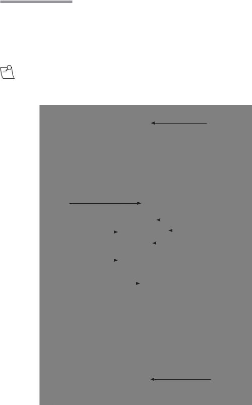
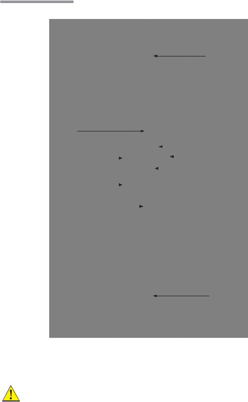
Stellaris® Vision Enhancement System Console
IV Pole
User Interface Screen 
System Switch “ON/OFF”
|
|
|
|
|
|
|
|
|
|
|
|
|
Pneumatic Anterior |
|
|
|
|
|
|
|
|
|
|
|
|
|
|
|
|
|
|
|
|
|
|
|
|
|
|
|
Vit Acuator |
|
|
|
|
|
|
|
|
|
|
|
|
||
Handpiece Connectors |
|
|
|
|
|
|
|
|
|
|
|
|
Expansion Space |
|
|
|
|
|
|
|
|
|
|
|
|
||
|
|
|
|
|
|
|
|
|
|
Fluidic Module |
|||
Surgical Tray |
|
|
|
|
|
|
|
|
|
||||
|
|
|
|
|
|
|
|
|
|||||
|
|
|
|
|
|
|
|
|
|
|
|
||
|
|
|
|
|
|
|
|
|
|
|
|
||
Drawer |
|
|
|
|
|
|
|
|
|
|
|
||
|
|
|
|
|
|
|
|
|
|
|
|
||
|
|
|
|
|
|||||||||
One-Touch Wheel Locking
This is the main unit (see page 4-2), which contains the connections for all handpieces, tray, drawer, Ethernet connector and system housing. On the rear of the main unit, near the IV Pole, are three buttons that move the IV Pole up, down or back to the preset height for the current mode of operation. The console also contains the power supply.
CAUTION: To prevent loss of data, save data before system shuts down.
1-14 Operator's Manual |
110017243EN Rev. H |
1 Getting Started
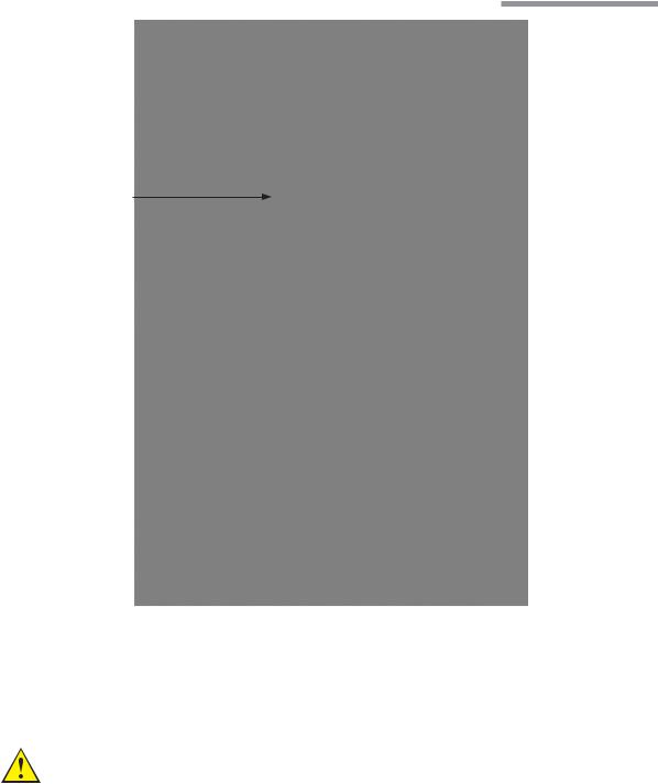
USB Port Access
Air Pressure |
|
Output Connector |
IV Pole Control Buttons |
|
Cord Wrap Hooks
Foot Control Hook
Ultrasound Module
This module contains five ports for connecting system accessories. The top three ports are active and the bottom two are reserved for future use.
Ultrasound Function (Phacoemulsification)
WARNING: Manufacturers of implantable defibrillators recommend that these devices be temporarily disabled when using phacoemulsification or systems on patients with these implants. This is especially important when using pulsed phaco modes of operation. Although the implanted devices are designed to reject electromagnetic interference, and Bausch + Lomb Vision Enhancement equipment is designed to minimize such interference, a chance interaction
110017243EN Rev. H |
Operator's Manual 1-15 |

1 Getting Started
cannot be ruled out. Patients should be questioned to determine if they have such an implant and, if so, the manufacturer should be consulted to determine the proper course of action.
The second port is for ultrasound handpieces. These support phacoemulsification procedures in continuous, pulsed, and burst modes.
Coagulation
The third port is for a coagulation handpiece which provides coagulation power in either Fixed or Linear modes. See page 4-27 for details of use and page 9-12 for technical specifications.
Foot Control
The Foot Control contains the Footpedal and four programmable buttons, and provides the main interface between the user and the Vision Enhancement System for controlling most functions. The Foot Control can be used in a wired or wireless mode. Specifications are in Chapter 9. See page 2-18 for detailed instructions for its use.
Fluidics Function
Each Stellaris® Vision Enhancement System has one fluidics module, either an Advanced Flow or Advanced Vacuum system. Each fluidics module contains a port for a standard pneumatic vitrectomy cutter.
Advanced Flow Function
This function uses a peristaltic-based pump to provide flow from 1 ml/min to 60 ml/min, and vacuum levels from 0 to 650 mmHg. The corresponding pack has both irrigation and aspiration tubing and a 500 ml fluid collection bag which fits in a drawer on the front of the Stellaris® Vision Enhancement System. Irrigation on/ off control is provided by an internal pinch valve. Pneumatic vitrectomy supports both a Linear Cut Rate and a Fixed Cut Rate from 30 to 800 cpm. See page 4-12 for details and Chapter 9 for technical specifications.
Advanced Vacuum Function
This function uses a vacuum-based pump to control the output vacuum range from 0 to 600 mmHg, and uses a rigid 300 ml collection cassette with irrigation and aspiration tubing. Pneumatic vitrectomy supports both a Linear Cut Rate and a Fixed Cut Rate from 30 to 800 cpm. See page 4-7 for details and Chapter 9 for technical specifications.
1-16 Operator's Manual |
110017243EN Rev. H |

1 Getting Started
Air Compressor
The compressor module provides vacuum for aspiration in Advanced Vacuum systems, air pressure for pressurized infusion and air pressure to drive various pinch valves. See Chapter 9 for technical specifications.
Remote Control
The remote control allows control of various surgical functions from a distance. The receiver for the IR
signal is at the bottom of the computer screen. See page 4-6 for details of operation and Chapter 9 for technical specifications.
TruLink® Remote Access (optional)
The TruLink Customer Support Network feature improves system reliability by supporting remote diagnostics and performance analysis. System performance data, but no patient data, is collected by the Stellaris® Vision Enhancement System throughout the surgical day. Upon system shut down, that information can be sent to Bausch + Lomb secure servers through an encrypted, point to point connection. This allows Bausch + Lomb to analyze system performance, help you remotely (where this service is available), and proactively service the system. Surgeon preference files can also be transmitted, to provide a secure off-site backup.
The Ethernet cable that is used to transfer the data can be permanently connected to the Stellaris® Vision Enhancement System, or it can be connected at the end of each surgical day just before shutting down, and then disconnected to move or store the Stellaris® Vision Enhancement System. Upon shutdown, from the “End of Surgery” screen, the system will prompt you if you would like to “Send data to TruLink”, if in agreement, please make sure that the Ethernet cable is connected to the designated port of location and follow instructions. After updating, the system will shut down automatically.
110017243EN Rev. H |
Operator's Manual 1-17 |

1 Getting Started
Multimedia Center (MMC) (optional)
The MMC is an optional accessory that provides streaming video on the surgical screen and microscope overlay capability. The MMC supports NTSC and PAL format composite video and S-video, or a FireWire digital camera.
Main Switch
Connectors from Stellaris
Connectors from TruLink
Connector Status
Connectors from Microscope Camera
Data is transferred between the MMC and the Stellaris® Vision Enhancement System through an Ethernet cable that runs from the back of the MMC system to the Ethernet port on the bottom of the Stellaris® Vision Enhancement System. Whenever the MMC is on and connected and the Stellaris® Vision Enhancement System is in surgical mode, the current video image will appear on screen in the center of the Clock Menu. You can touch the video image itself to toggle between small and large display sizes. You can also touch the outer
edge of the video display to toggle between the video display itself and an animation showing the effect of the handpiece in the eye for the currently selected phase.
If the system has the optional MMC, the TruLink® Remote Access can be activated by connecting the Ethernet port on the MMC to a designated Internet-enabled network connection and enabling the Trulink data download upon shutdown or Remote Access (if available in your area) function on the Stellaris® Vision Enhancement System.
Note: Off-the-shelf Ethernet cable may be used with the Stellaris® Vision Enhancement System to establish or restore connections.
Note: The MMC is not intended for diagnostic purposes.
Before installing the Multimedia Center, please take note of the following:
•Multimedia Center must be installed outside of the sterile field.
•Do not place Balanced Salt Solution bottle or other containers of fluid on top of the Multimedia Center.
•AC power source for the Multimedia Center must have a Ground Fault Interrupt.
1-18 Operator's Manual |
110017243EN Rev. H |

2 User Interface
User Interface
This chapter introduces you to the operating controls, displays and terminology used in the Stellaris® Vision Enhancement System.
2.1. Basic Interface Controls
Spin Button
Pressing one of the arrows will increase (up) or decrease (down) a value to set a system parameter. The current setting is displayed inside the spin buttons. Pressing the displayed number will take you to the numeric keypad (see page 2-3) so you can enter an exact number only if the surgical function is not currently in use.
Push Bar
This is a single button control which displays a command, and initiates that action when you select it. No value is associated with this control and holding it down performs no additional function.
110017243EN Rev. H |
Operator's Manual 2-1 |

2 User Interface
Option List
The Option List allows you to select an option. A small + next to a setting indicates that additional choices are available, and selecting the currently displayed option will bring up a list. Only one option can be selected at a given time. Selecting one option automatically deselects others.
Test Tube Display and Control
This type of control allows you to set the limits of a system parameter. The actual value is displayed above the tube, and the allowable minimum and maximum values are shown beside the tube. The current setting may be changed by selecting and dragging the slider ring. The slider ring may not be positioned below the current setting minimum value. The minimum value may be changed with the surgical function More Screen.
Actual Value
Maximum Limit
Current Max Settings |
|
|
|
Slider Ring |
|
|
|
Function Minimum 
2-2 Operator's Manual |
110017243EN Rev. H |
 Loading...