

Page 1
V-Controller
(BUS 6 VC)
Specification:
Digital Control BUC
Manual
E
5.03047.01
Page 2

Title Manual
Product V-Controller (BUS 6 VC)
Version 5.03047.01
Copyright These operating instructions may be copied by the owner
in any quantity but only for internal use. For other purposes
these operating instructions and extracts thereof must not
be copied or reproduced.
Use and disclosure of information contained in these operating instructions are not permitted.
Designations and company marks contained in these operating instructions may be brand names, the use of which
by third parties for their own purposes may violate the
rights of the holders.
Obligatory These operating instructions are part of the equipment/ma-
chine. These operating instructions must be available to
the operator at all times and must be in a legible condition.
If the equipment/machine is sold or moved to a different lo
cation these operating instructions must be passed on by
the owner together with the equipmen t/ ma ch in e.
After any sale of the equipment/machine this original and
all copies must be handed over to the buyer. After disposal
or any other end of use this original and all copies must be
destroyed.
-
When the present operating instructions are handed over,
corresponding sets of operating instructions of a previous
version are automatically invalidated. Please notice that
specifications/data/information are current values ac
cording to the printing date. These statements are not
legally binding according to the measurement, computa
tion and calculations.
Baumüller Nürnberg Electronic GmbH & Co. KG reserves
the right, in developing its products further, to change the
technical specifications and the handling of the products
concerned without prior notice.
No liability can be accepted concerning the correctness of
the operating instructions unless otherwise specified in the
General Conditions of Sale and Delivery.
Manufacturer Baumüller Nürnberg Electronic GmbH & Co. KG
Ostendstr. 80 - 90
D-90482 Nürnberg
Germany
Tel. +49 9 11 54 32 - 0 Fax: +49 9 11 54 32 - 1 30
www.baumueller.de
-
-
Page 3

Hiermit zeigen wir an, dass die Baumüller Nürnberg Electronic GmbH & Co. KG im Wege der Verschmelzung
mit Wirkung zum 01.12.2004 in der Baumüller Nürnberg GmbH aufgegan gen ist. Ihr zukünftiger Ansprechpart
ner ist damit die
Baumüller Nürnberg GmbH, Ostendstrasse 80-90, 90482 Nürnberg.
Please notify that with effect from 01-12-2004 Baumüller Nürnberg Electronic GmbH & Co. KG merged with
Baumüller Nürnberg GmbH. Your future business partner will be
Baumüller Nürnberg GmbH, Ostendstrasse 80-90, 90482 Nürnberg.
Par la présente, nous vous signalons qu’en voie de la fusion, la Baumüller Nürnberg Electronic GmbH & Co.
KG a été intégrée à la Baumüller Nürnberg GmbH avec effet au 1 décembr e 2004. Votre interlocuteur sera par
conséquent la
Baumüller Nürnberg GmbH, Ostendstrasse 80 – 90, 90482 Nürnberg.
-
Dokument-Nr./Document No.: 5.04058.01 Baumüller Nürnberg GmbH
Page 4

Dokument-Nr./Document No.: 5.04058.01 Baumüller Nürnberg GmbH
Page 5

Table of contents
TABLE OF CONTENTS
1 Safety Information .............................................................................................. 7
2 Technical Data .................................................................................................... 9
2.1 General ................................. .................................................... .............................................. 9
2.2 Electrical Data ...................................................................................................................... 10
2.3 Type Code ................................... ... ... ... ... .... ... ... ... ....................................... ... .... ... ... ...... .... .. 11
3 Transportation, Unpacking .............................................................................. 13
4 Assembly ........................................................................................................... 15
4.1 Dimensions .................................. .......................................................... ............................... 15
4.2 Assembly Note ..................................................................................................................... 16
5 Installation ......................................................................................................... 17
5.1 Danger Information .................. .... ... ... ... ... .... ... ... ... .... ... ... ... .......................................... ......... 17
5.2 Checks Prior to Installation ...................... ............................................................................. 18
5.3 Display .................................. ....................................................... ......................................... 19
5.3.1 Seven-segment Display ............................................................................................................... 19
5.3.2 LED Display Element ........................................................................................................... ........ 20
5.4 Terminal Diagram V-Controller (version: digital controlled BUC) .......................... ... ... ... .... .. 21
5.5 Connection of the Function Inputs ........................................................................................ 22
5.6 Connector Pin Assignment ................................................................................................... 23
5.7 Connection Cables ............................................................................................................... 25
5.7.1 Serial Connection Cable for PC ................................................................................................... 25
5.8 Accessories .......................................................................................................................... 26
6 Commissioning ................................................................................................. 27
6.1 Danger Information .................. .... ... ... ... ... .... ... ... ... .... ... ... ... .......................................... ......... 27
6.2 Initial Commissioning of V-Controller ................................................ .... ... ............................ 30
7 Parameters ........................................................................................................ 31
7.1 Function Diagrams ............................................................................................................... 31
7.2 Power Unit ............................................................................................................................ 33
7.3 Overload Monitoring of Power Unit ........................................... ...................................... .... .. 37
7.4 Pulse Width Modulation ........................................................................................................ 40
7.5 Current Controller ................................. ... .... ... ... ... .... ... ... ... .... ... ... ......................................... 42
7.6 Uzk Controller (Uzk value setting) ........................................................................................ 45
7.7 Drive Manager (Enable the Controller) ................................................................................. 47
7.8 New BUC Parameter ................................... ... ... ... .... ... ... ... .... ... ... ... ...................................... 55
V-Controller (BUS 6 VC) 3
Baumüller Nürnberg Electronic GmbH & Co. KG 5.03047.01
Page 6

Table of Contents
7.9 Data Set Management .......................................................................................................... 59
7.10 Operation System ................................................................................................................. 65
7.11 Ramp Function Generator ........................................ ... ... ... .... ... ... ... ... .... ... ... ... .... ... ... ... ... .... .. 67
7.12 Set Value Generator ............................................................................................................. 71
7.13 Analog Inputs ........................................................................................................................ 73
7.14 Analog Outputs ..................................................................................................................... 78
7.15 Digital Inputs ........................................................................................................................ 80
7.16 Digital Outputs ..................................................................................................................... 84
7.17 Service Interface ............. ... .......................................... ... ... ............................................. .... .. 86
8 Maintenance ...................................................................................................... 91
8.1 Maintenance Information ...................................................................................................... 91
8.2 Error Messages ........................................... ... ...................................................................... 92
8.3 Disposal ................................... .......................................................... ................................... 96
9 Appendix ........................................................................................................... 97
9.1 Declaration by Manufacturer ................ ... .... ... ... ... .... .......................................... ... ... ... ... .... .. 97
9.2 General Conditions of Sale and Delivery .............................................................................. 98
9.3 Parameter List .................................................................................................................... 101
9.4 Index .................................. .................................................... ............................................. 105
4 V-Controller (BUS 6 VC)
5.03047.01 Baumüller Nürnberg Electronic GmbH & Co. KG
Page 7

ABBREVIATIONS
Abbreviations
AC Alternating current
ADR Address byte
AI Function module analog inputs
AM Asynchronous motor
AO Function module analog outputs
BAPS Baumüller parallel interface
BASS Baumüller serial interface
BCC Block check character
BOF Begin of file
BSA Reference potential analog
BSD Reference potential digital
BUM Type of Baumüller converter
BUC Type of Baumüller converter
CE Controller enabling
CPU Central Processing Unit
CT Functio n module coordinate transformation
DA Digital/analog
DC Direct current
DI Function module digital inputs
DSM Function module data set management
EOF End of file
Ext Function module current monitoring
MC Main conductor
MCO Main conductor on
MOE Enable main conductor
I Function module current control
I2t Function module overload monitoring
Inc Unit of position counter
IND Index
Ink No. of graduation marks
J/RI Job / reply identification
LED Light-emitting diode
LGE Telegram length
LT Function module power unit
M Function module drive manager
MM Function module motor model
Mot Function mo dule field angle calculation
MT Function module motor temperature
N Function module speed controller
OS Functio n module operation system
P Parameter number
P Function module position controller
Para. Paragraph
PD Process data
PD Parameter description
PI Parameter identification
PIV Parameter identification value
PN Parameter no.
PS Function module power supply
PV Parameter value
PWM Function module pulse width modulation
RFG Function module ramp function generator
SM Synchronous motor
SPM Space vector modulation
STX Start of text
SV Function module service interface
SVG Function module set value generator
TM Temperature motor
USS®Trademark Siemens,
universal serial interface
ZK Intermediate circuit
V-Controller (BUS 6 VC) 5
Baumüller Nürnberg Electronic GmbH & Co. KG 5.03047.01
Page 8

6 V-Controller (BUS 6 VC)
5.03047.01 Baumüller Nürnberg Electronic GmbH & Co. KG
Page 9
Safety Information
1 SAFETY INFORMATION
General Information
These operating instructions contain all the information necessary for correct operation of the products
described. The document is intended for specially trained, technically qualified personnel who are wellversed in all warnings and commissioning activities. The equipment is manufactured using stat e-o f-theart technology and is safe in operation. It can safely be installed and commissioned and function s without problems if the safety information in these operating instructions is followed.
WARNING
When operating electrical equipment, some parts of the equip ment always ca rr y dange ro us voltag es.
Ignoring these safety instructions and warnings may result in serious personal injury and/or damage
to property.
Only qualified personnel who are familiar with the safety information, assembly, operation and mainte-
nance instructions may carry out work on this equipment.
Danger Information
On the one hand, the information below is for your own personal safety and on the other to prevent
damage to the described products or to other connected equipment.
In the context of the operating instructions and the information on the products themselves, the terms
used have the following meanings:
DANGER
This means that death, severe personal injury, or damage to property will occur unless appropriate
safety measures are taken.
WARNING
This means that death, severe personal injury, or damage to property may occur unless appropriate
safety measures are taken.
V-Controller (BUS 6 VC) 7
Baumüller Nürnberg Electronic GmbH & Co. KG 5.03047.01
Page 10

Safety Information
NOTE
This draws your attention to important information about the product, handling of the product or to a
particular section of the documentation.
Qualified Personnel
In the context of the safety-specific information in this document or on the products themselves, qualified personnel are considered to be persons who are familiar with setting up, assembling, commissioning and operating the product and who have qualifications appropriate to their activities:
Trained or instructed or authorized to commission, ground and mark circuits and equipment in accordance with recognized safety standards.
Trained or instructed in accordance with recognized safety standards in the care and use of appropriate safety equipment.
Appropriate Use
WARNING
You may only use the equipment/system for the purposes specified in the operating instructions and
in conjunction with the third-party equipment and components recommended or authorized by BAU
MÜLLER NÜRNBERG GmbH.
For safety reasons, you must not change or add components on/to the equipment/system.
The machine minder must report immediately any changes that occur which adversely affect the safety
of the equipment/system.
-
8 V-Controller (BUS 6 VC)
5.03047.01 Baumüller Nürnberg Electronic GmbH & Co. KG
Page 11

Technical Data
2 TECHNICAL DATA
2.1 General
This variant of the V-Controller is des igned for the fully digi tal control of the Baum üller feed/feed back
units BUC63 and BUC64. With this V-controller the intermediate circuit direct voltage Uzk is held on a
constant value.
All other known V-Controller variants are designed for speed control of AC motors.
Closed-Loop Control Functions
! Uzk control at 62,5 µs
! Current control at 62,5 µs
– The controller is operated by digital inputs. Via the serial interface RS232 serial port and a PC
the parameterization, commissioning and service as well as archiving control parameter to floppy
disk can be done.
Inputs/outputs
! Digital inputs (24 V):
– Pulse enabling
– 4 programmable function inputs
! Analog inputs:
– 2 analog inputs (0 ... ±10 V), 12 bit resolution
! Serial interfaces:
– RS232 with a transmission rate of 9600 baud, optical separated
! Digital outputs:
–1 relay contact message „ready for use“
–1 programmable function outpu ts
! Analog outputs
–2 analog outputs (0 ... ±10 V), 12 bit resolution
Operation Software
! Up-/Download with PCBASS (see, Technical Description No. 5.96079)
! PCBASS (see, Technical Description No. 5.94004)
V-Controller (BUS 6 VC) 9
Baumüller Nürnberg Electronic GmbH & Co. KG 5.03047.01
Page 12

Technical Data
2.2 Electrical Data
Accuracy of whole system Calculation accuracy 16 bit
Sampling rate of whole system 62,5 µs
2 analog inputs
voltage range
type
input resistance
resolution
5 potential free inputs
low level
high level
input resistance
2 analog outputs
voltage range
maximum output current
resolution
1 relay output
maximum contact load
maximum potential against electronic
ground
3 potential free outputs
joint supply voltage
joint ground
output current per output
Interfaces RS232 service interface
-10 V ... +10 V
differential input
ca. 40 kΩ
12 bit
0 V ... +7.5 V
+13 V ... +30 V
2,5 mA
-10 V ... +10 V
1 mA
12 bit
24 V DC / 1 A
50 V
+ 24 V / 150 mA
ground of 24 V external
50 mA
Power Consumption
+5 V 1,2 A
+8 V 10 mA
+15 V 50 mA
-15 V 50 mA
10 V-Controller (BUS 6 VC)
5.03047.01 Baumüller Nürnberg Electronic GmbH & Co. KG
Page 13
2.3 Type Code
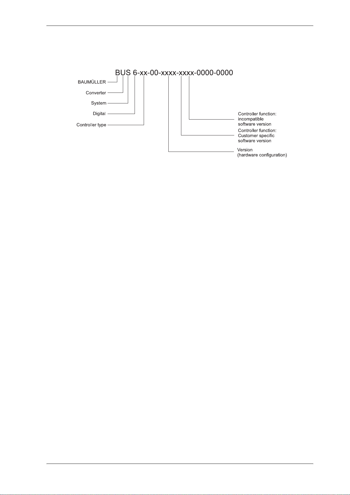
Type of Controller VC Vector controller
Technical Data
Version: 0100
etc.
Closed-Loop Control Function:
Customer-specific software version
Incompatible software version
00
19
V-Controller, digital control of BUC63 and BUC64
No customer-specific software version
software version 19.xx
Example:
BUS6 - VC - 00 - 0100 - 0019 - 0000 - 0000
Controller type: VC Vector controller
00 without meaning
Version: 0100 V-controller; digital closed-loop control for BUC
Closed-loop control function
Customer-spec. software version 00 No customer-specific software version
Incompatible software version 19 Software version 19.xx
0000 without meaning
0000 without meaning
V-Controller (BUS 6 VC) 11
Baumüller Nürnberg Electronic GmbH & Co. KG 5.03047.01
Page 14

Technical Data
12 V-Controller (BUS 6 VC)
5.03047.01 Baumüller Nürnberg Electronic GmbH & Co. KG
Page 15

Transportation, Unpacking
3 TRANSPORTATION, UNPACKING
The units are packed at the factory in accordance with the order.
You should avoid jolting or dropping the package in transit, e.g. when putting the unit down.
You can start assembly after unpacking the equipment and checking that it is complete and undamaged .
The equipment is packed in cardboard, corrugated sheeting and/or wooden packaging that you should
dispose of in accordance with local regulations.
Report any damage that has occurred in transit immediately.
DANGER
If the unit was damaged in transit, a qualified person must check, repair and test it before it may be
connected.
Ignoring this information can result in death, serious personal injury or considerable damage to property.
V-Controller (BUS 6 VC) 13
Baumüller Nürnberg Electronic GmbH & Co. KG 5.03047.01
Page 16

Transportation, Unpacking
14 V-Controller (BUS 6 VC)
5.03047.01 Baumüller Nürnberg Electronic GmbH & Co. KG
Page 17
4 ASSEMBLY
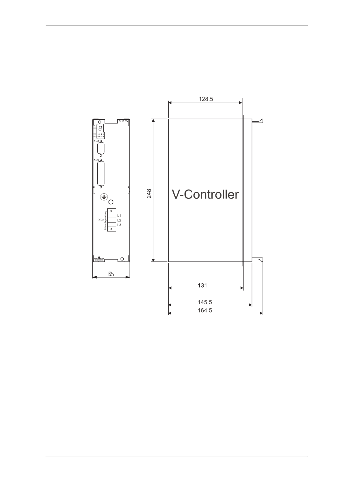
4.1 Dimensions
Assembly
Plug-in depth of cassette
! BUC 63/64: 131,0 mm
The total depth can only be determined in conjunction with the basic unit. In addition, it is necessary to
take into account the dimensions of the connector to be used (approx. 40 mm).
V-Controller (BUS 6 VC) 15
Baumüller Nürnberg Electronic GmbH & Co. KG 5.03047.01
Page 18
Assembly
4.2 Assembly Note
WARNING
You are responsible for mounting the described equipme nt, the mo tor, the tra nsformer an d any ot her
equipment in accordance with appropriate safety regulations (e.g. EN, DIN, VDE); equally you must
ensure that all other relevant national or local regulations are met with regard to cable ratings and pro
tection, grounding, disconnectors, overcurrent protection, etc.
During operation, the unit is protect ed from direct contact such that it is suitable for use in enclosed
electrical premises (DIN VDE 0558 Part 1/07.87, Section 5.4.3.2, provisional sta ndard EN 50178/VDE
0160/ 11.94, Sections 5.2.6, 5.2.7).
-
Plug the controller cassette into the appropriate recess in the basic unit and secure it with the two screws
attached to it.
NOTE
Do not plug in the cassette under voltage!
NOTE
The assembly of the basic unit BUC63 and BUC64 is described in following descriptions:
- "BUC63S/A/F feed/feed back unit with digital control" (document no. 5.03046)
- "BUC64S/A/F feed/feed back unit with digital control" (document no. 5.03054)
16 V-Controller (BUS 6 VC)
5.03047.01 Baumüller Nürnberg Electronic GmbH & Co. KG
Page 19

Installation
5 INSTALLATION
5.1 Danger Information
WARNING
You are responsible for mounting the controller in accordance with appropriate safety regulations (e.g .
DIN, VDE); equally, you must ensure that all other relevant national and local regulations are met with
regard to cable ratings and protection, grounding, disconnectors, overcurrent protection, etc.
The power converter's power cables are energized!
During operation, the principles on which the power converter and the motor work lead to leakag e currents to earth that are dissipated via the specified p rotective earth s and may result in a cu rrent- opera
ted e.l.c.b. on the input side blowing prematurely.
Speed monitoring systems in the equipment must not just be complemented by a stand-alone monitoring system on the motor in the case of speed-critical drives. You can implement this control of the
RPM speed, which is independent of the controller, by means of inductive, optical or torque-dep endent
encoders. Refer to the appropriate mo to r's op e ratin g an d ma in te na nc e ins t ru ct ion s.
Be particularly careful before touching the drive shaft directly or indirectly with your hands. This is only
allowed when the system is deenergized and the drive is stationary.
Safety devices must never be deactivated.
According to applicable regulations (EN 60204 Part 1 and VDE 0113 Part 1), stopping the drive using
the enable inputs of the control electronics does not, on its own, represent a safe stop condition. A
disturbance in the power converter's control electronics can lead to accidental starting of the motor.
-
V-Controller (BUS 6 VC) 17
Baumüller Nürnberg Electronic GmbH & Co. KG 5.03047.01
Page 20
Installation
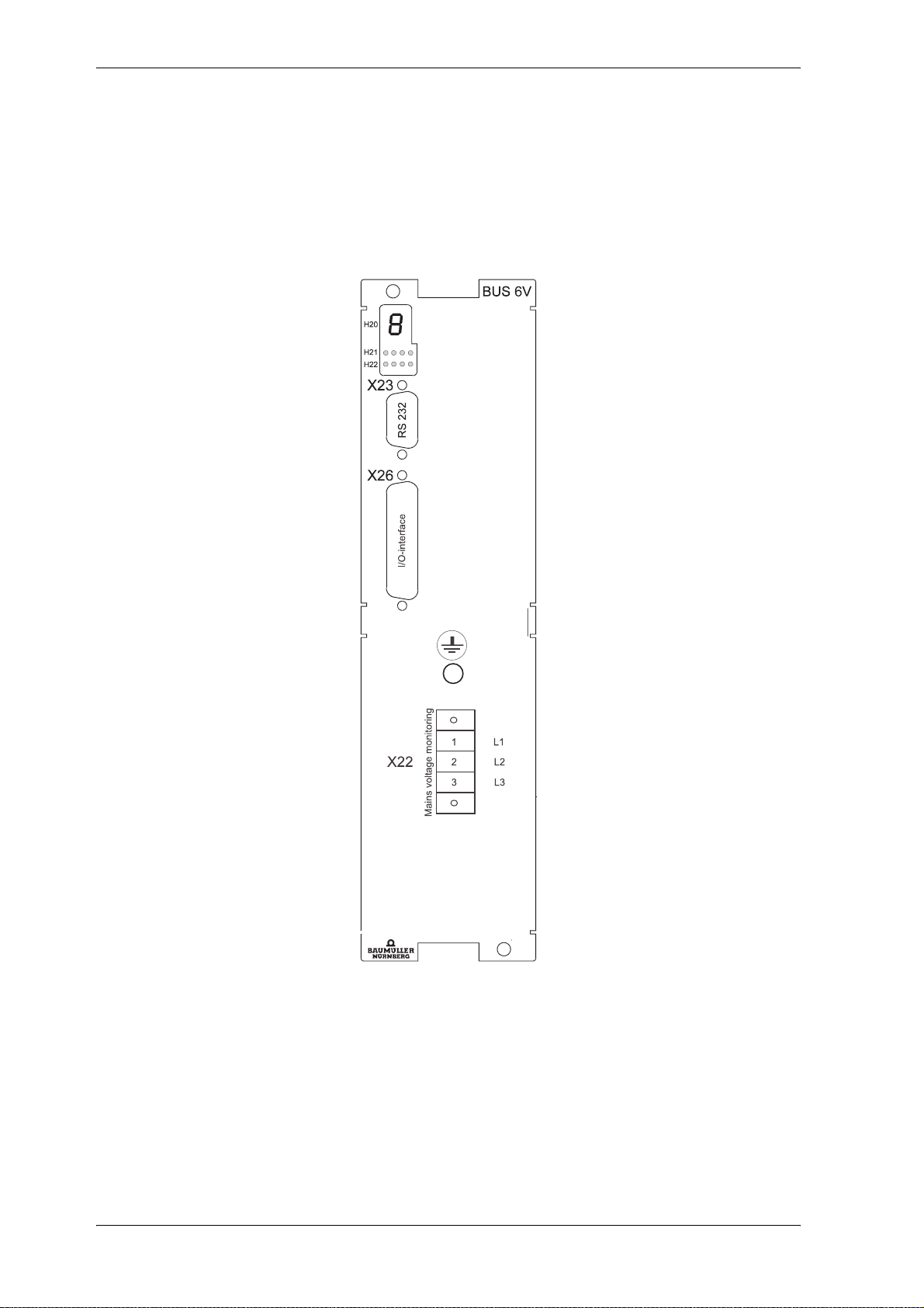
5.2 Checks Prior to Installation
! Note down the type code of the un it an d m oto r
! Check the connections by means of the terminal diagram
! Connection of the plugs :
18 V-Controller (BUS 6 VC)
5.03047.01 Baumüller Nürnberg Electronic GmbH & Co. KG
Page 21
Installation
5.3 Display
5.3.1 Seven-segment Display
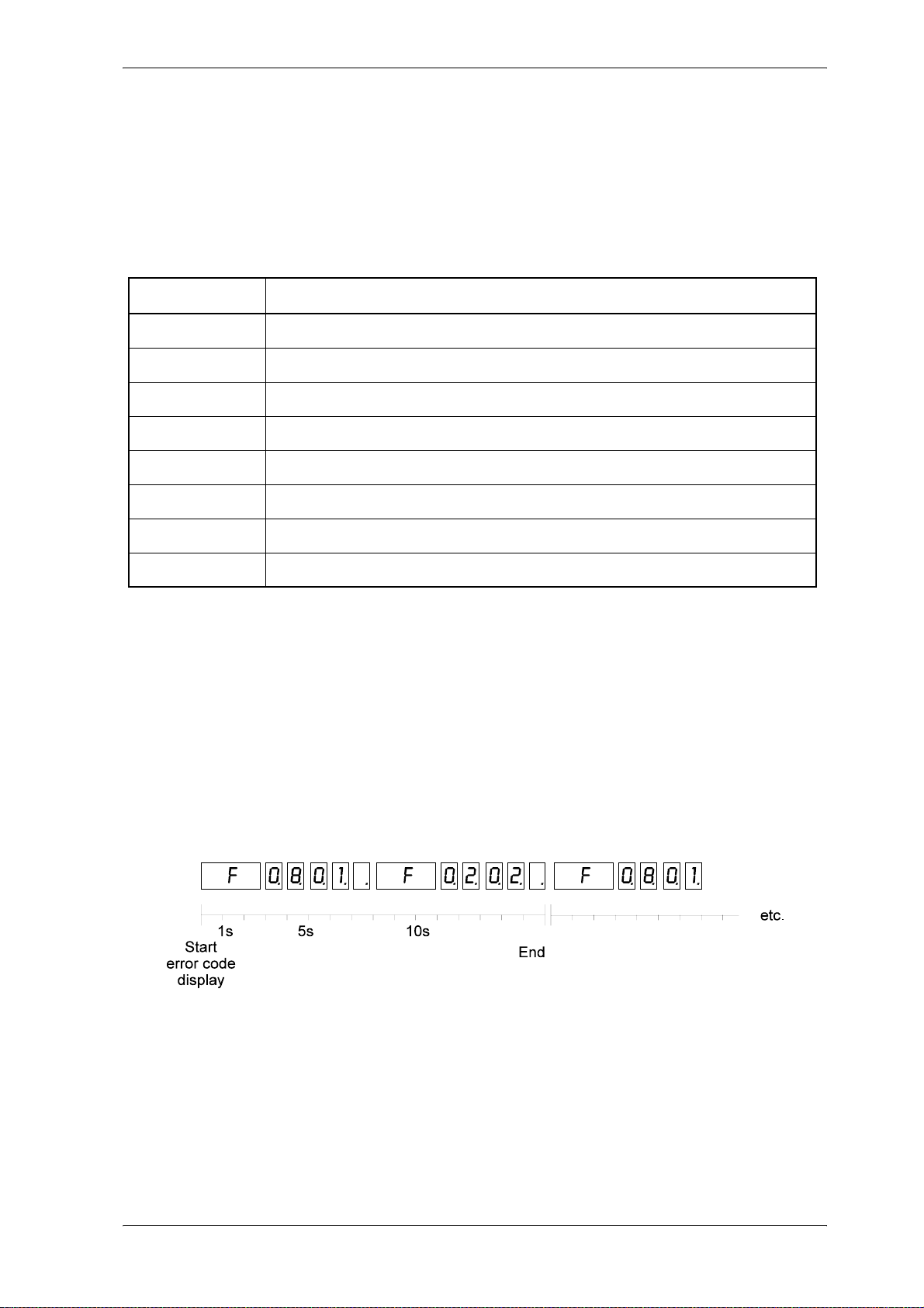
A 7-segment display is attached to the front of the V-Controller, which shows the state in the drive manager's state machine (P120 - P133).
Display Meaning
0 NOT READY TO START
1 INHIBIT START
2 READY TO START
9 SWITCHED ON, waiting for pulse inhibit
3 SWITCHED ON, waiting until the pre-control time (P602) is run-up
4 OPERATION ENABLED, ready-for-use relay is switched on
E FAULT_REACTION_ACTIVE
F FAULT
The following display mode is active only in the status FAULT:
Initially status identifier "F" is shown for three seconds to indicate the fault status. The "F" is followed by
the four digits of the error code. The system outputs them with a decimal point, which clearly differenti
ates this status from the others in the device control. After the last digit, the system deactivates the display – apart from the decimal point – for one second. After this, the entire procedure is repeated.
If several errors are pending, the system, displays the entire list in this way.
If you acknowledge an error that is just being shown in display mode, the system still continues to display
it until the end of this sequence. The next time the error list is processed, this error is no longer visible.
Example in the case of error codes 0801 and 0202:
-
Information on error codes: see Error Messages on page 92.
V-Controller (BUS 6 VC) 19
Baumüller Nürnberg Electronic GmbH & Co. KG 5.03047.01
Page 22
Installation
5.3.2 LED Display Element
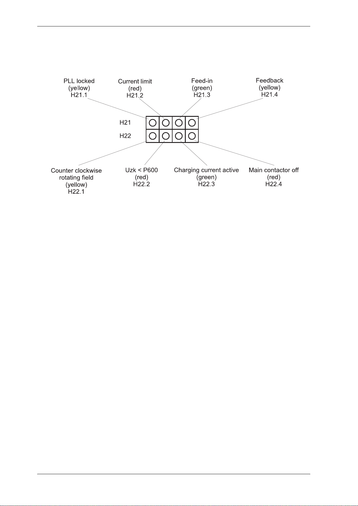
An LED display, which gives additional information, is loca te d be low the 7- segm e nt disp lay.
see function module LED display
20 V-Controller (BUS 6 VC)
5.03047.01 Baumüller Nürnberg Electronic GmbH & Co. KG
Page 23
Installation
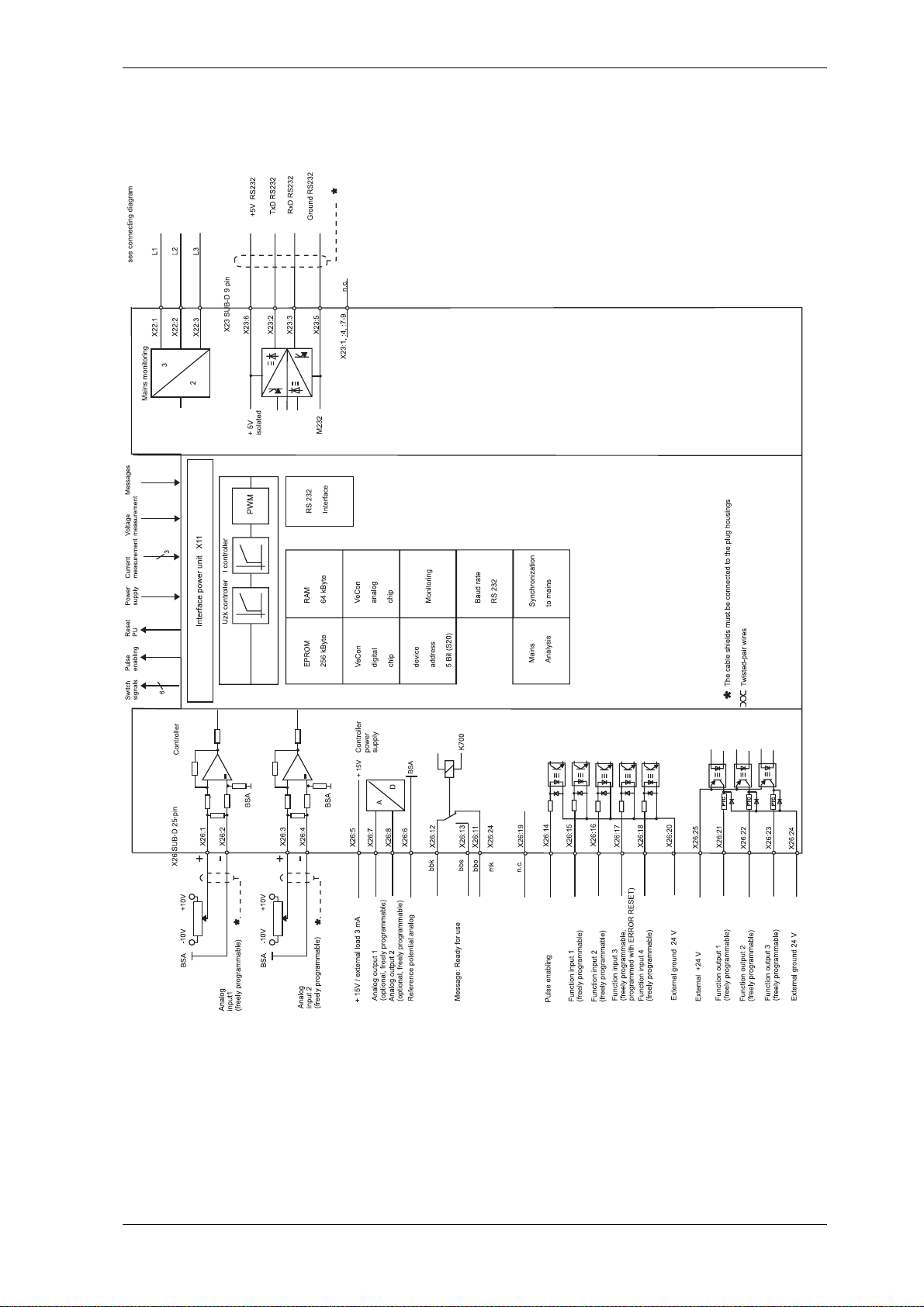
5.4 Terminal Diagram V-Controller (version: digital controlled BUC)
V-Controller (BUS 6 VC) 21
Baumüller Nürnberg Electronic GmbH & Co. KG 5.03047.01
Page 24
Installation
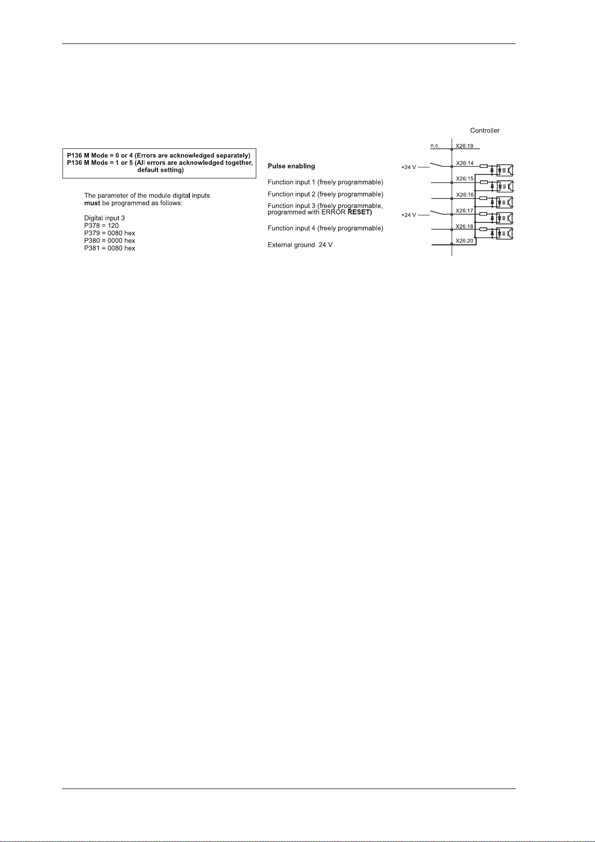
5.5 Connection of the Function Inputs
22 V-Controller (BUS 6 VC)
5.03047.01 Baumüller Nürnberg Electronic GmbH & Co. KG
Page 25
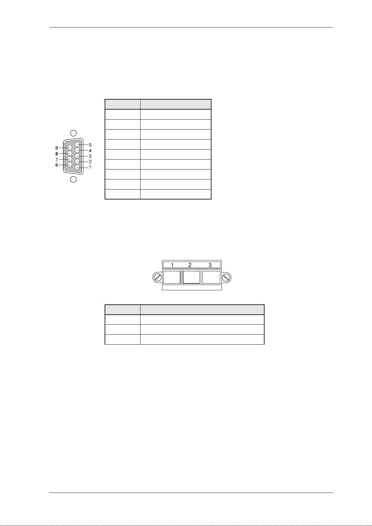
5.6 Connector Pin Assignment
RS232 Interface
X 23 SUB-D socket 9-pin
Installation
Socket
Pin no. Assignment
1 not assigned
2 TxD RS232
3 RxD RS232
4 DTR, DSR
5 ground RS232
6 +5V RS232
7 RTS, CTS
8 RTS, CTS
9 not assigned
Measurement of the mains voltage
X22 plug 3-pin (see accessories)
Pin no. Assignment
1 phase L1 mains voltage
2 phase L2 mains voltage
3 phase L3 mains voltage
V-Controller (BUS 6 VC) 23
Baumüller Nürnberg Electronic GmbH & Co. KG 5.03047.01
Page 26
Installation
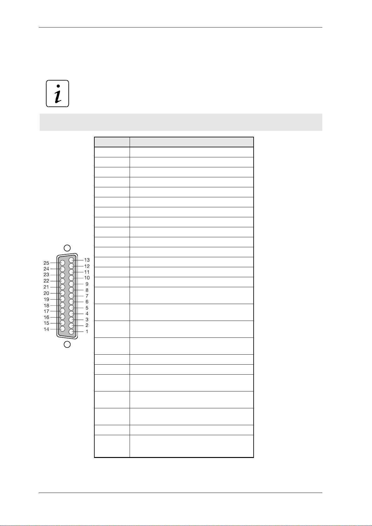
Analog/Digital Interface
X26 SUB-D socket 25 pin
NOTE
A secure separation must be ensured externally.
Pin no. Assignment
1 analog input 1, differential signal +
2 analog input 1, differential signal 3 analog input 2, differential signal +
4 analog input 2, differential signal 5 analog power supply, + 15 V
6 analog power supply, analog reference potential
7 analog output 1
Buchse
8 analog output 2
9 must not be connected !
10 must not be connected !
11 bbo relay break contact ready for use
12 bbk relay changeover contact ready for use
13 bbs relay make contact ready for use
14 pulse enabling (24 V)
15 digital input 1 (24 V)
16 digital input 2 (24 V)
17 digital input 3 (24 V)
(programmed with reset error)
18 digital input 4 (24 V)
19 must not be connected !
20 ground for digital inputs 1 to 4
21 digital output 1 (24 V)
22 digitaler output 2 (24 V)
(ready for pulse enabling)
23 digitaler output 3 (24 V
24 ground digital outputs 1 to 3
25 +24 V for digital inputs 1 to 4,
(freely programmable)
(freely programmable)
(freely programmable)
(freely programmable)
(main contactor on)
pulse enabling and
digital outputs 1 to 3
24 V-Controller (BUS 6 VC)
5.03047.01 Baumüller Nürnberg Electronic GmbH & Co. KG
Page 27
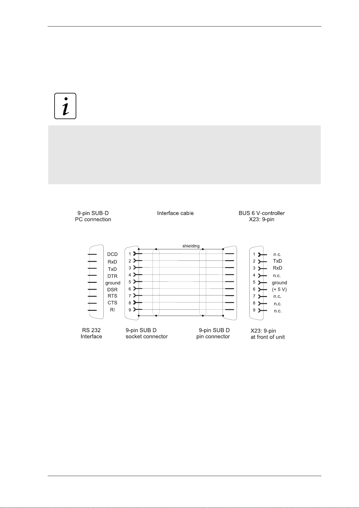
5.7 Connection Cables
5.7.1 Serial Connection Cable for PC
NOTE
Connect PC via isolating transformer.
Description of the operational programmes refer to
- Up-/Download with PCBASS (see operation manual no. 5.96079)
- PCBASS (see operation manual no. 5.94004)
! 9-pin PC connection (interface cable PC, part no. 00213283
Installation
V-Controller (BUS 6 VC) 25
Baumüller Nürnberg Electronic GmbH & Co. KG 5.03047.01
Page 28
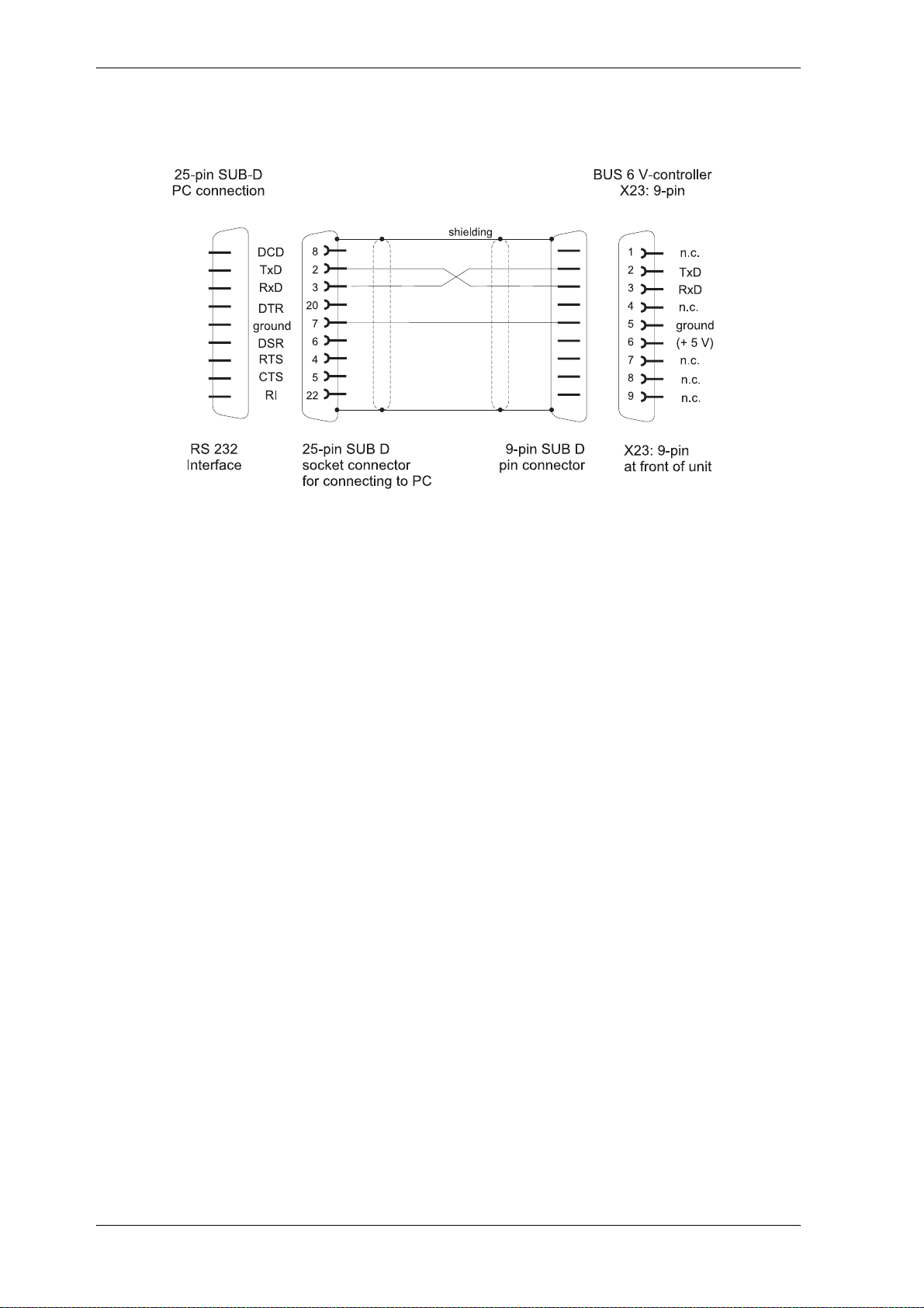
Installation
! 25-pin PC connection (not available)
5.8 Accessories
! Interface cable PC (3 m)
X23 RS232
! Plug part with screw flange
X22 3-pin RM 7,62mm
Part no.
00213283
00362609
26 V-Controller (BUS 6 VC)
5.03047.01 Baumüller Nürnberg Electronic GmbH & Co. KG
Page 29

Commissioning
6 COMMISSIONING
6.1 Danger Information
WARNING
This equipment carries a dangerously high voltage and, depending on the version, may have dangerous rotating parts (fans). Ignoring the safety and warning information may result in death, severe personal injury or damage to property.
You are responsible for mounting the power converter, the motor, the commutating reactor and any
other equipment in accordance with appropriate safety reg ulations (e.g. DI N, VDE); equally, you must
ensure that all other relevant national and local regulations are met with regard to cable ratings and
protection, grounding, disconnecters, overcurrent protection, etc.
The most important factors for protecting people a re the DIN/VDE protective m easures and safety regulations. If there are no protective earth connections on the equipment, commutating reactor or the
motor, personal injuries are inevitabl e, since the surfaces may carry dangerously high voltages.
The power converter's power cables are energized!
The mains unit and the field connector of the power converter carry a dangerous voltage even when
the main contactor has dropped.
During operation, the principles on which the power converter and the motor work lead to leakag e currents to earth that are dissipated via the specified p rotective earth s and may result in a cu rrent- operated e.l.c.b on the input side blowing prematurely.
In the case of a short-circuit to frame or to ground, a direct proportion ma y arise in the leakage current
that makes triggering a higher level current-operated e.l.c.b either more difficult or totally impossible.
Make the PE connection in accordance with DIN EN 60204/VDE 0113 Part 1/06.93; Section 8.2.2 taking into account provisional standard EN 50178/ VDE 0160/11.94, Sections 5.3.2.1 and 8.3.4.4.
Before carrying out commissioning, check whether the plastic covers over the power stage connections are in place.
V-Controller (BUS 6 VC) 27
Baumüller Nürnberg Electronic GmbH & Co. KG 5.03047.01
Page 30

Commissioning
WARNING
Before switching on the drive, you must carefully check the functions of all the higher level safety
equipment to prevent injury to people.
Contact protection in accordance with paragraph 4 Section 4 VBG 4
Protection against direct contact co mp r ises all t he m easures against danger that can result from tou-
ching the active parts of electrical equipment.
You must therefore protect the active parts from being touched by means of insulation, the construc-
tion and arrangement of the equipment or permanently mounted guards. The guards in question are
standard covers, barriers and procedures that guarantee that people cann ot touch active parts that are
carrying power.
Switching cabinets must have an emergency off facility to switch off any voltages that could be dangerous. This does not include equipment which , if switched off, would cause an even more dangero us
situation. The emergency off releasing element must be arranged in such a wa y that it can be reached
quickly in case of danger. In the case of work that is considerably more dangerous than usual, another
person must be present.
The machine minder must ensure that unauthorized people do not work at the machine.
28 V-Controller (BUS 6 VC)
5.03047.01 Baumüller Nürnberg Electronic GmbH & Co. KG
Page 31
Commissioning
WARNING
The machine minder must report immediately any changes tha t occur at the machine which adversely
affect safety.
This list doesn't show the complete enumeration of the measures, which are necessary for the safe
operation of the device. In case you require further information or if specific problems arise, please
contact Baumüller Nürnberg Electronic GmbH & Co. KG or a subsidiary.
Pay attention to the safety instructions in chapter 1 of this operating manual.
NOTE
The operator must electrostatically discharge him self b efore touching the modu les, in order to protect
against electronic modules of high voltage, which arise due to electrostatic charge. This can happen
if a conductive earthed subject is touched shortly before.
Observe electrostatic discharge protection: Before touching the plug, discharge electrostatic energy
from your body by touching a grounded conductive object, for example.
V-Controller (BUS 6 VC) 29
Baumüller Nürnberg Electronic GmbH & Co. KG 5.03047.01
Page 32
Commissioning
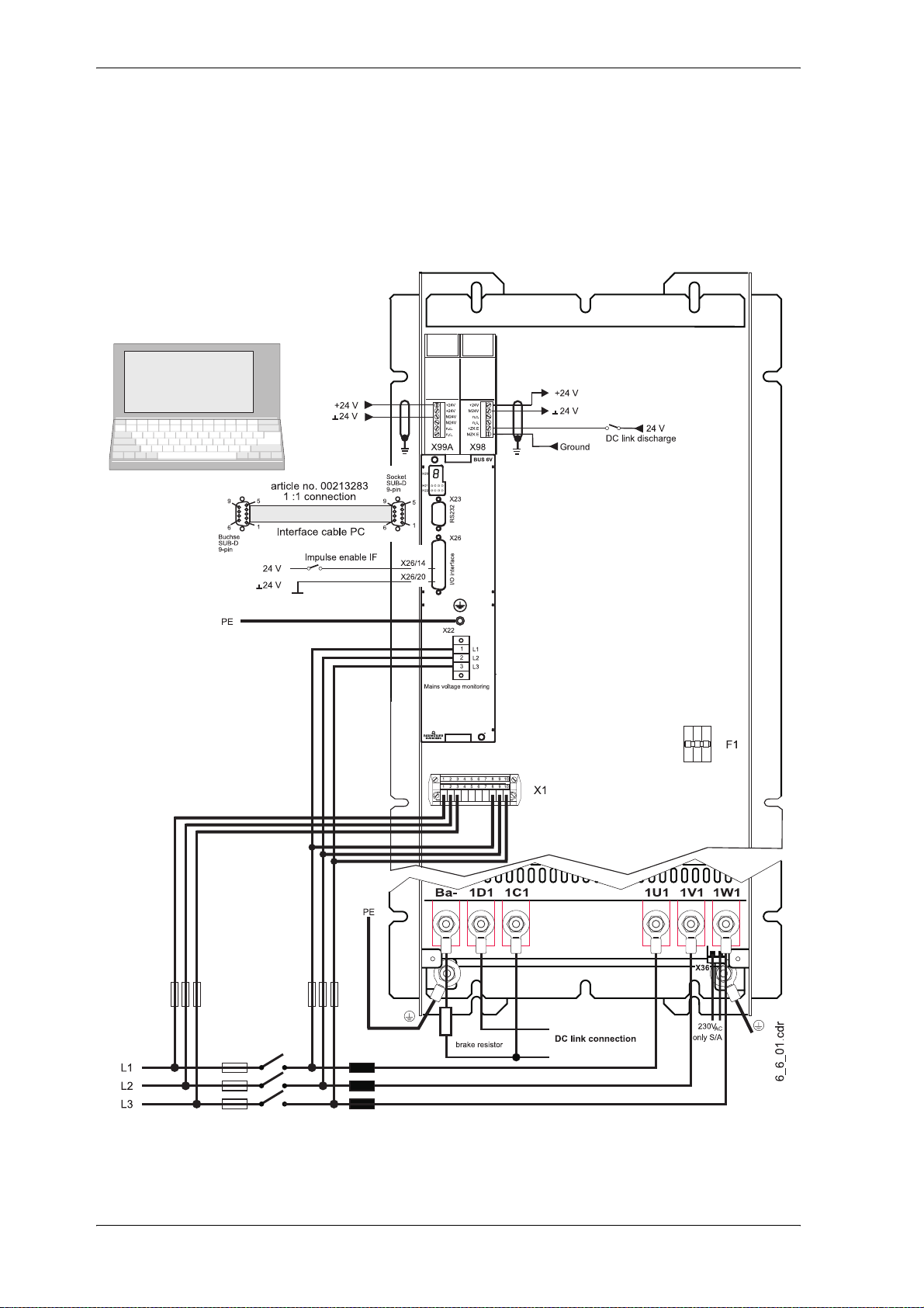
6.2 Initial Commissioning of V-Controller
A certain minimum setup of the drive components is required to commision a drive. The following diagram shows how the components of a drive could be connected. Observe safety no te s which ar e given
in the manuals of every component. Please note for further commissioning the controller type and the
type codes of the other components.
30 V-Controller (BUS 6 VC)
5.03047.01 Baumüller Nürnberg Electronic GmbH & Co. KG
Page 33
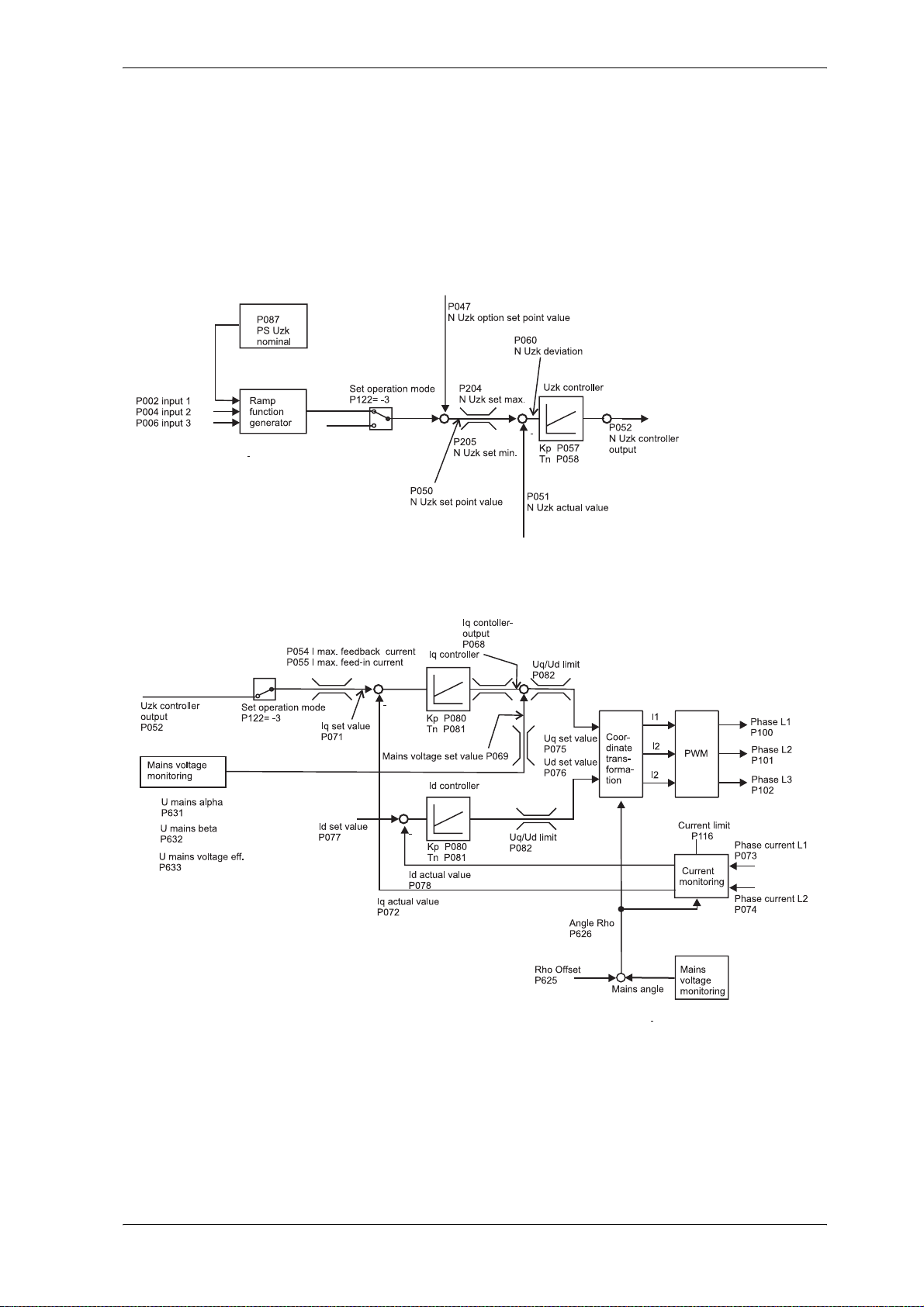
7 PARAMETERS
7.1 Function Diagrams
Overview V-Controller
Parameters
V-Controller (BUS 6 VC) 31
Baumüller Nürnberg Electronic GmbH & Co. KG 5.03047.01
Page 34
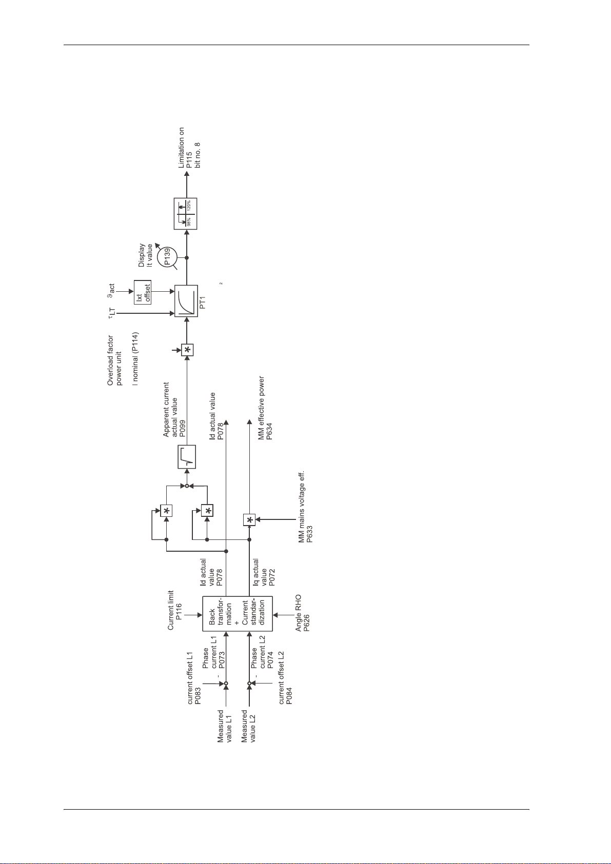
Parameters
Current Measurement and Monitoring
32 V-Controller (BUS 6 VC)
5.03047.01 Baumüller Nürnberg Electronic GmbH & Co. KG
Page 35
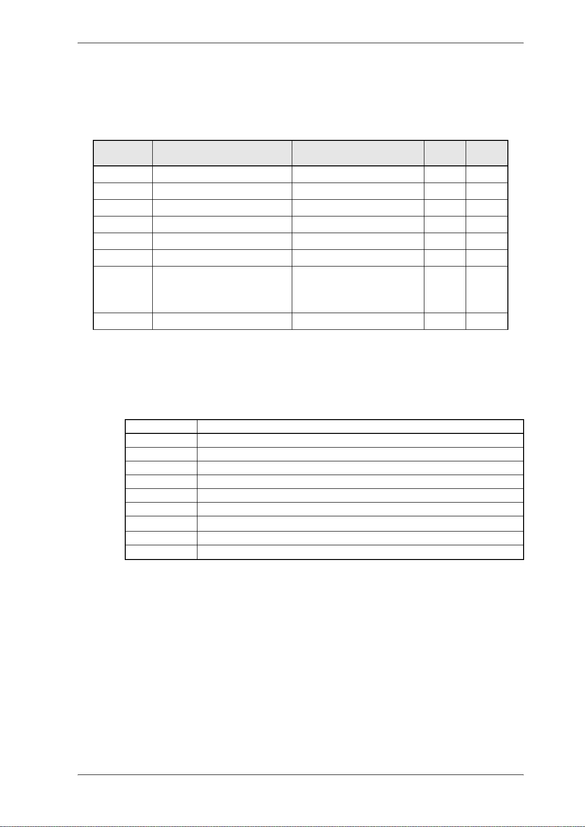
7.2 Power Unit
Parameter overview
Parameter
Parameter Name Range
P115 PU state 0000 ... FFFF
P090 PU mode 0000 ... 0007
P117 PU type 0.1 ... 65535
P114 PU I nomin al 0.1 ... 2500,0 A
P113 PU I max 0.1 ... 2500,0 A
P119 PU overload time 0.00 ... 600,00 s
P116 PU I limit The range depends on the PU.
P118 PU temperature -80 ... 130 °C
Permitted range:
PU Inom
------------------------
4
Parameter description
P115 PU state
This parameter displays the state of the powe r unit .
Bit no. Meaning
0 ... 2 0 : STOP 1 : RUN
3 1 : Error in function module, error code see M error code (P124)
4 1 : Power unit reset is active
5 1 : Pulses are enabled, power unit is active
6 1 : Power unit temperature > 80 °C
7 1 : Power unit ready for use
8 1 : PU monitoring is active, current reduction to 100% I
9 1: Short circuit temperature sensor
10 ... 15 reserved
min. ... max.
≤ PU I limit ≤ PU I max
nom
Unit Display
only
!
!
!
!
!
A
!
power unit
V-Controller (BUS 6 VC) 33
Baumüller Nürnberg Electronic GmbH & Co. KG 5.03047.01
Page 36
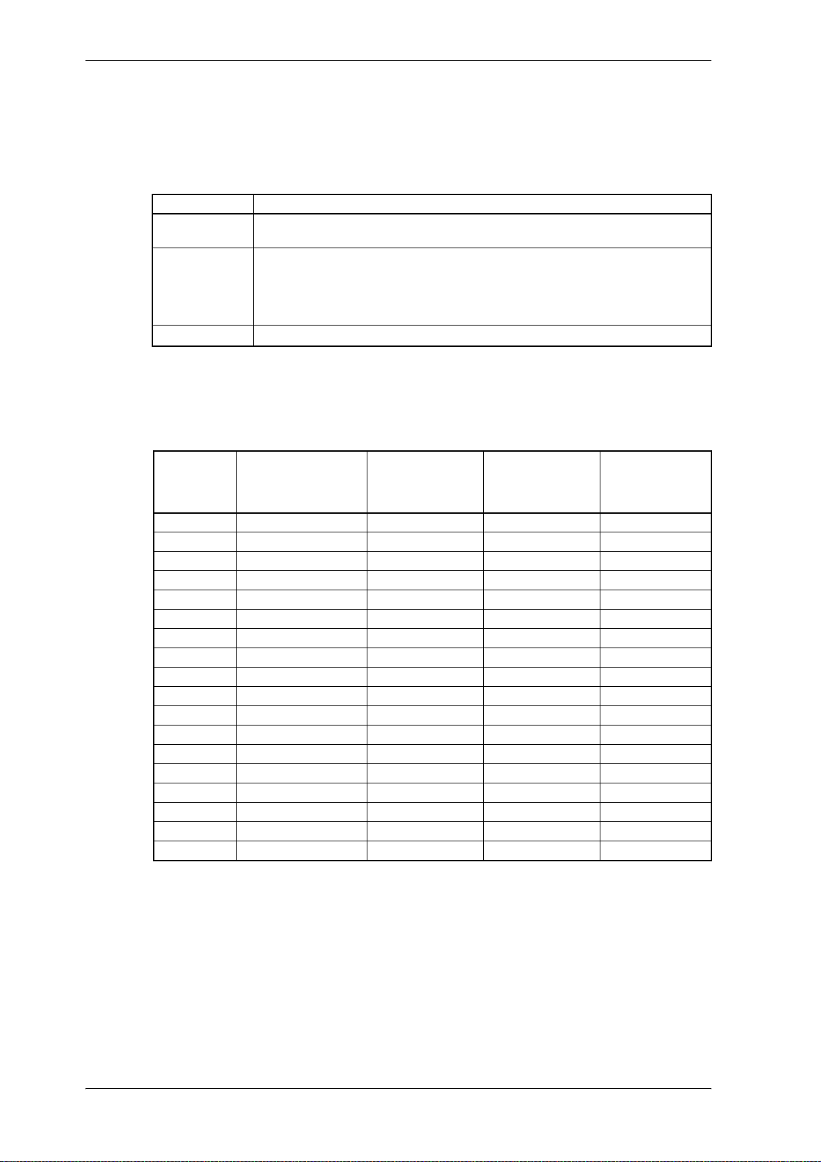
Parameter
P090 PU mode
The parameters P114, P113 and P119 can only be changed, if PU Mode 0001
the password is correct.
Bit no. Meaning
0 0 : Read the power unit´s specifier, data is set according to the specifier
1
2 ... 15 reserved
P117 PU type
The parameter displays the type of the power unit. The value 0 characterizes an unknown
power unit.
is set and
hex
1 : Specifier is not read, PU data is read from EPROM
Short circuit monitoring temperature sensor
0 :If the temperature falls below the threshold value of -40°C the error bit in the
PU status is set and the controller is disabled.
1 :If the temperature falls below the threshold value of -40°C only the warning bit No. 9 in
the PU status is set. The controller is not disabled.
Version Power unit PWM frequency
P103 = 8 kHz
nominal/peak cur-
rent effective
6210 BUS621 5 A / 7,5 A 6,3 A / 7,5 A 1
6211 BUS621 10 A / 15 A 12,5 A / 15 A 1
6212 BUS621 3 A / 3,7 A 3,1 A / 3,7 A 1
622 BUS622 15 A / 22 A 18,3 A / 22 A 1
623 BUS623 20 A / 30 A 25 A / 30 A 1
6240 BUS624 38 A / 57 A 47,5 A / 57 A 1
6241 BUS624 45 A / 67,5 A 56,3 A / 67,5 A 1
600 BUM60 12 A / 24 A 12 A / 24 A 1
601 BUM60 6 A / 12 A 6 A / 12 A 1
602 BUM60 3 A / 6 A 3 A / 6 A 1
612 BUM61 24 A / 45 A 30 A / 45 A 1
613 BUM 61 32 A / 60 A 40 A / 60 A 1
62 BUM62 57,7 A / 75 A 75 A / 97,5 A 120
6203 BUM62T 75 A / 97 A 100 A / 130 A 120
6201 BKH62 75 A / 97,5 A 90 A / 97,5 A 1
63 BUC63 115 A / 150 A 150 A / 195 A 120
6301 BKH63 150 A / 195 A 180 A / 195 A 1
64 BUC64 231 A / 300 A 300 A / 390 A 120
PWM frequency
P103 = 4 kHz
nominal/peak cur-
rent effective
Overload time in s
34 V-Controller (BUS 6 VC)
5.03047.01 Baumüller Nürnberg Electronic GmbH & Co. KG
Page 37
Parameter
How to change the power unit data in case of an unknown power unit, see below:
PU mode = 0001
DSM command = 0 P190
DSM command = 8 P190
Enter password 1
Parameter P013, P114 and P119 can now be se t and th e PU character i zatio n is no t be r ead
at booting.
Values for peak current (P115), nominal current (P114) and overload time (P119) see table
above.
PU I max = set table value P113
PU I nominal = set table value P114
PU overload time = set table value P119
PU I limit = set value P116
DSM command = 0 P190
DSM command = 5 P190
→ Values are stored in the EEPROM
The data of the power unit is available now on every switch on .
hex
P090
After each change of parameter P103 (PWM) the data must be saved, the controller must
be switched off and must be booted new to set the new power unit parameters.
P114 PU I nominal
This parameter displays the power unit´s no minal current. This current can be supplied for an
unlimited time.
P113 PU I max
This parameter shows the power unit´s peak current. The peak current is greater or equal
power unit nominal current.
P119 PU overload time
During the overload time the power unit can supply the peak curr ent. After that the curr en t is
limited to the nominal current (P114). The bit no. 8 in PU state (P115) displays the limitation.
NOTE
V-Controller (BUS 6 VC) 35
Baumüller Nürnberg Electronic GmbH & Co. KG 5.03047.01
Page 38
Parameter
P116 PU I limit
This parameter sets the standardization of the current controlling.
Standardization
The limits of this parameter depend on the power unit used.
The standardization of the current controlling must not be changed if pulses are enabled.
P118 PU temperature
This parameter displays the power unit´s temperature.
A temperature over 80 °C enables the bit no. 6 in PU state (P115). Exceeds the power unit´s
temperature 85 °C the error 0205
100 %
NOTE
↔ I limit
appears.
hex
36 V-Controller (BUS 6 VC)
5.03047.01 Baumüller Nürnberg Electronic GmbH & Co. KG
Page 39
Parameter
7.3 Overload Monitoring of Power Unit
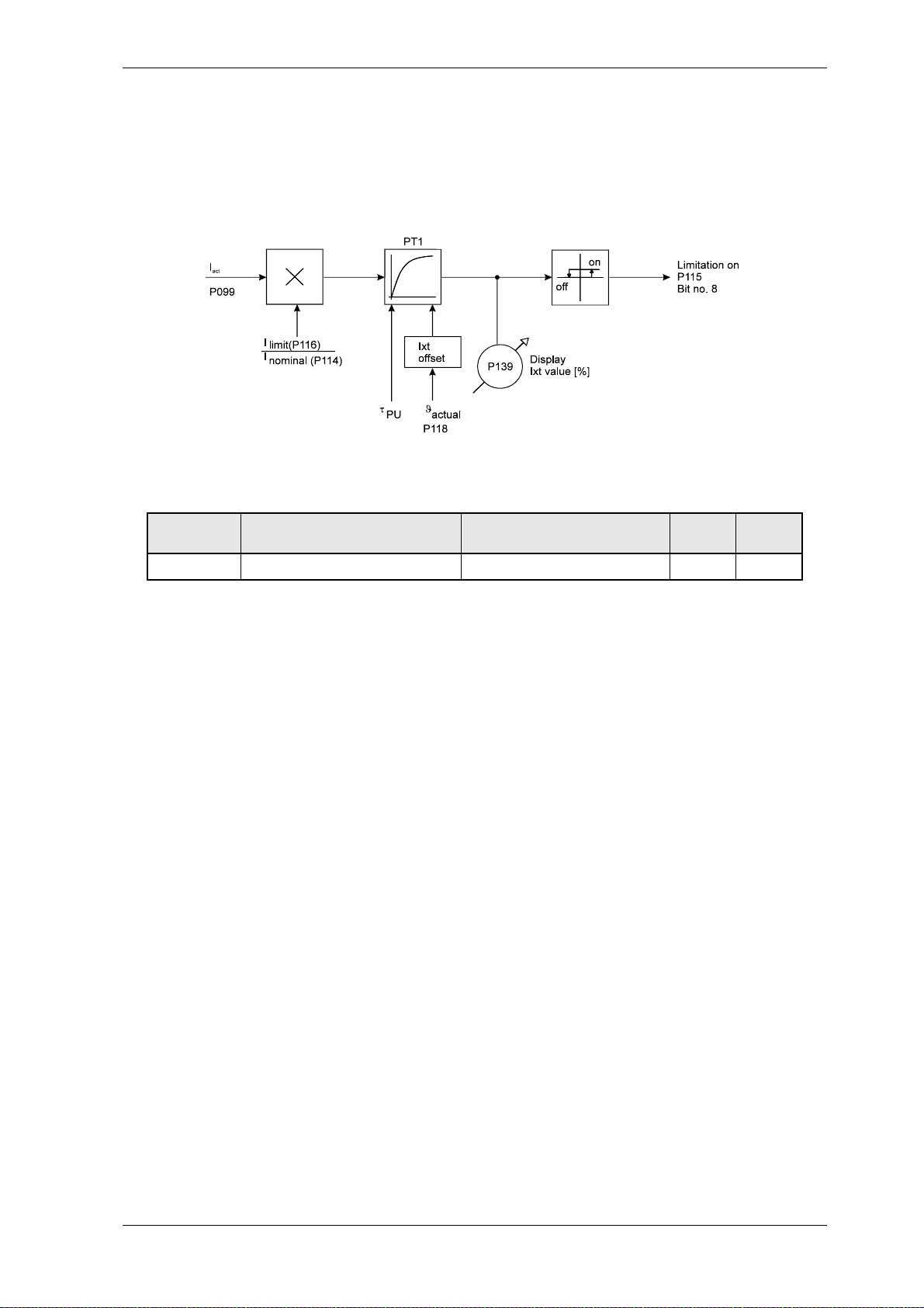
This monitoring protects the power unit from thermic overload. The temperature of the power unit is imitated and monitored by a Ixt model.
Parameter overview
Parameter Name Range
P139 PU Ixt value 0,00 ... 400,00 %
Parameter description
P139 PU Ixt value
This parameter displays the actual Ixt value of the overload monitoring. At a value equal
100 % follows a current limitation to nominal current (P114). Drops the Ixt value below 95%
the current value is set to PU I limit (P116).
Current set value (I
PU nominal current (I
PU maximum current (I
PU limit current (I
PU overload time (tO) [s] P119
PU temperature (ϑact) [°C] P118
PU Ixt value (Ixt) [%] P139
PU overload factor max (u
PU overload factor actual (u) [%]
PU thermic time constant (τPU) [s]
PU reaction time (t
PU Ixt offset (Ixt offset) [%]
) [A
] P099
act
eff
) [A
nom
max
limit
max
rea
]P114
eff
) [A
]P113
eff
) [A
]P116
eff
) [%]
) [s] time till the limitation of I
min. ... max.
Unit Display
only
!
nom
u
u
τ
max
PU
----------
100⋅=
I
nom
I
act
----------
100⋅=
I
nom
t
-------------------------------------- -–=
ln
o
u
--------------------------- -
max
u
100–
max
[%]
[%]
[s]
I
max
V-Controller (BUS 6 VC) 37
Baumüller Nürnberg Electronic GmbH & Co. KG 5.03047.01
Page 40

Parameter
– for power unit temperature > 45 °C
ϑ
act
Ixtoffset
– otherwise
Ixt offset = 0 %
t
offτPU
Example:
I
nom
I
max
= 150 A
= 195 A
(BUC 63)
eff
(BUC 63)
eff
tu = 120 [s] (BUC 63)
I
= 180 A
limit
ϑ
act
= 35 °C
u
max
eff
195
--------- -
100⋅ 130==
150
---------------------------------
85
-------------------------------- -
ln⋅=
u Ixtoffset–
o
C45oC–
u100–
45oC–
[%]
100⋅=
[%]
180
--------- -
u
τ
t
100⋅ 120==
150
120
-------------------------------------– 81 8,==
PU
off
130 100–
--------------------------
ln
130
120 100–
81 8,–
--------------------------
ln⋅ 147==
120 0–
[%]
[s]
[s]
38 V-Controller (BUS 6 VC)
5.03047.01 Baumüller Nürnberg Electronic GmbH & Co. KG
Page 41
Parameter
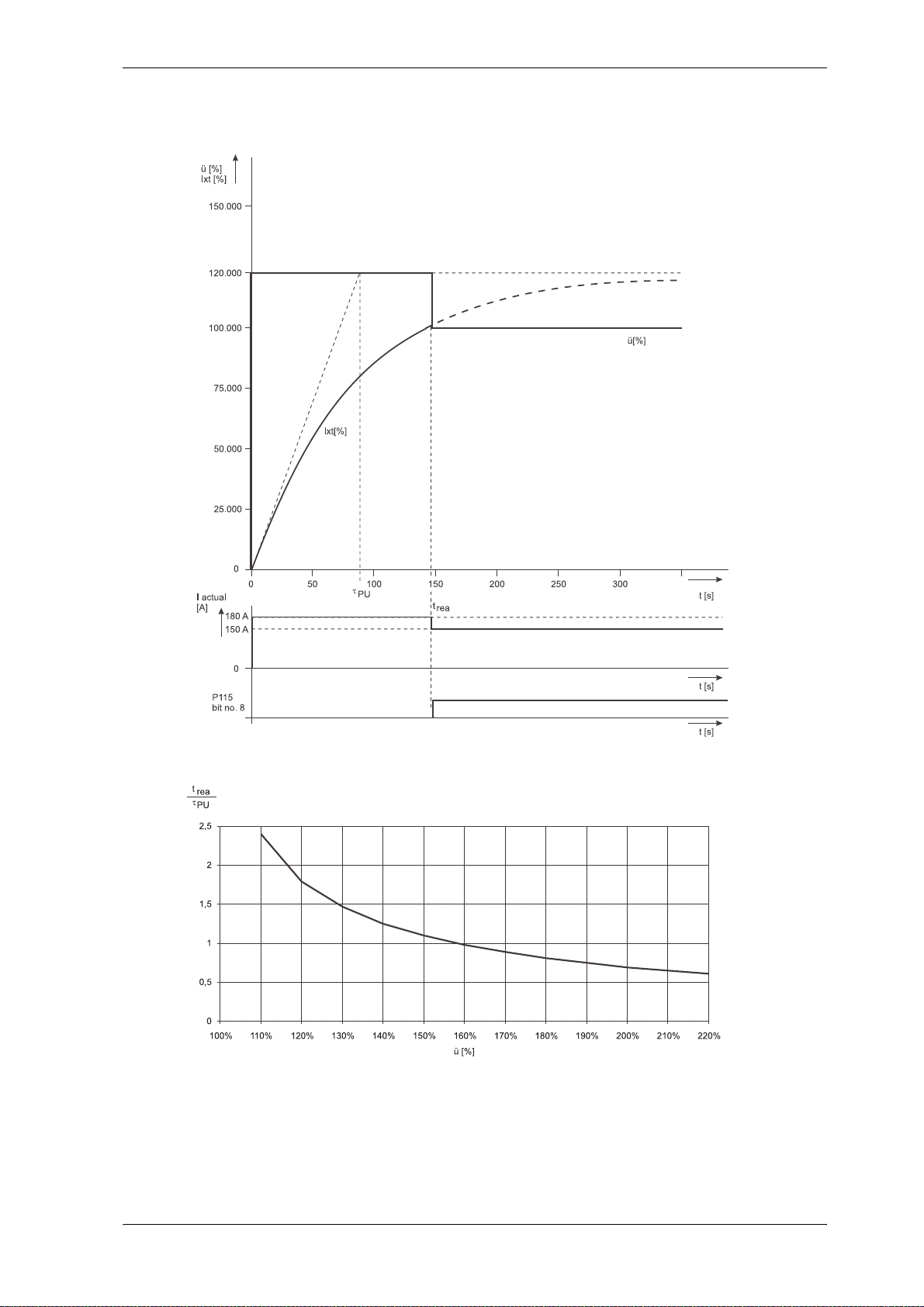
This characteristic curve refers to a „cold“ power unit (Ixt Offset = 0%; ϑ
V-Controller (BUS 6 VC) 39
Baumüller Nürnberg Electronic GmbH & Co. KG 5.03047.01
< 45°C).
act
Page 42
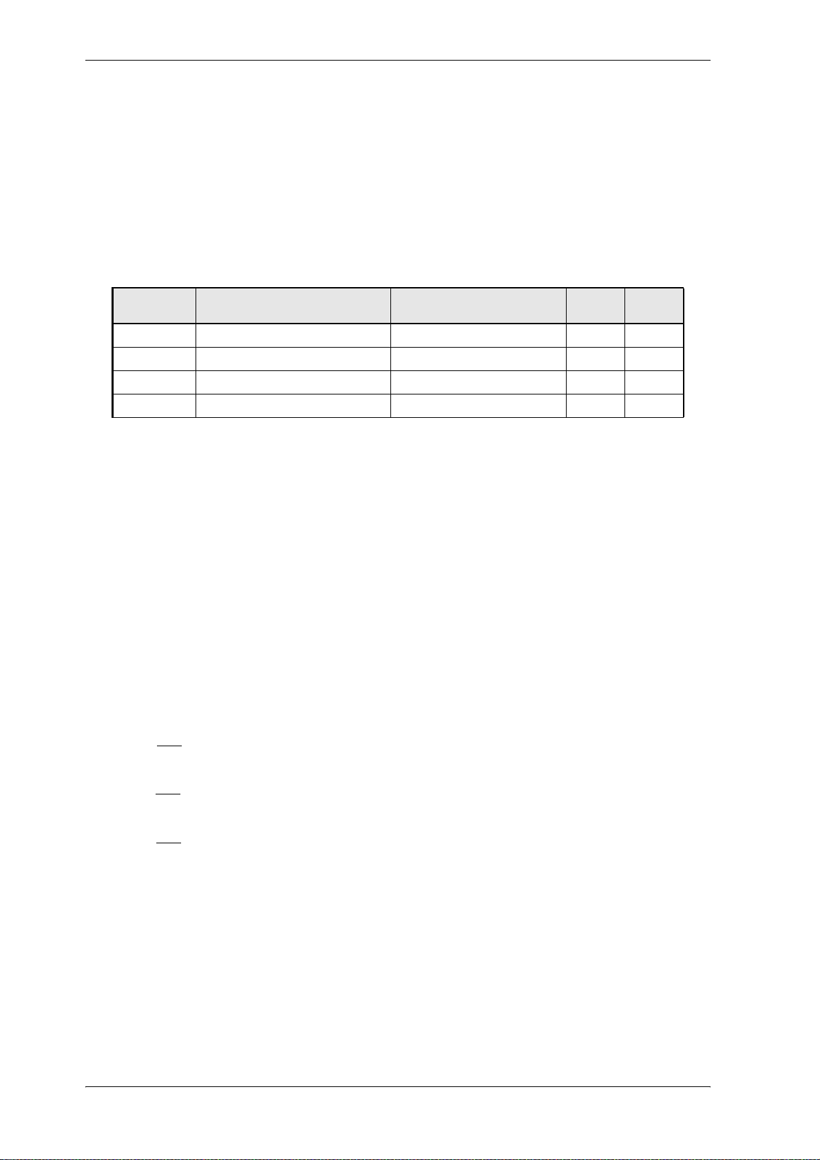
Parameter
7.4 Pulse Width Modulation
Function
The parameters of the pulse width modulation module serve to display the values supplied by the current
controller und the change of the PWM frequency.
Parameter overview
Parameter Name Range
P100 PWM phase L1 -100,00 ... +100,00 %
P101 PWM phase L2 -100,00 ... +100,00 %
P102 PWM phase L3 -100,00 ... +100,00 %
P103 PWM frequency 4,0 ... 8,0 kHz
Parameter description
P100 PWM phase L1
P101 PWM phase L2
P102 PWM phase L3
These parameters display the angle α of the relative power transistors for the individual phases.
This means: +100,00 % to a regulation angle of α = +100 %
0 to a regulation angle of α =0 %
-100,00 % to a regulation angle of α = -100 %
min. ... max.
Unit Display
only
!
!
!
The resultant voltage (middle values) at the power supply terminals can be calculated as follows:
PWM phaseL1 PWM phaseL2–
U
L12
U
L23
U
L31
-------------------------------------------------------------------------------------------
U
⋅ P610
ZK
U
⋅ P610
ZK
U
⋅ P610
ZK
maximum total range
PWM phaseL2 PWM phaseL3–
-------------------------------------------------------------------------------------------
maximum total range
PWM phase L3 PWM phase L1–
----------------------------------------------------------------------------------------------
maximum total range
P100 P101–
----------------------------------
⋅==
200 00 %,
P101 P102–
----------------------------------
⋅==
200 00 %,
P102 P100–
----------------------------------
⋅==
200 00 %,
Whereby UZK the intermediate circuit voltage is displayed via parameter P61 0. Due to the underlying cycle frequency this voltage cannot be measured on universal devices.
40 V-Controller (BUS 6 VC)
5.03047.01 Baumüller Nürnberg Electronic GmbH & Co. KG
Page 43
P103 PWM frequency
The frequency of the power unit is normally 8,0 kHz and can be changed to 4,0 kHz (values
between are not possible).
A change of the frequency is only permitted when pulses are inhibited.
After change of the freqency the parameter must be stored and the controller has to be
rebooted!
Parameter
NOTE
V-Controller (BUS 6 VC) 41
Baumüller Nürnberg Electronic GmbH & Co. KG 5.03047.01
Page 44

Parameter
7.5 Current Controller
Parameter overview
Parameter Name Bereich
min. ... max.
P080 I state 0,1 ... 63,9
P081 I P gain 0,0 ... 1000,0 ms
P034 MM clockwise rotating field 0 ... 1
P071 I Iq set value -100,00 ... 100,00 %
P072 I Iq actual value -199,99 ... 199,99 %
P068 I Iq controller output -100,00 ... 100,00 %
P069 I U mains pre-control -100,00 ... 100,00 %
P075 I Uq set value -100,00 ... 100,00 %
P077 I Id set value -100,00 ... 100,00 %
P078 I Id actual value -199,99 ... 199,99 %
P076 I Ud set value -100,00 ... 100,00 %
P070 I phase voltage L1 -100,00 ... 100,00 %
P086 I phase voltage L2 -100,00 ... 100,00 %
P073 I phase current L1 -100,00 ... 100,00 %
P074 I phase current L2 -100,00 ... 100,00 %
P083 I current offset L1 -25,00 ... 25,00 %
P084 I current offset L2 -25,00 ... 25,00 %
P099 I apparent current actual value 0,00 ... 100,00 %
Einheit nur
Anzeige
!
!
!
!
!
!
!
!
!
!
!
!
!
Parameter description
P080 I P gain
P081 I integral action time
This parameters set the P gain (kp) and the integral action time (TN) of the direct-axis current
controller and the wattless current controller.
Setting of the current controller:
If the motor parameter stator resistance and leakage inducta nce are known, the curre nt controller can be set the following way:
l
s
!
TnT
T
ab
The current controller is set according the absolute value optimum.
s
05
---- -
and k
r
S
1
---------------------- -
⋅,=
f
(P103)
S
l
S
----------------
P
3T
⋅
I
max
------------------------------------- -
⋅== =
U
ab
ZKnom
-------------------------------------
(P113)
(P087)
6
42 V-Controller (BUS 6 VC)
5.03047.01 Baumüller Nürnberg Electronic GmbH & Co. KG
Page 45
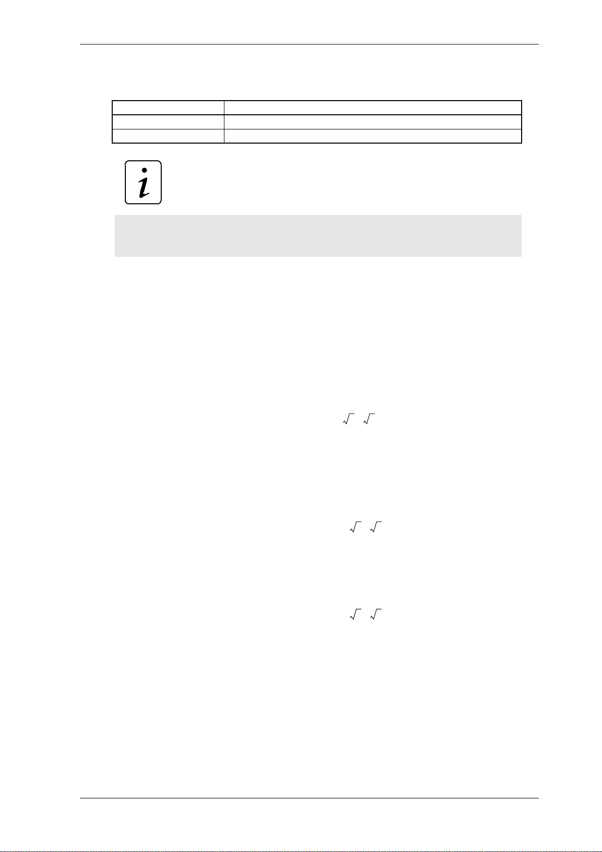
P034 MM clockwise rotating field
This parameter adapts the control to the motor´s rotating field.
Value Meaning
0 mains with counterclockwise rotating field (phase L2 and L3 changed)
1 mains with clockwise rotating field
NOTE
After changing the MM rotating field the data set 0 must be saved (boot data set) and the
controller must be re-booted!
Parameter
P071 I Iq
set value
P072 I Iq actual value
The cross current specified/actual value (active current component of the vector control) is
indicated here. 100 % corresponds to the value set in the LT I limit (P116).
P068 I I
controller output
q
Manipulated variable of active current controller.
Standardization: 100 % ↔
P069 I U mains pre-control
Pre-control of mains voltage (corresponds with the EMF of the motor).
Standardization: 100 % ↔ (effectiv e value)
P075 I U
set value
q
Sum of P068 Iq controller output and P069 U mains pre-control.
U
--------------------------------------
U
ZKnom
--------------------------------------
08, 32⋅⋅
ZKnom
32⋅
P087()
P087()
U
Standardization: 100 % ↔ (effectiv e value)
V-Controller (BUS 6 VC) 43
Baumüller Nürnberg Electronic GmbH & Co. KG 5.03047.01
--------------------------------------
08, 32⋅⋅
ZKnom
P087()
Page 46

Parameter
P077 I I
P078 I I
P076 I U
set value
d
actual value
d
The direct-axis current set value / actual value (reactive current component if the vector control) is displayed here.
Standardization: 100 % ↔ PU I limit (P116)
set value
d
Manipulated variable of direct-axis controller
.
Standardization: 100 % ↔ (effective value)
P070 I phase voltage L1
P086 I phase voltage L2
Voltage set values on unit‘s connection 1U1 and 1V1
Standardization: 100 % ↔ (effective value)
U
--------------------------------------
08, 32⋅⋅
U
--------------------------------------
08, 32⋅⋅
ZKnom
ZKnom
P087()
P087()
P073 I phase current L1
P074 I phase current L2
Standardization: 100 % ↔ PU I limit (P116)
P083 I current offset U
P084 I current offset V
To compensate the offset of the current transformer , the cu rrent transformer is set to 0 at ev ery pulse enabling. This parameter shows the offset value.
Standardization:
P099 I apparent current actual value
Standardization: 100 % ↔ PU I limit (P116)
100% ↔
211 (half of the measuring transducer range)
44 V-Controller (BUS 6 VC)
5.03047.01 Baumüller Nürnberg Electronic GmbH & Co. KG
Page 47
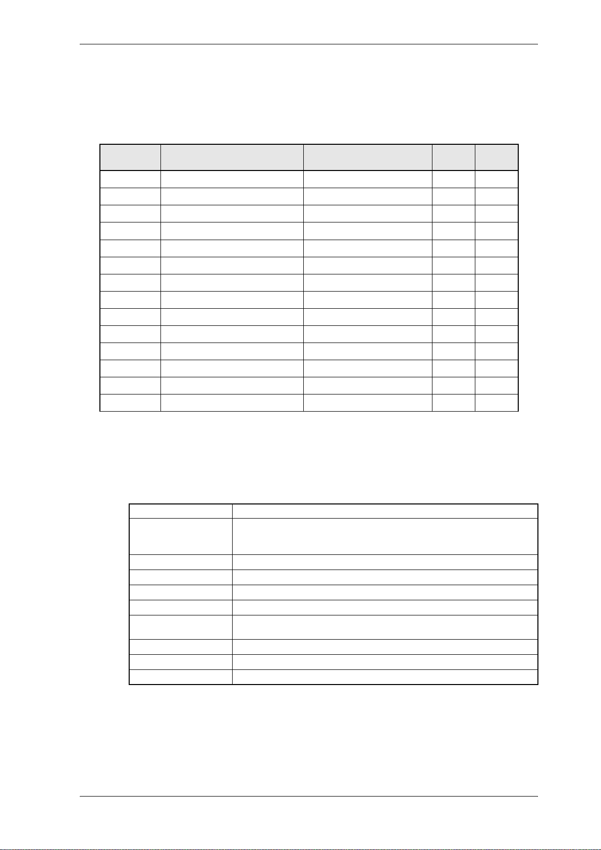
7.6 Uzk Controller (Uzk value setting)
Parameter overview
Parameter
Parameter Name Range
P059 N state 0000 ... FFFF
P057 N P gain 0,1 ... 1000,0
P058 N integral action time 0,0 ... 2000,0 ms
P087 ES UZK nominal value 280 ... 1000 V
P050 N Uzk set value 150,0 ... 999,9 V
P047 N Uzk additional set value -10,00 ... 10,00 V
P204 N Uzk set value max. 550,0 ... 999,9 V
P205 N Uzk set value min. 150,0 ... 950,0 V
P051 N Uzk actual value -1999,9 ... 1999,9 V
P052 N Uzk controller output -100,00 ... 100,00 %
P054 N I max. feed back current/IR1 0,00 ... 100,00 %
P055 N I max. feed-in current/IR2 0,00 ... 100,00 %
P060 N Uzk control deviation -199,99 ... 199,99 %
P061 N Uzk limit control deviation 0,00 ... 199,99 %
Parameter description
min. ... max.
Unit Display
only
!
!
!
P059 N state
This parameter shows the Uzk controller´s state.
P057 N P gain
P gain (Kp) of Uzk controller.
Bit no. Meaning
0 ... 2
3
4
5 ... 9
10
11
12
13
14 ... 15
000: STOP, N Uzk controller is disabled
001: RUN, N Uzk controller is enabled
011: STAND_BY, N-Uzk controller is disabled
1: error in module, error code see P124
reserved
reserved
reserved
0: current direction 1 active
1: current direction 2 active
1: set value reached (|deviation P060| < limiter deviation (P061)
1: limiter set value reached (current limiter)
reserved
V-Controller (BUS 6 VC) 45
Baumüller Nürnberg Electronic GmbH & Co. KG 5.03047.01
Page 48

Parameter
P058 N integral action time
Integral action time (TN) of Uzk controller.
P087 ES Uzk nominal value
This parameter sets the nominal intermediate circuit voltage set value of the BUC.
P047 N Uzk additional set value
P050 N Uzk set value
This parameter sets the intermediate circuit voltage.
P051 N Uzk actual value
Actual value of the intermediate circuit voltage.
P052 N Uzk controller output
This parameter displays the set value of the Uzk controller .
P054 I max. feed back current
Limiter of the maximum feed back mains current
P055 I max. feed-in current
Limiter of the maximum feed-in (supply) mains current.
P060 N Uzk control deviation
This parameter displays the control deviation of the Uzk controller at the mome nt.
P061 N Uzk limiter control deviation
If the value falls below the maxim um deviation set by this parameter, the function module
transmits the message set value reached (bit no. 12 in N state P059 is set).
P204 N Uzk set max.
Limiter of the maximum intermediate circuit voltage set value.
P205 N Uzk set min.
Limiter of the maximum intermediate circuit voltage set value.
46 V-Controller (BUS 6 VC)
5.03047.01 Baumüller Nürnberg Electronic GmbH & Co. KG
Page 49
Parameter
7.7 Drive Manager (Enable the Controller)
Function
The drive manager administrates the essential system resources of the drive. These include among
others complete unit control in various modes, switching between the different modes, the management
of all communication interfaces, error treatment etc.
Parameter overview
Parameter Name Range
min. ... max.
P120 M control word 0000 ... FFFF
P121 M state word 0000 ... FFFF
P122 M set operation mode -6 ... 6
P123 M actual operation mode -6 ... 6
P124 M error code 0000 ... FFFF
P125 M error index 0 ... 31
P136 M mode 0000 ... 0007
P126 M communication source 0000 ... 000F
P127 M communication monitoring 0000 ... 000F
P128 M monitoring time 0 ... 60 000 ms
P137 M state 1 0000 ... FFFF
Unit Display
only
!
!
!
!
!
V-Controller (BUS 6 VC) 47
Baumüller Nürnberg Electronic GmbH & Co. KG 5.03047.01
Page 50

Parameter
! Unit control states
NOT READY TO START
0
– electronics supplied with voltage
– self-test running
– initialisation running
– Uzk control is disabled
– relay „ready for use“ is OFF (relay is fallen off - BUC is not ready)
INHIBIT START
1
– software/hardware initialisation completed
– Uzk control is disabled
– main contactor is not enabled (internal contact between X1:6 and X1:7 open, see terminal dia-
gram BUC)
– charge circuit can be activated (power on - see terminal diagram BUC63), the intermediate circuit
can be charged
– relay „ready for use“ is OFF (relay is fallen off - BUC is not ready)
READY TO START
2
– intermediate circuit voltage has reached the value set in P600, no flow of charge current
– Uzk controller is disabled
– main contactor is enabled (internal contact betwe en X1:6 and X1:7 closed, see terminal diagram
BUC)
– main contactor is activated
– timer with set main contactor switching time (P601 MC switching time) is started
– relay "ready for use" is OFF (relay is fallen off - BUC is not ready)
SWITCHED ON, wait for pulse enable
9
– intermediate circuit voltage has reached set value P600
– Uzk control is disabled
– main contactor switched, the main contactor switching time runs up (P601 MC switching time)
– mains voltage lays on the BUC power unit, the controller is synchronous with the mains
– signal "ready for pulse enable" is enabled (see X26:22, terminal diagram V-controller
– relay "ready for use" is OFF (relay is fallen off - BUC is not ready)
SWITCHED ON, wait until pre-control time (P602)has run down
3
– pulses are enabled (see X26:14, terminal diagram V-controller)
– Uzk control is enabled
– timer with set pre-control time (P602) is started and the intermediate circuit voltage is increased
to set Uzk nominal value (P087)
– relay "ready for use" is OFF (relay is fallen off - BUC is not ready)
ENABLE OPERATION
4
– Uzk control is enabled
– intermediate circuit voltage has reached Uzk nominal value (P087)
– relay "ready for use" is ON (relay is closed - BUC is ready)
48 V-Controller (BUS 6 VC)
5.03047.01 Baumüller Nürnberg Electronic GmbH & Co. KG
Page 51

Parameter
FAULT REACTION ACTIVE
E
– Uzk control is disabled
– main contactor is switched off (BUC contact between X1:6/X1:7 is opened)
– relay "ready for use" is OFF (relay is fallen off - BUC is not ready)
FAULT
F
– Uzk control is disabled
– main contactor is switched off (BUC contact between X1:6/X1:7 is opened)
– drive controller expects the error acknowledgement (see X2 6:17, te rmin al d iag ra m V-contro ller)
Unit control states:
– content of control and state word
– switching state of the "ready for use" relay
Unit control
state
0 initialization phase initialization phase OFF
1 0x000A 0x0060 OFF
2 0x000E 0x0021 OFF
9 0x000E 0x0021 OFF
3 0x000E 0x0033 OFF
4 0x000F 0x0437 ON
E 0x000E 0x0028 OFF
F 0x000E 0x0028 OFF
P120 M control word P121 M state word Switching state
"ready for use"
relay
V-Controller (BUS 6 VC) 49
Baumüller Nürnberg Electronic GmbH & Co. KG 5.03047.01
Page 52
Parameter
P120 M control word
This parameter corresponds to DRIVECOM object 6040
trol unit state machine.
Bit no. Name Comment
0 switch on
1 inhibit voltage
2 wait for pulse enable
3 operation enabled,
4.. 6 reserved
7 reset error
8...15 reserved
(state "9")
pulses enabled
and is the input word of the con-
hex
NOTE
When P126 (comm. source) is unequal 0 the controller can only be enabled with a hardware pulse enable first (high signal on input X26:14, see terminal diagram V-cont roller)
and after that the parameter P120 (state word) must be set to 0x000F.
The error memory is resetted by writing on the value 0x0080 on P120 (state word). This
command is only executed after the hardware pulse enable is disabled (low signal on input
X26:14, see terminal diagram V-controller).
50 V-Controller (BUS 6 VC)
5.03047.01 Baumüller Nürnberg Electronic GmbH & Co. KG
Page 53
P121 M state word
This parameter corresponds to DRIVECOM object 6041
control state machine.
Bit no. Name Comment
0 READY TO START
1 SWITCHED ON
2 OPERATION ENABLED,
3 FAULT
4 Uzk control is enable
5 always 1
6 INHIBIT START
7...9 reserved
10 set value reached
11...15 reserved
pulses enabled
Parameter
and is the output word of the unit
hex
NOTE
After enabling the controller the value of parameter P121 (state word) changes from
0x0021 to 0x0033. If the set voltage is reached the "read y for use" relay is enabled and the
parameter P121 is set to 0x0437.
V-Controller (BUS 6 VC) 51
Baumüller Nürnberg Electronic GmbH & Co. KG 5.03047.01
Page 54
Parameter
P122 M set operation mode
Operation
mode
-3 Uzk controller not changeable
P123 M actual operation mode
This parameter displays the active operation mode.
P124 M error code
In case of a fault, the corresponding error code can be found here. This error is a cknowledged
if the bit „reset fault“ in the control word (P120) is set from 0 to 1 or the input „error reset“ is
enabled (see P136 M mode).
If several errors are present, the next error is displayed immedi ately after acknowledgeme nt.
Error codes see chapter maintenance, error messages.
P125 M error index
This parameter indicates the number of errors which are present. On acknowledgement of
each error the displayed value is decreased. The parameter co ntains the number 0 after ack
nowledging all errors.
Mode Comment
-
P136 M mode
This parameter chooses the different options to acknowledge an error message (see V-cont troller terminal diagram). The error acknoledgement can be done via digital input 3 X26:17
DELETE ERROR.
Bit no. Meaning
1 ... 15 reserved
P137 M state 1
Bit no. Meaning
6 ... 15 reserved
0 0: errors are acknowledged individually with bit no. 7 0 → 1
1: errors are acknowledged in one go with bit no. 7 0 → 1
0 ... 3 Shows the state number displayed in the 7 segment display
4, 5 00: drive displays no error
01: error has occurred, error reaction is set in P189
52 V-Controller (BUS 6 VC)
5.03047.01 Baumüller Nürnberg Electronic GmbH & Co. KG
Page 55
P126 M communication source
This parameter sets the communication source.
Bit no. Meaning
0 0: controlling the unit only by hardware signals (PE)
1: BASS protocol via RS 232 enabled
1 ... 15 reserved
If the parameter „communication source“ is set to 0, the drive can only be contro lled via pulse
enabling (PE).
If P126 = 1, the controller is only enabled when first the hardware pulse enable is given ( high
signal on input X26:14, see terminal diagram V-controller) and then P120 (state word) is set
to value 0x000F.
The parameters M communication source (P126) and DSM command (P190) can be changed always with service interface and dual port RAM interface (BASS protocol, operation pro gram).
Parameter
P127 M communication monitoring
Monitoring of the sources of communication can be activated via this parameter.
Bit no. Meaning
0 1: BASS protocol via RS 232 is monitored
1 ... 15 reserved
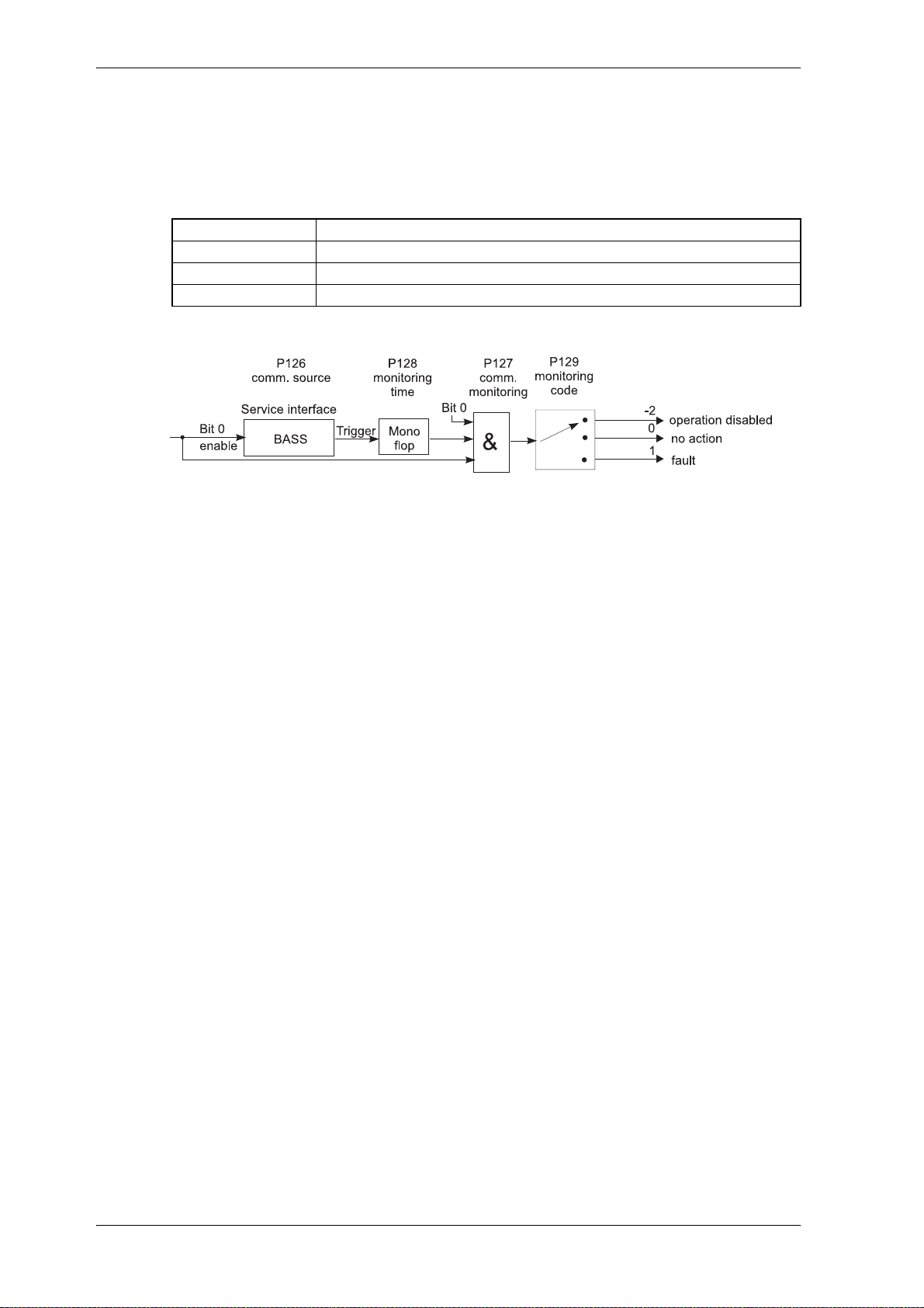
P128 M monitoring time
This parameter sets the time constant of communication monitoring. It is valid for all sources
of communication.
If no information from the current communication source is received within the period set in
the parameter „monitoring time“, e.g. as a result of an open circuit on an interface cable or
defective communication card, the action selected in the parameter „mo nitoring selection co
de“ is carried out. Monitoring time can be up to one minute with the representation unit being
1 ms. If the time 0 ms is entered, monitoring is switched off.
If the controller is operated without communication (P126 = 0), monitoring time must be set
to 0 ms.
-
V-Controller (BUS 6 VC) 53
Baumüller Nürnberg Electronic GmbH & Co. KG 5.03047.01
Page 56
Parameter
P129 M monitoring code
This parameter determines the drive reaction in the event of the communication monitoring
time being exceeded.
Selection mode Function
0 no action
-2 controller is disabled (controller state changes from state 4 to state 9)
1 controller changes to state FAULT (E/F)
54 V-Controller (BUS 6 VC)
5.03047.01 Baumüller Nürnberg Electronic GmbH & Co. KG
Page 57
7.8 New BUC Parameter
Parameter overview
Parameter
Parameter Name Range
min. ... max.
P600 M Uzk threshold 117 .... 1000 V
P601 M MC switching time 10 ... 10000 ms
P602 M pre-control time 1 ... 10000 ms
P610 MM Uzk actual 117 ... 1000 V
P611 MM Uzk actual smoothed 117 ... 1000 V
P612 MM Uzk filter time 0,0 ... 200,0 ms
P616 BUC control word 0000 ... FFFF -
P617 MM CC counter 0 ... 65535 -
P618 MM period time mains 0,000 ... 65,535 ms
P619 MM period smoothed 0,000 ... 65,535 ms
P620 MM PLL display smoothing 0,000 ... 1000,0 ms
P621 MM mains frequency 0,00 ... 655,35 Hz
P622 MM no. of mains faults -32767 ... 32767 -
P623 MM mains jitter -180,0 ... 180,0 Grad
P624 MM jitter limit 0,0 ... 30,0 Grad
P625 MM Rho offset 0,0 ... 200,0 ms
P626 MM Rho -32767 ... 32767 -.
P627 I current delta_max -100,00 ... 100,00 %
Unit Display
only
!
!
!
!
!
!
!
!
!
!
!
P628 I delta ISQ -199,99 ... 199,99 %
P629 I delta ISD -199,99 ... 199,99 %
P630 I IQ set smoothing time 0,0 ... 500,0 ms
P631 MM U mains alpha -199,99 ... 199,99 %
P632 MM U mains beta -199,99 ... 199,99 %
P633 MM mains voltage eff. 0,0 ... 640,0 V
P634 MM effective power -3276,7 ... 3276,7 kW
Parameter description
P600 M Uzk threshold
Reaches the intermediate circuit voltage the set value during the charging and P623 (mains
jitter) < P624 (jitter limit), the main contactor is enabled (charging finished).
P601 M MC switching time
This time is started after the contactor is switched on. If this tim e is run up th e digital output 2
(X26:22 ready for pulse enable) changes to high.
!
!
!
!
!
!
V-Controller (BUS 6 VC) 55
Baumüller Nürnberg Electronic GmbH & Co. KG 5.03047.01
Page 58

Parameter
P602 M pre-control time
After the pulse enable is given this time is started. After this time is run up the "ready for use"
relay is enabled. This is independent wether the intermediate circuit voltage ha s reached the
desired Uzk set value (P087 Uzk nominal).
P610 MM Uzk actual
Actual value of the intermediate circuit voltage.
P611 MM Uzk actual smoothed
Actual value intermediate circuit voltag e s mo o thed. The smoothing time constant of a digital
PT1 can be set in parameter P612 (MM Uzk smoothing time).
P612 MM Uzk smoothing time
To reduce interferences on the intermediate circuit voltage actual value a smoothing constant
of a digital PT1 can be set here.
P616 BUC control word
This parameter displays the state of the PLL.
Bit no. Meaning
0 0 : PLL catch phase
1 : normal run after PLL caught
1 1 : set, when PLL not caught
2 1 : set, when no error
3 1 : error in current controller
4 ... 15 reserved
P617 MM CC counter
The no. of whole control periods (control tasks) are count here. The counter "CC counter" is
incremented with each control period. While comparing with the last maximum mains period
value, an exceed of the jitter limit is checked. In this case, the error counter increases and the
previous mains period value is used. Therefore the internal value of the mains angle increa
ses steadily.
P618 MM period time mains
The measured mains period is displayed.
-
P619 MM period smoothed
The smoothed value of the mains period is displayed. The smoothing can be set with P620
(MM PLL display filter).
P620 MM PLL display filter
The measured duration of the mains period is smoothed and displayed here.
56 V-Controller (BUS 6 VC)
5.03047.01 Baumüller Nürnberg Electronic GmbH & Co. KG
Page 59

P621 MM mains frequency
Display of the measured mains frequency.
P622 MM no. of mains faults
No. of not successful mains synchronisations because of faults. Reaches the error counter
the value 5, the bit no. 1 in P616 (BUC control word) is set, the drive manager disables the
controller and the error 0x0503 is generated.
P623 MM mains jitter
Set/actual deviation of 2 successive mains values (deviation of period length, display in degrees).
P624 MM mains jitter limit
If the absolute value of the phase deviation during synchronisation to the mains is below the
set mains jitter limit, the period time is new calculated and therefore all angles until the next
occurance are calculated. Moreover the error counter P622 (MM no. of mains faults) is de
cremented until min. zero. If the absolute value is higher than the mains jitter limit, the error
counter is incremented (until max. 5) and when the controller is enabled (state 3 and 4) the
error 0x0503 is generated. If the controller is disabled, the controller change s fr om state 9 to
state 2. The signal of the function ou tput 2 (X26:22, see chapter 4.4 - terminal diagram Vcontroller) "ready for pulse enable" changes from high to low.
Parameter
-
P625 MM Rho offset
Because of the phase shift when measuring the "SYNC" signal a correction value is added
thereby the transformation angle is main s sync hron. The parameter must be set in this way,
that P076 (Ud set value) is equal zero, when controller is enabled.
P626 MM Rho
Actual value of the mains angle (transformation angle).
Internal standardization: ± 180 degrees ↔ ± 32767
V-Controller (BUS 6 VC) 57
Baumüller Nürnberg Electronic GmbH & Co. KG 5.03047.01
Page 60

Parameter
P627 I current delta max
Exceed the absolute value of the control deviation the value set with this parameter, bit no. 3
ist set in parameter P616 (BUC control word).
No error is generated!
P628 I delta ISQ
This parameter displays the control deviation of the active current controller (IQ).
Standardization: 100 % ↔ P116 (PU I limit)
P629 I delta ISD
This parameter displays the control deviation of the reactive current controller (ID).
NOTE
Standardization: 100 % ↔ P116 (PU I limit)
P630 I IQ set smoothing time
Active current set value (IQ) smoothing. The time constant of a digital PT1 can be set here.
P631 MM U mains alpha ( cos(ωt) )
U mains alpha = U
The value of the mains phase to phase voltage is displayed.
Standardization: 100 % ↔ 1000 [V]
L12
P632 MM U mains beta ( sin(ωt) )
2–
U mains beta = U
The value of the mains phase to phase voltage is displayed.
Standardization: 100 % ↔ 1000 [V]
-------
L13
3
-------
+ U
1
L12
3
P633 MM mains voltage eff.
The effective value of the mains phase to phase voltage is displayed.
P634 MM e ffective power
The smoothed value (265 ms) of the effective power ( (+) taken from the mains or (-) feed
back power).
58 V-Controller (BUS 6 VC)
5.03047.01 Baumüller Nürnberg Electronic GmbH & Co. KG
Page 61
Parameter
7.9 Data Set Management
Function
Data sets can be loaded from EPROM, changed and saved. 4 data sets can be managed at e very time.
! After switching on (booting)
Directly after switching on the operating voltage sup ply the DSM (da ta set mana gement) au tomatically loads the boot data set (data set 0) into the drive's user memory.
After successful execution of this command the DSM stops in
state 0003: STAND_BY (P191)
message 0000: no error (P192).
If no boot data set has been created yet, the DSM is in
state 000B: STAND_BY with error (P191)
message 0002: data set not available (P192).
In addition to the drive managers state changes to „F“ fault and parameter M error co de (P124) dis-
plays the error code 0902.
! Creating and updating a boot data set
NOTE
Prior to any new action the DSM (data set management) must first be reset by the command 0:
Reset (P190)
This measure sets all DSM parameters to value 0. This also refers to data set name (P193) and data
set version (P194), which in this state represent the boot data set.
It must now be set via the command 5: write data set into EEPROM (P190) how the boot data set is
to be created for the first time in EEPROM or how an existing boot data set is to be updated.
Only in the case of message 0000: no error (P192) and DSM state 0003: STAND_BY is the data set
been written correctly.
1)
The counter „DS program cycle“ (P197) is increased by 1.
! Creating and updating other data sets
The procedure is identical to that of creating and updating a boot data set except that the parameter
data set name (P193) can now be selected from numbers 1 to 2.
1)
Data sets can be transmitted to the working memory with command 6: read data set from EEPROM
(P190).
Only in the case of DSM message 0000: no error (P192) and DSM state 0003: STAND_BY has the
data set been written correctly.
V-Controller (BUS 6 VC) 59
Baumüller Nürnberg Electronic GmbH & Co. KG 5.03047.01
Page 62

Parameter
! Source load of the parameters
If a source load is carried out the standard values of the parameter list are set and therefore a defined
state is reached.
The procedure of the source load is mentioned below:
1. P190 = 0 command reset data set management
2. P190 = 7 command delete data set
3. Wait until P191 = 0003
4. Switch off power supply of controller
5. Switch on power supply of controller
6. Now is displayed: P191 = 000B stand-by with error
P192 = 0002 data set not available
P124 = 0902
The controller´s state is fault
7. P190 = 0 command reset data set management
8. P190 = 5 command store data set
9. Wait until P191 = 000B
! Store the write protected data set
1. P190 = 0 command reset data set management
2. P190 = 8 command input password
3. P190 = password 1
4. P190 = 0 command reset data set management
5. P193 = 3 DS no. write-protected data set
6. P190 = 5 command store data set
! Change article no. of data set
1. P190 = 0 command reset data set management
2. P190 = 8 command input password
3. P190 = password 2
4. P190 = 0 command reset data set management
5. P193 = 0, 1, 2, (3)* data set no.
6. P194 = new article no. hexadecimal number
7. P190 = 5 command store data set
* only possible, if password 1 was already given
60 V-Controller (BUS 6 VC)
5.03047.01 Baumüller Nürnberg Electronic GmbH & Co. KG
Page 63
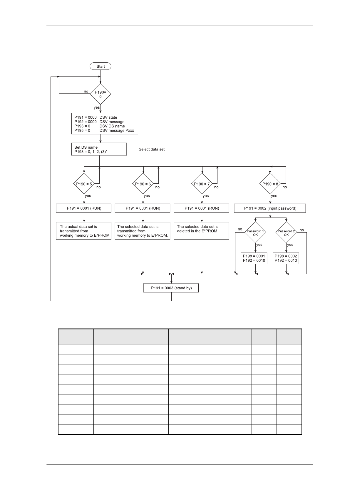
Overview of the commands
Parameter
Parameter overview
Parameter name Range
min. ... max.
P190 DSM command 0 ... 8 0
P191 DSM state 0000 ... FFFF
P192 DSM message 0000 ... FFFF
P195 DSM message Pxxx 0 ... 700
P193 DSM DS name 0 ... 3
P194 DSM DS article no. 0000 0000 ... FFFF FFFF
P197 DSM DS program cycles 0 ... 65536
P196 DSM load data set 0 ... 3
P198 DSV key 0000 ... 0003
V-Controller (BUS 6 VC) 61
Baumüller Nürnberg Electronic GmbH & Co. KG 5.03047.01
Unit Display
only
!
!
!
!
!
!
Page 64
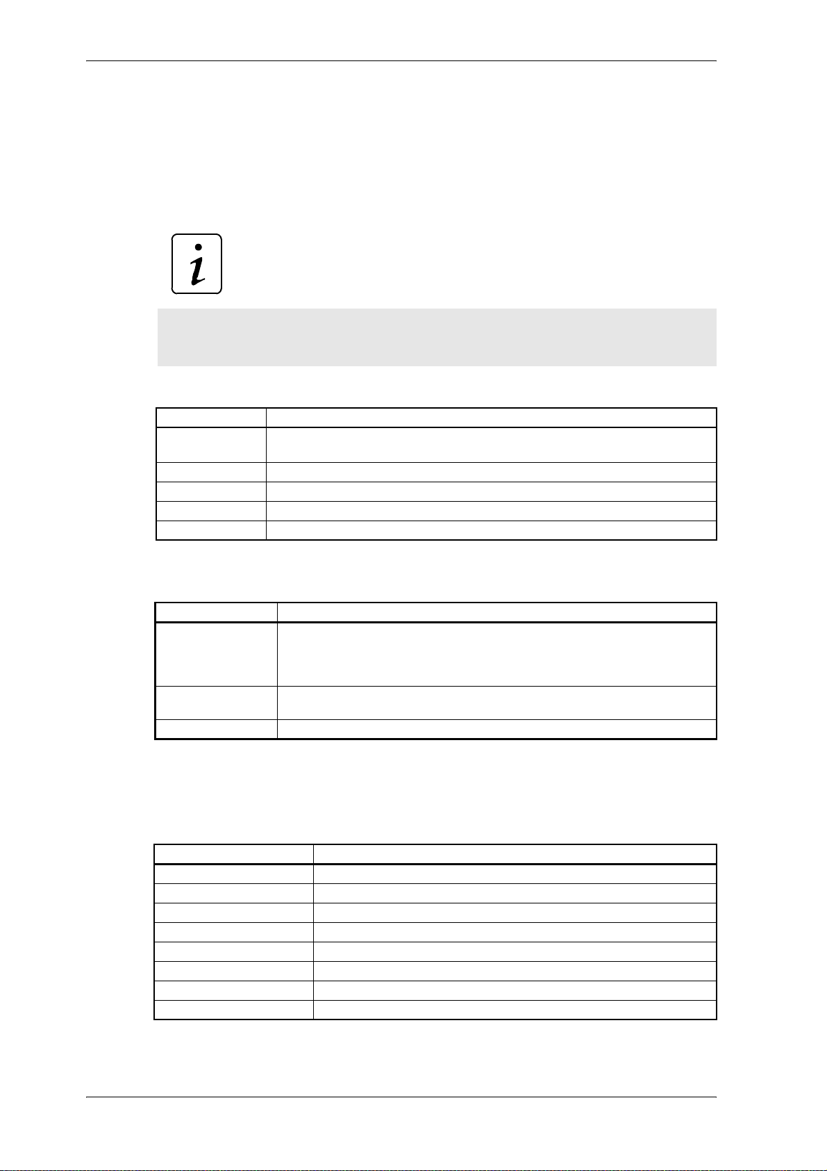
Parameter
Parameter description
P190 DSM command
This command instructs the data set management to load, to save and to delete an existing
data set.
This parameter is independent of the parameter M communication source (P126) always
changeable.
Command Meaning
0 reset of data set management
5 save data set from user memory to EEPROM
6 load data set from EEPROM to user memory
7 delete EEPROM data set
8 input password
NOTE
The parameter P191 till P195 are set automatically to 0.
P191 DSM state
Bit no. Meaning
0 ... 2 000 : STOP Data set management is ready for a command or for changing data
3 1 : An error has occurred in the data set management.
4 ... 15 reserved
P192 DSM message
If a message occurs during the implem entation o f a command, it is d isplayed in th is param eter.
Bit no. Meaning
0 1: undefined command
1 1: data set not available
2 1: wrong check sum
3 1: parameter not changeable
4 reserved
5 1: memory full
6 1: error in configuration list
7 1: undefined parameter format
sets.
001 : RUN Data set management is processing a command.
011 : STAND_BY Data set management has finished a command.
Error code see P124, M error code and P192, DSM message
62 V-Controller (BUS 6 VC)
5.03047.01 Baumüller Nürnberg Electronic GmbH & Co. KG
Page 65
P195 DSM message Pxxx
If a message has occurred (P192 ≠ 0), this parameter shows the parameter no. involved.
P193 DSM DS name
A maximum of 4 data sets can be managed in each memory area. They are selected via the
parameter „data set name“.
Value Memory range EEPROM (non-volatile)
0 data set 0 (boot data set)
1 data set 1
2 data set 2
3 data set 3 (write-protected data set)
P194 DSM DS article no.
Article no. of a data set ex factory.
Parameter
P197 DSM DS program cycles
Number of write actions on this data set.
P196 DSM load data set
The data set with the corresponding number (0...2) can be loaded from the EEPROM into the
working memory via this parameter.
The following procedure should be adhered to:
! Firstly, ensure that the status of the data set management (P191) is either set to 0
(STOP) or to 0003 (STAND_BY).
! Next enter the number of the required da ta set in the param eter, P196 (DSM loa d data
set).
! All further steps follow independently:
– The number of the required data set is displayed in parameter P193.
– The command 6 „load data set from EEPROM into user memory“ is visible in the pa-
rameter P191 (DSM command).
– The data set is loaded.
! The procedure is completed once the DSM status displays again state 0003
(STAND_BY).
(Incidentally entered numbers should be ignored.)
V-Controller (BUS 6 VC) 63
Baumüller Nürnberg Electronic GmbH & Co. KG 5.03047.01
Page 66
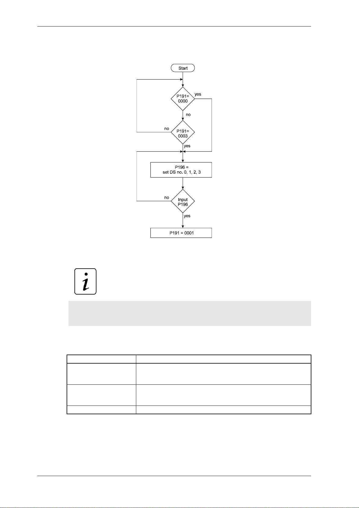
Parameter
Change data set via P196
The time in which this procedure is carried out will differ according to the loading of the microprocessor.
This parameter can be used to change data sets via digital inputs. A chan ge over must not
be executed if controller is enabled!
P198 DSM key
NOTE
Bit no. Meaning
0 0: Data set 3 is write-protected
1: Data set 3 is write-enabled
(only after input of password 1)
1 0: The article no. of all data sets is write-protected
1: The article no. of all data sets is write-enabled
(only after input of password 2)
2 ... 15 reserved
64 V-Controller (BUS 6 VC)
5.03047.01 Baumüller Nürnberg Electronic GmbH & Co. KG
Page 67
7.10 Operation System
Parameter overview
Parameter
Parameter Name Range
P138 Language 0 ... 4
P166 OS state 0000 ... FFFF
P162 OS message 0 ... 9999
P161 OS sampling time 124,8 ... 4000,0 µs
P174 OS user software 0 ... 99
P163 OS BUS6-VC SW release 0,00 ... 99,99
P160 OS selection 0 ... 1000
P169 OS value 0 ... 65535
Parameter description
P138 Language
Here you can set the language for parameter text.
Value Language
1 German
2 English
3 reserved
4 reserved
min. ... max.
Unit Display
only
!
!
!
!
P166 OS state
This parameter displays the state of the function module operation systems.
Bit no. Meaning
0 ... 3 1: operation system runs
4 ... 11 reserved
12 1: main program cycle time exceeds maximum value
13 1: task calculation time has exceeded maximum value
14 ... 15 reserved
P162 OS message
This parameter shows the number of operation system errors.
P161 OS sampling time
The system clock shows the run interval of the shortest operation system time slot.
V-Controller (BUS 6 VC) 65
Baumüller Nürnberg Electronic GmbH & Co. KG 5.03047.01
Page 68
Parameter
P174 OS user SW
Value Meaning
0 production run software
>0 user fitted software
P163 OS BUS6-VC SW release
This parameter displays the software release of the controller.
P160 OS selection
P169 OS value
With this parameter different measured values can be read from operation system.
Selection P160 Value P169 Unit
4 Maximum value of main program cycle time
(The maximum value memory can be reset through writing on)
40 Actual measured values of main program cycle time [1 ms]
5 16 bit counter for main program cycles [1]
[1 ms]
66 V-Controller (BUS 6 VC)
5.03047.01 Baumüller Nürnberg Electronic GmbH & Co. KG
Page 69
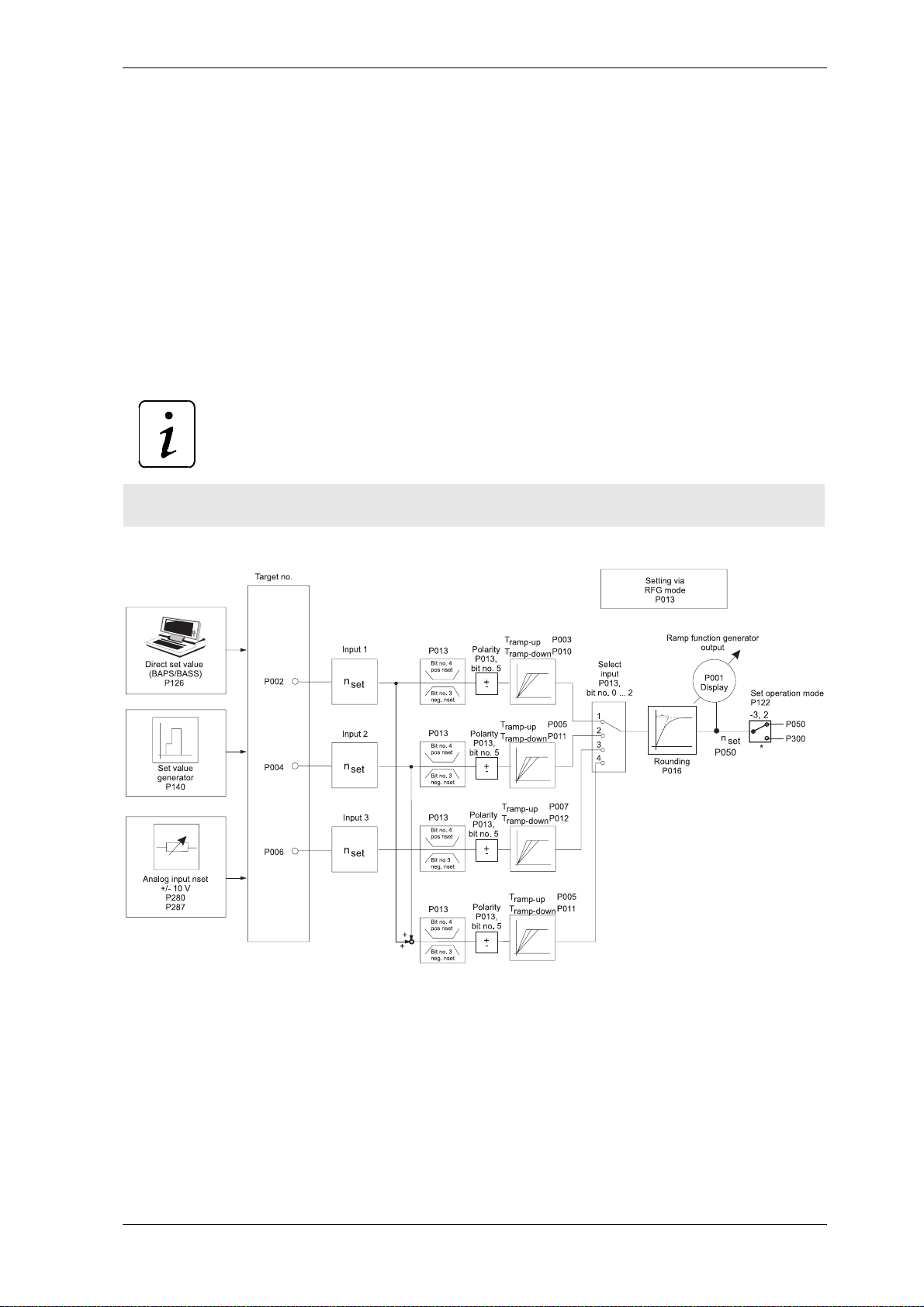
Parameter
7.11 Ramp Function Generator
Function:
The ramp function generator (RFG) manages the 4 set value inputs, which can alternatively be switched
to the output. The ramp-up and ramp-down times can be set separately for each input.
(If set to STOP by means of P013, only the ramp-down time can be adjusted)
All inputs and the output of the ramp function generator are relative parameters (± 1 00 %) and standardized to maximum speed (P019).
The ramp steepness for the acceleration and braking procedures are determined by the ramp-up and
ramp-down times. The times thus refer to 100 % set value alteration.
NOTE
If the inputs are used für intermediate circuit voltage 100 % ↔ 1000 V.
V-Controller (BUS 6 VC) 67
Baumüller Nürnberg Electronic GmbH & Co. KG 5.03047.01
Page 70
Parameter
Parameter overview:
Parameter Name Range
P014 RFG state 0000 ... FFFF
P013 RFG mode 0000 ... 007F
P002 RFG input 1 -100,00 ... 100,00 %
P004 RFG input 2 -100,00 ... 100,00 %
P006 RFG input 3 -100,00 ... 100,00 %
P003 RFG ramp-up time 1 0,00 ... 650,00 s
P010 RFG ramp-down time 1 0,00 ... 650,00 s
P005 RFG ramp-up time 2 0,00 ... 650,00 s
P011 RFG ramp-down time 2 0,00 ... 650,00 s
P007 RFG ramp-up time 3 0,00 ... 650,00 s
P012 RFG ramp-down time 3 0,00 ... 650,00 s
P016 RFG rounding 0 ... 60000 ms
P001 RFG output -100,00 ... 100,00 %
Parameter description
min. ... max.
Unit Display
only
!
!
P014 RFG state
Displays the function module´s state.
Bit no. Meaning
10 ... 11 reserved
13 ... 15 reserved
0 ... 2 000: STOP 001: RUN
3 1: error in function module, error code see M error code (P124)
4 1: RFG output is set internally to 0 (RFG_LOCKED)
5 1: RFG was stopped on the ramp (RFG_STOP)
6 1: RFG input is set internally to set value 0 (RFG_ZERO)
7 reserved
8 1: ramp-up procedure is active
9 1: ramp-down procedure is active
12 1: RFG output = RFG input (set value reached)
68 V-Controller (BUS 6 VC)
5.03047.01 Baumüller Nürnberg Electronic GmbH & Co. KG
Page 71
P013 RFG mode
The input selection chooses one out of four inputs of the ramp function generator and activates the set value limitation.
Bit no. Meaning
0 ... 2 000: reserved
6 ... 15 reserved
P002 RFG input 1
Parameter
001: input 1
010: input 2
011: input 3
100: sum of input 1 and input 2
3 1: negative set values are disabled
4 1: positive set values are disabled
5 1: change polarity of actual set value
NOTE
The value of P002 (RFG input) is changed automatically, when writing on P087 (PS Uzk nominal).
P004 RFG input 2
P006 RFG input 3
All 3 inputs are balanced and can be written via the serial interface, position controller and
the set value generator as well as the analog set value input.
P003 RFG ramp-up time 1
P005 RFG ramp-up time 2
P007 RFG ramp-up time 3
The acceleration assigned to the inputs can be set via the ramp-up times. The time selected
here correspond to a set value alteration of 100 %.
P010 RFG ramp-down time 1
P011 RFG ramp-down time 2
P012 RFG ramp-down time 3
The deceleration assigned to the inputs can be set via the ramp-down times. The time selected here correspond to a set value alteration of 100 %.
P016 RFG rounding
A first-order time delay element is imple m en te d in or de r t o ro u nd of f ra m p co rn e rs. Th e time
constants of the PT
V-Controller (BUS 6 VC) 69
Baumüller Nürnberg Electronic GmbH & Co. KG 5.03047.01
device can be set by this parameter.
1
Page 72

Parameter
P001 RFG output
This parameter displays the actual output value.
70 V-Controller (BUS 6 VC)
5.03047.01 Baumüller Nürnberg Electronic GmbH & Co. KG
Page 73
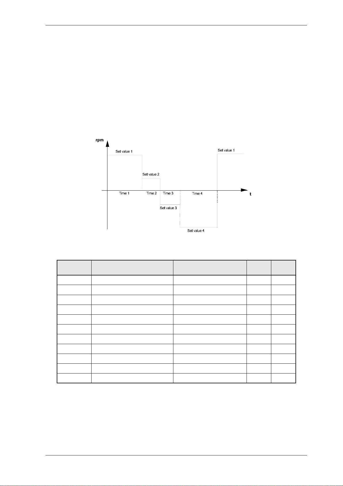
Parameter
7.12 Set Value Generator
Function
The module creates a plateau set value for each of the 4 ti me zones. Both the plateau amplitude and the
output time interval per zone can be allocated parameters. The amplitudes are relative and are standar
dised by means of the min./max. receiver values. On termination of the last time zone the first time zone
starts again. Each time the controller is enabled the set value generator is newly started in zone 1. When
leaving the state „operation enabled“ (P121), the set value generator is stopped.
Thus e.g. the following speed set value graph can be created:
-
Parameter overview
Parameter Name Range
P150 SVG state 0000 ... FFFF
P140 SVG target Pxxx 0 ... 700
P141 SVG output - 100,00 ... + 100,00 %
P142 SVG set value 1 - 100,00 ... + 100,00 %
P143 SVG set value 2 - 100,00 ... + 100,00 %
P144 SVG set value 3 - 100,00 ... + 100,00 %
P145 SVG set value 4 - 100,00 ... + 100,00 %
P146 SVG time 1 0,001 ... 60,000 s
P147 SVG time 2 0,001 ... 60,000 s
P148 SVG time 3 0,001 ... 60,000 s
P149 SVG time 4 0,001 ... 60,000 s
min. ... max.
Unit Display
only
!
!
V-Controller (BUS 6 VC) 71
Baumüller Nürnberg Electronic GmbH & Co. KG 5.03047.01
Page 74

Parameter
Parameter description
P150 SVG state
This parameter displays the internal function module state.
Bit no. Meaning
0 ... 2 000: STOP 001: RUN
3 ... 15 reserved
P140 SVG target Pxxx
To this parameter no. the output value is written (e.g. parameter P002, input 1 ramp function
generator).
P141 SV G output value
The actual set value is displayed here.
P142 SVG set value 1
P143 SVG set value 2
P144 SVG set value 3
P145 SVG set value 4
Parameter values between -100 % and +100 % can be assigned to these 4-amplitude-parameters. The amplitudes are connected to the output value according to the time assigned to
them.
P146 SVG time 1
P147 SVG time 2
P148 SVG time 3
P149 SVG time 4
Values between 8 ms and 60 s can be assigned to these time parameters. The corresponding
amplitudes are switched to the output value during these time intervals.
72 V-Controller (BUS 6 VC)
5.03047.01 Baumüller Nürnberg Electronic GmbH & Co. KG
Page 75
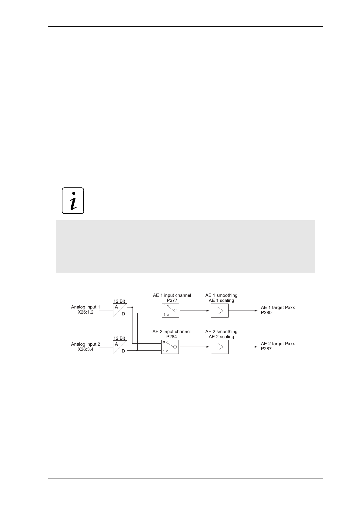
Parameter
7.13 Analog Inputs
Function
The function module in combination with the 2 analog inputs enable the programming of 2 byte length
parameters. Cycle time of analog inputs: 1 ms
Six parameters are assigned to each input:
– AI input channel: input channel entry
– AI smoothing: smoothing time constant [ms].
– AI scaling: scaling factor entry
– AI offset: offset entry
– AI threshold value: sensitivity of inputs
– AI target Pxxx: target parameter number entry
– AI value: current output value
NOTE
The sequence of the parameter setting is irre levant. Switching is carried out as soon as the target
parameter number has been set.
The target parameter number must be reset to zero in order to deactivate an input. However , the
target parameter still contains the last output value. If AI target Pxxx is deactivated or newly set,
the parameter „AI x offset“ is additionally set to zero.
.
V-Controller (BUS 6 VC) 73
Baumüller Nürnberg Electronic GmbH & Co. KG 5.03047.01
Page 76
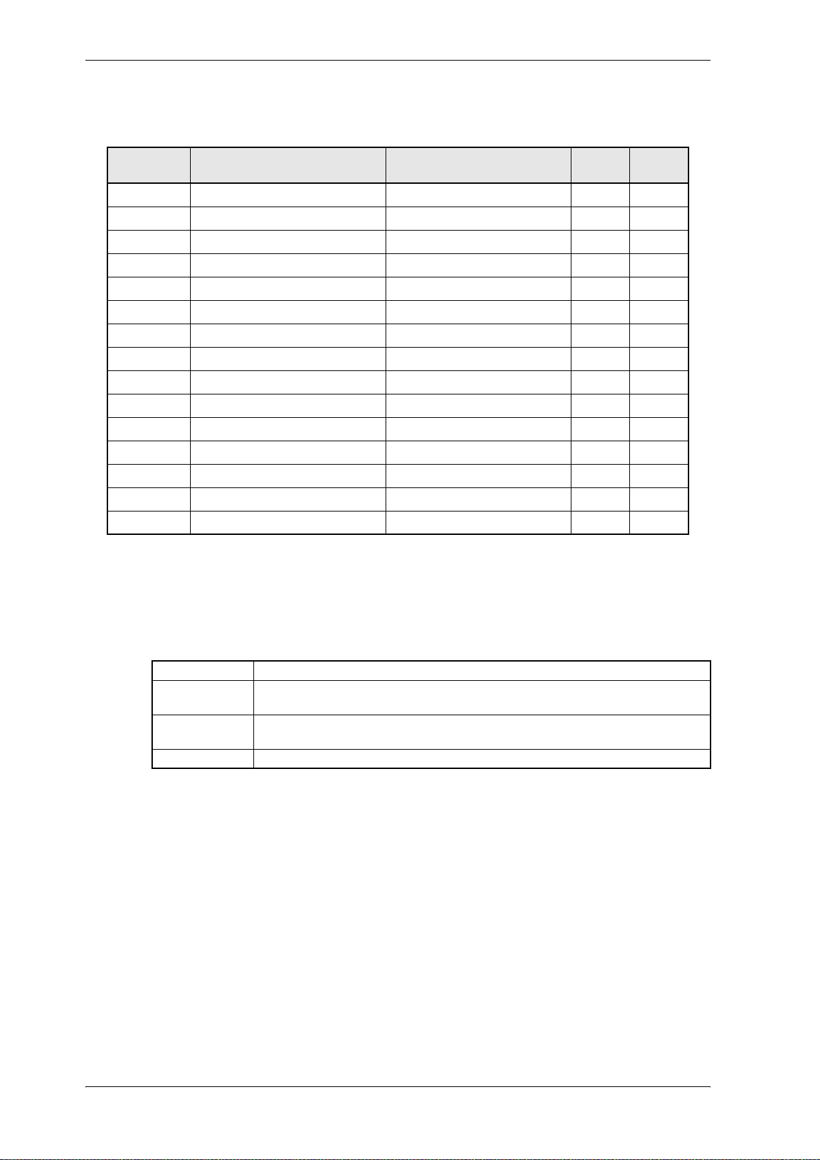
Parameter
Parameter overview
Parameter Name Range
min. ... max.
P302 AI state 0000 ... FFFF
P277 AI 1 input channel 0 ... 1
P278 AI 1 smoothing 1 ... 30 ms
P279 AI 1 scaling -2,00 ... 2,00
P280 AI 1 target Pxxx 0 ... 700
P281 AI 1 offset -100,00 ... +100,00 %
P282 AI 1 threshold value 0,00 ... 100,00 %
P283 AI 1 value -100,00 ... +100,00 %
P284 AI 2 input channel 0 ... 1
P285 AI 2 smoothing 1 ... 30 ms
P286 AI 2 scaling -2,00 ... 2,00
P287 AI 2 target Pxxx 0 ... 700
P288 AI 2 offset -100,00 ... +100,00 %
P289 AI 2 threshold value 0,00 ... 100,00 %
P290 AI 2 value -100,00 ... +100,00 %
Unit Display
only
!
!
!
Parameter description
P302 AI state
This parameter indicates the status of the analog inputs module.
Bit No. Meaning
0 0: Evaluation of analog input 1 disabled
1 0: Evaluation of analog input 2 disabled
2 ... 15 reserved
P277 AI 1 input channel
P284 AI 2 input channel
Entry of the analog input for respective channel.
The two hardware implemented analog inputs 1 and 2 can be connected with each input
channels. It is further possible to connect an analog input with different input channels.
P278 AI 1 smoothing
P285 AI 2 smoothing
In order to smooth interference on the analog input signal a smoothing time constant can be
entered in ms. Smoothing is switched off if the respective parameter is set to its minimum
value.
1: Evaluation of analog input 1 enabled
1: Evaluation of analog input 2 enabled
74 V-Controller (BUS 6 VC)
5.03047.01 Baumüller Nürnberg Electronic GmbH & Co. KG
Page 77
P279 AI 1 scaling
P286 AI 2 scaling
These parameters enable scaling of the analog input variable.
The output values (see parameters P283, P290, P297, P304) of unsigned parameters are 0
till +100 % and of signed parameters are -100 % till +100 %. Which analog input voltage this
maximum values achieved depends on the scaling factor.
P280 AI 1 target Pxxx
P287 AI 2 target Pxxx
The receiver address for the output value can be set via this parameter.
Parameter
NOTE
No target parameter number check is carried out.
P281 AI 1 offset
P288 AI 2 offset
These parameters can compensate for a possibly existing input voltage offset.
P282 AI 1 threshold value
P289 AI 2 threshold value
The sensitivity of the inputs can be set via the threshold values.
P283 AI 1 value
P290 AI 2 value
The AI value displays the respective current output value taking scaling and offset compensation into consideration.
V-Controller (BUS 6 VC) 75
Baumüller Nürnberg Electronic GmbH & Co. KG 5.03047.01
Page 78

Parameter
Basics of equation:
Maximum target parameter value: MAX_value
Analog input voltage: U
Equation:
! Unsigned parameters:
V[] 10V+
U
in
AI_value %[]
----------------------------------
2U
inmax
V[]⋅
*Scaling*100%+Offset=
if AI_value > 100 % → AI_value = 100 %
! Signed parameters:
V[]
U
in
AI_value %[]
------------------------- -
U
inmax
V[]
*Scaling*100%+Offset=
if AI_value > 100 % → AI_value = 100 %
if AI_value < -100 % → AI_value = -100 %
Both for signed and unsigned parameters
|AI_value [%]| < threshold value [%] then AI_value = 0 %
{ -10 ... +10 V };
in
U
= +10V;
inmax
Written to the target parameter:
AI_value[%]
Value t etarg
--------------------------------
100%
MAXvalue⋅=
76 V-Controller (BUS 6 VC)
5.03047.01 Baumüller Nürnberg Electronic GmbH & Co. KG
Page 79
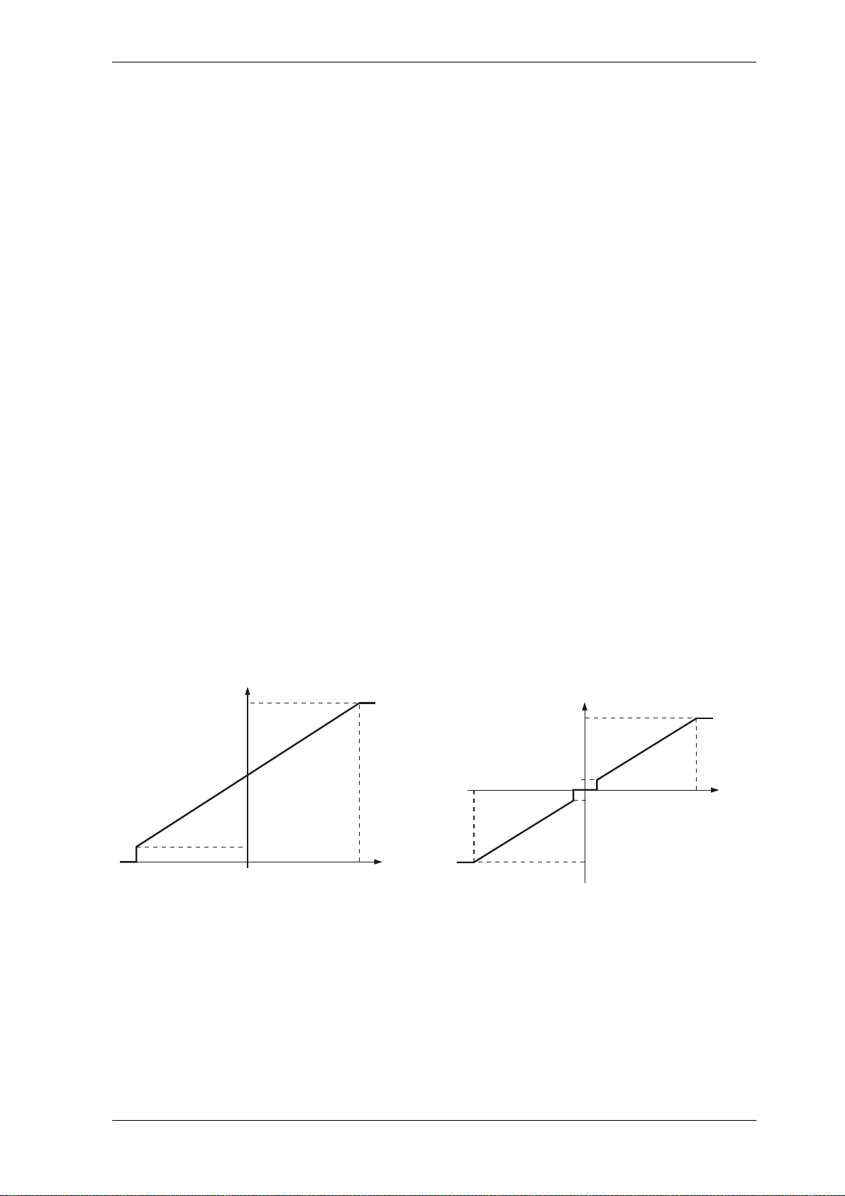
Examples:
S
]
Input voltage ↔ AI-value [%] * MAX_value
→ target parameter value
scaling = 1; offset = 0%; threshold value = 0%;
Unsigned target parameter:
10 V ↔ 100 % * MAX_value
5 V ↔ 75 % * MAX_value
0 V ↔ 50 % * MAX_value
- 5 V ↔ 25 % * MAX_value
- 10 V ↔ 0 % * MAX_value
scaling = 2; offset = -100%; threshold value = 0%;
Unsigned target parameter:
10 V ( 100 % * MAX_value
5 V ( 50 % * MAX_value
0 V ( 0 % * MAX_value
- 5 V ( 0 % * MAX_value (limitation !)
- 10 V ( 0 % * MAX_value (limitation !)
scaling = 1; offset = 0; threshold value = 10.1%;
Unsigned target parameter:
10 V ( 100 % * MAX_value
5 V ( 75 % * MAX_value
0 V ( 50 % * MAX_value
-5 V ( 25 % * MAX_value
- 9 V ( 0 % * MAX_value (threshold !)
- 10 V ( 0 % * MAX_value
Signed target parameter:
10 V ↔ 100 % * MAX_value
5 V ↔ 50 % * MAX_value
0 V ↔ 0 % * MAX_value
- 5 V ↔ -50 % * MAX_value
- 10 V ↔ -100 % * MAX_value
Signed target parameter:
10 V ( 100 % * MAX_value
5 V ( 0 % * MAX_value
0 V ( -100 % * MAX_value
- 5 V ( -100 % * MAX_value (limitation !)
- 10 V ( -100 % * MAX_value (limitation !)
Signed target parameter:
10 V ( 100 % * MAX_value
5 V ( 50 % * MAX_value
1 V ( 0 % * MAX_value (threshold !)
- 1 V ( 0 % * MAX_value (threshold !)
- 5 V ( -50 % * MAX_value
- 10 V ( -100 % * MAX_value
Parameter
Examples of characteristic curves:
Unsigned target parameter
Offset = 0 %; scaling = 1 Offset = 0 %; scaling = 1
AI_value [%]
100
50
-10
Threshold
0+10
U [V]
in
igned target parameter
-10
Threshold
AI_value [%]
+100
Threshold
-100
+10
U [V
in
V-Controller (BUS 6 VC) 77
Baumüller Nürnberg Electronic GmbH & Co. KG 5.03047.01
Page 80
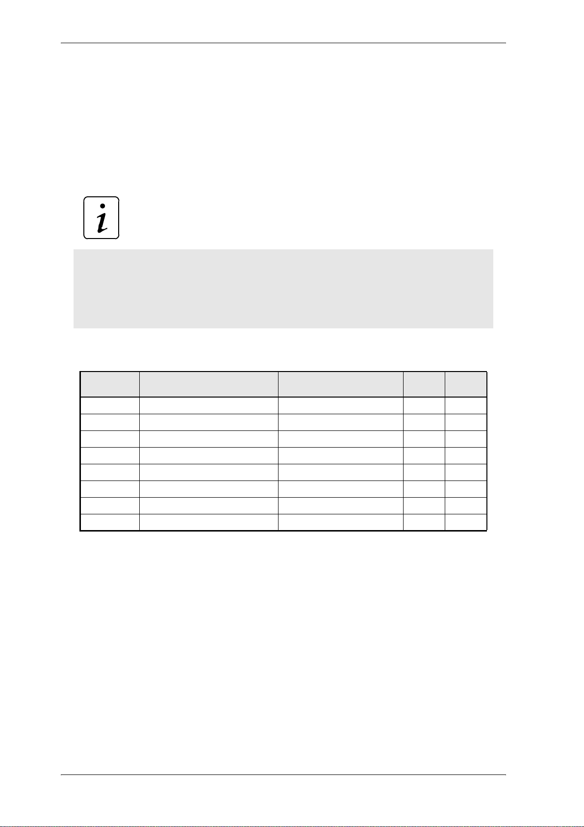
Parameter
7.14 Analog Outputs
Function
The module „analog outputs“ transmits freely selectable (and scalable) parameter values to an analog
output via a 12-bit digital-to-analog converter. It is possible transmitting 32-bit parameter either the low
word to one channel or to channel 1 the low word and to channe l 2 the high word of the 32 bit parameter.
At a voltage range of ± 10 V the output current should not exceed 1 mA.
NOTE
The following sequence must be observed for writing the parameters:
1.AA x source-Pxxx
2.AA x offset
3.AA x scaling
Parameter overview
Parameter Name Range
P338 AO state 0 ... FFFF -
P337 AO test value -10,000 ... +10,000 V
P330 AO 1 source Pxxx 0 ... 700
P331 AO 1 offset -100000 ... +100000 Dig
P332 AO 1 scaling -25000 ... +25000 Dig/V
P334 AO 2 source Pxxx 0 ... 700
P335 AO 2 offset -100000 ... +100000 Dig
P336 AO 2 scaling -25000 ... +25000 Dig/V
min. ... max.
Unit Display
only
!
78 V-Controller (BUS 6 VC)
5.03047.01 Baumüller Nürnberg Electronic GmbH & Co. KG
Page 81
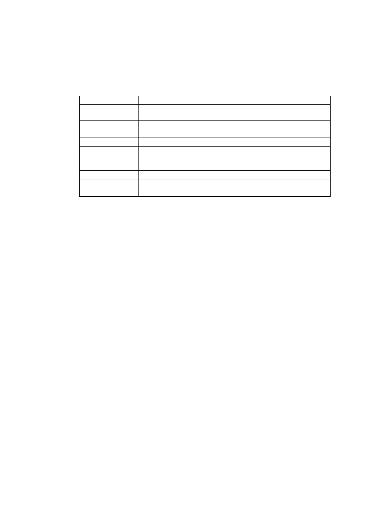
Parameter description
P338 AO state
Display of internal function module state.
Bit no. Meaning
0 0: STOP, analog output 1 switched off
1 ... 3 reserved
4 analog output 1 at negative threshold (-10V) (X26:7)
5 analog output 1 at positive threshold (+10V) (X26:7)
8 0: STOP, analog output 2 switched off
9...11 reserved
12 analog output 2 at negative threshold (-10V) (X26 :8)
13 analog output 2 at positive threshold (+10V) (X26:8)
14 ... 15 reserved
Parameter
1: RUN, analog output 1 is active
1: RUN, analog output 2 is active
P337 AO test value
The analog output (DA converter) can be tested via this parameter.
e.g. AO 1 source Pxxx P330 = 337
AO test value P337 = +10 → analog output 1 = + 10 V
AO 1 scaling P332 = -2000 → analog output 1 = - 5 V
AO offset channel 1 P331 = 14000 → analog output 1 = + 2 V
P330 AO 1 source Pxxx
P334 AO 2 source Pxxx
The output parameter numbers are entered here.
The respective channel is switched off, if this parameter is equal 0.
If a 32 bit parameter is programmed on one channel, the low word of this para meter is tran smitted. To transmit the high word, both channels (P330 and P334) must be programmed to
the same parameter. As a result channel 1 transmits the low word and channel 2 the high
word of the 32 bit parameter. Is channel 1 programme d to another p arameter the n channel 2
transmits the low word. That means that the high word of a parameter can´t be transmitted
separately without the low word. Channel 1 transmits always the low word and channel 2
transmits always the high word.
P331 AO 1 offset
P335 AO 2 offset
The offset of the analog outputs is set here.
P332 AO 1 scaling
P336 AO 2 scaling
A scaling factor can also be selected for optimum parameter output. The respective channel
is switched off, if this parameter is equal 0.
V-Controller (BUS 6 VC) 79
Baumüller Nürnberg Electronic GmbH & Co. KG 5.03047.01
Page 82
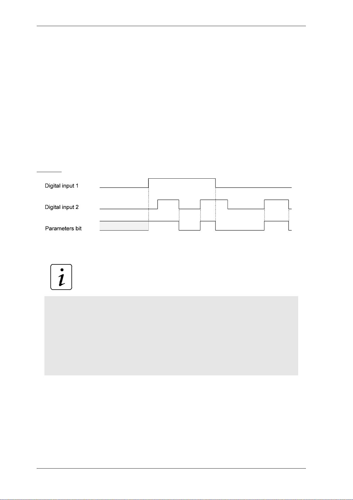
Parameter
7.15 Digital Inputs
The module and the four available digital inputs enable 16 bit parameter programming.
Four parameters are assigned to each input:
– DI x target Pxxx: Input of target parameter number
– DI x bit selection : Selection of the target parameter bits which are to be altered.
– DI x LOW pattern : Bit pattern which is written into the target parameter if switch is OFF.
– DI x HIGH pattern : Bit pattern which is written into the target parameter if switch is ON.
The inputs only evaluate the transitions
Hence it is possible to manipulate the same parameter via several inputs.
Example: Two inputs act on the same parameter bit
The 4 inputs are sampled every 4 ms at an interval of approx. 20 µs. In the event of simultaneous status
change of two signals the signal with the higher priority is taken over (digital input 1 has the lowest pri
ority, digital input 4 the highest).
NOTE
The activation of a digital input results in setting all parameters of the selected input.
Following order must be observed:
1.DO x target Pxxx
2.DO x bit selection
3.DO x LOW pattern
4.DO x HIGH pattern
In order to deactivate an input the DI target Pxxx must be set to 0.
Example of programming procedure:
1. Enter target parameter number in DI x target Pxxx of desired input.
⇒ Has no effect on the target parameter yet.
-
2. Enter DI x bit selection:
⇒ all bits which have not been selected are set to 0 in the LOW and HIGH patterns;
the selected bits are set to 0 in the target parameter and are replaced by the corresponding bit
pattern (according to switch position).
80 V-Controller (BUS 6 VC)
5.03047.01 Baumüller Nürnberg Electronic GmbH & Co. KG
Page 83
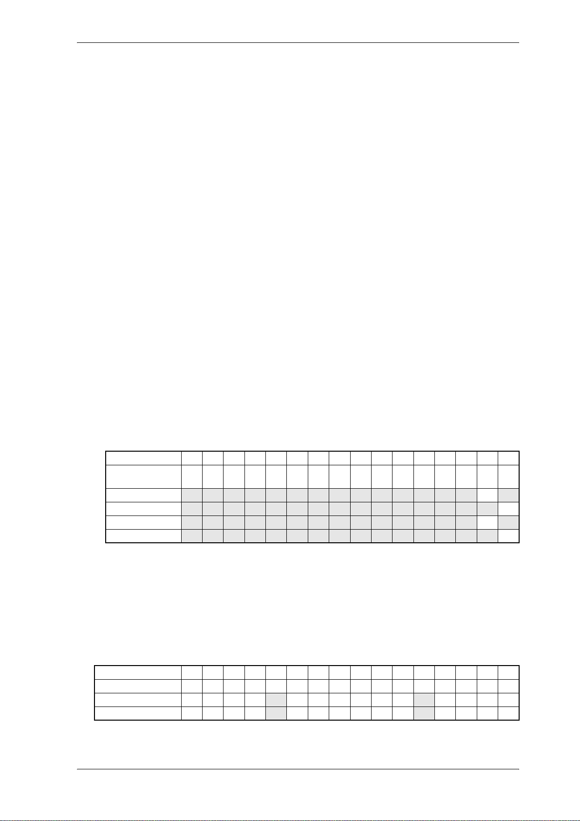
Parameter
3. Enter DI x LOW- and HIGH pattern of the above mentioned input.
⇒ Has no effect on the target parameter yet.
Examples:
1. Input 1 should set parameter P013 to 0 (switch is LOW) and to 1 (switch is HIGH).
Set
DI 1 target Pxxx (P370) to 13,
DI 1 bit selection (P371) to FFFF
DI 1 LOW pattern (P372) to 0000,
DI 1 HIGH pattern (P373) to 0001,
2. Through programming of a further input the values 2 and 3 should adjusted in parameter P013. Fol-
lowing sequence is necessary:
Set
DI 1 target Pxxx (P370) to 13,
DI 1 bit selection (P371) to FFFD
DI 1 LOW pattern (P372) to 0000,
DI 1 HIGH pattern (P373) to 0001,
DI 2 target Pxxx (P374) to 13,
DI 2 bit selection (P375) to FFFE,
DI 2 LOW pattern (P376) to 0000,
DI 2 HIGH pattern (P377) to 0002.
→ The digital input 1 effects bit no. 0 and. 2 till 15; the digital input 2 effects bit no. 1 till 15.
Bit no. 15 14 13 12 11 10 9 8 7 6 5 4 3 2 1 0
Example for start
value P013
input 1 → HIGH 0 0 0 0 0 0 0 0 0 0 0 0 0 0 0 1
input 2 → HIGH 0 0 0 0 0 0 0 0 0 0 0 0 0 0 1 1
input 1 → LOW 0 0 0 0 0 0 0 0 0 0 0 0 0 0 1 0
input 2 → LOW 0 0 0 0 0 0 0 0 0 0 0 0 0 0 0 0
1 1 1 1 0 0 0 0 1 1 1 1 0 1 0 1
3. The digital input 3 should effect bit no. 4 and 11 of parameter P120.
Set
DI 3 target Pxxx (P378) to 120,
DI 3 bit selection (P379) to 0810,
DI 3 LOW pattern (P380) to 0800,
DI 3 HIGH pattern (P381) to 0010,
Bit no. 15 14 13 12 11 10 9 8 7 6 5 4 3 2 1 0
Start value P120 0 0 0 0 0 0 0 0 0 0 0 0 1 1 1 1
input 2 → HIGH 0 0 0 0 0 0 0 0 0 0 0 1 1 1 1 1
input 2 → LOW 0 0 0 0 1 0 0 0 0 0 0 0 1 1 1 1
V-Controller (BUS 6 VC) 81
Baumüller Nürnberg Electronic GmbH & Co. KG 5.03047.01
Page 84
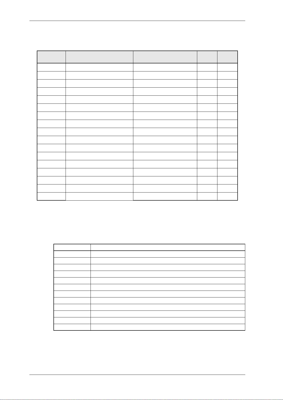
Parameter
Parameter overview
parameter Name Range
min. ... max.
P382 DI state 0000 ... FFFF
P370 DI 1 target Pxxx 0 ... 700
P371 DI 1 bit selection 0000 ... FFFF
P372 DI 1 LOW pattern 0000 ... FFFF
P373 DI 1 HIGH pattern 0000 ... FFFF
P374 DI 2 target Pxxx 0 ... 700
P375 DI 2 bit selection 0000 ... FFFF
P376 DI 2 LOW pattern 0000 ... FFFF
P377 DI 2 HIGH pattern 0000 ... FFFF
P378 DI 3 target Pxxx 0 ... 700
P379 DI 3 bit selection 0000 ... FFFF
P380 DI 3 LOW pattern 0000 ... FFFF
P381 DI 3 HIGH pattern 0000 ... FFFF
P342 DI 4 target Pxxx 0 ... 700
P343 DI 4 bit selection 0000 ... FFFF
P344 DI 4 LOW pattern 0000 ... FFFF
P345 DI 4 HIGH pattern 0000 ... FFFF
Unit Display
only
!
Parameter description
P382 DI state
This parameter indicates the state of input programming.
Bit no. Meaning
0 1: input 1 completely programmed
1 1: input 2 completely programmed
2 1: input 3 completely programmed
3 1: input 4 completely programmed
4 ... 7 reserved
8 actual state input 1 (X26:15)
9 actual state input 2 (X26:16)
10 actual state input 3 (X26:17)
11 actual state input 4 (X26:18)
12 ... 13 reserved
14 actual state rapid halt input (X26:19)
15 actual state pulse / controller enabling (X26:14)
82 V-Controller (BUS 6 VC)
5.03047.01 Baumüller Nürnberg Electronic GmbH & Co. KG
Page 85

P370 DI 1 target Pxxx
P374 DI 2 target Pxxx
P378 DI 3 target Pxxx
P342 DI 4 target Pxxx
This parameter indicates the parameter number of the target parameter for input 1 till 4.
P371 DI 1 bit selection
P375 DI 2 bit selection
P379 DI 3 bit selection
P343 DI 4 bit selection
The bits to be altered are selected in the target parameter.
P372 DI 1 LOW pattern
P376 DI 2 LOW pattern
Parameter
P380 DI 3 LOW pattern
P344 DI 4 LOW pattern
Bit pattern which is written into the selected target parameter bits when digital input is LOW.
P373 DI 1 HIGH pattern
P377 DI 2 HIGH pattern
P381 DI 3 HIGH pattern
P345 DI 4 HIGH pattern
Bit pattern which is written into the selected target parameter bits when digital input is HIGH.
V-Controller (BUS 6 VC) 83
Baumüller Nürnberg Electronic GmbH & Co. KG 5.03047.01
Page 86
Parameter
7.16 Digital Outputs
Function
The module enables programming of the three a vailable digital outputs. Three par ameters are a ssigned
to each output:
– DI output ID no.: Input of source parameter number
(only 2-byte parameters admissible)
– DI bit selection: Selection of source parameter bits to which bit pattern must
correspond.
– DI bit pattern If this bit pattern and the selected parameter bit pattern correspond to
each other, the output is switched to HIGH.
NOTE
The following sequence must be observed for writing the parameters:
1.DA x source-Pxxx
2.DA x bit selection
3.DA x bit pattern
Note:
The sequence of the parameter setting is irrelevant. Switching takes place only after all three para meters
have been set.
In order to deactivate an output either DI source Pxxx or DI bit selection must be set to 0. The last switch
state, however, remains stored in the o utpu t. Th e output can be programmed again by setting the rele
vant parameter again.
Example of programming procedure:
1.Enter source parameter number in DO x source Pxxx of your choice.
-
→ Has no effect on the output yet.
2.Enter DO x bit pattern of the above mentioned parameter.
→ Has no effect on the output yet.
3.Enter bit selection:
→ All bits which have not been selected are set to 0 in the DO bit pattern, the bits selected from
the source parameter are compared to the DO bit pattern.
If one of the two patterns co rresponds to the source parameter pattern, the output is set to
HIGH.
84 V-Controller (BUS 6 VC)
5.03047.01 Baumüller Nürnberg Electronic GmbH & Co. KG
Page 87
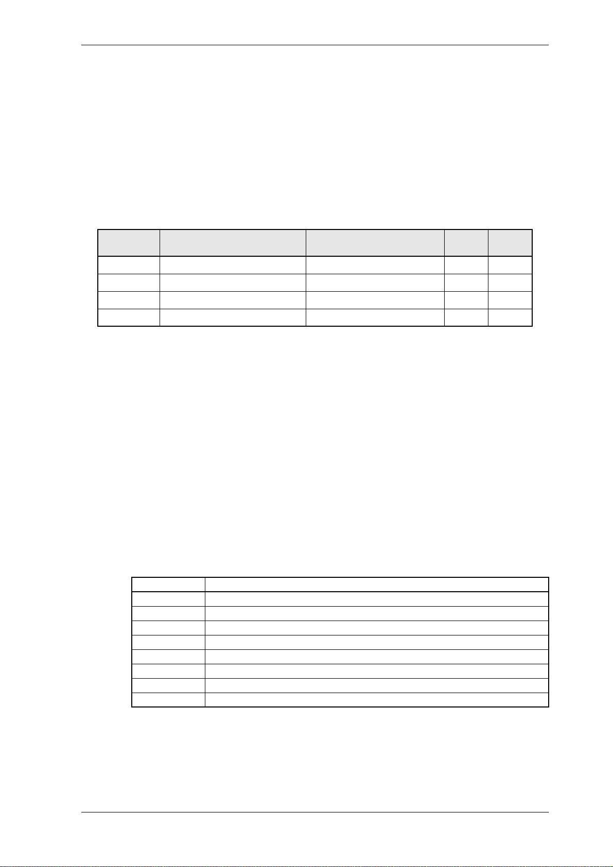
Example:
1.First set DO 1 source Pxxx to 13,
DO 1 bit pattern to 0001,
and DO 1 bit selection to 0003.
→ if bit no. 1 and bit no. 2 of parameter P013 result in „1“, the output 1 is switched to high.
Parameter overview
Parameter
Parameter Name Range
P383 DO 1 source Pxxx 0 ... 700
P384 DO 1 bit selection 0000 ... FFFF
P385 DO 1 bit pattern 0000 ... FFFF
P392 DO state 0000 ... FFFF
Parameter description
P383 DO 1 source Pxxx
This parameter indicates the parameter number of the source parameter for ou tputs 1, 2 or 3.
P384 DO 1 bit selection
The bits to be compared are selected in the source parameter.
P385 DO 1 bit pattern
Bit pattern which is compared to the source parameter bit pattern.
min. ... max.
Unit Display
only
!
P392 DO state
This parameter shows the state of the function module.
Bit no. Meaning
0 1: output 1completely programmed
1 1: output 2 completely programmed
2 1: output 3 completely programmed
3 ... 7 reserved
8 actual state output 1 (X26:21)
9 actual state output 2 (X26:22)
10 actual state output 3 (X26:23)
11 ... 15 reserved
V-Controller (BUS 6 VC) 85
Baumüller Nürnberg Electronic GmbH & Co. KG 5.03047.01
Page 88
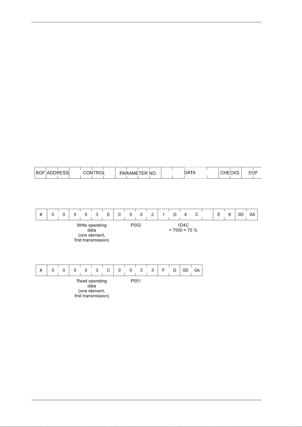
Parameter
7.17 Service Interface
Function
The service interface allows communication with the PC operating program. The BASS protocol is operated via the RS 232 interface X23.
The address of each drive is set in binary code at the controller front via DIP switch. Bit no. 0 thus cor-
responds to switch 1, bit no. 1 to switch 2 etc.
The RS 232 interface is constructed potential-free, the operating mode is full-duplex.
Data format: 8 data bits, 1 stop bit, no parity
Transmission speed: 9600 baud
Transmission format: ASCII
Communication PC ⇒ drive
Example 1: Set P002 to 75 %
Example 2: Read P051
86 V-Controller (BUS 6 VC)
5.03047.01 Baumüller Nürnberg Electronic GmbH & Co. KG
Page 89
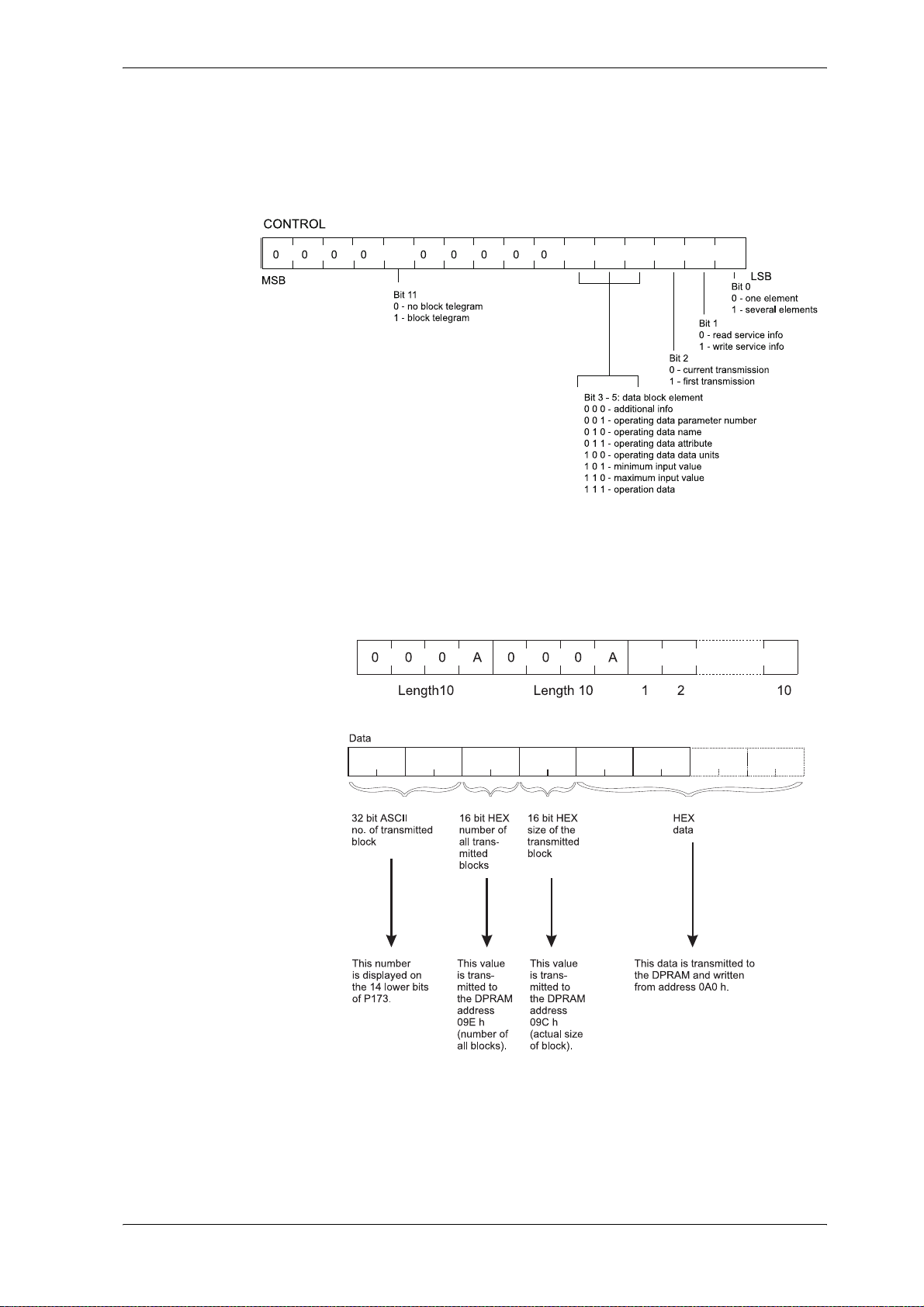
Parameter
BOF # (23
Address of the drive 0
dec
)
hex
to 255
dec
(00
hex
to FF
hex
)
Control
Parameter number Hexadecimal value of the parameter number as an ASCII character
Data Element, error type
– Number are given as hexadecimal number s and are transmitted as ASCII char-
acters
– The half-byte with the highest value is transmitted first
– Really text begins with two words following one after another which contains the
length of the text:
Checksum Sum of the hexadecimal values of all ASCII characters without BOF and EOF. Any over-
flow is also added (234
EOF <CR> <LF> (0D
hex
, 0A
hex
hex
→36
)
hex
)
V-Controller (BUS 6 VC) 87
Baumüller Nürnberg Electronic GmbH & Co. KG 5.03047.01
Page 90
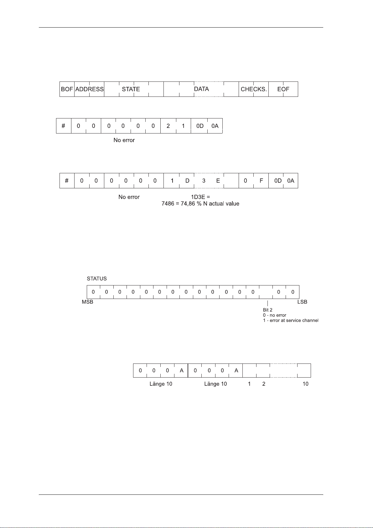
Parameter
Communication drive ⇒ PC
Before the drive answered the echo telegram is sended from drive to PC!
Example 1: Set P002 to 75 %
Example 2: Read P051
BOF # (23
Address of the drive 0
State
Parameter number Hexadecimal value of the parameter number as an ASCII character
Data Element, data state, error type
Checksum Sum of the hexadecimal values of all ASCII characters without BOF and EOF. Any over-
EOF <CR> <LF> (0D
)
hex
to 255
dec
Really text begins with two words following one after another which contains the length of
the text:
flow is also added (234
dec
(00
hex
hex
, 0A
to FF
hex
hex
hex
→36
)
)
hex
)
88 V-Controller (BUS 6 VC)
5.03047.01 Baumüller Nürnberg Electronic GmbH & Co. KG
Page 91
Error table
Parameter overview
Parameter
Error number Meaning
0 No fault
1 Element is not available
2 Datum is too short
3 Datum is too long
4 Datum is not alterable
5 Parameter is write protected
6 Datum is smaller than minimum value
7 Datum is greater than maximum value
8 Datum is invalid
9 Obtaining of parameter is invalid
Parameter Name Range
P170 SI state 0000 ... FFFF
P171 SI baud rate 50 ... 19200 Baud
P172 SI mode 0000 ... 0003
Parameter description
P170 SI state
Write-access to the drive parameters is managed via parameter M communication source
(P126) in the drive manager. The drive parameter can only be a ltered via the service interface
when bit no. 0 of this parameter is set to 1. If the bit is set to 0 write-access is inhibited and
only read-access to the parameter values granted.
See also M communication source (P126)
Bit no. Meaning
0 ... 3 status of function module
0001: RUN (all parameters can be read and write)
0000: STOP (all parameters can be read only)
11 ... 15 reserved
min. ... max.
Unit Display
only
!
!
P171 SI baud rate
The service baud rate can only be displayed and is set to a fixed value of 9600 baud.
V-Controller (BUS 6 VC) 89
Baumüller Nürnberg Electronic GmbH & Co. KG 5.03047.01
Page 92

Parameter
90 V-Controller (BUS 6 VC)
5.03047.01 Baumüller Nürnberg Electronic GmbH & Co. KG
Page 93

Maintenance
8 MAINTENANCE
WARNING
The equipment carries a dangerously high voltage and has dangerous rotating parts (fans). Ignoring
the safety and warning information may result in death, severe pe rsonal injury or damage to p roperty.
You may only carry out maintenance when the unit is deenergized.
Do not begin work on the power stage and the intermediate circuit until you have made sure that the
unit is not carrying potential or a voltage (remanent charge).
When dismounting safety devices during commissioning, re pair and maintenance wor k, you must ensure that the machine is taken out of commission exactly as specified. You must remount and check
safety equipment immediately after completing commissioning, repair and maintenance work.
After carrying out any work involving intervention in the machine – regardless of whether this involves
the motor, the actual value acquisition or the power converter – the owner must carry ou t acceptance
testing and document it chronologically in the machine log. Failure to do this may result in the owner
being faced with consequences relating to liability legislation.
8.1 Maintenance Information
The units supplied are maintenance-free.
Prohibition of unauthorized modifications
For safety reasons, unauthorized additions or modifications to the drive are not allowed.
V-Controller (BUS 6 VC) 91
Baumüller Nürnberg Electronic GmbH & Co. KG 5.03047.01
Page 94

Maintenance
8.2 Error Messages
In the event of an error, parameter M error code (P124) indicates the appropriate error code. This error
is acknowledged when bit Reset disturbance in M control word (P120) is set from 0 to 1. If there is more
than one error, the system shows the next one immediately after acknowledgement.
! Drive Manager Function Module (Error ID 00xx)
Error ID Error Text Meaning Error reaction Remedy
0001
0003
0004
0005
0010
BASS protocol timeout The communications source set in
hex
Dual-Port RAM time-
hex
out (cyclical data)
Dual-Port RAM time-
hex
out (working data)
System boot procedure An error was determined while
hex
Error switch (program
hex
error)
P124 has not responded for longer
than the timeout set in P128.
reading the boot data set from the
EEPROM. You can get more infor
mation about the type of error by
referring to parameter DSM Mes
sage (P192).
This disturbance usually occurs if
you replaced the controller firm
ware with firmware that is incompatible.
Only for software development Inhibit pulses imme-
Error reaction can be
set in P189
Inhibit pulses immediately
-
-
-
diately
Check communications
(cables, daughterboard,
etc.)
You should carefully
check the data set in the
controller’s RAM and then
program it in the EE
PROM as the boot data
set.
-
92 V-Controller (BUS 6 VC)
5.03047.01 Baumüller Nürnberg Electronic GmbH & Co. KG
Page 95

! Power Unit Function Module (Error ID 02xx)
see also Function Module Processor Error Recognition (Error ID 0Cxx) on page 95
Maintenance
Fehler-
kennung
0201
hex
0202
hex
0203
hex
0204
hex
0205
hex
0207
hex
0208
hex
0209
hex
020A
hex
020B
hex
020C
hex
020D
hex
020E
hex
020F
hex
0210
hex
0D01
hex
Fehlertext Bedeutung Fehlerreaktion Störungsbeseitigung
Overvoltage Uzk The bus voltage, UZK, has ex-
ceeded a value of 800 V ± 1%
Inhibit pulses immediately
Check the ballast resistor.
If no ballast resistor is
available check Uzk con
troller setting
Overcurrent At least one of the power unit’s
three phase currents has overwrit
ten the value of 1,3 x I
max
(= 1,3 x
Inhibit pulses im-
-
mediately
Check the current controller’s setting
P113)
Error current An error current was determined in
the power unit that exceeded a
specific amount. (For more de
tailed information, refer to the
-
Inhibit pulses immediately
Check the mains connection and the intermediate
circuit connection for a
ground fault
power unit description.)
Disturbance in auxiliary
voltage supply
Overtemperature of
power unit
There is no power supply for transistor control in the power unit.
The temperature of the power unit
has risen above 85° C.
Inhibit pulses immediately
Inhibit pulses immediately
Check control of the safety
relay
The disturbance cannot be
acknowledged until the
power unit temperature
shown in P118 has fallen
below 85° C.
Transistor error (group
message)
Phase U top
Phase U bottom
Phase V top
Phase V bottom
Phase W top
Phase W bottom
Power unit ID unknown The control unit does not know the
UCE monitoring of one or more
power transistors has tripped due,
for example, to a short circuit or
ground fault or because of defects
in the transistor.
read identifier
Inhibit pulses immediately
Inhibit pulses immediately
Check the motor cables
for a short circuit or
ground fault.
Allow the power unit to
cool down.
If the disturbance keeps
occurring, replace the
power unit.
Read off the power unit
version from the rating
plate and compare it with
the list in P117. The error
cannot be acknowledged.
Wrong power unit type The stored power unit type does
not match the one the system
read, e.g. because no data set has
been stored yet or you plugged
the control unit into another power
Inhibit pulses immediately
Check the parameterization and, if necessary,
change it. Save the data
set and acknowledge the
error.
unit.
Disturbance in power
unit
The ready for use signal from the
power unit is missing even though
there are no other power unit dis
Inhibit pulses immediately
-
Refer to the power units
operating instructions.
turbance messages.
Short circuit temperature sensor
The power unit temperature is
below the temperature threshold
of -40°C. Normally, this distur
-
Inhibit pulses immediately
Temperature detection
defective, the disturbance
cannot be eliminated.
bance occurs if there is a short circuit in the temperature detection
during operation.
-
V-Controller (BUS 6 VC) 93
Baumüller Nürnberg Electronic GmbH & Co. KG 5.03047.01
Page 96
Maintenance
! Power Supply Function Module (Error ID 05xx)
Error ID Error Text Meaning Error reaction Remedy
0503
! Data Set Management Function Module (Error ID 09xx)
Error ID Error Text Meaning Error reaction Remedy
0901
0902
0903
Fault
hex
PLL
EEPROM copy error A data difference was determined at
hex
Missing boot data set There is no boot data set (DS no. 0)
hex
Checksum error in boot
hex
data set
Mains jitter has exceeded the
mains jitter limit
copying of the EEPROM during initial
ization of data set management
in the EEPROM
At checking of the boot data set, the
system calculated a different check
sum than the one that was expected,
i.e. a boot data set is present but it is
invalid due to data corruption.
Inhibit pulses immediately
Inhibit pulses immedi-
-
ately
Inhibit pulses immediately
Inhibit pulses immedi-
-
ately
Check mains voltage
X1:8/9/10 at BUC Gerät.
Reset error memory.
This error cannot
be acknowledged
and you can only
eliminate it by
switching the elec
tronics supply off
and on again. If the
error occurs repeat
edly, this indicates
that there is a de
fect in the controller hardware.
You must create
the boot data set in
RAM and then save
it to the EEPROM.
You must create
the boot data set in
RAM and then save
it to the EEPROM.
-
-
-
! Operating System Function Module (Error ID 0Bxx)
Error ID Error Text Meaning Error reaction Remedy
0B01
0B02
0B03
0B04
*) Errors cannot be acknowledged.
Main program comput-
hex
ing time exceeded
Task computing time
hex
exceeded
Sync. IR computing
hex
time exceeded
* DSP computing time
hex
exceeded
Inhibit pulses immediately
Inhibit pulses immediately
Inhibit pulses immediately
Inhibit pulses immediately
P160 selection = 0,
P169 value = 0,
Store the data set
again and acknowl
edge the error. If
necessary deacti
vate functions not
needed for instance
digital and analog
I/O´s by parameterization
-
-
94 V-Controller (BUS 6 VC)
5.03047.01 Baumüller Nürnberg Electronic GmbH & Co. KG
Page 97
Maintenance
! Function Module Processor Error Recognition (Error ID 0Cxx)
Error ID Error Text Meaning Error reaction Remedy
0B05
0B06
0C01
0C02
0C03
0C04
0C05
0C06
0C07
0C08
0C09
Error in linking the pro-
hex
gram modules
Error in the time seg-
hex
ment system configuration
illegal external bus
hex
access
illegal instruction
hex
access
illegal word operand
hex
access
protection fault
hex
undefined opcode
hex
stack underflow
hex
stack overflow
hex
external non maskable
hex
interrupt
watchdog time-out
hex
Further information see
memory
0xFA00 up to
0xFA0F.
Inhibit pulses immediately
Test the RAM
re-boot controller
! Function Module Power Unit continued (Error ID 0Dxx)
Error
identifi
cation
0D01
-
hex
Error text Meaning Error response Disturbance elimination
Short circuit of the temperature sensor (power
unit)
Inhibit pulses immediately
V-Controller (BUS 6 VC) 95
Baumüller Nürnberg Electronic GmbH & Co. KG 5.03047.01
Page 98

Maintenance
8.3 Disposal
For the most part, the equipment consists of the following components and materials:
Component Material
Various spacers, housing of current converter and unit fan,
etc.
PCBs on which all the open- and closed-loop electronics are
mounted
For technical reasons, electronic components might need to contain dangerous materia ls, so you should
not open them.
If the components are used correctly, there is no danger to human beings or to the environment.
Plastic
Base material: Epoxy-resin fiberglass woven
material, copper-coated on both sides and
plated-through, various electronic components
such as condensors, resistors, relays, semi
conductors, etc.
-
In case of fire, dangerous compounds may result or hazardous materials may be released.
You must dispose of or recycle equipment or components according to national regulations as well as
any applicable local or regional ordinances.
96 V-Controller (BUS 6 VC)
5.03047.01 Baumüller Nürnberg Electronic GmbH & Co. KG
Page 99
9 APPENDIX
9.1 Declaration by Manufacturer
EG-Herstellererklärung
Declaration by Manufacturer
gemäß EG-Richtlinie 98/37/EG (Maschinen) vom 22.06.1998
geändert durch: 98/79/EG vom 27.10.1998
in accordance with EC directive 98/37/EG (machinery) dated 22.06.1998
changed by: 98/79/EC dated 27.10.1998
BUS 6 VC - 00 - 0100 - .... - .... - ....
Appendix
Die Inbetriebnahme der Maschine, in die dieses Gerät eingebaut wird, ist untersagt bis die Konformität
der Maschine mit der obengenannten Richtlinie erklärt ist.
The machinery into which this unit is to be incorporated must not be put into service until the machinery
has been declared in conformity with the provisions of the directive mentioned above.
Bei der Entwicklung und Konstruktion des Geräts wurden folgende Normen beachtet:
The development and construction of the unit is complied with following standards:
Norm / standard
EN 60204-1 Sicherheit von Maschinen - Elektrische Ausrüstung von Maschinen
Safety of machinery - Electrical equipment of machines
Baumüller Nürnberg Electronic GmbH & Co. KG, Ostendstr. 80 - 90, D- 90482 Nürnberg
Nürnberg, 02.02.2004
_________________________ _________________________
Dr. Peter Kreisfeld Dr. Heidrich
Geschäftsführer Entwicklungsleiter
Head Division Head of development Seite 1 von 1 / page 1 of 1
V-Controller (BUS 6 VC) 97
Baumüller Nürnberg Electronic GmbH & Co. KG 5.03047.01
Page 100

Appendix
9.2 General Conditions of Sale and Delivery
1. Obligation and Conclusion of Contract
a) Deliveries of goods and provision of services shall be
effected exclusively based on these trading conditions.
They are an essential component of the contracts for
delivery and shall be considered as having been accepted
by the placing of an order. In the case of constant busi
ness relations, they also apply for the future contracts.
b) Agreements diverging from the contract and verbal collat-
eral agreements shall only be binding if they have been
confirmed in writing by Baumüller Nürnberg GmbH(herein
after referred to as Baumüller). Diverging trading conditions on the behalf of the purchaser shall be without
obligation, even where these have not been expressly
objected to. These General Conditions of Sale and Deliv
ery shall be considered as having been accepted by the
purchaser at the latest when the delivery is accepted.
c) In as far as deliveries of goods are subject to separate
external obligations in accordance with the Law Concern
ing Foreign Trade and Payments with respect to the Federal Office for Economics, the purchaser has to observe
the relevant conditions at his/her own responsibility.
2. Price and Offers
Offers are subject to confirmation, not binding and apply
subject to material supply possibilities. Supplements and
amendments require written confirmation. Prices are ex
works and are subject to confirmation. Invoicing takes
place in accordance with the prices valid on the date of
delivery.
3. Extent of Delivery and Delivery Time
a) Specified delivery periods/dates are without obligation, in
as far as nothing else to the contrary has been expressly
agreed upon in writing. Delivery periods do not commence
until the purchaser has fulfilled all duties of co-operation,
in particular regarding details of performance. In the event
that the agreed deposits for orders are delayed, then the
delivery time shall be extended accordingly.
b) The purchaser is entitled, in particular in the event of a
delay in delivery of longer than 3 months, to set an appro
priate period of grace and after its expiry, to withdraw from
the order. Claims to compensation due to non-fulfilment or
delay shall be excluded, in as far as Baumüller is not
responsible for intent or gross negligence.
c) Baumüller is entitled at any time to effect partial deliveries
and partial services, as well as to invoice these accord
ingly.
4. Delivery Problems
a) Delays/preventions in the delivery of goods or the provi-
sion of services due to force majeure entitle Baumüller to
delay the production and delivery by the duration of the
obstruction plus an appropriate period of time or to with
draw in part or in whole from the order.
b) Industrial disputes or other circumstances which substan-
tially impede or render impossible the delivery, such as, in
particular, disturbances in the operating processes, prob
lems in procuring materials, official directives also apply
as force majeure, irrespective of whether they arise with
regard to Baumüller or suppliers.
c) In these cases, Items 4 a), b), the purchaser shall have no
claim to compensation due to non-fulfilment or delay of
the delivery.
5. Packaging
Items for sale and delivery items are packaged and transport insurance policies are taken out according to the
instructions of and at a cost to the purchaser. Upon
demand, the packaging material has to be returned with
out delay, free of freight charges and expenses.
6. Dispatch and Passing of Risk
Deliveries shall be made ex works. The dispatch shall be
-
effected at a cost to and at the risk of the recipient of the
service/the purchaser. The risk passes to the recipient of
the delivery/purchaser as soon as the delivery items leave
the works. This shall apply at the latest, from the transfer
-
ral of the delivery items to the person carrying out the
transport, forwarding agent or carrier.
7. Warranty
a) The period of warranty amounts to 12 months from the
day of dispatch.
In the event that a delivery item is defective, Baumüller
shall deliver an additional replacement or make a subse
quent improvement at its own choice. Multiple subsequent
improvements are permissible. Other warranty claims on
the behalf of the purchaser, in particular also due to direct
or indirect consequential damage are excluded. The precondition for any warranty is the normal contractual use of
the delivery items. In the event of the utilisation of war
ranty services, the motor, the replacement part or the
device has to be sent in free of freight charges, packaging
costs or customs duties after prior co-ordination with
Baumüller. Baumüller is exempted from any warranty if
the party ordering returns the goods complained about
without prior co-ordination or contrary to agreement. War
ranty claims expire one month after rejection of a defect
on which notice is given, in as far as the purchaser
remains silent in this respect.
8. Notification of Defects
a) The purchaser shall examine the subject matter of the
contract and delivery items immediately and give notice of
any defects without delay, however, no later than 7 days
after receipt of the delivery. In case of non-obvious
defects notice has to be given in writing without delay after
-
their discovery, however, no later than 6 months from the
point of delivery. In the event that the purchaser does not
give notice of any defects in writing within this period of
time, then the subject matter of the contract shall be con
sidered as having been approved.
b) The purchaser shall allow Baumüller a suitable inspection
-
of defects of which notice is given and shall place all nec
essary/requested technical information, in particular,
inspection records and test reports at Baumüller's dis
posal. In the event that the purchaser fails to do so, then
the delivery items shall be considered as not having been
complained about and as being approved. In the event
that the purchaser alters the delivery items, then he/she
shall lose his/her warranty claims.
c) In the event of an established material defect or perfor-
mance defect, Baumüller can eliminate the defect or sup-
-
ply a replacement. The purchaser can demand rescission
or a reduction after the expiry of an appropriately set
period of grace. Further claims on the behalf of the pur
chaser, in particular to the reimbursement of dismantling
costs or installation costs are excluded. The same applies
to damages which do not affect the delivery item itself.
d) Natural wear and tear and damage which arises after the
transferral of risk, in particular also due to incorrect or neg
ligent handling, excessive demands or other unsuitable
use not in conformity with the contract are excluded from
-
-
-
-
-
-
-
-
-
-
98 V-Controller (BUS 6 VC)
5.03047.01 Baumüller Nürnberg Electronic GmbH & Co. KG
 Loading...