

Page 1
Manual
Language English
Translation
Document No. 5.07003.06
Part No. 410406
Status 13.10.2011
E
5.07003.06
b maXX® BM1000
Basic unit
Read the Operating Manual before starting any work!
Page 2

Copyright This Manual may be copied by the owner in any quantity, but only for internal use. This Man-
ual may not be copied or reproduced, in whole or in part, for any other purposes.
The use and disclosure of information contained in these Manual are not permitted.
Designations and company marks contained in these Manual could be trademarks, the use
of which by third parties for their own purposes could violate the rights of the rights holder.
Preliminary informationWarning Insofar as this document is identified as being preliminary information, the following
applies:
this version is regarded as providing advance technical information to users of the described
devices and their functions at an early enough time in order to adapt to any possible changes
or expanded functionality.
This information must be regarded as being preliminary, as it has not ye t passed through
Baumüller's internal review process. In particular, this information is still subject to changes,
thus no legal liability can be derived from this preliminary information. Baumüller assumes no
liability for damages that might arise from this possibly faulty or incomplete version.
If you detect or suspect any content errors and/or major form errors in this preliminary information, we request that you notify the Baumüller support specialist responsible for you.
Please provide us, via this employee, with your insights and comments so that we can take
them into account and include them when transitioning from the preliminary information to
the final information (as reviewed by Baumüller).
The conditions stipulated in the following section under "Obligatory" are invalid in case of preliminary information.
Obligatory These Manual are a part of the equipment/machine. These Manual must be available to the
operator at all times and must be in legible condition. If the equipment/machine is sold or
moved another location, these Manual must be passed on by the owner together with the
equipment/machine.
After any sale of the equipment/machine, this original and all copies must be handed over to
the buyer. After disposal or any other end use, this original and all copies must be destroyed.
When the present Manual are handed over, corre spon din g sets of operating in structions of
a previous version are automatically invalidated.
Please note that the specifications/data/information are current values according to the
printing date. These statements are not legally binding with regard to measurements,
computation or calculations.
Baumüller Nürnberg GmbH reserves the right, in devel oping its produ cts further, to change
the technical specifications and handling of it products concerned without prior notice.
No liability can be accepted concerning the correctness of these Manual unless otherwi se
specified in the General Conditions of Sale and Delivery.
© Baumüller Nürnberg GmbH
Ostendstr. 80 - 90
90482 Nuremberg
Germany
Tel. +49 9 11 54 32 - 0
Fax: +49 9 11 54 32 - 1 30
Email : [email protected]
Internet: www.baumueller.de
Page 3

Table of contents
1 Introduction . . . . . . . . . . . . . . . . . . . . . . . . . . . . . . . . . . . . . . . . . . . . . . . . . . . . . . . . . . . . . . 7
1.1 Survey of the appliance series b maXX® BM1000 . . . . . . . . . . . . . . . . . . . . . . . . . . . . 7
1.2 First steps . . . . . . . . . . . . . . . . . . . . . . . . . . . . . . . . . . . . . . . . . . . . . . . . . . . . . . . . . . . 7
1.3 Used terms . . . . . . . . . . . . . . . . . . . . . . . . . . . . . . . . . . . . . . . . . . . . . . . . . . . . . . . . . . 8
1.4 Copyright and trade mark . . . . . . . . . . . . . . . . . . . . . . . . . . . . . . . . . . . . . . . . . . . . . . . 8
2 Fundamental safety instructions . . . . . . . . . . . . . . . . . . . . . . . . . . . . . . . . . . . . . . . . . . . . . 9
2.1 General notes . . . . . . . . . . . . . . . . . . . . . . . . . . . . . . . . . . . . . . . . . . . . . . . . . . . . . . . . 9
2.2 Hazard information and commands. . . . . . . . . . . . . . . . . . . . . . . . . . . . . . . . . . . . . . . 10
2.2.1 Hazard information structure. . . . . . . . . . . . . . . . . . . . . . . . . . . . . . . . . . . . . . . . . . . 11
2.2.2 Form of the hazard sign (triangular or round) . . . . . . . . . . . . . . . . . . . . . . . . . . . . . . 11
2.2.2.1 Hazard information on personal injury. . . . . . . . . . . . . . . . . . . . . . . . . . . . . . . . . . . 12
2.2.2.2 Hazard information on property damage. . . . . . . . . . . . . . . . . . . . . . . . . . . . . . . . . 14
2.2.2.3 Command signs used . . . . . . . . . . . . . . . . . . . . . . . . . . . . . . . . . . . . . . . . . . . . . . . 14
2.3 Information sign . . . . . . . . . . . . . . . . . . . . . . . . . . . . . . . . . . . . . . . . . . . . . . . . . . . . . . 14
2.4 Legal instructions. . . . . . . . . . . . . . . . . . . . . . . . . . . . . . . . . . . . . . . . . . . . . . . . . . . . . 15
2.5 Appropriate use . . . . . . . . . . . . . . . . . . . . . . . . . . . . . . . . . . . . . . . . . . . . . . . . . . . . . . 15
2.6 Inappropriate use. . . . . . . . . . . . . . . . . . . . . . . . . . . . . . . . . . . . . . . . . . . . . . . . . . . . . 16
2.7 Safety equipment. . . . . . . . . . . . . . . . . . . . . . . . . . . . . . . . . . . . . . . . . . . . . . . . . . . . . 16
2.8 Training of the personnel. . . . . . . . . . . . . . . . . . . . . . . . . . . . . . . . . . . . . . . . . . . . . . . 17
2.9 Safety precautions in normal operation . . . . . . . . . . . . . . . . . . . . . . . . . . . . . . . . . . . . 17
2.10 Dangers due to residual energy. . . . . . . . . . . . . . . . . . . . . . . . . . . . . . . . . . . . . . . . . . 17
2.11 Disposal of the device . . . . . . . . . . . . . . . . . . . . . . . . . . . . . . . . . . . . . . . . . . . . . . . . . 18
2.12 Fire fighting . . . . . . . . . . . . . . . . . . . . . . . . . . . . . . . . . . . . . . . . . . . . . . . . . . . . . . . . . 18
2.13 Responsibility and liability . . . . . . . . . . . . . . . . . . . . . . . . . . . . . . . . . . . . . . . . . . . . . . 18
2.13.1 Observing the safety notes and safety instructions. . . . . . . . . . . . . . . . . . . . . . . . . . 18
2.13.2 Dangers when handling this device. . . . . . . . . . . . . . . . . . . . . . . . . . . . . . . . . . . . . . 18
2.13.3 Warranty and Liability . . . . . . . . . . . . . . . . . . . . . . . . . . . . . . . . . . . . . . . . . . . . . . . . 19
3 Transportation and packing . . . . . . . . . . . . . . . . . . . . . . . . . . . . . . . . . . . . . . . . . . . . . . . . 21
3.1 To be considered by transportation . . . . . . . . . . . . . . . . . . . . . . . . . . . . . . . . . . . . . . . 21
3.2 Unpacking . . . . . . . . . . . . . . . . . . . . . . . . . . . . . . . . . . . . . . . . . . . . . . . . . . . . . . . . . . 21
3.3 Dispose packing . . . . . . . . . . . . . . . . . . . . . . . . . . . . . . . . . . . . . . . . . . . . . . . . . . . . . 22
4 Description of the devices . . . . . . . . . . . . . . . . . . . . . . . . . . . . . . . . . . . . . . . . . . . . . . . . . 23
4.1 Structure . . . . . . . . . . . . . . . . . . . . . . . . . . . . . . . . . . . . . . . . . . . . . . . . . . . . . . . . . . . 23
4.2 Interconnect the devices . . . . . . . . . . . . . . . . . . . . . . . . . . . . . . . . . . . . . . . . . . . . . . . 24
4.3 Overview of dangerous areas . . . . . . . . . . . . . . . . . . . . . . . . . . . . . . . . . . . . . . . . . . . 24
4.4 Marking of the device - type key . . . . . . . . . . . . . . . . . . . . . . . . . . . . . . . . . . . . . . . . . 25
4.5 Preparation for installation and wiring . . . . . . . . . . . . . . . . . . . . . . . . . . . . . . . . . . . . . 27
4.5.1 Remove keypad . . . . . . . . . . . . . . . . . . . . . . . . . . . . . . . . . . . . . . . . . . . . . . . . . . . . 27
4.5.2 Remove front cover. . . . . . . . . . . . . . . . . . . . . . . . . . . . . . . . . . . . . . . . . . . . . . . . . . 28
4.5.3 Remove main terminal cover. . . . . . . . . . . . . . . . . . . . . . . . . . . . . . . . . . . . . . . . . . . 28
4.5.4 Remove motor terminal cover. . . . . . . . . . . . . . . . . . . . . . . . . . . . . . . . . . . . . . . . . . 28
4.5.5 Remove fan. . . . . . . . . . . . . . . . . . . . . . . . . . . . . . . . . . . . . . . . . . . . . . . . . . . . . . . . 29
5 Mounting. . . . . . . . . . . . . . . . . . . . . . . . . . . . . . . . . . . . . . . . . . . . . . . . . . . . . . . . . . . . . . . . 31
5.1 General safety instructions . . . . . . . . . . . . . . . . . . . . . . . . . . . . . . . . . . . . . . . . . . . . . 31
5.2 Requirements to the executing personnel . . . . . . . . . . . . . . . . . . . . . . . . . . . . . . . . . . 32
5.3 Prepare mounting . . . . . . . . . . . . . . . . . . . . . . . . . . . . . . . . . . . . . . . . . . . . . . . . . . . . 33
Manual b maXX® BM1000
Document No. 5.07003.06
3
of 172
Page 4

Table of contents
5.4 Installation space . . . . . . . . . . . . . . . . . . . . . . . . . . . . . . . . . . . . . . . . . . . . . . . . . . . . . 34
5.4.1 Installation space frame 1 . . . . . . . . . . . . . . . . . . . . . . . . . . . . . . . . . . . . . . . . . . . . . 34
5.4.2 Installation space frame 2 and 3 . . . . . . . . . . . . . . . . . . . . . . . . . . . . . . . . . . . . . . . . 35
5.4.3 Installation with metal separation. . . . . . . . . . . . . . . . . . . . . . . . . . . . . . . . . . . . . . . . 36
5.4.4 Installation without metal separation . . . . . . . . . . . . . . . . . . . . . . . . . . . . . . . . . . . . . 36
5.5 Dimensions. . . . . . . . . . . . . . . . . . . . . . . . . . . . . . . . . . . . . . . . . . . . . . . . . . . . . . . . . . 37
5.6 Mounting instructions . . . . . . . . . . . . . . . . . . . . . . . . . . . . . . . . . . . . . . . . . . . . . . . . . . 38
6 Installation. . . . . . . . . . . . . . . . . . . . . . . . . . . . . . . . . . . . . . . . . . . . . . . . . . . . . . . . . . . . . . . 41
6.1 General safety instructions. . . . . . . . . . . . . . . . . . . . . . . . . . . . . . . . . . . . . . . . . . . . . . 41
6.2 Requirements to the executing personnel . . . . . . . . . . . . . . . . . . . . . . . . . . . . . . . . . . 42
6.3 Requirements to the electrical mains . . . . . . . . . . . . . . . . . . . . . . . . . . . . . . . . . . . . . . 42
6.4 Requirements to the connecting cables . . . . . . . . . . . . . . . . . . . . . . . . . . . . . . . . . . . . 43
6.5 Protection of the device and of the cable respectively. . . . . . . . . . . . . . . . . . . . . . . . . 43
6.6 PE connection and RCD compatibility . . . . . . . . . . . . . . . . . . . . . . . . . . . . . . . . . . . . . 43
6.7 Requirements on the laying (EMC notes device). . . . . . . . . . . . . . . . . . . . . . . . . . . . . 44
6.8 Operating sequence of installation. . . . . . . . . . . . . . . . . . . . . . . . . . . . . . . . . . . . . . . . 45
6.9 Connection diagrams . . . . . . . . . . . . . . . . . . . . . . . . . . . . . . . . . . . . . . . . . . . . . . . . . . 46
6.10 External connections . . . . . . . . . . . . . . . . . . . . . . . . . . . . . . . . . . . . . . . . . . . . . . . . . . 52
6.10.1 Specifications of main circuit terminals . . . . . . . . . . . . . . . . . . . . . . . . . . . . . . . . . . . 54
6.10.2 Connecting main terminals . . . . . . . . . . . . . . . . . . . . . . . . . . . . . . . . . . . . . . . . . . . . 55
6.10.3 Mains power terminals (R/L1, S/L2, T/L3). . . . . . . . . . . . . . . . . . . . . . . . . . . . . . . . . 57
6.10.4 Output terminals (U/T1, V/T2, W/T3) . . . . . . . . . . . . . . . . . . . . . . . . . . . . . . . . . . . . . 57
6.10.5 Terminals [+/B1, B2] for connecting chopper unit / braking resistor . . . . . . . . . . . . . 58
6.10.6 Grounding terminals . . . . . . . . . . . . . . . . . . . . . . . . . . . . . . . . . . . . . . . . . . . . . . . . . 59
6.11 Control Terminals. . . . . . . . . . . . . . . . . . . . . . . . . . . . . . . . . . . . . . . . . . . . . . . . . . . . . 60
6.11.1 Specification of control terminals. . . . . . . . . . . . . . . . . . . . . . . . . . . . . . . . . . . . . . . . 60
6.11.2 Terminal symbols and functions . . . . . . . . . . . . . . . . . . . . . . . . . . . . . . . . . . . . . . . . 61
6.11.3 Analog input terminals (AVI, ACI, ACM) . . . . . . . . . . . . . . . . . . . . . . . . . . . . . . . . . . 63
6.11.4 Multi-function-inputs (MI1 to MI6, DCM) . . . . . . . . . . . . . . . . . . . . . . . . . . . . . . . . . . 63
6.11.5 Multi-function output (MO1, MCM). . . . . . . . . . . . . . . . . . . . . . . . . . . . . . . . . . . . . . . 63
6.12 External parts . . . . . . . . . . . . . . . . . . . . . . . . . . . . . . . . . . . . . . . . . . . . . . . . . . . . . . . . 64
6.13 RFI jumper . . . . . . . . . . . . . . . . . . . . . . . . . . . . . . . . . . . . . . . . . . . . . . . . . . . . . . . . . . 65
6.14 Connect the DC link of the devices in parallel . . . . . . . . . . . . . . . . . . . . . . . . . . . . . . . 66
6.15 Applications for mains chokes . . . . . . . . . . . . . . . . . . . . . . . . . . . . . . . . . . . . . . . . . . . 67
4
of 172
7 Operation. . . . . . . . . . . . . . . . . . . . . . . . . . . . . . . . . . . . . . . . . . . . . . . . . . . . . . . . . . . . . . . . 69
7.1 Safety instructions . . . . . . . . . . . . . . . . . . . . . . . . . . . . . . . . . . . . . . . . . . . . . . . . . . . . 69
7.2 Requirements to the executing personnel . . . . . . . . . . . . . . . . . . . . . . . . . . . . . . . . . . 70
7.3 LEDs. . . . . . . . . . . . . . . . . . . . . . . . . . . . . . . . . . . . . . . . . . . . . . . . . . . . . . . . . . . . . . . 70
7.4 Digital keypad (option) . . . . . . . . . . . . . . . . . . . . . . . . . . . . . . . . . . . . . . . . . . . . . . . . . 71
7.5 Preparations before commissioning. . . . . . . . . . . . . . . . . . . . . . . . . . . . . . . . . . . . . . . 74
7.6 Commissioning example . . . . . . . . . . . . . . . . . . . . . . . . . . . . . . . . . . . . . . . . . . . . . . . 75
7.7 Maintenance. . . . . . . . . . . . . . . . . . . . . . . . . . . . . . . . . . . . . . . . . . . . . . . . . . . . . . . . . 78
8 Error detection and troubleshooting . . . . . . . . . . . . . . . . . . . . . . . . . . . . . . . . . . . . . . . . . 79
8.1 Safety instructions . . . . . . . . . . . . . . . . . . . . . . . . . . . . . . . . . . . . . . . . . . . . . . . . . . . . 79
8.2 Requirements to the executing personnel . . . . . . . . . . . . . . . . . . . . . . . . . . . . . . . . . . 79
8.3 Error information. . . . . . . . . . . . . . . . . . . . . . . . . . . . . . . . . . . . . . . . . . . . . . . . . . . . . . 79
8.3.1 Fault code information. . . . . . . . . . . . . . . . . . . . . . . . . . . . . . . . . . . . . . . . . . . . . . . . 80
8.4 Warning code information . . . . . . . . . . . . . . . . . . . . . . . . . . . . . . . . . . . . . . . . . . . . . . 86
8.5 Reset . . . . . . . . . . . . . . . . . . . . . . . . . . . . . . . . . . . . . . . . . . . . . . . . . . . . . . . . . . . . . . 87
8.6 Troubleshooting . . . . . . . . . . . . . . . . . . . . . . . . . . . . . . . . . . . . . . . . . . . . . . . . . . . . . . 88
8.6.1 Overcurrent (OC). . . . . . . . . . . . . . . . . . . . . . . . . . . . . . . . . . . . . . . . . . . . . . . . . . . . 88
8.6.2 Ground fault. . . . . . . . . . . . . . . . . . . . . . . . . . . . . . . . . . . . . . . . . . . . . . . . . . . . . . . . 89
Manual b maXX® BM1000
Document No. 5.07003.06 Baumüller Nürnberg GmbH
Page 5

Table of contents
8.6.3 Overvoltage. . . . . . . . . . . . . . . . . . . . . . . . . . . . . . . . . . . . . . . . . . . . . . . . . . . . . . . . 89
8.6.4 Low voltage (Lv) . . . . . . . . . . . . . . . . . . . . . . . . . . . . . . . . . . . . . . . . . . . . . . . . . . . . 90
8.6.5 Overheat (OH). . . . . . . . . . . . . . . . . . . . . . . . . . . . . . . . . . . . . . . . . . . . . . . . . . . . . . 91
8.6.6 Overload OL . . . . . . . . . . . . . . . . . . . . . . . . . . . . . . . . . . . . . . . . . . . . . . . . . . . . . . . 91
8.6.7 Keypad display is abnormal . . . . . . . . . . . . . . . . . . . . . . . . . . . . . . . . . . . . . . . . . . . 92
8.6.8 Phase Loss (PHL). . . . . . . . . . . . . . . . . . . . . . . . . . . . . . . . . . . . . . . . . . . . . . . . . . . 92
8.6.9 Motor doesn’t run . . . . . . . . . . . . . . . . . . . . . . . . . . . . . . . . . . . . . . . . . . . . . . . . . . . 93
8.6.10 Motor speed cannot be changed. . . . . . . . . . . . . . . . . . . . . . . . . . . . . . . . . . . . . . . . 94
8.6.11 Motor stalls during acceleration. . . . . . . . . . . . . . . . . . . . . . . . . . . . . . . . . . . . . . . . . 95
8.6.12 The motor does not run as expected. . . . . . . . . . . . . . . . . . . . . . . . . . . . . . . . . . . . . 95
8.7 Electromagnetic/induction noise . . . . . . . . . . . . . . . . . . . . . . . . . . . . . . . . . . . . . . . . . 96
8.8 Environmental condition . . . . . . . . . . . . . . . . . . . . . . . . . . . . . . . . . . . . . . . . . . . . . . . 96
8.9 Affecting other machines . . . . . . . . . . . . . . . . . . . . . . . . . . . . . . . . . . . . . . . . . . . . . . . 97
9 Maintenance. . . . . . . . . . . . . . . . . . . . . . . . . . . . . . . . . . . . . . . . . . . . . . . . . . . . . . . . . . . . . 99
9.1 Safety instructions . . . . . . . . . . . . . . . . . . . . . . . . . . . . . . . . . . . . . . . . . . . . . . . . . . . . 99
9.2 Environmental conditions. . . . . . . . . . . . . . . . . . . . . . . . . . . . . . . . . . . . . . . . . . . . . . 100
9.3 Inspection intervals - maintenance notes . . . . . . . . . . . . . . . . . . . . . . . . . . . . . . . . . 100
9.3.1 periodical maintenance . . . . . . . . . . . . . . . . . . . . . . . . . . . . . . . . . . . . . . . . . . . . . . 101
10 Repair . . . . . . . . . . . . . . . . . . . . . . . . . . . . . . . . . . . . . . . . . . . . . . . . . . . . . . . . . . . . . . . . . 105
11 Shutdown, storage. . . . . . . . . . . . . . . . . . . . . . . . . . . . . . . . . . . . . . . . . . . . . . . . . . . . . . . 107
11.1 Safety instructions . . . . . . . . . . . . . . . . . . . . . . . . . . . . . . . . . . . . . . . . . . . . . . . . . . . 107
11.2 Requirements to the executing personnel. . . . . . . . . . . . . . . . . . . . . . . . . . . . . . . . . 108
11.3 Shutdown. . . . . . . . . . . . . . . . . . . . . . . . . . . . . . . . . . . . . . . . . . . . . . . . . . . . . . . . . . 108
11.4 Demounting . . . . . . . . . . . . . . . . . . . . . . . . . . . . . . . . . . . . . . . . . . . . . . . . . . . . . . . . 108
11.5 Storage conditions. . . . . . . . . . . . . . . . . . . . . . . . . . . . . . . . . . . . . . . . . . . . . . . . . . . 10 9
11.6 Recommissioning . . . . . . . . . . . . . . . . . . . . . . . . . . . . . . . . . . . . . . . . . . . . . . . . . . . 109
12 Disposal . . . . . . . . . . . . . . . . . . . . . . . . . . . . . . . . . . . . . . . . . . . . . . . . . . . . . . . . . . . . . . . 111
12.1 Safety instructions . . . . . . . . . . . . . . . . . . . . . . . . . . . . . . . . . . . . . . . . . . . . . . . . . . . 111
12.2 Requirements to the executing personnel. . . . . . . . . . . . . . . . . . . . . . . . . . . . . . . . . 112
12.3 Disposal instructions . . . . . . . . . . . . . . . . . . . . . . . . . . . . . . . . . . . . . . . . . . . . . . . . . 113
12.3.1 Modules. . . . . . . . . . . . . . . . . . . . . . . . . . . . . . . . . . . . . . . . . . . . . . . . . . . . . . . . . . 113
12.4 Recycling plants/offices . . . . . . . . . . . . . . . . . . . . . . . . . . . . . . . . . . . . . . . . . . . . . . . 113
Appendix A - Abbreviations . . . . . . . . . . . . . . . . . . . . . . . . . . . . . . . . . . . . . . . . . . . . . . . . . . . 115
Appendix B - Spare parts and accessories . . . . . . . . . . . . . . . . . . . . . . . . . . . . . . . . . . . . . . . 117
B.1 Chopper units and braking resistors. . . . . . . . . . . . . . . . . . . . . . . . . . . . . . . . . . . . . . 117
B.1.1 Select a chopper unit /braking resistor. . . . . . . . . . . . . . . . . . . . . . . . . . . . . . . . . . . 118
B.1.2 Chopper units BM1-BTE . . . . . . . . . . . . . . . . . . . . . . . . . . . . . . . . . . . . . . . . . . . . . 119
B.1.3 Dimensions and weights for braking resistors . . . . . . . . . . . . . . . . . . . . . . . . . . . . . 125
B.2 Mains filters. . . . . . . . . . . . . . . . . . . . . . . . . . . . . . . . . . . . . . . . . . . . . . . . . . . . . . . . . 127
B.3 Chokes . . . . . . . . . . . . . . . . . . . . . . . . . . . . . . . . . . . . . . . . . . . . . . . . . . . . . . . . . . . . 128
B.3.1 Mains chokes recommended values . . . . . . . . . . . . . . . . . . . . . . . . . . . . . . . . . . . . 128
B.3.2 Output chokes recommended values. . . . . . . . . . . . . . . . . . . . . . . . . . . . . . . . . . . . 129
B.4 Fuses for device-protection . . . . . . . . . . . . . . . . . . . . . . . . . . . . . . . . . . . . . . . . . . . . 130
B.5 Non-fuse circuit breaker . . . . . . . . . . . . . . . . . . . . . . . . . . . . . . . . . . . . . . . . . . . . . . . 131
B.6 Digital keypad . . . . . . . . . . . . . . . . . . . . . . . . . . . . . . . . . . . . . . . . . . . . . . . . . . . . . . . 131
B.7 Digital keypad cable . . . . . . . . . . . . . . . . . . . . . . . . . . . . . . . . . . . . . . . . . . . . . . . . . . 131
B.8 DIN rail . . . . . . . . . . . . . . . . . . . . . . . . . . . . . . . . . . . . . . . . . . . . . . . . . . . . . . . . . . . . 132
B.8.1 BM1-MPL-01 . . . . . . . . . . . . . . . . . . . . . . . . . . . . . . . . . . . . . . . . . . . . . . . . . . . . . . 132
B.8.2 BM1-MPL-02 . . . . . . . . . . . . . . . . . . . . . . . . . . . . . . . . . . . . . . . . . . . . . . . . . . . . . . 133
B.8.3 BM1-EPL-00. . . . . . . . . . . . . . . . . . . . . . . . . . . . . . . . . . . . . . . . . . . . . . . . . . . . . . . 133
Manual b maXX® BM1000
Document No. 5.07003.06
5
of 172
Page 6

Table of contents
B.9 Accessories CANopen . . . . . . . . . . . . . . . . . . . . . . . . . . . . . . . . . . . . . . . . . . . . . . . . 134
Appendix C -
Declaration of Conformity . . . . . . . . . . . . . . . . . . . . . . . . . . . . . . . . . . . . . . . . . . . . . . . . . . . . . 135
C.1 What is an EU directive?. . . . . . . . . . . . . . . . . . . . . . . . . . . . . . . . . . . . . . . . . . . . . . . 135
C.2 What the CE symbol indicates . . . . . . . . . . . . . . . . . . . . . . . . . . . . . . . . . . . . . . . . . . 135
C.3 De fin ition of th e ter m Declara tio n of Conformity . . . . . . . . . . . . . . . . . . . . . . . . . . . . . 136
C.4 Declaration of Conformity . . . . . . . . . . . . . . . . . . . . . . . . . . . . . . . . . . . . . . . . . . . . . . 136
Appendix D - Technical data . . . . . . . . . . . . . . . . . . . . . . . . . . . . . . . . . . . . . . . . . . . . . . . . . . . 139
D.1 Required environmental conditions. . . . . . . . . . . . . . . . . . . . . . . . . . . . . . . . . . . . . . . 140
D.2 Non-electrical data . . . . . . . . . . . . . . . . . . . . . . . . . . . . . . . . . . . . . . . . . . . . . . . . . . . 140
D.3 Electrical data . . . . . . . . . . . . . . . . . . . . . . . . . . . . . . . . . . . . . . . . . . . . . . . . . . . . . . . 141
D.4 General specifications. . . . . . . . . . . . . . . . . . . . . . . . . . . . . . . . . . . . . . . . . . . . . . . . . 142
D.5 Fuse protection . . . . . . . . . . . . . . . . . . . . . . . . . . . . . . . . . . . . . . . . . . . . . . . . . . . . . . 144
D.5.1 Cable protection . . . . . . . . . . . . . . . . . . . . . . . . . . . . . . . . . . . . . . . . . . . . . . . . . . . . 145
D.5.2 Cable protection + device protection . . . . . . . . . . . . . . . . . . . . . . . . . . . . . . . . . . . . 145
D.6 Type of protection . . . . . . . . . . . . . . . . . . . . . . . . . . . . . . . . . . . . . . . . . . . . . . . . . . . . 145
D.7 Fire fighting appliances . . . . . . . . . . . . . . . . . . . . . . . . . . . . . . . . . . . . . . . . . . . . . . . . 145
Appendix E - CANopen . . . . . . . . . . . . . . . . . . . . . . . . . . . . . . . . . . . . . . . . . . . . . . . . . . . . . . . 147
E.1 Interface assignment. . . . . . . . . . . . . . . . . . . . . . . . . . . . . . . . . . . . . . . . . . . . . . . . . . 148
E.2 Terminating plug for CANopen . . . . . . . . . . . . . . . . . . . . . . . . . . . . . . . . . . . . . . . . . . 148
E.3 Connection cables. . . . . . . . . . . . . . . . . . . . . . . . . . . . . . . . . . . . . . . . . . . . . . . . . . . . 148
E.4 Input wiring before using CANopen. . . . . . . . . . . . . . . . . . . . . . . . . . . . . . . . . . . . . . . 149
E.5 Setting of address and baudrate . . . . . . . . . . . . . . . . . . . . . . . . . . . . . . . . . . . . . . . . . 149
E.5.1 Setting via software parameters P0870 and P0871 . . . . . . . . . . . . . . . . . . . . . . . . . 149
E.5.2 Setting of address via DIP switch without multiplier . . . . . . . . . . . . . . . . . . . . . . . . . 150
E.5.3 Setting of address via DIP switch with multiplier. . . . . . . . . . . . . . . . . . . . . . . . . . . . 152
E.6 CANopen display functions . . . . . . . . . . . . . . . . . . . . . . . . . . . . . . . . . . . . . . . . . . . . . 153
E.6.1 LED display. . . . . . . . . . . . . . . . . . . . . . . . . . . . . . . . . . . . . . . . . . . . . . . . . . . . . . . . 153
E.6.2 CANopen error display via digital keypad. . . . . . . . . . . . . . . . . . . . . . . . . . . . . . . . . 155
Appendix F - How to select the right b maXX® . . . . . . . . . . . . . . . . . . . . . . . . . . . . . . . . . . . . 157
F.1 Capacity formulas . . . . . . . . . . . . . . . . . . . . . . . . . . . . . . . . . . . . . . . . . . . . . . . . . . . . 159
F.2 General precaution . . . . . . . . . . . . . . . . . . . . . . . . . . . . . . . . . . . . . . . . . . . . . . . . . . . 161
F.3 How to choose a suitable motor . . . . . . . . . . . . . . . . . . . . . . . . . . . . . . . . . . . . . . . . . 162
F.3.1 Standard motor. . . . . . . . . . . . . . . . . . . . . . . . . . . . . . . . . . . . . . . . . . . . . . . . . . . . . 162
F.3.2 Special motors: . . . . . . . . . . . . . . . . . . . . . . . . . . . . . . . . . . . . . . . . . . . . . . . . . . . . . 163
F.4 Power Transmission Mechanism . . . . . . . . . . . . . . . . . . . . . . . . . . . . . . . . . . . . . . . . 163
F.5 Motor torque . . . . . . . . . . . . . . . . . . . . . . . . . . . . . . . . . . . . . . . . . . . . . . . . . . . . . . . . 164
Table of figures. . . . . . . . . . . . . . . . . . . . . . . . . . . . . . . . . . . . . . . . . . . . . . . . . . . . . . . . . . . . . 165
Index . . . . . . . . . . . . . . . . . . . . . . . . . . . . . . . . . . . . . . . . . . . . . . . . . . . . . . . . . . . . . . . . . . . . . 167
6
of 172
Revision survey . . . . . . . . . . . . . . . . . . . . . . . . . . . . . . . . . . . . . . . . . . . . . . . . . . . . . . . . . . . . 171
Manual b maXX® BM1000
Document No. 5.07003.06 Baumüller Nürnberg GmbH
Page 7
This manual is an important part of your b maXX® BM1000 appliance. Therefore please
read this manual completely, before starting any operation, last but n ot least on behalf o f
your own security.
In this chapter we describe the first steps, which have to be done after you have rece ived
the device. Terms are defined, which are continuously used in this manual. We will inform
you about duties, which must be considered when using this device.
1.1 Survey of the appliance series b maXX® BM1000
This manual is to be used for the installation, parameter setting, troubleshooting, and daily maintenance of the Baumüller device ’b maXX® BM1000’. To guarantee safe operation
of the equipment, read the safety guidelines before connecting power to the b
BM1000. Keep this operating manual at hand and distribute to all users for reference.
WARNING
The following may occur, if you disregard these safety notes:
m serious personal injury m death
All persons, who work on and with devices of the series b maXX®, must have this manual
available at their work place and must obey the instructions and notes contained therein - es
pecially the safety instructions.
1INTRODUCTION
maXX
-
®
1.2 First steps
h Check delivery, see ZTransportation and packing– from page 21.
h Provide for qualified personnel for the mounting, installation and commissioning.
h Hand over this manual to the personnel for mounting, installation and commissioning.
Assure that especially the safety instructions are understood and obeyed.
Manual b maXX® BM1000
Document No. 5.07003.06
7
of 172
Page 8

1.3
Used terms
1.3 Used terms
In this manual we will also use the term ’device’ for the Baumüller product ’b maXX®’. A
list of the abbreviations which are used are to be found in
from page 115.
1.4 Copyright and trade mark
ZAppendix A - Abbreviations–
b maXX
®
is a registered trade mark of Baumüller Nürnberg GmbH
8
of 172
Manual b maXX® BM1000
Document No. 5.07003.06 Baumüller Nürnberg GmbH
Page 9
2.1 General notes
In this chapter dangers are described, arising when working with the Baumüller-device.
Dangers are pointed up with symbols (icons). All symbols that ar e used in this manual are
listed and explained.
How you can protect yourself against the single dangers in the concrete case, we will not
explain in this chapter. This chapter contains only general protective measures. The con
crete protective measures we will always give directly after the note to the danger.
The operation of the described devices is permissible, if the mentioned methods/proc edures/measures are obeyed to. Everything else, that means al so the operation of devices
in installations, which are not shown here, is not permitted and must be checked with the
company in each particular case. Any kind of claim to warranty will expire, if the devices
are operated other than here described.
WARNING
The following may occur, if you do not observe this warning information:
m serious personal injury m death
The hazard information is showing you the hazards which can lead to injury or even to
death.
2FUNDAMENTAL SAFETY
INSTRUCTIONS
-
Always observe the hazard information given in this documentation.
Manual b maXX® BM1000
Document No. 5.07003.06
9
of 172
Page 10

2.2
Hazard information and commands
2.2 Hazard information and commands
Each hazard is classified in one of three different hazard classes. Every hazard class
has one of the following characteristic signal words:
DANGER
m serious property damage m serious personal injury m death - will occur
WARNING
m serious property damage m serious personal injury m death - may occur
CAUTION
m minor to medium personal injury or
m environmental pollution or
m property damage - may occur
10
of 172
Manual b maXX® BM1000
Document No. 5.07003.06 Baumüller Nürnberg GmbH
Page 11
2.2.1 Hazard information structure
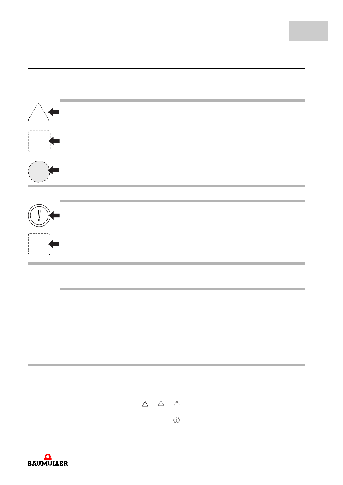
The following two examples show you how the hazard informations are constructed. The
triangle is used when indicating a hazard for h uman beings. When there is a circle instead
of the triangle, the hazard information is only for possible property damage.
A triangle indicates hazard for human beings.
The shade of grey of the outline reflects the severity of the hazar d - dar ker gr ey means rising
hazard.
The icon within the square illustrates the hazard.
The outline´s shade of grey reflects the severity of the hazard - darker grey mea ns rising hazard. (Not every hazard information has a square representing the hazard , so we have shown
it as draft here)
The icon in the circle represents a command.
(Not every hazard informat ion has a circle repres enting the ha zard, so w e have show n it as
draft here)
Fundamental safety instructions
2
The circle indicates hazard for property.
The icon within the square illustrates the hazard.
The outline´s shade of grey reflects the severity of the hazard - darker grey mea ns rising hazard. (Not every hazard information has a square representing the hazard , so we have shown
it as draft here)
The text beneath the icons is constructed as follows:
HERE STANDS THE SIGNAL WORD WHICH INDICATES THE DEGREE OF THE HAZARD
Here we tell if one or more of the consequences described lower will occur if this hazard information is not observed.
m here we describe the possible consequences. The worst consequence stands on the rig ht
side.
Here we describe the hazard.
Here we describe what you can do to avoid this hazard.
2.2.2 Form of the hazard sign (triangular or round)
If there is a triangle like or or in front of the signal word, the hazard information
is referring to personal damage.
If there is a round hazard signal like in front of the signal word, the hazar d information
is referring to property damage.
Manual b maXX® BM1000
Document No. 5.07003.06
11
of 172
Page 12
2.2
2.2.2.1 Hazard information on personal injury
Hazard information and commands
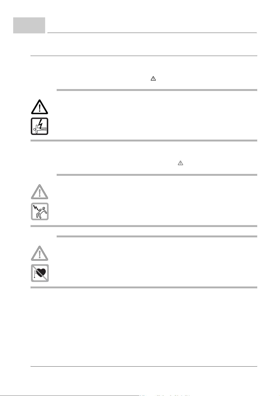
To distinguish each class of hazard information, we use a characterist ic outline for both
the triangular hazard signs and the square-form icons
For the hazard class DANGER the danger sign is used. The hazard information of
this hazard class used in this documentation is listed below:
DANGER
The following will occur, if you do not observe this danger information:
m serious personal injury m death
The hazard is: electricity. Here the hazard may be described in detail.
Here is described what you can do to avoid the ha za rd .
For the hazard class WARNING the warning sign is used. The following hazard information of this hazard class is used in this documentation.
WARNING
The following may occur, if you do not observe this warning information:
m serious personal injury m death
The hazard is: electricity. Here the hazard may be described in detail.
Here is described what you can do to avoid the ha za rd .
WARNING
The following may occur, if you do not observe this warning information:
m serious personal injury m death
The hazard is: electro-magnetic radiation. Here the hazard may be described in detail.
Here is described what you can do to avoid the ha za rd .
12
of 172
Manual b maXX® BM1000
Document No. 5.07003.06 Baumüller Nürnberg GmbH
Page 13
Fundamental safety instructions
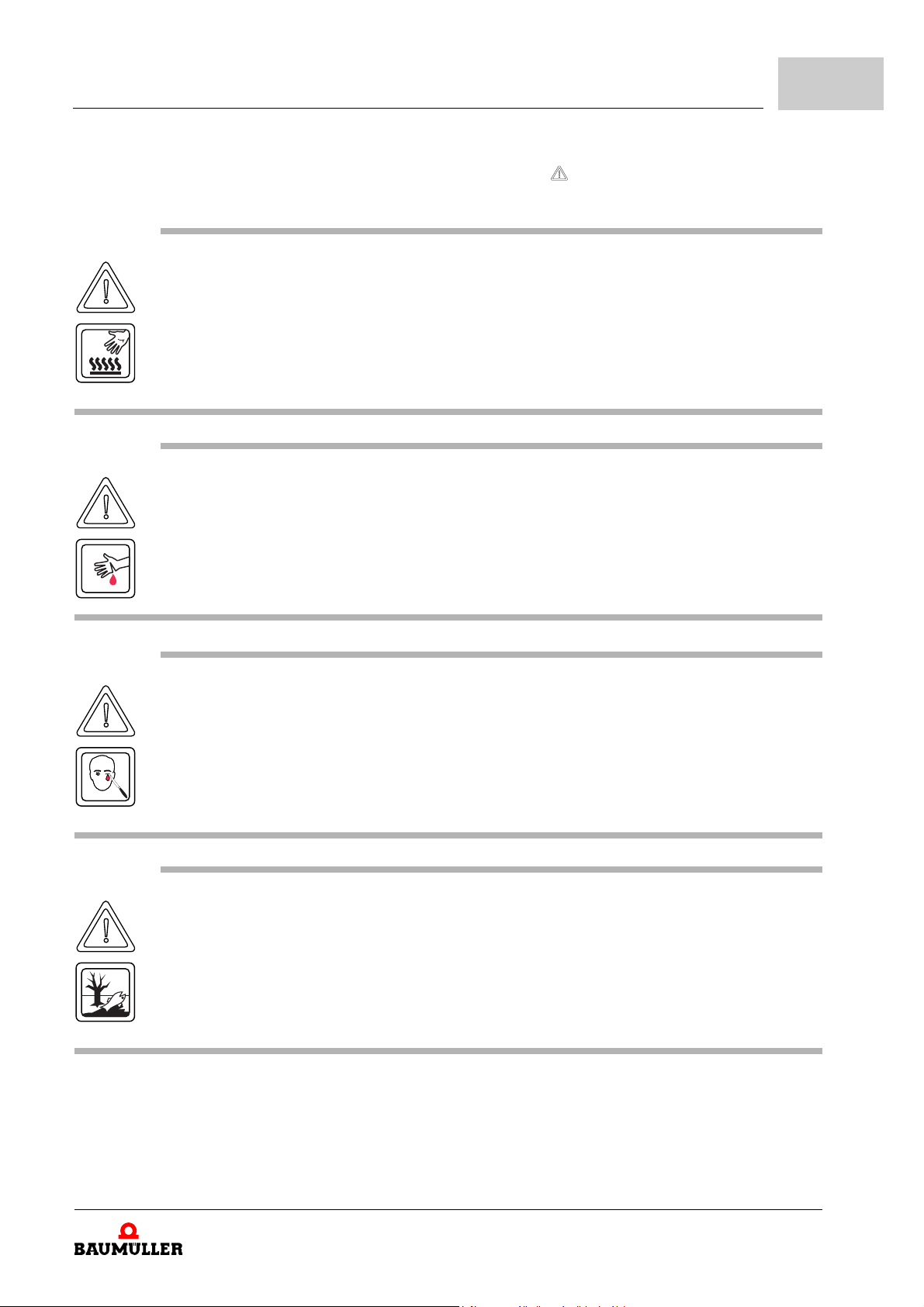
For the hazard class CAUTION the caution sign is used when there is hazard for persons or of environmental pollution. The following hazard information of this hazard class
is used in this documentation.
CAUTION
The following may occur, if you do not observe this caution information:
m minor to medium personal injury.
The hazard is: hot surface. Here the hazard may be described in detail.
Here is described what you can do to avoid the hazard.
CAUTION
The following may occur, if you do not observe this caution information:
m minor to medium personal injury.
The hazard is: sharp edges. Here the hazard may be described in detail.
Here is described what you can do to avoid the hazard.
2
CAUTION
The following may occur, if you do not observe this caution information:
m minor to medium personal injury.
The hazard is: injury of the eye caused by ricocheting particles. Here the hazard may be
described in detail.
Here is described what you can do to avoid the hazard.
CAUTION
The following may occur, if you do not observe this danger information:
m environmental pollution.
The hazard is: inadequate disposal. Here the hazard may be described in detail.
Here is described what you can do to avoid the hazard.
Manual b maXX® BM1000
Document No. 5.07003.06
13
of 172
Page 14

2.3
2.2.2.2 Hazard information on property damage
2.2.2.3 Command signs used
Information sign
If there is a round caution sign in front of the signal word, the safety information refers
to property damage.
CAUTION
The following may occur, if you do not observe this caution information:
m property damage.
The hazard is: electro-static discharge. Here the hazard may be described in detail.
Here is described what you can do to avoid the ha za rd .
wear safety gloves
wear safety shoes
wear eye protection
wear ear protection
Use this fire extinguishing agent:
„fire extinguishing agent“
2.3 Information sign
14
of 172
NOTE
This note is a very important information.
Manual b maXX® BM1000
Document No. 5.07003.06 Baumüller Nürnberg GmbH
Page 15

2.4 Legal instructions
This documentation is addressed to technical qualified personnel, who is specifically
skilled and who is thoroughly familiar with all warnings and maintenance procedures.
The devices are made according to the state-o f-the-art technology and are fail-safe. They
can be installed safe, can be put into operation and they function without problems, if it is
assured, that the instructions of the documentation are followed.
The user is responsible for the execution of service and commissioning according to the
safety instructions of the prevailing standards and other relevant national and local in
structions concerning conductor dimensioning and protection, earthing, disconnector,
overcurrent protection and so on.
For damages, which result from the moun ting or from the connection, the one is liable,
who has carried out the mounting or the installation.
2.5 Appropriate use
Always use the device according to the terms. Stated below we have carried a few important notes together. The notes stated below shall give you a feeling for the according to
the terms usage of the device. We do not raise any claim for the completion of the notes
stated below - follow all instructions given in this operating instruction.
m project the application in such a way, that you always operate the device within its
specification.
m use this device only as converter for drives.
m make sure, that only qualified personnel work with/at this device.
m install this device only on an adequate carrying wall.
m install this device in the way as it is described in the documentation.
m make sure, that the mains/power supply unit always applies to the predetermined
specifications.
m only operate the device, if it is technical faultlessly.
m operate this device only in combination with released components of the company
Baumüller Nürnberg GmbH.
m always operate the device in an area as it is instructed in the „Technical data“.
m always operate the device in serialized condition.
Due to safety reasons you must not rebuild the device.
m consider all instructions referring to this, if you intend to store the device.
You are using the device according to the terms, as soon as you regard all notes and in-
formation in this operating manual.
Fundamental safety instructions
2
-
Manual b maXX® BM1000
Document No. 5.07003.06
15
of 172
Page 16

2.6
Inappropriate use
2.6 Inappropriate use
Listed below you will find some examples of non-appropriate application. The information
below is intended to give you some impression of what non-appropriate application is.
However we cannot state all possible non-app ropriate applica tions here. All applications,
where the notes and information given in this documentation is disr egard ed, a re no n-ap
propriate and therefore forbidden.
Examples:
m You disregarded the notes in this manual.
m The device has not been specifically applied as a converter in order to control a motor.
n The device has been
m mounted incorrectly,
m connected incorrectly,
m commissioned incorrectly,
m operated incorrectly,
m mounted, connected, commissioned, operated and/or maintained by not qualified or
inadequately qualified personnel,
m inappropriately maintained or not maintained
(also consider the descriptions of the components),
m overloaded it,
n operated
m with defective safety devices,
m with incorrectly mounted safety devices or without safety devices,
m with incorrectly working safety- and protection devices,
m outside the specified environmental conditions.
m You have modified the device.
m You have insufficiently monitored the parts, which are subject to a wearing.
m You have improperly carried out a repair.
m You have combined the device with improper products, which are not enabled for de-
vices described in this manual.
m You have combined the device with faulty and/or faulty documentate d products of oth-
er manufacturers.
m The device has been operated in an explosive environment.
-
2.7 Safety equipment
The devices b maXX® BM1000 comply with the protection class IP 20.
WARNING
The following may occur, if you do not observe this warning information:
m serious personal injury m death
The danger is: electricity.
Operate the device in a control cabinet, which provides a protection against a direct touching
of the devices and fulfills at least the demands of the EN61800-5-1, chapter 4.2.3.3.
16
of 172
Manual b maXX® BM1000
Document No. 5.07003.06 Baumüller Nürnberg GmbH
Page 17
2.8 Training of the personnel
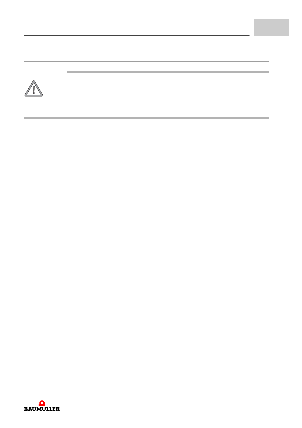
WARNING
The following may occur, if you do not observe this warning information:
m serious personal injury m death
Devices of the company Bau müller Nürnber g GmbH may only be assembled, installed,
operated and maintained by qualified personnel.
Qualified personnel (professionals) is defined below:
Fundamental safety instructions
2
Qualified
personnel
Requirements to
the operating per
sonnel
Authorized electronic engineers and skilled persons of the customer or third persons, who
have learned the installation and commissionin g of Baumüller drive systems and who are
authorized, to put circuits and devices into operation according to the standards of the
safety technology, to ground and to label.
Qualified personnel has a training or an instruction due to the local valid standards of th e
safety technique in maintenance and usage of an adequate safety equipment.
The operating of the drive system must only be executed by persons, who have had a
training, who have been instructed and who have been authorized for this.
Fault clearance, servicing, cleaning, maintenance and exchange must only be carried out
by skilled or instructed personnel. These persons must know the operating manual and
must act according to this.
The commissioning as well as the instruction must only be carried out by qualified personnel.
2.9 Safety precautions in normal operation
h at the location of your appliance regard the safety regulations for the plant, into which
the appliance has been built in.
h if safety regulations require additional monitoring or safety devices supply your appli-
ance with them.
2.10 Dangers due to residual energy
Electrical
residual energy
Mechanical
residual energy
After separation of the device from the mains parts under voltage as e. g. power connections may be only then touched if the capacitors in the device are d ischarged. To pr event
personal injury, please ensure that power has been turned off before opening the
b
maXX® BM1000 and wait ten minutes for the capacitors to discharge to safe voltage
levels.
The mechanical residual energy is dependent upon the application. As we don't know the
application, we cannot make any exact statements. Driven parts also rotate/move after
disconnection of the mains supply for a certain time. Please, provide ad equate safety ar
rangements.
Manual b maXX® BM1000
Document No. 5.07003.06
-
17
of 172
Page 18
2.11
Disposal of the device
2.11 Disposal of the device
The accurate disposal of the device is described in Z12 Disposal– on page 111.
2.12 Fire fighting
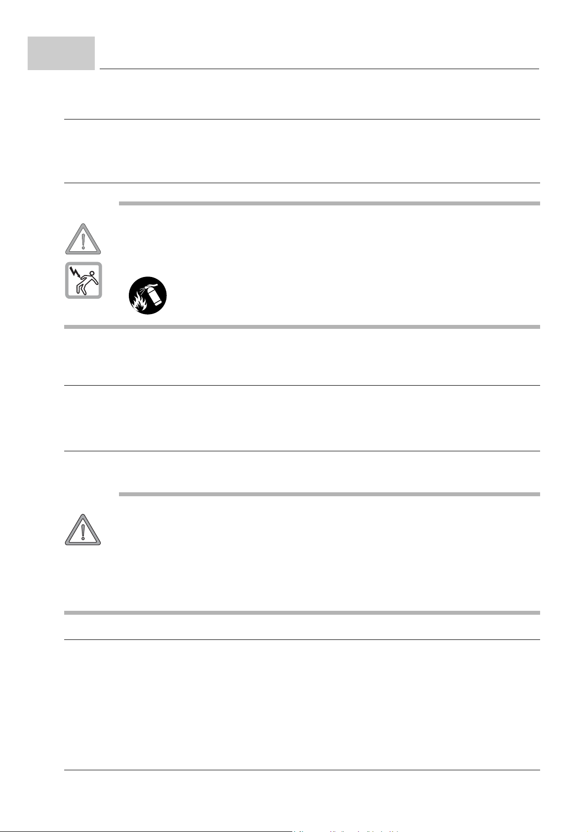
WARNING
The following may occur, if you do not observe this warning information:
m serious personal injury m death
The danger is: Electricity when using a conductive fire fighting appliance.
Use this fire extinguishing agent:
ABC powder / CO
2
2.13 Responsibility and liability
To be able to work as safe as possible with this device, you must know and follow the
danger notes as well as the safety instructions.
2.13.1 Observing the safety notes and safety instructions
In this manual we use visually unified safety instructions, which are intended to prevent
from personal injury or damage to property.
WARNING
The following may occur, if you do not observe this warning information:
m serious personal injury m death
All persons, who work with this device, must know and regard the safety notes and the safety
instructions in this manual.
Apart from this, any and all persons who work on this device must additionally know and re-
gard to all regulations and instructions, that are valid at the location.
2.13.2 Dangers when handling this device
The device „b maXX®“ was developed and manufactured according to the state-of-theart technology and in compliance with the valid regulations and standards. It is still pos
sible that dangers can arise during use. An overview of possible dangers is to be found
in chapter
We warn you against the acute danger at the respective places in this manual.
ZFundamental safety instructions– from page 9.
-
18
of 172
Manual b maXX® BM1000
Document No. 5.07003.06 Baumüller Nürnberg GmbH
Page 19

2.13.3 Warranty and Liability
All information in this manual is non-binding customer information; it is subject to ongoing
further development and is updated on a continuous basis by our revision service.
Warranty- and liability claims against Baumüller Nürnberg GmbH are excluded if in particular one or more of the causes listed in ZInappropriate use– from page 16 has/have
caused the damage.
Fundamental safety instructions
2
Manual b maXX® BM1000
Document No. 5.07003.06
19
of 172
Page 20

2.13
Responsibility and liability
20
of 172
Manual b maXX® BM1000
Document No. 5.07003.06 Baumüller Nürnberg GmbH
Page 21
3TRANSPORTATION AND PACKING
In this chapter we describe, which conditions have to be adhered to at transportation, how
you check the device after receipt and what you should have to consider, if you dispose
the packing.
3.1 To be considered by transportation
For the first transportation of the device, the device was packed in the manufacturer com pany. In case you transport the device, assure, that the following conditions are fulfilled
during the whole transportation:
m -20°C to +60°C (temperature range)
m max. 1 g (vibration, shock, repetitive shock)
3.2 Unpacking
After receipt of the device, which is still packed:
h Avoid strong transportation vibrations and severe hits, e.g. when setting down.
h Check, if transportation damages are visible!
If so:
h Immediately complain to the deliverer. Let the claim be confirmed in writing and imme-
diately contact the substitution of Baumülle r Nürnberg GmbH, which is in charge for
your company.
WARNING
The following may occur, if you disregard these safety notes:
m serious personal injury m death
The danger is: electricity.
Do not operate the device, if you have recognized a transportation damage or if you assume
this. In this case immediately contact Baumüller Nürnberg GmbH
Manual b maXX® BM1000
Document No. 5.07003.06
of 172
21
Page 22

3.3
Dispose packing
If there is no transportation damage recognizable:
h Open the packing of the device.
h Check the scope of supply with the help of the delivery note.
The minimum scope of supply is:
m b maXX® BM1000
m This manual inclusively the copy of the declaration of conformity/declaration of manu-
facturer
h Claim at the Baumüller substitution, which is in charge, in case the delivery is not com-
plete.
3.3 Dispose packing
The packing is made of cardboard, plastics, metal parts, corrugated cardboard and/or
wood.
h Regard the local disposal instructions, in case you dispose the packing.
22
of 172
Manual b maXX® BM1000
Document No. 5.07003.06 Baumüller Nürnberg GmbH
Page 23
NOTE
The devices of the b maXX® BM1000- series are provided for the operation in the ’second environment’ (industrial environment) according to EN 61800-3. At connection to the public
mains EMC problems can appear. Also see
4.1 Structure
NOTE
The b maXX® BM1000 is to be used to control 3-pha se asynchronous standard motors in the
power range of 0.2 to 11
4DESCRIPTION OF THE DEVICES
In this chapter the basic construction of the device b maXX® BM1000 is described and
the type key on the devices is explained.
ZAppropriate use– from page 15.
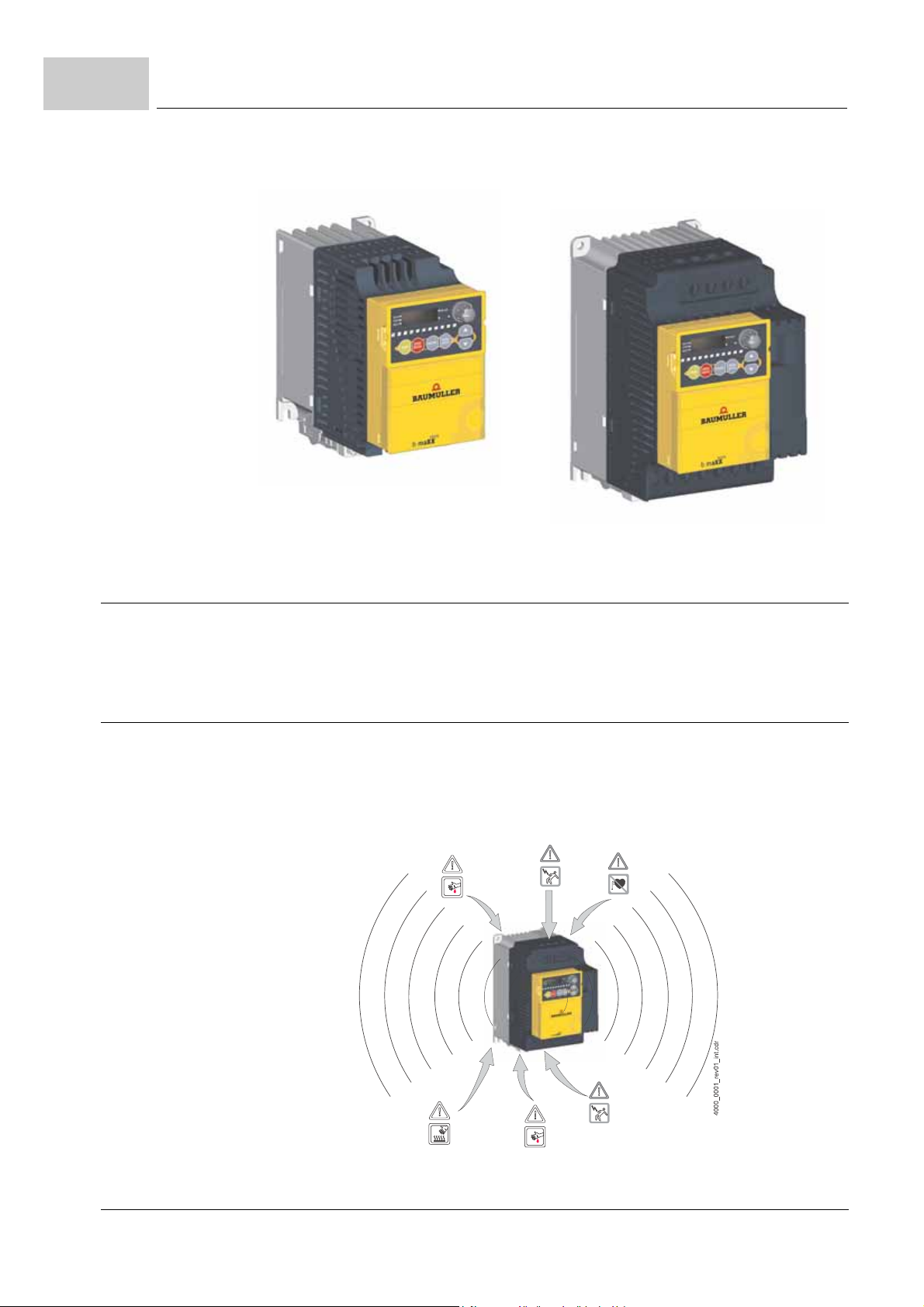
The devices of the b maXX®-series are converters of Baumüller Nürnberg GmbH. The
devices consist of a power unit with an integrated controller.
The rated current of the devices reach for 1-phase devices from 1.6 A to 11 A and for 3phase devices from 1.5 A to 24 A. The devices differ in size, power and cooling.
kW (rated power of the drive).
Manual b maXX® BM1000
Document No. 5.07003.06
23
of 172
Page 24
4.2
Interconnect the devices
This data is available in the type key (see ZMarking of the device - type key– on page 25).
Figure 1: b maXX® BM1000
4.2 Interconnect the devices
The device is part of the Baumüller series b maXX® BM1000 and can be connected together with other Baumüller devices.
4.3 Overview of dangerous areas
The following overview shows the existing dange r areas on the particular device. Use this
survey for an overview of the existing danger areas, if you incorporate into the handling
of this device. The explanation of the symbols, which are used you will find in
information and commands– from page 10.
ZHazard
24
of 172
Figure 2: Danger areas b maXX® BM1000
Manual b maXX® BM1000
Document No. 5.07003.06 Baumüller Nürnberg GmbH
Page 25
4.4 Marking of the device - type key
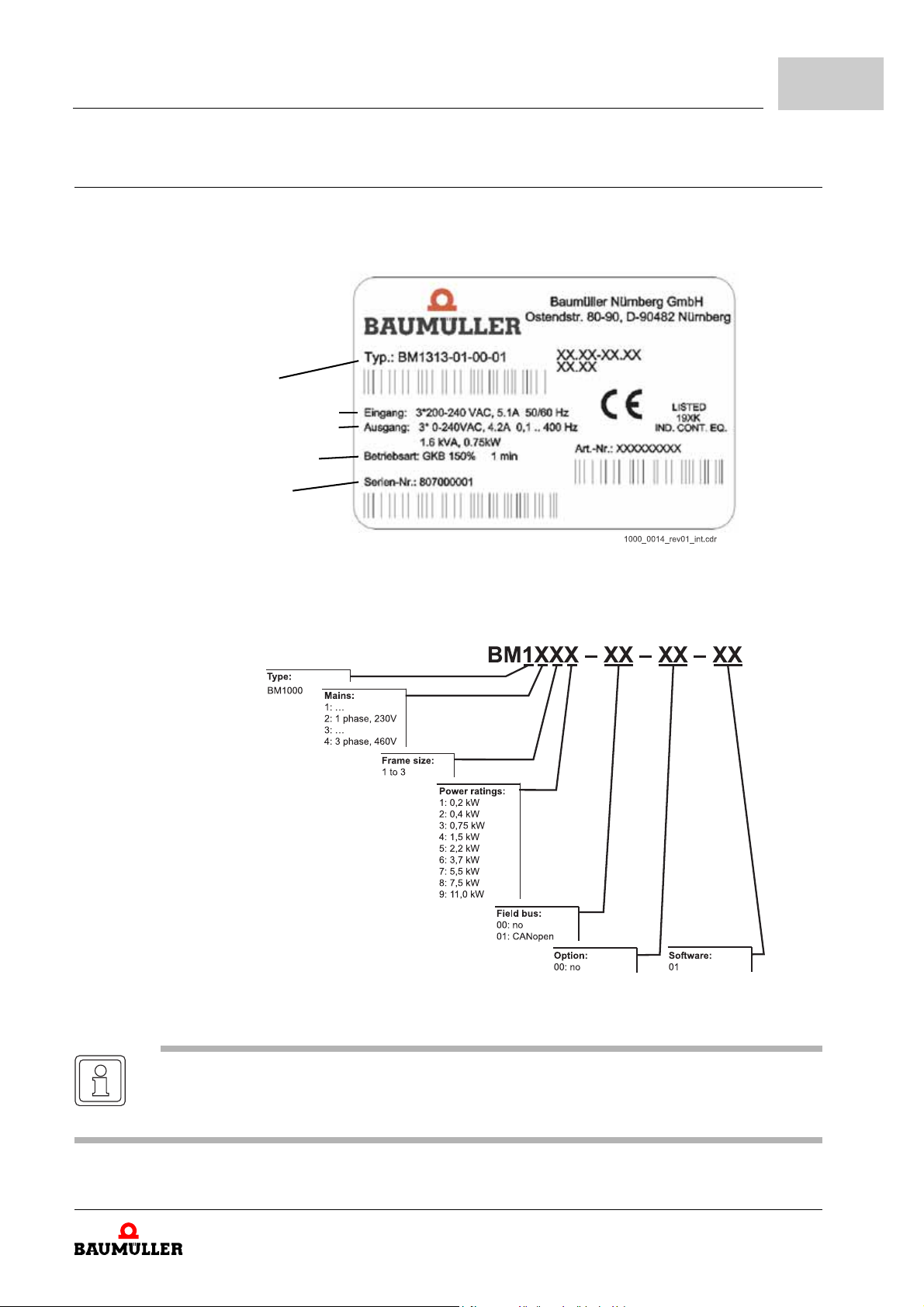
On the type plate (label) you will find, besides others, the type key of the device.
Type key
Input specification
Output specification
Operation mode
Serial No.
Description of the devices
4
Figure 3: Type plate BM1000
m Type key
Figure 4: Type key BM1000
NOTE
If the type key information does not correspond to your purchase order or if there are any
problems, please contact your distributor.
Manual b maXX® BM1000
Document No. 5.07003.06
of 172
25
Page 26
4.4
Marking of the device - type key
m Drive frames
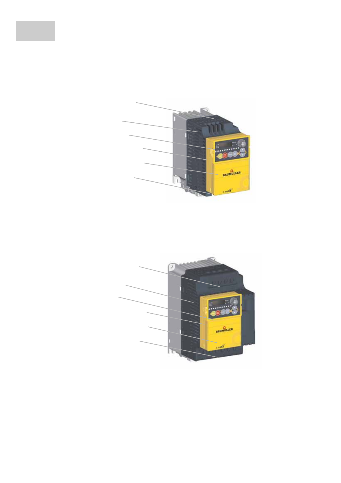
n Frame 1 (0,2 -1,5 kW)
Input Terminals
(R/L1, S/L2, T/L3)
Housing
Keypad
Control board case
Control board cover
Output terminals
(U/T1, V/T2, W/T3)
Figure 5: b maXX® BM1000 Frame 1
n Frame 2 (0,75 - 3,7 kW)
Input Terminals
(R/L1, S/L2, T/L3)
Housing
Keypad
Control board case
Control board cover
Output terminals
(U/T1, V/T2, W/T3)
Figure 6: b maXX® BM1000 Frame 2
26
of 172
Manual b maXX® BM1000
Document No. 5.07003.06 Baumüller Nürnberg GmbH
Page 27
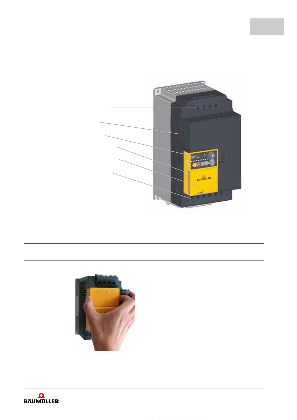
n Frame 3 (5,5 - 11,0 kW)
Input Terminals
(R/L1, S/L2, T/L3)
Housing
Keypad
Control board case
Control board cover
Output terminals
(U/T1, V/T2, W/T3)
Description of the devices
4
Figure 7: b maXX® BM1000 Frame 3
4.5 Preparation for installation and wiring
4.5.1 Remove keypad
Figure 8: Remove keypad
Manual b maXX® BM1000
Document No. 5.07003.06
27
of 172
Page 28
4.5
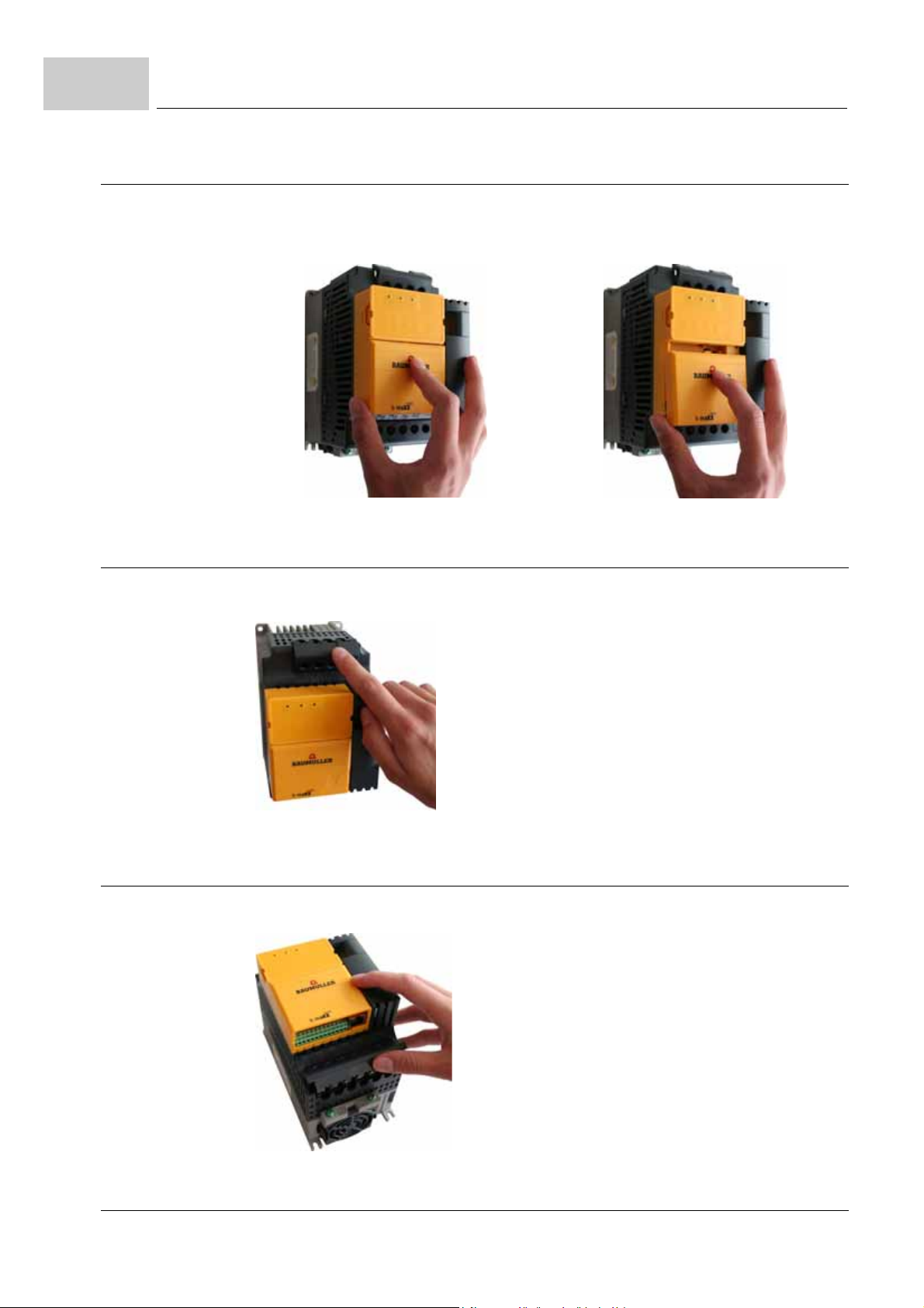
4.5.2 Remove front cover
Preparation for installation and wiring
Step 1 Step 2
Figure 9: Remove front cover
4.5.3 Remove main terminal cover
Frame 2 and frame 3
Figure 10: Remove mains terminal cover
4.5.4 Remove motor terminal cover
Frame 2 and frame 3
28
of 172
Figure 11: Remove motor terminal cover
Manual b maXX® BM1000
Document No. 5.07003.06 Baumüller Nürnberg GmbH
Page 29
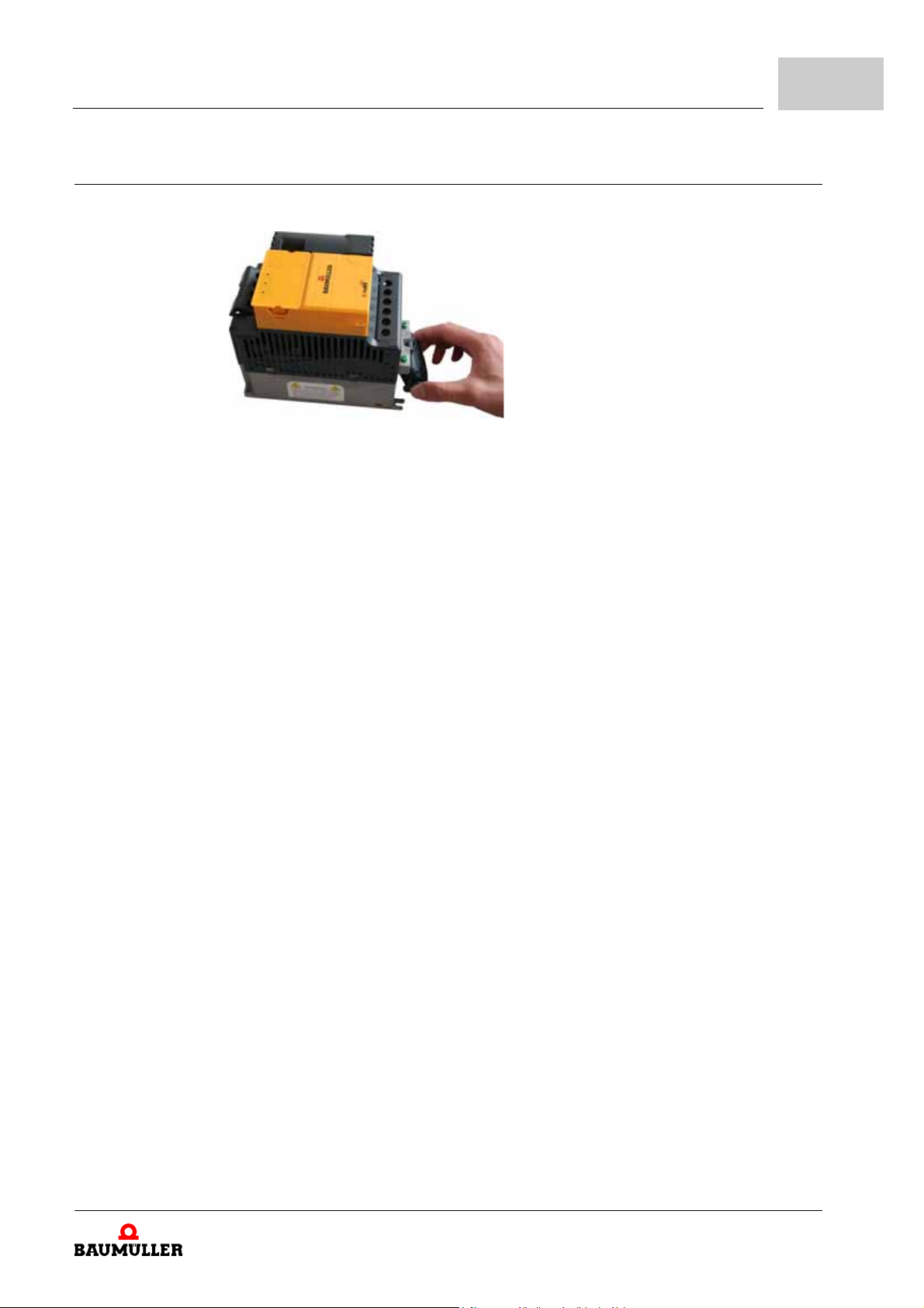
4.5.5 Remove fan
Figure 12: Remove fan
Description of the devices
4
Manual b maXX® BM1000
Document No. 5.07003.06
29
of 172
Page 30

4.5
Preparation for installation and wiring
30
of 172
Manual b maXX® BM1000
Document No. 5.07003.06 Baumüller Nürnberg GmbH
Page 31
In this chapter we describe the mechanical mounting of the device into a control cabine t.
Data about the installation space is available in this manual (see
from page 34).
Mounting consists of the following steps:
1 Prepare mounting (drill holes/cut-out segments)
2 Install device
WARNING
The following may occur, if you do not observe this warning information:
m serious personal injury m death
At execution of any mounting workings it must be assured that no strange substances (e.g.
drilling chips, copper wire etc.) get into the device. If possible the drillings should be done be
fore mounting the device and the assembling of the cables should be done outside the control
cabinet. If this is not possible, the device must be covered accordingly.
5.1 General safety instructions
5MOUNTING
ZInstallation space–
-
CAUTION
The following may occur, if you disregard these safety notes:
m Property damage
The danger is: electrostatic discharge. Connections of the device sometimes are dangerous to ESD.
Regard the corresponding notes.
h Please regard to the information in chapter ZFundamental safety instructions– from
page 9.
Manual b maXX® BM1000
Document No. 5.07003.06
of 172
31
Page 32
5.2
Requirements to the executing personnel
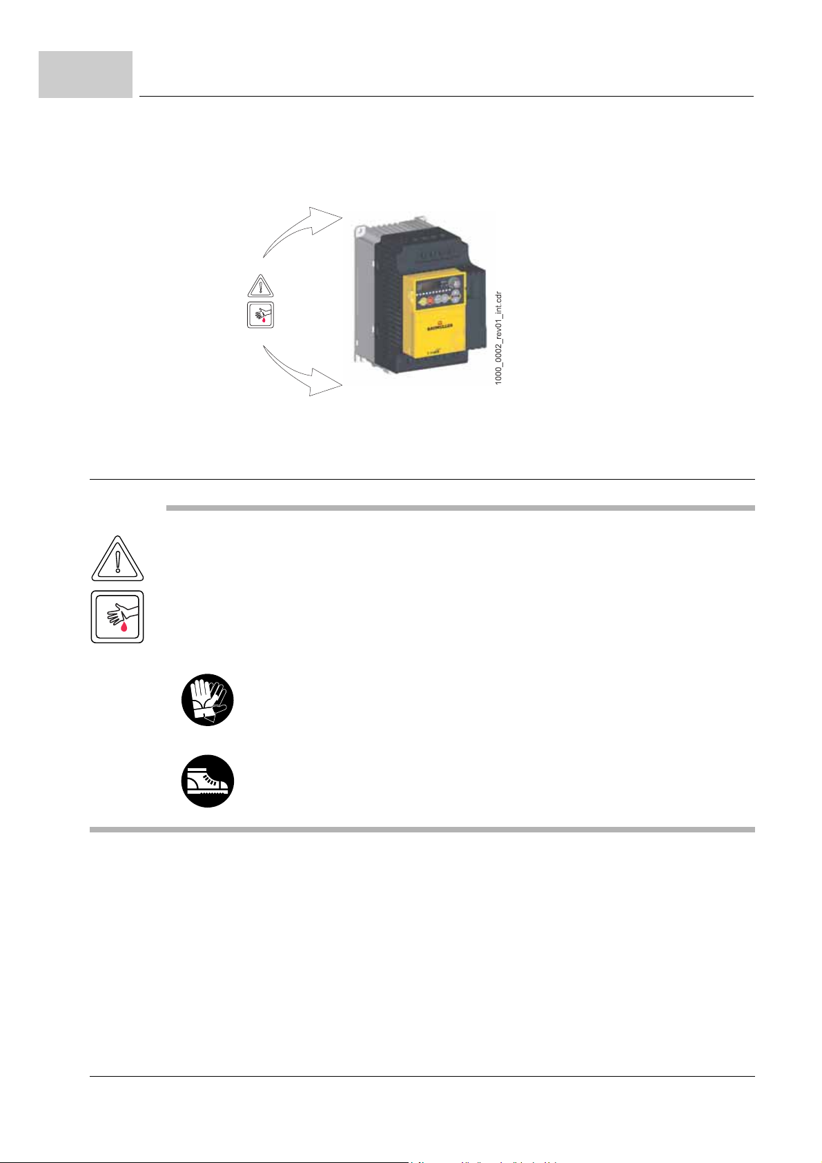
h Pay attention to all areas at the device, which could be dangerous for you while mount-
ing. Use this survey only for the mechanical mounting. Dangers, which, for example,
result from electricity are not shown here.
Figure 13: Danger areas by the mechanical mounting
5.2 Requirements to the executing personnel
CAUTION
The following can occur, if you disregard this warning instruction:
m minor to medium personal injury.
The danger is: sharp edges. In case, while installing, you lift a device with unprotected hands,
fingers/palm can be cut. If the device falls off, your feet can be cut up.
Make sure, that only qualified personnel, who is familiar with the safety- as well as with mounting instructions, works on this unit.
Wear safety gloves
Wear safety shoes
Qualified personnel are persons, who have been instructed by the responsible person,
based on their training, experience, the instructions they were given as well as their
knowledge about relevant standards and instruction s, knowledge of the accident preven
tion instructions and of the company, to execute the necessary operations and thereby
are able to recognize and avoid the dangers which could hap pen. The requ ired qualifica
tions for the work with this unit are for example:
m Training or instruction due to the standards of the safety engineering in maintenance
and use of appropriate safety equipm en t.
-
-
32
of 172
Manual b maXX® BM1000
Document No. 5.07003.06 Baumüller Nürnberg GmbH
Page 33
5.3 Prepare mounting
You can prepare the mounting with the configuring manual for your installation. With the
project manual and the drill figures (see
the dimensions for the cut-outs and for the fastening drills.
CAUTION
The following can occur, if you disregard this warning instruction:
m minor to medium personal injury.
The danger is: Eye injury due to catapulting particles. While executing the drillings and the
cut-out metal particles are catapulted.
Wear eye protection
h Please carry only fully assembled b maXX® 1000 to prevent machine damage.
h Execute the drilling and if necessary the cut-outs.
Mounting
ZDimensions– from page 37) you can de termine
5
h Mount the b maXX® 1000 vertically on a flat vertical surface by using bolts or screws.
Other directions are not allowed.
h The b maXX® 1000 will generate heat during operation. Allow sufficient space around
the unit for heat dissipation.
h The heat sin k t em p er at ur e may rise to 90°C when runn ing . Th e m at er ial on wh ich t he
b maXX
temperature.
h When the device is installed in a confined space (e.g. cabinet), the surrounding tem-
perature must be within 10 to 40°C with good ventilation. DO NOT install the device in
a space with bad ventilation.
h When installing multiple devices b maXX® 1000 in the same cabinet, they should be
adjacent in a row with enough space. When installing one b maXX
other one, use a metal separation barrier between the b maXX® 1000 to prevent mutual heating. Refer to figure below for details.
h Prevent fiber p articles, scraps of pa per, saw dust, metal pa rticles, etc. from ad hering
to the heatsink.
®
1000 is mounted must be noncombustible an d be able to withstand this hig h
®
1000 below an-
Manual b maXX® BM1000
Document No. 5.07003.06
33
of 172
Page 34
5.4
Air flow
Air flow
Installation space
5.4 Installation space
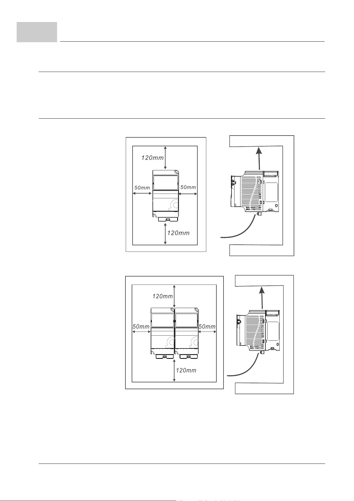
The following drawings show the main dimensions of the devices in mm. Use these drawings, in order to determine the required space in the control cabinet. For the construction
of the necessary drilling/cut-outs use the drawings in
5.4.1 Installation space frame 1
Option 1 (-10 to +50°C)
ZDimensions– from page 37.
Option 2 (-10 to +40°C)
Figure 14: Installation space frame 1
34
of 172
Manual b maXX® BM1000
Document No. 5.07003.06 Baumüller Nürnberg GmbH
Page 35
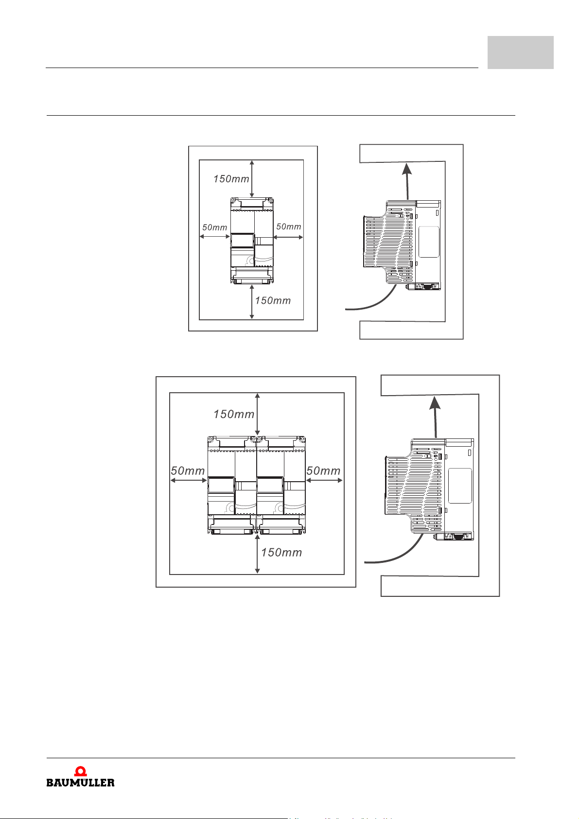
5.4.2 Installation space frame 2 and 3
Air flow
Air flow
Option 1 (-10 to +50°C)
Mounting
5
Option 2 (-10 to +40°C)
Figure 15: Installation space frame 2 and 3
Manual b maXX® BM1000
Document No. 5.07003.06
35
of 172
Page 36
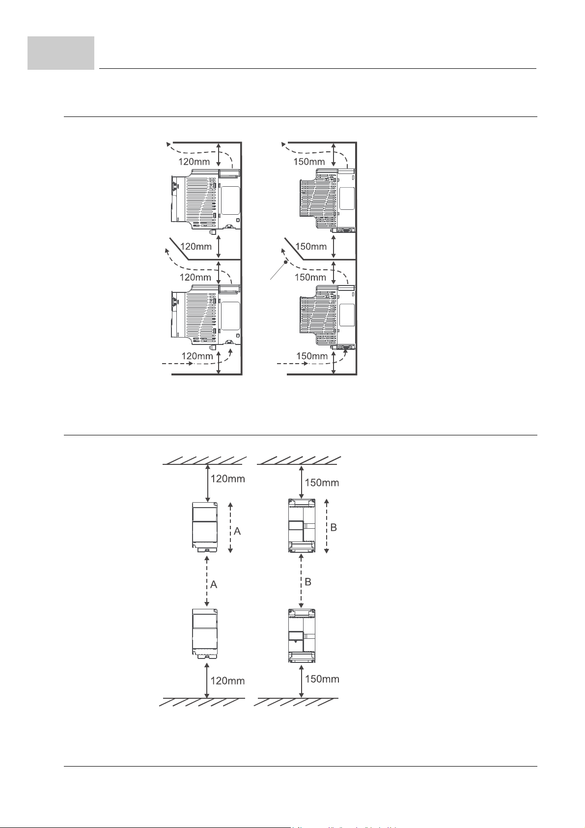
5.4
Air flow
5.4.3 Installation with metal separation
Installation space
Frame 1 Frame 2 and 3
Figure 16: Installation with metal separation
5.4.4 Installation without metal separation
36
of 172
Frame 1 Frame 2 and 3
Figure 17: Installation without metal separation
Manual b maXX® BM1000
Document No. 5.07003.06 Baumüller Nürnberg GmbH
Page 37
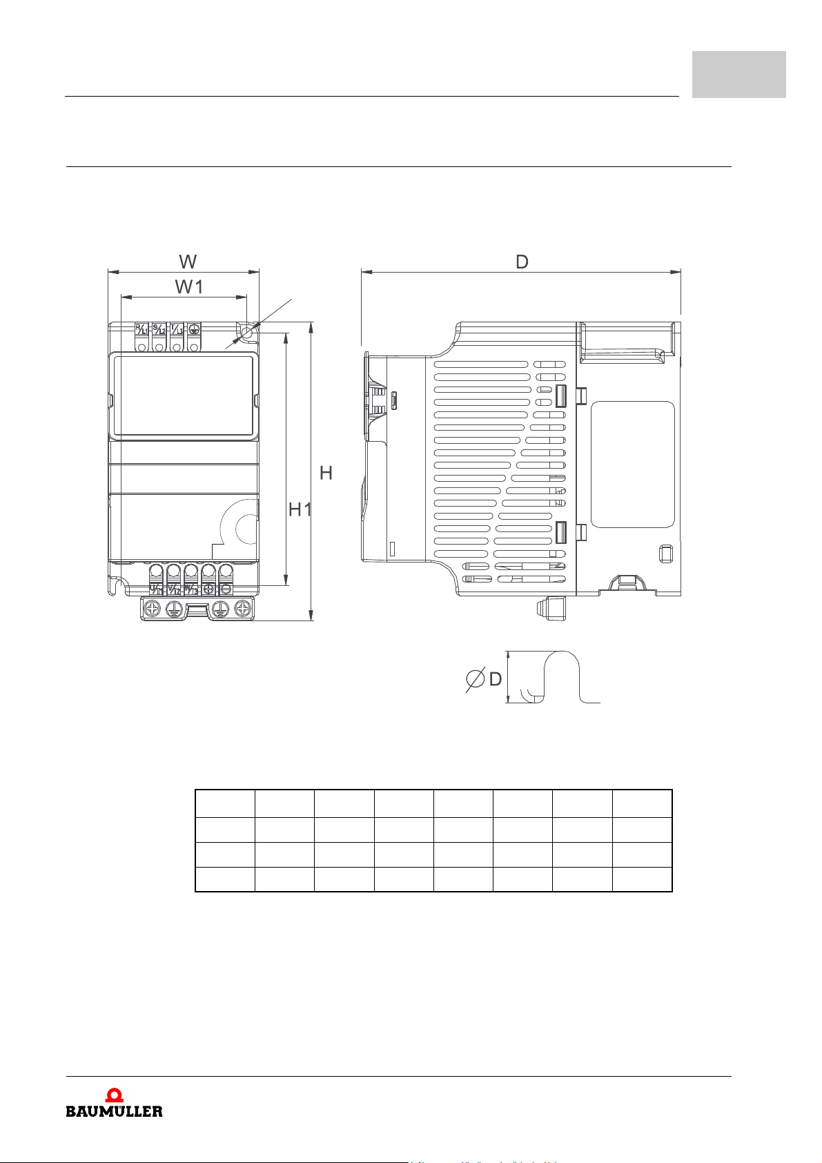
5.5 Dimensions
Mounting
The following drawings show the dimensions of the devices. Use these drawings, to pre pare the necessary drilling/cut-outs. Use the drawings under ZInstallation space– from
page 34, to determine the required space in the control cabinet.
5
Figure 18: Dimensions
Frame W W1 H H1 D
1 72.0 60.0 142.0 120.0 152.0 5.2 7.6
2 100.0 89.0 174.0 162.0 152.0 5.5 9.3
3 130.0 116.0 260.0 246.5 169.0 5.5 9.8
Manual b maXX® BM1000
Document No. 5.07003.06
∅ D∅
37
of 172
Page 38
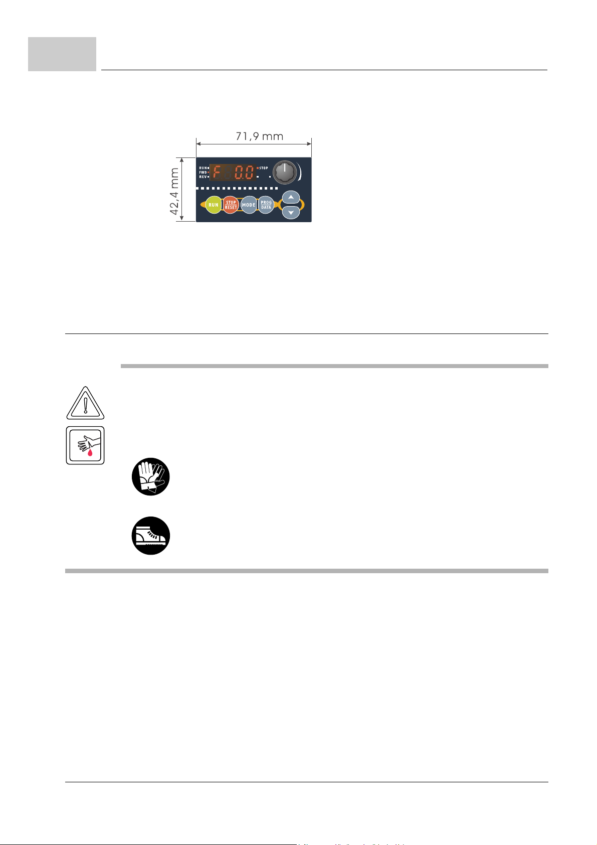
5.6
Mounting instructions
m Operation terminal (option keypad):
Depth: 28,8 mm
Figure 19: Dimension operation terminal
5.6 Mounting instructions
CAUTION
The following may occur, if you disregard these safety notes:
m minor to medium personal injury.
The danger is: sharp edges. In case, while installing, you lift a device with unprotected hands,
fingers/palm can be cut. If the device falls off, the feet can be cut.
Wear safety gloves
Wear safety shoes
Complete the mounting in the following way:
1 provide suitable mounting accessories
2 mount the device.
38
of 172
Manual b maXX® BM1000
Document No. 5.07003.06 Baumüller Nürnberg GmbH
Page 39
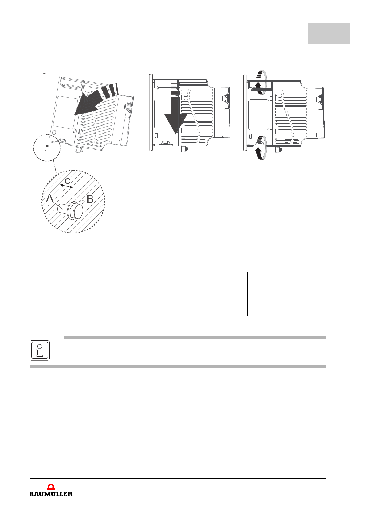
Mounting
5
Figure 20: Mounting instruction
Device Frame 1 Frame 2 Frame 3
A - screws 2 x M4 4 x M4 4 x M5
B - washers 2 x (4.3 x 10) 4 x (4.3 x 10) 4 x (5.3 x 10)
C - mount spacing c = 12 mm c = 12 mm c = 16 mm
NOTE
Spare parts for DIN-rail mounting see ZB.8 DIN rail– on page 132.
Manual b maXX® BM1000
Document No. 5.07003.06
39
of 172
Page 40

5.6
Mounting instructions
40
of 172
Manual b maXX® BM1000
Document No. 5.07003.06 Baumüller Nürnberg GmbH
Page 41
In this chapter we describe the electric installation of the device. The mechanical installation is described in ZMounting– from page 31.
Before installing assure, that the technical preconditions are fulfilled:
1 Check the requirements to the electrical mains and check if the existing mains is suit-
able.
2 Check the requirements to the electrical cables and provide the according cables.
3 Check the characteristics of the connections and configure the connections according-
ly.
6.1 General safety instructions
h Pay attention to the information in the chapters ZFundamental safety instructions–
from page 9.
h Pay attention to all areas at the device, which could be dangerous for you during the
electrical installation.
6INSTALLATION
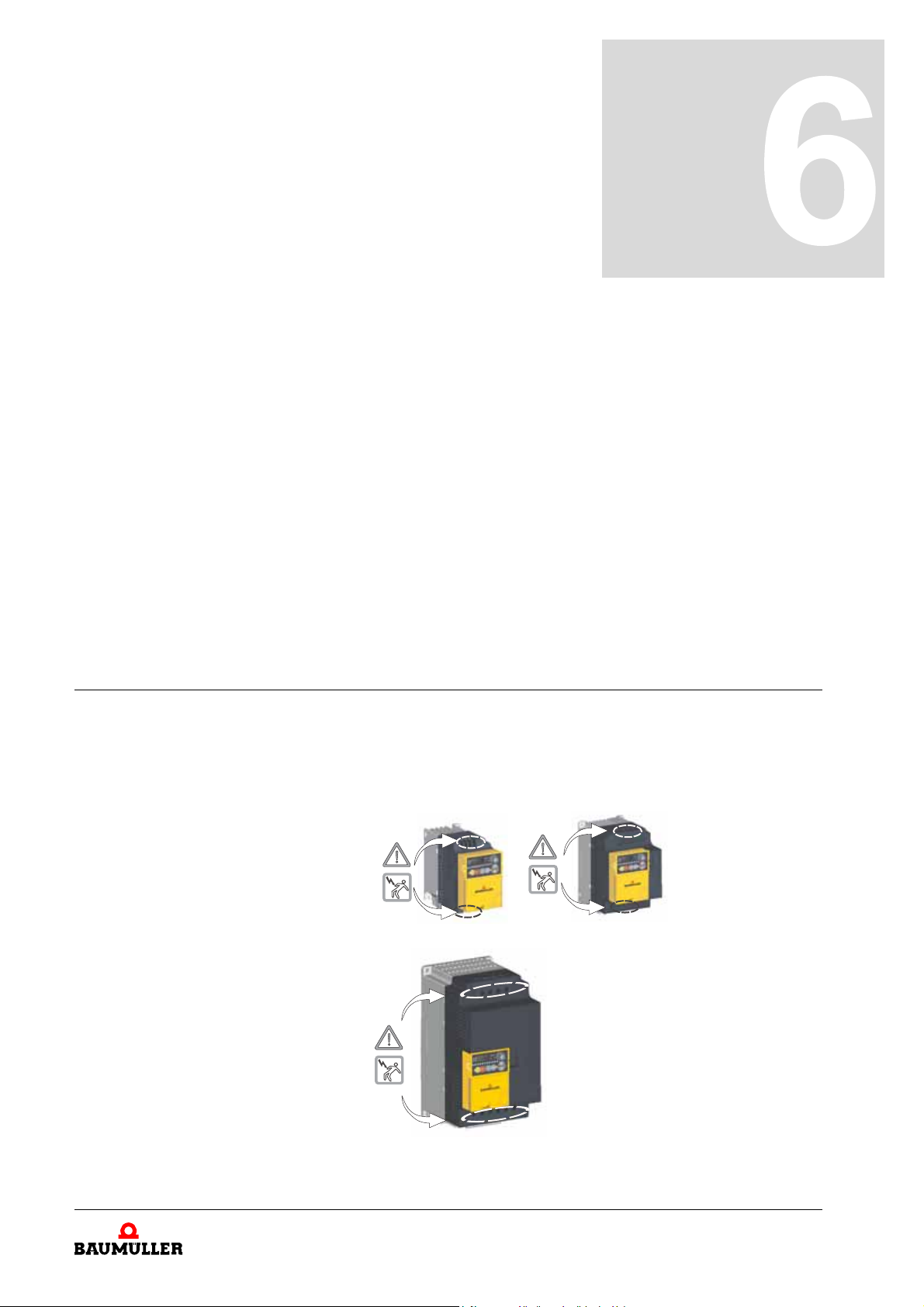
Figure 21: Danger areas at the electrical installation
Manual b maXX® BM1000
Document No. 5.07003.06
41
of 172
Page 42
6.2
Requirements to the executing personnel
6.2 Requirements to the executing personnel
WARNING
The following may occur, if you disregard these safety notes:
m serious personal injury m death
The danger is: electricity. When operating with this electrical unit, inevitably certain parts of
this unit are under dangerous voltage.
Make sure, that only qualified personnel, who are familiar with the safety- as well as with
mounting-, operating- and maintenance instructions, work on this unit.
At each case qualified personnel are persons, who are authorized by the responsible persons, to execute necessary actions and who recognize the possible danger s and who are
able to avoid these dangers. They have had the training, the experience, they were given
instructions as well as knowledge about the relevant standards and instructions, they
have knowledge of the accident prevention regulations and of the operating environ
ments. The required qualifications for the work with this unit are for example:
m Education or instruction or to have the authorization to put into operation, ground and
label circuits and devices according to the standards of safety engineering.
m Training or instruction due to the standards of the safety engineering in maintenance
and use of appropriate safety equipm en t.
-
6.3 Requirements to the electrical mains
All important data is to be found in ZD.3 Electrical data– on page 141. Small deviations
of the electrical mains from the requirements can lead to malfunctions of the device. In
case the mains deviates strongly from the req uirements, the device can be destroyed.
b
maXX® BM1000-devices must not be opera ted in low-voltag e mains in o rder to supply
buildings in residential areas. The destruction of the device can cause personnel injury.
WARNING
The following may occur, if you disregard these safety notes:
m serious personal injury m death
The danger is: electricity. In case you do not ensure the requirements to the electrical mains,
the device can be damaged/destroyed and can thereby endanger persons severely.
Assure before installation, that the requirements of the electrical mains are fulfilled.
42
of 172
Manual b maXX® BM1000
Document No. 5.07003.06 Baumüller Nürnberg GmbH
Page 43
6.4 Requirements to the connecting cables
h Always use shielded cables
h You must consider IEC/EN 60204-1, chapter 13 at selection of connection cables.
h The protective conductor cross section of the cable must be executed accordant to
IEC/EN 60204-1, section 5.2, tab. 1.
h The permanent connection of the protective conductor is imperatively regulated for the
operation of the device.
h Use a copper cable for at least 60°C (drives < 3 x 100 A) incase you consider UL 508 C.
6.5 Protection of the device and of the cable respectively
In order to protect the device or the cables a gainst damage/destruction by the mains, you
must install fuses. Data of the necessary fuses are to be found in
from page 144.
Installation
ZD.5 Fuse protection–
6
6.6 PE connection and RCD compatibility
Due to the operating principle leakage current can flow via the protective conductor
>
3.5 mAAC or > 10 mADC. On this account a permanent protective conductor is prescribed. In addition to the plugged protective connection, the screw terminal, which is
marked with „PE“ must be connected to the PE (see
46).
WARNING
The following may occur, if you disregard these safety notes:
m serious personal injury m death
This product can cause direct current in the prote ctive conductor.If, in case of a direct or indirect contact a residual-current-operated protective device (RCD) is used, then a RCD of type
B is permitted on the power supply side only. Otherwise other safety precautions must be
made as e. g. environment al separation with a double or str engthened insulation or by the
separation of the power supply with an isolated transformer.
Due to high leakage currents, which arise due to the operating principle of the device, ca n
result in an early enabling of the RCD or generally can avoid an enable.
ZConnection diagrams– from page
Manual b maXX® BM1000
Document No. 5.07003.06
43
of 172
Page 44
6.7
Requirements on the laying (EMC notes device)
6.7 Requirements on the laying (EMC notes device)
NOTE
The emission of radio interferences is to a high level dependent on the wiring, the volume expansion and the arrangement of the components in the in stallation. That is why the assurance
of the electromagnetic compatibility according to the statutory provisions only is possible on
the completed installation and therefore is in the responsibility range of the manufacturer of
the installation or of the operating authority (EMVG § 6, sec. 9).
NOTE
In this Manual the most important information for an EMC-compatible installation is available.
Further notes, which necessarily have to be considered in order to mount a CE-conform in
stallation are to be found in the manual ’filters for mains applications’.
m Use Baumüller motor cables (shielded) and Baumüller components.
m Use a suitable mains filter of Baumüller Nürnberg GmbH
m Mount all components to one single mounting board with well electroconductive sur-
face (e. g. galvanized steel plate).
m Execute the ground connection converter/gr ound plane as short as po ssible (< 30 cm)
with fine-wired cables and a great cross section (> 10 mm
m When installing, attend to the correct order:
Mains - fuse -mains reactor - filter - b maXX® 1000 - motor)
m Assure, that the motor cables always consist of one piece.
Do not interrupt the motor cables e. g. by terminals, contactors, fuses a.s.o.
m Run the cables directly on the surface of the grounded mounting board.
(smallest possible effective aerial height).
m Keep a minimum clearance of 20 cm between signa l and control wires towards electric
power cables at parallel laying.
m Cross cables with different EMC categories (signal cables - supply cables or motor ca-
bles) only in a 90° angle.
m Contact the external cable screens when passing through walls, which separate differ-
ent EMC ranges.
m Connect the cable shields of the b maXX®-devices plane on both ends and highly con-
ductive with ground.
-
2
).
44
of 172
Manual b maXX® BM1000
Document No. 5.07003.06 Baumüller Nürnberg GmbH
Page 45
6.8 Operating sequence of installation
WARNING
The following may occur, if you disregard these safety notes:
m serious personal injury m death
The danger is: electricity. Parts, which are under tension are perilous.
Assure, that during the entire mounting the device, the parts, which must be m ounted (e. g.
supply cables) and the mounting range are off-circuit.
All the units must be grounded directly to a common ground terminal to prevent electric shock,
fire and interference.
The following steps must be carried out at installation:
1 Lay all cables EMC-compatible.
2 Connect cables (see ZConnection diagrams– from page 46)
m Connect the motor via the terminals U/T1, V/T2, W/T3, PE. Attend to the in-phase
connection (rotational direction).
m Connect the fuses.
(in case you consider UL 508 C: use the semiconductor- or total-range-fuses, which
are UL-listed in chapter
m Connect the mains filter (if necessary).
m Connect the reactors (if necessary)
m Connect the device via the mains input terminals R/L1, S/L2 and T/L3.
m Connect the protective conductor to the terminal PE (a permanent PE connection is
required imperatively).
m Perhaps connect (dependent on the application) a braking r esistor (RB) or a chopper
unit.
Installation
ZD.5 Fuse protection– from page 144.)
6
NOTE
Users must connect wires according to the circuit diagrams on the following pages.
Always use shielded cables.
Do not plug a modem or telephone line to the RS-485 communication port or p ermanent dam-
age may result. Terminals 1 and 2 are the power supp ly for the optional copy keypad only and
should not be used for RS-485 communication.
Manual b maXX® BM1000
Document No. 5.07003.06
of 172
45
Page 46
6.9
Connection diagrams
6.9 Connection diagrams
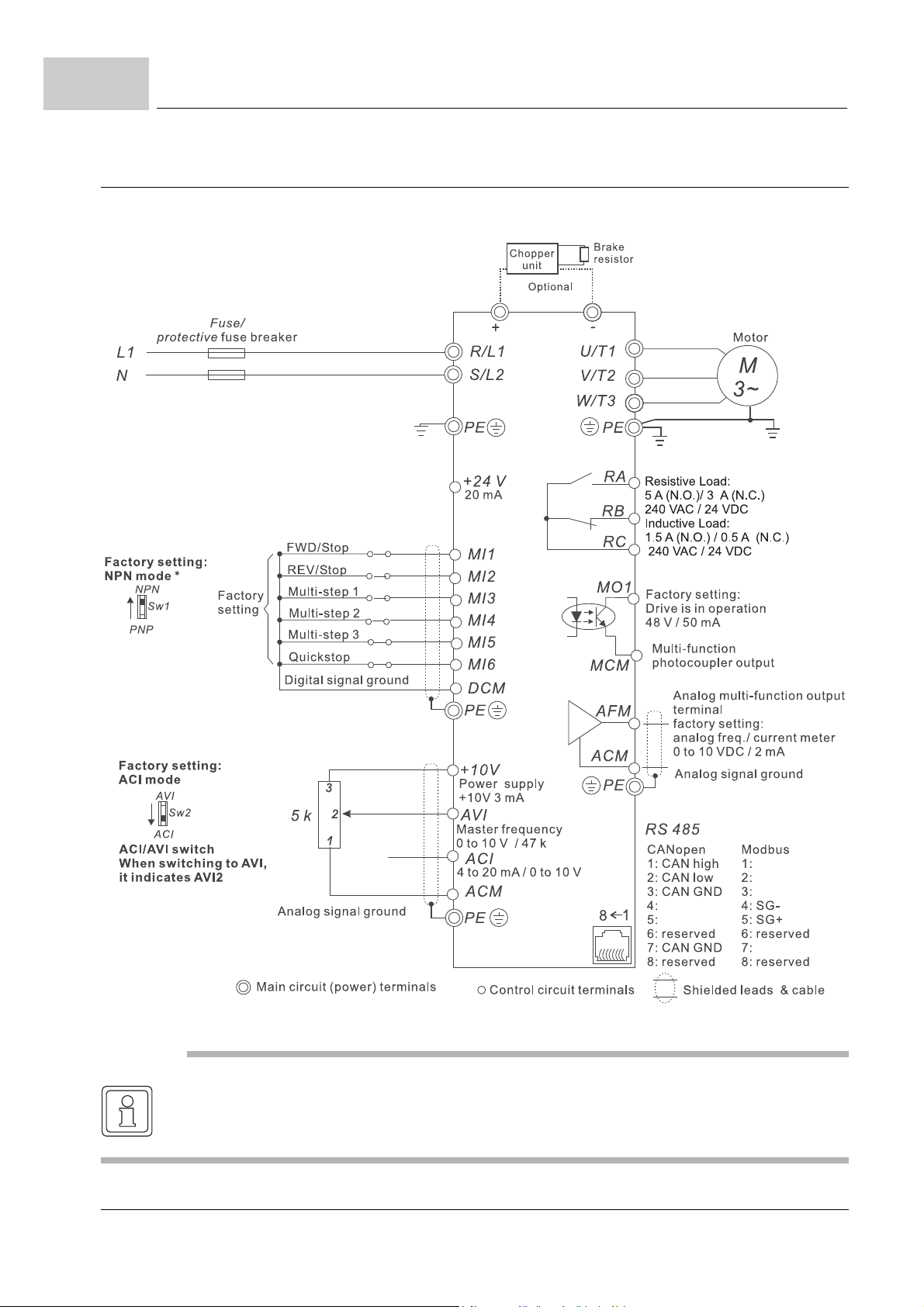
m BM1211, BM1212, BM1213
46
of 172
*: Please refer to ZFigure 22– on page 50 for wiring of NPN mode and PNP mode.
NOTE
Single-phase models can only use R/L1, S/L2 to be the power terminals.
Single-phase power cannot be used for 3-phase models.
Manual b maXX® BM1000
Document No. 5.07003.06 Baumüller Nürnberg GmbH
Page 47
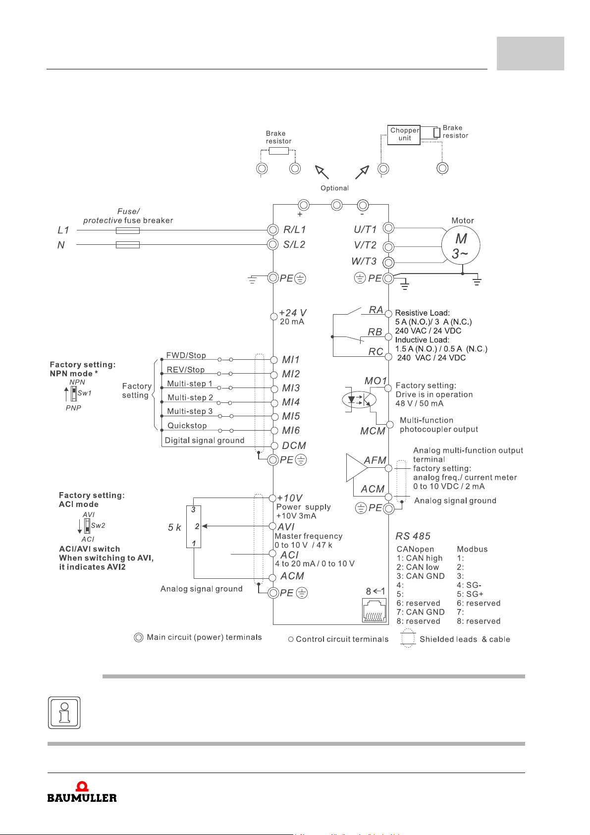
m BM1224, BM1225
Installation
6
*: Please refer to ZFigure 22– on page 50 for wiring of NPN mode and PNP mode.
NOTE
Single-phase models can only use R/L1, S/L2 to be the power terminals.
Single-phase power cannot be used for 3-phase models.
Manual b maXX® BM1000
Document No. 5.07003.06
47
of 172
Page 48
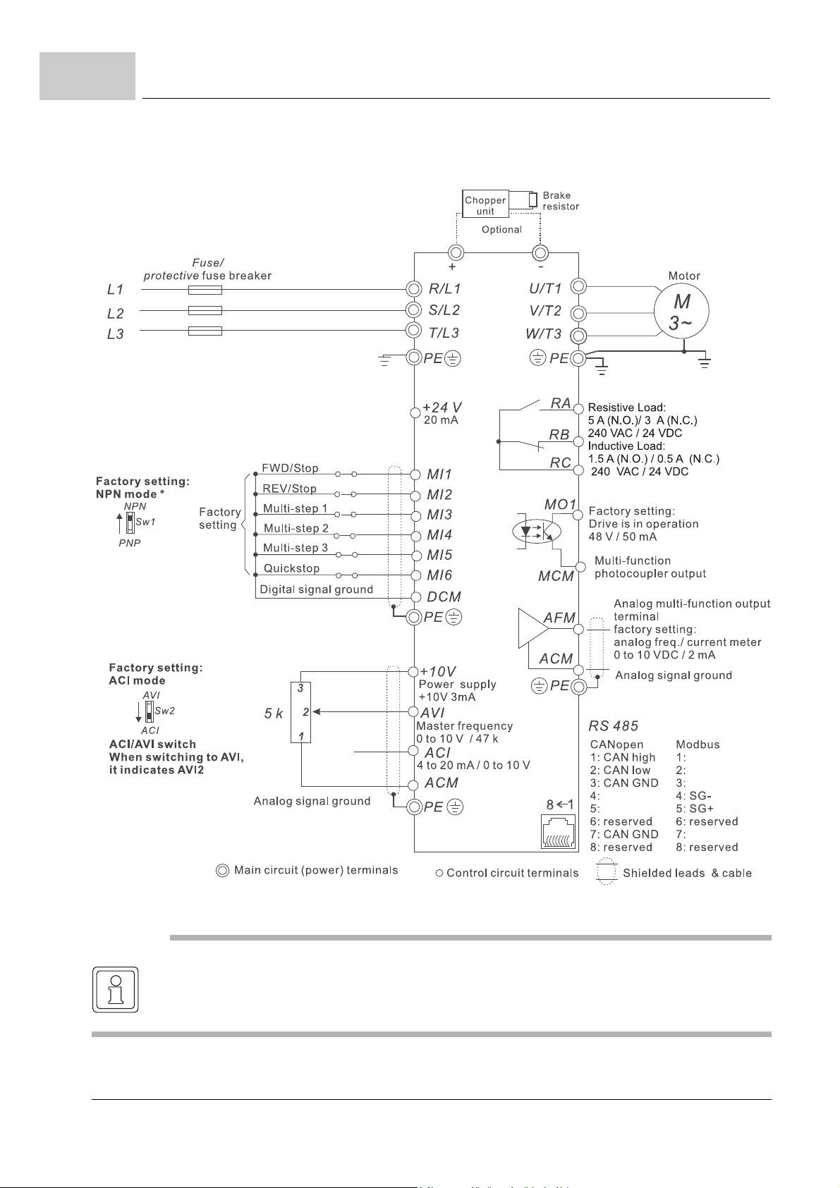
6.9
Connection diagrams
m BM1412, BM1413, BM1414
48
of 172
*: Please refer to ZFigure 22– on page 50 for wiring of NPN mode and PNP mode.
NOTE
Single-phase models can only use R/L1, S/L2 to be the power terminals.
Single-phase power cannot be used for 3-phase models.
Manual b maXX® BM1000
Document No. 5.07003.06 Baumüller Nürnberg GmbH
Page 49
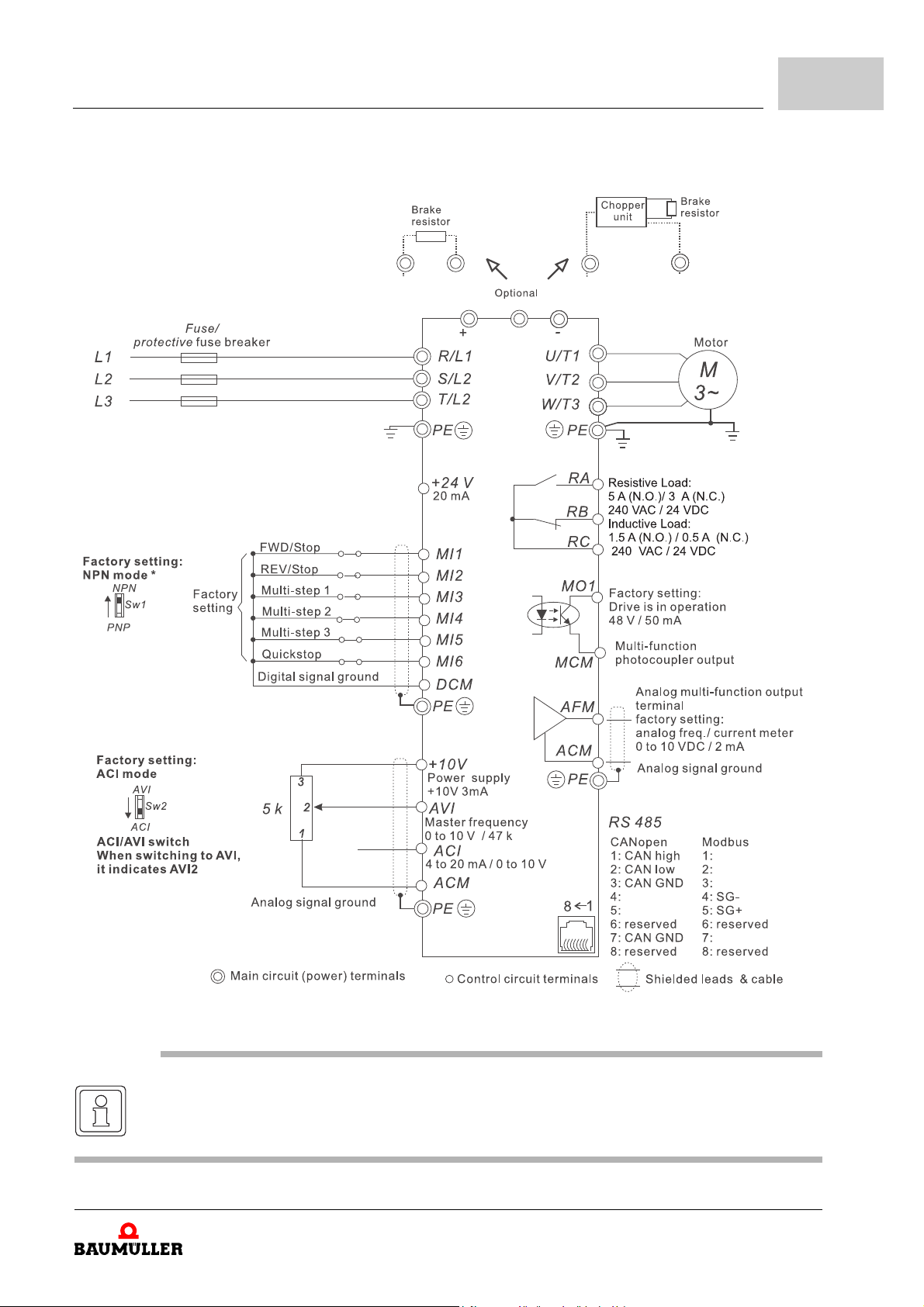
m BM1425, BM1426, BM1437, BM1438, BM1439
Installation
6
*: Please refer to ZFigure 22– on page 50 for wiring of NPN mode and PNP mode.
NOTE
Single-phase models can only use R/L1, S/L2 to be the power terminals.
Single-phase power cannot be used for 3-phase models.
Manual b maXX® BM1000
Document No. 5.07003.06
49
of 172
Page 50
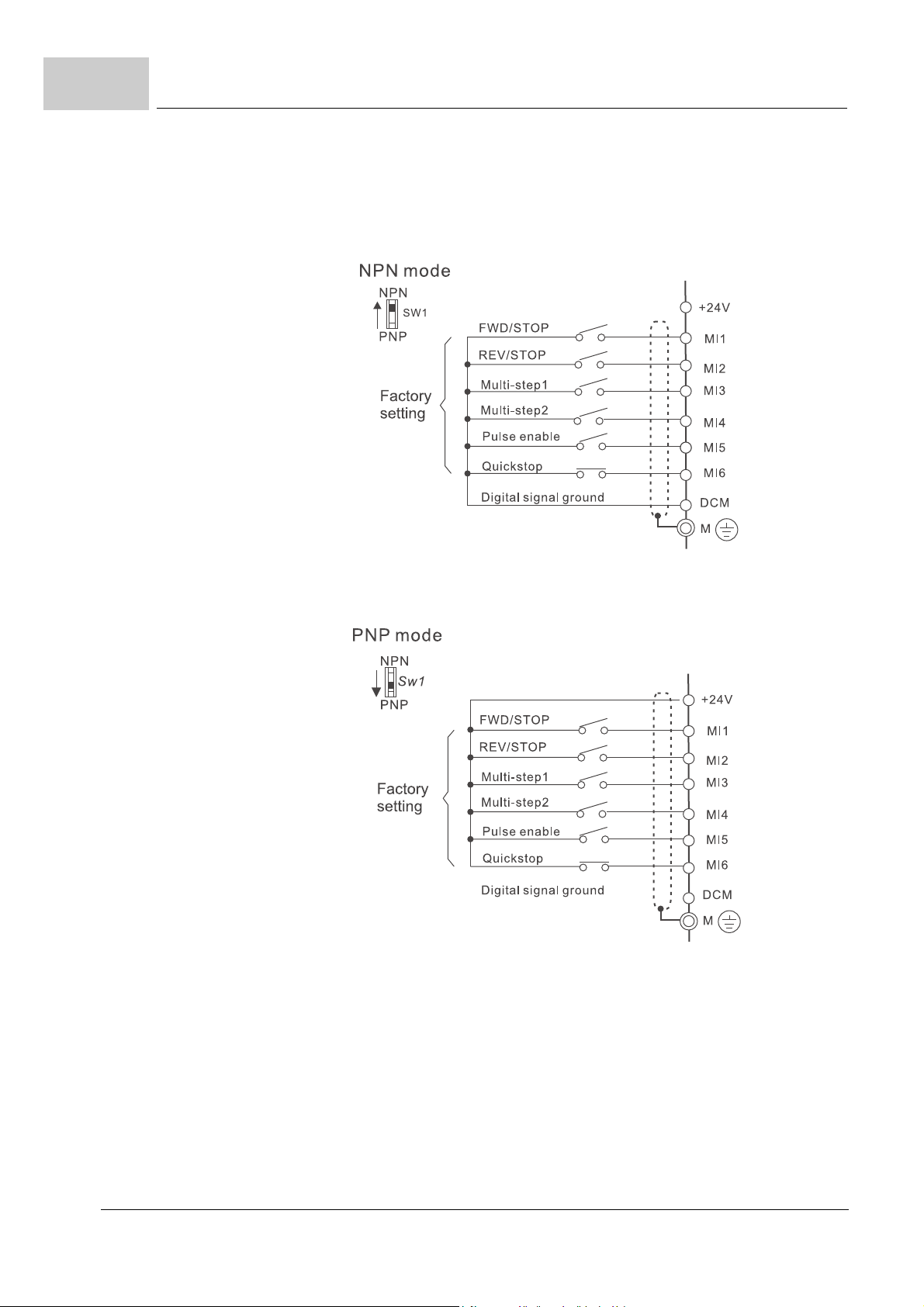
6.9
Connection diagrams
Wiring for NPN mode and PNP mode
m without external power
50
of 172
Figure 22: Connection NPN mode and PNP mode - without external power
Manual b maXX® BM1000
Document No. 5.07003.06 Baumüller Nürnberg GmbH
Page 51
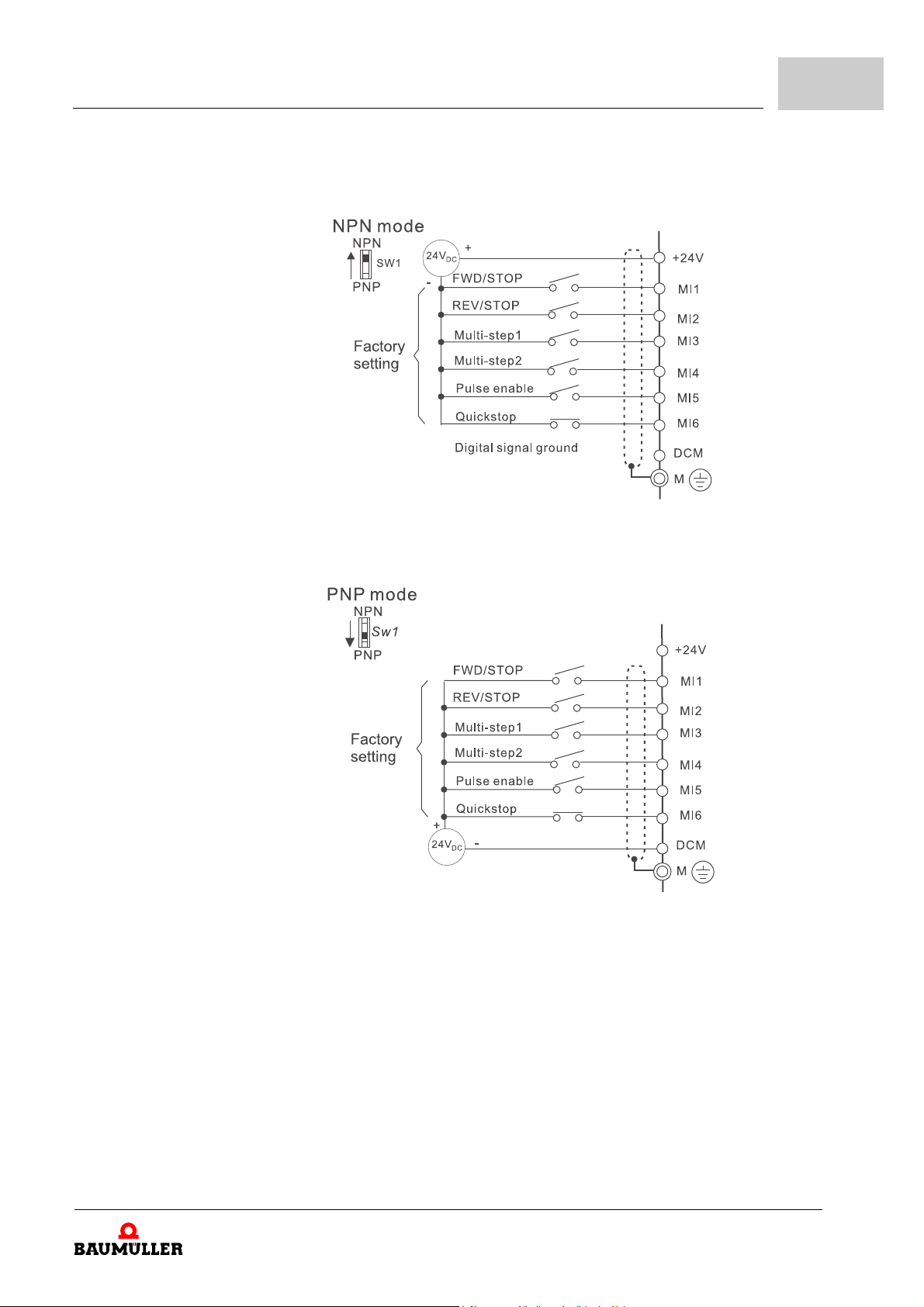
m with external power
Installation
6
Figure 23: Connection NPN mode and PNP mode - with external power
Manual b maXX® BM1000
Document No. 5.07003.06
51
of 172
Page 52
6.10
External connections
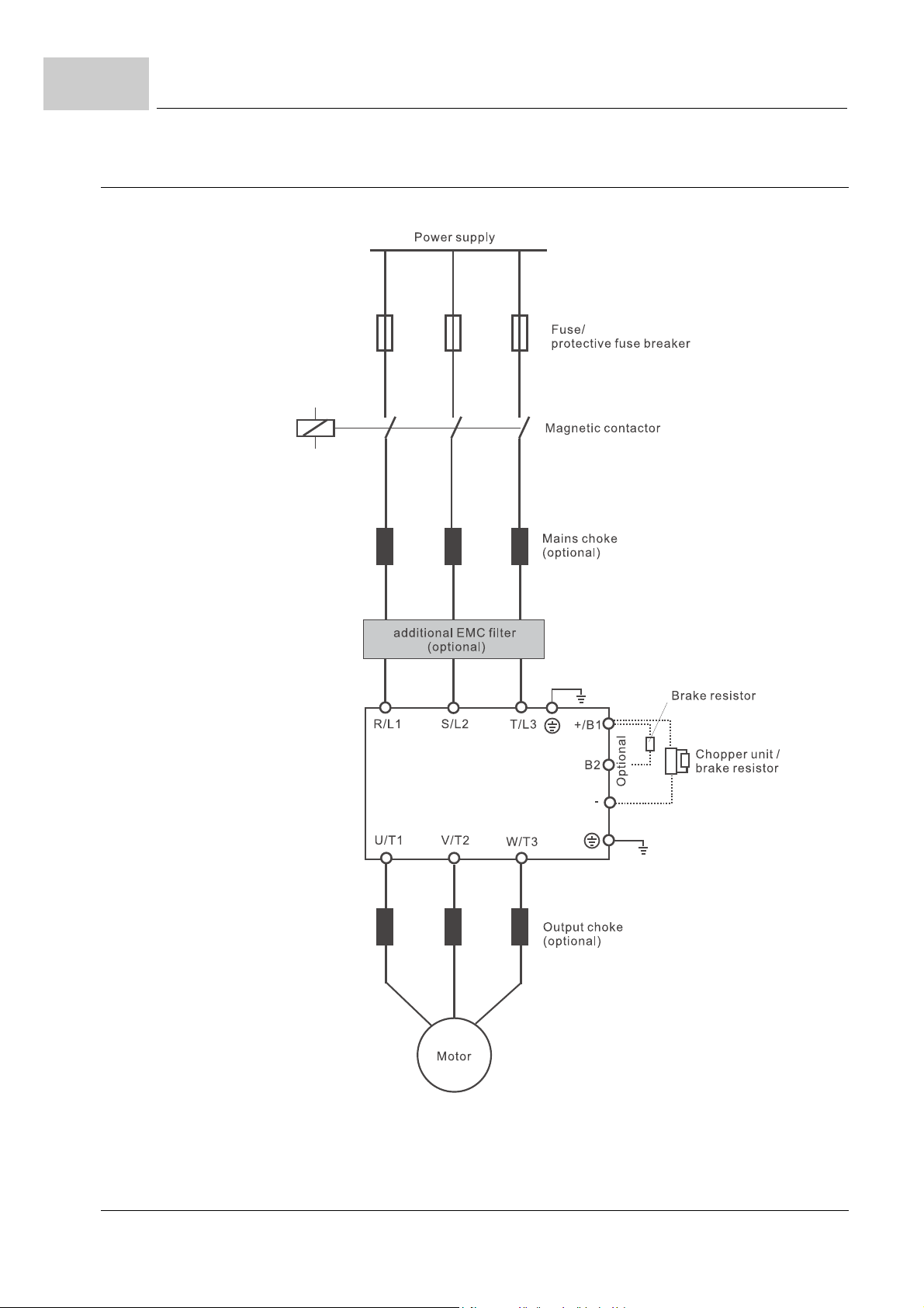
6.10 External connections
52
of 172
Figure 24: External connections
Manual b maXX® BM1000
Document No. 5.07003.06 Baumüller Nürnberg GmbH
Page 53

Installation
Items Explanations
Power supply Please follow the specific power supply requirements shown in ZD.3 Electrical
data– from page 141
6
Fuse/protective fuse
breaker (optional)
Magnetic contactor
(optional)
Mains choke (optional) Used to improve the input power factor, to reduce harmonics and provide protec-
Additional EMC filter
(optional)
Chopper unit/
braking resistor
(optional)
There may be an inrush current during power up. Please check the chart of ZD.5
Fuse protection– from page 144 and ZB.4 Fuses for device-protection– on page
130 to select the correct fuse. Use of an protective fuse breaker is optional.
Please do not use a magnetic contactor to switch on/off the b maXX® BM1000
during device operation, as it will reduce the operating life cycle of the device.
tion from mains interferences. (surges, switching spikes, short interruptions, etc.).
The mains choke should be installed when the power supply capacity is 500
or more and exceeds 6 times the device capacity, or the mains wiring distance
≤10 m. See Z6.15 Applications for mains chokes– on page 67 an d ZB.3.1 Mains
chokes recommended values– on page 128 for further information.
To reduce electromagnetic interference.
NOTE
The models b maXX® 1000 have an built-in EMI filter. An additional mains filter is
necessary for cable lengths > 15 m (cable device - motor).
For further information see ZB.2 Mains filters– on page 127.
Used to reduce the deceleration time of the motor.
m Frame 1:
No built-in chopper unit:
Use of chopper unit and braking resistor necessary (refer to ZB.1.1 Select a
chopper unit /braking resistor– from page 118.
m Frame 2 and 3:
Built-in chopper unit:
Connection of a suitable braking resistor (see ZB.1.1 Select a chopper unit /
braking resistor– from page 118) possible.
If the motor generates additional regeneration energy a further chopper unit
with braking resistor can be connected.
kVA
Output choke (optional) Motor surge voltage amplitude depends on motor cable length.
For applications with long motor cable, it is necessary to install a choke at the
device output side.
230V 1-phase: 0,4 kW and smaller: max 15 m.
0,75 kW and higher: max 50 m.
400V 3-phase: 0,75 kW and smaller: max 20 m.
1,5 kW and higher: max 50 m.
For more information see ZB.3.2 Output chokes recommended values– on page
129.
Manual b maXX® BM1000
Document No. 5.07003.06
53
of 172
Page 54
6.10
6.10.1 Specifications of main circuit terminals
External connections
Frame 1 Frame 2 Frame 3
Figure 25: Mains circuit terminals
Frame Power terminals Torque Wire Wire type
1
2
3
R/L1, S/L2, T/L3
U/T1, V/T2, W/
T3, PE
R/L1, S/L2, T/L3
U/T1, V/T2, W/
T3
+/B1, B2, -, PE
R/L1, S/L2, T/L3
U/T1, V/T2, W/
T3
+/B1, B2, -, PE
1.4 Nm
1.8 Nm
3.0 Nm
12-14 AWG,
(3.3-2.1 mm²)
8-18 AWG,
(8.4-0.8mm²)
8-16 AWG,
(8.4-1.3mm²)
Copper only,
75°
C
Copper only,
75°
C
Copper only,
75°
C
54
of 172
Manual b maXX® BM1000
Document No. 5.07003.06 Baumüller Nürnberg GmbH
Page 55
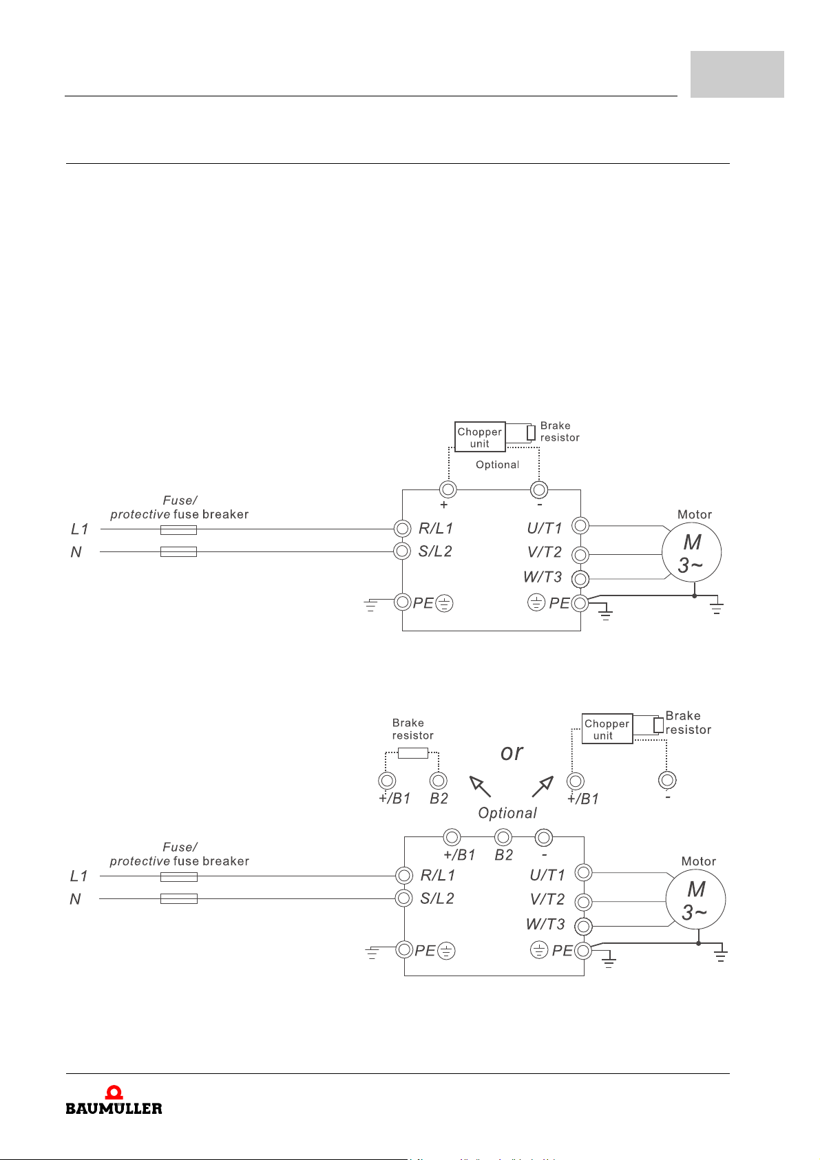
6.10.2 Connecting main terminals
m Frame 1 (BM1211, BM1212, BM1213, BM1412, BM1413, BM1414):
No built-in chopper unit:
Optional use of chopper unit and braking r esistor necessar y (refer to ZB.1. 2 Choppe r
units BM1-BTE– from page 119 and ZB.1.3 Dimensions and weights for br aking
resistors– from page 125).
m Frame 2 and 3 (BM1224, BM1225, BM1425, BM1426, BM1437, BM1438, BM1439):
Built-in chopper unit:
Optional connection of a suitable braking resisto r (se e ZB.1.3 Dimensions and
weights for braking resistors– from page 125) possible.
If the motor generates additional reg enerati on energy a further choppe r unit with br aking resistor can be connected.
m BM1211, BM1212, BM1213 (Frame 1)
Installation
6
Figure 26: Mains terminals connections 1
m BM1224, BM1225 (Frame 2)
Figure 27: Mains terminals connections 2
Manual b maXX® BM1000
Document No. 5.07003.06
55
of 172
Page 56
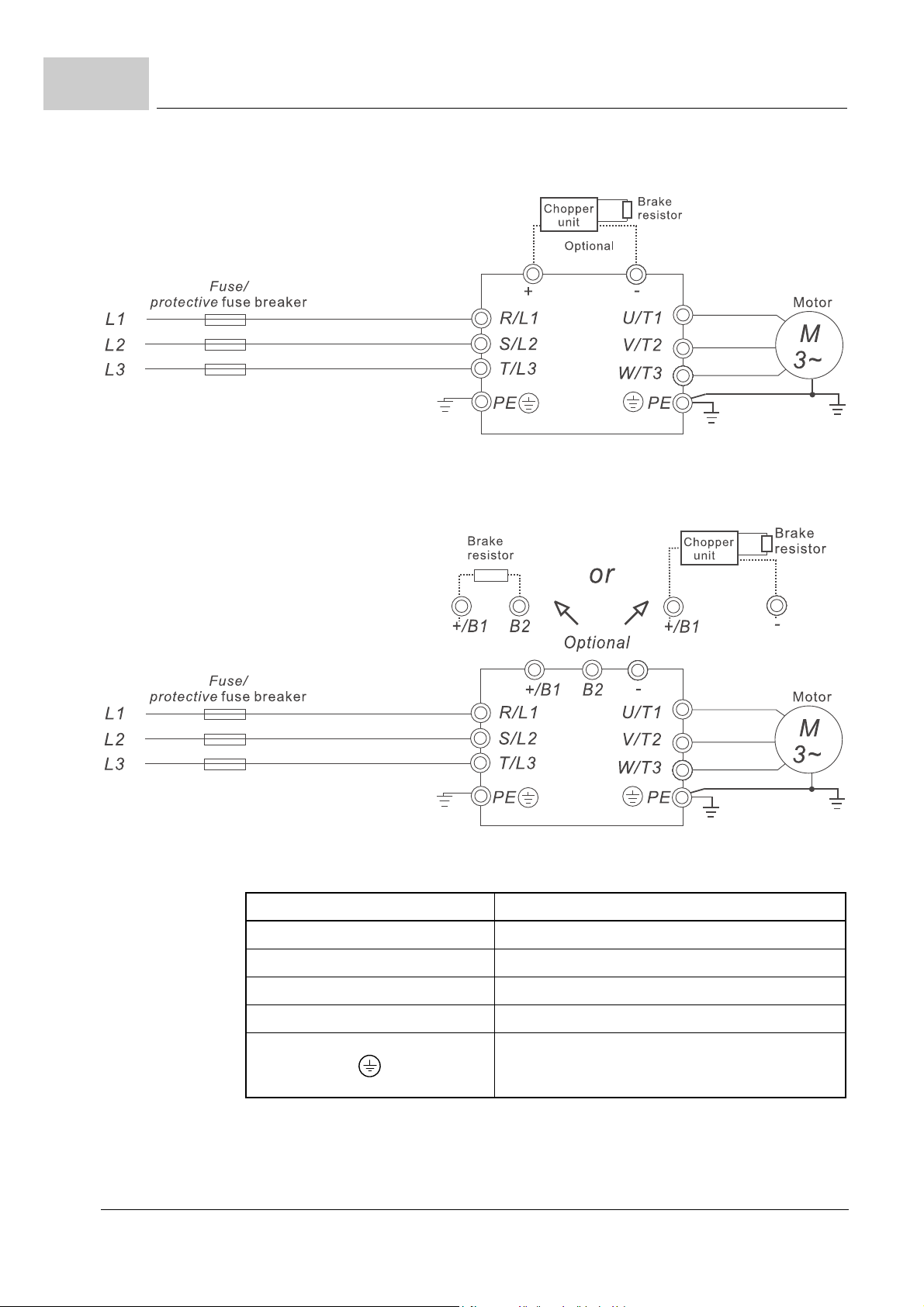
6.10
External connections
m BM1412, BM1413, BM1414 (Frame 1)
Figure 28: Main terminals connections 3
m BM1425, BM1426, BM1437, BM1438, BM1439 (Frame 2)
56
of 172
Figure 29: Main terminals connections 4
Terminal Symbol Explanation of Terminal Function
R/L1, S/L2, T/L3 Input terminals (1-phase/3-phase)
U/T1, V/T2, W/T3 Output terminals for connecting 3-phase motor
+/B1, B2 Connections for braking resistor (optional)
+/B1, - Connections for external chopper unit (optional)
Earth connection, please comply with local regulations.
Manual b maXX® BM1000
Document No. 5.07003.06 Baumüller Nürnberg GmbH
Page 57
6.10.3 Mains power terminals (R/L1, S/L2, T/L3)
Connect these terminals (R/L1, S/L2, T/L3) via a protective fuse breaker or earth leak-
age breaker to 3-phase mains power (some models to 1 -phase mains power) for circuit
protection. It is unnecessary to consider phase-sequence.
It is recommended to a dd a magnetic contactor in the powe r input wiring to cut off pow-
er quickly and reduce malfunction wh en ac tivating the protection function of b maXX
BM1000. Both ends of the magnetic contactor should have an R-C surge absorber.
Please make sure to fasten the screw of the main circuit terminals to preven t sparks
which is made by the loose screws due to vibration.
When using a GFCI (Ground Fault Circuit Interrupter) , select a current sensor with sen-
sitivity of 200 mA, and not less than 0.1-second detection time to avoid nuisance tripping.
Do NOT run/stop the b maXX® BM1000 by turning the power ON/OFF. Run/stop the
b maXX® BM1000 by RUN/STOP command via control terminals or keypad. If you still
need to run/stop the b
to do so only ONCE per hour.
Do NOT connect 3-phase models to a 1-phase power source.
maXX® BM1000 by turning power ON/OFF, it is recommended
Installation
6
®
NOTE
No T/L3 terminal on 1-phase models
6.10.4 Output terminals (U/T1, V/T2, W/T3)
The factory setting of the operation direction is forwar d running. The methods to control
the operation direction are: method 1, set by the communication parameters, method
2, control by the optional keypad.
When the b maXX® 1000 output terminals U/T1, V/T2, and W/T3 are connected to the
motor terminals U/T1, V/T2, and W/T3, respectively, the motor will rotate counterclock
wise (as viewed on the shaft end of the motor) when a forward operation command is
received. To permanently reverse the direction of motor rotation, switch over any of the
two motor leads.
DO NOT connect phase-compensation capacitors or surge absorbers at the output
terminals of the device.
With long motor cables, high capacitive switching current peaks can cause over-cur-
rent, high leakage current or lower current readout accuracy. To prevent this, the motor
cable should be less than 20 m for 3.7 kW models and below. And th e cable should be
less than 50 m for 5.5 kW models and above. For longer motor cables use an output
choke.
Use a well-insulated motor, suitable for inverter operation.
-
Manual b maXX® BM1000
Document No. 5.07003.06
57
of 172
Page 58
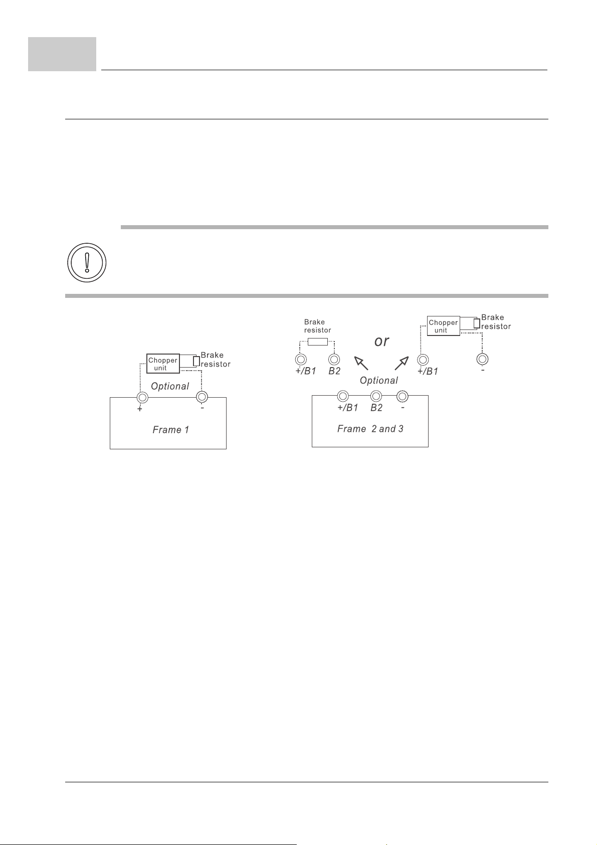
6.10
6.10.5 Terminals [+/B1, B2] for connecting chopper unit / braking resistor
External connections
Connect a braking resistor and/or chopper unit in applications with frequent decelera-
tion ramps, short deceleration time, too low braking torque or requiring increased b raking torque.
Connect the terminals [+, -] of the brake unit to the b maXX® 1000 terminals
[+/B1, -]. The length of wiring should be less than 5 m with twisted cable.
When not used, please leave the terminals [+/B1, -] open.
CAUTION
The following may occur, if you do not observe this caution information:
m Short-circuiting [B2] or [-] to [+/B1] can damage the b maXX® 1000.
Figure 30: Terminals braking resistor
m Frame 1 (BM1211, BM1212, BM1213, BM1412, BM1413, BM1414):
No built-in chopper unit:
Optional use of chopper unit and braking resistor necessary (refer to ZB.1.1 Select a
chopper unit /braking resistor– from page 118).
Please connect an external chopper uni t and brakin g resistor to the terminal [+, -], see
ZConnecting main terminals– from page 55.
m Frame 2 and 3 (BM1224, BM1225, BM1425, BM1426, BM1437, BM 1438, BM1439):
Built-in chopper unit:
Optional connection of a suitable braking resistor possible.
If the motor generates additional regeneration energy a further chopper un it with braking resistor can be connected (see ZB.1.1 Select a chopper unit /braking resistor–
from page 118).
Please connect the external chopper unit to the terminals [+/B1, B2], see ZConnecting
main terminals– from page 55.
58
of 172
Manual b maXX® BM1000
Document No. 5.07003.06 Baumüller Nürnberg GmbH
Page 59
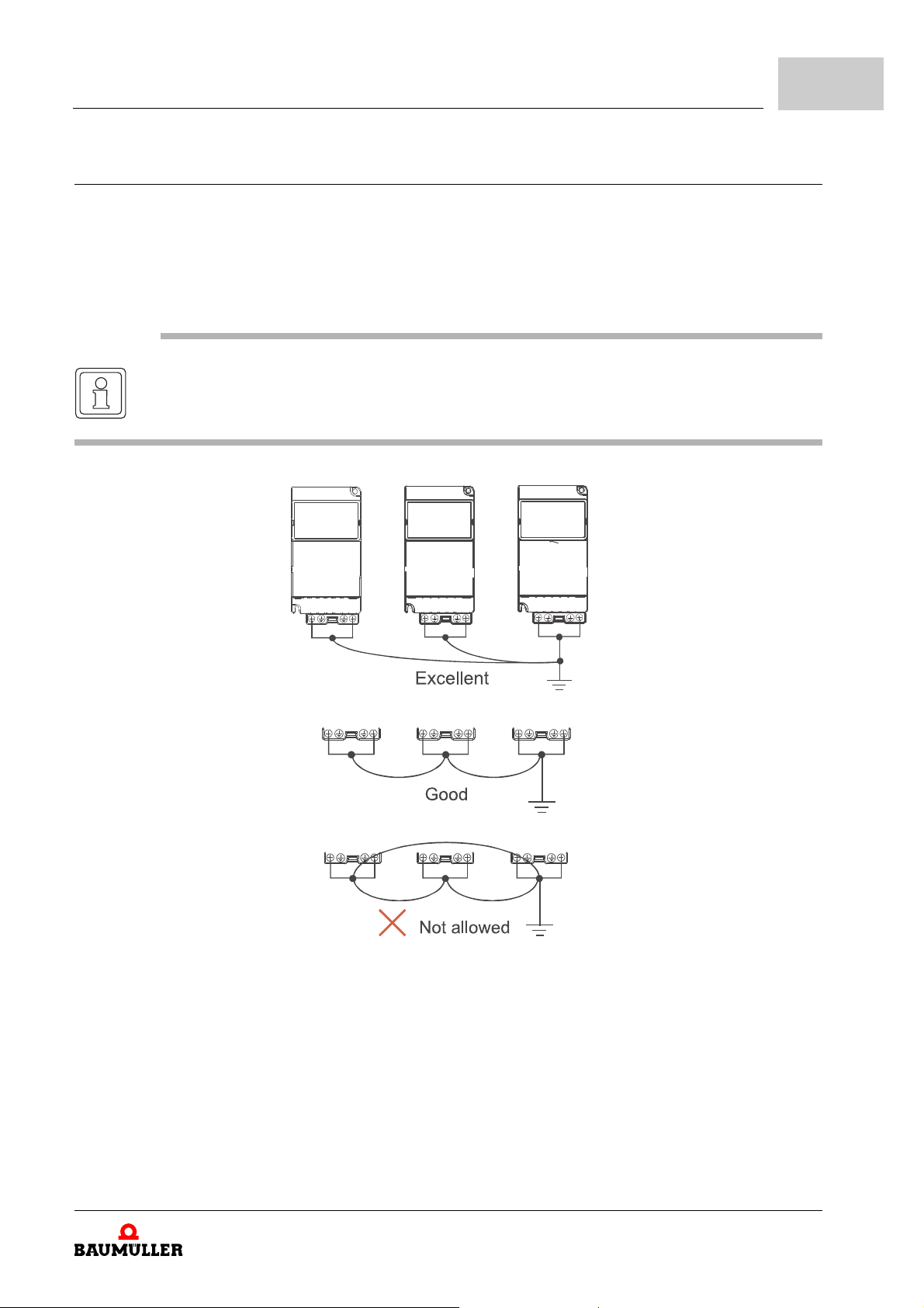
6.10.6 Grounding terminals
Make sure that the leads are connected correctly and the b maXX® 1000 is properly
grounded. (Ground resistance should not exceed 0.1Ω.)
Use ground leads that comply with local regulations and keep them as short as possi-
ble.
Multiple b maXX® 1000 units can be installed in one location. All the units should be
grounded directly to a common ground terminal, as shown in the figure below.
NOTE
Ensure there are no ground loops.
Installation
6
Figure 31: Connecting grounding terminals
Manual b maXX® BM1000
Document No. 5.07003.06
59
of 172
Page 60
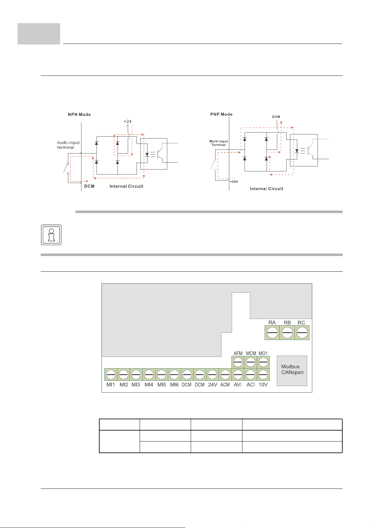
6.11
TERMINALS 2
T
ERMINALS 1
Control Terminals
6.11 Control Terminals
Circuit diagram for digital inputs (NPN current 16 mA.)
NOTE
Control signal wiring size: 18 AWG (0.75 mm2) with shielded wire.
6.11.1 Specification of control terminals
60
of 172
Figure 32: Position of control terminals
Frame Control terminals Torque Wire
1, 2, 3
Terminals 1 0.5 Nm 12-24 AWG (3.3-0.2mm²)
Terminals 2 0.2 Nm 16-24 AWG (1.3-0.2mm²)
Manual b maXX® BM1000
Document No. 5.07003.06 Baumüller Nürnberg GmbH
Page 61
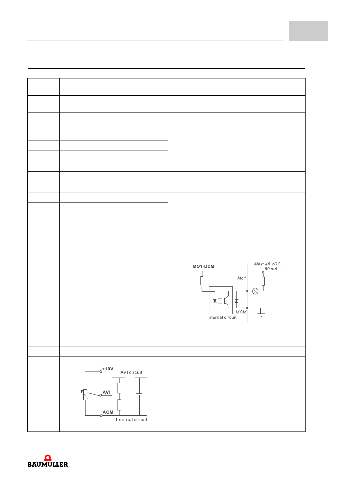
6.11.2 Terminal symbols and functions
Installation
6
Terminal
symbol
MI1 Forward-Stop command ON: Run in MI1 direction
MI2 Reverse-Stop command ON: Run in MI2 direction
MI3 Multi-function input 3 Refer to P1091 to P1094 for programming the multiMI4 Multi-function input 4
MI5 Multi-function input 5
MI6 Multi-function input 6 Fix value for pulse (controller) enable
+24V DC voltage source +24VDC, 20 mA used for PNP mode.
DCM Digital signal ground Ground for digital inputs and used for NPN mode.
RA Multi-function relay output (N.O.) a Resistive Load:
RB Multi-function relay output (N.C.) b
RC Multi-function relay ground
MO1 Mu lti- fu nct i on outpu t 1 (p ho to co up le r) Maximum 48 VDC, 50 mA
Terminal function Factory settings (NPN mode)
ON: connect to DCM
OFF: Stop accor ding to stop method
OFF: Stop accor ding to stop method
function Inputs.
ON: the activation current is 16mA.
OFF: leakage current tolerance is 10µA.
5A (N.O.) / 3A (N.C.) 240 V
5A (N.O.) / 3A (N.C.) 24 V
Inductive Load:
1.5A (N.O.) / 0.5A (N.C.) 240 V
1.5A (N.O.) / 0.5A (N.C.) 24 V
Refer to P1110 for programming
Refer to P1111 for programming
AC
DC
AC
DC
Figure 33: Multi-function output 1
MCM Multi-function output ground Ground for multi-function outputs
+10V Potentiometer power supply +10VDC 3 mA
AVI Analog voltage input
Figure 34: Analog voltage input
Impedance: 47 kΩ
Resolution: 10 bits
Range: 0 to 10 VDC =
0 to max. output frequency (P0033)
Selection: P0801, P0809, P1359
Set-up: P1128 to P1132
Manual b maXX® BM1000
Document No. 5.07003.06
61
of 172
Page 62
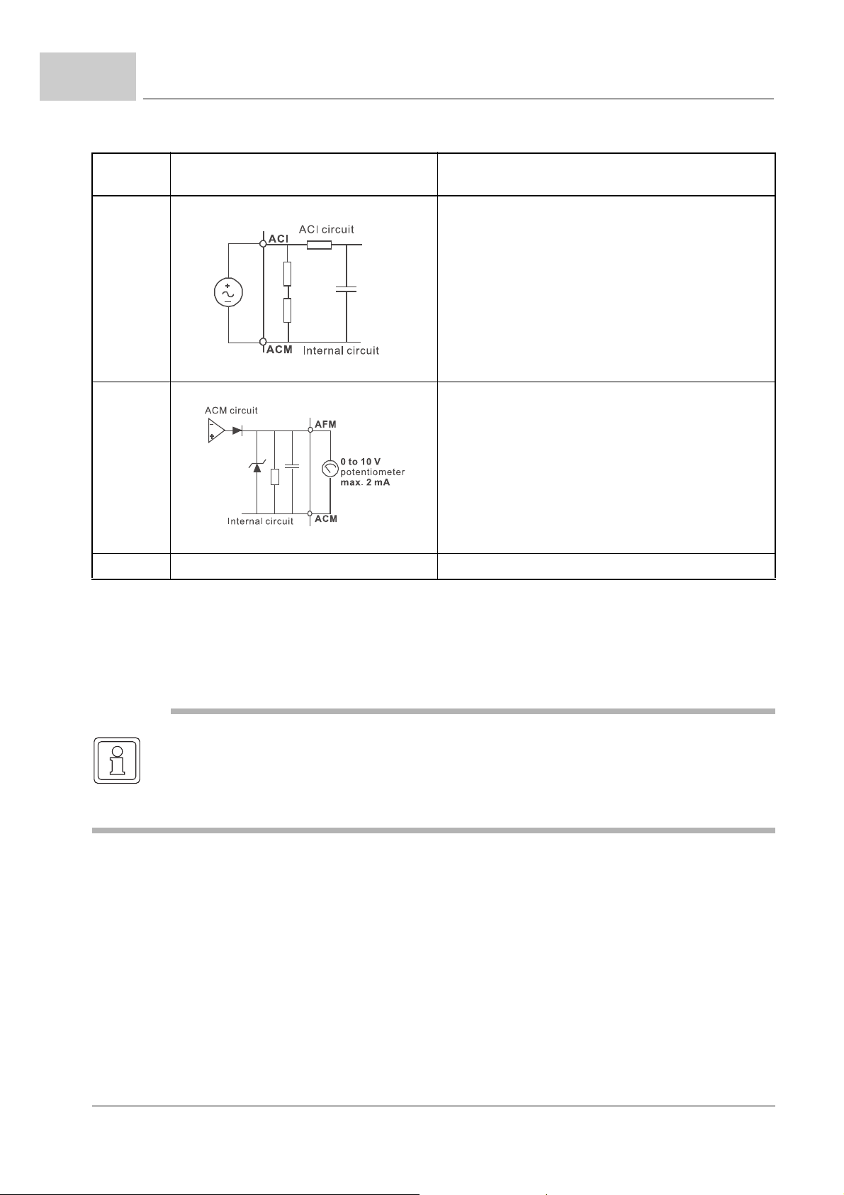
6.11
Control Terminals
Terminal
symbol
ACI Analog current input
AFM Analog output meter
ACM Analog control signal (ground) Ground for AVI, ACI, AFM
Te rm in al fu nct i on Factory settings (NPN mode)
ON: connect to DCM
Impedance: 250 Ω
Resolution: 10 bits
Range: 4 to 20 mA =
0 to max. output frequency (P0033)
Selection: P0801, P0809, P1359
Set-up: P1128 to P1132
Figure 35: Analog current input
0 to 10 V, 2 mA
Impedance: 20 kΩ
Output current 2 mA max.
Resolution: 8 bits
Range: 0 to 10 V
Function: P1162 and P1163
Figure 36: Analog output meter
DC
Keep control wiring as far away as possible fr om the power wiring and in se parate con-
duits to avoid interference. If necessary let them cross only at 90º angle.
The device control wiring should be pr operly installed and not touch any live powe r wir-
ing or terminals.
NOTE
If a filter is required for reducing EMI (Electro Magnetic Interference), install it as close as
possible to the device. EMI can also be reduced by lowering the carrier frequency.
When using a GFCI (Ground Fault Circuit Interrupter), select a current sensor with sensi-
tivity of 200 mA, and not less than 0.1-second detection time to avoid noise tripping.
62
of 172
Manual b maXX® BM1000
Document No. 5.07003.06 Baumüller Nürnberg GmbH
Page 63
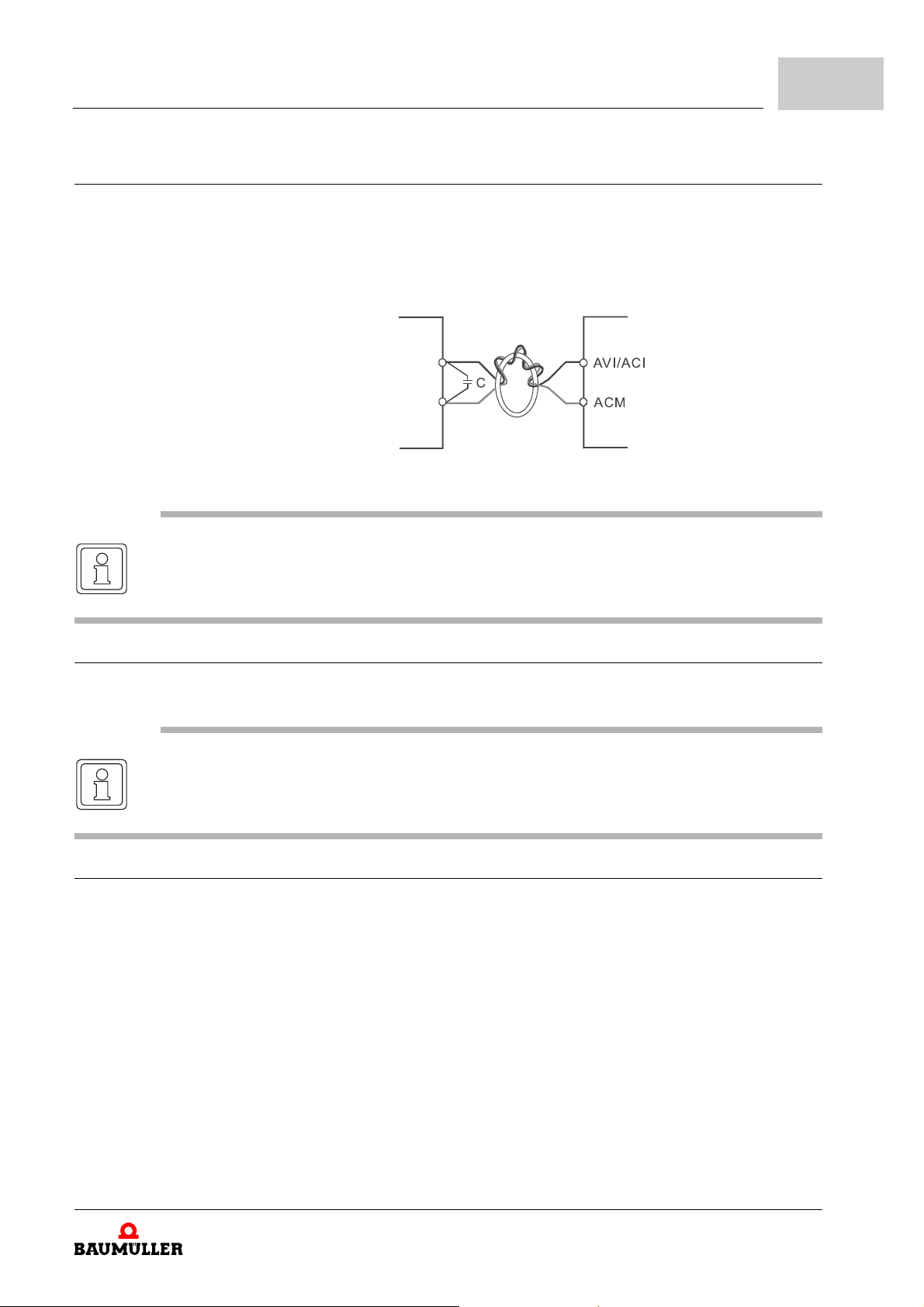
6.11.3 Analog input terminals (AVI, ACI, ACM)
ferrite core
Analog input signals are easily affected by external noise. Use shielded wiring and
keep it as short as possible (< 20 m) with proper grounding. If the noise is inductive,
connecting the shield to terminal ACM can bring improvement.
If the analog input signals are affected by noise from th e device, please connect a ca-
pacitor (0.1 F and above) and ferrite core as indicated in the following diagrams:
Figure 37: Analog input terminals
NOTE
Wind each wires 3 times or more around the core
Installation
6
6.11.4 Multi-function-i n pu t s (M I1 to MI 6, DCM)
When using contacts or switches to control the digital inputs, please use high quality
components to avoid contact bounce.
NOTE
The multi-function inputs MI1 and MI2 are used for operation commands (e.g. STOP, RUN,
FWD, REV) only.
6.11.5 Multi-function output (MO1, MCM)
Make sure to connect the digital outputs to the right polarity, see wiring di agrams.
When connecting a relay to the digital outputs, connect a sur ge absorber or flyback di -
ode across the coil and check the polarity.
Manual b maXX® BM1000
Document No. 5.07003.06
63
of 172
Page 64
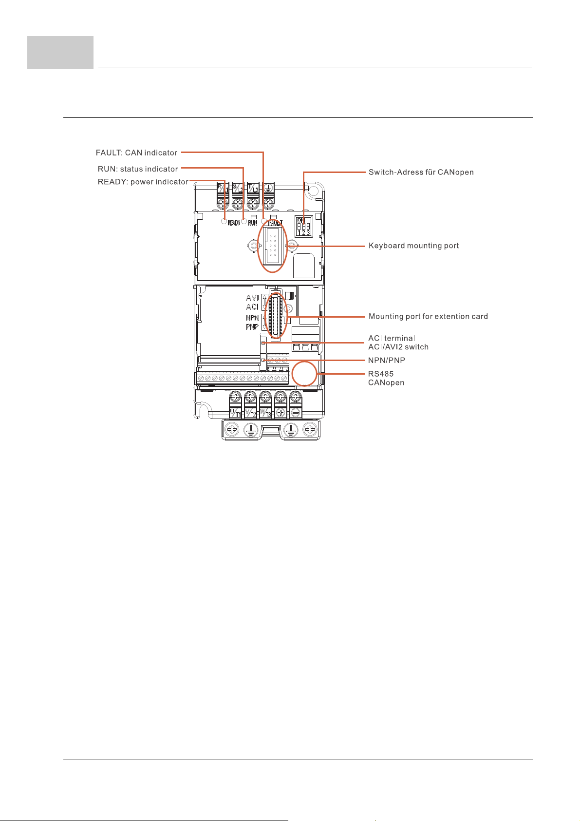
6.12
External parts
6.12 External parts
Figure 38: External parts
64
of 172
Manual b maXX® BM1000
Document No. 5.07003.06 Baumüller Nürnberg GmbH
Page 65
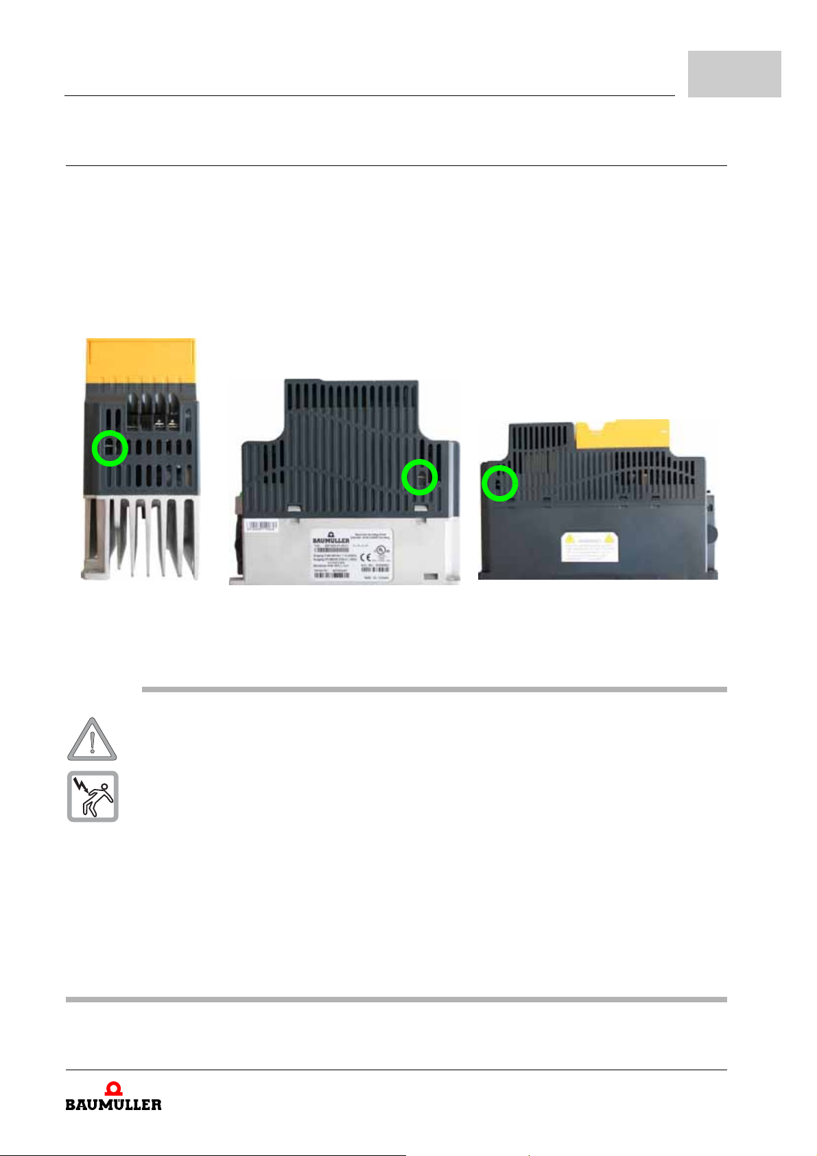
6.13 RFI jumper
Installation
Main power isolated from earth:
If the device is supplied from an isolated po wer (IT power), the RF I jumper must be cut
off. Then the RFI capacities (filter capacitors) will be disconnected from ground to prevent
circuit damage (according to IEC 61800-3) and reduce earth leakag e current. Refer to the
following figures for the position of RFI jumper.
6
Frame 1
(on the top)
WARNING
The following may occur, if you disregard these safety notes:
m serious personal injury m death
The danger is: electricity. Parts, which are under tension are perilous.
After applying power to the device, do not cut off th e R FI jump er. T herefo re, p lease make
The gap discharge may occur when the transient voltage is higher than 1,000V. Besides,
Do NOT cut the RFI jumper when main power is connected to earth.
The RFI jumper cannot be cut when high voltage tests are performed. The mains power
To prevent drive damage, the RFI jumper con nected to ground shall be cut off if the device
Frame 2
(at the right side)
sure that main power has been switched off before cutting the RFI jumper.
electro-magnetic compatibility of the device will be lower after cutting the RFI jumper.
and motor must be separated if high voltag e test is performed and the leaka ge currents are
too high.
is installed on an ungrounded power system or a high resistance-grounded (over 30 Ω)
power system or a corner grounded TN system.
Frame 3
(at the left side)
Manual b maXX® BM1000
Document No. 5.07003.06
65
of 172
Page 66
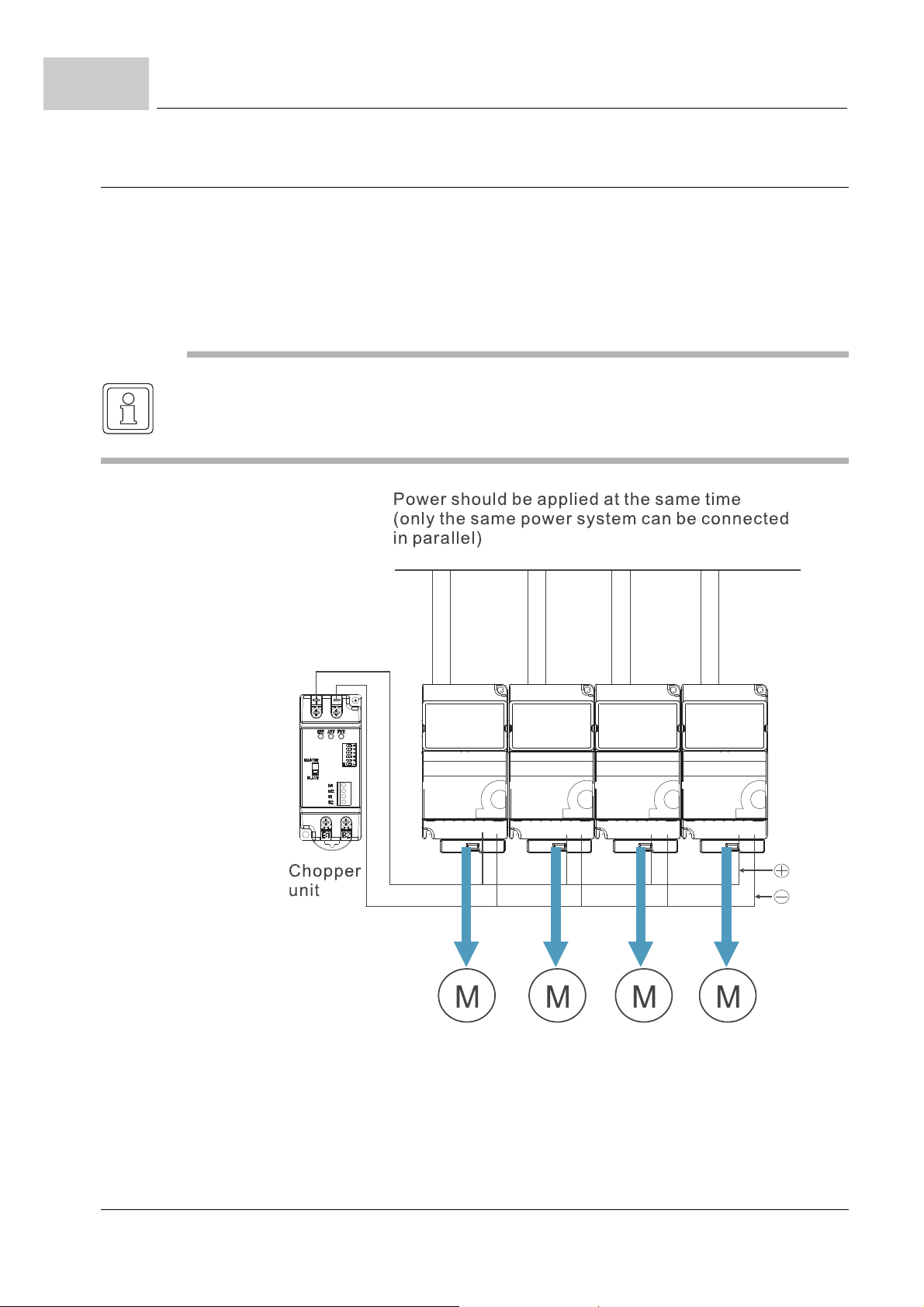
6.14
Connect the DC link of the devices in parallel
6.14 Connect the DC link of the devices in parallel
m The devices can absorb mutual voltage that generated to DC link when deceleration
m Enhance brake function and stabilize the voltage of the DC link
m The brake module can be added to enhance brake function after connecting in par allel
m Only the same power system can be connected in parallel
m It is recommended to connect 5 devices in parallel (no limit in power)
NOTE
Power should be applied at the same time (only the same powe r system can be connected in
parallel)
66
of 172
Figure 39: DC link of the devices in parallel
Manual b maXX® BM1000
Document No. 5.07003.06 Baumüller Nürnberg GmbH
Page 67
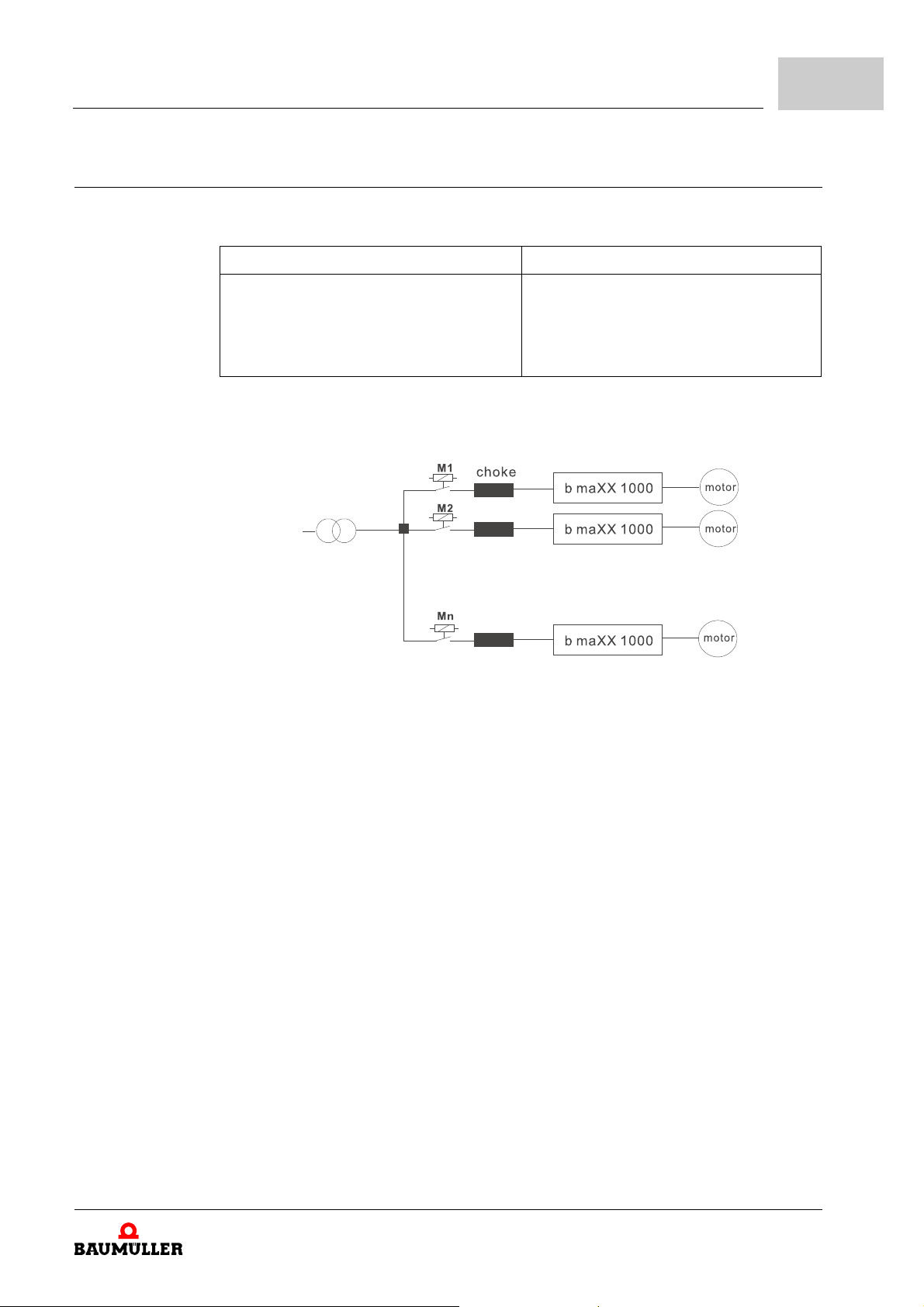
6.15 Applications for mains chokes
Connected in input circuit
Application 1 Question
Installation
6
When more than one device is connected
to the same mains power , and one of them
is ON during operation.
Correct wiring
Figure 40: Application 1 mains choke
When applying power to one of the
devices, the charge current of the capaci
tors may cause voltage dip. The device
may be damaged when overcurrent
occurs during operation.
-
Manual b maXX® BM1000
Document No. 5.07003.06
67
of 172
Page 68
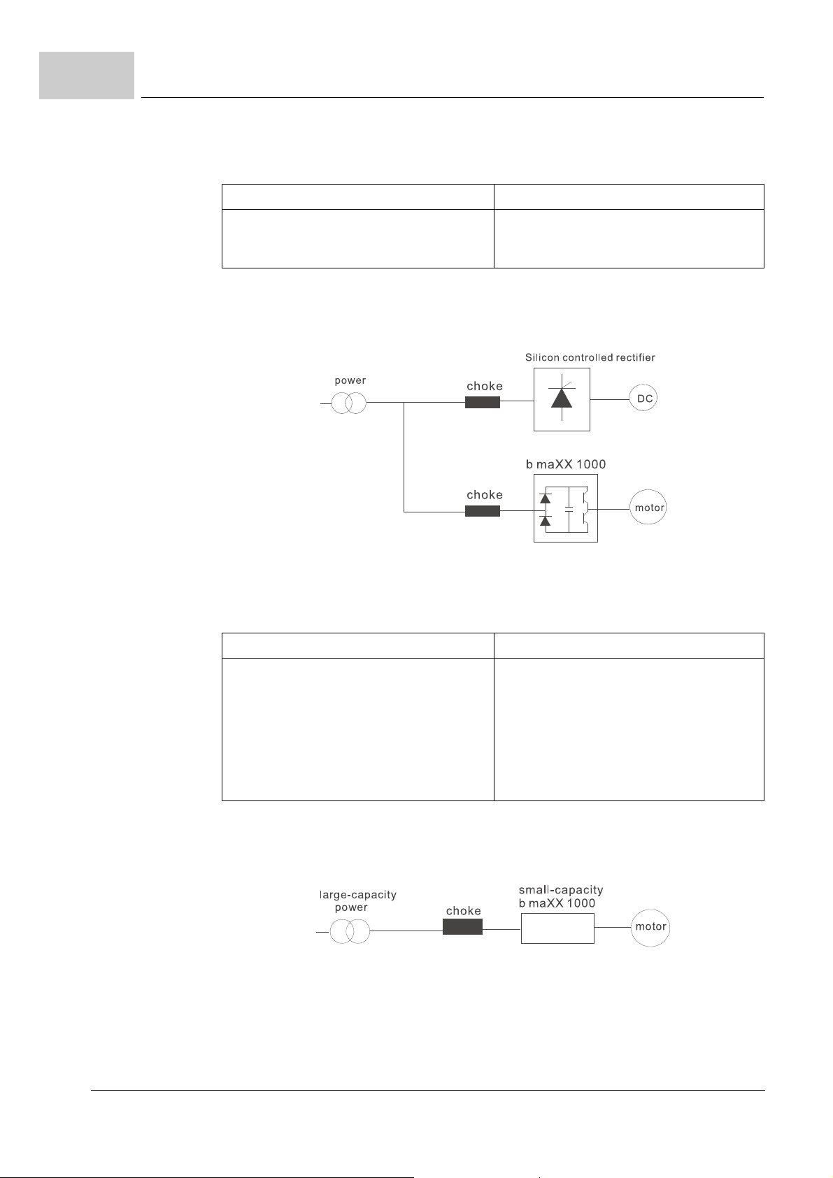
6.15
Applications for mains chokes
Application 2 Question
Silicon rectifier and device are connected
to the same power.
Correct wiring
Figure 41: Application 2 mains choke
Switching spikes will be generated when
the silicon rectifier switches on/off. These
spikes may damage the mains circuit.
Application 3 Question
Used to improve the input power factor, to
reduce harmonics and provide protection
from AC line disturbances (surges, switch
ing spikes, short interruptions, etc.). The
chokes should be installed when the
power supply capacity is 500 kVA or more
and exceeds 6 times the inverter capacity,
or the mains wiring distance ≤ 10
Correct wiring
Figure 42: Application 3 mains choke
m.
When the mains power capacity is too
large, line impedance will be small and the
charge current will be too high. This may
damage b
higher rectifier temperature.
maXX® BM1000 drive due to
68
of 172
Manual b maXX® BM1000
Document No. 5.07003.06 Baumüller Nürnberg GmbH
Page 69
In this chapter we describe, how the device works during operation and how you handle
the device during operation.
7.1 Safety instructions
h Refer to the safety instructions from the chapter ZFundamental safety instructions–
from page 9.
CAUTION
The following may occur, if you disregard these safety notes:
m Property damage
The danger is: Environmental conditions, that do not refer to the demands.
Assure, that the environmental conditions are referred to during operation (see ZD.1 Re-
quired environmental conditions– on page 140).
7OPERATION
WARNING
The following may occur, if you disregard these safety notes:
m serious personal injury m death
The danger is: electricity. The control cabinet, in which the device is built in, shall protect
against contacts with parts, which are under voltage.
Assure, that during operation all doors of the control cabinet are closed.
Assure, that during operation all safety devices work.
Manual b maXX® BM1000
Document No. 5.07003.06
of 172
69
Page 70
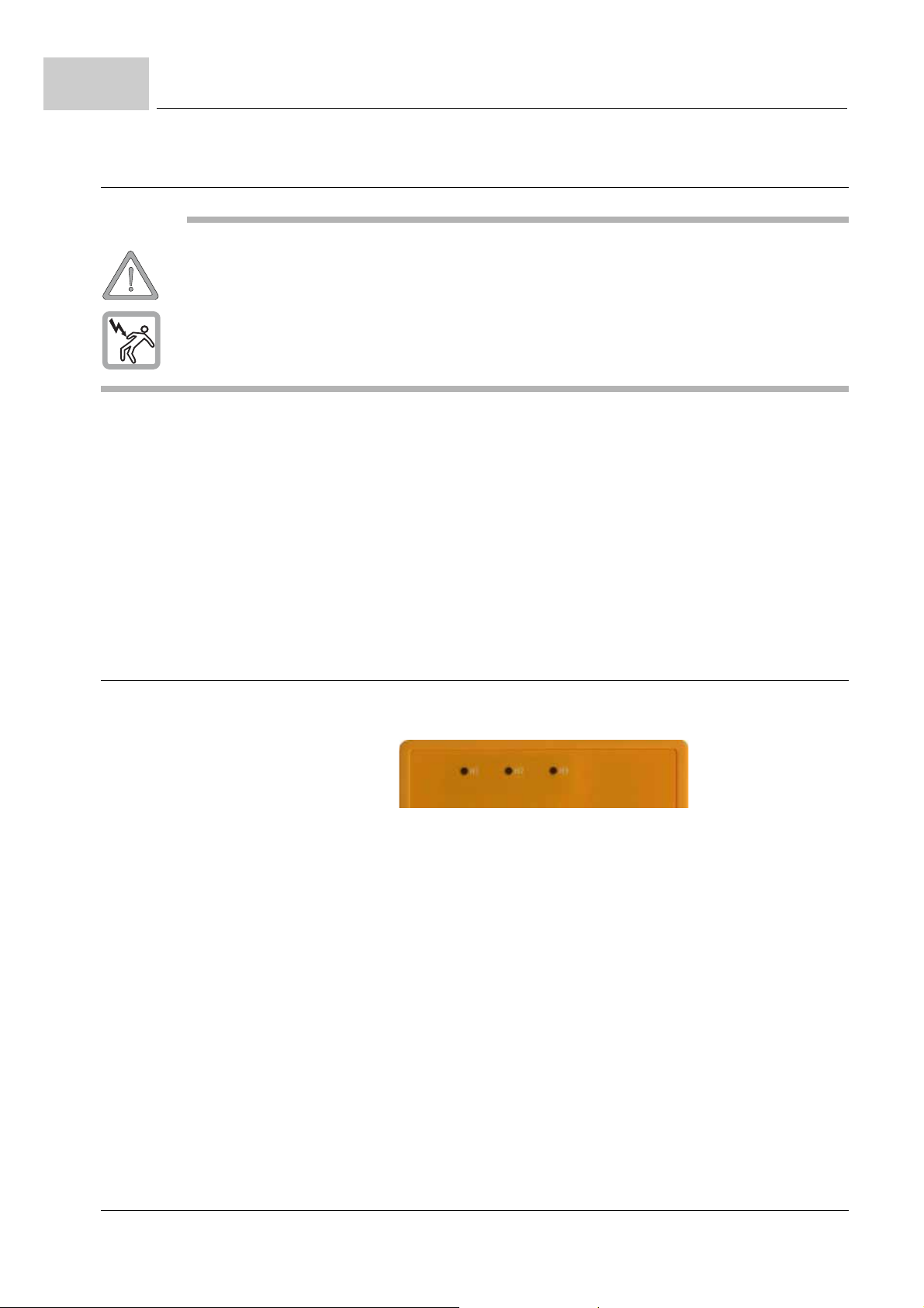
7.2
H1 H2 H3
Requirements to the executing personnel
7.2 Requirements to the executing personnel
WARNING
The following may occur, if you disregard these safety notes:
m serious personal injury m death
The danger is: electricity.When operating with this electrical un it, inevitably certain pa rts of
this unit are under dangerous voltage.
Assure, that only qualified personnel work on this unit.
At each case qualified personnel are persons, who are authorized by the responsible persons, to execute necessary actions and who recognize the possible danger s and who are
able to avoid these dangers. They have had the training, the experience, they were given
instructions as well as knowledge about the relevant standards and instructions, they
have knowledge of the accident prevention regulations and of the operating environ
ments. The required qualifications for the work with this unit are for example:
m Education or instruction or to have the authorization to put into operation, ground and
label circuits and devices according to the standards of safety engineering.
m Training or instruction due to the standards of the safety engineering in maintenance
and use of appropriate safety equipm en t.
-
7.3 LEDs
There are three LEDs on the front of the b maXX® when using no optional digital keypad:
H1: READY
It will light up after applying power.
The light won’t be off until the capacitors are discharged to safe voltage levels after
power off.
H2: b maXX® drive status
It will light up green, when the drive is in status operation enabled.
It will light up red, when the drive is in error status.
H3: CANopen status
It will light up green, when the CANopen is in operation.
It will light up red, when CANopen is in status bus off.
70
of 172
Manual b maXX® BM1000
Document No. 5.07003.06 Baumüller Nürnberg GmbH
Page 71
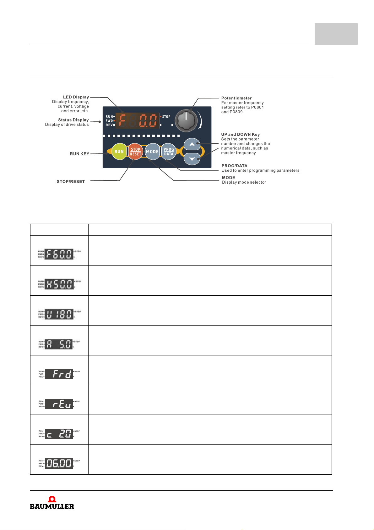
7.4 Digital keypad (option)
Figure 43: Digital keypad
Operation
7
Display Message Description
Displays the master frequency.
Displays the actual output frequency at terminals U/T1, V/T2, and W/T3.
User defined unit (where U = F x P0038)
Displays the output current at terminals U/T1, V/T2, and W/T3.
Displays the forward run status.
Displays the reverse run status.
The counter value (C).
Displays the selected parameter.
Manual b maXX® BM1000
Document No. 5.07003.06
71
of 172
Page 72
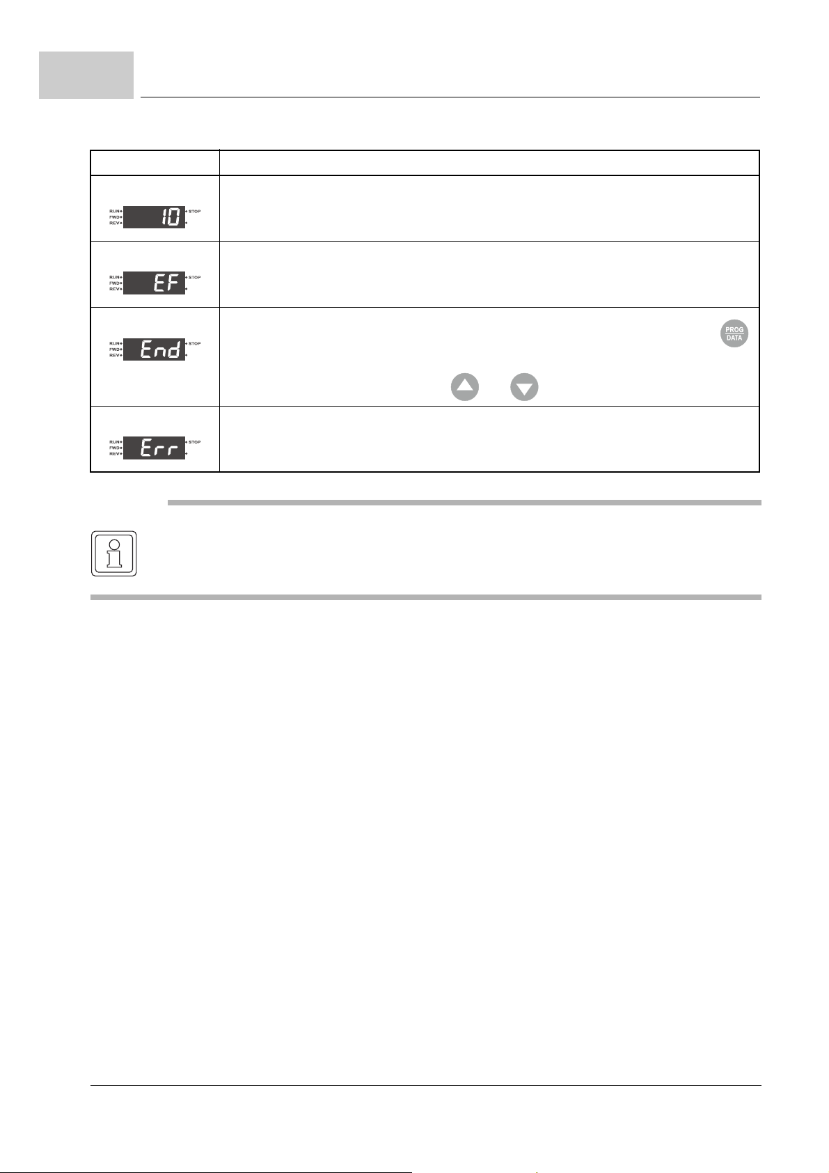
7.4
Digital keypad (option)
Display Message Description
Displays the actual stored value of the selected parameter.
External Fault.
Display „End“ for approximately 1 second if input has been accepted by pr essing
key. After a parameter value has been set, the new value is automatically stored in
memory. To modify an entry, use the
Display „Err“, if the input is invalid.
NOTE
When the setting exceeds 99.99 for those numbers with 2 decimals (i.e. unit is 0.01), it will
only display 1 decimal due to 4-digital display.
and keys.
72
of 172
Manual b maXX® BM1000
Document No. 5.07003.06 Baumüller Nürnberg GmbH
Page 73
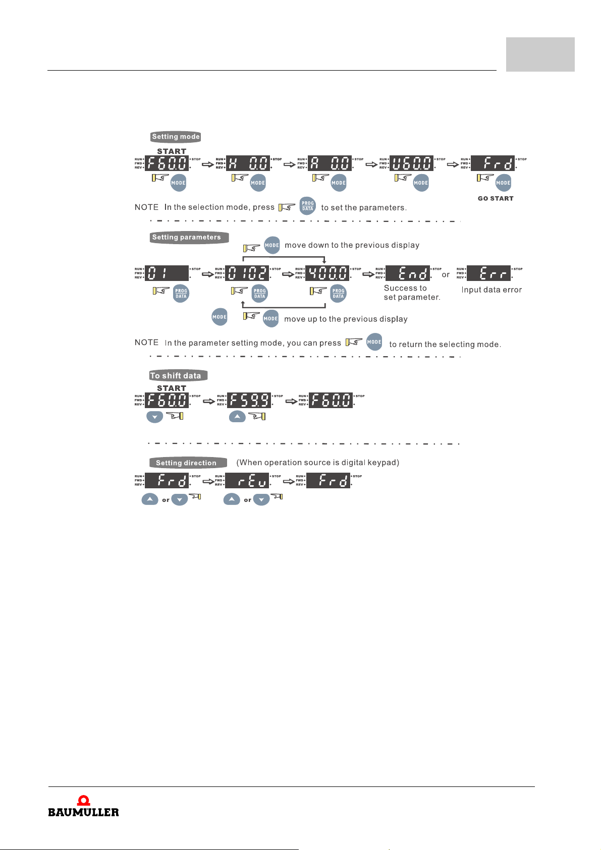
m How to operate the digital keypad
Operation
7
Figure 44: Keypad operation
Manual b maXX® BM1000
Document No. 5.07003.06
73
of 172
Page 74
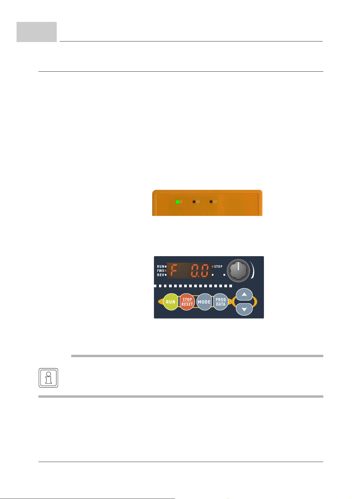
7.5
H1 H2 H3
Preparations before commissioning
7.5 Preparations before commissioning
Carefully check the following items before proceeding.
Make sure that the wiring is correct. In particular, check that the output termin als U/T1,
V/T2, W/T3 are NOT connected to power and that the drive is well grounded.
Verify that there are no short-circuits between terminals and from terminals to ground
or mains power.
Check for loose terminals, connectors or screws.
Verify that no other equipment is connected to the motor.
Make sure that all switches are OFF before applying power to ensure that the device
doesn't start running and there is no abnormal operation after applying power.
Make sure that the front cover is correctly installed before applying power.
Do NOT operate the device with humid hands.
Check the following items after applying power: The display without digital keypad
should be as follows.
When power is applied. LED „H1“ should light up
Figure 45: Device ready without digital keypad
The display with digital keypad should light up as follows (normal status with no error)
When power is ON, it will is displayed „F0.0“ and LED „STOP“
and „FWD“ should light up
Figure 46: Device ready digital keypad
NOTE
If the drive has a built-in fan, it should run. Th e factory set ting of Fan con trol P0024 = 0 (fan
always on).
74
of 172
Manual b maXX® BM1000
Document No. 5.07003.06 Baumüller Nürnberg GmbH
Page 75
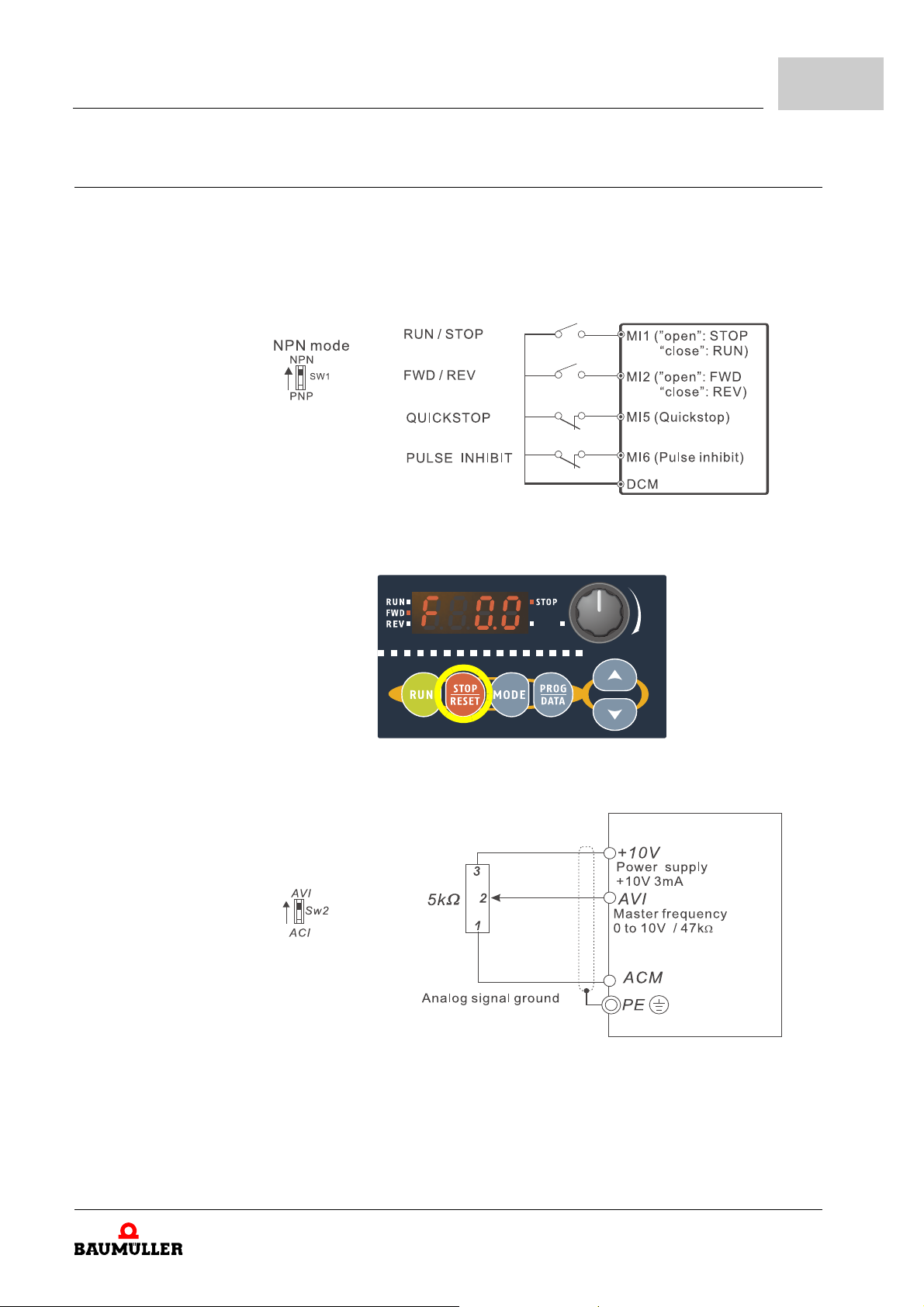
7.6 Commissioning example
m Source of first command
Operation
7
Required
functionality
RUN / STOP from multi-function input MI1
FWD (forward running)
REV (reverse running) from multi-function input MI2
Additional STOP from digital keypad
m First master frequency from analog voltage input AVI
Manual b maXX® BM1000
Document No. 5.07003.06
75
of 172
Page 76
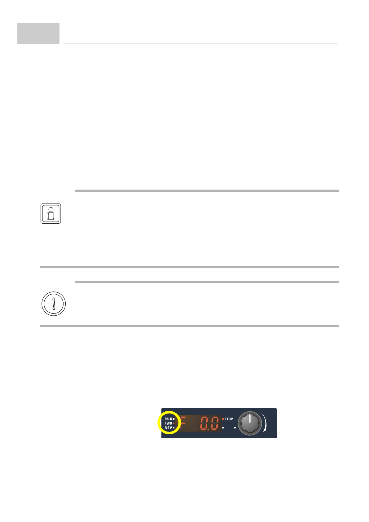
7.6
Commissioning example
Required
parameter
settings
Execute the autotuning function
NOTE
m Stop running immediately if any fault occurs and refer to the troubles hooting guide for solv-
m Do NOT touch output terminals R/L1, S/L2, T/L3 when power is still applied to U/T1, V/T2,
m To avoid damage to components, do not touch them or the circuit boards with metal o bjects
Operation of keypad see ZDigital keypad (option)– from page 71.
Reset parameter to factory setting P0310 ⇒ 9
Source of first operation command P0802 ⇒ 1
RUN/STOP from multi-function input MI1
FWD/REV from multi-function input MI2 P1090 ⇒ 1
Source of first master frequency P0801 ⇒ 1
The autotuning function sequence is necessary for a correct operation of the motor!
The autotuning function must be executed without motor load.
ing the problem.
W/T3 even when the device has stopped. The DC-link capacitors may still be charged to
hazardous voltage levels, even if the power has been turned off.
or your bare hands.
CAUTION
The motor will rotate!
Operation mode set value P1000 ⇒ 249
Autotuning with running motor (withou t load ) P0850 ⇒ 2
After finishing autotuning function parameter P0850 is set to 0.
The autotuning function is completed when LED RUN is OFF and LED STOP is ON.
76
of 172
Manual b maXX® BM1000
Document No. 5.07003.06 Baumüller Nürnberg GmbH
Page 77
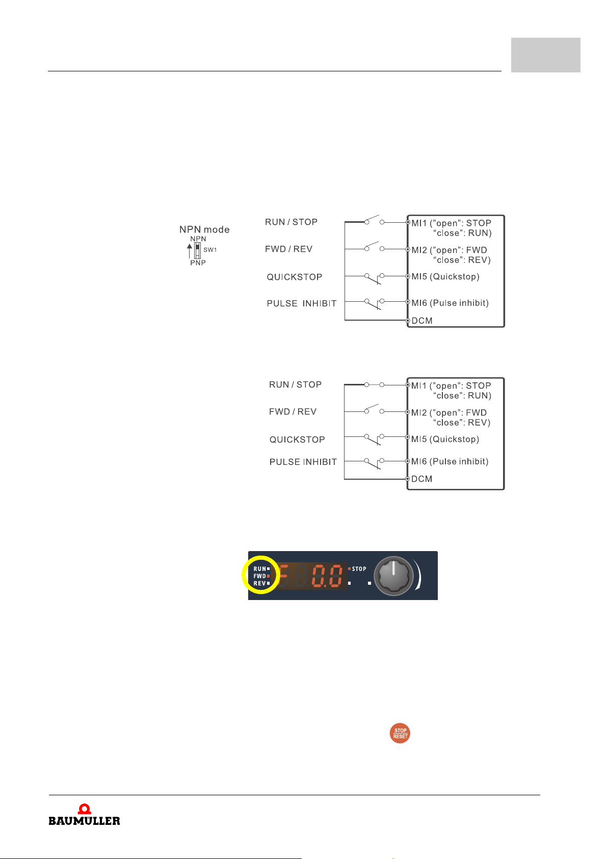
Operation
Operation mode set value P1000 ⇒ 2
(speed setting 1)
START from multi-function input MI1
1st step (close Quickstop)
7
Test of
functionality
2nd step (close RUN/STOP)
⇒ LED RUN = ON
⇒ LED STOP = OFF
START from multi-function input MI1
LED RUN or H1 = ON
LED STOP or H2 = OFF
Control the motor speed from analog voltage input AVI1.
Control the motor speed direction from multi-function input MI2.
And if you want to decelerate to stop, please press key.
Manual b maXX® BM1000
Document No. 5.07003.06
77
of 172
Page 78

7.7
Maintenance
7.7 Maintenance
Maintenance is first of all the monitoring of the environmental conditions. With accordant
projection of your installation you can execute the monitoring of the environmental condi
tions in the running operation and don’t have to interrupt the operation for the maintenance.
Additional data is available in ZMaintenance– from page 99.
-
78
of 172
Manual b maXX® BM1000
Document No. 5.07003.06 Baumüller Nürnberg GmbH
Page 79

8ERROR DETECTION AND TROUBLE-
In this chapter the error messages of the device are described: Error- and warning messages,
their meanings and how you can react.
8.1 Safety instructions
h Refer to ZFundamental safety instructions– from page 9.
8.2 Requirements to the executing personnel
The personnel, who works with the b maXX® device, must be introduced in the safety instructions and in the operation of the device and must be familiar with the accurate operating of the
device. Especially the reaction to failure indications and -conditions requires special knowledge,
which the operator must have.
8.3 Error information
SHOOTING
The b maxx® 1000 has a comprehensive fault diagnostic system that includes several d ifferent
alarms and fault messages. Once a fault is detected, the correspond ing protective functions will
be activated. The following faults are displayed as shown on the device digital key pad dis play.
The five most recent faults can be read from the digital keypad or communication.
NOTE
Wait 5 seconds after a fault has been cleared before performing reset via keypad of input terminal.
Manual b maXX® BM1000
Document No. 5.07003.06
79
of 172
Page 80

8.3
8.3.1 Fault code information
Error information
Fault
code
0003
0021
hex
hex
Fault
name
oc Over current
cPtE
cc02
cc04
to
cc08
Fault description Error
Abnormal increase in current.
CAN error P0296
reaction
PWM
inhibit
Corrective actions
m Check if motor power corresponds with
the device output power.
m Check the wiring connections to U/T1, V/
T2, W/T3 for possible short circuits.
m Check the wiring connections between
the device and motor for possible short
circuits, also to ground.
m Check for loose contacts between device
and motor.
m Increase the acceleration time.
m Check for possible excessive loading
conditions at the motor.
m If there are still any abnormal conditions
when operating the device after a shortcircuit is removed and the other points
above are checked, it should be sent
back to manufacturer.
m cPtE: initialization error
m cc02: Node Guarding or
Heartbeat error
m cc04: no CAN communication
between slave and master
m cc05: hardware failure or
no CANopen hardware
available on processing unit
m cc06: no CANopen software available
on processing unit
m cc07: an update of CANopen
is necessary
m cc08: hardware error
0030
0035
0050
80
of 172
AnCd Error in analog option
hex
AoFF Analog option card
hex
UbCd
hex
PE10
card
break off error
Communication error
USB (CME-USB-01) or
IO COM1 communica
tion time out
Manual b maXX® BM1000
Document No. 5.07003.06 Baumüller Nürnberg GmbH
P1007
PWM
inhibit
P0868
-
m Check or change analog option card
m Check or change analog option card
m Check or change analog option card
Page 81

Error detection and troubleshooting
8
Fault
code
0052
0054
Fault
name
hex
hex
ov Over voltage
GFF Ground fault PWM
Fault description Error
The DC link voltage has
exceeded its maximum
allowable value.
reaction
PWM
inhibit
inhibit
Corrective actions
m Check if the input voltage falls within the
rated device input voltage range.
m Check for possible voltage transients.
m DC link over-voltage may also be caused
by motor regeneration. Either increase
the deceleration time or add an optional
braking resistor (and brake unit).
m Check whether the required braking pow-
er is within the specified limits.
When (one of) the output terminal(s) is
grounded, short circuit current is more than
50
% of b maXX® rated current, the drive
power module may be damaged.
NOTE: The short circuit protection is provid-
ed for b maXX® drive protection, not for
protection of the user.
m Check whether the IGBT power module
is damaged.
m Check for possible poor insulation at the
output line.
0062
0063
0070
00A0
PtC1 Motor overheat protec-
hex
hex
hex
hex
oL1 Overload 1
PGEr Communication error
cE10 Communication error
tion
I²t > 100 %
PG card (option card)
modbus
P0119
PWM
inhibit
P1077
P0862
m Check if the motor is overheated
m Check P0117 to P0122 settings
m Check for possible motor overload.
m Check electronic thermal overload set-
ting.
m Use a higher power motor.
m Reduce the current level so that the drive
output current does not exceed the value
set by the Motor rated current P0054.
m Check or change PG option card
m Check the RS485 connection between
the b
maXX® drive and RS485 master
for loose wires and wiring to correct pins.
m Check if the communication protocol, ad-
dress, transmission speed, etc. are properly set.
m Use the correct checksum calculation.
Manual b maXX® BM1000
Document No. 5.07003.06
81
of 172
Page 82

8.3
Error information
Fault
code
00A1
00B0
00B2
Fault
Fault description Error
name
cP10 Communication time-
hex
out error on the control
board or power board
hex
cF10
EEPROM error P1007
cF11
cF20
cF21
Ecnt Checksum error in
hex
EEPROM
reaction
PWM
inhibit
PWM
inhibit
Corrective actions
m Press RESET key to set all parameters to
factory setting
m Return the b maXX® to the factory
m cF10,cF11:
internal EEPROM can not be programmed (return the b maXX® to the factory)
m cF20,cF21:
internal EEPROM can not be read (set all
parameters to factory setting or return the
b
maXX® to the factory)
m The parameter (P0077, P0110, P0811,
P0812, P0850, P1172, P1173, P1176,
P1177, P1180, P1181, P1182, P1183,
P1184, P1361, P1362, P1363, P1359)
writing to the EEPROM by power off was
not completed.
0500
0501
0502
hex
hex
hex
oH1 IGBT Overheating PWM
inhibit
Lv Low voltage
P0297
The device detects that
the DC link voltage has
fallen below its minimum
value.
PHL Phase loss PWM
inhibit
m Ensure that the ambient temperature is
within the specified temperature range.
m Make sure that the ventilation holes are
not obstructed.
m Remove any foreign objects from the
heatsink and check for possible dirty heat
sink fins.
m Check the fan and clean it.
m Provide enough spacing for adequate
ventilation.
m Check whether the input voltage falls
within the device rated input voltage
range.
m Check for abnormal load in motor.
m Check for correct wiring of input power
(for 3-phase models) without phase loss.
m Check input phase wiring for loose con-
tacts
0503
82
of 172
codE Password invali d P1007
hex
Manual b maXX® BM1000
Document No. 5.07003.06 Baumüller Nürnberg GmbH
m Return the b maXX® to the factory
Page 83
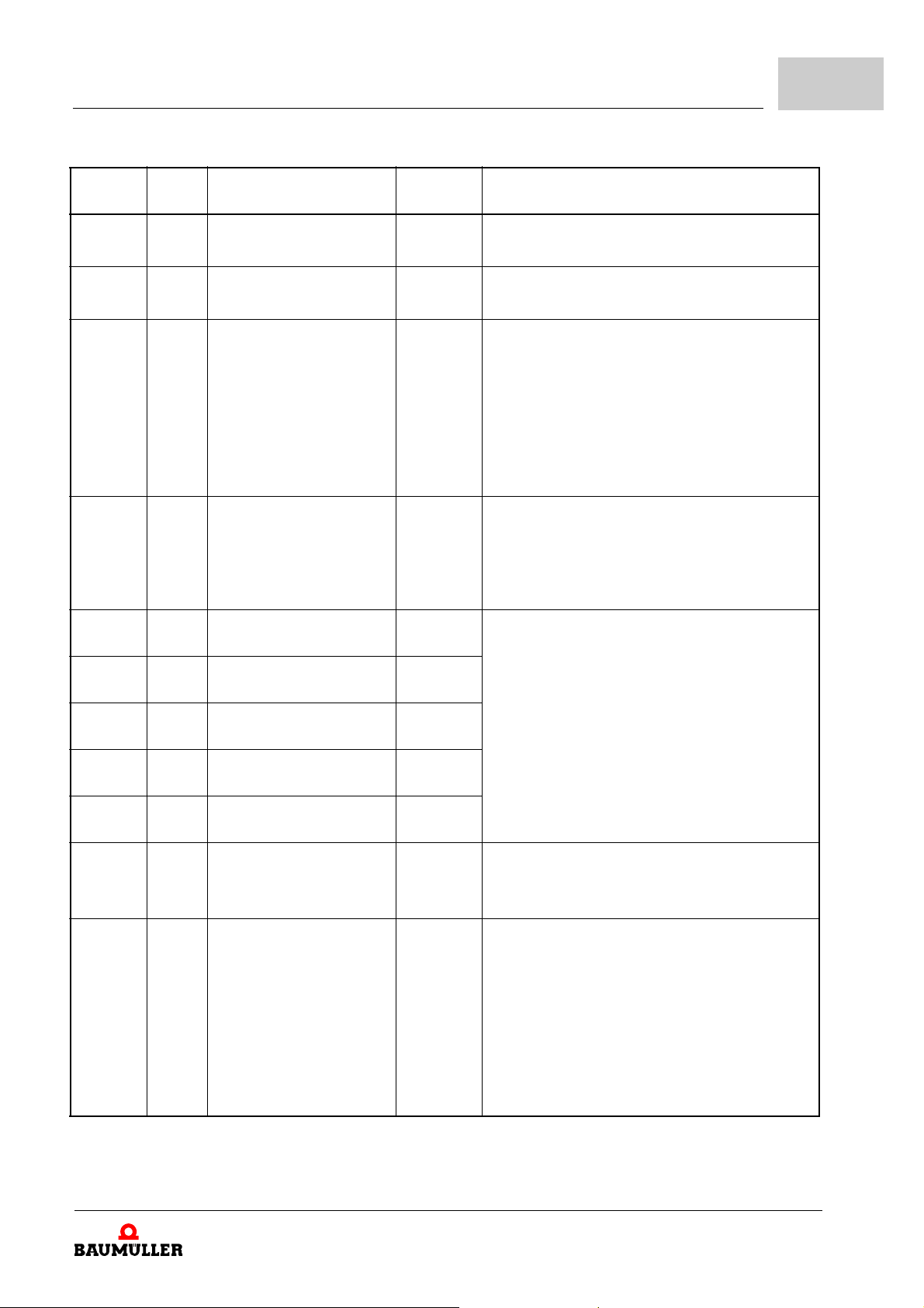
Error detection and troubleshooting
8
Fault
code
0505
0506
0507
0509
050A
Fault
name
cF34 Temperatu re se n sor
hex
Aerr Analog signa l error P0806
hex
hex
hex
hex
oL Overload
oL2 Overload 2
HPF1 CC (current clamp) PWM
Fault description Error
error
The device detects excessive drive output current.
NOTE:
The device can withstand
up to 150 % of the rated
current for a maximum of
60 seconds.
Motor overload.
reaction
PWM
inhibit
PWM
inhibit
P1213
inhibit
Corrective actions
m Return the b maXX® to the factory
m Check the wiring of ACI
m Check whether the motor is overloaded.
m Reduce torque compensation setting in
P0112.
m Use the next higher power model.
m Reduce the motor load.
m Adjust the over-torque detection setting
to an appropriate setting (P1213 to
P1215).
m Return to the factory
050B
050C
050D
050E
0512
0513
HPF2 OV hardware error PWM
hex
HPF3 GFF hardware error PWM
hex
HPF4 OC hardware error PWM
hex
cF33 DC BUS (0 V or Lv)
hex
PtC2 Motor PTC temperature
hex
hex
FbE PID feedback error P1368
checking error
error
inhibit
inhibit
inhibit
PWM
inhibit
P0122
m Check if the motor is overheated
m Check P0117 to P0122 settings
m Check parameter settings (P1360) and
AVI/ACI wiring.
m Check parameter settings (P1381) offset
level for PID control.
m Check parameter settings (P1382) de-
tection time for PID offset level.
m Check parameter settings (P1368) for er-
ror or warning
Manual b maXX® BM1000
Document No. 5.07003.06
83
of 172
Page 84

8.3
Error information
Fault
code
0515
0516
0517
0518
0519
Fault
name
cF30 U-phase error PWM
hex
cF31 V-phase error PWM
hex
cF32 W-phase error PWM
hex
hex
hex
ocA Overcurrent during
ocd Overcurrent during
Fault description Error
acceleration
deceleration
reaction
inhibit
inhibit
inhibit
PWM
inhibit
PWM
inhibit
Corrective actions
m Return to the factory
m Short-circuit at motor output: Check for
possible poor insulation at the output
lines.
m Torque boost too high: Decrease the
torque compensation setting in P0112.
m Acceleration time too short: Increase the
acceleration time.
m Device output power is too small: Re-
place the device with the next higher
power model.
m Short-circuit at motor output: Check for
possible poor insulation at the output line.
m Deceleration time too short: Increase the
deceleration time.
m Device output power is too small: Re-
place the device with the next higher
power model.
84
of 172
Manual b maXX® BM1000
Document No. 5.07003.06 Baumüller Nürnberg GmbH
Page 85
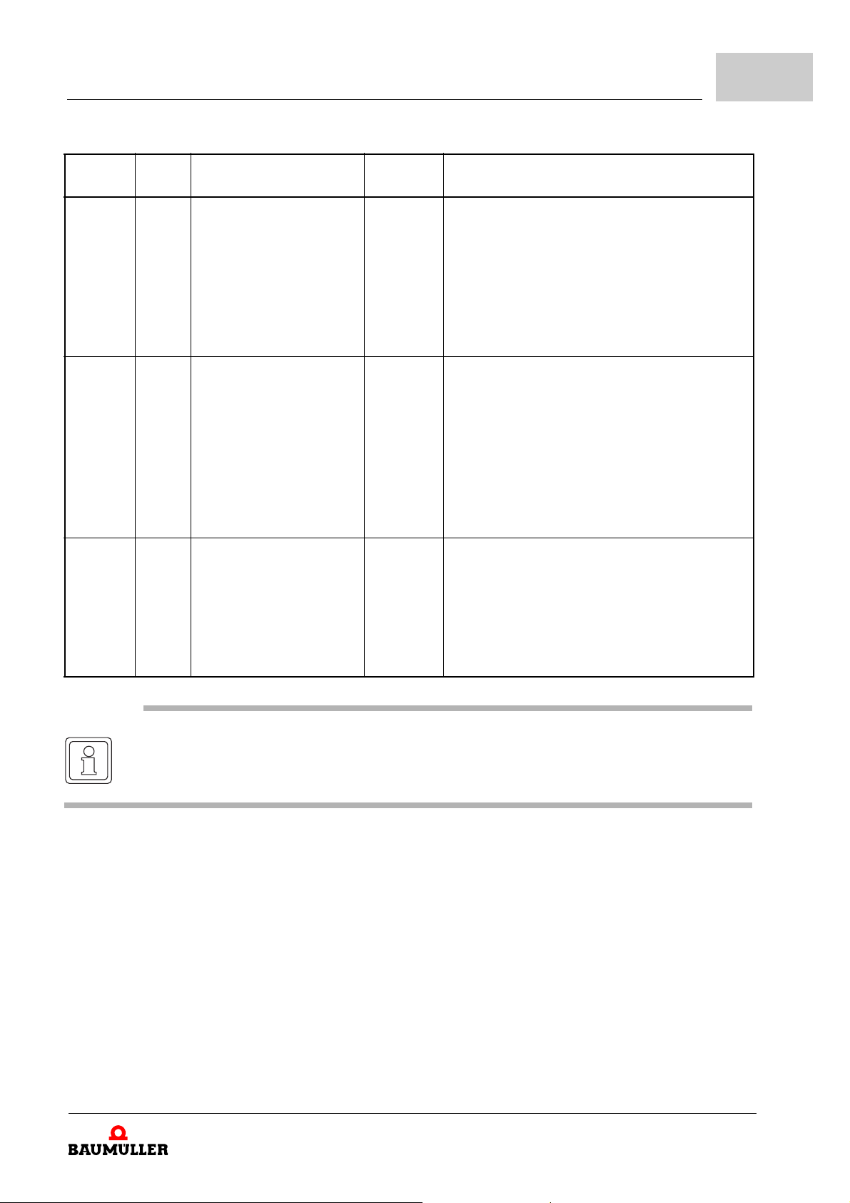
Error detection and troubleshooting
8
Fault
code
051A
051B
051C
hex
hex
hex
Fault
name
ocn Overcurrent during con-
oH2 Power board overheat PWM
EF External fault P0803
Fault description Error
stant speed operation
reaction
PWM
inhibit
inhibit
Corrective actions
m Short-circuit at motor output: Check for
possible poor insulation at the output line.
m Sudden increase in motor loading: Check
for possible motor stall.
m Device output power is too small: Re-
place the device with the next higher
power model.
m Ensure that the ambient temperature is
within the specified temperature range.
m Make sure that the ventilation holes are
not obstructed.
m Remove any foreign objects from the
heatsink and check for possible dirty heat
sink fins.
m Check the fan and clean it.
m When multi-function input terminals (MI3-
MI5 or MI7 to MI12) are set to external
fault, the device stops output U/T1, V/T2
and W/T3.
m Give RESET command after fault has
been cleared.
NOTE
CANopen error table see ZE.6.2 CANopen error display via digita l keypad– on page 155 and
error table in b maXX® 4400 parameter manual.
Manual b maXX® BM1000
Document No. 5.07003.06
of 172
85
Page 86

8.4
Warning code information
8.4 Warning code information
Warning code Warning name Warning descriptions Parameter
7 cE10 Warning: communication modbus P0862
8 oL2 Warning: motor load exceeded P1213
9 AUE Warning: auto tuning error 10 Uc Warning: under voltage 11 SE1 Warning: keypad copy parameter operation error 12 SE2 Warning: keypad copy parameter save error 13 PtC2 Warning: moto r PTC temperature exceeded P1012
14 PGEr Warning: PG (encoder) loss P1077
15 FbE Warning: PID feedback P1368
16 SAvE Warning: keypad copying 23 PE10 Warning: IO COM1 communication time out P0868
25 Lv Warning: DC BUS voltage has lower than standard
voltage
26 Aerr Warning: control board ACI (current) loss P0806
27 bb Warning: base block P1091 to P1100
33 CSdo Warning: CANopen SDO time out
34 CSfF Warning: CANopen buffer overflow
36 CbtU Warning: CANopen boot up error
50 cc01 Warning: At least one of the error counters of the
CANopen slave has reached the value 96
51 cc03 Warning : The SYNC-message is not received
within the configured time
52 UbCd Warning: communication error USB card P0868
53 cPt2 Warning: CAN error
P0297
86
of 172
Manual b maXX® BM1000
Document No. 5.07003.06 Baumüller Nürnberg GmbH
Page 87
8.5 Reset
Error detection and troubleshooting
There are three methods to reset the device aft er solvin g th e fau lt:
m Press key on keypad.
m Set external terminal to „RESET“ (set one of P1091 to P1094 to 05) and then set to be ON.
m Send „RESET“ command by communication.
NOTE
Make sure that RUN command or signal is OFF before executing RESET to prevent damage
or personal injury due to immediate operation.
8
Manual b maXX® BM1000
Document No. 5.07003.06
87
of 172
Page 88
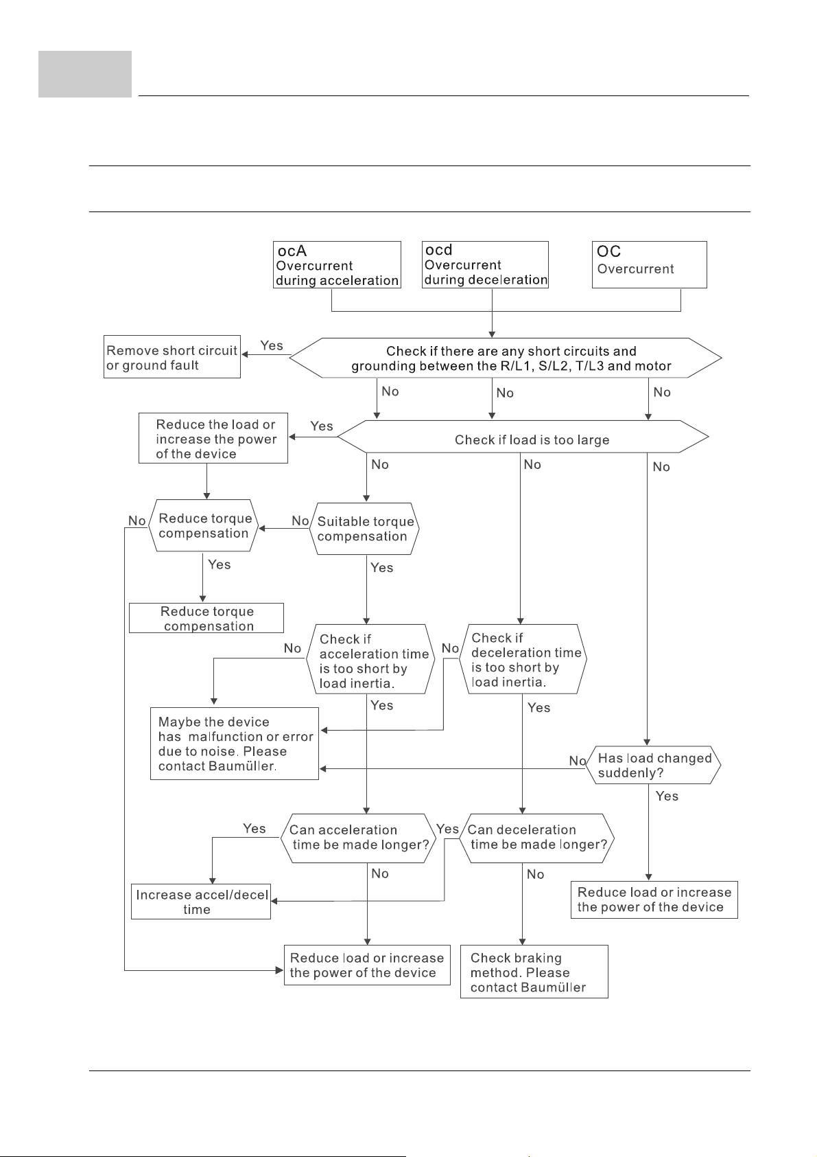
8.6
Troubleshooting
8.6 Troubleshooting
8.6.1 Overcurrent (OC)
88
of 172
Figure 47: Troubleshooting over current
Manual b maXX® BM1000
Document No. 5.07003.06 Baumüller Nürnberg GmbH
Page 89
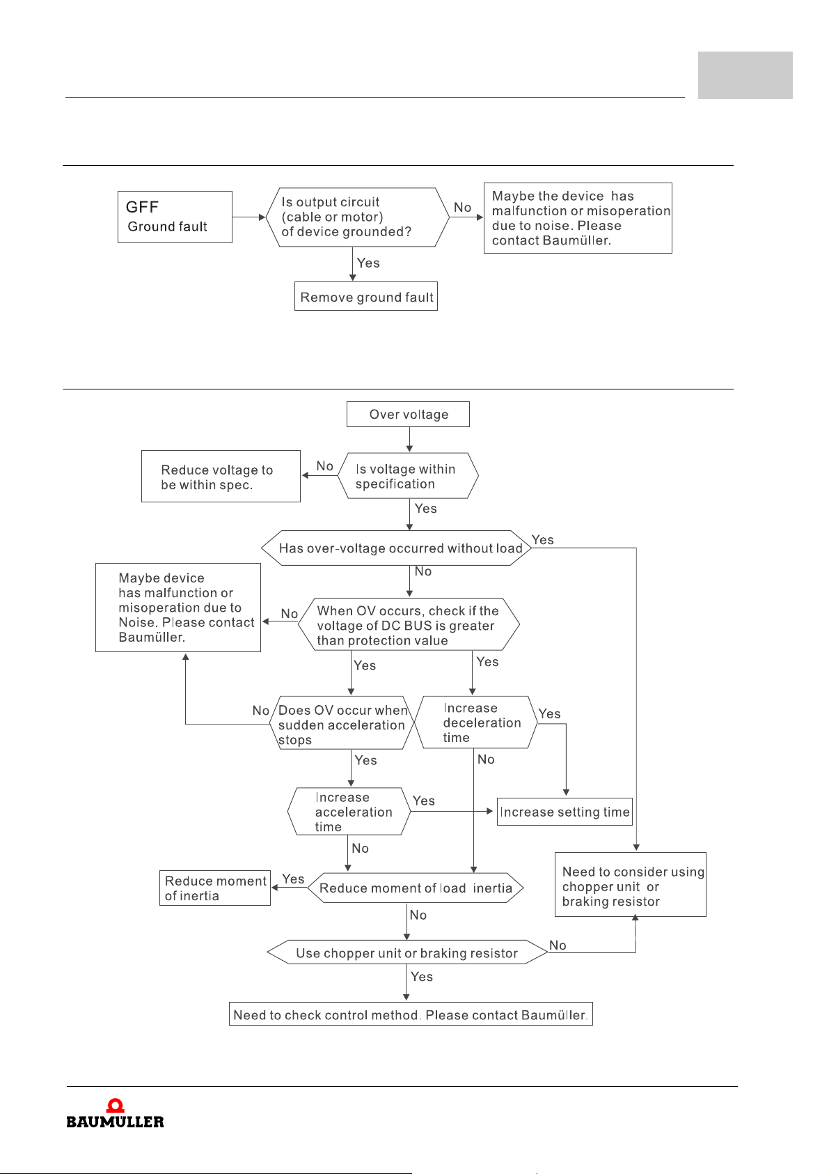
8.6.2 Ground fault
Figure 48: Troubleshooting ground fault
8.6.3 Overvoltage
Error detection and troubleshooting
8
Figure 49: Troubleshooting overvoltage
Manual b maXX® BM1000
Document No. 5.07003.06
89
of 172
Page 90
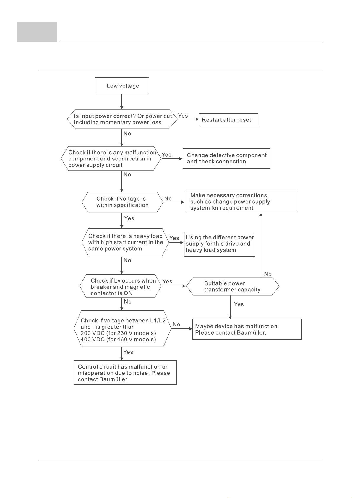
8.6
8.6.4 Low voltage (Lv)
Troubleshooting
90
of 172
Figure 50: Troubleshooting low voltage
Manual b maXX® BM1000
Document No. 5.07003.06 Baumüller Nürnberg GmbH
Page 91
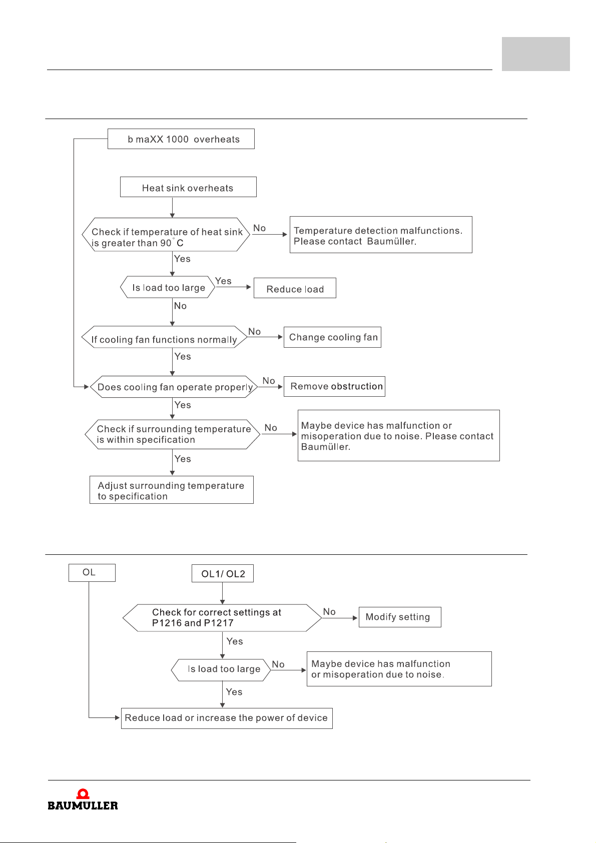
8.6.5 Overheat (OH)
Error detection and troubleshooting
8
Figure 51: Troubleshooting overheat
8.6.6 Overload OL
Figure 52: Troubleshooting overload
Manual b maXX® BM1000
Document No. 5.07003.06
91
of 172
Page 92
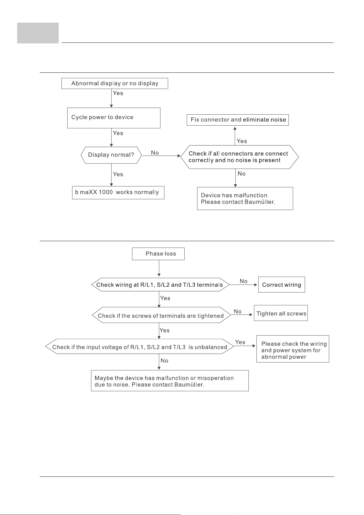
8.6
8.6.7 Keypad display is abnormal
Troubleshooting
Figure 53: Troubleshooting keypad display
8.6.8 Phase Loss (PHL)
92
of 172
Figure 54: Troubleshooting phase loss
Manual b maXX® BM1000
Document No. 5.07003.06 Baumüller Nürnberg GmbH
Page 93
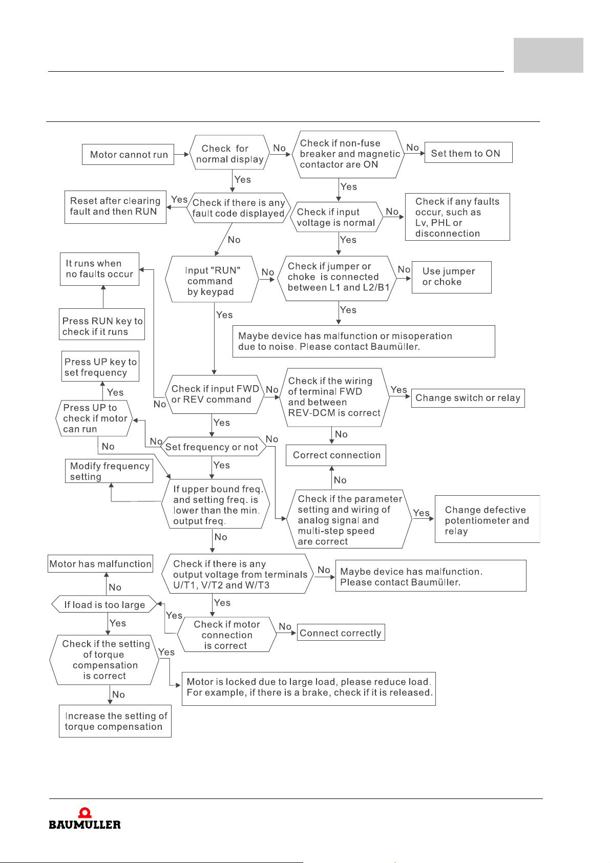
8.6.9 Motor doesn’t run
Error detection and troubleshooting
8
Figure 55: Troubleshooting motor doesn’t run
Manual b maXX® BM1000
Document No. 5.07003.06
93
of 172
Page 94
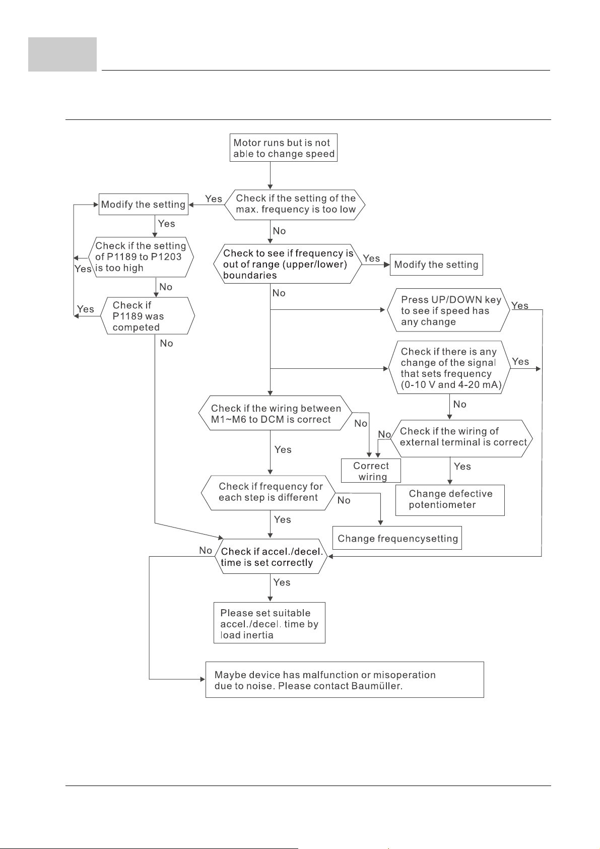
8.6
8.6.10 Motor speed cannot be changed
Troubleshooting
94
of 172
Figure 56: Troubleshooting motor speed cannot be changed
Manual b maXX® BM1000
Document No. 5.07003.06 Baumüller Nürnberg GmbH
Page 95
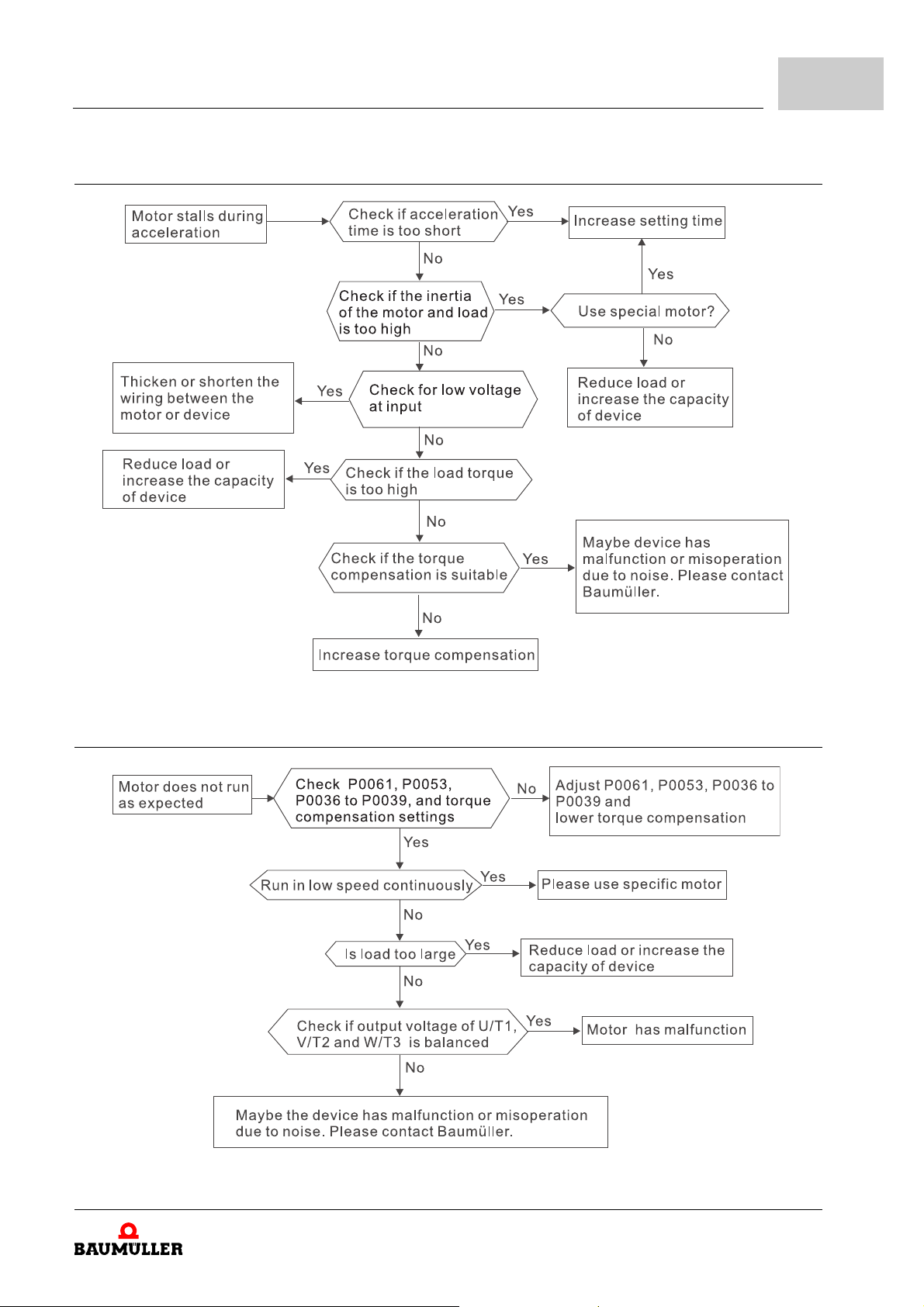
8.6.11 Motor stalls duri n g ac ce le rat io n
Error detection and troubleshooting
8
Figure 57: Troubleshooting motor stalls during acceleration
8.6.12 The motor does not run as expected
Figure 58: Troubleshooting motor does not run as expected
Manual b maXX® BM1000
Document No. 5.07003.06
95
of 172
Page 96

8.7
Electromagnetic/induction noise
8.7 Electromagnetic/induction noise
Many sources of noise surround the device and penetrate it by radiation or conduction. It may
cause malfunctioning of the control circuits and even damage the device. Of course, there are
solutions to increase the noise tolerance of the device. But this has its limits. Therefore it will be
the best to solve it from the outside as follows.
m Add surge suppressor on the relays and contacts to suppress switching surges.
m Shorten the wiring length of the control circuit or serial communication and keep them sepa-
rated from the power circuit wiring.
m Comply with the wiring regulations by using shielded wires and isolation amplifiers for long
length.
m The grounding terminal should comply with the local regulations an d be grounded indep en-
dently, i.e. not to have common ground with electric welding machines and other power
equipment.
m Connect a noise filter at the mains input terminal of the device to filter noise from the power
circuit. b
In short, solutions for electromagnetic noise exist of „no product“ (disconnect disturbing equipment), „no spread“ (limit emission for disturbing equipment) an d „no receive“ (enhan ce immuni ty).
maXX® 1000 can have a built-in filter as option.
8.8 Environmental condition
Since the b maXX® 1000 is an electronic device, you should comply with the environmental conditions as stated in ZD.1 Required environmental conditions– from page 140. Here are some
remedial measures if necessary.
m To prevent vibration, the use of anti-vibration dampers is the last choice. Vibrations must be
within the specification. Vibration causes mechanical stress and it should not occur frequent
ly, continuously or repeatedly to prevent damage to the device.
m Store the device in a clean and dry location, free from corrosive fumes/du st to pr event corro -
sion and poor contacts. Poor insulation in a humid location can cause sho rt-circuits. If necessary, install the device in a dust-proof and painted enclosu re an d in pa rticular situation s, use
a completely sealed enclosure.
m The ambient temperature should be within the spe cification. Too high or too lo w temperature
will affect the lifetime and reliability. For semiconductor components, damage will occur once
any specification is out of range. Therefore, it is necessary to periodically check air quality
and the cooling fan and provide extra cooling of necessary. In addition, the microcomputer
may not work in extremely low temperatures, making cabinet heating necessary.
m Store within a relative humidity range of 0 % to 90 % and non-condensing environment. Use
an air conditioner and/or exsiccator.
-
96
of 172
Manual b maXX® BM1000
Document No. 5.07003.06 Baumüller Nürnberg GmbH
Page 97
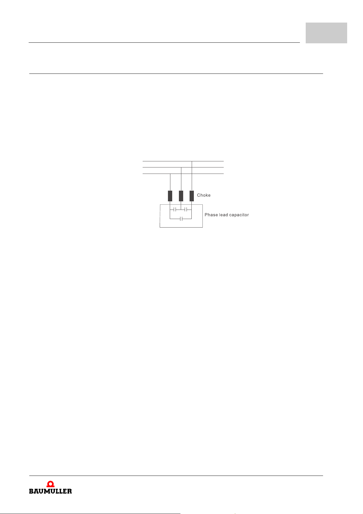
8.9 Affecting other machines
A b maXX® 1000 may affect the operation of other machines due to many reasons. Some solutions are:
High harmonics at power side
n High harmonics at power side during running can be improved by
m Separate the power system: Use a transformer for the device.
m Use a choke or rectifier at the power input terminal of the de vice or decrease high har-
monic by multiple circuit.
m If phase lead capacitors are used (never on the device output), use chokes to prevent
damage to the capacitors from high harmoni cs.
Error detection and troubleshooting
8
Figure 59: Phase lead capacitors
Motor temperature rises
n When the motor is a standard motor with fan, the cooling will be bad at low speeds, causing
the motor to overheat. Besides, high harmonics at the output increases copper and core
losses. The following measures should be used depending on load and operation range.
m Use a motor with independent ventilation (forced external coolin g) or increase the mo-
tor rated power.
m Use a special inverter-duty motor.
m Do NOT run at low speeds for long time.
Manual b maXX® BM1000
Document No. 5.07003.06
97
of 172
Page 98

8.9
Affecting other machines
98
of 172
Manual b maXX® BM1000
Document No. 5.07003.06 Baumüller Nürnberg GmbH
Page 99
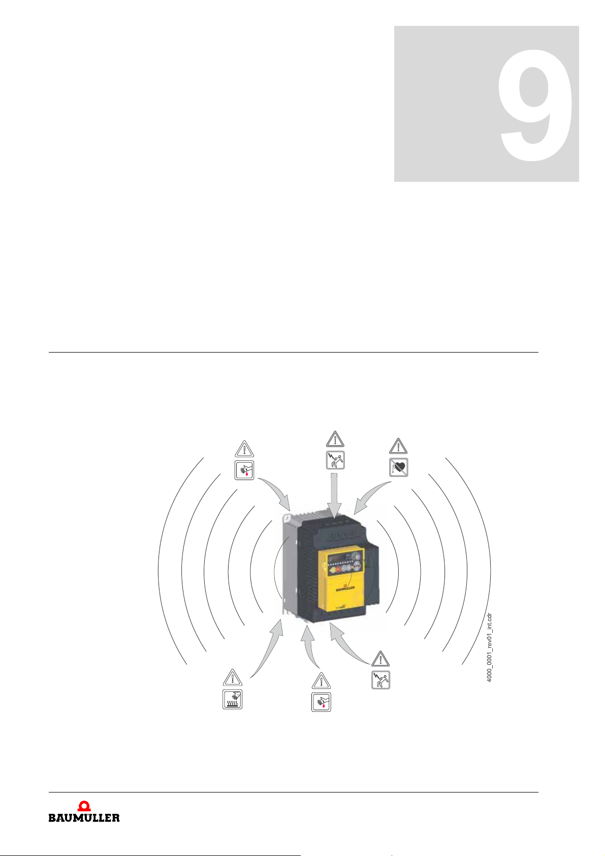
In this chapter we describe, how you can safely maintain your device.
9.1 Safety instructions
h Refer to ZFundamental safety instructions– from page 9.
h Refer to the dange r ar ea s of the de vice s.
9MAINTENANCE
Figure 60: Danger areas b maXX® BM1000
Manual b maXX® BM1000
Document No. 5.07003.06
99
of 172
Page 100
9.2
Environmental conditions
9.2 Environmental conditions
If the prescribed environmental conditions are complied with, the device is ma intenancefree. The prescribed environmental conditions are to be found in chapter
Technical data– from page 139. The most important prescribed environmental conditions
are:
m Dustless ambient air
m Temperature: min. -10 °C to max. +50 °C (14 - 122 °F)
min. -10 °C to max +40 °C (14 - 104 °F)
for side-by-side mounting
m Relative air humidity: 0 to 90 %, no condensation allowed
m (Operational-) height: Altitude up to 1000 m
m Atmosphere pressure: 86 - 106 kPa
m Vibration: <20 Hz: 9.80 m/s² (1 G) max.
20 - 50 Hz: 5.88 m/s² (0.6 G)
9.3 Inspection intervals - maintenance notes
ZAppendix D -
b maXX® 1000 drives are based on solid-state electronics technology. Preventive maintenance is required to keep the device in its optimal condition, and to ensure a long life.
It is recommended to have a qualified technician perform a check-up of the device regu
larly.
Daily inspection: Basic check-up items to detect if there were any abnormalities during operation are:
m Whether the motors are operating as expected.
m Whether the installation environment is abnormal.
m Whether the cooling system is operating as expected.
m Whether any irregular vibration or sound occurred during operation.
m Whether the motors are overheating during operation.
m Always check the input voltage of the device with a voltmeter.
Periodic inspection:
Before the check-up, always turn off the input power and remove the cover. Wait at least
10 minutes after all display lamps have gone out, and then confirm that the capacitors
have fully discharged by measuring the voltage between
than 25 VDC.
DANGER
The following will occur, if you do not observe this danger information:
m serious personal injury m death
and . It should be less
-
100
of 172
The hazard is: electricity.
m Disconnect power before processing!
m Only qualified personnel shall install, wire and maintain the devices. Please take off any
metal objects, such as watches and rings, before operation. And only insulated tools are
allowed.
m Never reassemble internal components or wiring.
m Prevent electric shocks.
Manual b maXX® BM1000
Document No. 5.07003.06 Baumüller Nürnberg GmbH
 Loading...