

Page 1
Single Power Unit
BUM64S/A/F
Manual
E
5.01056.03
Page 2

Title Manual
Product Single Power Unit, BUM64S/A/F
Version 5.01056.03
Status 2003-12-17
Copyright These operating instructions may be copied by the owner in
any quantity but only for internal use. For other purposes
these operating instructions and extracts thereof must not
be copied or reproduced.
Use and disclosure of information contained in these operating instructions are not permitted.
Designations and company marks contained in these operating instructions may be brand names, the use of which by
third parties for their own purposes may violate the rights of
the holders.
Obligatory These operating instructions are part of the equipment/ma-
chine. These operating instructions must be available to the
operator at all times and must be in a legible condition. If the
equipment/machine is sold or moved to a different location
these operating instructions must be passed on by the own
er together with the equipment/machine.
After any sale of the equipment/machine this original and all
copies must be handed over to the buyer. After disposal or
any other end of use this original and all copies must be de
stroyed.
-
-
When the present operating instructions are handed over,
corresponding sets of operating instructions of a previous
version are automatically invalidated. Please notice that
specifications/data/information are
.
ing to the printing date
binding
calculations.
Baumüller Nürnberg Electronic GmbH & Co. KG reserves
the right, in developing its products further, to change the
technical specifications and the handling of the products
concerned without prior notice.
No liability can be accepted concerning the correctness of
the operating instructions unless otherwise specified in the
General Conditions of Sale and Delivery.
Manufacturer Baumüller Nürnberg Electronic GmbH & Co. KG
Ostendstr. 80 - 90
D-90482 Nürnberg
Germany
Tel. +49 9 11 54 32 - 0 Fax: +49 9 11 54 32 - 1 30
www.baumueller.de
according to the measurement, computation and
These statements are
current values accord
-
not legally
Page 3

Table of contents
1 Introduction . . . . . . . . . . . . . . . . . . . . . . . . . . . . . . . . . . . . . . . . . . . . . . . . . . . . . . . . . . . . . . 7
1.1 First steps . . . . . . . . . . . . . . . . . . . . . . . . . . . . . . . . . . . . . . . . . . . . . . . . . . . . . . . . . . . 7
1.2 Terms used . . . . . . . . . . . . . . . . . . . . . . . . . . . . . . . . . . . . . . . . . . . . . . . . . . . . . . . . . . 7
1.3 Obligation and liability . . . . . . . . . . . . . . . . . . . . . . . . . . . . . . . . . . . . . . . . . . . . . . . . . . 7
1.3.1 Observing danger- and safety information . . . . . . . . . . . . . . . . . . . . . . . . . . . . . . . . . 7
1.3.2 Dangers when handling this appliance . . . . . . . . . . . . . . . . . . . . . . . . . . . . . . . . . . . . 8
1.3.3 Guarantee and liability. . . . . . . . . . . . . . . . . . . . . . . . . . . . . . . . . . . . . . . . . . . . . . . . . 8
2 Fundamental security information . . . . . . . . . . . . . . . . . . . . . . . . . . . . . . . . . . . . . . . . . . . 11
2.1 Hazard information and commands. . . . . . . . . . . . . . . . . . . . . . . . . . . . . . . . . . . . . . . 11
2.1.1 Hazard information structure. . . . . . . . . . . . . . . . . . . . . . . . . . . . . . . . . . . . . . . . . . . 12
2.1.2 Form of the hazard sign (triangular or round) . . . . . . . . . . . . . . . . . . . . . . . . . . . . . . 13
2.1.2.1 Hazard information on personal injury . . . . . . . . . . . . . . . . . . . . . . . . . . . . . . . . . . . 13
2.1.2.2 Hazard information on property damage. . . . . . . . . . . . . . . . . . . . . . . . . . . . . . . . . 18
2.1.2.3 Command signs used . . . . . . . . . . . . . . . . . . . . . . . . . . . . . . . . . . . . . . . . . . . . . . . 18
2.2 Information sign . . . . . . . . . . . . . . . . . . . . . . . . . . . . . . . . . . . . . . . . . . . . . . . . . . . . . . 19
2.3 Application according to the terms. . . . . . . . . . . . . . . . . . . . . . . . . . . . . . . . . . . . . . . . 19
2.4 Non-appropriate application. . . . . . . . . . . . . . . . . . . . . . . . . . . . . . . . . . . . . . . . . . . . . 19
2.5 Education of the personnel . . . . . . . . . . . . . . . . . . . . . . . . . . . . . . . . . . . . . . . . . . . . . 20
2.6 Reconstructing the appliance . . . . . . . . . . . . . . . . . . . . . . . . . . . . . . . . . . . . . . . . . . . 20
2.7 Disposal of the appliance. . . . . . . . . . . . . . . . . . . . . . . . . . . . . . . . . . . . . . . . . . . . . . . 20
2.8 Fire fighting . . . . . . . . . . . . . . . . . . . . . . . . . . . . . . . . . . . . . . . . . . . . . . . . . . . . . . . . . 21
3 Packing and Transport . . . . . . . . . . . . . . . . . . . . . . . . . . . . . . . . . . . . . . . . . . . . . . . . . . . . 23
3.1 Transport . . . . . . . . . . . . . . . . . . . . . . . . . . . . . . . . . . . . . . . . . . . . . . . . . . . . . . . . . . . 23
3.2 Unpacking . . . . . . . . . . . . . . . . . . . . . . . . . . . . . . . . . . . . . . . . . . . . . . . . . . . . . . . . . . 23
3.3 Disposal of the packaging . . . . . . . . . . . . . . . . . . . . . . . . . . . . . . . . . . . . . . . . . . . . . . 24
3.4 Transportation precautions . . . . . . . . . . . . . . . . . . . . . . . . . . . . . . . . . . . . . . . . . . . . . 24
4 Description of the unit. . . . . . . . . . . . . . . . . . . . . . . . . . . . . . . . . . . . . . . . . . . . . . . . . . . . . 25
4.1 Variants . . . . . . . . . . . . . . . . . . . . . . . . . . . . . . . . . . . . . . . . . . . . . . . . . . . . . . . . . . . . 26
4.2 Overview of hazardous areas . . . . . . . . . . . . . . . . . . . . . . . . . . . . . . . . . . . . . . . . . . . 27
4.3 Characteristics of the unit - type key . . . . . . . . . . . . . . . . . . . . . . . . . . . . . . . . . . . . . . 28
4.4 Block switching diagram . . . . . . . . . . . . . . . . . . . . . . . . . . . . . . . . . . . . . . . . . . . . . . . 29
5 Mounting. . . . . . . . . . . . . . . . . . . . . . . . . . . . . . . . . . . . . . . . . . . . . . . . . . . . . . . . . . . . . . . . 31
5.1 Hazardous areas during mounting. . . . . . . . . . . . . . . . . . . . . . . . . . . . . . . . . . . . . . . . 31
5.2 Mounting steps . . . . . . . . . . . . . . . . . . . . . . . . . . . . . . . . . . . . . . . . . . . . . . . . . . . . . . 32
5.2.1 Select a switching cabinet. . . . . . . . . . . . . . . . . . . . . . . . . . . . . . . . . . . . . . . . . . . . . 32
5.2.1.1 Space requirements - dimensional drawings. . . . . . . . . . . . . . . . . . . . . . . . . . . . . . 33
5.3 Producing the drill holes/threaded holes and the cut-out. . . . . . . . . . . . . . . . . . . . . . . 34
5.4 Mounting the unit . . . . . . . . . . . . . . . . . . . . . . . . . . . . . . . . . . . . . . . . . . . . . . . . . . . . . 35
5.4.1 BUM64S mounting . . . . . . . . . . . . . . . . . . . . . . . . . . . . . . . . . . . . . . . . . . . . . . . . . . 35
5.4.2 Mounting BUM64 window variant A/F . . . . . . . . . . . . . . . . . . . . . . . . . . . . . . . . . . . . 37
5.4.2.1 Coolant . . . . . . . . . . . . . . . . . . . . . . . . . . . . . . . . . . . . . . . . . . . . . . . . . . . . . . . . . . 38
5.4.2.2 Connecting BUM64F to coolant circulation . . . . . . . . . . . . . . . . . . . . . . . . . . . . . . . 40
6 Installation . . . . . . . . . . . . . . . . . . . . . . . . . . . . . . . . . . . . . . . . . . . . . . . . . . . . . . . . . . . . . . 41
6.1 General hazard information . . . . . . . . . . . . . . . . . . . . . . . . . . . . . . . . . . . . . . . . . . . . . 41
6.1.1 Voltage test . . . . . . . . . . . . . . . . . . . . . . . . . . . . . . . . . . . . . . . . . . . . . . . . . . . . . . . . 43
Manual Single Power Unit BUM64S/A/F
Document no.: 5.01056.03
3
of 118
Page 4

Table of contents
6.2 Hazardous areas at installation . . . . . . . . . . . . . . . . . . . . . . . . . . . . . . . . . . . . . . . . . . 43
6.3 Requirements on the electrical power network . . . . . . . . . . . . . . . . . . . . . . . . . . . . . . 43
6.4 Cable requirements . . . . . . . . . . . . . . . . . . . . . . . . . . . . . . . . . . . . . . . . . . . . . . . . . . . 44
6.5 Connections . . . . . . . . . . . . . . . . . . . . . . . . . . . . . . . . . . . . . . . . . . . . . . . . . . . . . . . . . 44
6.5.1 Power terminals . . . . . . . . . . . . . . . . . . . . . . . . . . . . . . . . . . . . . . . . . . . . . . . . . . . . . 45
6.5.2 Control connections . . . . . . . . . . . . . . . . . . . . . . . . . . . . . . . . . . . . . . . . . . . . . . . . . . 46
6.5.2.1 Control terminal X99A . . . . . . . . . . . . . . . . . . . . . . . . . . . . . . . . . . . . . . . . . . . . . . . 47
6.5.2.2 Control terminal X99AB . . . . . . . . . . . . . . . . . . . . . . . . . . . . . . . . . . . . . . . . . . . . . . 48
6.5.2.3 Safety relay X68. . . . . . . . . . . . . . . . . . . . . . . . . . . . . . . . . . . . . . . . . . . . . . . . . . . . 50
6.6 Fuses of the appliance . . . . . . . . . . . . . . . . . . . . . . . . . . . . . . . . . . . . . . . . . . . . . . . . . 52
6.7 EMC requirements on cable routing (EMC information). . . . . . . . . . . . . . . . . . . . . . . . 52
6.7.1 German EMC law (EMVG). . . . . . . . . . . . . . . . . . . . . . . . . . . . . . . . . . . . . . . . . . . . . 52
6.7.2 Measures to ensure EMC . . . . . . . . . . . . . . . . . . . . . . . . . . . . . . . . . . . . . . . . . . . . . 52
6.7.2.1 Cabling . . . . . . . . . . . . . . . . . . . . . . . . . . . . . . . . . . . . . . . . . . . . . . . . . . . . . . . . . . . 53
6.7.2.2 Grounding. . . . . . . . . . . . . . . . . . . . . . . . . . . . . . . . . . . . . . . . . . . . . . . . . . . . . . . . . 55
6.7.2.3 Screening . . . . . . . . . . . . . . . . . . . . . . . . . . . . . . . . . . . . . . . . . . . . . . . . . . . . . . . . . 56
6.7.2.4 Filtering. . . . . . . . . . . . . . . . . . . . . . . . . . . . . . . . . . . . . . . . . . . . . . . . . . . . . . . . . . . 57
6.7.2.5 Filter mounting . . . . . . . . . . . . . . . . . . . . . . . . . . . . . . . . . . . . . . . . . . . . . . . . . . . . . 57
6.7.2.6 Discharge currents . . . . . . . . . . . . . . . . . . . . . . . . . . . . . . . . . . . . . . . . . . . . . . . . . . 57
6.8 Connection diagram . . . . . . . . . . . . . . . . . . . . . . . . . . . . . . . . . . . . . . . . . . . . . . . . . . . 58
6.9 Fastening according to UL . . . . . . . . . . . . . . . . . . . . . . . . . . . . . . . . . . . . . . . . . . . . . . 60
7 Commissioning. . . . . . . . . . . . . . . . . . . . . . . . . . . . . . . . . . . . . . . . . . . . . . . . . . . . . . . . . . . 61
7.1 Requirements the executing personnel must meet . . . . . . . . . . . . . . . . . . . . . . . . . . . 61
7.2 Checking the mounting. . . . . . . . . . . . . . . . . . . . . . . . . . . . . . . . . . . . . . . . . . . . . . . . . 62
7.3 Checking the installation . . . . . . . . . . . . . . . . . . . . . . . . . . . . . . . . . . . . . . . . . . . . . . . 62
7.4 Checking the safety devices. . . . . . . . . . . . . . . . . . . . . . . . . . . . . . . . . . . . . . . . . . . . . 63
7.5 Commissioning sequence . . . . . . . . . . . . . . . . . . . . . . . . . . . . . . . . . . . . . . . . . . . . . . 63
8 Operation. . . . . . . . . . . . . . . . . . . . . . . . . . . . . . . . . . . . . . . . . . . . . . . . . . . . . . . . . . . . . . . . 65
8.1 Safety regulations. . . . . . . . . . . . . . . . . . . . . . . . . . . . . . . . . . . . . . . . . . . . . . . . . . . . . 65
8.2 Monitoring functions and their messages. . . . . . . . . . . . . . . . . . . . . . . . . . . . . . . . . . . 65
8.2.1 Monitoring functions of feed module . . . . . . . . . . . . . . . . . . . . . . . . . . . . . . . . . . . . . 66
8.2.2 Monitoring functions of motor-side power module. . . . . . . . . . . . . . . . . . . . . . . . . . . 66
8.3 Ready-for-use (= BB) . . . . . . . . . . . . . . . . . . . . . . . . . . . . . . . . . . . . . . . . . . . . . . . . . . 66
8.4 Monitoring functions . . . . . . . . . . . . . . . . . . . . . . . . . . . . . . . . . . . . . . . . . . . . . . . . . . . 69
8.4.1 Monitoring functions of feed module . . . . . . . . . . . . . . . . . . . . . . . . . . . . . . . . . . . . . 70
8.4.2 Monitoring functions of motor-side power module. . . . . . . . . . . . . . . . . . . . . . . . . . . 71
8.4.3 Messages over relay contacts . . . . . . . . . . . . . . . . . . . . . . . . . . . . . . . . . . . . . . . . . . 72
9 Maintenance . . . . . . . . . . . . . . . . . . . . . . . . . . . . . . . . . . . . . . . . . . . . . . . . . . . . . . . . . . . . . 73
9.1 Inspection interval . . . . . . . . . . . . . . . . . . . . . . . . . . . . . . . . . . . . . . . . . . . . . . . . . . . . 73
10 Repair . . . . . . . . . . . . . . . . . . . . . . . . . . . . . . . . . . . . . . . . . . . . . . . . . . . . . . . . . . . . . . . . . . 75
11 Setting out of operation, storage . . . . . . . . . . . . . . . . . . . . . . . . . . . . . . . . . . . . . . . . . . . . 77
11.1 Demands on the personnel . . . . . . . . . . . . . . . . . . . . . . . . . . . . . . . . . . . . . . . . . . . . . 77
11.2 Safety regulations. . . . . . . . . . . . . . . . . . . . . . . . . . . . . . . . . . . . . . . . . . . . . . . . . . . . . 77
11.3 Setting out of operation . . . . . . . . . . . . . . . . . . . . . . . . . . . . . . . . . . . . . . . . . . . . . . . . 78
11.4 Demounting . . . . . . . . . . . . . . . . . . . . . . . . . . . . . . . . . . . . . . . . . . . . . . . . . . . . . . . . . 78
11.5 Storage conditions . . . . . . . . . . . . . . . . . . . . . . . . . . . . . . . . . . . . . . . . . . . . . . . . . . . . 78
11.6 Maintenance during the storage. . . . . . . . . . . . . . . . . . . . . . . . . . . . . . . . . . . . . . . . . . 78
11.7 Re-commissioning . . . . . . . . . . . . . . . . . . . . . . . . . . . . . . . . . . . . . . . . . . . . . . . . . . . . 78
4
of 118
12 Disposal. . . . . . . . . . . . . . . . . . . . . . . . . . . . . . . . . . . . . . . . . . . . . . . . . . . . . . . . . . . . . . . . . 79
12.1 Safety regulations. . . . . . . . . . . . . . . . . . . . . . . . . . . . . . . . . . . . . . . . . . . . . . . . . . . . . 79
Manual Single Power Unit BUM64S/A/F
Document no.: 5.01056.03 Baumüller Nürnberg Electronic GmbH & Co. KG
Page 5

Table of contents
12.2 Demands on the personnel . . . . . . . . . . . . . . . . . . . . . . . . . . . . . . . . . . . . . . . . . . . . . 79
12.3 Disposal instructions . . . . . . . . . . . . . . . . . . . . . . . . . . . . . . . . . . . . . . . . . . . . . . . . . . 80
12.3.1 Modules. . . . . . . . . . . . . . . . . . . . . . . . . . . . . . . . . . . . . . . . . . . . . . . . . . . . . . . . . . . 80
12.4 Recycling plants / offices . . . . . . . . . . . . . . . . . . . . . . . . . . . . . . . . . . . . . . . . . . . . . . . 81
Appendix A - Abbreviations . . . . . . . . . . . . . . . . . . . . . . . . . . . . . . . . . . . . . . . . . . . . . . . . . . . 83
Appendix B - Accessories . . . . . . . . . . . . . . . . . . . . . . . . . . . . . . . . . . . . . . . . . . . . . . . . . . . . 87
B.1 Connectors . . . . . . . . . . . . . . . . . . . . . . . . . . . . . . . . . . . . . . . . . . . . . . . . . . . . . . . . . . 87
B.2 Water cooling . . . . . . . . . . . . . . . . . . . . . . . . . . . . . . . . . . . . . . . . . . . . . . . . . . . . . . . . 87
B.3 Fuses . . . . . . . . . . . . . . . . . . . . . . . . . . . . . . . . . . . . . . . . . . . . . . . . . . . . . . . . . . . . . . 88
B.3.1 Extreme range fuse gR (appliance and cable) . . . . . . . . . . . . . . . . . . . . . . . . . . . . . . 88
B.3.2 Semiconductor fuse aR (appliance) . . . . . . . . . . . . . . . . . . . . . . . . . . . . . . . . . . . . . . 88
B.4 Line reactors . . . . . . . . . . . . . . . . . . . . . . . . . . . . . . . . . . . . . . . . . . . . . . . . . . . . . . . . . 89
B.5 EMC accessories . . . . . . . . . . . . . . . . . . . . . . . . . . . . . . . . . . . . . . . . . . . . . . . . . . . . . 90
Appendix C Declaration of Conformity /
Decl. by Manufacturer /
UL-cert. . . . . . . . . . . . . . . . . . . . . . . . . . . . . . . . . . . . . . . . . . . . . . . . . . . . . . . . . . . . . . . . . . . . . 91
C.1 What is an EC directive? . . . . . . . . . . . . . . . . . . . . . . . . . . . . . . . . . . . . . . . . . . . . . . . 91
C.2 What the CE symbol indicates . . . . . . . . . . . . . . . . . . . . . . . . . . . . . . . . . . . . . . . . . . . 91
C.3 Definition of the term Declaration of Conformity . . . . . . . . . . . . . . . . . . . . . . . . . . . . . . 92
C.4 Definition of the term Declaration by Manufacturer . . . . . . . . . . . . . . . . . . . . . . . . . . . 92
C.5 Declaration of Conformity . . . . . . . . . . . . . . . . . . . . . . . . . . . . . . . . . . . . . . . . . . . . . . . 93
C.6 Declaration by Manufacturer. . . . . . . . . . . . . . . . . . . . . . . . . . . . . . . . . . . . . . . . . . . . . 94
C.7 UL-certification . . . . . . . . . . . . . . . . . . . . . . . . . . . . . . . . . . . . . . . . . . . . . . . . . . . . . . . 95
Appendix D - Technical specifications . . . . . . . . . . . . . . . . . . . . . . . . . . . . . . . . . . . . . . . . . 97
D.1 Requirements on the power supply . . . . . . . . . . . . . . . . . . . . . . . . . . . . . . . . . . . . . . . 98
D.2 Required environmental conditions . . . . . . . . . . . . . . . . . . . . . . . . . . . . . . . . . . . . . . . 99
D.3 Electrical specifications. . . . . . . . . . . . . . . . . . . . . . . . . . . . . . . . . . . . . . . . . . . . . . . . 101
D.4 Fuses . . . . . . . . . . . . . . . . . . . . . . . . . . . . . . . . . . . . . . . . . . . . . . . . . . . . . . . . . . . . . 103
D.5 BUM64S - non-electrical data. . . . . . . . . . . . . . . . . . . . . . . . . . . . . . . . . . . . . . . . . . . 103
D.6 BUM64A - non-electrical data. . . . . . . . . . . . . . . . . . . . . . . . . . . . . . . . . . . . . . . . . . . 103
D.7 BUM64F - non-electrical data . . . . . . . . . . . . . . . . . . . . . . . . . . . . . . . . . . . . . . . . . . . 103
D.8 Cable from mains supply to appliance . . . . . . . . . . . . . . . . . . . . . . . . . . . . . . . . . . . . 104
D.9 Cable for control voltage supply / signals . . . . . . . . . . . . . . . . . . . . . . . . . . . . . . . . . . 104
D.10 Cable from appliance to motor . . . . . . . . . . . . . . . . . . . . . . . . . . . . . . . . . . . . . . . . . . 105
D.11 Electrical motor to be connected . . . . . . . . . . . . . . . . . . . . . . . . . . . . . . . . . . . . . . . . 105
Appendix E - Safety relay . . . . . . . . . . . . . . . . . . . . . . . . . . . . . . . . . . . . . . . . . . . . . . . . . . . . 107
E.1 Methods to avoid an unexpected starting . . . . . . . . . . . . . . . . . . . . . . . . . . . . . . . . . . 107
E.2 Safety categories . . . . . . . . . . . . . . . . . . . . . . . . . . . . . . . . . . . . . . . . . . . . . . . . . . . . 108
E.3 The safety relay . . . . . . . . . . . . . . . . . . . . . . . . . . . . . . . . . . . . . . . . . . . . . . . . . . . . . 109
E.4 Application example for machine of category 3 . . . . . . . . . . . . . . . . . . . . . . . . . . . . . 111
E.5 Application example for machine of category 4 . . . . . . . . . . . . . . . . . . . . . . . . . . . . . 112
E.6 Service time . . . . . . . . . . . . . . . . . . . . . . . . . . . . . . . . . . . . . . . . . . . . . . . . . . . . . . . . 114
Table of figures . . . . . . . . . . . . . . . . . . . . . . . . . . . . . . . . . . . . . . . . . . . . . . . . . . . . . . . . . . . . 115
Index . . . . . . . . . . . . . . . . . . . . . . . . . . . . . . . . . . . . . . . . . . . . . . . . . . . . . . . . . . . . . . . . . . . . . 117
Manual Single Power Unit BUM64S/A/F
Document no.: 5.01056.03
5
of 118
Page 6

Table of contents
6
of 118
Manual Single Power Unit BUM64S/A/F
Document no.: 5.01056.03 Baumüller Nürnberg Electronic GmbH & Co. KG
Page 7

1.1 First steps
1
1I
NTRODUCTION
In this chapter we describe the first steps you should carry out after you have received
your appliance. We will give you a definition of terms used throughout this documentation
and we will give you information about what must be observed when using this appliance.
check the scope of delivery,
1
pass on the supplied documentation to the respective departments.
2
take care of suitable personnel for mounting, installation and commissioning.
3
hand over this manual to the personnel for mounting, installation and commissioning.
4
Make sure, that particularly the safety information is understood and will be observed.
1.2 Terms used
In this documentation for the Baumüller product “Single Power Unit“ we will also use the
term "appliance". In the appendix you will find a list of all terms used, see ZAppendix A -
Abbreviations– from page 83.
1.3 Obligation and liability
In order to enable you to run this appliance with maximum safety it is essential that you
know and obey the danger- and safety information given in this documentation.
1.3.1 Observing danger- and safety information
To keep you from damage of personnel and property we will use unified danger information signs in this documentation.
ZPacking and Transport– from page 23
see
.
Manual Single Power Unit BUM64S/A/F
Document no.: 5.01056.03
7
of 118
Page 8

1.3
Obligation and liability
WARNING
The following
m
serious personal injury m death
All persons, who work at or with this appliance, must have knowledge of and observe all hazard and security information given in this manual.
Furthermore all persons who work with this appliance must in addition know and observe all
local instructions and regulations.
1.3.2 Dangers when handling this appliance
This “Single Power Unit“ appliance has been developed and produced according to the
state-of-the-art technics also keeping the respective guidelines and standards. Still the
handling of the appliance can hold dangers. An overview of possible dangers you will find
in chapter
When there is a hazard you will always find a detailed security information at the respective location.
1.3.3 Guarantee and liability
The “Terms of sale and delivery“ of Baumüller Nürnberg Electronic GmbH & Co. are applied generally. These are available to you at the latest since the contract was assured.
Claims of guarantee or liability towards Baumüller Nürnberg Electronic GmbH
rejected if one or more of the reasons listed below has/have been the cause of the dam
age/s:
m
m
n
m
m
m
may occur,
ZFundamental security information– from page 11
you have disregarded the information given in this manual
you have used this appliance within a non-appropriate application
this appliance you have
m
unskillfully mounted
m
unskillfully connected
m
unskillfully commissioned
m
unskillfully operated
m
unskillfully or not maintained
m
let be mounted, connected, commissioned, operated and/or maintained by not or
not adequate qualified personnel
m
overloaded
n
operated it with
m
defective security devices
m
not properly mounted or without security devices
m
not efficient safety- and protection devices
m
environmental conditions being not within the specified values
you have reconstructed this appliance without written permission of Baumüller Nürnberg Electronic GmbH & Co. KG.
you have disregarded instructions concerning maintenance in the component manuals
you have failed to monitor parts of wear and tear properly
if you do not observe this warning information:
.
& Co. are
-
8
of 118
Manual Single Power Unit BUM64S/A/F
Document no.: 5.01056.03 Baumüller Nürnberg Electronic GmbH & Co. KG
Page 9

Introduction
m
you have carried out a repair job unskillfully
m
you have unskillfully combined the appliance with products of other manufacturers
m
you have combined the drive system with defective and/or incorrectly documented
products of other manufacturers
The “General terms of sale and delivery“ of Baumüller Nürnberg Electronic GmbH & Co.
KG apply generally. Those you have available at least since the contract has been con
firmed.
1
-
Manual Single Power Unit BUM64S/A/F
Document no.: 5.01056.03
9
of 118
Page 10

1.3
Obligation and liability
10
of 118
Manual Single Power Unit BUM64S/A/F
Document no.: 5.01056.03 Baumüller Nürnberg Electronic GmbH & Co. KG
Page 11
2
2F
Every Baumüller appliance was constructed and produced under strict safety guidelines.
Nevertheless working with the appliance can still be dangerous for you.
In this chapter we describe the possible dangers which may occur when you work with
this Baumüller appliance. Dangers are indicated within this documentation by symbols
(icons). All the symbols used in this documentation you will find listed and explained be
low.
How you can protect yourself against every single danger in detail, we however cannot
state in this chapter. Here only information about general safety measures will be given
to you. The respective safety measures against an occurring hazardous situation you will
find in the following chapters always directly where the hazard arises.
2.1 Hazard information and commands
Hazard information shows you the dangers, which can cause injuries or even your
death.
Please always consider the hazard information which is given to you in this documentation.
UNDAMENTAL SECURITY
INFORMATION
-
Manual Single Power Unit BUM64S/A/F
Document no.: 5.01056.03
11
of 118
Page 12
2.1
Hazard information and commands
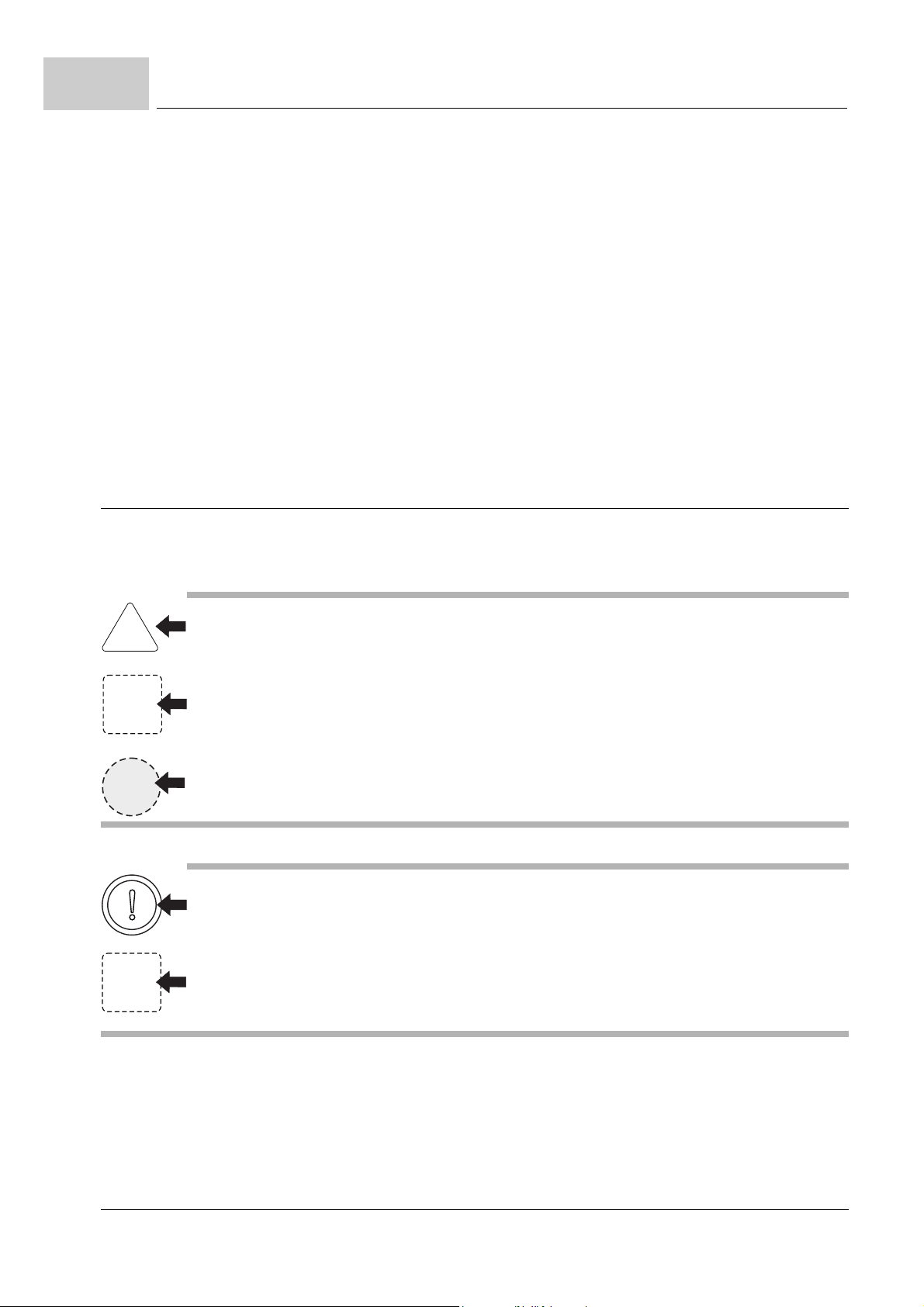
Each hazard is classified in one of three different hazard classes. Every hazard class
has one of the following characteristic signal words:
DANGER
m
serious property damage m serious personal injury m death -
will
occur
WARNING
m
serious property damage m serious personal injury m death -
CAUTION
m
minor to medium personal injury or
m
environmental pollution or
m
property damage -
2.1.1 Hazard information structure
The following two examples show you how the hazard informations are constructed. The
triangle is used when indicating a hazard for human beings. When there is a circle instead
of the triangle, the hazard information is only for possible property damage.
A triangle indicates hazard for human beings.
The shade of grey of the outline reflects the severity of the hazard - darker grey means rising
hazard.
The icon within the square illustrates the hazard.
The outline´s shade of grey reflects the severity of the hazard - darker grey means rising hazard. (Not every hazard information has a square representing the hazard, so we have shown
it as draft here)
The icon in the circle represents a command.
(Not every hazard information has a circle representing the hazard, so we have shown it as
draft here)
may
occur
occur
may
12
of 118
The circle indicates hazard for property.
The icon within the square illustrates the hazard.
The outline´s shade of grey reflects the severity of the hazard - darker grey means rising hazard. (Not every hazard information has a square representing the hazard, so we have shown
it as draft here)
Manual Single Power Unit BUM64S/A/F
Document no.: 5.01056.03 Baumüller Nürnberg Electronic GmbH & Co. KG
Page 13
Fundamental security information
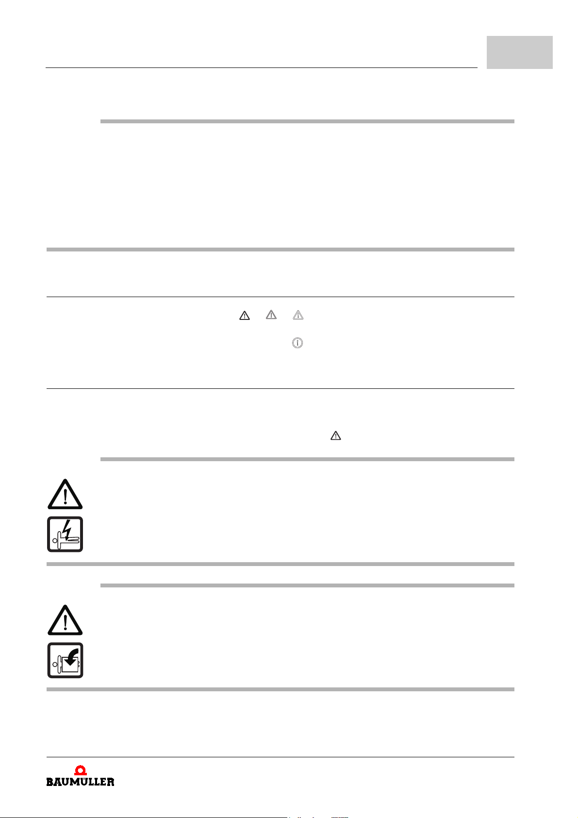
The text beneath the icons is constructed as follows:
HERE STANDS THE SIGNAL WORD WHICH INDICATES THE DEGREE OF THE HAZARD
Here we tell if one or more of the consequences described lower will occur if this hazard information is not observed.
m
here we describe the possible consequences. The worst consequence stands on the right
side.
Here we describe the hazard.
Here we describe what you can do to avoid this hazard.
2.1.2 Form of the hazard sign (triangular or round)
If there is a triangle like or or in front of the signal word, the hazard information
is referring to personal damage.
If there is a round hazard signal like in front of the signal word, the hazard information
is referring to property damage.
2
2.1.2.1 Hazard information on personal injury
To distinguish each class of hazard information, we use a characteristic outline for both
the triangular hazard signs and the square-form icons
For the hazard class
this hazard class we use in this documentation is listed below:
DANGER
The following
m
serious personal injury m death
The hazard is: electricity. Here the hazard may be described in detail.
Here we describe what you can do to avoid the hazard.
DANGER
The following
m
serious personal injury m death
The hazard is: mechanical influence. Here the hazard may be described in detail.
Here we describe what you can do to avoid the hazard.
will occur,
will occur,
DANGER
if you do not observe this danger information:
if you do not observe this danger information:
we use the danger sign. The hazard information of
Manual Single Power Unit BUM64S/A/F
Document no.: 5.01056.03
13
of 118
Page 14
2.1
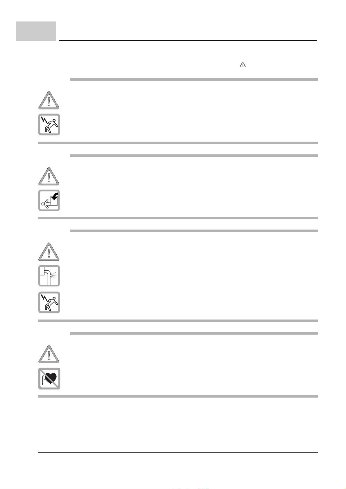
Hazard information and commands
For the hazard class
mation of this hazard class we will use in this documentation.
WARNING
The following
m
serious personal injury m death
The hazard is: electricity. Here the hazard may be described in detail.
Here we describe what you can do to avoid the hazard.
WARNING
The following
m
serious personal injury m death
The hazard is: mechanical influence. Here the hazard may be described in detail.
Here we describe what you can do to avoid the hazard.
may occur,
may occur,
WARNING
if you do not observe this warning information:
if you do not observe this warning information:
we use the warning sign . The following hazard infor-
WARNING
The following
m
serious personal injury m death
The hazard is: electro-conductive liquid together with electricity. Here the hazard may be
described in detail.
Here we describe what you can do to avoid the hazard.
WARNING
The following
m
serious personal injury m death
The hazard is: electro-magnetic radiation. Here the hazard may be described in detail.
Here we describe what you can do to avoid the hazard.
may occur,
may occur,
if you do not observe this warning information:
if you do not observe this warning information:
14
of 118
Manual Single Power Unit BUM64S/A/F
Document no.: 5.01056.03 Baumüller Nürnberg Electronic GmbH & Co. KG
Page 15
Fundamental security information
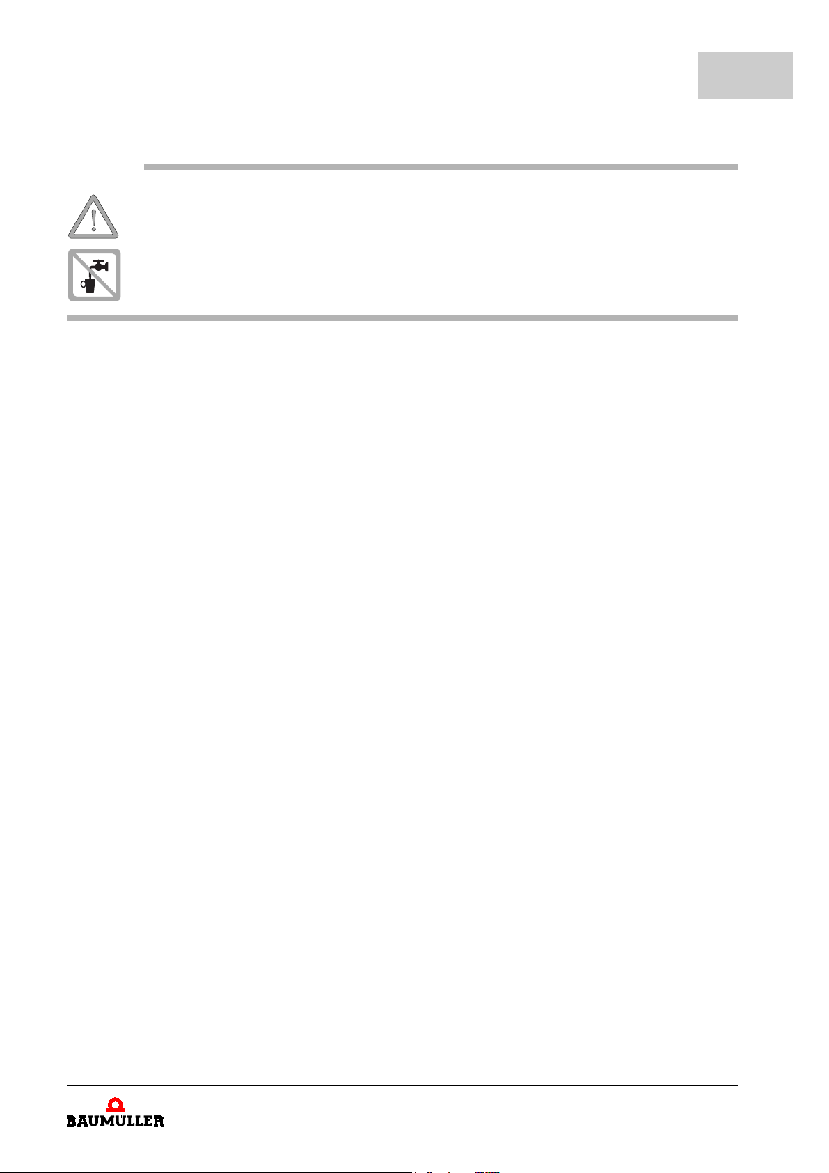
WARNING
The following
m
serious personal injury m death
The hazard is: liquid coolant. Here the hazard may be described in detail.
Here we describe what you can do to avoid the hazard.
may occur,
if you do not observe this warning information:
2
Manual Single Power Unit BUM64S/A/F
Document no.: 5.01056.03
15
of 118
Page 16
2.1
Hazard information and commands
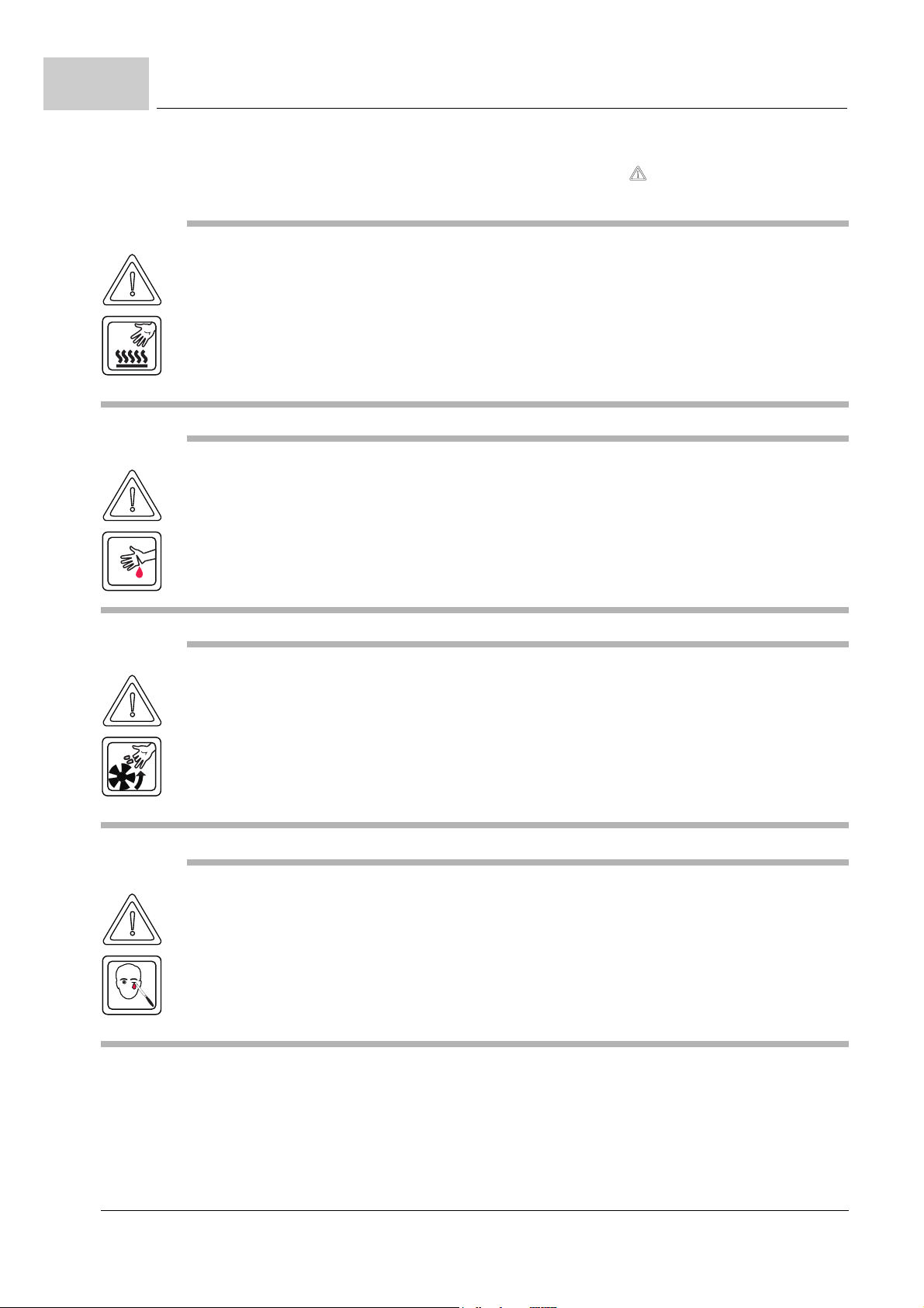
For the hazard class
sons or of environmental pollution. The following hazard information of this hazard class
we will use in this documentation.
CAUTION
The following
m
minor to medium personal injury.
The hazard is: hot surface. Here the hazard may be described in detail.
Here we describe what you can do to avoid the hazard.
CAUTION
The following
m
minor to medium personal injury.
The hazard is: sharp edges. Here the hazard may be described in detail.
Here we describe what you can do to avoid the hazard.
may occur,
may occur,
CAUTION
if you do not observe this caution information:
if you do not observe this caution information:
we use the caution sign when there is hazard for per-
CAUTION
The following
m
minor to medium personal injury.
The hazard is: rotating parts. Here the hazard may be described in detail.
Here we describe what you can do to avoid the hazard.
CAUTION
The following
m
minor to medium personal injury.
The hazard is: injury of the eye caused by ricochetting particles. Here the hazard may be
described in detail.
Here we describe what you can do to avoid the hazard.
may occur,
may occur,
if you do not observe this caution information:
if you do not observe this caution information:
16
of 118
Manual Single Power Unit BUM64S/A/F
Document no.: 5.01056.03 Baumüller Nürnberg Electronic GmbH & Co. KG
Page 17
Fundamental security information
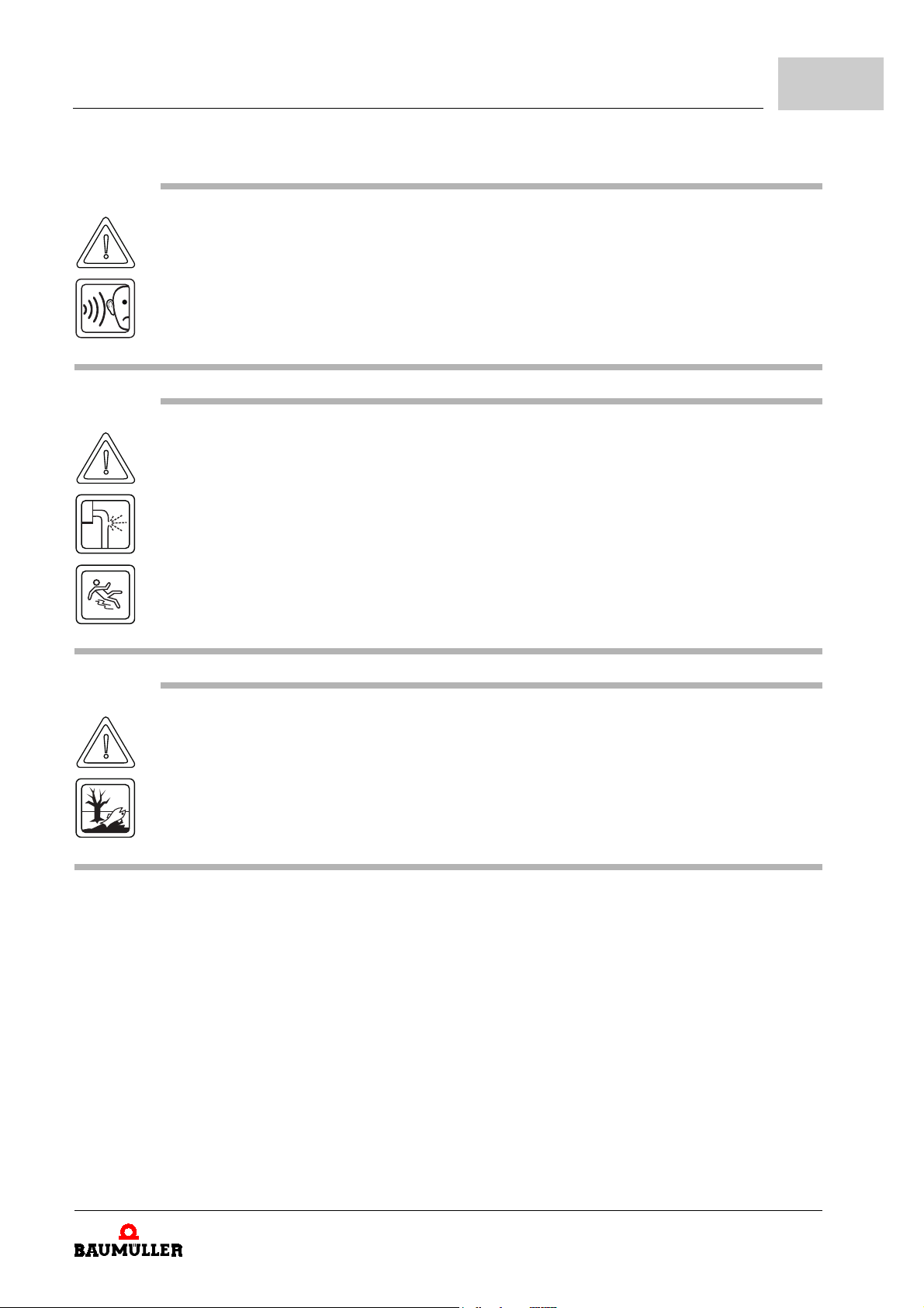
CAUTION
The following
m
minor to medium personal injury.
The hazard is: noise. Here the hazard may be described in detail.
Here we describe what you can do to avoid the hazard.
CAUTION
The following
m
minor to medium personal injury.
The hazard is: hazard of sliding caused by liquid. Here the hazard may be described in detail.
Here we describe what you can do to avoid the hazard.
may occur,
may occur,
if you do not observe this caution information:
if you do not observe this caution information:
2
CAUTION
The following
m
environmental pollution.
The hazard is: unadequate disposal. Here the hazard may be described in detail.
Here we describe what you can do to avoid the hazard.
may occur,
if you do not observe this danger information:
Manual Single Power Unit BUM64S/A/F
Document no.: 5.01056.03
17
of 118
Page 18
2.1
2.1.2.2 Hazard information on property damage
Hazard information and commands
If there is a round caution sign in front of the signal word, the safety information refers
to property damage.
CAUTION
The following
m
property damage.
The hazard is: electro-static discharge. Here the hazard may be described in detail.
Here we describe what you can do to avoid the hazard.
CAUTION
The following
m
property damage.
The hazard is: damage of the coolant hose. Here the hazard may be described in detail.
may occur,
may occur,
if you do not observe this caution information:
if you do not observe this caution information:
Here we describe what you can do to avoid the hazard.
2.1.2.3 Command signs used
carry safety gloves
carry safety shoes
carry eye protection
carry ear protection
18
of 118
Use this fire extinguishing agent:
ABC powder.
Manual Single Power Unit BUM64S/A/F
Document no.: 5.01056.03 Baumüller Nürnberg Electronic GmbH & Co. KG
Page 19
Fundamental security information
2.2 Information sign
NOTE
This note is a very important information.
2.3 Application according to the terms
You must always use this appliance properly. Listed below you will find some important
information. The information given is intended to give you some impression on how to op
erate this appliance according to the terms. The information below is not a complete list;
you must always observe the information given throughout this documentation.
m
project this application in a way, that the appliance is run within its specifications.
m
take care that only qualified personnel is working with or at this appliance.
m
mount this appliance only at a reasonable steady wall.
m
install this appliance according to the way shown in this documentation.
m
take care that the power supply always meets the requested specifications.
m
operate this appliance only if it is in a correct technical state.
m
operate this appliance always in an environment according to the information given in
the “Technical specifications“.
m
operate this appliance always in the regular condition.
For safety reasons you are not allowed to reconstruct this appliance.
m
observe all respective information given if you want to store this appliance.
2
-
You are using this appliance according to the terms, if you observe all notes and information given in this operating manual.
2.4 Non-appropriate application
Listed below you will find some examples of non-appropriate application. The information
below is intended to give you some impression of what non-appropriate application is.
However we cannot state all possible non-appropriate applications here. All applications,
where the notes and information given in this documentation is disregarded, are non-ap
propriate and therefore forbidden.
Examples:
m
you have disregarded the information given in this manual
m
you have used this appliance within a non-appropriate application
n
this appliance you have
m
unskillfully mounted
m
unskillfully connected
m
unskillfully commissioned
m
unskillfully operated
-
Manual Single Power Unit BUM64S/A/F
Document no.: 5.01056.03
19
of 118
Page 20
2.5
Education of the personnel
m
unskillfully or not maintained
m
let be mounted, connected, commissioned, operated and/or maintained by not or
not adequate qualified personnel
m
overloaded
n
operated it with
m
defective security devices
m
not properly mounted or without security devices
m
not efficient safety- and protection devices
m
environmental conditions being not within the specified values
m
you have reconstructed this appliance without written permission of Baumüller Nürnberg Electronic GmbH & Co. KG.
m
you have disregarded instructions concerning maintenance in the component manuals
m
you have failed to monitor parts of wear and tear properly
m
you have carried out a repair job unskillfully
m
you have unskillfully combined the appliance with products of other manufacturers
m
you have combined the drive system with defective and/or incorrectly documented
products of other manufacturers
2.5 Education of the personnel
The appliances of Baumüller Nürnberg Electronic GmbH & Co. KG are only to be
mounted, installed, operated and maintained by qualified personnel.
Qualified
personnel
Qualified personnel are persons who have been authorized by the plant manager to carry
out the activities required, who are able to recognize possible dangers and to avoid them.
They must have the skills, experience, instruction and knowledge of the operational con
ditions and the respective standards, regulations and rules to detect and avoid accidents.
2.6 Reconstructing the appliance
Unauthorized reconstructions without written permission of Baumüller Nürnberg Electronic GmbH & Co. KG are not allowed.
2.7 Disposal of the appliance
The correct disposal of the appliance is described in
ZDisposal– from page 79
-
.
20
of 118
Manual Single Power Unit BUM64S/A/F
Document no.: 5.01056.03 Baumüller Nürnberg Electronic GmbH & Co. KG
Page 21
2.8 Fire fighting
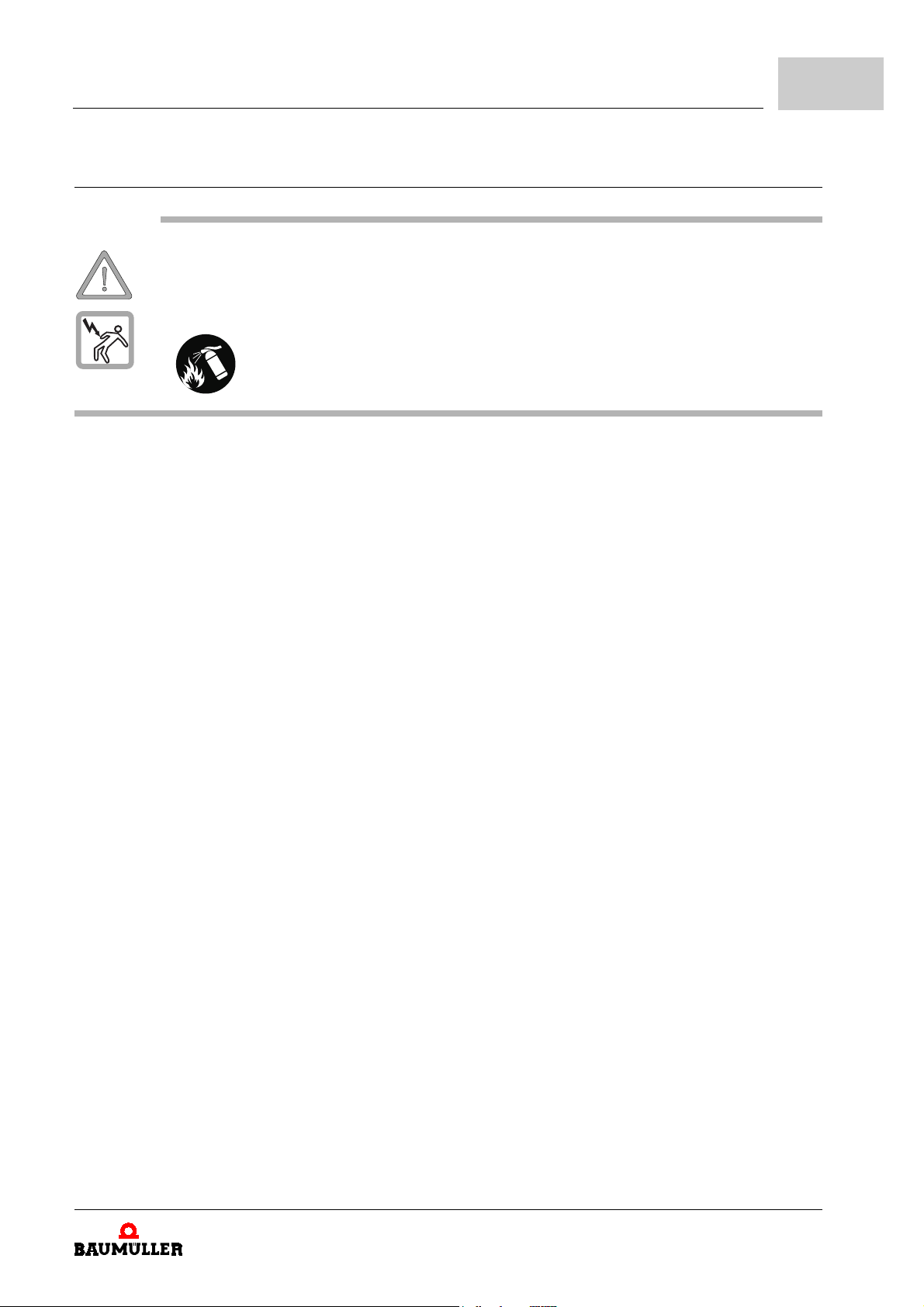
WARNING
The following
m
serious personal injury m death
The hazard is: electricity when using a conductive fire extinguishing medium.
Fundamental security information
may occur,
Use this fire extinguishing agent:
if you do not observe this warning information:
2
ABC powder / CO
2
Manual Single Power Unit BUM64S/A/F
Document no.: 5.01056.03
21
of 118
Page 22

2.8
Fire fighting
22
of 118
Manual Single Power Unit BUM64S/A/F
Document no.: 5.01056.03 Baumüller Nürnberg Electronic GmbH & Co. KG
Page 23

3
3.1 Transport
3.2 Unpacking
3P
ACKING AND
Every Baumüller appliance we have packaged before shipping in a way, that makes becoming damaged while on transport very unlikely.
The units are packed at the factory in accordance with the order.
h
avoid heavy shaking while on transport and severe bumping, e.g. when lowering, of the
unit.
After delivery of the (still packaged) item:
h
check if there are visible transportation damages!
if yes:
h
report this to your deliverer. Request a written confirmation of your reclamation and
make immediate contact with your local Baumüller Nürnberg Electronic GmbH
representative.
if there is no transportation damage visible:
T
RANSPORT
& Co.
h
open the packaging of the appliance.
h
check the scope of delivery according to the delivery note.
The scope of delivery is:
m
Produkt
m
these operating instructions including declaration of conformity/Declaration by manufacturer
m
supplement and fixing material
h
report a reclamation at your local Baumüller representative if the scope of delivery is
incomplete or if there is a transportation damage.
Manual Single Power Unit BUM64S/A/F
Document no.: 5.01056.03
23
of 118
Page 24

3.3
Disposal of the packaging
WARNING
The following
m
serious personal injury m death
The hazard is: electricity.
Do not operate the appliance if you have detected or suppose a transportation damage.
In this case please contact Baumüller Nürnberg Electronic GmbH & Co. immediately.
may occur,
3.3 Disposal of the packaging
The packaging consists of cardboard, plastics, metal pieces, corrugated cardboard and/
or wood.
h
observe the local regulations of disposal if you dispose the packaging.
if you do not observe this warning information:
3.4 Transportation precautions
For the first transport the appliance has been packaged by the manufacturer. If you intend
to transport the appliance yourself, make sure that the following conditions are kept
throughout the whole transport:
m
2 K 3 (environmental class)
m
- 30 °C to + 70 °C (temperature interval)
m
max. 1 g (vibration, shock, continuous shock)
24
of 118
Manual Single Power Unit BUM64S/A/F
Document no.: 5.01056.03 Baumüller Nürnberg Electronic GmbH & Co. KG
Page 25
4
4D
ESCRIPTION OF THE UNIT
This appliance is a power converter for the range of power up to 150 kW. This unit converts power taken from the mains network (mains-side supply unit) and supplies the electrical motor connected to it with the converted power (motor-side power unit). For control
only Baumüller Nürnberg Electronic GmbH & Co. KG rack type controllers can be used.
m
BUS 6 V-controller
m
BUS 6 M-controller
For the controller there is a separate description with the respective features and technical specifications available.
Depending on the controller used, you can drive either asynchronous or even synchronous motors equipped with different encoder systems at the BUM64S/A/F single power
units.
NOTE
Do not use this appliance in populated areas (see EN 61800-3, 6.4.2.1), because this unit
may cause high frequency interference.
Manual Single Power Unit BUM64S/A/F
Document no.: 5.01056.03
25
of 118
Page 26
4.1
Variants
4.1 Variants
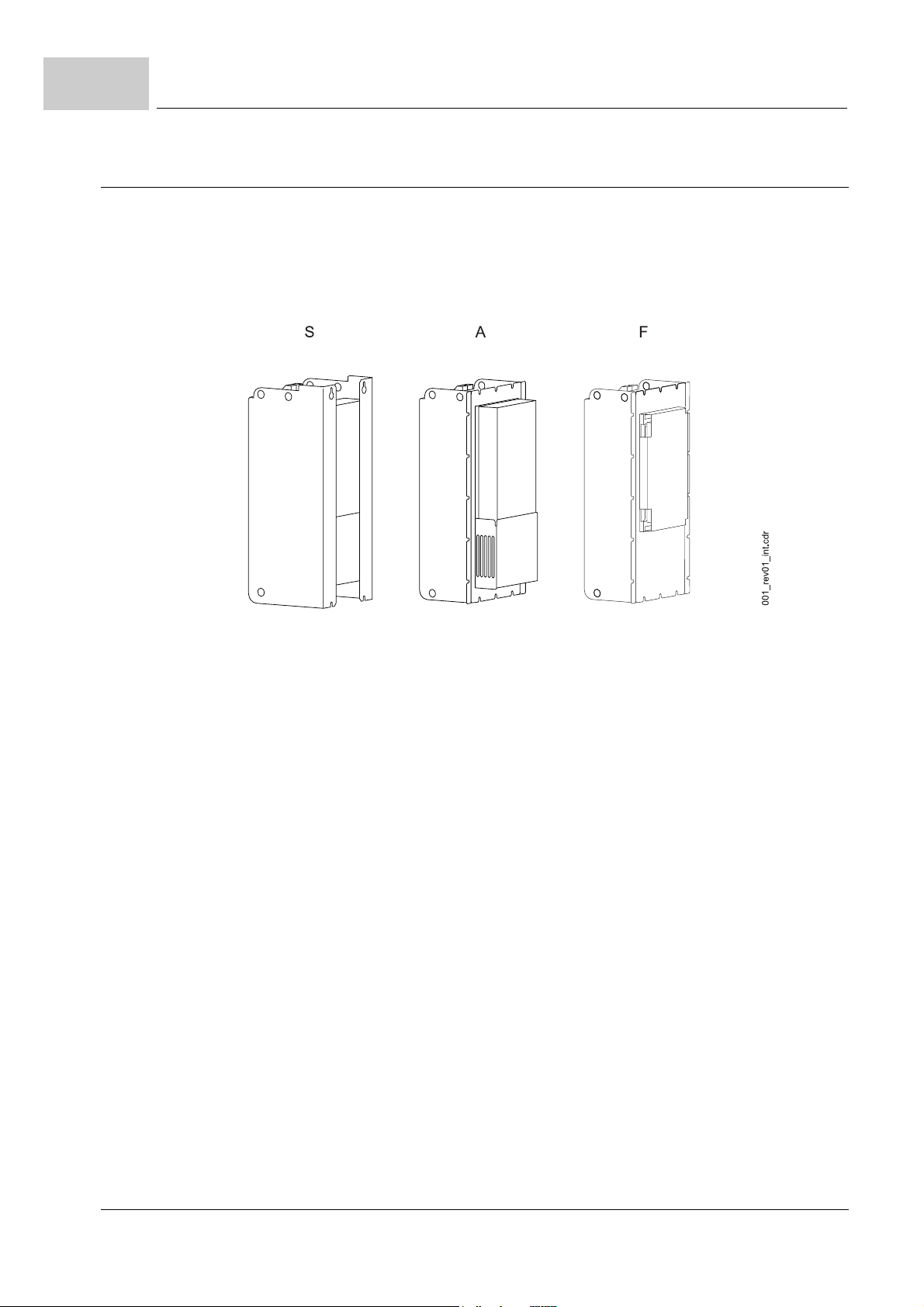
The BUM64S/A/F single power units are available in 3 variants, which differ in power (T)
or in the cooling version (S/A/F):
stands for Switching cabinet variant (air ventilation inside the switching cabinet)
m
S
stands for window mounting variant (Air ventilation outside the switching cabinet)
A
m
stands for window mounting variant (water cooler outside the switching cabinet)
F
figure 1: Cooling variants
26
of 118
Manual Single Power Unit BUM64S/A/F
Document no.: 5.01056.03 Baumüller Nürnberg Electronic GmbH & Co. KG
Page 27
4.2 Overview of hazardous areas
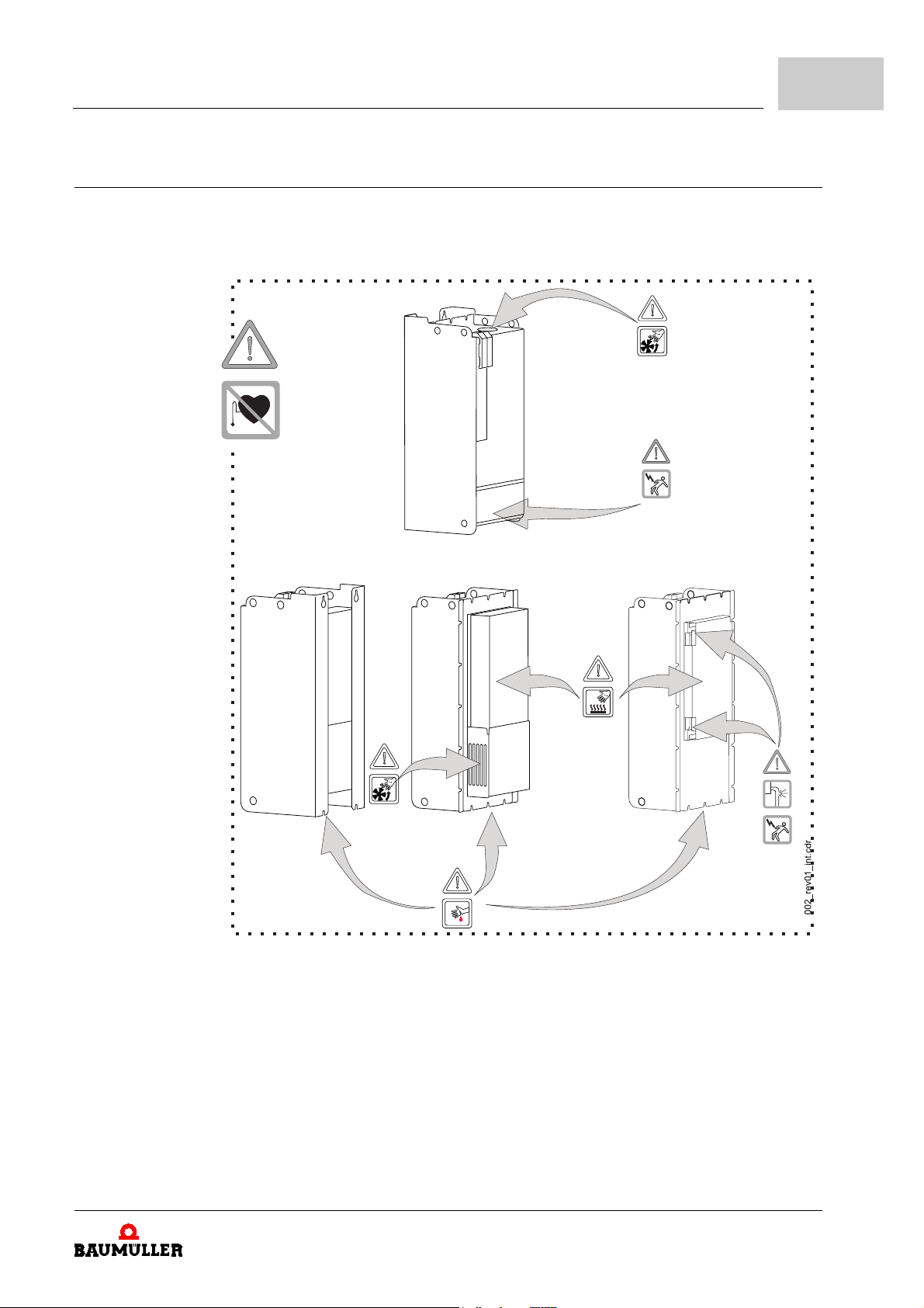
The following figure shows the hazardous areas at each respective appliance. Use this
overview to get informed about the existing hazardous areas when you learn to get famil
iar with this appliance.
Description of the unit
4
-
figure 2: Hazardous areas
Manual Single Power Unit BUM64S/A/F
Document no.: 5.01056.03
27
of 118
Page 28
4.3
Characteristics of the unit - type key
4.3 Characteristics of the unit - type key
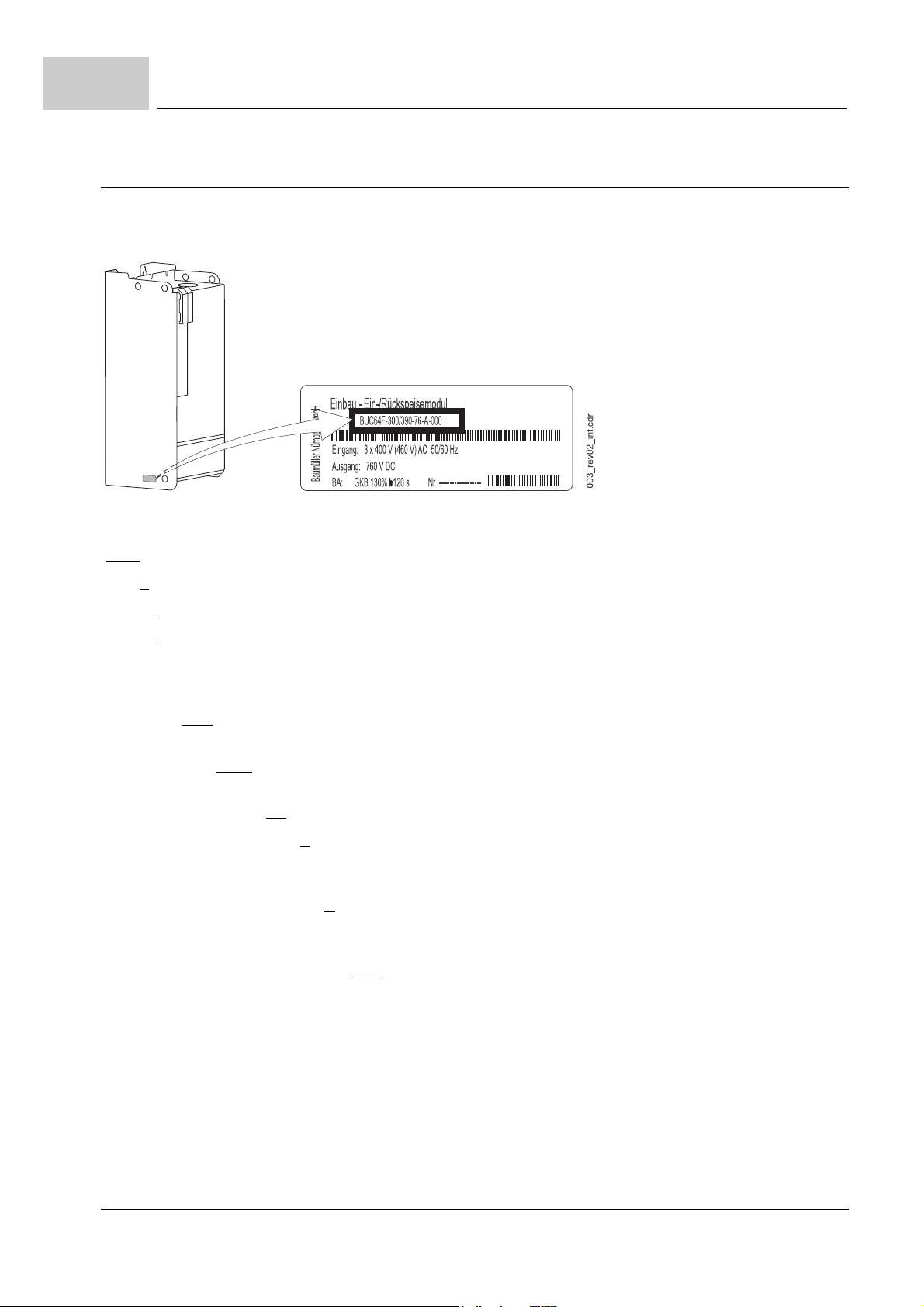
On the type shield (positioned on the inner side, see figure below) you will find the type
key and the serial number of the appliance.
figure 3: type shield with type key
BUM63X - XXX/X XX - XX - X - X - XXX Baumüller converter single power unit
BUM63X - XXX/X XX - XX - X - X - XXX Type
BUM63X - XXX/X XX - XX - X - X - XXX Size
BUM63X - XXX/X XX - XX - X - X - XXX Cooling variant
S: air ventilation with intake and outlet inside the switching cabinet
A: air ventilation with intake and outlet outside the switching cabinet
F: water-cooled with water cooler outside the switching cabinet
BUM63X - XXX/X XX - XX - X - X - XXX Output rated current in ampere at 40° C environmental- and cool-
ant temperature and 4 kHz cycle frequency
BUM63X - XXX/X XX - XX - X - X - XXX Output peak current in ampere at 40° C environmental- and cool-
ant temperature and 4 kHz cycle frequency, t ≤ 120 s.
BUM63X - XXX/X XX - XX - X - X - XXX Rated DC link voltage x 10 [V]
BUM63X - XXX/X XX - XX - X - X - XXX Ballast
O: without ballast circuit
E: with ballast circuit, external resistor
BUM63X - XXX/X XX - XX - X - X - XXX Safety relay
O: without safety relay
M: with safety relay
BUM63X - XXX/X XX - XX - X - X - XXX Stage of development / model
On the type key you will find only a part of the technical specifications. An overview of all
technical specifications you will find in ZAppendix D - Technical specifications– from
page 97.
28
of 118
Manual Single Power Unit BUM64S/A/F
Document no.: 5.01056.03 Baumüller Nürnberg Electronic GmbH & Co. KG
Page 29
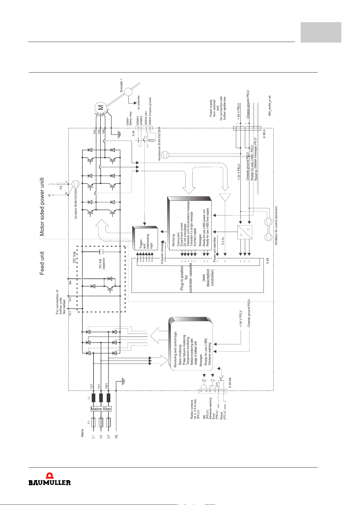
4.4 Block switching diagram
Description of the unit
4
figure 4: Block switching diagram BUM 64S/A/F
Manual Single Power Unit BUM64S/A/F
Document no.: 5.01056.03
29
of 118
Page 30

4.4
Block switching diagram
30
of 118
Manual Single Power Unit BUM64S/A/F
Document no.: 5.01056.03 Baumüller Nürnberg Electronic GmbH & Co. KG
Page 31
If you intend to mount the appliances within closed electrical work shops according to EN
50178/ VDE 0160, section 5.2.7, you will in addition have to take care of extra messages
so you meet the requirements of EN 50178/VDE 0160, section 5.2.4 and EN 60204-1/
VDE 0113 part 1, section 6.2.2.
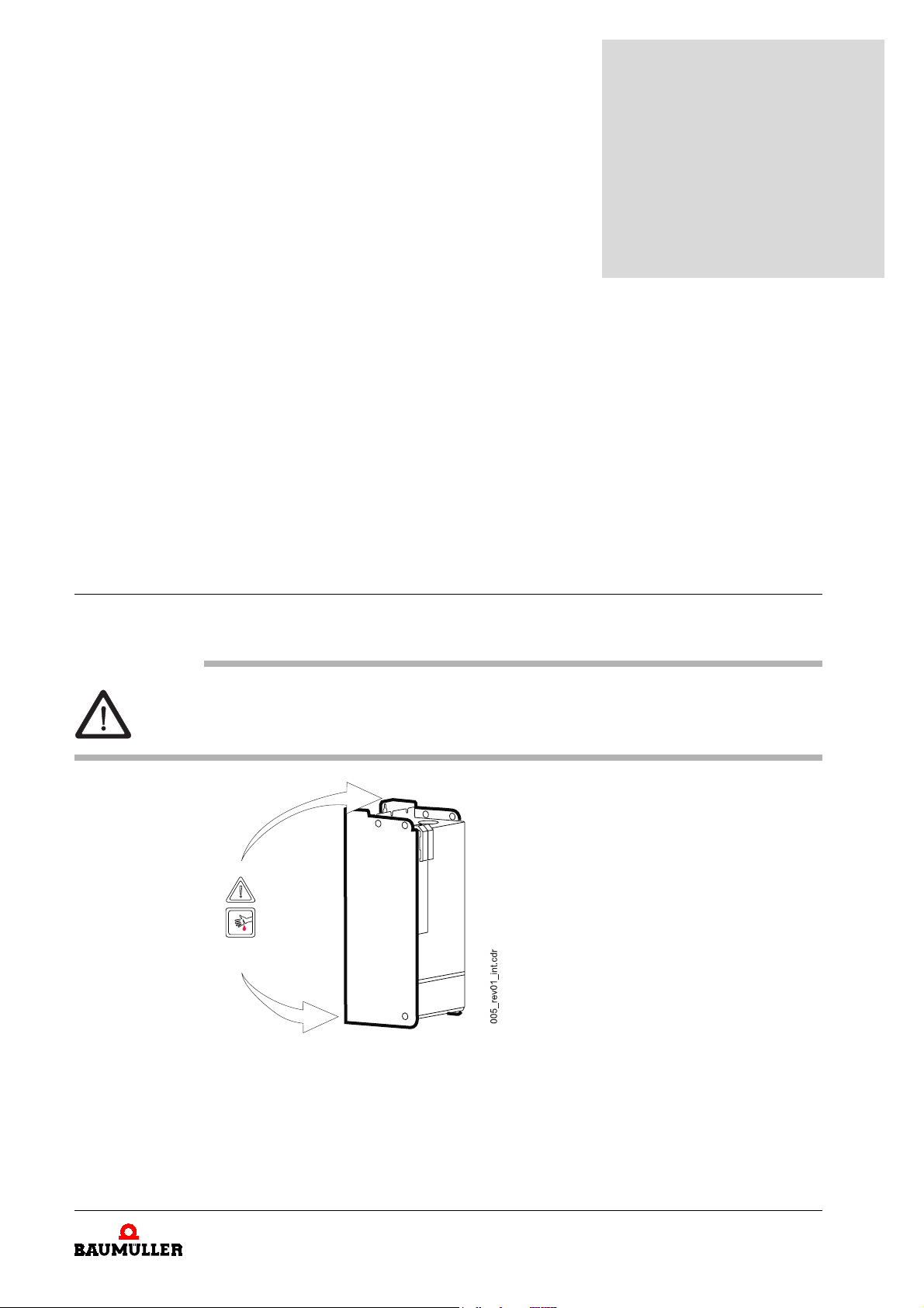
5.1 Hazardous areas during mounting
The following overview shows you the hazardous areas at the appliance which are important for mounting.
Use this overview for the mechanical mounting only. Hazards which are caused by
electricity are not shown here. Hazards caused by electricity you will find under
ZHazardous areas at installation– on page 43
5
5M
OUNTING
.
figure 5: Hazardous areas during mounting
Manual Single Power Unit BUM64S/A/F
Document no.: 5.01056.03
31
of 118
Page 32
5.2
Mounting steps
5.2 Mounting steps
The mechanical mounting consists of the following steps:
m
select the switching cabinet.
m
produce the drill holes/threaded holes and the cut-out (variant A/F only).
m
mount the unit.
m
connect the coolant circulation (variant F only), test the tightness and perform a pressure test.
Further information concerning the single steps are given in the following sections.
5.2.1 Select a switching cabinet
BUM64S/A/F units are build-in appliances with respect to EN 50178/VDE 0160
section
meet the minimum requirements regarding the protection class stated in EN 50178/VDE
0160, section 5.2.4 (IP 2X, eventually also IP4X acc. to EN 60529/5.1).
WARNING
The following
m
serious personal injury m death
The hazard is: mechanical influence. The units weigh depending on the model between 65
and 88 kilograms.
5.2.6. They are intended for mounting into ordinary switching cabinets, which
may occur,
if you do not observe this warning information:
select a switching cabinet, which can carry this weight permanently
NOTE
If you mount a window variant (F/A), the back side may only have a maximum thickness of
6 mm.
32
of 118
Manual Single Power Unit BUM64S/A/F
Document no.: 5.01056.03 Baumüller Nürnberg Electronic GmbH & Co. KG
Page 33
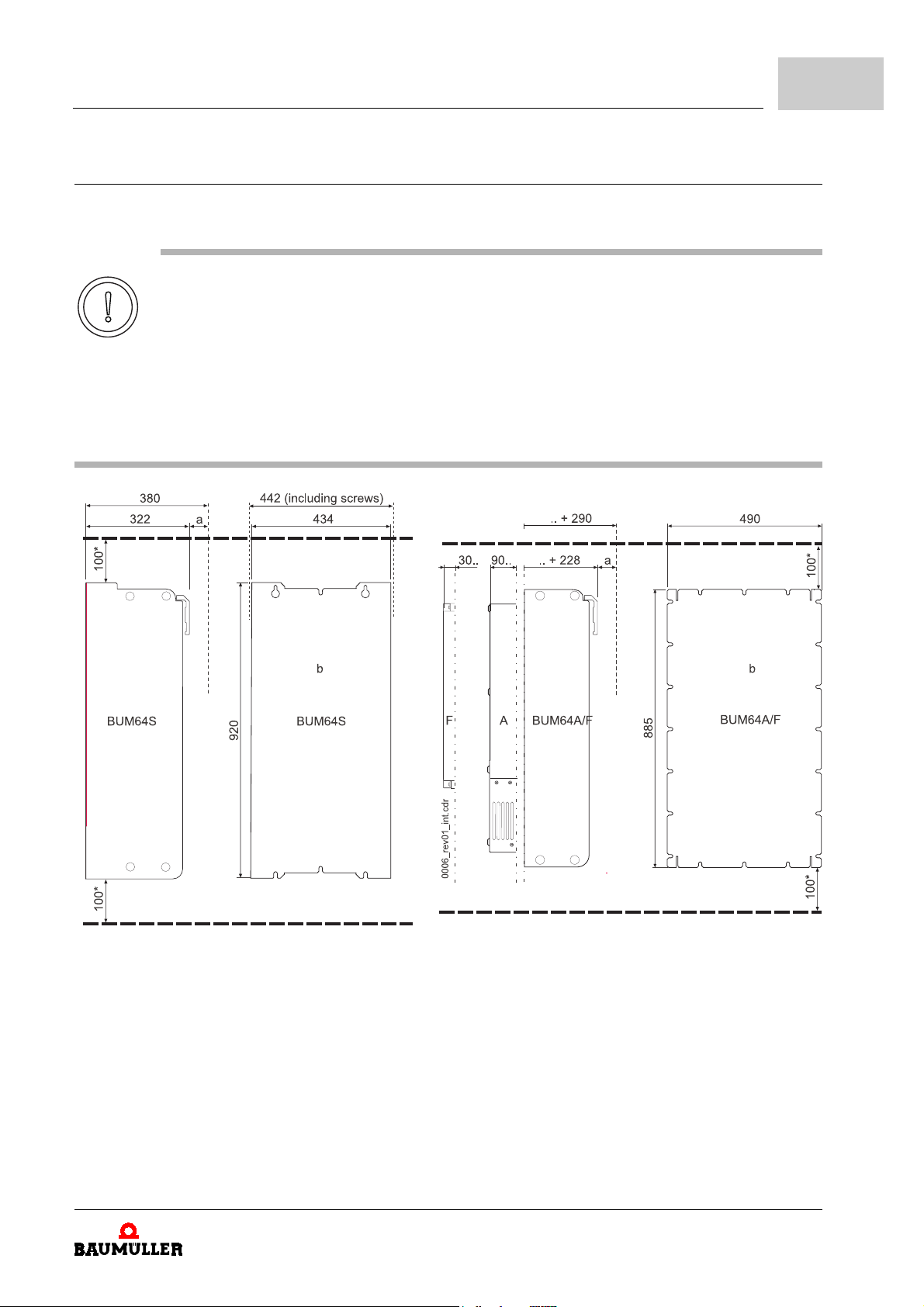
5.2.1.1 Space requirements - dimensional drawings
Use the following dimensional drawings to determine the space requirements in the
switching cabinet.
CAUTION
The following
m
property damage.
The hazard is: overheating of the appliance.
Take care of proper ventilation of the appliances exhaust air. Make sure that the coolant intake and outlet is not obstructed.
Observe the required coolant temperature and -amount (see
conditions– on page 99). If necessary mount additional ventilators to the switching cabinet.
may occur,
if you do not observe this caution information:
Mounting
ZD.2 Required environmental
5
figure 6: Dimensional drawing of BUM63(T)S/A/F/I
a: free space for controller, connector and cable
approx. 60 mm
b: back side view
*: free space
Manual Single Power Unit BUM64S/A/F
Document no.: 5.01056.03
33
of 118
Page 34
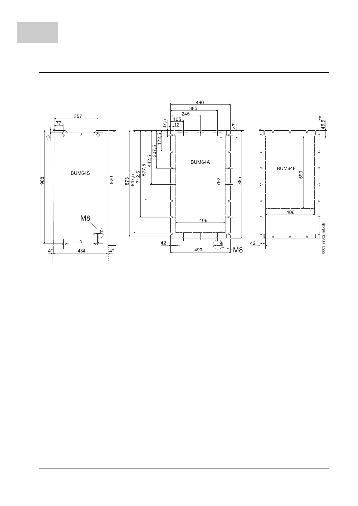
5.3
Producing the drill holes/threaded holes and the cut-out
5.3 Producing the drill holes/threaded holes and the cut-out
h
produce the drill holes/threaded holes (variant A/F only) according to the drilling figures
below.
* screw head
figure 7: Drilling figure of BUM64S/A/F
**all other dimensions see BUM64A
34
of 118
Manual Single Power Unit BUM64S/A/F
Document no.: 5.01056.03 Baumüller Nürnberg Electronic GmbH & Co. KG
Page 35
5.4 Mounting the unit
screw the back side of the unit to the rear wall of the switching cabinet.
1
mount all screws in order to secure EMC of the units.
2
5.4.1 BUM64S mounting
CAUTION
Mounting
5
The following
m
minor to medium personal injury.
The hazard is: sharp edges.
Keep the unit’s weight in mind - the appliance weighs at least 49 kg.
Lift the appliance only with suitable equipment and/or with the help of adequate qualified per-
sonnel.
may occur,
carry safety gloves
if you do not observe this caution information:
Manual Single Power Unit BUM64S/A/F
Document no.: 5.01056.03
35
of 118
Page 36
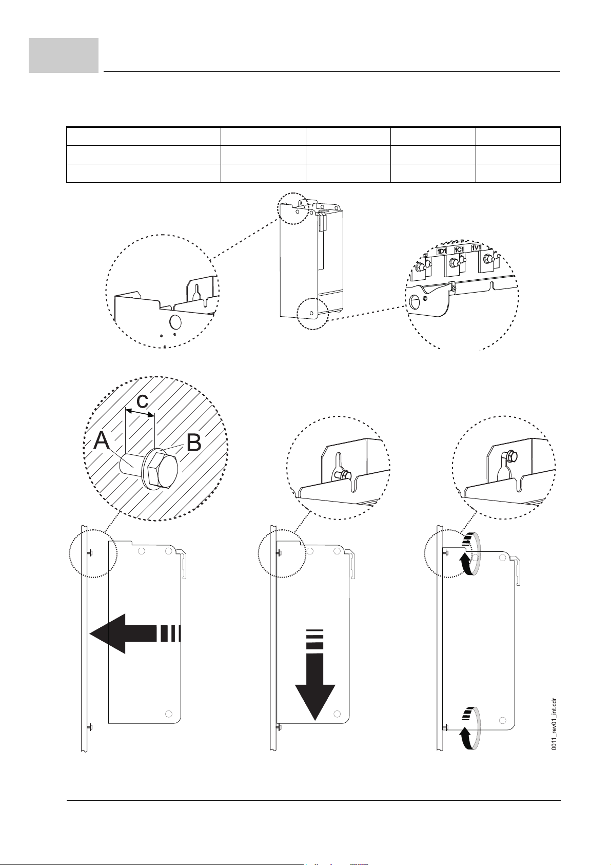
5.4
screws (A) 4 x M8
washers (B) 4 x (8.4 x 17)
mounting distance (c) c = 7 mm
Mounting the unit
figure 8: Mounting instruction BUM64S
36
of 118
Manual Single Power Unit BUM64S/A/F
Document no.: 5.01056.03 Baumüller Nürnberg Electronic GmbH & Co. KG
Page 37
5.4.2 Mounting BUM64 window variant A/F
CAUTION
The following
m
minor to medium personal injury.
The hazard is: sharp edges.
Keep the unit’s weight in mind - the appliance weighs 42 kg.
Lift the appliance only with suitable equipment and/or with the help of adequate qualified per-
sonnel.
WARNING
The following
m
serious personal injury m death
The hazard is: electrical conductive liquid in contact with electricity. When a water-
cooled appliance is ejecting coolant water, the water can invade through defective sealings
into the switching cabinet and make contact with parts which carry dangerous voltages.
may occur,
carry safety gloves
may occur,
if you do not observe this caution information:
if you do not observe this warning information:
Mounting
5
Make sure not to damage the sealing at the back side of the unit. Only mount the unit if the
sealing is not damaged.
Manual Single Power Unit BUM64S/A/F
Document no.: 5.01056.03
37
of 118
Page 38
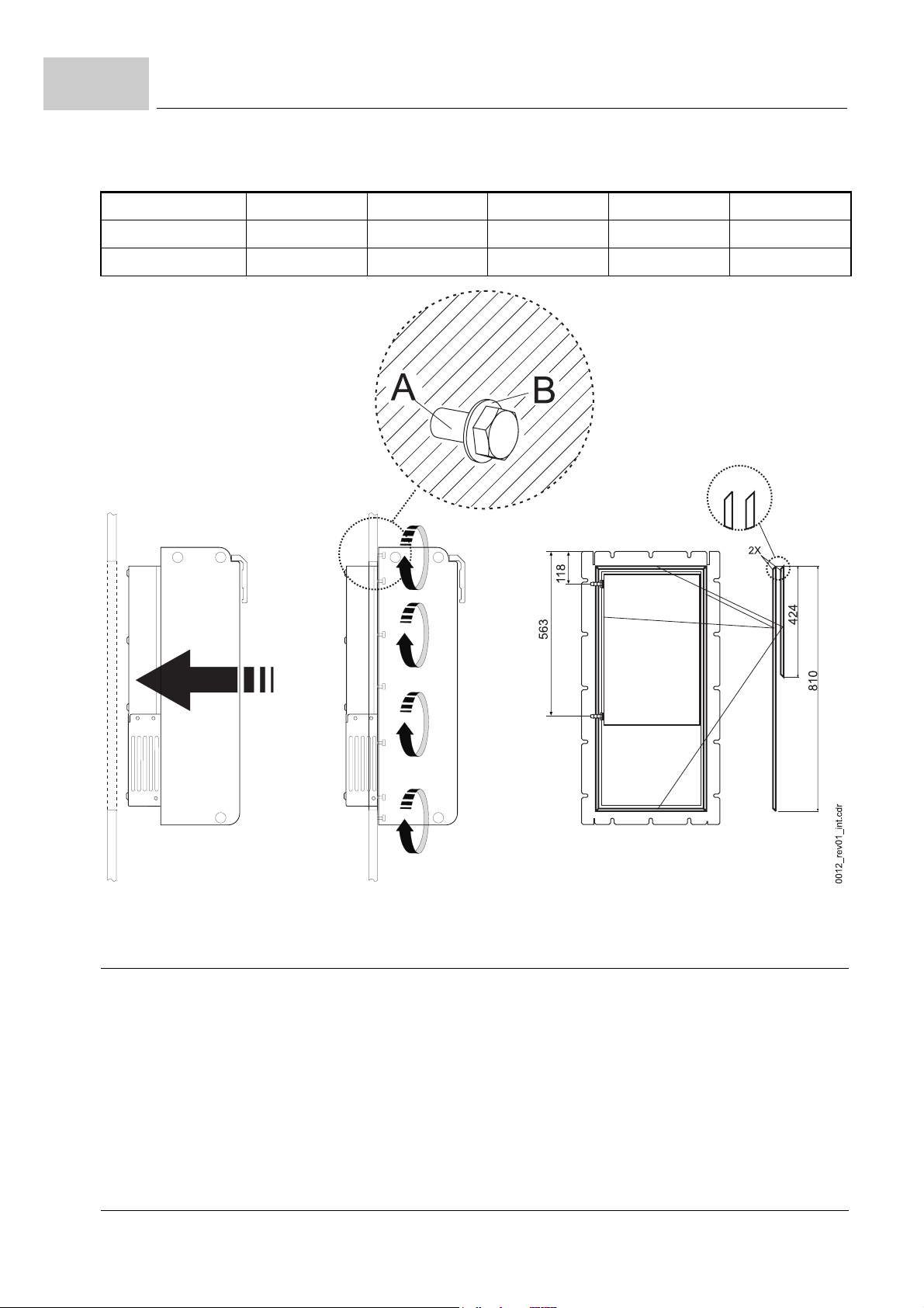
5.4
screws (A) 16 x M8
washers 16 x (8.4 x 17)
sealing see accessories
Mounting the unit
figure 9: Mounting instruction BUM64 window variant A/F
5.4.2.1 Coolant
The coolant must meet certain requirements. The requirements the coolant must have
you will find in ZD.2 Required environmental conditions– on page 99
38
of 118
Manual Single Power Unit BUM64S/A/F
Document no.: 5.01056.03 Baumüller Nürnberg Electronic GmbH & Co. KG
.
Page 39
Mounting
WARNING
The following
m
serious personal injury m death
The hazard is: electrical conductive liquid in contact with electricity. The heatsink can
corrode and become leaky if the wrong coolant is used. When e.g. the heatsink is leaky, the
cooling water can emerge the coolant circulation, invade into the switching cabinet and make
contact with parts which carry dangerous voltages.
Do not mix anticorrosives!
Under all circumstances keep the mixture ratio and test the mixture ratio within the stated
maintenance intervals (see
Observe the security information supplied by the anticorrosive manufacturer and the security
data sheets according to EU-guideline 91/155/EWG or respective common national guide
lines of the country where the appliance is in operation.
may occur,
if you do not observe this warning information:
ZInspection interval– from page 73
).
5
-
For disposal of the coolant observe the water endangerment classes (WGK) supplied by
the manufacturer. Since May 17
man regulation about water endangering substances). Beginning from class 1 (weak endangering water, Germany) the water endangering rises with the number. In any case the
disposal has to be carried out according to the regulations. The local waste water admin
istration must be consulted. A disposal into the sewer - even thinned - is not allowed.
CAUTION
The following
m
property damage.
The hazard is: Damage of the coolant circulation.
Do not use coolant lubricants from manufacturing processes as coolant!
Coolant circulations must be kept in a filled state using coolant-water mixtures in order to
avoid corrosion at the transition between liquid and air.
Make sure, that there are no air reservoirs within the coolant circulation.
Remainders of coolant can act corrosive, lead to a lowering of the pH-value and act corrosive
within the acid pH-value sector.
When exchanging or switching over from one coolant to another observe that the coolant circulation must be thoroughly rinsed with water several times.
If coolant circulations that have been filled with a coolant-water mixture must be emptied and
cannot be refilled within a few days, it is essential, that they are rinsed repeatedly with water
and after that be emptied completely.
may occur,
if you do not observe this caution information:
th
1999 there is no more class 0 within the VwVwS (Ger-
-
Manual Single Power Unit BUM64S/A/F
Document no.: 5.01056.03
39
of 118
Page 40
5.4
5.4.2.2 Connecting BUM64F to coolant circulation
Mounting the unit
The BUM64F unit has a pre-mounted heatsink at its back. The topmost and the lowest
threaded hole (G1/8") in the heatsink are destined for the intake and outlet of a coolant
circulation system. For the connection to the customer side of the coolant circulation use
connectors with an outside thread G1/8". Onto these connectors the customers hoses for
intake and outlet can be fitted.
The BUM64F is mounted in a switching cabinet. The heatsink connections are then situated on the back side of the unit.
Mounting the heatsink connections:
supply suitable connectors (material: brass, G1/8“ outside thread)
1
clean the threaded holes and connectors
2
apply silicone sealant, e.g. Loctite 5331 onto a least one (clean!) thread winding.
3
The silicone sealant prevents either corrosion between the different construction materials and improves also the security/tightness.
turn the connectors by hand into the threaded holes of the heatsink and tighten them
4
with the maximum admissible torque.
CAUTION
The following
m
property damage.
The hazard is: damage of the connectors thread.
do not exceed the maximum torque (6 Nm) when you tighten the connectors.
5
6
NOTE
You can choose any direction of flow.
7
8
may occur,
connect the intake with one of the connectors.
connect the outlet with the other connector.
check the tightness of the coolant circulation.
perform a leak test with the required pressure (12 bar).
if you do not observe this caution information:
40
of 118
Manual Single Power Unit BUM64S/A/F
Document no.: 5.01056.03 Baumüller Nürnberg Electronic GmbH & Co. KG
Page 41

6
6I
NSTALLATION
In this chapter we describe the electrical installation of the appliance. About the mechanical mounting you have learned in
The steps for installation are:
find out and check the required specifications of the power supply. Make sure the
1
mains meets the requirements.
find out what electrical wiring is required and supply the respective cables.
2
find out the characteristics of the connections and configure the cables respectively.
3
follow the EMC guidelines when routing the cables.
4
Is the fastening to be carried out according to UL 508C? If “yes“, use a suitable torque
5
wrench (see
ZFastening according to UL– on page 60
ZMounting– from page 31
).
.
6.1 General hazard information
The BUM64S/A/F appliances are defined as working funds of protection class I in respect
of HD366 S1 chapter 3.2, see also EN 50178/VDE 0160 sect. 5.2.9.
Working funds of class I are characterized by the fact, that the protection against dangerous body currents not only comes from the basic insulation. Furthermore they are
equipped with additional safety precautions. This additional protection consists of the
housing and other parts being supplied with a protective earth connection. So in case the
basic insulation fails there is no risk of dangerous voltages. The insulation of the appli
ances is carried out across the total component at least in the basic insulation class according to EN 50178/VDE 0160, sect. 5.2.9.1. This applies to the insulation between
current circuits and the environment.
The control connections of the appliance are secure isolated from the mains network.
They are laid out for use of PELV-/SELV-circuits.
When determining the air- and creepage distances the following criteria have been considered:
m
Soiling grade 2 acc. to EN 50178/VDE 0160, sect. 5.2.15.2, table 2, line 3: Normally
only non-conducting pollutants are produced. When the units are out of service, brief
conductivity can occur due to condensation.
m
Overvoltage category III according to IEC 664-1, table 1 for the air clearances of mains
circuits to their environment according to EN 50178/VDE 0160, sect. 5.2.16.1.
-
Manual Single Power Unit BUM64S/A/F
Document no.: 5.01056.03
41
of 118
Page 42
6.1
General hazard information
m
Rated insulation voltage of the mains input circuits (TN- and TT- networks) is 849 V
according to EN 50178/VDE 0160, section 3.64.
Series BUM64S/A/F units are conditional short-circuit-proof in the sense of EN 50178/
VDE 0160, sect. 6.3.4.
During operation, the principles on which the power converter and the motor work lead to
leakage currents to earth occurring. These are to be conducted by use of the appropriate
protective conductors which may lead to a premature release of a series fault current cir
cuit breaker.
.
WARNING
The following
m
serious personal injury m death
may occur,
The hazard is: Electricity. When there is body contact or earth leakage a direct current component in the fault current can be generated. This may hinder or keep a fault current circuit
breaker from working properly.
Connecting the single power unit to mains input only by use of a fault current circuit breaker
is forbidden (EN 50178/VDE 0160, sections 5.2.11 and 5.3.2.1).
if you do not observe this warning information:
-
Protection against direct contact with the units is achieved by installing them in commercially available switching cabinets. Their degree of protection must meet at least the minimum requirements of EN 50178/VDE 0160, section 5.2.4 and EN 60204-1, chapter 12.4.
Plastic covers on the equipment provide additional protection against accidental contact
when commissioning or in case of casual use of control elements located close to the
equipment. For the power connection additional measures must be taken according to
IEC 60536-2, chapter 5.1.1, German accident prevention directive “Electrical plants and
working funds“ VBG4.
Essential for personal protection are the safety measures and security regulations according to DIN/VDE.
.
WARNING
The following
m
serious personal injury m death
may occur,
if you do not observe this warning information:
The hazard is: Electricity.
Missing protective conductor connections at the unit or at the motor can lead to personal damage.
Connect the protective conductors.
Discharging time of voltage conducting parts is > 1 min.
Before working at voltage conducting parts check with adequate test equipment that the parts
do no longer conduct voltage. Touch parts only after you have assured that they are voltage
free and after unit and motor have been secured against reactivation.
42
of 118
Manual Single Power Unit BUM64S/A/F
Document no.: 5.01056.03 Baumüller Nürnberg Electronic GmbH & Co. KG
Page 43
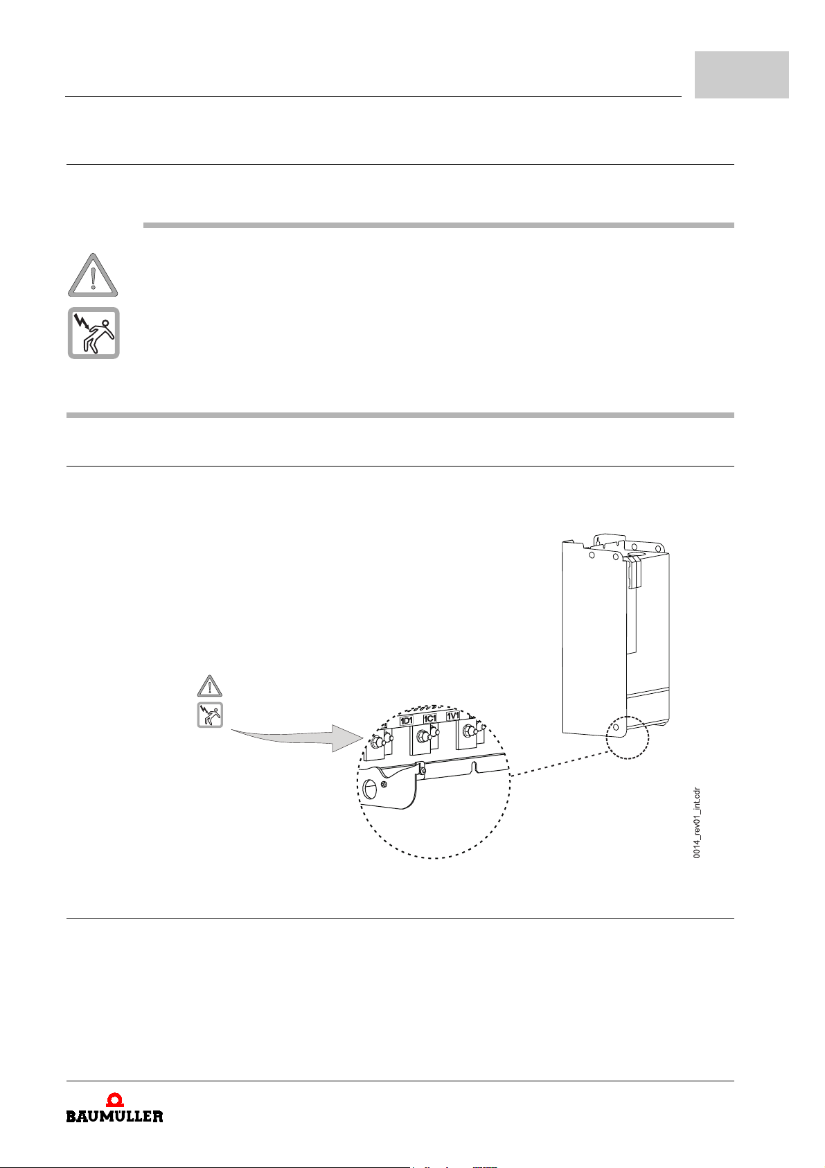
6.1.1 Voltage test
All of these Baumüller units have been voltage-tested according to EN 50178/VDE 0160,
section 9.4.5.
.
WARNING
The following
m
serious personal injury m death
The hazard is: Electricity.
Subsequent high voltage tests are to be carried out by Baumüller Nürnberg Electronic GmbH
& Co. KG only.
If you want to perform a high voltage test of the complete switching cabinet equipment without
the Baumüller-unit, you must first separate all cable connections from the Baumüller-unit.
may occur,
if you do not observe this warning information:
6.2 Hazardous areas at installation
Installation
6
The following overview shows all areas at the unit, which can de dangerous at he electrical installation.
6.3 Requirements on the electrical power network
The units are intended for the permanent supply connection to the common TN- and TTindustrial network in star connection with hard or low impedance earthed neutral point
according to IEC 364-4-41, chapter 413.1.3, chapter 413.1.4; they are intended for indus
trial networks with non- or high impedance earthed neutral point (IT-supply) and for industrial networks with hard or low impedance earthed corner point (earthed star delta supply)
with a line-to-line voltage from up to 3 x 480 Veff .
Manual Single Power Unit BUM64S/A/F
Document no.: 5.01056.03
-
43
of 118
Page 44
6.4
Cable requirements
In case UL 508 C is considered: the maximum short-circuit current of the supply may be
10000 A.
A listing of the requirements to the electrical supply is to be found in
on the power supply– on page 98.
h
Assure, that the existing supply fulfills all requirements.
6.4 Cable requirements
ZD.1 Requirements
In the technical specifications, see (
97) you will find all data, e.g. environmental conditions, electrical connection data and other which must be observed when choosing a cable. The BUM64S/A/F unit meets the UL
requirements, if you use the respective cables and if you carry out the fastening of the
cables accordingly.
NOTE
If UL508C is applied:
power connections with the correct torque, see also information given in
diagram– on page 58.
Further information you will find in the appendix under
appliance– on page 104,
ZCable from appliance to motor– on page 105
h
6.5 Connections
In the following we give you detailed information about the connections. A summary is
shown in the ZConnection diagram– on page 58
ZAppendix D - Technical specifications– from page
connect only 60 °C / 75 °C copper lines. Carry out the fastening of the
ZCable for control voltage supply / signals– on page 104
.
make sure that all cables used meet the requirements.
.
ZConnection
ZCable from mains supply to
and
44
of 118
Manual Single Power Unit BUM64S/A/F
Document no.: 5.01056.03 Baumüller Nürnberg Electronic GmbH & Co. KG
Page 45
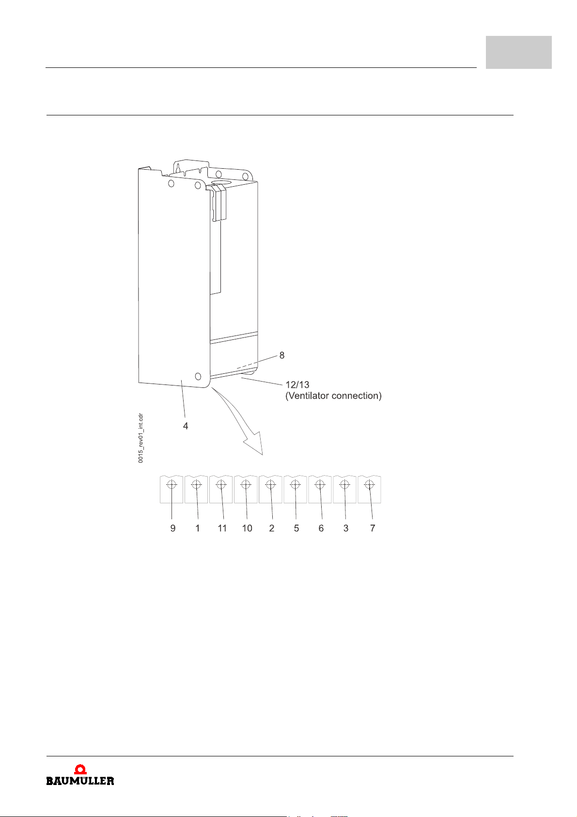
6.5.1 Power terminals
Installation
6
The power terminals are located at the bottom side of the unit (see
45).
Zfigure 10– on page
figure 10: Power terminals
Manual Single Power Unit BUM64S/A/F
Document no.: 5.01056.03
45
of 118
Page 46
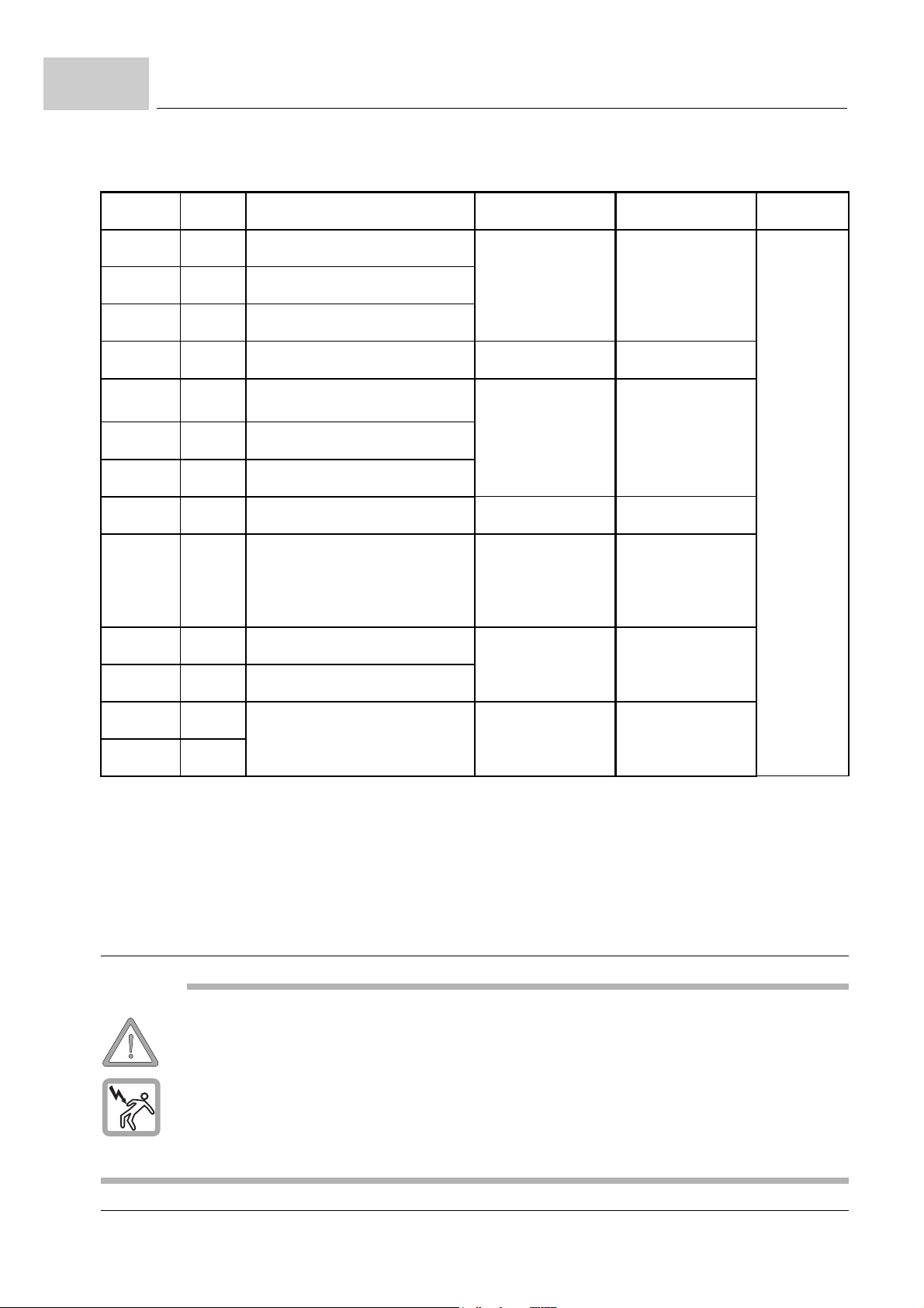
6.5
Connections
terminal pos.
1)
description
U
interval
1U2 1 U phase motor terminal 0 V (Û)
to
1V2 2 V phase motor terminal
830 V (Û)
1W2 3 W phase motor terminal
S
4 earth connection
1U1 5 L1 phase mains connection 360 V (UAC)
to
1V1 6 L2 phase mains connection
528 V (UAC)
1W1 7 L3 phase mains connection
S
Ba- 9 Ballast resistor connection
8 earth connection
Ba- is connected to the collector of the breaking switch
between
Ba+ and Ba-
0 to 830 V
Ba+ is 1C1
1C1 10 + DC link connection between
1C1 and 1D1
- DC link connection
0 to 830 V
* I
)
(UDC
)
(UDC
** A
interval
0 A (IAC)
to
235 A (IAC)
0 A (IAC)
to
230 A (IAC)
0 A (Î)
to
130 A (Î)
0 A (IAC)
to
410 A (IAC)1D1 11
2)
depending on the
cable lugs
used
L 12 ventilator connection
1)
Position, see
*: Voltages that may appear at the terminals
**: Currents that may flow across the terminals
2)
choose the connection cross-section from the actual standards (e.g. DIN VDE 0100-430) depending on your application.
3)
for cooling variants S and A only. The 2-pole terminals 12/13 named N and L for the 230 V-connection of the ventilator are situated at
the bottom on the right side near the power terminals (see
Zfigure 10– on page 45
.
3)
Zfigure 22– on page 59
207 V (UDC)
to
243 V (UDC)
).
0 A (IAC)
to
1 A (IAC)N 13
6.5.2 Control connections
.
WARNING
The following
m
serious personal injury m death
may occur,
if you do not observe this warning information:
The hazard is: Electricity.
Do not overload the control connections. The permissible maximum current of 10 A per terminal must not be exceeded.
Make sure, that all applied control voltages meet the PELV or SELV requirements.
46
of 118
Manual Single Power Unit BUM64S/A/F
Document no.: 5.01056.03 Baumüller Nürnberg Electronic GmbH & Co. KG
Page 47
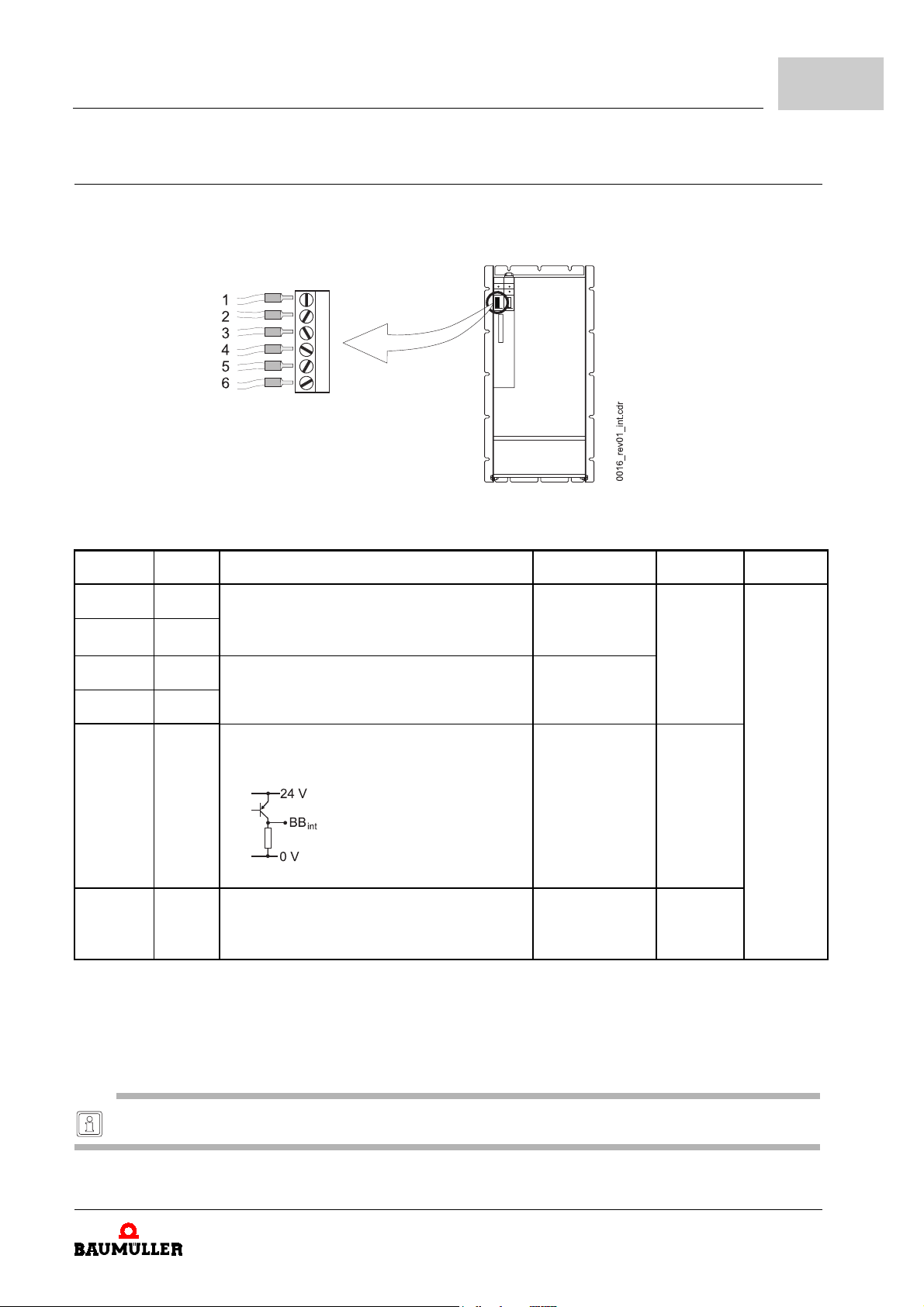
6.5.2.1 Control terminal X99A
Use the supplied screw type connectors to connect terminal X99A. If you need more
screw type connectors please contact Baumüller Nürnberg Electronic GmbH & Co. KG or
the manufacturer of the connectors directly (see
figure 11: Control terminal X99A
Installation
ZB.1 Connectors– on page 87
6
).
terminal pos.
1)
+24 V 1 + 24 V (PELV)
description
3)
terminal 1 and 2 are bridged internally
+24 V 2
M 24 V 3 ground 24 V (PELV)
terminal 3 and 4 are bridged internally
M 24 V 4
BB
int.
5 message "ready-for-use internal" 4) (PELV)
0 V: supply unit is not ready-for-use
24 V: supply unit is ready-for-use
figure 12: ready-for-use internal
ZUS.
6
reserved (PELV)
If there is no ballast unit connected, connect this contact with contact 1 or 2.
1)
Position, see
*: Voltages that may appear at the terminals
**: Currents that may flow across the terminals
2)
Conductor cross-section. Observe EMC-information when you connect the cables
(see
ZEMC requirements on cable routing (EMC information)– from page 52
3)
Zfigure 10– on page 45
NOTE
The power supply input circuit is fitted with condensers (250µF). When the 24V-supply voltage is switched, charging currents
can occur.
.
).
U
interval
* I
21.6 V (UDC)
to
28.8 V (U
DC
0 V (UDC)
0 V (UDC)
or
24 V (UDC)
(SPS-level)
- -
)
interval
0 A (I
to
10 A (I
0 A (I
to
0,2 A (I
** A
)
eff
)
2.5 mm
eff
)
eff
)
eff
2)
0.2
to
AWG
24
to
12
2
4)
This message is only related to BUM64S/A/F! (see also
Z"ready-for-use feed module"– on page 67
Manual Single Power Unit BUM64S/A/F
Document no.: 5.01056.03
).
47
of 118
Page 48
6.5
6.5.2.2 Control terminal X99AB
Connections
Use the supplied screw type connectors to connect terminal X99A. If you need more
screw type connectors please contact Baumüller Nürnberg Electronic GmbH & Co. KG or
the manufacturer of the connectors directly (see
.
WARNING
The following
m
serious personal injury m death
The hazard is: Electricity.
Take care to use multiple separate supply if you demand higher currents.
may occur,
ZB.1 Connectors– on page 87
if you do not observe this warning information:
).
48
of 118
Manual Single Power Unit BUM64S/A/F
Document no.: 5.01056.03 Baumüller Nürnberg Electronic GmbH & Co. KG
Page 49
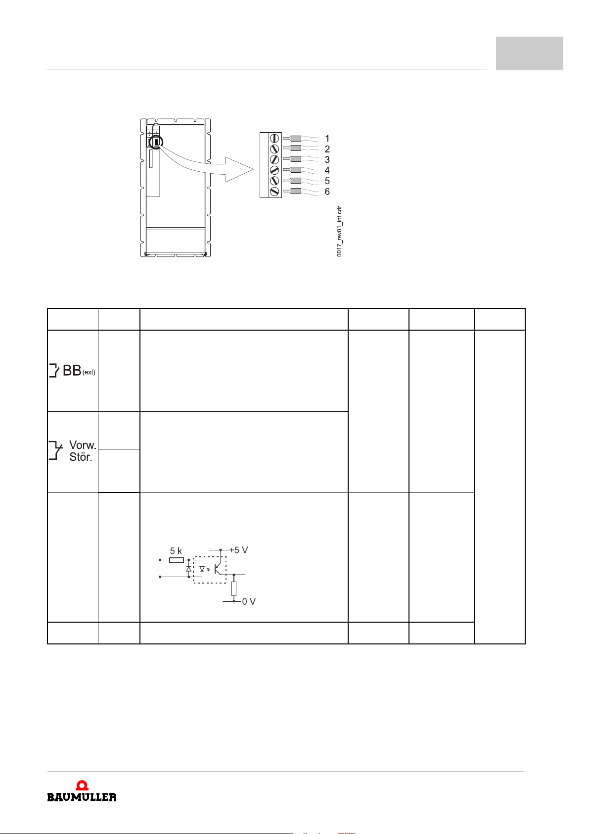
figure 13: Control terminal X99A
Installation
6
terminal pos.
1 Message
1)
description
"ready-for-use external"
Open contact:
supply unit not ready-for-use
2
Closed contact:
supply unit not ready-for-use
3 Message
Closed contact:
"Warning"
(PELV)
supply unit - no warning
4
Open contact:
supply unit - warning
+Reset 5 potential free optocoupler input for
reset of error messages (PELV)
PHASE ERR, POWER ERR, and BRAKE
OVERL.
(PELV)
U
interval
* I
0 V (UDC)
to
24 V (UDC)
0 V (UDC)
or
24 V (UDC)
** A
interval
0 A (IDC)
to
0.5 A (IDC)
10 mA (IDC)
to
25 mA (IDC)
2)
max.
2.5 mm
2
figure 14: potential free optocoupler input
M Reset 6 Reference potential for +Reset input (PELV) 0 V -
1)
Position, see
*: Voltages that may appear at the terminals
**: Currents that may flow across the terminals
2)
Conductor cross-section.
Zfigure 12– on page 47
.
Manual Single Power Unit BUM64S/A/F
Document no.: 5.01056.03
49
of 118
Page 50
6.5
6.5.2.3 Safety relay X68
Connections
With the safety relay the drive can be switched to a torque-free state. This is achieved by
switching off +24 V at contacts 3 and 4.
WARNING
The following
m
serious personal injury m death
The hazard is: mechanical influence because of safety relay failure.
Take care, that contacts 1 and 2 are loaded by a minimum current of 10 mA while in service.
Operate the safety relay within its specifications.
Coil side
rated voltage 24 V (PELV)
operating voltage 19 V to 37 V at Tu = 20 °C (PELV)
may occur,
if you do not observe this warning information:
coil resistance 660 Ω to 905 Ω
Contact side
switching voltage U
switching voltage U
switching current max. 5 A
continuous current min. 10 mA up to max. 6 A
switching capacity P
switching capacity P
AC
DC
AC
DC
max. 25 V
max. 60 V (PELV)
max. 150 VA
max. 30 W
AC
(PELV)
50
of 118
Manual Single Power Unit BUM64S/A/F
Document no.: 5.01056.03 Baumüller Nürnberg Electronic GmbH & Co. KG
Page 51
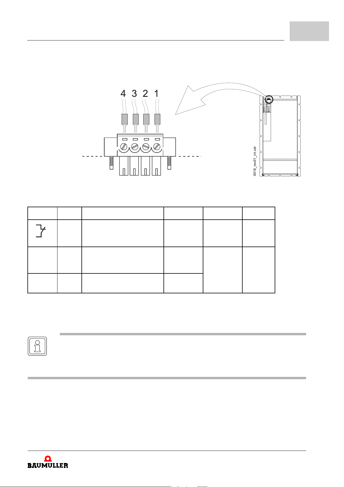
figure 15: Safety relay X68
Installation
6
terminal pos.
1
2
1)
Feedback, if the
safety relay
is enabled (PELV)
description
+24 V 3 + 24 V- connection to disable
the safety relay (PELV)
M 24 V 4 reference point to input
+
24 V (PELV)
1)
Position see
*: Voltages that may appear at the terminals
**: Currents that may flow across the terminals
2)
Connection cross-section of conductor
Zfigure 14– on page 49
.
NOTE
When operating the motor, terminal 3 must be connected to +24 V (UDC) and terminal 4 must
be connected to 0 V (U
DC
).
„Safety relay OFF“ is saved as a message and must be reset by use of the controller.
U
interval
* I
0 V (UDC)
or
24 V (UDC)
0 V (UDC)
to
24 V (UDC)
0 V (UDC)
** A
interval
0.01 A (IDC)
to
5 A (IDC)
0 mA (IDC)
to
35 mA (IDC)
2)
1.5 mm
1.5 mm
2
2
A detailed description of the safety relay is to be found in
from page 107
Manual Single Power Unit BUM64S/A/F
Document no.: 5.01056.03
ZAppendix E - Safety relay–
51
of 118
Page 52

6.6
Fuses of the appliance
6.6 Fuses of the appliance
To protect the appliance or the cable connections to it when an earth leakage fault occurs,
you should install appropriate fuses. Use the fuses listed in ZD.4 Fuses– on page 103
6.7 EMC requirements on cable routing (EMC information)
Modern semiconductor technologies are applied in these appliances which minimize the
power loss in the unit by switching more quickly and, with this, to continually reduce the
size of the power section. These semiconductors generate electromagnetic waves due to
the high switching frequency. As a result, when running converters you must meet spe
cific conditions to avoid electromagnetic influences caused by switching operations.
Disturbances can occur in all sections of the drive system and are caused by:
m
capacitive fault currents caused by high rates of voltage rise when semiconductors
switch.
m
high currents and high rates of current rise in the motor cables. The disturbance energy
bound in magnetic fields reaches frequencies of between a few Hertz and about
30
MHz. Due to the high rates of current rise, additional electromagnetic fields occur
with frequencies of up to approximately 600 MHz.
m
high clock rates and fast logic circuits
(electromagnetic field/16 MHz up to 1 GHz).
m
system perturbation and harmonics. The reason for this are commutation processes
and non-sinusoidal mains network loads especially with network controlled converters
(100 Hz up to 20 kHz).
!
-
NOTE
In this Manual you find the most important information for an EMC-compatible installation.
Further absolutely notes, which have to be complied with, to mount a CE-confom installation
is to be found in the operation manual „filter for mains applications“.
6.7.1 German EMC law (EMVG)
This appliance complies with § 6 sect. 9 of EMVG dated 18.09.1998:
"Devices, systems and components in the sense of section 3, that are exclusively manufactured or stocked as vendor parts or spare parts for further processing by industrial
companies or craftsmen or by other specialists in the field of electromagnetic compatibility
do not need to comply with the protective requirements of § 4 sect. 1 no. 1 to 3 and 5."
EMC largely depends on how the individual components and units are assembled and interconnected within the switching cabinet. The information given on the next pages is intended to enable you to configure your plant according to the newest EMC knowledge.
This way you can keep the respective legal regulations.
6.7.2 Measures to ensure EMC
To ensure EMC you should strictly keep to the following configuring information.
52
of 118
Manual Single Power Unit BUM64S/A/F
Document no.: 5.01056.03 Baumüller Nürnberg Electronic GmbH & Co. KG
Page 53
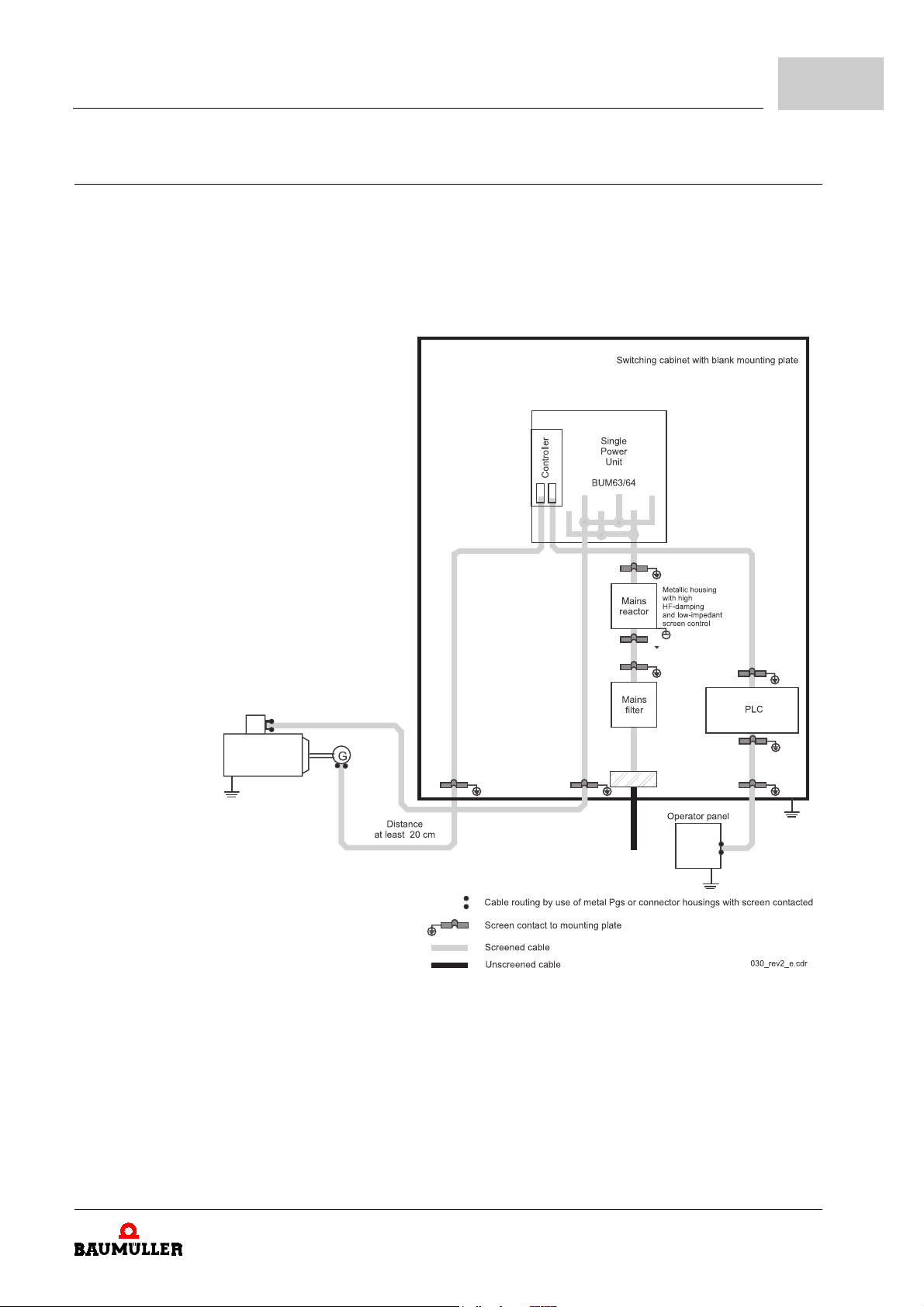
6.7.2.1 Cabling
Installation
h
screen
ZScreening– from page 56
ing cabinet has a sufficiently high screen damping (see limit value for radio disturbance
emission according to EMVG for your plant) and if the EMC compatibility inside the
switching cabinet is guaranteed (this you can assume, when you have observed all
configuration instructions given in this manual).
cables connected, so the cables are kept free from perturbing radiation (see
all
). You can mount unscreened control cables, if the switch-
6
figure 16: Cabling suggestion for BUM64S/A/F
m
If you use Baumüller motor cables you can assume, that the permissible limit values
are not exceeded.
m
The maximum length of the motor cable is limited. The length depends on the crosssection of the cable ZCable from appliance to motor– from page 105
m
The motor cable between converter and motor must consist of one single piece.
Do not interrupt the cable by e.g. terminals, circuit breakers, fuses etc.
Manual Single Power Unit BUM64S/A/F
Document no.: 5.01056.03
.
53
of 118
Page 54
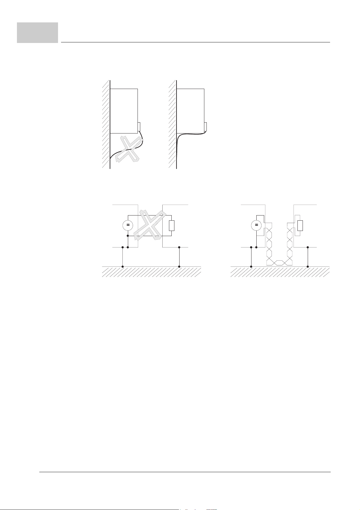
6.7
EMC requirements on cable routing (EMC information)
h
you achieve the lowest possible effective antenna height by routing the cable directly
alongside of a metallic surfaces
figure 17: Reducing effective antenna height
h
you should route all lines as close as possible to the conductors of the ground system
to reduce the effective loop area for magnetic coupling
.
.
figure 18: Reducing loop area
h
when parallel-routing signal and control lines across power cables, the conductors
must at least be 20 cm apart.
h
lines of different EMC categories should only cross at an angle of 90°.
h
for symmetrical signal transmission form twisted pair cables and twist those against all
other twisted pairs (e.g. for differential amplifier inputs used for speed setpoint value).
h
the appliance-to-ground plate earth connection should be as short as possible
(<
30 cm). Use large cross-sections (> 10 mm2).
h
the PE-connection on the load side of the filter to the mounting plate should be carried
out low-impedant. Ideal is a galvanized metal angle piece or a high frequency earth
band.
h
keep a distance of at least 20 cm between converter and its cabling and
m
disturbance sources as circuit breakers, transformers, line reactors and
m
disturbance sensitive modules like µPs, bus systems etc.
h
avoid reserve loops on overlong cables.
h
the grounding on reserve conductors in cables is mandatory (additional screening is
achieved, you avoid capacitive coupled hazardous contact voltages coupled in).
h
do not arrange net filters in parallel.
54
of 118
Manual Single Power Unit BUM64S/A/F
Document no.: 5.01056.03 Baumüller Nürnberg Electronic GmbH & Co. KG
Page 55
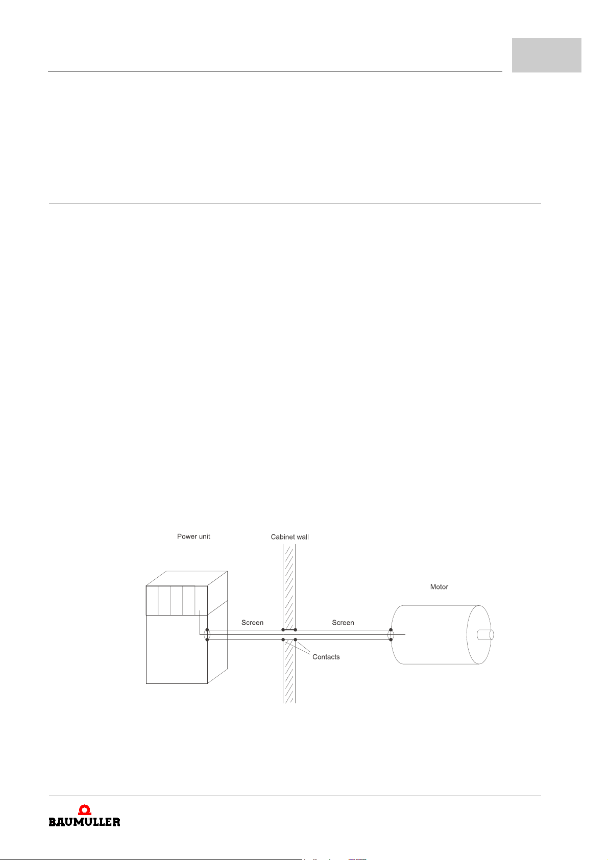
6.7.2.2 Grounding
Installation
h
do not arrange net filters of the same type in series - the damping characteristics are
not improved.
h
for each unit use a separate mains filter. If you must suppress all drives together - do
not interrupt the screening between the converter and the motor. This means that
screened cables must not be interrupted by fuses, circuit breakers and other.
To meet EMC requirements, the classical star grounding is no longer sufficient to reduce
the disturbance of high frequencies caused by converter operation. Better results can be
achieved by a reference surface which must be linked to the unit’s ground (e.g. bare metal
mounting plate and housing parts).
h
to avoid earth loops, position all ground conductors and screens as close as possible
to ground.
h
if it is possible to ground the controller reference potential of unit, form the connection
with as large a cross-section as possible and short (< 30 cm) cable (if it is possible to
ground the controller reference potential).
h
remove insulating layers such as paint, adhesives etc. from the ground connections.
h
if necessary, use serrated lock washers (DIN 6798) or similar measures to ensure a
permanent, conductive contact.
6
h
to prevent corrosion on ground connections, use suitable metal combinations (in the
sense of the electrochemical series of metals).
h
keep conductive electrolytes away from the connection by the use of protective coating
(e.g. with grease).
h
connect screens at both ends over a large contact surface and with good conductivity.
Only this way you can suppress the effects of magnetic or high frequency disturbance.
h
if earth loops occur (e.g. double insulation of the setpoint conductor screen), apply the
receiver side galvanically and the sender side capacitively.
h
when routing external cable screens through panels separating different EMC areas,
ensure contact of the panels to the cable screens.
figure 19: contacting cable screens when routing through cabinet panels
Cables which are passed through the panels of screening housings without special measures (e.g. filtering), may impair the screening effect of these housings.
Manual Single Power Unit BUM64S/A/F
Document no.: 5.01056.03
55
of 118
Page 56
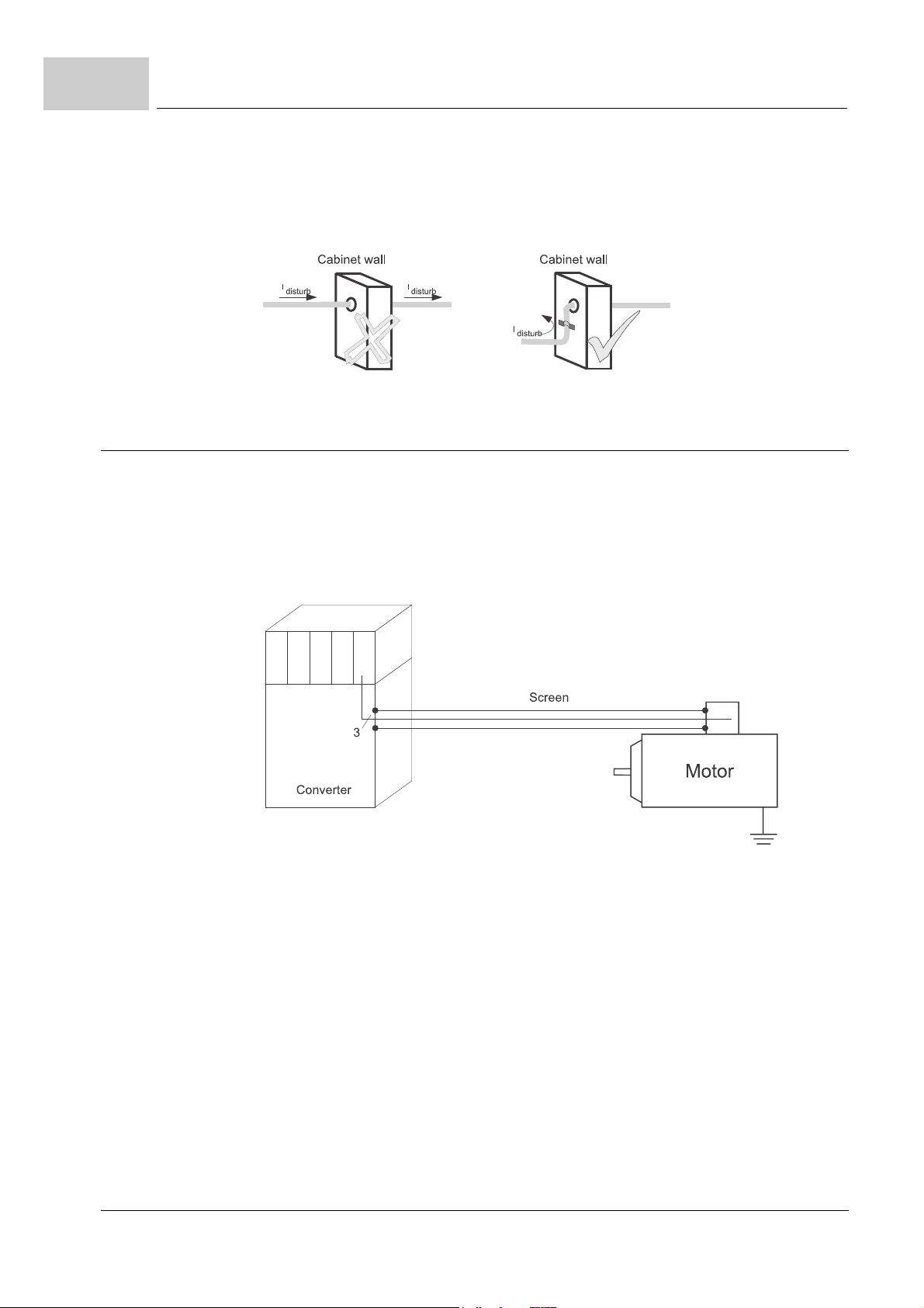
6.7
6.7.2.3 Screening
EMC requirements on cable routing (EMC information)
h
form a good conductive connection of the cable screens where the cable enters the
housing.
h
take care that the distance of the last screen contact point to the exit of the cabinet
must be as short as possible.
figure 20: Screening of cables at switching cabinet exit
The screening is effective against magnetic fields if the screen is connected to ground on
both ends.
With electrical fields, the screen is effective when it is connected to ground at only one
end.
h
however, in case of (both electrical or magnetic) fields with high frequencies (depending on the length of the line), you must always connect the screen at both ends.
figure 21: Screen contact on both sides of a line
Connecting the screen to ground at both ends ensures that the conductor does not “leave
the system housing“.
Grounding of conductor screens on both sides does not entirely rule out the influence of
earth circuits (potential differences on the ground system). Those are very rare, if you car
ry out the measures described in the previous sections entitled (
ZGrounding– from page 55
and (
You can also form a capacitive RF connection of a screen to ground. This prevents low-
frequency interference due to earth circuits.
).
ZCabling– from page 53
)
56
of 118
h
screened cables that are routed through different EMC areas must not be interrupted
at terminals, since screen damping would otherwise be reduced considerably.
h
if possible, run the cables without interruption to the next module.
h
carry out the screen connection low-impedant and use a wide surface.
Manual Single Power Unit BUM64S/A/F
Document no.: 5.01056.03 Baumüller Nürnberg Electronic GmbH & Co. KG
Page 57
NOTE
The screen braiding must have a coverage of at least 85%.
The following cables have a particularly high interference potential:
m
m
m
6.7.2.4 Filtering
Installation
Cable tails that are only 3 cm long (1 cm of wire = 10 nH) reduce the screening effect in
the megahertz range by up to 30 dB!
motor cable
cable to external ballast resistors
cable between mains filter and converter
The functioning of the unit requires no filters to be fitted. To keep EN50081-2 respectively
EN61000-6-4 under certain circumstances input or output side filters may be required.
If you have question on how to perform filtering you can order manual “Filter for network
applications BFN“.
6
6.7.2.5 Filter mounting
h
arrange the filter close to the appliance.
h
use a screened mains input line between unit and filter if the cable length exceeds
30 cm (grounding on both sides).
h
input and output cables of the filter should be run separate of each other (distance >
30 cm).
h
the housing of the filter should be grounded using a wide surface.
6.7.2.6 Discharge currents
Due to the principle of operation, parasitic capacities in the power unit, motor cable and
motor windings can add to discharge currents of 100 mA or higher.
This means that converters may be incompatible with earth leakage circuit-breakers!
h
in this context observe the safety information given in the EN 50178/VDE 0160 sect.
5.2.11.2. standard.
Manual Single Power Unit BUM64S/A/F
Document no.: 5.01056.03
57
of 118
Page 58
6.8
Connection diagram
6.8 Connection diagram
h
run the cables according to EMC rules and connect them as shown in the connection
.
WARNING
The following
m
The hazard is: Electricity.
Take care that the permissible connected load (see
101) is never exceeded!
Reinstall the coverages that came with the appliance and tighten the screws of the coverages
after you have finished the power cable connection.
Make sure, that the total power requirement of the motors fed by the power modules connect-
ed to the BUM64S/A/F is not higher as the power, the infeed power converter within the
BUM64S/A/F can supply.
diagram.
may occur,
serious personal injury m death
if you do not observe this warning information:
ZElectrical specifications– from page
58
of 118
Manual Single Power Unit BUM64S/A/F
Document no.: 5.01056.03 Baumüller Nürnberg Electronic GmbH & Co. KG
Page 59
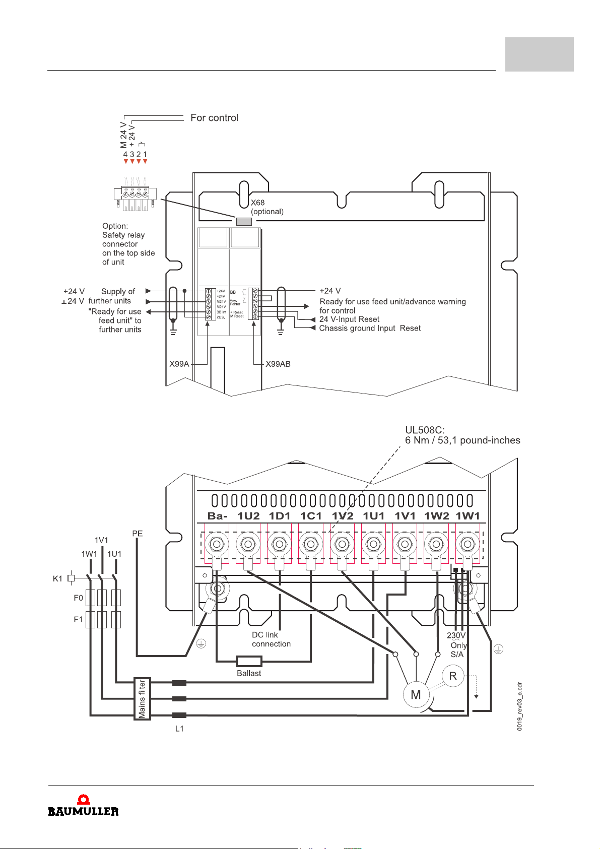
Installation
.
6
figure 22: BUM64S/A/F connection diagram
Manual Single Power Unit BUM64S/A/F
Document no.: 5.01056.03
59
of 118
Page 60
6.9
Fastening according to UL
Information about the respective connections you will find in section
from page 45.
Below we have listed more connection information.
F0 Line protection fuse,
fuse depends on the cable used
(DIN VDE0100-430)
F1 Semiconductor fuse or extreme range fuse (see
page 103)
K1 Line contactor
(auxiliary contact for control unit release optional, not obligatory)
Mains Filter Mains filter (see
L1 Line reactor(see
+ 24 V
24V
24 V power supply with secure separation (PELV) acc. to IEC
61131-2; table7 to supply the electronics section.
6.9 Fastening according to UL
ZB.5 EMC accessories– on page 90
ZB.4 Line reactors– on page 89
ZPower terminals–
ZD.4 Fuses– on
)
)
Use a torque wrench with, if you carry out fastening according to UL508C.
60
of 118
Manual Single Power Unit BUM64S/A/F
Document no.: 5.01056.03 Baumüller Nürnberg Electronic GmbH & Co. KG
Page 61
The commissioning is divided into the following steps:
check mounting
1
check installation
2
check safety devices
3
check operating and display elements
4
Further information about these steps will be given in the following sections.
7.1 Requirements the executing personnel must meet
7C
OMMISSIONING
7
WARNING
The following
m
serious personal injury m death
The hazard is: Electricity. When this electrical appliance is in operation, certain parts of it
conduct dangerous voltages.
Make sure, that only qualified personal which is familiar with safety information, mounting-,
operation- and maintenance procedures is working at this appliance.
Qualified personnel are persons who have been authorized by the plant manager to carry
out the activities required, who are able to recognize possible dangers and to avoid them.
They must have the skills, experience, instruction and knowledge of the operational con
ditions and the respective standards, regulations and rules to detect and avoid accidents.
Examples of the qualifications to work with this appliance are:
m
m
may occur,
education, training or authorization to commission, ground and mark appliances according to safety technology standards.
education or training in maintenance and use according of adequate safety equipment
to safety technology standards.
if you do not observe this warning information:
-
Manual Single Power Unit BUM64S/A/F
Document no.: 5.01056.03
61
of 118
Page 62
7.2
Checking the mounting
7.2 Checking the mounting
h
make sure, that the appliance is properly screwed to the switching cabinet.
h
make sure, that the sealing has not been damaged
(for window variants only).
h
make sure, that the coolant circulation is tight (for variants F only).
7.3 Checking the installation
WARNING
The following
m
serious personal injury m death
The hazard is: Electricity. Voltage conducting parts must be protected against direct touch.
This you can achieve by insulation, model, position, arrangement or firmly applied devices.
The power terminals of the power module hold potential!
Essential for personal security are the safety measures and safety regulations of the DIN/VDE
standards. If protective conductor connections are missing at the appliance or at the motor
you will have to face personal damage, because the surfaces may carry dangerous voltages.
The protective conductor connection is to be carried out according to DIN EN 60204/VDE
0113 part 1; section 8.2.2 regarding also EN 50178/VDE 0160, sections 5.3.2.1 and 8.3.4.4.
Under operation there always appear discharge currents in the power module and the motor.
They are conducted by using the orderly protective conductor and can lead to premature re
sponse of a series fault current circuit breaker.
In case of a body contact or a earth fault a direct current component can appear within the
fault current, which can complicate or keep a supervising fault current circuit breaker from re
sponding.
Even after the action of the supply units main contactor the parts of the power module are
carrying dangerous voltages.
h
h
may occur,
check, if the cables leading to the power terminals are routed and connected properly.
check, if the cables leading to the signal (control-) terminals are routed and connected
properly.
if you do not observe this warning information:
-
-
62
of 118
Manual Single Power Unit BUM64S/A/F
Document no.: 5.01056.03 Baumüller Nürnberg Electronic GmbH & Co. KG
Page 63
7.4 Checking the safety devices
WARNING
The following
m
serious personal injury m death
This appliance is conducting dangerous voltages and holds dangerous rotating machines
(ventilators).
Switching cabinets must be equipped with emergency stop devices who are able to cut off all
voltages which can lead to hazards. Not included are appliances that would generate new
hazards after being cut off. The release for the emergency stop device must be placed in a
way that it is fast to reach in case of an emergency. If you carry out operations that hold higher
hazard levels the presence of an additional person is required.
h
h
may occur,
before activating the drive check thoroughly the function of all supervisory safety devices in order to avoid personal hazard.
before commissioning make sure, that all covers for the voltage conducting parts (power terminals) are in place and the ventilators have been covered with gratings.
if you do not observe this warning information:
Commissioning
7
h
make sure, that the touch protection has been carried out according §4 section 4 VBG
4 (German regulation).
7.5 Commissioning sequence
WARNING
The following
m
serious personal injury m death
During the first commissioning there is no guarantee that the driven machine elements are
not activated by fault or mistake. Therefore be extra careful during the first commissioning.
Extra care is to be taken when directly or indirectly touching the shaft. This is allowed only
when the shaft is in stand still position and the power module is cut off from voltage. During
operation free accessible machine parts such as shafts or ventilators must be covered.
When an error occurs the drive will be switched off current; the motor will run down without
breaking. This circumstance must be regarded especially in transmission or hauling applica
tions.
h
h
h
may occur,
make sure there are no persons present in the dangerous area of the machine driven.
make sure the plant can be switched off immediately by emergency stop devices.
switch on the appliance and be aware of faulty or uncontrolled conditions of the plant.
if you do not observe this warning information:
-
Manual Single Power Unit BUM64S/A/F
Document no.: 5.01056.03
63
of 118
Page 64

7.5
Commissioning sequence
64
of 118
Manual Single Power Unit BUM64S/A/F
Document no.: 5.01056.03 Baumüller Nürnberg Electronic GmbH & Co. KG
Page 65
The application is operated by use of the controller unit only (see controller manual). The
only exception from this is the reset (acknowledgment) of errors by use of the optocoupler
input "Reset" within X99AB plug-in connector.
In this chapter we do not describe the principles of operation itself, but the monitoring
functions and display elements that the appliance has.
8.1 Safety regulations
WARNING
The following
m
serious personal injury m death
may occur,
8O
if you do not observe this warning information:
8
PERATION
Report immediately any situation that might lead to a deterioration of security.
Before demounting safety devices for purposes such as commissioning or repair jobs, set the
machine or plant out of service strictly according to the regulations.
Re-mount the safety devices again, and make sure they are put into operation immediately
after commissioning or repairs are completed.
8.2 Monitoring functions and their messages
NOTE
The monitoring functions are active only when the +24V-supply voltage (X99A) is present.
The unit’s monitoring functions are divided into two groups. First group is the "infeed module monitoring functions" see
power module monitoring functions". This partitioning reflects the appliance’s internal
construction.
Zfigure 4– on page 29
. Second group is the "motor-side
Manual Single Power Unit BUM64S/A/F
Document no.: 5.01056.03
65
of 118
Page 66
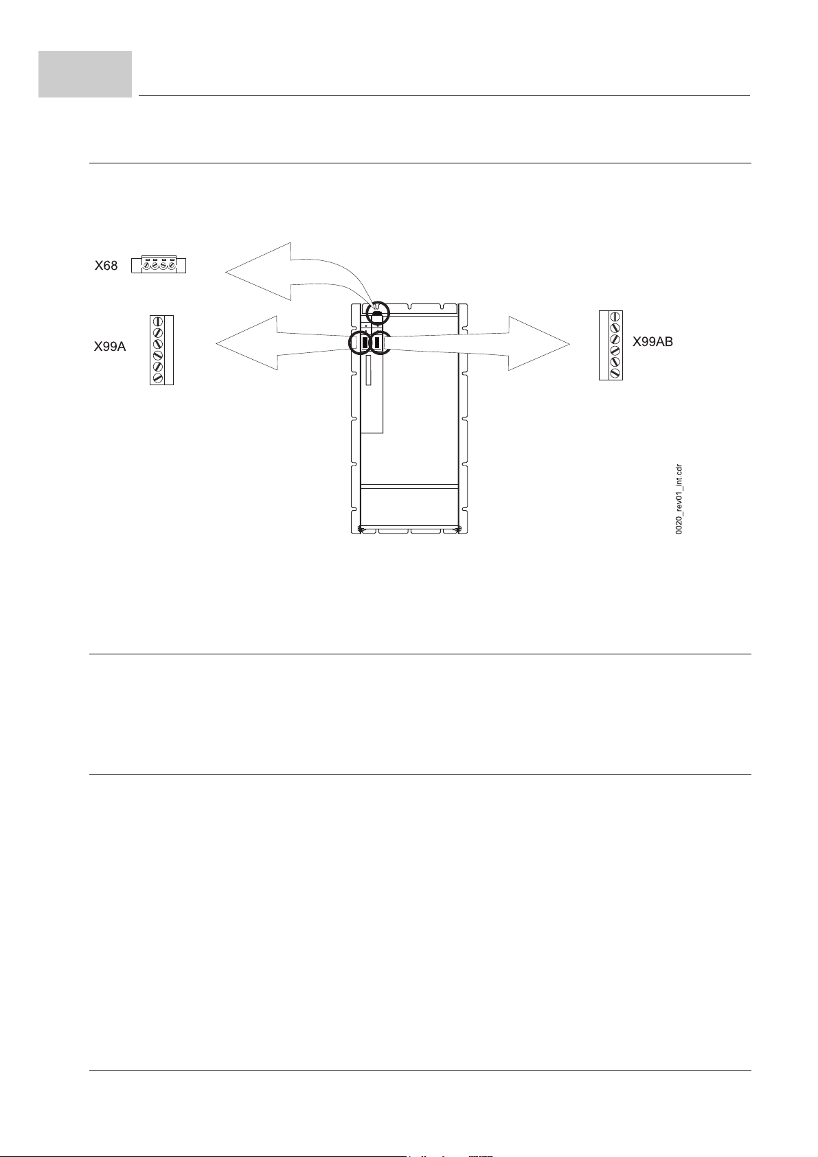
8.3
8.2.1 Monitoring functions of feed module
Ready-for-use (= BB)
The messages generated by the "infeed module monitoring functions" are transmitted
outside by using relay contacts. Simultaneously the messages are transmitted to the con
troller and processed there.
-
figure 23: Position of relay contacts
Further information about messages and their respective relay contacts you will find un-
ZMessages over relay contacts– on page 72
der
8.2.2 Monitoring functions of motor-side power module
The messages generated by the "motor-side power module monitoring functions" are exclusively transmitted to the controller and processed there. Further information you will
find under ZMonitoring functions– from page 69
8.3 Ready-for-use (= BB)
The “ready-for-use“ message is the most important message. When a monitoring function
generates a message, that erases the "ready-for-use" message, the drive will be stopped.
There is not only one single message “ready-for-use“. If, for example there is a V-controller in your BUM 64S/A/F, each drive will have four different "ready-for-use" messages.
m
"ready-for-use feed module" (in BUM 64S/A/F existent and visible)
= "ready-for-use internal" (digital output X99A - 5)
= "ready-for-use external" (relay contacts X99AB - 1,2)
m
"ready-for-use power module" (in BUM 64S/A/F existent and
m
"ready-for-use controller" (existent in controller)
m
"ready-for-use group" (existent in controller)
.
.
visible)
not
66
of 118
The "ready-for-use group" message depends on three other ready-for-use messages.
Only if the messages "ready-for-use feed module" and "ready-for-use power module" and
Manual Single Power Unit BUM64S/A/F
Document no.: 5.01056.03 Baumüller Nürnberg Electronic GmbH & Co. KG
Page 67
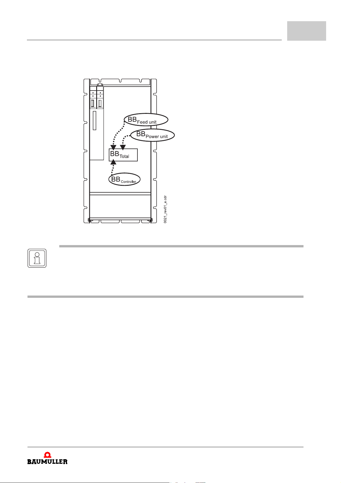
Operation
"ready-for-use controller" are present, the message "ready-for-use group" will be generated (see
Zfigure 24– on page 67
).
8
"ready-for-use
feed module"
figure 24: „ready-for-use“
NOTE
After applying +24V-supply and mains input voltage it will take approximately 5 s for the appliance to be ready-for-service.
"ready-for-use power module" after approx. 0.5 s, „ready-for-use feed module" after approx.
2 s, "ready-for-use controller" after approx. 4.5 s
In the following sections we will give information about the different "ready-for-use" messages.
When the "infeed module monitoring functions" do not detect any errors, the monitoring
function generates the "ready-for-use feed module" message.
m
if "
ready-for-use feed module
F switches the drive to a torque-free state, the power module will produce no more
power.
The BUM 64S/A/F displays this message by use of a LED. At the same time the message
is transmitted to the relay contacts. Information about this you will find under ZMonitoring
functions– on page 69 and
The term "ready-for-use feed module" is also called "ready-for-use internal" (terminal designation BB int) respectively "ready-for-use external" (terminal designation BB ext).
The distinction has its reason only in the construction of the unit.
At the infeed module output the "ready-for-use feed module" is also called "ready-for-use
internal". After the message has been transmitted inside the unit to the power module,
the "ready-for-use feed module" message is also referred to as "ready-for-use external".
" is erased by the monitoring function, the BUM 64S/A/
ZMessages over relay contacts– on page 72
.
Manual Single Power Unit BUM64S/A/F
Document no.: 5.01056.03
67
of 118
Page 68

8.3
Ready-for-use (= BB)
"ready-for-use
motor-side power
module"
"ready-for-use
controller"
"ready-for-use
group"
If the "monitoring function motor-side power module" detects no errors, the monitoring
function generates the "ready-for-use motor-side power module" message.
If the message "ready-for-use motor-side power module" is erased by the monitoring
function, the BUM 64S/A/F switches the drive to a torque-free state, the power module
will produce no more power.
At the beginning of this section we have mentioned the V-controller. In the documentation
of the controller you are using you will find information about if a "ready-for-use controller"
message is supplied by your controller and if yes, how you can process the "ready-foruse controller" message.
Here also applies the above mentioned. In the documentation of the controller you are
using you will find information about if a "ready-for-use controller" message is supplied by
your controller and if yes, how you can process the "ready-for-use controller" message.
68
of 118
Manual Single Power Unit BUM64S/A/F
Document no.: 5.01056.03 Baumüller Nürnberg Electronic GmbH & Co. KG
Page 69
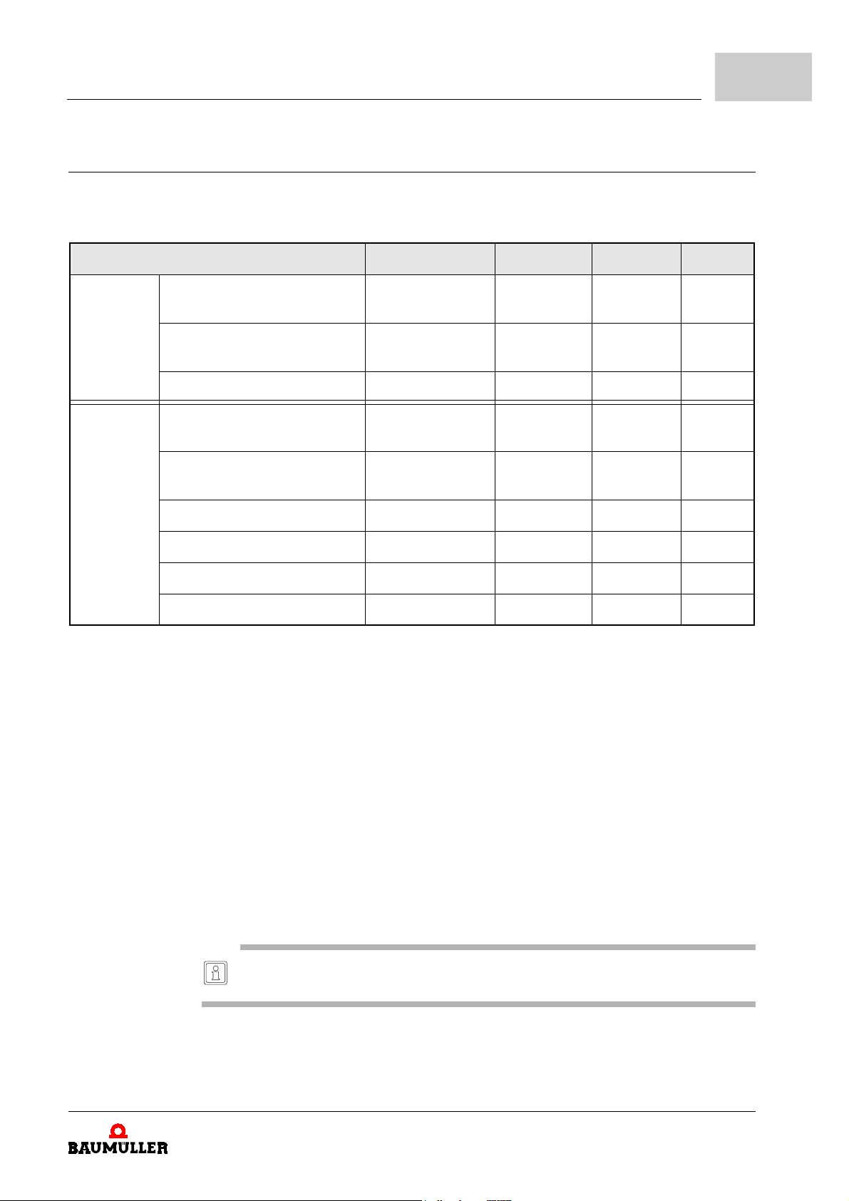
Operation
8.4 Monitoring functions
The following table lists all monitoring functions of the power unit. A description of each
monitoring function you will find on the following pages
monitoring function LED relay V-controller reset
8
feed
module
motor-side
power
module
phase failure WARNING
PHASE ERR.
mains network failure WARNING
POWER ERR.
short-circuit ballast output
overcurrent (motor)
e.g. short-circuit
earth current (motor)
e.g. short to earth
DC link overvoltage
BRAKE OVERL. - F 0110
- - F 0202
- - F 0203
- - F 0201
X99AB; 3,4
X99AB; 3,4
heatsink overtemperature - - F 0205
internal auxiliary voltage - - F 0204
safety relay
1)
The V-controller display this accumulative error message when there is an error in the feed module. Which
error has occurred is shown by the respective LED on the unit’s front side.
2)
Trigger the reset input (+24V and M24V applied at X99AB, optocoupler input).
or
cut off +24V-supply voltage.
That way
If you react on the WARNING you will have the possibility, to bring the drive into a defined operational status,
before the power module erases the "ready-for-use feed module" message and switches to powerless state.
3)
Not possible by use of the reset input! For safety reasons you must wait, until the DC link is discharged (U
< 20 V). After that you can switch off the +24V-power supply.
That way
4)
The message must be erased by a reset of the controller.
Display and erasure of the message is described in the controllers documentation
5)
A message only appears, when the safety relay is switched off. The safety relay is switched off, when the
+24V-supply voltage is not present at the relay.
Before you are enabled to erase the message by a reset of the controller, you must restore the +24V-supply
voltage at the relay.
messages of the feed unit will be erased!
all
messages of the feed unit will be erased!
all
- X 68; 1,2
5)
F 0110
F 0110
F 0206
1)
1)
1)
24 V
24 V
U
ZK
contr.
contr.
contr.
contr.
contr.
contr.
3)
DC
DC
2)
2)
4)
4)
4)
4)
4)
4) 5)
ZK
NOTE
: If the message cannot be reset, it is very likely, that the reason for the error is still there.
Reset
Manual Single Power Unit BUM64S/A/F
Document no.: 5.01056.03
69
of 118
Page 70
8.4
8.4.1 Monitoring functions of feed module
Monitoring functions
m
Monitoring function phase failure
The voltage of all three phases of the mains input is monitored. If one of the phases has
no voltage, the BUM 64S/A/F generates a WARNING. When the voltage returns within
10 seconds, the WARNING message is erased. If the voltage at the mains phase is miss
ing for longer than 10 seconds, the message WARNING remains and the "ready-for-use
feed unit" will be erased.
m
Monitoring function mains network failure
The voltage of all three phases of the mains input is monitored. If the mains voltage is
missing at 2 or 3 phases, immediately the message “WARNING“ is generated. When the
mains input voltage returns as long as the DC link voltage is above 300
charged again and the WARNING message is erased.
If the DC link voltage drops below 300 V after mains network failure or mains voltage dips,
the „ready-for-use feed module“ is erased. When the mains input voltage returns the wir
ing of the X99AB-5/6 input determines the further behavior:
m
if you apply shortly (> 1 ms) 24 V, the DC link is re-charged, the WARNING message will be erased, and the "ready-for-use" is set again.
m
if the input is permanently connected to 24 V, the DC link is automatically re-charged
after the mains input voltage returns. The WARNING message will be erased, and
the "ready-for-use" is set again.
(Prerequisite is, that a mains network failure time > 0 seconds is set. See "mains
network failure time" in the controller manual).
.
-
V, the DC link is
-
WARNING
The following
m
serious personal injury m death
The hazard is: mechanical influence.
Carry out protective measures on the machine side, if you want to enable an automatic startup of the drive. The automatic start-up holds tremendous dangers for the operational person
nel.
may occur,
if you do not observe this warning information:
-
70
of 118
Manual Single Power Unit BUM64S/A/F
Document no.: 5.01056.03 Baumüller Nürnberg Electronic GmbH & Co. KG
Page 71
8.4.2 Monitoring functions of motor-side power module
m
Monitoring function overcurrent (motor)
Any of the three phase currents of the motor is monitored.
If the phase current exceeds the admissible peak value current by 30 %, the pulse inhibitor is activated and the BUM 64S/A/F generates a message. This message is saved within the BUM 64S/A/F and transmitted to the controller. The "ready-for-use motor-side
power module" message is erased.
NOTE
The overcurrent message and the subsequent blocking of the drive protects it from being
damaged or destroyed. To avoid the “overcurrent (motor)“ message, you must limit the per
missible peak current of the motor phase currents by the control process.
m
Monitoring function earth current (short-circuit)
The earth leakage current of the motor phases is monitored.
When the fault current exceeds 20 % of the peak value of the power section’s admissible
peak current, a message is generated. The reason for that error is most likely an earth
leakage fault at the motor terminals. This message is transmitted to the controller. The
"ready-for-use motor-side power module" is erased.
m
Monitoring function DC link overvoltage
Operation
8
-
The peak value of the DC link voltage is monitored.
When the DC link voltage reaches 830 V, a message is generated. This message is
passed on to the controller. The message "ready-for-use motor-side power module" is
erased.
NOTE
The DC link voltage can rise until cut-off, when the drive is in breaking operation and there is
no or a too high-resistance ballast resistor at the DC link.
m
Monitoring function heatsink overtemperature
The peak value of the DC link voltage is monitored.
A linear temperature sensor is mounted onto the heatsink. Its measured value is transmitted to the controller. The controller that way is taking over the temperature monitoring
(see controller manual). This must be adjusted according to the technical specifications
given in the controller manual. The "ready-for-use motor-side power module" is erased.
CAUTION
The following
m
property damage.
The hazard is: unit temperature too high. The maximum admissible temperature of the
heatsink is 90 °C - higher temperatures can destroy the appliance.
Adjust the controller in a way, that the "ready-for-use motor-side power module" is erased by
the controller when the temperature of the heatsink exceeds 85 - 90 °C.
may occur,
if you do not observe this caution information:
Manual Single Power Unit BUM64S/A/F
Document no.: 5.01056.03
71
of 118
Page 72
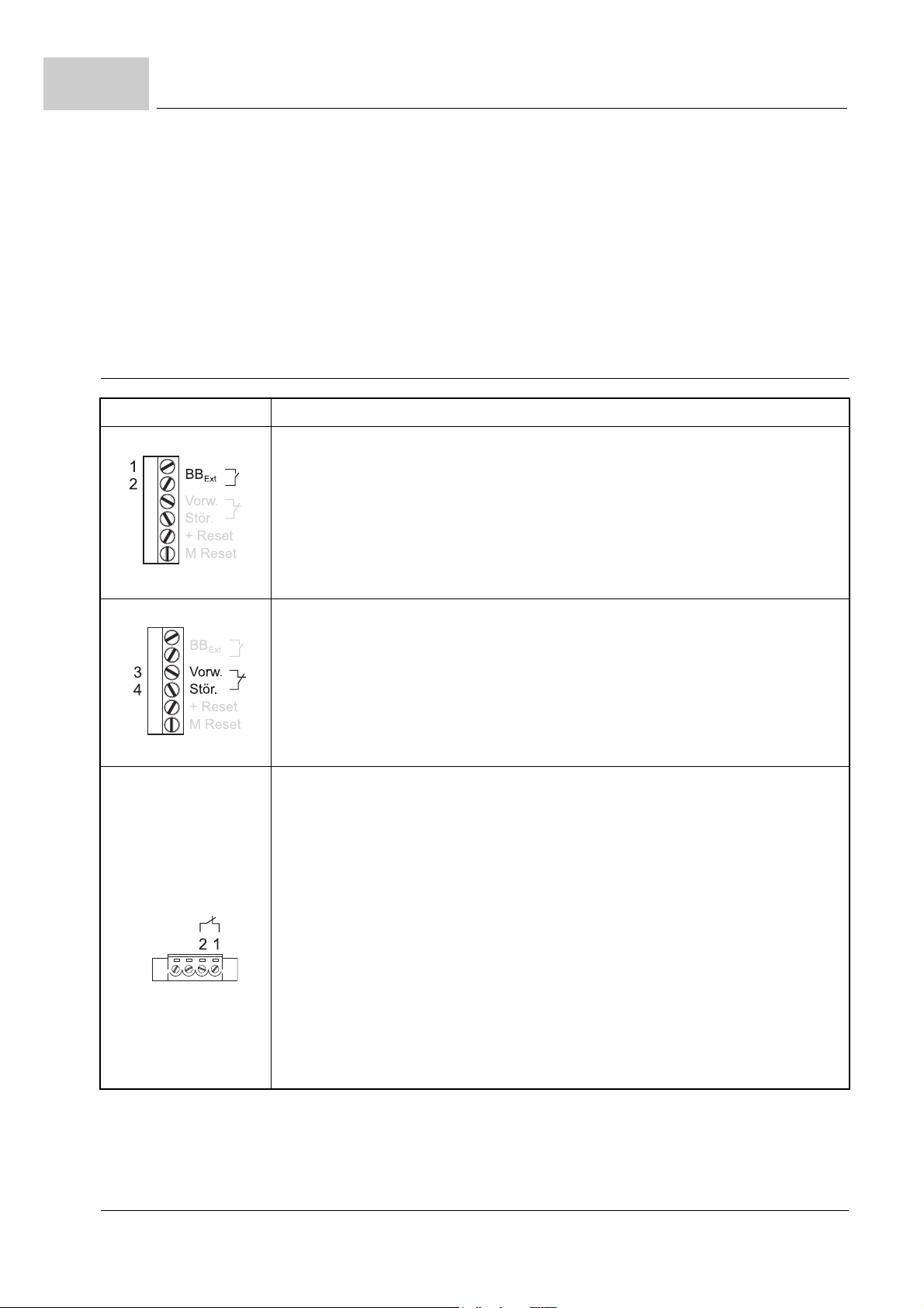
8.4
Monitoring functions
m
Monitoring function internal auxiliary voltage
The voltage required for the driver circuit of the power transistors is monitored.
When the internal auxiliary voltage is missing, a message is generated. This message is
passed on to the controller. The "ready-for-use motor-side power module" is erased.
m
safety relay
(optional)
The switch state of the safety relay is monitored.
Further information about the safety relay you will find in
on page 72 and in
ZAppendix E - Safety relay– from page 107
8.4.3 Messages over relay contacts
clamp terminal description
figure 25: BB_Ext, X99AB
.
figure 26: Prew./error, X99AB
"ready-for-use feed module"
Contact
Message "ready-for-use feed module" not present.
Contact
Message "ready-for-use feed module" present.
further information about "ready-for-use feed module" message you will find in
module"– on page 67.
Pre-warning - error (Pre-warning is a synonym for the better word WARNING)
(Vorw./Stör. = Prew./error)
Contact
Message WARNING not present.
Contact
Message WARNING present.
In which cases this message is generated read under
70.
open
closed
closed
open
:
:
:
:
ZMessages over relay contacts–
.
Z"ready-for-use feed
ZMonitoring functions of feed module– on page
figure 27: X68
With the safety relay you can switch off the supply voltage of the transistor drivers. After cut-off the motor
is torque-free, but is not galvanic isolated from the power module. Because the motor is not galvanic iso
lated from the module, the motor is not voltage-free!
A typical application for the safety relay is:
very fast resumption of operation after cut-off.
f
This is possible, because the DC link is not switched off.
Check back signal of safety relay (safety relay is available as an option)
Contact
no +24V-supply for safety relay. The power output respectively the converter is blocked.
Contact
+24V-supply for the safety relay present. The power output respectively the converter can be driven by
the controller.
If the +24V-supply for the safety relay is cut off while the drive is under operation, the drive is immediately
switched torque-free (the appliance will generate no more energy).
To re-start the drive, keep to the following procedure:
switch on +24V-supply for safety relay.
erase existing messages by a reset of the controller.
closed
open
:
:
-
72
of 118
Manual Single Power Unit BUM64S/A/F
Document no.: 5.01056.03 Baumüller Nürnberg Electronic GmbH & Co. KG
Page 73

Control is the basis of maintenance. If you carry out the inspection carefully, arising problems can be avoided.
9.1 Inspection interval
When the surrounding air is polluted, the required coolant air quantity cannot be
achieved, because the dirt will clog up the ventilation grids.
Even before clusters of dirt inside the appliance can block the required heat dissipation.
Layers of dirt on the ventilation grids are a warning signal which you should keep an eye
on.
h
check the devices (e.g. air filters) within the switching cabinet which ensure the required environmental conditions and be sure to keep the maintenance intervals given
by the manufacturers.
9M
AINTENANCE
9
h
weekly check the specified environmental conditions.
The specified environmental conditions you will find in chapter
specifications– from page 97.
h
monthly check the mixture ratio of the anticorrosive
(applies to window variant F only).
ZAppendix D - Technical
Manual Single Power Unit BUM64S/A/F
Document no.: 5.01056.03
73
of 118
Page 74

9.1
Inspection interval
74
of 118
Manual Single Power Unit BUM64S/A/F
Document no.: 5.01056.03 Baumüller Nürnberg Electronic GmbH & Co. KG
Page 75
10
10R
DANGER
The following
m
serious personal injury m death
Only Baumüller-personnel, that is familiar with safety notes and mounting-, operation- and
maintenance instructions is allowed to repair this appliance.
This appliance conducts dangerous voltages - all repair jobs are to be done only when the
appliance is in powerless state.
Begin to work at the DC link of the appliance only after it has been secured, that neither potential nor voltage (residual charge) is present.
Before demounting safety devices for commissioning or repair jobs, the machine/plant is to
be put out of operation according exactly to the regulations. Right after the commissioning or
repair job is done, all safety devices must be remounted and it must be made sure that they
function correctly.
NOTE
will occur,
if you do not observe this danger information:
EPAIR
The operator of the machine must carry out a complete drive acceptance procedure after every intervention in the drive, no matter if it´s the motor, the actual value encoder or the power
module. Also this has to be written down in a chronological protocol (service note-book etc.)
If this is disregarded, the operator runs the risk of liability consequences.
Manual Single Power Unit BUM64S/A/F
Document no.: 5.01056.03
of 118
75
Page 76

76
of 118
Manual Single Power Unit BUM64S/A/F
Document no.: 5.01056.03 Baumüller Nürnberg Electronic GmbH & Co. KG
Page 77
11
11S
In this chapter, we describe how the BUM64S/A/F is set out of operation and the storage
after.
11.1 Demands on the personnel
The personnel that you order to set the appliance out of operation, must have the required
knowledge and instructions to carry out these jobs properly. The personnel is to be cho
sen in a way that the safety information found on the appliance, its parts and its connections are understood and observed.
11.2 Safety regulations
The sense of the safety regulations during commissioning must be applied to the set-outof-operation procedure as well.
ETTING OUT OF OPERATION
STORAGE
,
-
DANGER
The following
m
serious personal injury m death
The hazard is: Electricity.
Make sure that all electrical connections are switched powerless and are secured against unauthorized reactivation.
The modules inside the appliance (e.g. capacitors) can hold dangerous charges! The capacitors used inside the appliance will take at least 10 min to become discharged by themselves.
Before working at electrical connections check with suitable test instruments that there is no
more voltage at the terminals. Only demount the connecting cable after you are sure that they
are completely powerless.
will occur,
if you do not observe this danger information:
Manual Single Power Unit BUM64S/A/F
Document no.: 5.01056.03
of 118
77
Page 78

11.3
Setting out of operation
11.3 Setting out of operation
The setting out of operation has the following steps:
switch to powerless state and secure against unauthorized reactivation.
1
(approx. 10 min after switching off) test that the connections are voltage free.
2
demount the connections and secure them according to the safety regulations.
3
(if required: demount coolant circulation connections and seal them).
4
make a set-out-of-operation document.
5
11.4 Demounting
Prerequisite for demounting is a completely documented set-out-of-operation procedure.
For the demounting, observe the same regulations and safety information as for „mount-
ing“. Observe in particular that a BUM64A/S/F weighs between 36 kg and 49 kg.
Supply suitable transport devices (hoisting gear, cranes, transportation personnel etc.)
for transport after demounting.
Disengage all mechanical connections to the switching cabinet only after the appliance
has been secured against falling off/falling down.
Keep ready suitable packing material if you intend to store the appliances. If in doubt con-
tact Baumüller Nürnberg Electronic GmbH & Co. During transport observe, that the appliance is not damaged by false supports or severe shocks, see also
Transport– from page 23.
11.5 Storage conditions
The duration of the storage is unlimited if you keep the storage conditions given below:
m
1 K 4 (climatic class)
m
- 30 °C to + 70 °C (temperature range)
11.6 Maintenance during the storage
During storage there is no maintenance necessary.
11.7 Re-commissioning
change the seal.
1
carry out commissioning like for a new appliance.
2
In case you have stored the unit longer than six months, the DC-link capacitors must be
reformed before recommissioning. Therefore you must supply the device for at least 48
hours ready-for-use with supply voltage without giving impulse release.
ZPacking and
78
of 118
Manual Single Power Unit BUM64S/A/F
Document no.: 5.01056.03 Baumüller Nürnberg Electronic GmbH & Co. KG
Page 79
12
In this chapter we describe the correct and secure disposal of BUM64S/A/F-appliances.
During the disposal you will get mainly metal parts (iron- and non-iron metal), electronics
scrap and plastics.
12.1 Safety regulations
The disposal is to be carried out only according to the safety regulations. Observe also
particular local regulations. If you are unable to carry out a proper disposal yourself, con
tact a certified disposal business.
CAUTION
The following
m
environmental pollution.
The hazard is: non-appropriate disposal.
During a fire dangerous materials may be generated or set free.
Do not expose electronic modules to high temperature.
The inner insulation of e.g. various power semiconductors holds beryllium oxide. When
opened, the beryllium dust is dangerous to your health.
may occur,
12D
if you do not observe this danger information:
ISPOSAL
-
Do not open modules.
12.2 Demands on the personnel
The personnel which you instruct to dispose/demount the appliance must have the knowledge and training to carry out these jobs properly. Choose the personnel in a way that it
is secured that safety information on the appliance and its parts are understood and ob
served.
Manual Single Power Unit BUM64S/A/F
Document no.: 5.01056.03
-
79
of 118
Page 80
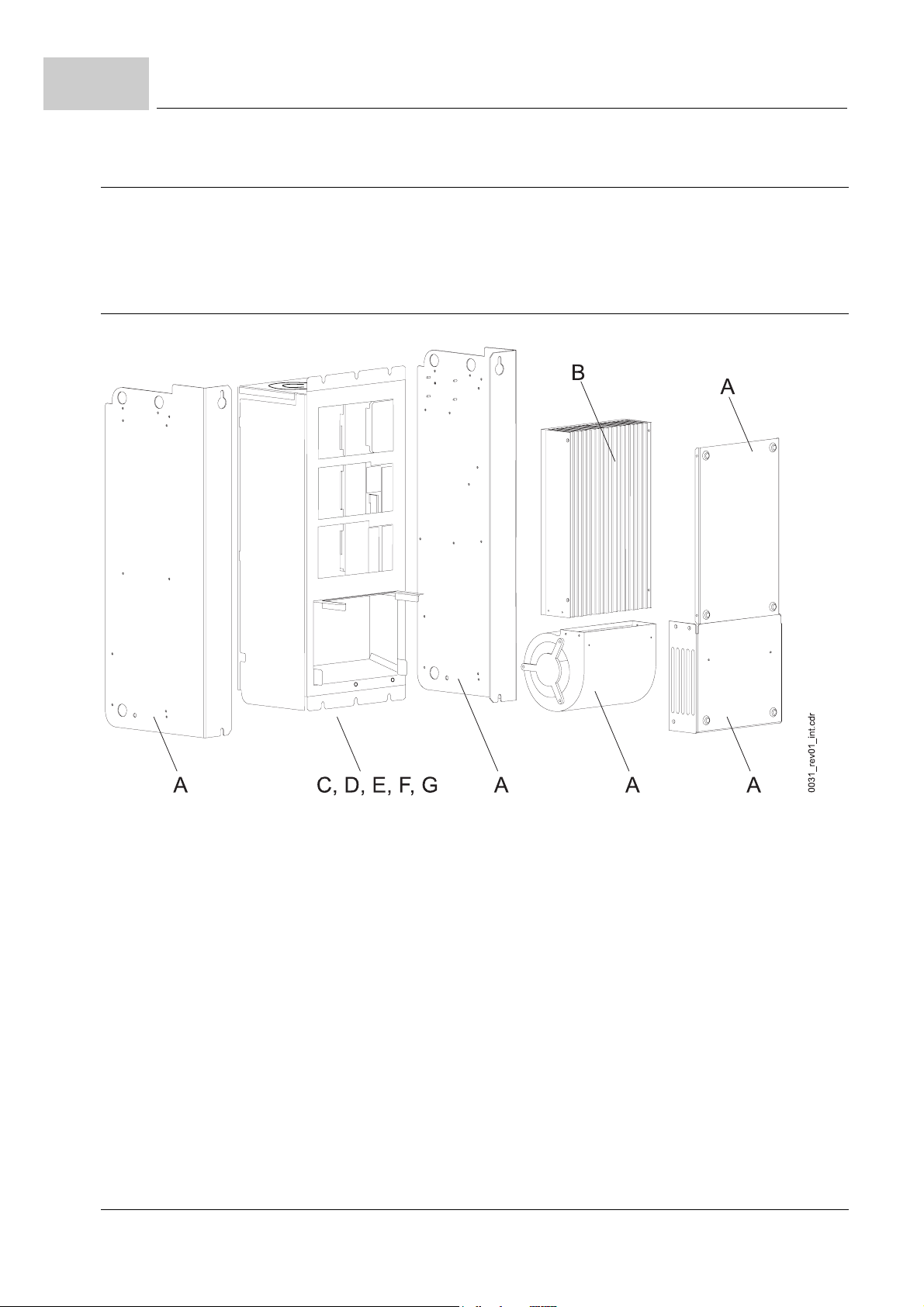
12.3
Disposal instructions
12.3 Disposal instructions
m
Prerequisites
12.3.1 Modules
the appliance has been properly demounted.
m
all technical devices and tools required for demounting are ready-to-use and are in a
good technical condition.
figure 28: Demounting scheme
The modules/units below given in brackets you will find in the figure above.
sheet steel (A)
aluminium (B)
aluminium/copper-compound
plastics (D)
80
of 118
(C)
plastic must be given to the plastics recycling.
Manual Single Power Unit BUM64S/A/F
Document no.: 5.01056.03 Baumüller Nürnberg Electronic GmbH & Co. KG
sheet steel must be given to the iron metal recycling.
aluminium must be given to the non-iron metal recycling.
aluminium/copper-compound must be given to the non-iron metal recycling.
the plastic parts of the housing, the plastic covers and other small parts made from
Page 81
CAUTION
The following
m
environmental pollution.
The hazard is: non-appropriate disposal.
The following elements/modules must be handled as special waste.
may occur,
if you do not observe this danger information:
Disposal
12
condensers (E)
semiconductor
modules
electronic scrap (G)
condensers must be disposed off as special waste. Observe the respective regula
tions.
semiconductor modules must be disposed off as special waste. Observe the respec
(F)
tive regulations.
the electronic scrap from PCBs, which cannot be demounted further, must be recy
cled as special waste. Observe the respective regulations.
12.4 Recycling plants / offices
Make sure, that the disposal is carried out according to your company’s regulations and
the regulations of the disposal companies and official administration. If in doubt, contact
the local business administration, environmental office or other.
-
-
-
Manual Single Power Unit BUM64S/A/F
Document no.: 5.01056.03
81
of 118
Page 82

12.4
Recycling plants / offices
82
of 118
Manual Single Power Unit BUM64S/A/F
Document no.: 5.01056.03 Baumüller Nürnberg Electronic GmbH & Co. KG
Page 83

A
A
Â
AAC
ADC
Aeff
+|IAist|
AO
AC
ADR
AI
AK
AM
ASF
BAPS
BASS
BB
BBext
BBint
BCC
BE
BEDAS
BOF
BS
BSA
BSD
BSE
BUB
A
PPENDIX
Current
Peak current, curve form not defi
ned
Effective value, sinus form current
Effective value, direct current
Current, curve form not defined
Absolute value of armature current
actual value (pos. signal)
Function module Analog Outputs
Alternating current
Adress byte
Function module Analog Inputs
Request-/answer code
f
Asynchronous motor
f
Function module Drive-Manager
Armature contactor enable
Baumüller drives parallel interface
Baumüller drives serial interface
Ready for operation
Readiness for operation (external)
Readiness for operation (internal)
Block check character
f
Component (corresp. to “UU“)
f
Operator’s station
Operating data memory
Begin of file
Function module operating system
Analog reference potential
Digital reference potential
External reference for 24 V con
troller inputs
Ballast unit
A - A
BUC
-
-
BUG
BUM
BUS
CPU
DA
DAC
DB
DC
DE
DES
DIN
DOPPELW
DSV
DW
DWort
EMK
EMC
EN
EOF
ES
Ext
EXT, ext
FBS
FI
FLG
BBREVIATIONS
Baumüller feed-/feedback unit
Baumüller converter basic feed
unit
Baumüller single power unit
Baumüller power module
Central processing unit
Digital/analog
Digital/analog converter
Data byte (8 bit)
f
Direct current
f
Drive-Control
Function module Digital Inputs
Digital input actuator
’Deutsches Institut für Normung
e.V.’,
German institution for standardization
Double word (32 bit)
Function module Data Set Mana
gement
Data word (16 bit)
Double word (32 bit)
Electromagnetic constant
Electromagnetic compatibility
European standard
End of file
Function module Incoming Feeder
Function module Current Monito
ring
External
BEDAS missing
Fault current
Error position encoder signal
-
-
Manual Single Power Unit BUM64S/A/F
Document no.: 5.01056.03
83
of 118
Page 84

A
FPH
FTO
GL
Missing phase
Error tacho signal
Technology module Synchronous
Operation
GRE
HE
HLG
Rectifier end position
Mains contactor ON
Function module Ramp-function
Generator
HM
HS
HSE
HSF
HW
I
I2t
Main menu
Mains contactor
Mains contactor ON
Mains contactor enable
f
High word
f
Hardware
Function module Current Control
Function module Overload Monito
ring
I
Aist
IKG
Armature current actual value
Function module Incremental en
coder
ID-Nr.
I
F
I
Fmax
I
Fmin
I
Fsoll
Inc
IND
Ink
Identification number
field current
Maximum field current (rated cur-
rent)
Minimum field current
Filed current setpoint value
Counting unit of position encoder
Index
Stroke character number of incre
mental encoder
INK.
IPM
I
soll
IW
IWK
IxR
IxR
IZK
KT
Incremental
Intelligent power module
Armature current setpoint value
Actual value
Actual value channel
IxR-compensation with “service“
service
creep speed
IxR-compensation with
“creep speed“
Overcurrent in DC link
Function module Coordinate
Transformation
L
LED
LGE
LT
LW
Function module Position Control
Light-emitting diode
Telegram length
Function module Power Module
Low word
M
M24
MM
$
Mot
Function module Drive-Manager
Reference potential 24 V
f
Function module Motor Model
f
Torque detector
Prefix for hexadecimal number
Function module Field Angle Com
-
puting
MR1
MR2
MT
Torque direction 1
Torque direction 2
Function module Motor Tempera
-
ture
mtr.
n = 0
N
n
ist
-
n
n
max
min
NMX
-
NN
n
SG
n
soll
P
PBE
PELV
PKE
PKW
PNU
-
POS
PWE
PWM
Medium time-lag fuse
Speed = 0
Function module Speed Controller
Speed actual value
Maximum speed
Minimum speed
Maximum speed exceeded
Altitude above sea level
Creep feed speed
Speed setpoint value
Identification number
Parameter description
Protective exta-low voltage
Parameter identifier
Parameter identifier value
Parameter number
Technology module Positioning
Parameter value
Function module Pulse-width Mo
-
dulation
PZD
R
R
A
RA
Res
Process data
Reserved
Armature resistance
Function module Relais Output
Function module Resolver Evalua
-
tion
RF
RS
SE
SELV
Controller enable
Controller blocking
Screen earthing
separated extra low voltage sy
-
stem
SF
SGR
SH
Following error
Current limit reached
Quick stop
84
of 118
Manual Single Power Unit BUM64S/A/F
Document no.: 5.01056.03 Baumüller Nürnberg Electronic GmbH & Co. KG
Page 85

Abbreviations
A
SL
SM
STX
SV
SW
SWG
SWK
TBA
TKK
TM
TMO
U
U
A
UM
USS
UVS
USS
U
ZK
V
V
V
AC
VBG
V
DC
VDE
VE
V
eff
WRE
X
ZK
Protective earth conductor
Synchronous motor
Start of text
Function module Service Interface
f
Setpoint value
f Software
Function module Setpoint Value
Generator
Setpoint value channel
Overtemperature ballast resistor
Overtemperature heat sink
Temperature of motor
Overtemperature of motor
Voltage
Armature voltage
Submenu
Function module USS-protocol
Supply voltage too low
®
Siemens trademark
universal serial interface
DC link voltage, intermediate circuit voltage
Voltage
Peak voltage
Effective value, sinus form voltage
“Verwaltungs-Berufsgenossen
schaft“,
German management occupationcooperative
Effective value, direct current
voltage
“Verband deutscher Elektrotechni
ker“
German electrical engineer connected
Logic element
Voltage, curve form not defined
Inverter limit position
Terminal strip
DC link, intermediate circuit
-
-
Manual Single Power Unit BUM64S/A/F
Document no.: 5.01056.03
85
of 118
Page 86

86
of 118
Manual Single Power Unit BUM64S/A/F
Document no.: 5.01056.03 Baumüller Nürnberg Electronic GmbH & Co. KG
Page 87
B
B.1 Connectors
B.2 Water cooling
A
PPENDIX
Article Article-no. Manufacturer - order no. / type
Male connector for X99A 00309454 Phoenix Contact - MVSTBW 2.5/6-ST
Male connector for X99AB 00303455 Phoenix Contact - MVSTBR 2.5/6-ST
Male connector for X68 00309482 Phoenix Contact - MC 1.5/4-STF-3.81-BD:1-4
Article Article-no.
Sealing tape 00350790
Coupling (connection accessory) BUM64F 00344573
B - A
CCESSORIES
Manual Single Power Unit BUM64S/A/F
Document no.: 5.01056.03
87
of 118
Page 88
B.3
B.3 Fuses
Fuses
For general information about fuses see
B.3.1 Extreme range fuse gR (appliance and cable)
Baumüller 3 350A/660V: 00101951 500A/660V: 00308396
Bussmann 1 350A/690V: 170M4185 400A/690V: 170M4186
2 350A/690V: 170M5884 400A/690V: 170M5885
450A/690V: 170M5886
3 350A/690V: 170M6080 400A/690V: 170M6081
450A/690V: 170M6082
Gould 1 350A/1250V: A1-125E350 D1 400A/1250V: A1-125E400 D1
450A/1250V: A1-125E450 D1 500A/1250V: A1-125E500 D1
550A/1250V: A1-125E550 D1 630A/1250V: A1-125E630 D1
2 350A/1250V: A2-125E350 D1 400A/1250V: A2-125E400 D1
450A/1250V: A2-125E450 D1 500A/1250V: A2-125E500 D1
550A/1250V: A2-125E550 D1 630 A/1250V: A2-125E630 D1
ZD.4 Fuses– on page 103
.
3 350A/1250V: A3-125E350 D1 400A/1250V: A3-125E400 D1
SIBA 2 350A/690V: 2021234-350 400A/690V: 2021234-400
Siemens 1 350A/690V: 3NE1 331-0
2
Size bold: no UL
B.3.2 Semiconductor fuse aR (appliance)
Baumüller 1 350A/1000V: 00204479
Siemens 1
2
700A/1250V: A2-125E700 D1 800A/1250V: A2-125E800 D1
450A/1250V: A3-125E450 D1 500A/1250V: A3-125E500 D1
550A/1250V: A3-125E550 D1 630 A/1250V: A3-125E630 D1
700A/1250V: A3-125E700 D1
350A/660V: 3NC8 431-3 350A/500V: 3NC2 431-3
500A/660V: 3NC8 434-3
350A/1000V: 3NE3 231
350A/690V: 3NE1 331-0
88
of 118
Size bold: no UL
Manual Single Power Unit BUM64S/A/F
Document no.: 5.01056.03 Baumüller Nürnberg Electronic GmbH & Co. KG
Page 89
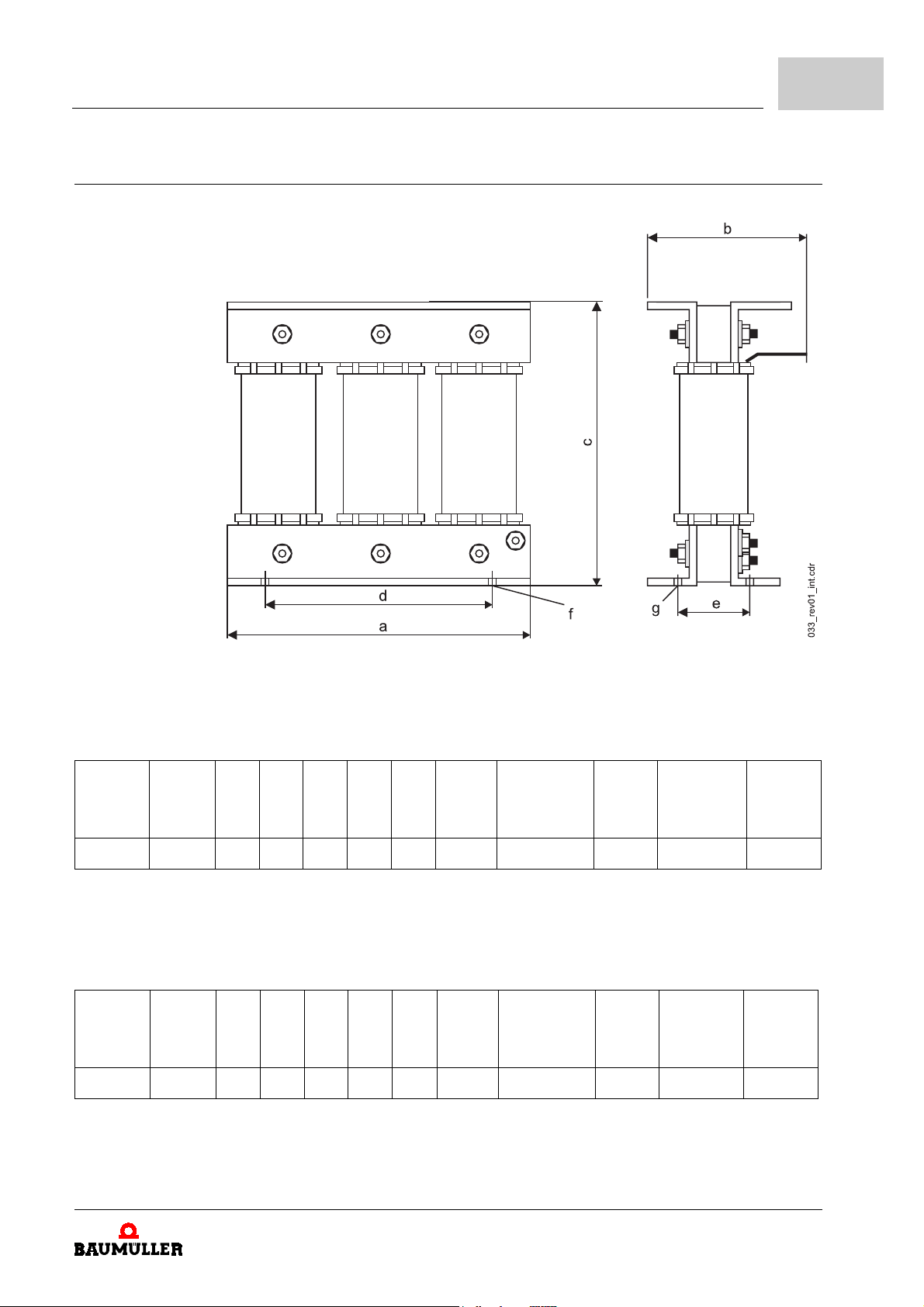
B.4 Line reactors
Accessories
B
figure 29: Line reactor
m
Three-phase line reactors for 400 V mains input voltage,
TA = 55 °C max.,Uk = 4 % / 4.8 %,
UN = 400 V, 50/60 Hz, with flat terminal IP 00
Reactor
DR3-40-4
- 0 400 400 310 220 260 280 131 11 x 18 40 x 4 ∅ 14 45,0 180 00101921
Rated
d. c.
current
A
a
b
c
d
e
mm
mm
m
Three-phase line reactors for 500 V mains input voltage,
mm
mm
mm
f x g
mm
TA = 55 °C max.Uk = 4 % / 4.8 %,
Flat terminal
∅
mm x mm
Weight
kg
Power consumption
W
Article
number
UN 420 to 500 V, 50/60 Hz, IP 00
Reactor
DR3-50-4
- 0 400 400 360 230 315 300 150 9 x 14 40 x 5 ∅ 14 73,0 225 00101931
Rated
d. c.
current
A
a
b
c
d
e
mm
mm
mm
mm
mm
f x g
mm
Flat terminal
∅
mm x mm
Weight
kg
Power consumption
W
Article
number
Manual Single Power Unit BUM64S/A/F
Document no.: 5.01056.03
89
of 118
Page 90

B.5
B.5 EMC accessories
EMC accessories
mains net filter rated mains input current
BFN 3-1-270 270 A (for BUM64 with a output power of 132 kW)
BFN 3-1-250 250 A (for BUM 63T at rated operation)
BFN 3-1-180-001 180 A (for BUM 63 at rated operation)
BFN 3-1-130-001 130 A
1)
depending on application. Choose mains net filter in such a way, that the occurring mains input current is
lower than the rated mains input current of the mains net filter.
1)
90
of 118
Manual Single Power Unit BUM64S/A/F
Document no.: 5.01056.03 Baumüller Nürnberg Electronic GmbH & Co. KG
Page 91

C
In this section we provide general information about EC directives, the CE symbol and the
Declaration of Conformity/by Manufacturer.
C.1 What is an EC directive?
EC directives specify requirements. The directives are written by the relevant bodies within the EU (which used to be called the EC, and the EEC before that, hence the now illogical term EC directive), and are implemented by all the member countries of the EU in
national law. In this way the EC directives guarantee free trade within the EU.
An EC directive only contains essential minimum requirements. You will find detailed requirements in standards, to which references are made in the directive.
D
ECLARATION OF
D
ECL. BY
A
PPENDIX
C
ONFORMITY
M
ANUFACTURER
UL-
C -
CERT
/
/
.
C.2 What the CE symbol indicates
a) The CE marking symbolizes conformity to all the obligations incumbent on manufacturers for the product by virtue of the Community directives providing for its affixing.
…
b) The CE marking affixed to industrial products symbolizes the fact that the natural or
legal person having affixed or been responsible for the affixing of the said marking has
verified that the product conforms to all the Community total harmonization provisions
which apply to it and has been the subject of the appropriate conformity evaluation pro
cedures.
…
Council Decision 93/465/EEC, Annex I B. a) + c)
We affix the CE mark to the equipment and to the documentation as soon as we have
established that we have satisfied the requirements of the relevant directives.
Manual Single Power Unit BUM64S/A/F
Document no.: 5.01056.03
-
91
of 118
Page 92

C.3
C.3 Definition of the term Declaration of Conformity
Definition of the term Declaration of Conformity
All converters and control systems supplied by the Baumüller Nürnberg Electronic GmbH
& Co. KG satisfy the requirements of 73/23/EEC (Low Voltage Directive).
Provide this Baumüller equipment is subjected to normal use in your machinery you can
assume that the equipment satisfies the requirements of 73/23/EEC.
Compliance with 89/336/EEC (EMC Directive) depends on how the equipment is installed. Since you are performing installation yourself, it is you who are responsible for complying with 89/336/EEC.
We will provide you with support in the form of EMC information. You will find this information in the operating instructions of the b maXX 4400 basic unit. When you have complied with all the requirements we impose in this documentation, you can assume that the
drive satisfies the requirements of the EMC Directive.
To enable you to market your machine within the EU, you must be in possession of the
following:
m
Conformity mark (CE mark)
m
Declaration(s) of Conformity regarding the directive(s) relevant to the machine
A Declaration of Conformity as defined by this documentation is a declaration that the
electrical equipment brought into circulation conforms to all the relevant fundamental
safety and health requirements.
By issuing the Declaration of Conformity in this section the Baumüller Nürnberg Electronic
GmbH & Co. KG declares that the equipment conforms to the relevant fundamental safety
and health requirements resulting from the directives and standards which are listed in
the Declaration of Conformity.
C.4 Definition of the term Declaration by Manufacturer
A Declaration by Manufacturer as defined by this documentation is a declaration that the
machine/safety component brought into circulation conforms to all the relevant funda
mental safety and health requirements.
By issuing the Declaration of Conformity in this section the Baumüller Nürnberg Electronic
GmbH & Co. KG declares that the equipment conforms to the relevant fundamental safety
and health requirements resulting from the directives and standards which are listed in
the Declaration of Conformity .
The Baumüller equipment is integrated into a machine. For health and safety, of the users
for example, it is important for the entire machine to conform to all the relevant fundamen
tal safety and health requirements. For this reason the Baumüller Nürnberg Electronic
GmbH & Co. KG. For this reason the Baumüller Nürnberg Electronic GmbH & Co. KG
draws attention in the Declaration by Manufacturer to the fact that it is prohibited to put
the machine as a whole into operation before it has been declared that the machine con
forms to the provisions of the Machinery Directive.
-
-
-
92
of 118
Manual Single Power Unit BUM64S/A/F
Document no.: 5.01056.03 Baumüller Nürnberg Electronic GmbH & Co. KG
Page 93
Declaration of Conformity / Decl. by Manufacturer / UL-cert.
C.5 Declaration of Conformity
EG-Konformitätserklärung
Declaration of Conformity
C
gemäß EG-Richtlinie 73/23/EG (Niederspannung) vom 19.02.1973
geändert durch: 93/68/EWG vom 22.07.1993
in accordance with EC directive 73/23/EG (low voltage) dated 19.02.1973
changed by: 93/68/EWG dated 22.07.1993
BUM64A - XXX/XXX - XX - X - X - XXX
BUM64F - XXX/XXX - XX - X - X - XXX
BUM64S - XXX/XXX - XX - X - X - XXX
Das obige Gerät wurde entwickelt und konstruiert sowie anschließend gefertigt in Übereinstimmung mit
o.g. EG-Richtlinie und u.g. Normen in alleiniger Verantwortung von:
the unit specified above was developed and constructed as well as manufactured in accordance with
the above mentioned directive and the standards mentioned below under liability of:
Baumüller Nürnberg Electronic GmbH & Co. KG, Ostendstr. 80 - 90, D-90482 Nürnberg
Berücksichtigte Normen - standards complied with:
Norm / standard
EN 50178 Ausrüstung von Starkstromanlagen mit elektrischen Betriebsmitteln
Electronic equipment for use in power installations
EN 60204-1 Sicherheit von Maschinen - Elektrische Ausrüstung von Maschinen
Safety of machinery - Electrical equipment of machines
EN 60529 Schutzarten durch Gehäuse (IP Code)
Degrees of protection provided by enclosures (IP Code)
HD 625.1 51 Isolationskoordination für elektrische Betriebsmittel in Niederspannungsanlagen
Insulation coordination for equipment within low-voltage systems
Nürnberg, 17.12.2003
_________________________ _________________________
Dr. Peter Kreisfeld Dr. Heidrich
Geschäftsführer Entwicklungsleiter
Head Division Head of development Seite 1 von 1 / page 1 of 1
Manual Single Power Unit BUM64S/A/F
Document no.: 5.01056.03
93
of 118
Page 94
Declaration of Conformity / Decl. by Manufacturer / UL-cert.
C.6 Declaration by Manufacturer
EG-Herstellererklärung
Declaration by Manufacturer
gemäß EG-Richtlinie 98/37/EG (Maschinen) vom 22.06.1998
geändert durch: 98/79/EG vom 27.10.1998
C
in accordance with EC directive 98/37/EG (machinery) dated 22.06.1998
changed by: 98/79/EC dated 27.10.1998
BUM64A - XXX/XXX - XX - X - X - XXX
BUM64F - XXX/XXX - XX - X - X - XXX
BUM64S - XXX/XXX - XX - X - X - XXX
Die Inbetriebnahme der Maschine, in die dieses Gerät eingebaut wird, ist untersagt bis die Konformität
der Maschine mit der obengenannten Richtlinie erklärt ist.
The machinery into which this unit is to be incorporated must not be put into service until the machinery
has been declared in conformity with the provisions of the directive mentioned above.
Bei der Entwicklung und Konstruktion des Geräts wurden folgende Normen beachtet:
The development and construction of the unit is complied with following standards:
Norm / standard
EN 60204-1 Sicherheit von Maschinen - Elektrische Ausrüstung von Maschinen
Safety of machinery - Electrical equipment of machines
Baumüller Nürnberg Electronic GmbH & Co. KG, Ostendstr. 80 - 90, D- 90482 Nürnberg
Nürnberg, 17.12.2003
_________________________ _________________________
Dr. Peter Kreisfeld Dr. Heidrich
Geschäftsführer Entwicklungsleiter
Head Division Head of development Seite 1 von 1 / page 1 of 1
Manual Single Power Unit BUM64S/A/F
Document no.: 5.01056.03
94
of 118
Page 95

Declaration of Conformity / Decl. by Manufacturer / UL-cert.
C.7 UL-certification
UL is a mark of conformity, which is assigned from Underwriters Laboratories Inc. (www.ul.com), an
American company. The UL-certification is not statutory regulated, but takes place voluntarily.
In order to be allowed to mark equipments and components with the UL-mark of confomity, tests must
have to be done, which are attended and documentated by an UL-inspector. Only if all necessary tests
have been passed and regular product monitoring at the production process of the equipment or the
components has been passed without objections, the UL-mark of conformity may be attached to the
equipment under test.
Line filters of the company Baumüller Nürnberg Electronic GmbH & Co. KG are checked in accordance
of the UL-standard UL 508C (UL-Standard for Safety for Power Conversion Equipment) and are record
ed under the category control number NMMS. The product- and test description is recorded under
file-no. E179860.
Only if all necessary tests have been completely carried out the c-mark may be attached to the equipments or components. If single tests have not already taken place at the manufacturer´s, but are carried
out not until at the user´s, then only the
With products of the Baumüller Nürnberg Electronic GmbH & Co. KG all tests are already completed at
the UL-certification process, so that they may be marked with the
In case with the UL-certification process also standards of the CSA(Canadian Standard Association)
are considered, then instead of the c
uct.
With products of the company Baumüller Nürnberg Electronic GmbH & Co. KG. the CSA-standard
Norm C 22.2 was considered, that´s why they are marked with the
If products of Baumüller Nürnberg Electronic GmbH & Co. KG. are mounted into an UL-certified installation, then certain application-, mounting- and installation notices must be considered, which are upon
the functioning of the device. We have marked these notes in the manual with „UL 508C ...“. Only if you
follow these notes and apply to them you may go by it, that the installation has been mounted UL-con
form.
C
-
u
-mark may be attached.
- or u-mark the
c
or
c
c
-mark.
U
-mark may be attached to the prod-
c
-mark.
c
-
Manual Single Power Unit BUM64S/A/F
Document no.: 5.01056.03
95
of 118
Page 96

C.7
UL-certification
96
of 118
Manual Single Power Unit BUM64S/A/F
Document no.: 5.01056.03 Baumüller Nürnberg Electronic GmbH & Co. KG
Page 97

D
A
PPENDIX
In this chapter you will find an overview of the technical specifications. Some of these data we
have been using before in the previous chapters at the respective places.
D - T
ECHNICAL SPECIFICATIONS
Manual Single Power Unit BUM64S/A/F
Document no.: 5.01056.03
97
of 118
Page 98
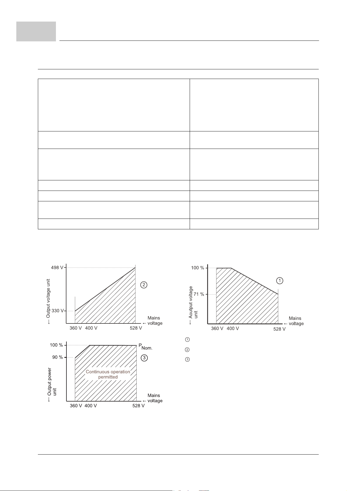
D.1
Requirements on the power supply
D.1 Requirements on the power supply
Mains input voltage network Industrial system with solid- or low-impedant
grounded neutral system (TN-mains or TT-
mains)
Industrial system with none- or high-impedant
grounded neutral system (IT-mains)
Industrial system with solid or low-impedant
grounded corner (∆-grounded-mains)
Total inductance at the unit connection (sum of mains
min. Uk = 4 % max. Uk = 6 %
inductance and line reactor inductance)
Mains input voltage/-frequency
1) 2)
unit (UAC)
ventilator
8)
(UAC)
min. 3 x 360 V -0% / 48 to 62 Hz
max. 3 x 528 V +0% / 48 to 62 Hz
min. 207 V -0% / 48 to 62 Hz
max. 243 V +0% / 48 to 62 Hz
Harmonics (mains input voltage) THD < 10%
Dissymmetry of mains input voltage max. 3%
Voltage dip depth of voltage dip < 40 %, area < 250 % x
degree
Control voltage
1)
At voltage interrupts (0.7UB > U > 0.1UB for t > 0.1 sec.) (U=mains input voltage) the error “Phase failure“ or “Network failure“ is generated (see also
2)
The rated voltage is 400 V. If mains input voltages below 400 V are used the power output of the appliance decreases (see curves).
6)
(UDC) + 24 V -10 % / +20 % 7)
ZMonitoring functions– from page 69
).
3)
4)
5)
3)
EN 61800-3, chapter 5.2.1
4)
IEC 1000-2-4, table 1, Class 3
5)
EN 61800-3, chapter 5.2.2
98
of 118
Manual Single Power Unit BUM64S/A/F
Document no.: 5.01056.03 Baumüller Nürnberg Electronic GmbH & Co. KG
curve “output current“
curve “output voltage“
If you multiply the output current by the output
voltage you will get the output power of the appliance.
In order to achieve the given curve/area, it is necessary, that you reduce the output current between
400 and 528 volts.
Page 99
Technical specifications
6)
The supply voltage must meet PELV (EN 50178, chapter 3.49) or SELV (EN 50178, chapter. 3.70) requirements.
At supply voltages < 24 V the ventilation power output is reduced.
Therefore it may be also necessary to reduce the output currents as well.
7)
EN 61131-2:1994, Table 7
8)
for cooling variants S and A only
D.2 Required environmental conditions
Transport temperature range - 30 °C to + 70 °C
Transport climatic class 2 K 3
Storage temperature range - 30 °C to + 70 °C
Storage climatic class 1 K 4
Operational surrounding outside populated areas
Operation temperature range min. 0 °C up to max. 55 °C
Operation climatic class 3 K 3
Mounting height
4)
up to 2000 m above sea level
(rated service at 1000 m above sea level)
Relative humidity (operation) 5 % to 85 % no condensation
1)
1)
1)
2)
2)
D
1)
Ionizing and non-ionizing radiation no limits
Vibration, shock and continuous shock max. 1 g
Degree of pollution 2
Air ventilation temperature
Water cooling temperature
8)
7)
min. 0 °C to max. 55 °C
min. “Air ventilation temperature 9)“
5)
6)
3)
up to max. 60 °C
Air ventilation through appliance (without heatsink)
Air ventilation through heatsink
Cooling water flow rate
Cooling water pressure
7)
7)
min. 4 l/min. up to max. 10 l/min.
300 m3 / h
800 m3 / h
max. 6 bar
Temperature difference (Coolant intake to -outlet) 6 K at 4 l/min at rated operation
Pressure loss at water cooler
1)
EN 50178, table 7
2)
when operated in populated areas you will have to experience high frequency disturbances (acc. to EN 61800-3, 6.4.2.1)
3)
40 °C is the rated temperature
7)
variant F: 1.15 bar at 4 l/min
Manual Single Power Unit BUM64S/A/F
Document no.: 5.01056.03
99
of 118
Page 100
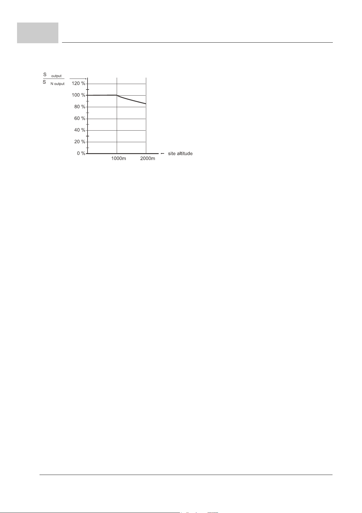
D.2
4)
5)
6)
7)
8)
9)
Required environmental conditions
characteristic curve: power output of appliance in dependence of mounting height at normal pressure
EN 50178, chapter 9.4.3.2
EN 50178, table 2
As coolant use clear, suspended matter- and dirt-free, desalinated and demineralized water. The water may hold a maximum of 100
ppm (0.01%) natrium chloride (salinity). Mix in an anticorrosive. The total water hardness must be between 8° and 14° dH (1° dH = 0.179
mmol Ca
Air inside and outside switching cabinet.
Air inside switching cabinet.
2+
/l). A pH-value between 6.5 and 7.5 must be kept. Use a closed loop coolant circulation!
100
of 118
Manual Single Power Unit BUM64S/A/F
Document no.: 5.01056.03 Baumüller Nürnberg Electronic GmbH & Co. KG
 Loading...