

Page 1
BUM 62 T
Mono Power Unit
Manual
E
5.99009.03
Page 2

Title Manual
Product Mono Power Unit BUM 62 T
Version 5.99009.03
Status 2005-02-03
Copyright These operating instructions may be copied by the owner in
any quantity but only for internal use. For other purposes
these operating instructions and extracts thereof must not
be copied or reproduced.
Use and disclosure of information contained in these operating instructions are not permitted.
Designations and company marks contained in these operating instructions may be brand names, the use of which by
third parties for their own purposes may violate the rights of
the holders.
Obligatory These operating instructions are part of the equipment/ma-
chine. These operating instructions must be available to the
operator at all times and must be in a legible condition. If the
equipment/machine is sold or moved to a different location
these operating instructions must be passed on by the own
er together with the equipment/machine.
After any sale of the equipment/machine this original and all
copies must be handed over to the buyer. After disposal or
any other end of use this original and all copies must be de
stroyed.
-
-
When the present operating instructions are handed over,
corresponding sets of operating instructions of a previous
version are automatically invalidated. Please notice that
specifications/data/information are current values accord
ing to the printing date. These statements are not legally
binding according to the measurement, computation and
calculations.
Baumüller Nürnberg GmbH reserves the right, in developing
its products further, to change the technical specifications
and the handling of the products concerned without prior no
tice.
No liability can be accepted concerning the correctness of
the operating instructions unless otherwise specified in the
General Conditions of Sale and Delivery.
Manufacturer Baumüller Nürnberg GmbH
Ostendstr. 80 - 90
D-90482 Nürnberg
Germany
Tel. +49 9 11 54 32 - 0 Fax: +49 9 11 54 32 - 1 30
www.baumueller.de
-
-
Page 3

Table of contents
TABLE OF CONTENTS
1 Safety notes ........................................................................................................ 7
2 Introduction ....................................................................................................... 11
3 Technical data ................................................................................................... 13
3.1 Table of technical data ......................................................................................................... 13
3.2 Type key ............................................................................................................................... 15
3.3 Block diagram ....................................................................................................................... 16
4 Transportation, Unpacking .............................................................................. 17
5 Assembly ........................................................................................................... 19
5.1 Free space ............................................................................................................................ 19
5.2 Installation information .......................................................................................................... 20
6 Installation ......................................................................................................... 23
6.1 Danger information ............................................................................................................... 23
6.2 EMC information ................................................................................................................... 25
6.3 Applicable standards ............................................................................................................ 31
6.4 Safety relay ........................................................................................................................... 33
6.4.1 Methods to avoid an unexpected starting .................................................................................... 33
6.4.2 Safety categories ......................................................................................................................... 34
6.4.3 The safety relay ........................................................................................................................... 34
6.4.4 Service time ................................................................................................................................. 38
6.5 Connection diagram ............................................................................................................. 39
6.6 Terminal strips and plug-in terminals .................................................................................... 40
6.6.1 Power connections ...................................................................................................................... 40
6.6.2 Control connections ..................................................................................................................... 42
6.6.3 Controller connection ................................................................................................................... 46
6.6.4 Safety relay (as an option) ........................................................................................................... 46
6.7 Accessories .......................................................................................................................... 47
7 Commissioning ................................................................................................. 49
7.1 Danger information ............................................................................................................... 49
7.2 Operation .............................................................................................................................. 52
7.3 Monitoring functions and their messages ............................................................................. 52
7.3.1 Ready for operation ..................................................................................................................... 53
7.3.2 Monitoring functions ..................................................................................................................... 55
7.3.3 Messages via LEDs ..................................................................................................................... 60
7.3.4 Messages via relay contacts ........................................................................................................ 61
8 Maintenance ...................................................................................................... 63
8.1 Maintenance information ...................................................................................................... 63
8.2 Environmental conditions ..................................................................................................... 64
8.3 Recommissioning ................................................................................................................. 64
8.4 Disposal ................................................................................................................................ 65
Mono Power Unit BUM 62 T 3
Baumüller Nürnberg GmbH 5.99009.03
Page 4

Table of contents
9 Appendix ........................................................................................................... 67
9.1 Manufacturer Declaration ..................................................................................................... 67
9.2 Declaration of Conformity ..................................................................................................... 68
9.3 General Conditions of Sale and Delivery .............................................................................. 69
9.4 Index ..................................................................................................................................... 72
4 Mono Power Unit BUM 62 T
5.99009.03 Baumüller Nürnberg GmbH
Page 5

ABBREVIATIONS
AC Alternating current
AM Asynchronous motor
BUM Baumüller
Mono Power Unit
BUS Baumüller
Power Module
DC Direct current
DIN Deutsches Institut für Normung e.V.
(German Standardization Authority)
EMC Electromagnetic compatibility
EN European Standard
MC Main contactor
IPM Intelligent power module
a.m.s.l. above mean sea level
PELV Protective extra-low voltage
Abbreviations
SELV Safe extra-low voltage
PE Protective earth
SM Synchronous motor
ZK DC link
Mono Power Unit BUM 62 T 5
Baumüller Nürnberg GmbH 5.99009.03
Page 6

6 Mono Power Unit BUM 62 T
5.99009.03 Baumüller Nürnberg GmbH
Page 7
Safety notes
1 SAFETY NOTES
Introductory remarks
During operation, the principles on which the converter and motor work, lead to leakage currents to earth
which are dissipated by use of the specified protective earth connections which may result in a currentoperated e.l.c.b. on the input side blowing prematurely.
A DC component in the fault current may occur in the event of a short-circuit to frame or earth fault which
could make triggering of the higher-level current-operated e.l.c.b. more difficult or even impossible.
Connection of the current controller to the mains using only the current-operated e.l.c.b. is prohibited
(preliminary standard EN 50178 / VDE 0160 /11.94, sections 5.2.11 and 5.3.2.1).
The units are protected against direct contact by being installed into common switching cabinets which
meet the minimum protection requirements according to EN 50178 / VDE 0160 / 11.94, section 5.2.4.
Sheets of plastic covering the control electronics, the power stage and the device connection,
additionally prevent accidental contact during commissioning and casual use of control elements located
close to the equipment.
(DIN VDE 0106 Part 100, Accident Prevention Regulation VBG4 ”Electrical Systems and Equipment).
The protective measures and safety regulations according to DIN/VDE are binding for personal security.
Neglecting to fit PE connections on the equipment or the motor will result in serious personal injury and/
or considerable damage of property.
General information
These operating instructions contain the information required for the application as directed of the
products described herein. The document is intended for specially trained, skilled personnel who are
well-versed in all warnings and maintenance activities. The units are manufactured using the state-ofthe-art technology and are safe in operation. They can be installed safely, commissioned and function
without problems if the safety information below is observed.
DANGER
When operating this electrical unit, some parts of the equipment always carry dangerous voltage.
Ignoring these safety instructions and warnings may result in death, serious personal injury and/or
damage of property.
Only qualified personnel who are familiar with the safety information, mounting, operation and
maintenance instructions may carry out work on this unit.
Mono Power Unit BUM 62 T 7
Baumüller Nürnberg GmbH 5.99009.03
Page 8
Safety notes
Danger information
One the one hand, the information below is for your own personal safety and on the other to prevent
damage to the described products or units connected to it.
In the context of the operating instructions and the information on the products themselves, the terms
used have the following meanings:
DANGER
This means that death, severe personal injury or considerable property damage will occur,
unless appropriate safety measures are taken.
WARNING
This means that death, severe personal injury or considerable property damage may occur,
unless appropriate safety measures are taken.
NOTE
This draws your attention to important information about the product, handling of the product or to
a particular section of the documentation.
Qualified personnel
Qualified personnel in the sense of the safety-relevant information in this document or on the products
themselves, qualified personnel are considered to be persons who are familiar with setting up, mounting,
commissioning and operating the product and who have qualifications appropriate to their activities.
y Trained or instructed or authorised to commission, ground and mark circuits and equipment in
accordance with recognized safety standards.
y Trained or instructed in accordance with recognized safety standards in the care and use of
appropriate safety equipment.
8 Mono Power Unit BUM 62 T
5.99009.03 Baumüller Nürnberg GmbH
Page 9
Safety notes
Application as directed
WARNING
You may only use the unit/system for the purposes specified in the operating instructions and in
conjunction with the third-party equipment and components recommended or authorised by
BAUMÜLLER NÜRNBERG GmbH.
For safety reasons, you must not change or add components on/to the unit. The operator must report
immediately any changes that occur which adversely affect the safety of the unit/system.
Voltage test
BAUMÜLLER carries out a voltage test according to EN 50178 / VDE 0160 /11.94, Section 9.4.5 for
each unit.
Subsequent high-voltage tests must only be carried out by BAUMÜLLER NÜRNBERG GmbH.
WARNING
If you want to carry out high-voltage tests for complete switch cabinet installations, disconnect all
cables from BAUMÜLLER units prior to the test.
Mono Power Unit BUM 62 T 9
Baumüller Nürnberg GmbH 5.99009.03
Page 10

Safety notes
10 Mono Power Unit BUM 62 T
5.99009.03 Baumüller Nürnberg GmbH
Page 11

Introduction
2 INTRODUCTION
The power units designated BUM 62 T are used for the upper power range.
Supply part (converter)
The supply part (mains side) for the generation of the DC link voltage is an uncontrolled diode bridge.
To reduce the peak making current (deburdening during switch-on), the DC link capacitors are charged
via a charge resistor which is bridged by a thyristor after switching-on.
If the typical motor power of the converter on the motor side (see electrical data) is not fully used, e.g.,
because the power of the connected motor is smaller, the performance of the supply current controller
can be used for the connection of other power modules of the BUS 6 series.
The total of all motor powers occurring at the same time must not be higher than the typical motor power.
Starting current load relief
If precautions are not taken, the DC link capacitors produce inadmissibly-large charging current surges
from the mains. In order to avoid these surges, the starting current is limited by a load relief device.
To this purpose, a resistance is integrated into the charging circuit. The resistance limits the charging
current (with the exception of temporary mains failure) and is bypassed once the DC link is charged.
The cycle time for connect the unit in circuit again is ≥3 min.
If using an additional external capacitor at the DC (external capacity ≥ 500 µF) the cycle time is
increased
Mono Power Unit BUM 62 T 11
Baumüller Nürnberg GmbH 5.99009.03
Page 12

Introduction
Brake switch
The energy which is generated in the generator mode, is dissipated by the brake switch (brake chopper)
and an external regenerative resistor.
Inverter
The inverter on the motor side consists of the IGBT power part and the corresponding sensors. The
sensors supply measuring signals for the closed-loop control and also ensure the self-protection of the
power electronics.
The inverter is triggered by the controller used.
Baumüller rack modules are provided for the control. The drives can therefore be adapted to different
applications.
Controller
The BUM 62 T only operates in conjunction with an additional controller. The controller types are
equipped with modules. A separate description is available for the operation of the controllers.
12 Mono Power Unit BUM 62 T
5.99009.03 Baumüller Nürnberg GmbH
Page 13

Technical data
3 TECHNICAL DATA
3.1 Table of technical data
BUM 62 T - 100 / 130 - ...
Connection voltage (mains)
Supply voltage
2)
1)
3 x 400 V
3 x 460 V
+ 24 VDC -10% / +20 % (72W)
Continuous input power max. 50 kVA
Rated DC link voltage
3)
DC link capacity (internal) 1700 µF
DC link capacity (external) max. 500 µF
Cycle time for connect the unit in circuit again
(without additional DC link capacitors)
Output voltage
Output frequency
4)
5)
Continuous output power
Continuous output power
Continuous motor power
Continuous motor power
Rated output current
Rated output current
Peak output current
Peak output current
6) 7) 8)
6) 7) 8)
6) 7) 9)
6) 7) 9)
at 4 kHz
at 8 kHz
at 4 kHz
at 8 kHz
at 4 kHz
at 8 kHz
at 4 kHz
at 8 kHz
10)
10)
10)
10)
10)
10)
10)
10)
3 x 0 VAC ... 3 x (conn. volt. -30 V)
0 Hz. ...300 Hz
Connection power DC link connection 36 kW
External chopper current max. 73 A
Internal chopper resistor External chopper resistor ≥ 11 Ω
Application threshold of regenerative resistor 750 V
Ambient temperature range (operation)
11)
min. 0 °C .... max. 55 °C
40 °C (nominal temperature)
Power loss 3) Connect. (mains)
Supply
Type of protection IP 20
Installation height
12)
max.
relative humidity 15 % ... 85 % no condensation.
Temperature range for transport - 30 °C ... + 70 °C
Temperature range for storage - 30 °C ... + 70 °C
Dimensions (W x H x D) 264 x 560 x 280 mm
Weight without controller 30 kg
±15% 50 Hz
AC
+10% -25% 60 Hz
AC
DC
540 V
≥3 min
max. 62 kVA
max. 50 kVA
max. 43 kW
max. 35 kW
100 A
75 A
130 A
97 A
1400 W
max. 72 W
1000 m a.m.s.l.
Mono Power Unit BUM 62 T 13
Baumüller Nürnberg GmbH 5.99009.03
Page 14
Technical data
1. Voltage difference between phases must no exceed +/- 1.0 %.
2. According to EN 61131-2 (Table 5).
With a supply voltage < 24 V the fan power is reduced. Therefore, it may be necessary to reduce the
output current additionally.
3. All ratings refer to a connection voltage of 400 V and a supply voltage of 24 V.
4. The output voltage is a pulse-commutated DC. The setting range refers to the r.m.s. value of the
fundamental wave.
5. The output frequency depends on the controller used.
6. R.m.s. value at an ambient temperature of 40 °C.
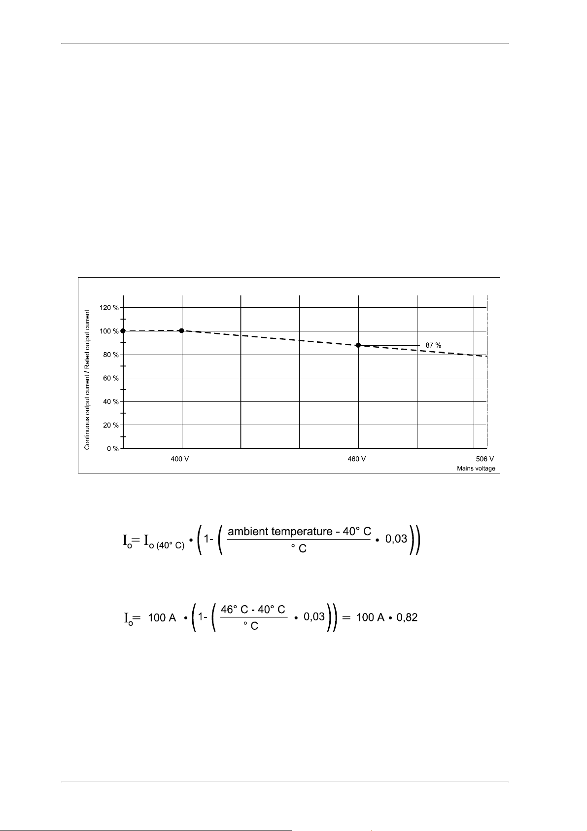
7. The unit provides the rated/maximum output current up to the connection voltage. When the input
voltage exceeds the rated voltage, reduce the output currents at constant output power
proportionally.
Characteristic 1: Output currents in relation to the connection voltage.
8. The rated output current must be reduced between 40 °C and 55 °C. The rated output current is
calculated according to the following formula:
Example: Rated output current = 100 A, ambient temperature = 46 °C.
The rated output current must therefore be reduced to: 82 A
9. Maximum duration of the peak output current is 120 s. The duration depends on the motor current
and the temperature of the heat sink. See Technical Description/Operating Instructions of the
controller (V-controller: P139).
10. Chopping frequency of the inverter.
(see description parameter P103 in the description of the V-controller)
14 Mono Power Unit BUM 62 T
5.99009.03 Baumüller Nürnberg GmbH
Page 15
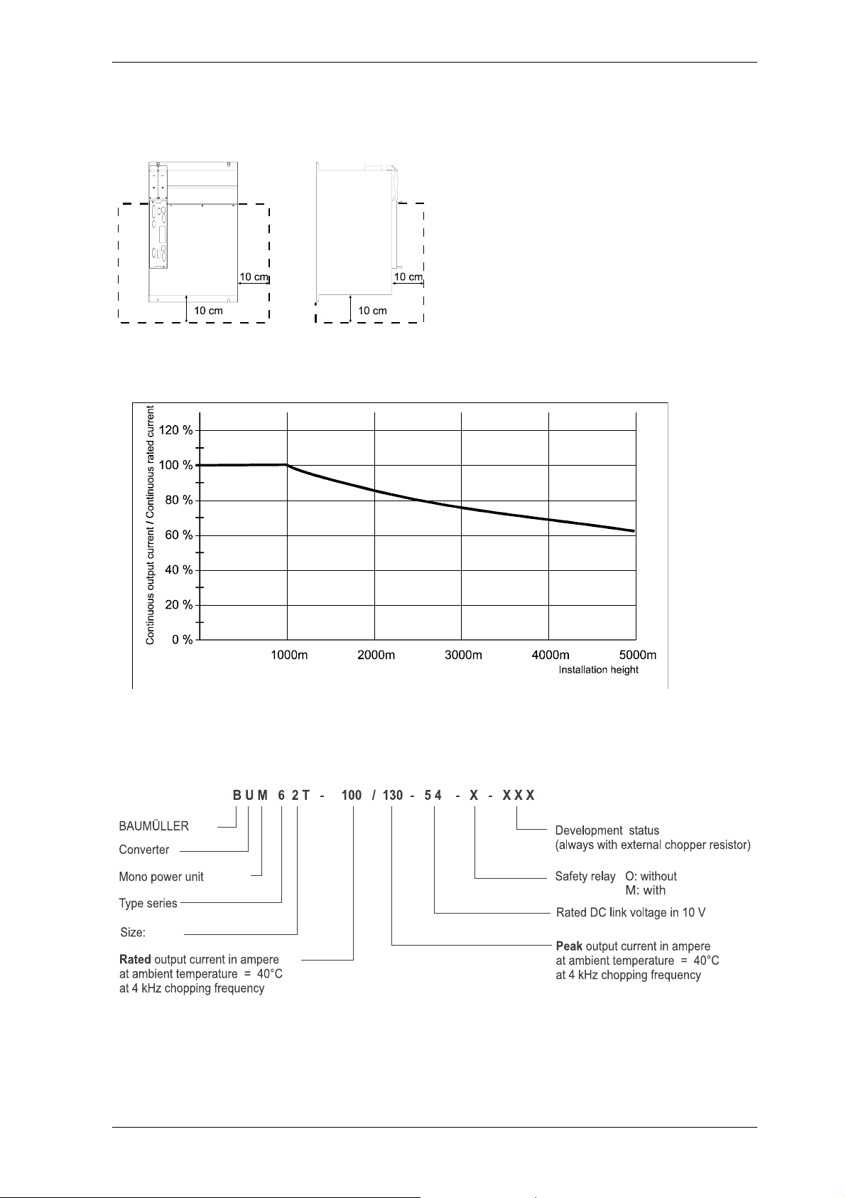
Technical data
11. The ambient temperature is determined as follows:
y Determine several measuring points
covering the entire area as illustrated at
a distance of 10 cm.
y Measure the temperature at these
measuring points.
The highest value is
the ambient temperature.
12. Characteristic 2: Values in relation to the installation height at normal air pressure.
3.2 Type key
Mono Power Unit BUM 62 T 15
Baumüller Nürnberg GmbH 5.99009.03
Page 16
Technical data
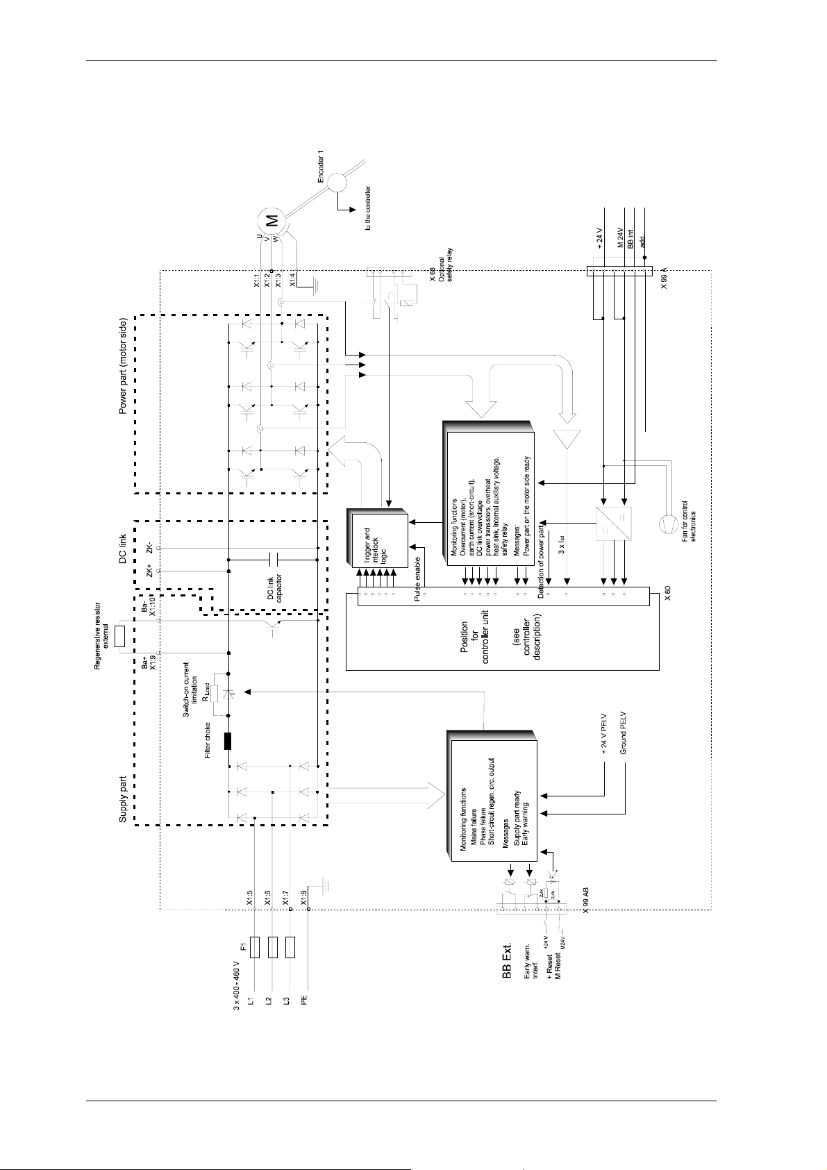
3.3 Block diagram
16 Mono Power Unit BUM 62 T
5.99009.03 Baumüller Nürnberg GmbH
Page 17
Transportation, Unpacking
4 TRANSPORTATION, UNPACKING
The units are packed at the factory in accordance with the order.
Avoid strong shaking during transportation and shocks, e.g. when setting the units down.
After unpacking the units and checking that the shipment is complete and undamaged, you can start
assembly.
The packing consists of fibreboard, corrugated cardboard and/or wood. It can be disposed according to
the local regulations.
Report any transport damage without delay.
DANGER
If you detect a transport damage on the unit, it must not be connected unless an appropriate voltage
test has been carried out.
Ignoring this information can result in death, severe personal injury or considerable damage to
material assets.
Mono Power Unit BUM 62 T 17
Baumüller Nürnberg GmbH 5.99009.03
Page 18

Transportation, Unpacking
18 Mono Power Unit BUM 62 T
5.99009.03 Baumüller Nürnberg GmbH
Page 19
Assembly
5 ASSEMBLY
WARNING
The user is responsible for the assembly of the unit described, the motor, and the other devices
according to the safety regulations (e.g. EN, DIN, VDE) and all other relevant nations or local
regulations concerning the conductor ratings and protection, grounding, disconnectors, overcurrent
protection, etc.
The following measures for ventilation must be strictly observed.
Otherwise, the unit may be overheated.
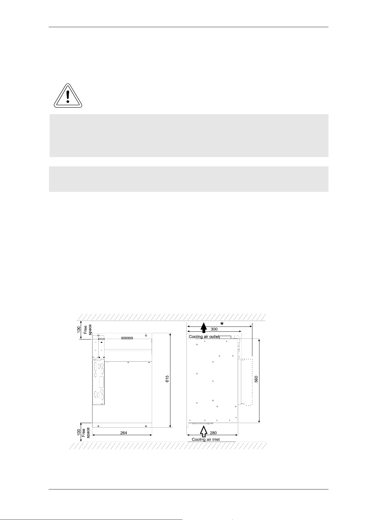
y Ensure sufficient cooling air and ventilation!
y Ventilation must be from the bottom to the top, ensure a free space above and below the unit (see
”Free space” on page 19).
y The rated power of the unit is possible only up to a specific ambient temperature! The power must
be reduced when higher temperatures occur (see
y Do not locate any other sources of heat above the unit.
y Pollution degree 3 and 4 according to EN 50178:1994 Section 5.2.15.2 must be avoided. The units
are suitable for the installation in closed operating rooms. (VDE 0558 Part 1a, Section 5.4.3.2.1 and
5.4.3.2.2)
”Table of technical data” on page 13).
5.1 Free space
The total depth depends on the controller dimensions!
*
Mono Power Unit BUM 62 T 19
Baumüller Nürnberg GmbH 5.99009.03
Page 20
Assembly
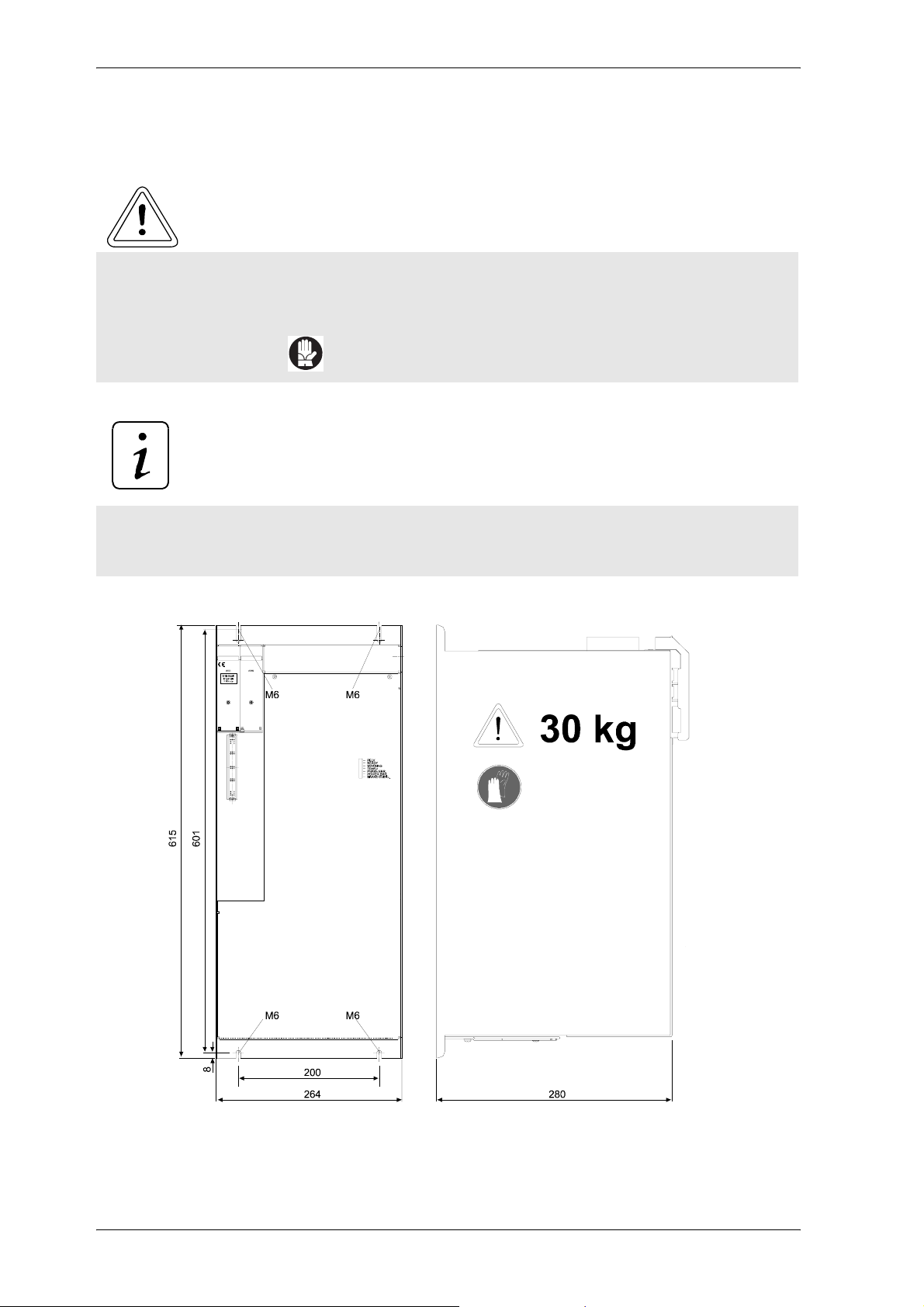
5.2 Installation information
WARNING
Inappropriate lifting can cause personal injury or damage to material assets.
Qualified personnel only may lift the unit using suitable equipment.
y Observe the weight of the unit!
y use protective gloves!
NOTE
y Always mount the unit vertically at the back panel of the switch cabinet.
y Arrange several units side by side
20 Mono Power Unit BUM 62 T
5.99009.03 Baumüller Nürnberg GmbH
Page 21
Installation
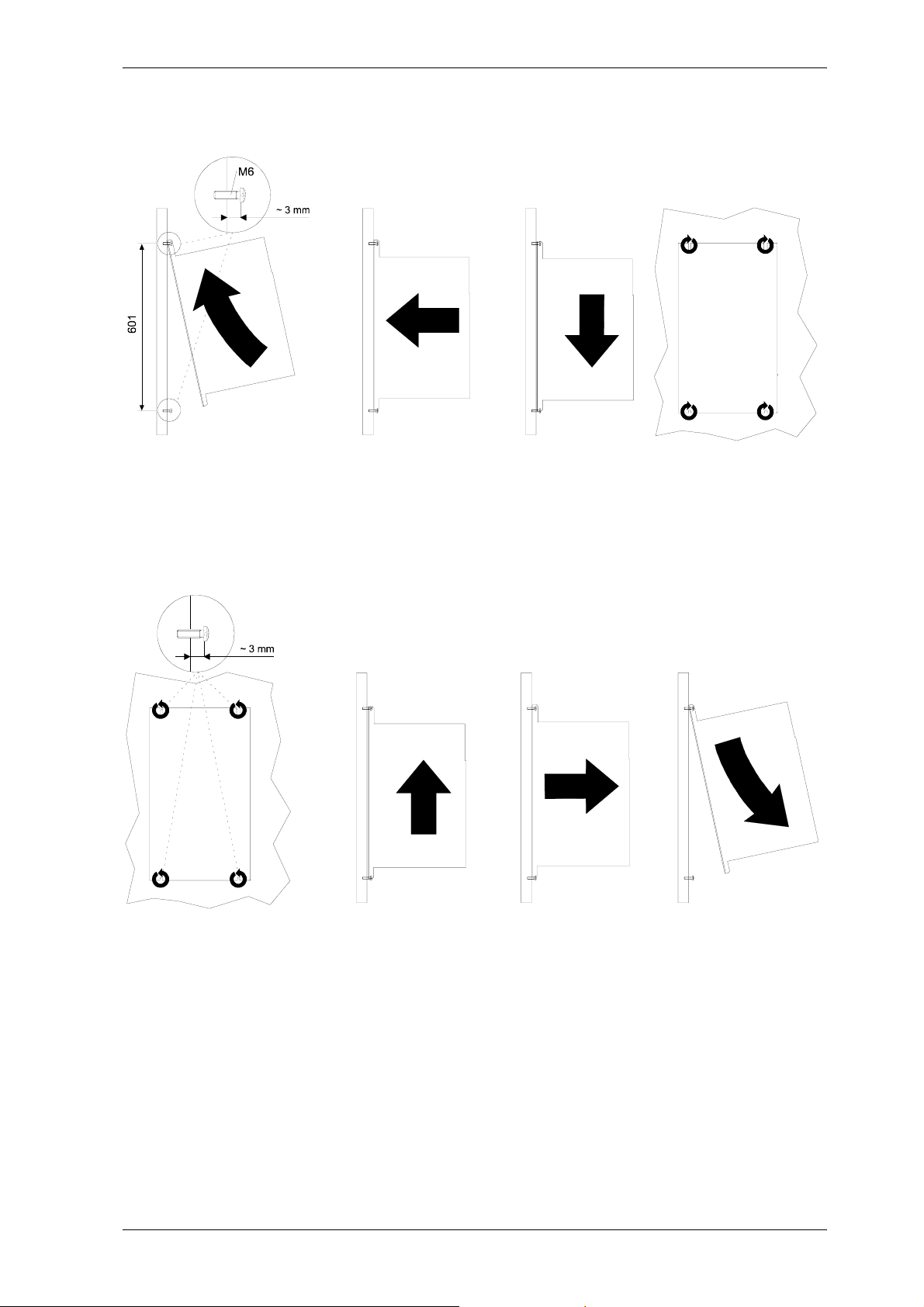
Assembly
Dismantling
Mono Power Unit BUM 62 T 21
Baumüller Nürnberg GmbH 5.99009.03
Page 22

Assembly
22 Mono Power Unit BUM 62 T
5.99009.03 Baumüller Nürnberg GmbH
Page 23
Installation
6 INSTALLATION
6.1 Danger information
WARNING
This device carries dangerous voltage and contains dangerous rotating parts (fans). Ignoring the
safety and warning information may result in death, severe personal injury and/or damage to material
assets.
The user is responsible for the assembly of the converter, the motor, the mains choke and the other
devices according to the safety regulations (e.g. DIN, VDE) and all other relevant nations or local
regulations concerning the conductor ratings and protection, grounding, disconnectors, overcurrent
protection, etc.
The protective measures and safety regulations according to DIN/VDE are binding for personal
security. If there are no PE connections on the unit, the commutation choke or the motor, personal
injury may be caused since the surface may carry hazardous voltage.
During operation, the principles on which the converter and motor work, lead to leakage currents to
earth which are dissipated via specified protective earth connections and which may result in a currentoperated e.l.c.b. on the input side blowing prematurely.
A DC component in the fault current may occur in the event of a short-circuit to frame or earth fault
which makes a triggering of the higher-level current-operated e.l.c.b. more difficult or even impossible.
Make the PE connection according to DIN EN 60204 / VDE 0113 Part 1 / 06.93, Section 8.2.2.
considering EN 50178 / VDE 0160/11.94, Sections 5.3.2.1 and 8.3.4.4.
Before commissioning check whether the plastic covers over the live parts (power part connections)
are in place.
Malfunction of the drive
During the initial commissioning, a faulty or uncontrolled movement of the driven machine elements
cannot be excluded. Therefore, proceed with particular care.
Mono Power Unit BUM 62 T 23
Baumüller Nürnberg GmbH 5.99009.03
Page 24
Installation
WARNING
Prior to connecting the drive, carefully check all higher-level safety equipment for perfect functioning,
to avoid personal injury.
Special care must be taken when touching the drive shaft directly or indirectly (by hand). This is
permissible only when the shaft is at standstill and the converter is de-energized. Machine parts which
are freely accessible during operation (shafts, fans, etc.) must be covered.
Protection against contact according to Paragraph 4 Section 4 VBG 4
Protection against direct contact comprises all measures against danger which can result from
touching the active parts of electrical equipment.
The active parts must therefore be protected from direct contact by insulation, design, position,
arrangement or firmly installed facilities. Protection refers to common covers, barriers and procedures
which ensure that persons are prevented from touching live, active parts.
Switch cabinet must have emergency stop facilities using which all voltages causing dangerous
situations, can be switched off. This does not include equipment which, if switched off, would cause
another dangerous situation. The releasing element for the emergency stop facility must be arranged
such that it can easily be reached in case of danger. In the event of work which is considerably more
dangerous that usual, another person must be present.
The operator must ensure that unauthorized persons do not work on the machine.
The operator must report immediately any changes that occur which adversely affect the safety of the
unit/system.
When dismantling safety equipment during commissioning, repair and maintenance, ensure that the
machine is taken out of commission in accordance with applicable regulations. Remount and check
the safety equipment immediately after completing commissioning, repair and maintenance work.
24 Mono Power Unit BUM 62 T
5.99009.03 Baumüller Nürnberg GmbH
Page 25
Installation
6.2 EMC information
General information on converters
New semiconductor technologies (MCTs and IGBTs) minimize the power loss in the converter by faster
switching operation. The size of the power modules is thus more and more decreased. This means that
specific requirements must be met for the operation of converters to avoid electromagnetic influences
caused by switching operations.
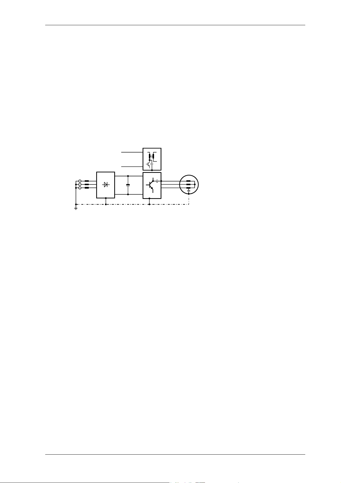
Interferences may be caused by:
y capacitive fault currents. This is caused by high voltage peaks and switching of bipolar transistors
and IGBTs.
4
2
1. Supply
2. Auxiliary voltage supply
1
+
3
5
3. Power stage
4. Switch mode power supply
5. Motor
y high currents and current peaks in the motor cables The interfering energy bound in magnetic fields
reaches frequencies of a few Hertz up to approx. 30 MHz. Due to the high voltage peaks, additional
electromagnetic fields occur with frequencies of up to approx. 600 MHz.
y high chopping rates and fast logic circuits (electromagnetic field / 16 MHz .. 1 GHz).
y Mains feedbacks and harmonics. These are caused by commutations and non-sinusoidal mains
loading, particularly for mains-commutated controllers (100 Hz ... 20kHz).
German EMC Law (EMVG)
This converter corresponds to EMVG §5 Section 5, Sentence 3 of EMVG (German EMC Law) dated 09
Nov.92.
"Devices, which are exclusively manufactured or stocked as vendor parts or spare parts for further
processing by industrial companies or craftsmen or by other specialists in the field of electromagnetic
compatibility do not need to comply with the protective requirements of Paragraph 4, Section 1, nor do
they need EU conformity certification and marking, assuming that the devices in question cannot be run
on their own.””
This takes into account that EMC is essentially dependent on the subassemblies of the individual
modules and components in the switch cabinet. Regarding the total costs of the machine, it is preferable
to suppress interference of an entire system rather than each of its individual components.
The information on the next pages is intended to allow the user to configure his plant according to the
latest knowledge in the field of EMC and to comply with legal regulations.
Mono Power Unit BUM 62 T 25
Baumüller Nürnberg GmbH 5.99009.03
Page 26
Installation
Measures for ensuring EMC
To ensure EMC you must observe the configuration information below.
Cabling
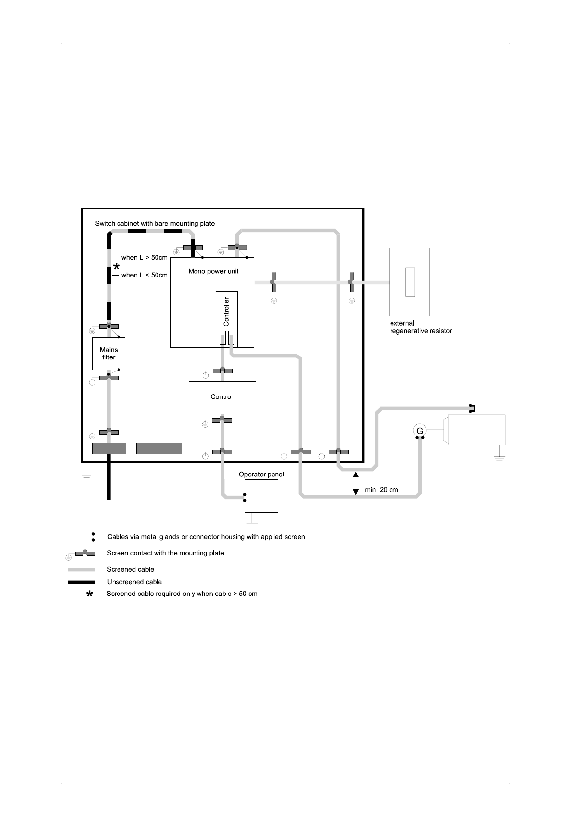
y To suppress noise emission outside the converter always screen all connected cables.
Also observe the items in Chapter ”Screening”.
26 Mono Power Unit BUM 62 T
5.99009.03 Baumüller Nürnberg GmbH
Page 27
Installation
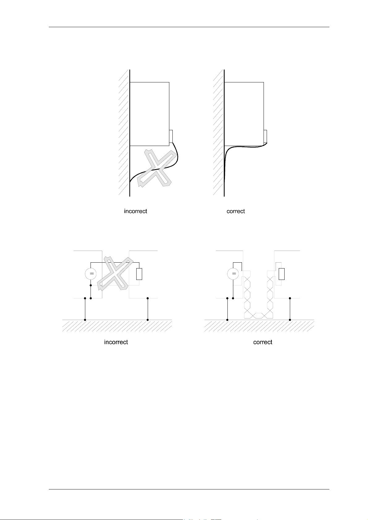
y You achieve the smallest possible effective antenna height by laying the cable directly on the ground
of the metallic rack.
y You should lay all cables as close as possible to the conductors of the ground system to reduce the
effective loop area for magnetic coupling.
y When laying signal and control cables in parallel across power cables, maintain a minimum distance
of 20 cm between the conductors.
y Cables of different EMC categories should only cross at an angle of 90°.
y For symmetrical signal transmission (e.g. differential amplifier inputs for the speed setpoint), twist
the conductors of each pair together and twist the pairs of wires together.
y The connection between converter and ground plate should be as short as possible (<50 cm). Use
large cross-sections (>10 mm
2
)
y Sources of noise such as fuses, transformers, chokes and noise-sensitive modules such as
microprocessors, bus systems, etc. should be located at least 20 cm away from the converter and
its cabling.
y Avoid reserve loops on long cables.
y The grounding of reserve wires in cables is mandatory (additional screening, avoidance of
capacitively coupled, hazardous contact voltages).
Mono Power Unit BUM 62 T 27
Baumüller Nürnberg GmbH 5.99009.03
Page 28

Installation
Grounding
y To meet EMC requirements, the classical star grounding is no longer sufficient to reduce the noise
of high frequencies caused by converter operation. Better results can be achieved by a reference
surface which must be linked to the units’ ground (e.g. bare metal mounting plate and housing parts).
y If a large reference surface is not possible the main equipotential bonding strip should be arranged
directly at the power unit which generates the largest potential steps compared to the other
components in the switch cabinet (ground connection < 50 cm if possible).
y To avoid earth loops, apply all ground connectors and screens as close as possible above the
ground.
y If it is possible to ground the controller reference potential of the power unit, make the connection
with as large a cross-section as possible and a short cable (<50 cm).
y Remove insulating layers such as paint, adhesives, etc. from the ground connections. If necessary,
use serrated lock washers (DIN 6798) or similar measures to ensure a permanent, conductive
contact. To prevent corrosion on ground connections, use suitable metal combinations
(electrochemical series of metals) and keep conductive electrolytes away from the connection by a
protective coating (e.g. grease).
y Always connect screens at both ends over a large surface and conductive to ground. This is the only
way to suppress the effects of magnetic or high-frequent noise. If earth loops occur (e.g. double
insulation of the setpoint conductor screen), apply the receiver side galvanically and the transmitter
side capacitively.
y When laying external cable screens through panels separating different EMC areas, make contact
to the cable screens.
Cables which are passed through the panels of screening housings without special measures (e.g.
filtering), may impair the screening effect of these housings. For this reason, you must make a
conductive connection of the cable screens at the point at which the cable enters the housing.
The distance of the last screen contact point to the exit of the cabinet must be as short as possible.
28 Mono Power Unit BUM 62 T
5.99009.03 Baumüller Nürnberg GmbH
Page 29
Installation
Screening
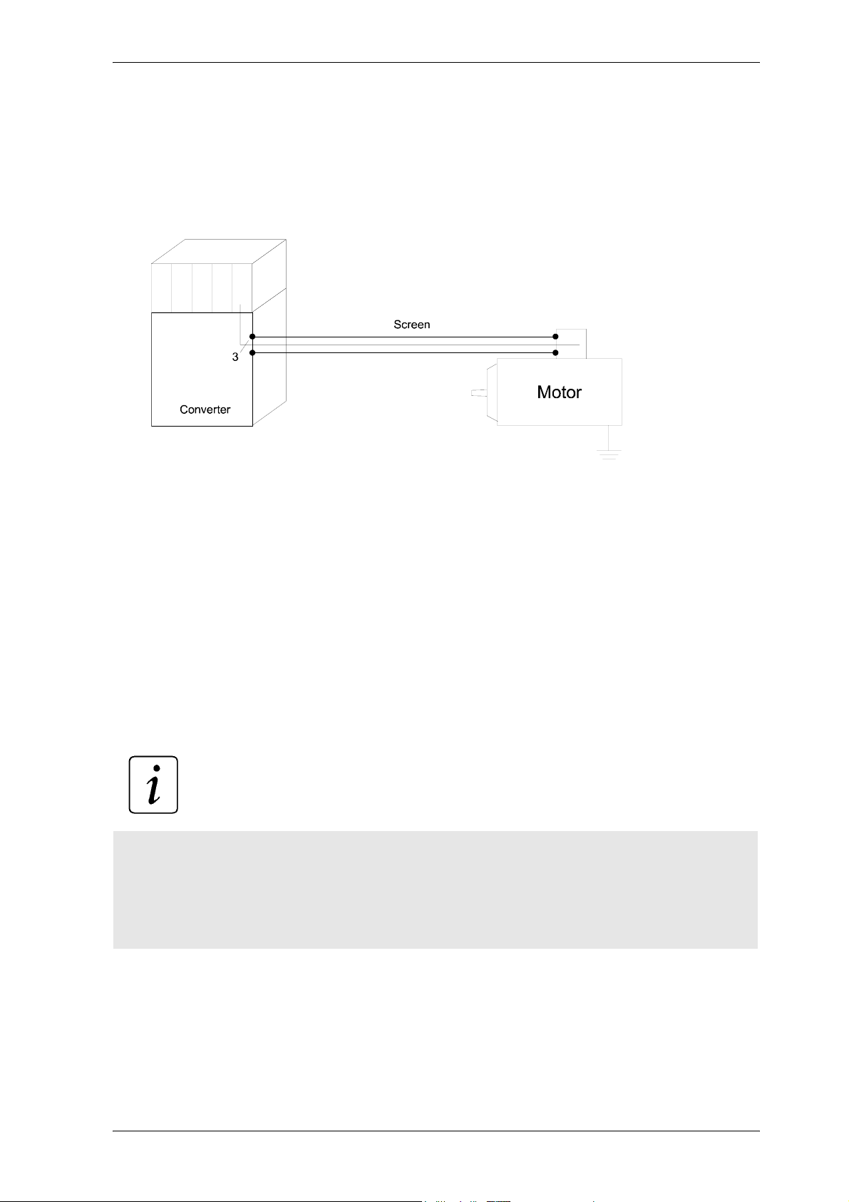
y The screen is effective against magnetic fields when it is connected to ground at both ends.
With electrical fields, the screening is effective if the screen is connected to ground at one end.
For electrical or magnetic fields with high frequencies (depending on the cable length), always apply
the screen at both ends because of the linkage (electromagnetic field).
If you apply the screen to ground at both ends, the cable does not leave the screening ”system
housing”.
y If you connect cable screens to ground at both ends, the effect of earth loops (potential difference
on the ground system) cannot be excluded totally. However, these are very rare if you observe the
measures of the above chapters ”Cabling” and ”Grounding”.
The HF connection of a screen to ground can also be capacitive. This prevents low-frequent noise
caused by earth loops.
Screen cables passing through different EMC areas must not be separated at the terminals,
otherwise the screening would be reduced considerably. They should be led to the next module
without interruption.
The screen connection should be of low impedance and over a large surface. Cable tails with a
length of only 3 cm (1 cm wire = 10 nH) reduce the screening of up to 30 dB when noise occur in the
MHz range!
NOTE
The screen braid must have a coverage of at least 85%.
The following cables have a particularly high interference potential:
– Motor cable
– Cable to external regenerative resistors
– Cable between mains filter and converter
Mono Power Unit BUM 62 T 29
Baumüller Nürnberg GmbH 5.99009.03
Page 30
Installation
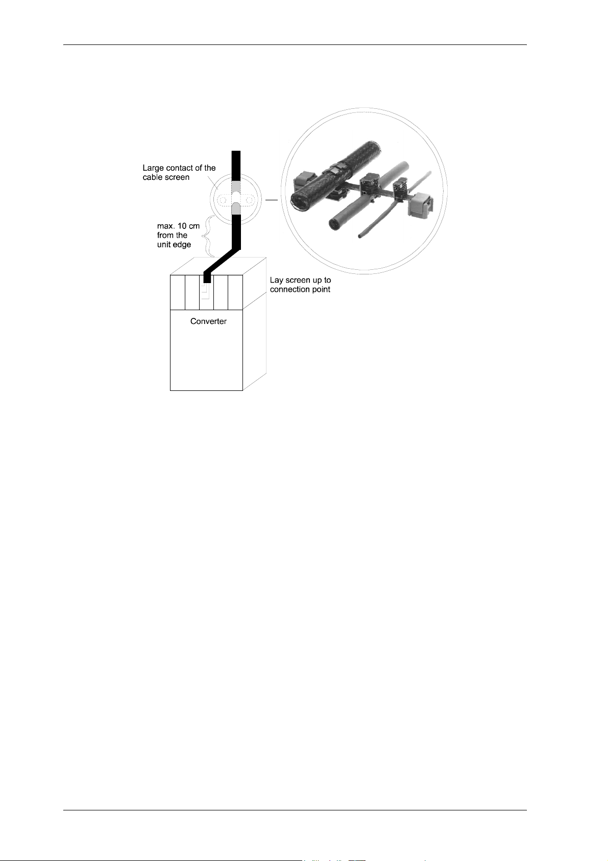
y Proposal for the screen connection
Filtering
No filters are necessary for the function of the converter. To maintain EMC regulations, filters at the input
or output side may be required.
If you have any queries about the filter dimensioning, please ask for the description ”Baumüller Filters
for Mains Applications BFN”.
Filter assembly
y Mount the filter next to the converter. If the cables are longer than 50 cm, screen the mains cable
between converter and filter (grounding at both ends).
y Input and output cables of the filter must be separated physically (distance > 50 cm).
y Connect the filter housing to ground over a large surface.
Leakage currents
Due to the principle of operation, stray capacitances in the filter, power stage, motor cable and motor
winding cause leakage currents of 100 mA and higher.
This means that converters with current-operated e.l.c.b. can be incompatible!
Observe the safety information in EN 50178:1994 Section 5.2.11.2.
30 Mono Power Unit BUM 62 T
5.99009.03 Baumüller Nürnberg GmbH
Page 31

Installation
6.3 Applicable standards
The power units of the series BUM 62 T are built-in devices according to EN 50178 / VDE 0160 / 11.94,
Section 5.2.6 and DIN VDE 0558 Part 1/07.87, Section 5.4.3.2.1.
Sheets of plastic covering the power connections, additionally prevent accidental contact during
commissioning and casual use of control elements located close to the equipment (DIN VDE 0106 part
100, Accident Prevention Regulation VBG4 "Electrical Systems and Equipment).
If the units are to be installed in closed electrical premises according to EN 50178/VDE 0160/11.94,
Section 5.2.7 and DIN VDE 0558 Part 1/07.87, Section 5.4.3.2.2, the user must ensure by additional
measures that the requirements according to EN 50178/VDE 0160/11.94, Section 5.2.4 are met.
Mains connection
The power unit is provided for the fixed mains connection to TN and TT mains according to DIN VDE
0100, Part 410/11.83 with a linked mains voltage of up to 3 x 460 V + 15%.
The power unit can be connected to IT mains using an isolating transformer with the neutral grounded
at the secondary side.
During operation, the principles on which the converter and motor work, lead to leakage currents to earth
which are dissipated via specified protective earth connections and which may result in a currentoperated e.l.c.b. on the input side blowing prematurely. A DC component in the fault current may occur
in the event of a short-circuit to frame or earth fault which makes a triggering of the higher-level currentoperated e.l.c.b. more difficult or even impossible. Universal-current sensitive current-operated e.l.c.b.
and current-operated e.l.c.b. for AC and pulsating AC fault currents with a rated fault current of 300 mA
are suitable.
The connection of the converter to the mains using only the current-operated e.l.c.b. is
prohibited (preliminary standard EN 50178 / VDE 0160 /11.94, sections 5.2.11 and 5.3.2.1)
Climatic conditions / Temperature
Concerning climatic conditions, the units of the climatic category 3K3 for sheltered locations acc. to EN
50178/VDE 0160/11.94, Section 6.1, Table 7, Line 3 or acc. to Table 1 of
EN 60721-3-1,2,3,4 under consideration of Note 1 and 3 of EN 50178/ VDE 0160/11.94, Section 6.1.
The actual operating temperature range is between 0 to +55 °C. For storage and transport, the
specifications of Table 7 (lines 5 and 6) of EN 50178/VDE 0160/11.94, Section 6.1 apply.
Unlike these specifications, the storage and transport temperature of the units may adopt values
between -30 and +70 °C (see technical data).
Type of protection
The type of protection of the units is IP 20 acc. to EN 60529 (DIN VDE 0470-1).
The power units are equipment of protection class I according to IEC 536/3 and DIN VDE 0106 Part 1
(EN 50178/VDE 0160/11.94, Section 5.2.9).
Mono Power Unit BUM 62 T 31
Baumüller Nürnberg GmbH 5.99009.03
Page 32

Installation
Equipment of protection class I is equipment, in which the protection against shock currents does not
only consist of the basic insulation and which includes an additional safety measure. This additional
protection is ensured by the connection and other parts to the PE so that no voltage is applied if the basic
insulation should fail. The entire insulation of these inverters acc. to EN 50178 / VDE 0160/11.94,
Section 5.2.9.1 complies at least to a basic insulation. This also applies to the insulation between the
individual circuits.
y The control connections of the power units are safely separated from the mains and are designed
for the connection of PELV/SELV circuits.
y The following criteria were considered for the dimensioning of the air and creepage distances:
Pollution degree 2 acc. to EN 50178/VDE0160/11.94, Section 5.2.15.2, Table 2, line 3
y Normally, only non-conductive pollution occurs. If the units are not in operation, a casual, short-term
conductivity caused by condensation is possible.
y Overvoltage category III acc. to IEC 664-1, Table 1 for air distances of mains circuits to their
environments acc. to EN 50178/VDE0160/11.94, Section 5.2.16.1.
y Voltage range of the mains circuit for TN and TT mains acc. to DIN VDE 0100 Part 410 / 1996 with
a phase-to-earth voltage ≤500 V.
y Insulating material IIIa for creepage distances acc. to EN 50178/VDE0160,/11.94, Section 5.2.17.
32 Mono Power Unit BUM 62 T
5.99009.03 Baumüller Nürnberg GmbH
Page 33

Installation
6.4 Safety relay
In this chapter we describe the safety relay.
6.4.1 Methods to avoid an unexpected starting
In order to avoid hazards against persons, for example operators, service- and maintenance technics,
the machine has to be kept in a secure condition (safe stop), while interfering in the hazardous area of
the machine. That is why a reliable prevention of an unexpected starting is demanded (amongst other
things Machine directive 89/392/EWG, appendix I, 1.6.3, last passage; EN 292-2, 4.1.4; EN 60204-1,
5.4). Under unexpected starting is to be understood every starting that can cause a risk when appearing
unexpected for persons (EN 292-1). Moreover, besides the transition of the release- to the operating
condition of the machine also the unexpected ramp-up of the machine, this means the transition from
the safe stop into an unsafe moving has to be considered. This is necessary, because the unexpected
ramp-up usually is to be led back to an interruption of the control loop of the machine. In this case the
drive is, because of its control system, anxious to achieve highest speed at maximal acceleration. If an
unexpected starting occurs, the operator therefore doesn’t have the possibility anymore to remove him
self or his hand from the hazard area. This is why the drive has to be stopped and has to be kept safe
in its ’off-position’, when having opened, electrical interlocked safety devices. The motor may not have
torque and thus cannot generate a dangerous movement.
The prevention of an unexpected starting of the machine can be reached by electrical separated safety
devices, e.g. contactors. By some machine types it has to be done without the isolation of the electrical
connection of the drive to the mains, if e. g. a drive supplied by a power converter is often stopped and
started again. The constant dis- and re-charging of the DC-link represents a big stress for the concerned
parts and often leads to disturbing delays and failures of these parts.
-
The requirement for the starting of a three-phase a. c. motor is the generation of a rotating field, which
drives the inductor of the motor. When having variable-speed three-phase current drives, usually in the
micro-processors a complex pulse pattern is generated, then the pulses are amplified and are used for
the switching of the power semiconductors. If either no defined pulse pattern is available or the amplify
ing connection is interrupted, e. g. by switching off of the power supply with a relay (safety relay), no
rotary field can be generated. An error by the pulse pattern generation therefore cannot lead to a starting
of the motor, as long as the second condition, namely the interruption of the amplifying power supply is
available and contrary. The protection against unexpected starting is reached by an electromechanical
method which is superior to the electronics. It is reached by a safe isolation - elsewhere than in the load
circuit.
The power supply to the windings of the motor is reached at a stoppage by inhibiting the power semiconductor. As semiconductors possibly can fail or be started, because of electromagnetic disturbances,
the behavior of the shut down drive has to be considered if such a fault scenario arises. The fail or "ac
cidental" turning on of a single or of more power semiconductors at the same DC-link pole does not lead
to an uncontrolled starting, as no current flow is accomplished. Not until additionally a further power
semiconductor is enabled at another DC-link pole, current is able to flow through the motor. If, thereby
the DC-link is directly short-circuited, the fuses which are upstreamed to the converter are tripped, the
motor doesn’t start. If the DC-link is "short-circuited" over a winding of the motor, a magnetic field can be
set up in the motor. If it is an asynchronous motor, then the generated d. c. magnetic properties cannot
cause a lurch of the inductor. By the permanent-magnetic synchronous motor the inductor will rotate into
a notch position. The therewith angular movement which is covered is dependable of the inductor’s po
sition and the number of pole pairs of the motor. It amounts to maximal 180°/number of pole pairs. Subsequently the enabled DC-link operates like a brake, this means after the ending of the lurching
movement the drive is in a blocked condition. A starting of the drive is impossible. If a machine with a
synchronous motor is planned, the possible sudden movement must be considered, because it can lead
to a dangerous movement. Therefore the machinist must carry out a safety evaluation for the residual
movement.
-
-
-
Mono Power Unit BUM 62 T 33
Baumüller Nürnberg GmbH 5.99009.03
Page 34
Installation
The function of the safety relay is limited to the prevention of an unexpected starting. The switching of
the safety relay, while the inductor of the motor is rotating, causes an uncontrolled "coasting" of the ma
chine, a braking with help of the converter is not possible anymore.
WARNING
Both on the motor and at the unit there can be mains voltage although safety relay is switched off.
If required, switch the appliance off-circuit like an appliance without a safety relay - the safety relay
does not switch the appliance and the motor off- circuit!
Turning off the safety relay has no isolation from the supply system as a consequence. Therefore, mains
potential can be both at the converter and at the motor. The protection against electric hazards has to
be therefore saved with other means (for example master switches) when maintaining, servicing or re
pairing electrical components of the drive system.
-
-
6.4.2 Safety categories
Dependant of the possible hazards (these are rated due to the consideration of the severity of the injuries, the frequency of the length of stay within the hazard area and possibilities in order to prevent hazards) security relevant components of machines have to meet certain safety criteria. The requirements
to safety-based parts are divided into five categories in the standard EN 954-1.
In category B basic demands, in 1 additionally safety-technical proved components and principles are
claimed. In category 2 an error between inspection intervals can lead to a loss of the safety function.
Category 3 accords to the level “the single-error-certainty to recognize errors partially”. The safety-relevant components must be in such a way, that a single error doesn’t lead to a loss of the safety function,
whereat not the complete possible errors can be self-contained recognized by the system. Therefore an
accumulation of unrecognized errors can lead to a loss of the safety function.
Category 4 accords to the level “Self-monitoring”. This component recognizes self-contained possible
errors and signals these in time of the loss of the safety function. Also if up to three from one another
independent errors arise the safety function is always maintained.
6.4.3 The safety relay
The function of the safety relay is executed in fail-safe-technic, also named closed-circuit principle. The
safety function “safe stop” is active, as long as no voltage is applied to the input terminals (X68: 3,4).
Consequently the functioning of the safety function is guaranteed if power failure takes place. In order
to deactivate “safe stop” a voltage of 24 V has to be applied to the terminals, which are intended for this
use (X68: 3,4).
For the external error monitoring of the safety relay´, the instantaneous control state can be interrogated
at its positively driven status signal contact (X68: 1,2). In case there is no voltage applied to the safety
relay (X68: 3,4), that means during the “safe stop”, then the status signal contact is closed (NC contact).
Also a parting of a cable can thusly be recognized as an error.
If the voltage at the input terminals of the relay (X68: 3,4) is switched off, then the converter generates
one or two error messages (F0204 and/or F0206), which it displays on the V-controller. The drive can
only be taken in operation again, if these messages are deleted after a reset of the safety relay with a
reset signal from the controller (for example by X26, pin programmable or over the interface to a bus
system).
34 Mono Power Unit BUM 62 T
5.99009.03 Baumüller Nürnberg GmbH
Page 35
Installation
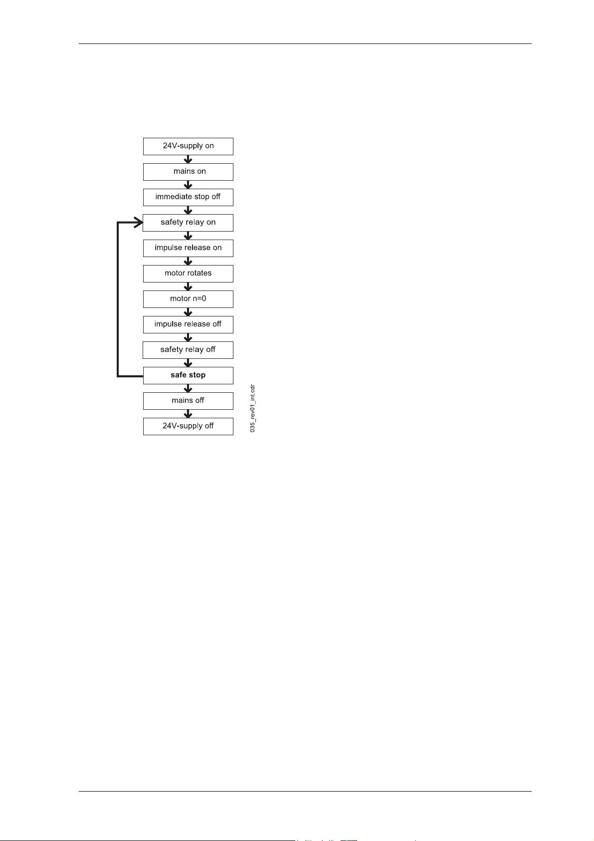
The closing- and opening sequence of the release signals as well as of the safety relay must be considered in order to assure a faultless operation of the drive.
Sequence diagram of the safety relay
Baumüller-devices of the series BUM 6, BUS 6 and BKH, which are made with one safety relay (optional), comply with the requirements of the category 3 (EN 954-1) for the safety-relevant using “protection
against unexpected starting”, if the configuring and installation instructions are complied with.
Before the commissioning of the machine, in which the converter with the safety relay is built in, the safety function “protection against unexpected starting” must be checked. For that purpose a safety device
must be executed (for example door contact). The motor must now be zero-torque.
If the reliability performance of the “protection of unexpected starting” once has been determined, then
this safety function of the converter doesn’t have to be checked by an external monitoring, as the device
checks itself on possible errors and if necessary displays a message as well as turns off the drive.
Mono Power Unit BUM 62 T 35
Baumüller Nürnberg GmbH 5.99009.03
Page 36
Installation
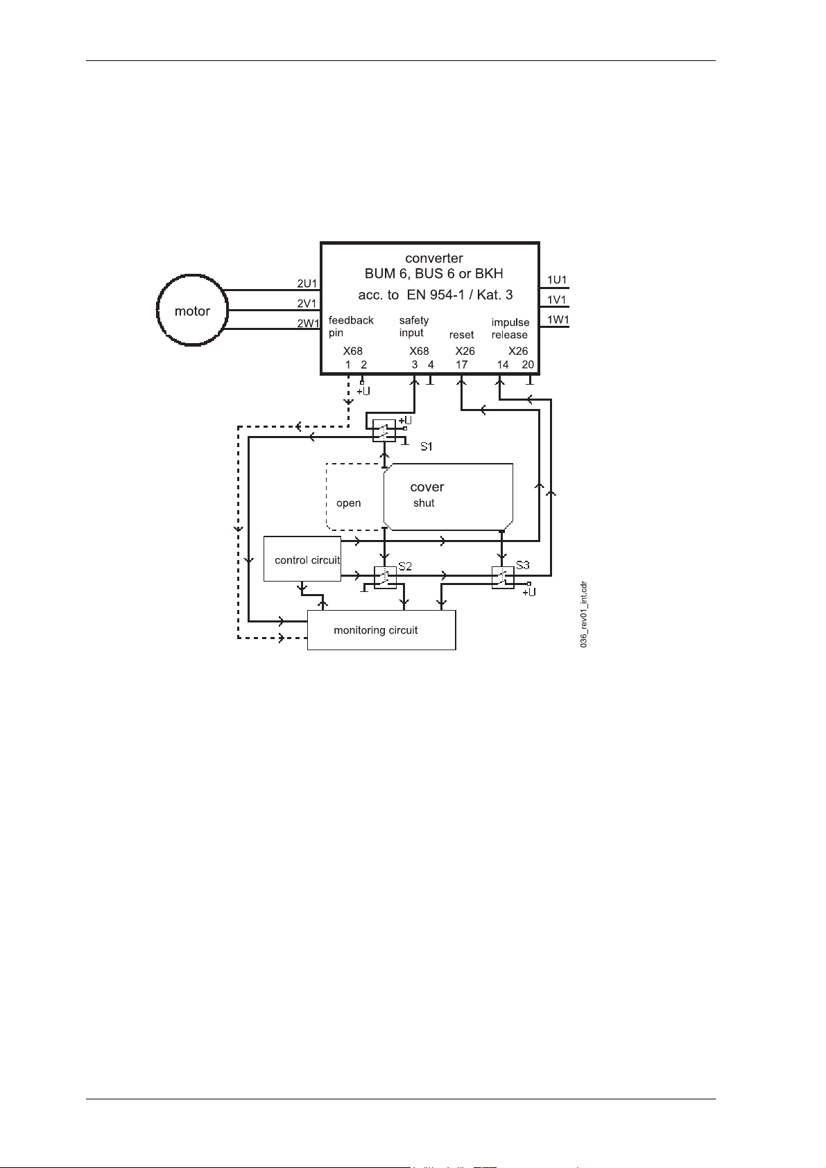
Application example for machine of category 3
Exemplary the following diagram shows the usage and cabling of a Baumüller converter of the series b
maXX in a machine tool, at which the safe taking of work pieces at opened barrier is possible according
to category 3 (EN 954-1).
Example for an application for safe stop according to category 3 (EN 954-1)
The switching-off of the electrical drive motor takes place dual-ported.
y S2 (NC contact) and S3 (NO contact) have hardware effects on the pulse release input of the con-
verter (X26: 14). Only if S2 and S3 display a closed cover (and therewith a safe condition) voltage is
being applied to the impulse release input of the converter.
y S1 (NC contact) has hardware effects on the safety relay of the converter. Only if S1 displays a
closed cover (and therewith a safe condition) voltage is applied to the safety relay input (X68: 3) and
therewith allows a torque generation at the shaft of the motor. The NO contact of S1 is connected
with the monitoring circuit.
y The monitoring circuit, a fail-safe monitoring control of the category 3 (EN 954-1), checks on its own
the directly connected switching contacts of the position switch S1 (NO contact), S2 (NO contact)
and S3 (NC contact). If the barrier is not completely closed or a theoretical impossible condition of
the position switch contacts is present (for example S1 and S2 show a different switching condition
or S2 and S3 show the same switching condition), then the control circuit will not get a release signal
from the monitoring circuit. A missing release signal of the monitoring device leads to a direct switch
ing off of the converter by means of the control circuit. If the monitoring circuit has recognized an
error (for example different switch condition of S1 and S2), this is displayed to the operator and a
commissioning of the drive is not possible until the error has been repaired.
y The status signal contact of the safety relay (X68: 1,2; NC contact) can additionally be evaluated by
the monitoring circuit (not obligatory).
-
36 Mono Power Unit BUM 62 T
5.99009.03 Baumüller Nürnberg GmbH
Page 37
Installation
y The position switches, which are used, must unavoidable have actuated and mechanical connected
contacts as well as a dual-port connection (NC contact/ NO contact). The mechanical operating at
the safety device must take place unavoidable, that means tamper-resistant.
The connection cables between the safety relay input (X68: 3,4) and the control as well as between the
impulse release input at the converter (X3:5) and the controller must not be installed outside the control
cabinet in a common cable channel.
Application example for machine of category 4
Additional procedures when configuring a machine make it possible with a converter of the category 3
(EN 954-1) at safety-relevant operations for the “protection against unexpected starting” also category
4 for the complete drive.
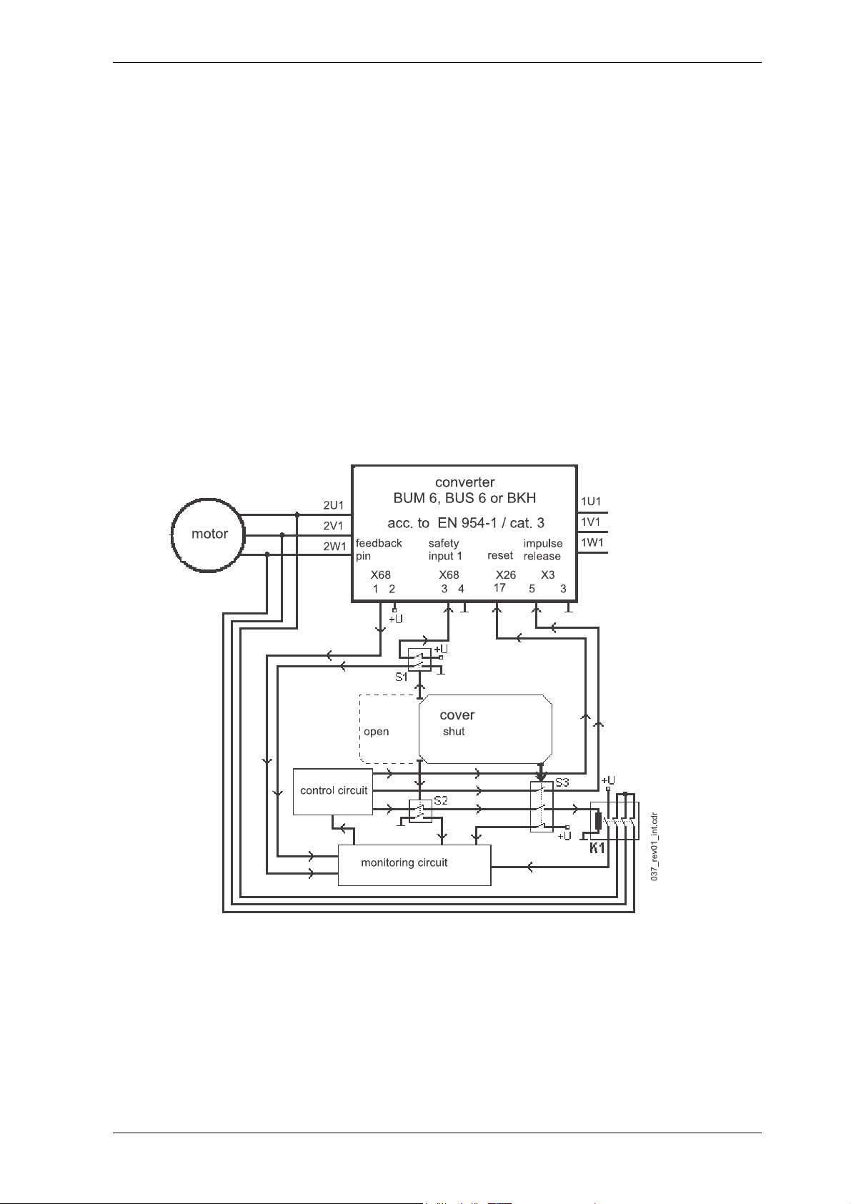
A possibility is the usage of a contactor, with which the external conductors of the motor cable is shortcircuited.
The diagram shows exemplary the usage and cabling of a Baumüller converter of the series BUM 6, BUS
6 or BKH of a machine tool, at which the safe taking of work pieces at opened barrier according to cat
egory 4 (EN 954-1) is possible.
-
Example for an application for safe stop according to category 4 (EN 954-1)
The switching-off of the electrical drive motor takes place three-ported.
y The contactor K1 with three NC contacts short-circuits the current to the motor in the release state
in all poles (closed-circuit current principle), so that no electrical energy of the converter arrives at
the motor. S2 (NC contact) and S3 (NO contact) effectuate K1. Only if S2 and S3 display a closed
barrier (and therewith a safe condition) K1 starts up and the short-circuit in the motor line is reset.
Mono Power Unit BUM 62 T 37
Baumüller Nürnberg GmbH 5.99009.03
Page 38
Installation
The status signal contact of K1 (NO contact) to the monitoring circuit is constructed with mechanical
with the NC contacts connected contacts. The selection of the contactor takes place after its limiting
short-time current load capability (10 ms). This must be bigger than the nominal current of the used
semiconductor fuses at the mains input of the converter.
y S1 (NC contact) has hardware effects on the safety relay of the converter. Only then if S1 displays
a closed barrier (and therewith a safe condition) voltage is applied to the safety relay input (X68: 3)
and therewith makes a torque generation at the shaft of the motor. The NO contact of S1 is connect
ed with the monitoring circuit.
y S3 (NO contact) has hardware effects on the impulse release input of the converter (X26: 14). Only
if S3 displays a closed barrier (and therewith a safe condition) voltage is applied to the impulse re
lease input of the converter.
y The monitoring circuit, a fail-safe monitoring control of the category 4 (EN 954-1), checks on its own
the directly connected switch contacts of the position switches S1 (NO contact), S2 (NO contact), S3
(NC contact) and the status signal contact of the safety relay (X68: 1,2; NC contact) as well as the
contactor K1 (NO contact). If the barrier is not completely closed or a theoretic impossible condition
of the position switch contacts is present (for example S1 and S2 show a different switch condition
or S2 and S3 show the same switch condition or the status signal contact of the safety relay is
opened/closed, although the status signal contact of S1 is closed/opened), the control circuit re
ceives no release signal of the monitoring signal. A missing release signal of the monitoring device
leads to a direct switching off of the converter by means of the control circuit. If the monitoring circuit
has recognized an error (for example different switch condition of S1 and S2), this if displayed to the
operator and the commissioning of the drive is not possible until the error has been repaired.
-
-
-
y The position switches, which are used, must unavoidable have actuated and mechanical connected
contacts as well as a dual-port connection (NC contact/ NO contact). The mechanical operating at
the safety device must take place unavoidable, that means tamper-resistant.
The connection cables between the contactor K1 and the control circuit as well as between the safety
relay input at the converter (X68: 3,4) and the control circuit must not be installed outside the switching
cabinet in a common cable channel.
NOTE
All information given in the Operation Manual of the converter, especially the chapters safety instruction, installation and commissioning, must absolutely be observed.
For the use and the installation of the safety devices the legal and official requirements of the government safety organizations and of the EU-Directives for safety requirements at installations and
machines (for example EN 60204-1, security of machines, electric equipment and EN 292-2 security
of machines general configuration directives) are valid.
6.4.4 Service time
The mechanical service time of the safety relay is at least 1 x 10⁷ cycles of operation.
38 Mono Power Unit BUM 62 T
5.99009.03 Baumüller Nürnberg GmbH
Page 39
6.5 Connection diagram
Installation
Mono Power Unit BUM 62 T 39
Baumüller Nürnberg GmbH 5.99009.03
Page 40
Installation
6.6 Terminal strips and plug-in terminals
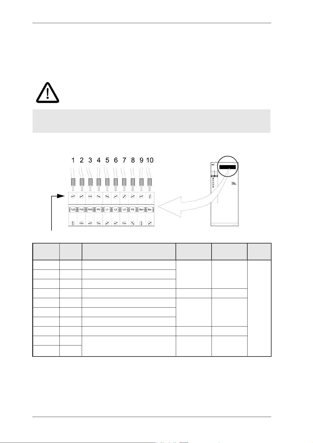
6.6.1 Power connections
DANGER
Danger to life!
The permissible connection value (see ”Technical data”) must never be exceeded.
Terminal strip X1
Screw connections for cable with wire crimp
Termina
Pos.
1)
Description
l
1U2 1 Motor connection phase U max. 570 V max. 130 A 10 - 25
1V2 2 Motor connection phase V
1W2 3 Motor connection phase W
PE 4 Earth connection
L1 5 Mains connection phase L1 400 V -15 %
L2 6 Mains connection phase L2
L3 7 Mains connection phase L3
PE 8 Earth connection
Ba+ 9 Connection regenerative resistor
Ba- 10
Ba+ is internally connected to ZK+, Ba- is
connected to the collector of the brake switch.
460V +10%
Ba+ and Ba-
max. 800 V
U
range
up to
between
2)
DC
3)
I
range
max. 105A
max. 73 A
4)
A
mm
8 - 4
AWG
2
1. Position
2. Voltage range (r.m.s. value)
3. Current range (r.m.s. value)
4. select the connection cross-section according to the applicable standards depending on the
application. The specified values indicate which flexible conductors are safely connected.
40 Mono Power Unit BUM 62 T
5.99009.03 Baumüller Nürnberg GmbH
Page 41
Installation
DC link terminals ZK+ and ZK- (adding units)
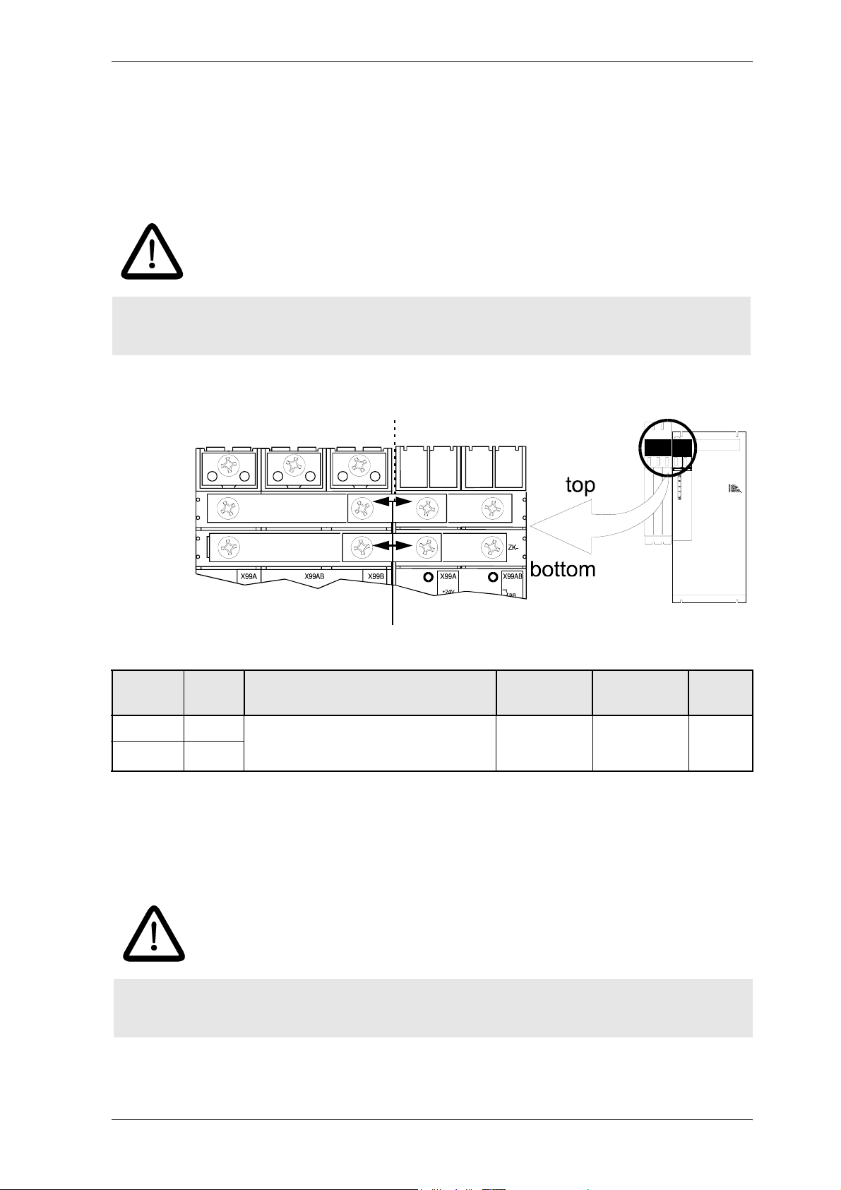
If a Baumüller unit is added to the BUM 62 T, connect the DC links of both units.
If you add power modules, the supply converter of the BUM 62 T supplies the connected power modules.
The individual modules exchange energy (e.g. during braking).
DANGER
The total power of the motors supplied via the power modules which are connected to the BUM 62 T
must not be higher than the power which can be supplied from the supply converter of the BUM 62 T.
.
Screw connections for bar connection M6
Termina
Pos.
1)
Description
l
ZK+ top DC link connection
ZK- bottom
Connection of two Baumüller units
ZK+ and ZK-
max. 800 V
U
range
between
2)
DC
3)
I
range
max. 65 A
A
16 mm
1. Position
2. Voltage range (r.m.s. value)
3. Current range (r.m.s. value)
4. Conducting cross-section of the bars
DANGER
Reassemble and tighten the supplied covers after having connected the DC links of the two units
using a bar.
4)
2
Mono Power Unit BUM 62 T 41
Baumüller Nürnberg GmbH 5.99009.03
Page 42

Installation
6.6.2 Control connections
WARNING
The permissible maximum current of 10 A per connection point must not be exceeded, otherwise the
units may be damaged.
All control voltages applied externally must comply with the regulations
for PELV or SELV
42 Mono Power Unit BUM 62 T
5.99009.03 Baumüller Nürnberg GmbH
Page 43
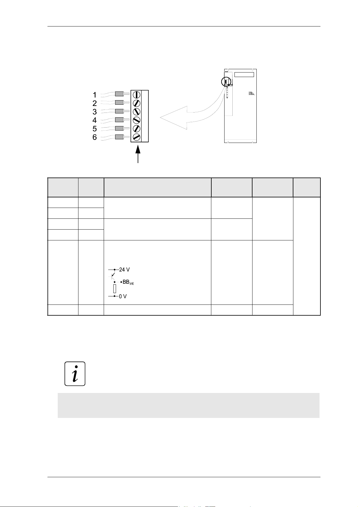
Plug-in terminal X99A
Installation
Screw connections for cable with wire crimp
Termina
Pos.
1)
Description
l
+24 V 1
+24 V 2
M 24 V 3 Ground 24 VDC (PELV)
M 24 V 4
BB
int.
ZUS. 6 Reserve - -
+ 24 VDC (PELV)
Terminals 1 and 2 are bridged internally
Terminals 1 and 2 are bridged internally
5
Message ”Internal ready for operation"
0 V Supply part is not ready
24 V Supply part is ready
5)
6)
24 V +20 %
24 V -10 %
(PLC level)
U
range
0 V
0 V
or
24 V
2)
3)
I
range
max. 10 A 0.2 -2.5
-
A
mm
24 - 12
AWG
1. Position from the top
2. Voltage range (r.m.s. value)
3. Current range (r.m.s. value)
4. Cross-section of the conductor. Observe EMC requirements (see EMC information on page 25)
5.
4)
2
NOTE
The input of the power supply includes capacitors (250 µF) so that charge current occur when the
24V supply is switched!
6. This message only refers to the BUM 62 T, and not to the controller!
(see also ”Ready for operation” on page 53 )
Mono Power Unit BUM 62 T 43
Baumüller Nürnberg GmbH 5.99009.03
Page 44
Installation
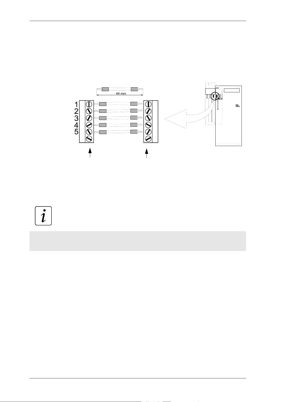
X99A (adding units)
If you add a Baumüller unit to the BUM 62 T, connect terminals 1 to 5 of relay X99B of the added unit to
terminals 1 to 5 of relay X99A of the BUM 62 T.
Connection
X99B X99A
(added unit) (BUM 62 T)
for instance BUR 622
NOTE
The combination of two plug-in terminals and connecting cables (see figure above) is available as an
accessory from Baumüller Nürnberg.
44 Mono Power Unit BUM 62 T
5.99009.03 Baumüller Nürnberg GmbH
Page 45
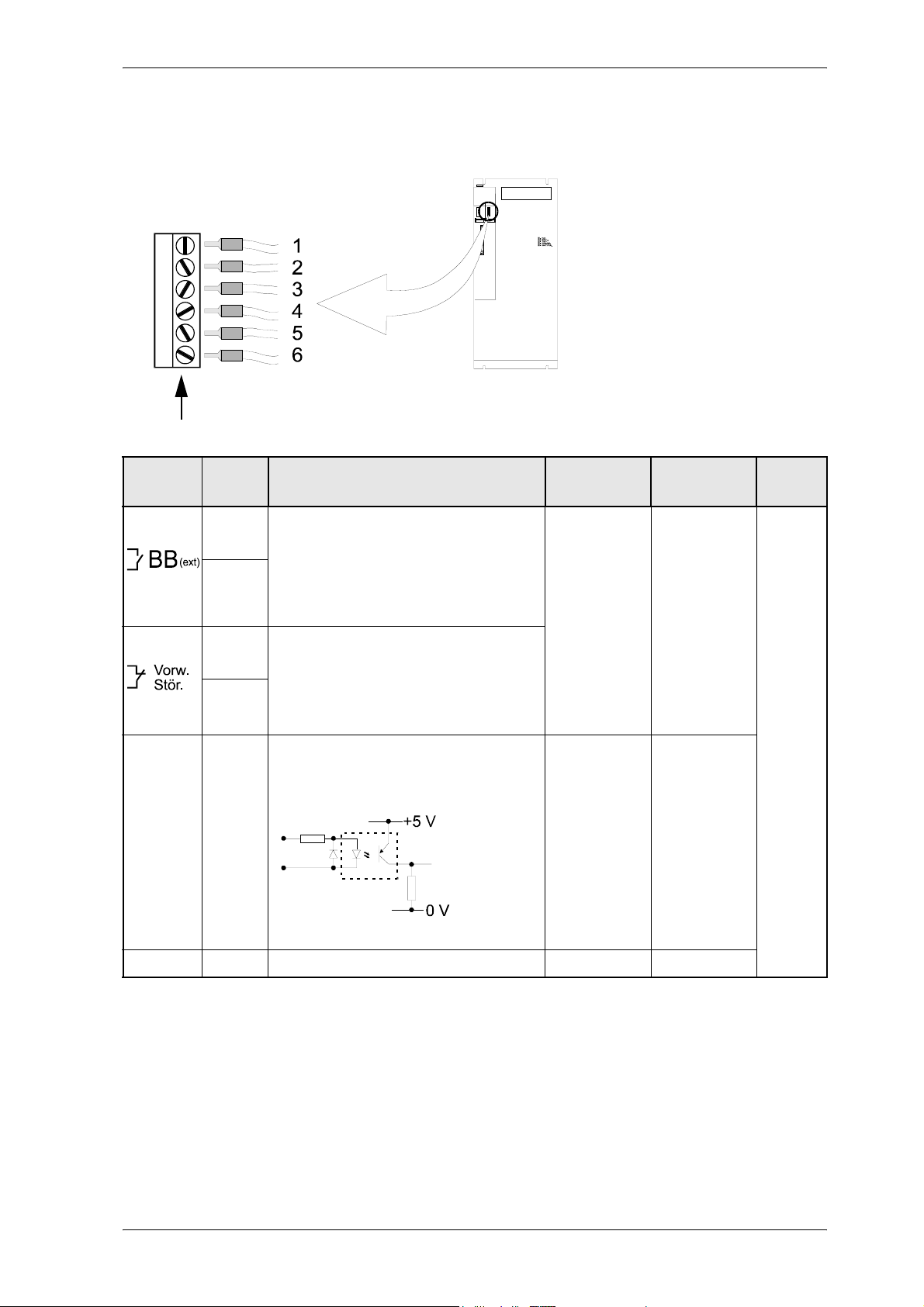
Plug-in terminal X99 AB
Screw connections for cable with wire crimp.
Installation
Termina
Pos.
1)
Description
l
Message "External ready for operation" 5)
Open contacts.
1
Supply part not ready
2
Closed contacts.
Supply part ready
Message "Early warning" 5)
Closed contacts.
3
Supply part – no early warning
4
Open contacts.
Supply part – early warning
+Reset 5 isolated optocoupler input to
reset error messages.
PHASE ERR, POWER ERR, and BRAKE
OVERL.
2)
U
range
24 V 0.5 A max.
24 V -
I
range
3)
4)
A
2.5 mm
2
M Reset 6 Reference to input +Reset 0 V -
1. Position
2. Voltage range (r.m.s. value)
3. Current range (r.m.s. value)
4. Cross-section of the conductor
5. This message only refers to the BUM 62 T, and not to the controller!
(see also ”Messages via relay contacts” on page 61 )
Mono Power Unit BUM 62 T 45
Baumüller Nürnberg GmbH 5.99009.03
Page 46
Installation
6.6.3 Controller connection
Plug-in terminal X60. Refer to the description of the controller.
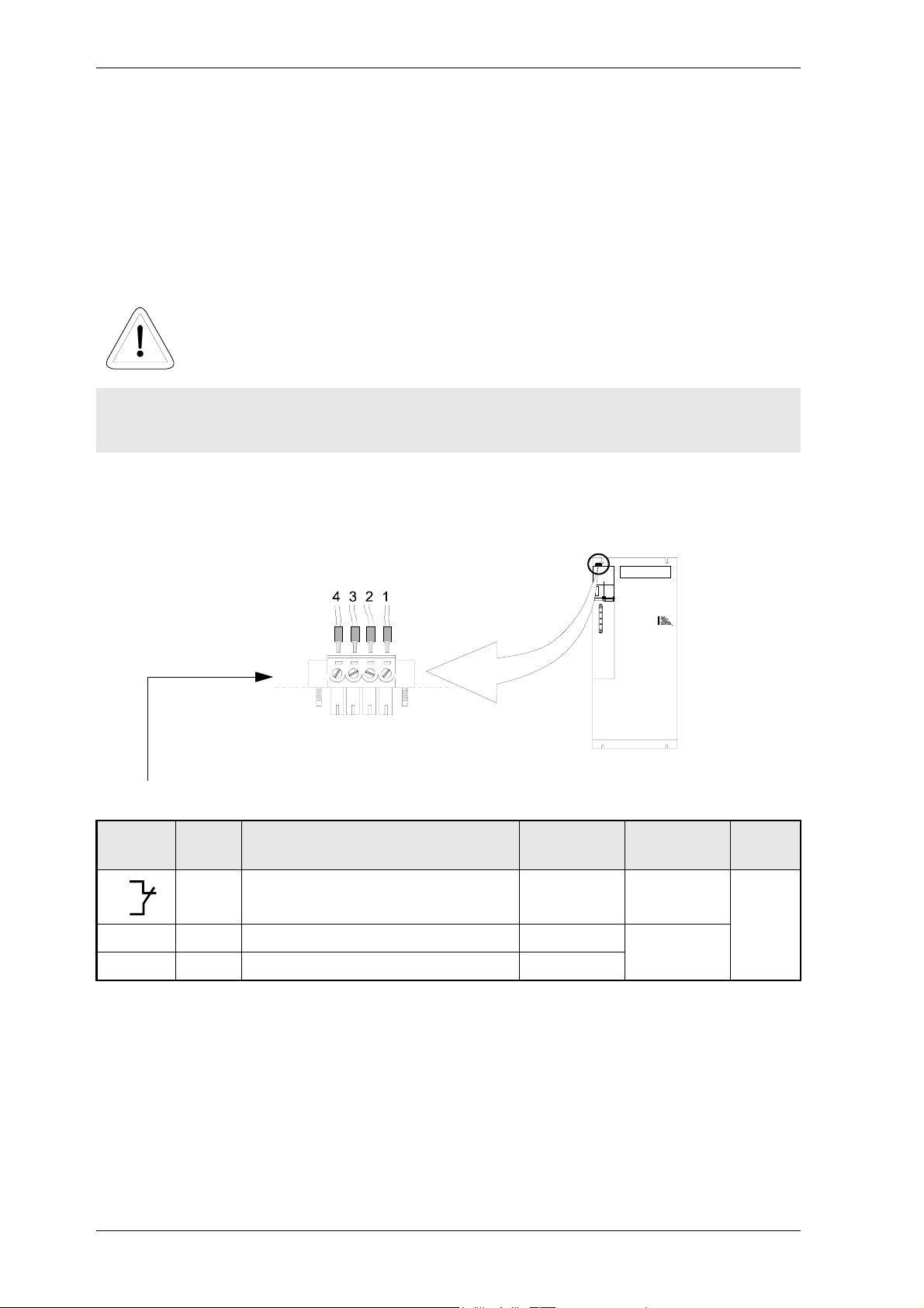
6.6.4 Safety relay (as an option)
The safety relay is used to disconnect load from the drive by switching of the +24V via contacts 3 and 4.
WARNING
The user must prevent overloading of the relay contacts, e.g. by suitable fuses.
The load of 10 mA is a minimum load to ensure permanently a trouble-free function.
Plug-in terminal X68
Screw connection, cable with wire crimp
Termina
Pos.
1)
Description
l
1
Feedback whether the safety relay
is supplied with 24 V
2
+24 V 3 + 24 V connection for the safety relay (PELV) +24 V max. 25 mA
M 24 V 4 Ground connection for the safety relay (PELV) 0 V
2)
U
range
+24 V max. 8 A
1. Position
2. Voltage range (r.m.s. value)
3. Current range (r.m.s. value)
4. Cross-section of the conductor
I
range
3)
4)
A
1.5 mm
2
46 Mono Power Unit BUM 62 T
5.99009.03 Baumüller Nürnberg GmbH
Page 47

NOTE
During motor operation, +24 V DC must be applied at the terminals 3 and 4.
Safety relay OFF is saved as a message and must be reset via the controller.
6.7 Accessories
y EMC package
– EMC filter
– Screened cables
– Connection parts
Installation
Mono Power Unit BUM 62 T 47
Baumüller Nürnberg GmbH 5.99009.03
Page 48

Installation
48 Mono Power Unit BUM 62 T
5.99009.03 Baumüller Nürnberg GmbH
Page 49
Commissioning
7 COMMISSIONING
7.1 Danger information
WARNING
This device carries dangerous voltage and contains dangerous rotating parts (fans). Ignoring the
safety and warning information may result in death, severe personal injury and/or damage to material
assets.
The user is responsible for the assembly of the converter, the motor, the mains choke and the other
devices according to the safety regulations (e.g. DIN, VDE) and all other relevant nations or local
regulations concerning the conductor ratings and protection, grounding, disconnectors, overcurrent
protection, etc.
The protective measures and safety regulations according to DIN/VDE are binding for personal
security. If there are no PE connections on the unit, the commutation choke or the motor, personal
injury may be caused since the surface may carry hazardous voltage.
The power connections of the converter carry potential!
The parts of the converter carry hazardous voltage even if the main contactor has released.
During operation, the principles on which the converter and motor work, lead to leakage currents to
earth which are dissipated via specified protective earth connections and which may result in a currentoperated e.l.c.b. on the input side blowing prematurely.
A DC component in the fault current may occur in the event of a short-circuit to frame or earth fault
which makes a triggering of the higher-level current-operated e.l.c.b. more difficult or even impossible.
Make the PE connection according to DIN EN 60204 / VDE 0113 Part 1 / 06.93, Section 8.2.2.
considering EN 50178 / VDE 0160/11.94, Sections 5.3.2.1 and 8.3.4.4.
Before commissioning check whether the plastic covers over the live parts (power part connections)
are in place.
Mono Power Unit BUM 62 T 49
Baumüller Nürnberg GmbH 5.99009.03
Page 50
Commissioning
WARNING
Malfunction of the drive
During the initial commissioning, a faulty or uncontrolled movement of the driven machine elements
cannot be excluded. Therefore, proceed with particular care.
Prior to connecting the drive, carefully check all higher-level safety equipment for perfect functioning,
to avoid personal injury.
Special care must be taken when touching the drive shaft directly or indirectly (by hand). This is
permissible only when the shaft is at standstill and the converter is de-energized. Machine parts which
are freely accessible during operation (shafts, fans, etc.) must be covered.
Protection against contact according to Paragraph 4 Section 4 VBG 4
Protection against direct contact comprises all measures against danger which can result from
touching the active parts of electrical equipment.
The active parts must therefore be protected from direct contact by insulation, design, position,
arrangement or firmly installed facilities. Protection refers to common covers, barriers and procedures
which ensure that persons are prevented from touching live, active parts.
Switch cabinet must have emergency stop facilities using which all voltages causing dangerous
situations, can be switched off. This does not include equipment which, if switched off, would cause
another dangerous situation. The releasing element for the emergency stop facility must be arranged
such that it can easily be reached in case of danger. In the event of work which is considerably more
dangerous that usual, another person must be present.
The operator must ensure that unauthorized persons do not work on the machine.
50 Mono Power Unit BUM 62 T
5.99009.03 Baumüller Nürnberg GmbH
Page 51
Commissioning
WARNING
Subsequent high-voltage tests must only be carried out by BAUMÜLLER NÜRNBERG GmbH. If you
want to carry out high-voltage tests for complete switch cabinet installations, disconnect all cables
from the devices prior to the test.
When an error occurs, the drive is de-energized and the motor coasts to stop. This fact must be taken
into account particularly for hoist and lifting drives.
The operator must report immediately any changes that occur which adversely affect the safety of the
unit/system.
When dismantling safety equipment during commissioning, repair and maintenance, ensure that the
machine is taken out of commission in accordance with applicable regulations. Remount and check
the safety equipment immediately after completing commissioning, repair and maintenance work.
This list does not claim to be complete for the safe operation of the unit. If you should need further
information or if special problems arise please contact BAUMÜLLER NÜRNBERG or a sales agency.
Please observe the warnings in Chapter 1 of these operating instructions.
NOTE
Prior to touching the modules, the user must discharge electrostatically to protect electronic
components from high voltages caused by electrostatic charge. This can simply be achieved by
touching a conductive, grounded part immediately before touching the electronic component.
Devices with electrostatically endangered components or modules are marked
using this label at a visible position.
Mono Power Unit BUM 62 T 51
Baumüller Nürnberg GmbH 5.99009.03
Page 52
Commissioning
7.2 Operation
The device is almost exclusively operated via the controller (see controller description).
Reset (acknowledgement) of errors via the optocoupler input ”Reset” of the connector strip X99AB is the
only exception from this.
7.3 Monitoring functions and their messages
NOTE
Monitoring functions are active only when the +24V supply voltage (X99A) is applied.
The monitoring functions of BUM 62 T is divided into two groups. The first group is ”Monitoring functions
of the supply part”. The second group is ”Monitoring functions of the power part on the motor side”. This
division corresponds to the internal design of the unit.
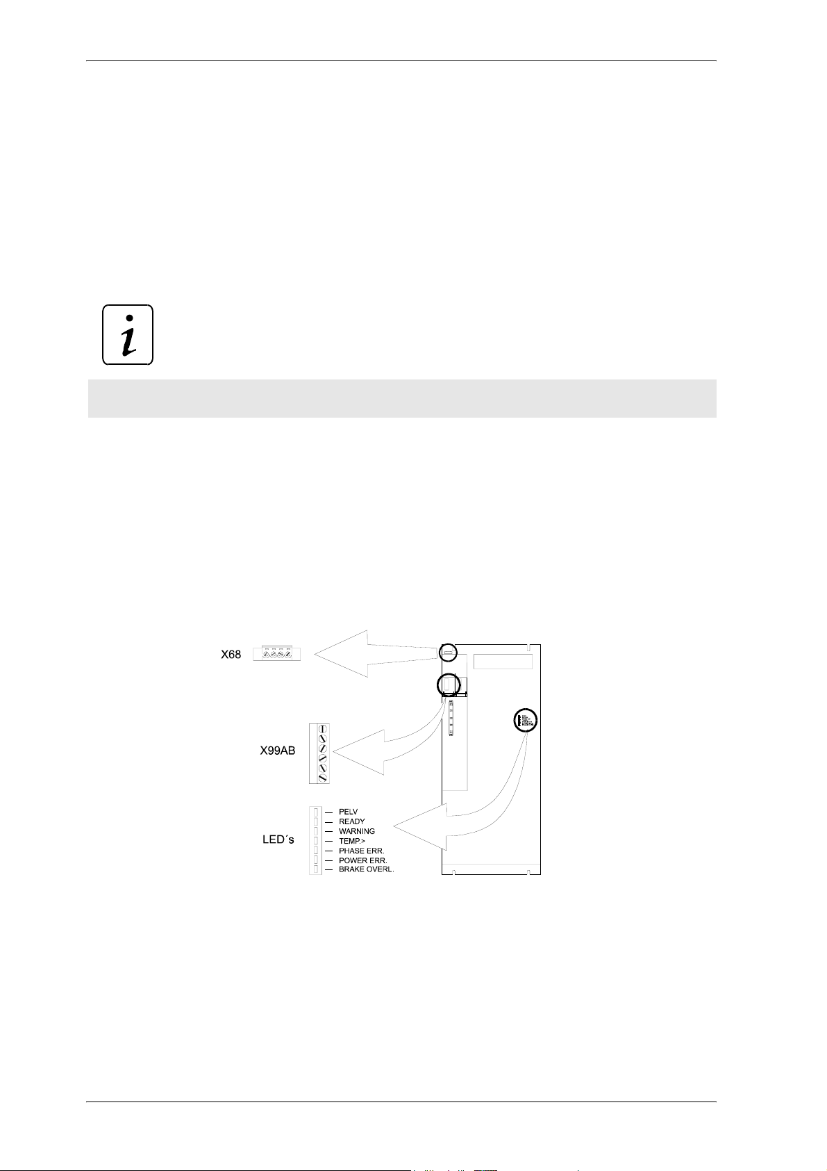
Monitoring functions of the supply part
The messages generated by the ”Monitoring functions of the supply part” are indicated via relay contacts
and/or displayed by LEDs. The messages are sent simultaneously to the controller which processes it.
The position of the relay contacts and the LEDs is illustrated on the following figure
For more detailed information on the messages and the LEDs/relay contacts refer to ”Messages via
LEDs” page 60 and to ”Messages via relay contacts” page 61.
Monitoring functions of the power part on the motor side
The messages generated by the ”Monitoring functions of the power part on the motor side” are
exclusively sent to the controller which processes them.
52 Mono Power Unit BUM 62 T
5.99009.03 Baumüller Nürnberg GmbH
Page 53
Commissioning
7.3.1 Ready for operation
The message ”Ready for operation” is the most important message for you. If a monitoring function
generates a message which clears the ”Ready for operation” message, the production of your plant is
stopped in the worst case.
There is more than one ”Ready for operation” message. If, e.g. a V controller is included in the BUM 62
T, four different ”Ready for operation” messages can be displayed in a drive.
y ”Supply part ready” (available and visible in the BUM 62 T)
= ”Internal ready for operation” (digital output)
= "External ready for operation"(relay contacts)
y ”Supply part ready” (available in the BUM 62 T and not visible)
y ”Controller ready” (available in the controller)
y ”Completely ready” (available in the controller)
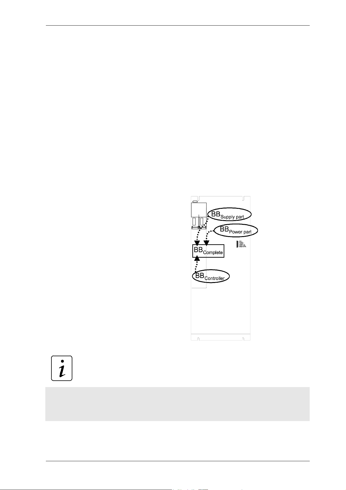
The message ”Completely ready” depends on the three other ”Ready” messages. The message
”Completely ready” is output only when the messages ”Supply part ready” and ”Power stage ready” and
”Controller ready” are output (see figure).
NOTE
The drive is ready approx. 3.5 seconds after the +24V supply voltage and the mains voltage have been
applied.
”Power part ready” after approx. 0.5 s. ”Controller ready” after approx. 3 s
The following sections provide further information on the different ”Ready” messages.
Mono Power Unit BUM 62 T 53
Baumüller Nürnberg GmbH 5.99009.03
Page 54

Commissioning
”Supply part ready”
When the ”Monitoring function of the supply part” does not recognize any errors, the monitoring function
generates the message ”Supply part ready”.
y If the message ”Supply part ready” is cleared by the monitoring function, the BUM 62 T
disconnects the load from the drive, i.e. the units does no longer supply a torque.
The BUM 62 T displays this message using an LED and supplies it to relay contacts at the same time.
For more information refer to
The ”Supply part ready” is also referred to as "Internal ready" (terminal designation BBint)
or "External ready" (terminal designation BBext).
Both messages are identical. The difference lies in the internal structure of the unit.
At the output of the supply part, ”Supply part ready” is also referred to as ”Internal ready”. After the
message of the unit has been passed on to the power part, the message ”Supply part ready” is referred
to as ”External ready”.
”Messages via LEDs” page 60 and ”Messages via relay contacts” page 61.
”Power part on the motor side ready”
When the ”Monitoring function of the power part on the motor side” does not recognize and errors, the
monitoring function generates the message ”Power part on the motor side ready”.
y If the message ”Power part on the motor side ready” is cleared by the monitoring function,
the BUM 62 T disconnects the load from the drive, i.e. the units does no longer supply a
torque.
”Controller ready”
The V controller was mentioned at the beginning of this section. It may be possible that you use another
controller. Therefore, we will not provide any further information and refer to the corresponding
documentation. The documentation of your controller provides information on whether the message
”Controller ready” is available in the controller you are using and how you can process this message, if
available.
”Completely ready”
The above mentioned information applies here as well. The documentation of your controller provides
information on whether the message ”Completely ready” is available in the controller you are using and
how you can process this message, if available.
54 Mono Power Unit BUM 62 T
5.99009.03 Baumüller Nürnberg GmbH
Page 55
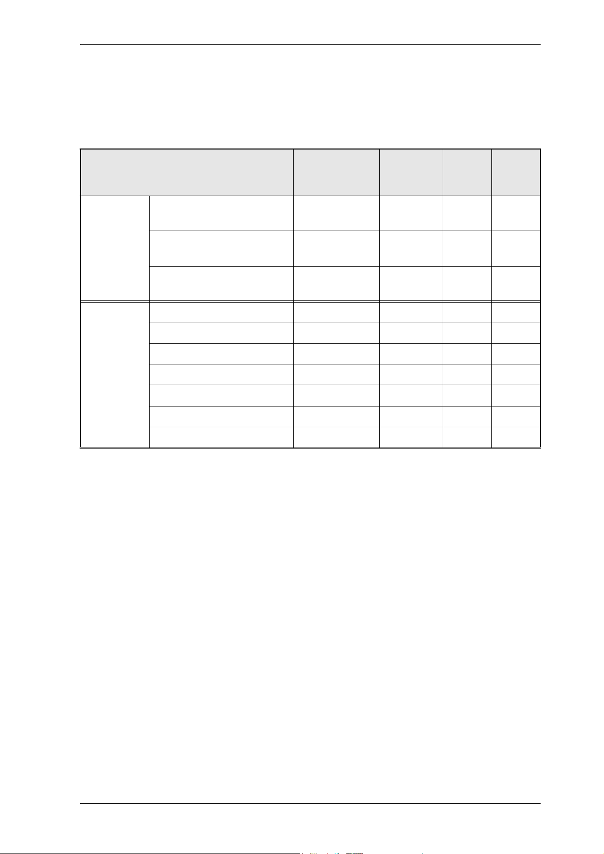
Commissioning
7.3.2 Monitoring functions
The following table lists all monitoring functions. An explanation of every individual monitoring function
will be given on the following pages.
Monitoring function LED Relay V-
controlle
r
Supply part Phase failure WARNING
PHASE ERR.
Mains failure WARNING
POWER ERR.
power part
on the
motor side
Short circuit regenerative
circuit output
Overcurrent (motor) - -
Earth current (short circuit) - -
Overvoltage DC link
Power transistors
Overheat heat sink
Internal auxiliary voltage
Safety relay
BRAKE OVERL.
- -
- -
- -
- -
-
X99AB; 3,4
X99AB; 3,4
-
X 68; 1,2
F 0110
F 0110
F 01101)U
F 0202 cont.
F 0203 cont.
F 0201 cont.
F 0207 cont.
F 0205 cont.
F 0204 cont.
5)
F 0206 cont.
1)
1)
Reset
24 V
24 V
3)
ZK
2)
2)
4)
4)
4)
4)
4)
4)
4)
1. The V controller always outputs this collective message in the event of an error in the supply part.
The corresponding LED displays on the front of the unit which error has occurred.
2. Trigger reset input (apply +24V and M24V at X99AB, optocoupler input).
or
Switch off +24V supply voltage.
This clears all messages of the supply part!
If you observe the WARNING message, you can bring the drive to a defined operating state before
the power unit clears the ”Supply part ready” message and de-energizes.
3. Not possible via the reset input! For safety reasons you have to wait until the DC link has discharged
(U
< 20 V), then switch off +24-V supply voltage.
ZK
This clears all messages of the supply part!
4. You must clear this message by a controller reset.
The controller documentation specifies how to display and clear the message.
5. A message occurs only if the safety relay is switched off. The safety relay is switched off only if the
+24V supply voltage for the relay is not applied.
Switch on again the +24 V supply voltage for the relay before you can clear the message by a
controller reset.
Mono Power Unit BUM 62 T 55
Baumüller Nürnberg GmbH 5.99009.03
Page 56
Commissioning
Reset
NOTE
Reset: If the message cannot be reset, it is very likely that the cause of the error has not yet been
removed.
Monitoring functions of the supply part
y Phase failure monitoring function
The voltage of all mains phases is monitored. If a mains phase fails, the BUM 62 T generates a
WARNING message. If the voltage returns within 10 seconds, the WARNING message is cleared.
If the mains phase fails for more than 10 seconds, the WARNING message is cleared and the
message ”Phase failure” is stored. The message ”Supply part ready” is cleared.
y Mains failure monitoring function
The voltage of all mains phases is monitored. Two different situations are possible:
1. Two or three mains phases fail and the DC link voltage slowly reduces.
y The WARNING message is set.
y The message ”Mains failure” is output, as soon as the DC link voltage is smaller than 300 V.
y The message ”Supply part ready” and the WARNING message are cleared.
2. Two or three mains phases fail and the DC link voltage reduces very fast
(within a few milliseconds).
y The message ”Mains failure” is output, as soon as the DC link voltage is smaller than 300 V.
y The message ”Supply part ready” is cleared.
y The WARNING message is set (for a few milliseconds).
Reason: If two or three mains phases fail, the procedure ”Output WARNING message” is started.
This procedure takes a few milliseconds. If the DC link voltage falls below 300 V within this time, the
message ”Supply part ready” is cleared immediately. The WARNING message is then set and
cleared immediately since the message ”Supply part ready” is no longer available.
NOTE
After the +24V supply voltage has been switched on, the output of the ”Mains failure” monitoring
function is stored only if:
y the mains is recognized to be "okay" and the DC link has fallen below 300 V.
To achieve an automatic restart e.g. after mains interrupt, you can avoid the storing of the messages
by a permanent triggering of the reset input (apply +24V and M24V at X99AB, optocoupler input),
56 Mono Power Unit BUM 62 T
5.99009.03 Baumüller Nürnberg GmbH
Page 57
Commissioning
provided that the mains failure time > 0 seconds has been set. Refer to ”Mains failure time” in the
controller description)
w
WARNING
If you enable an automatic start of the drive, you cause a severe danger of the operating personnel.
If a enable an automatic start of the drive, you must provide a protection on the machine side!
y Monitoring function of short-circuit regenerative circuit output
The connection for the external regenerative circuit is monitored.
If the monitoring function recognizes a short-circuit at the connection for the external regenerative
circuit, the message ”Short-circuit regenerative circuit” is generated. This message is stored and the
message ”Supply part ready” is cleared.
w
WARNING
A short-circuit of the regenerative circuit may destroy the unit.
Mono Power Unit BUM 62 T 57
Baumüller Nürnberg GmbH 5.99009.03
Page 58
Commissioning
Monitoring functions of the power part on the motor side
y Overcurrent (motor) monitoring function
Each of the three motor phase currents is monitored.
If the phase current exceeds 30% of the peak value of the permissible peak current, the BUM 62 T
generates a message. This message is stored in the BUM 62 T and transmitted to the controller. The
message ”Power stage on the motor side ready” is cleared.
NOTE
The overcurrent message and the subsequent stop of the drive protects the drive from damage/
destruction. To avoid the message Overcurrent (motor), you must limit the permissible peak
current of the motor phase currents by the control.
y Earth current (short-circuit) monitoring function
The earth fault current of the motor phases is monitored.
A message is generated when the fault current exceeds 20 % of the peak value of the permissible
peak current of the power part. An earth fault at the motor connection is very probable. This message
is transmitted to the controller. The message ”Power part on the motor side ready” is cleared.
y Overvoltage DC link monitoring function
The voltage of the DC link is monitored.
If the DC link voltage exceeds 800 V, a message is generated. This message is transmitted to the
controller. The message ”Power stage on the motor side ready” is cleared.
NOTE
The DC link voltage can rise until it is switched off if the drive brakes and no or an insufficient
regenerative circuit is connected to the DC link.
y Power transistors monitoring function
The collector-emitter saturation voltage is monitored.
If the voltage is too high, an overcurrent is applied to the power transistor, caused e.g. by a shortcircuit of the motor terminals and a controlled switch-off procedure switches off the transistor and
generates a message. This message is transmitted to the controller. The message ”Power stage on
the motor side ready” is cleared.
NOTE
To ensure a recovery of the transistor after a switch-off because of overcurrent, the message can
only be reset after at least 5 seconds (typically 10 s).
58 Mono Power Unit BUM 62 T
5.99009.03 Baumüller Nürnberg GmbH
Page 59

Commissioning
y Overheat heat sink monitoring function
The temperature of the heat sink is monitored.
A linear thermal sensor is located on the heat sink the measured value of which is passed on to the
controller. This means the controller is responsible for the temperature monitoring (refer to the
controller description) which must be set according to the technical data in the controller description.
The message ”Power part on the motor side ready” is cleared.
w
WARNING
The highest temperature allowed for the heat sink is 90 °C - higher temperatures may destroy the
unit .
Adjust the controller in such a way, that ”Power part on the motor side ready” will be cleared by the
controller, when the heat sink reaches a temperature of 85 - 90 °C.
y Internal auxiliary voltage monitoring function
The voltage which is used to trigger the power transistors, is monitored.
If there is no internal auxiliary voltage, a message is generated. This message is transmitted to the
controller. The message ”Power part on the motor side ready” is cleared.
y Safety relay (option)
The switching state of the safety relay is monitored.
For further information on the safety relay please refer to ”Messages via relay contacts” page 61.
Mono Power Unit BUM 62 T 59
Baumüller Nürnberg GmbH 5.99009.03
Page 60
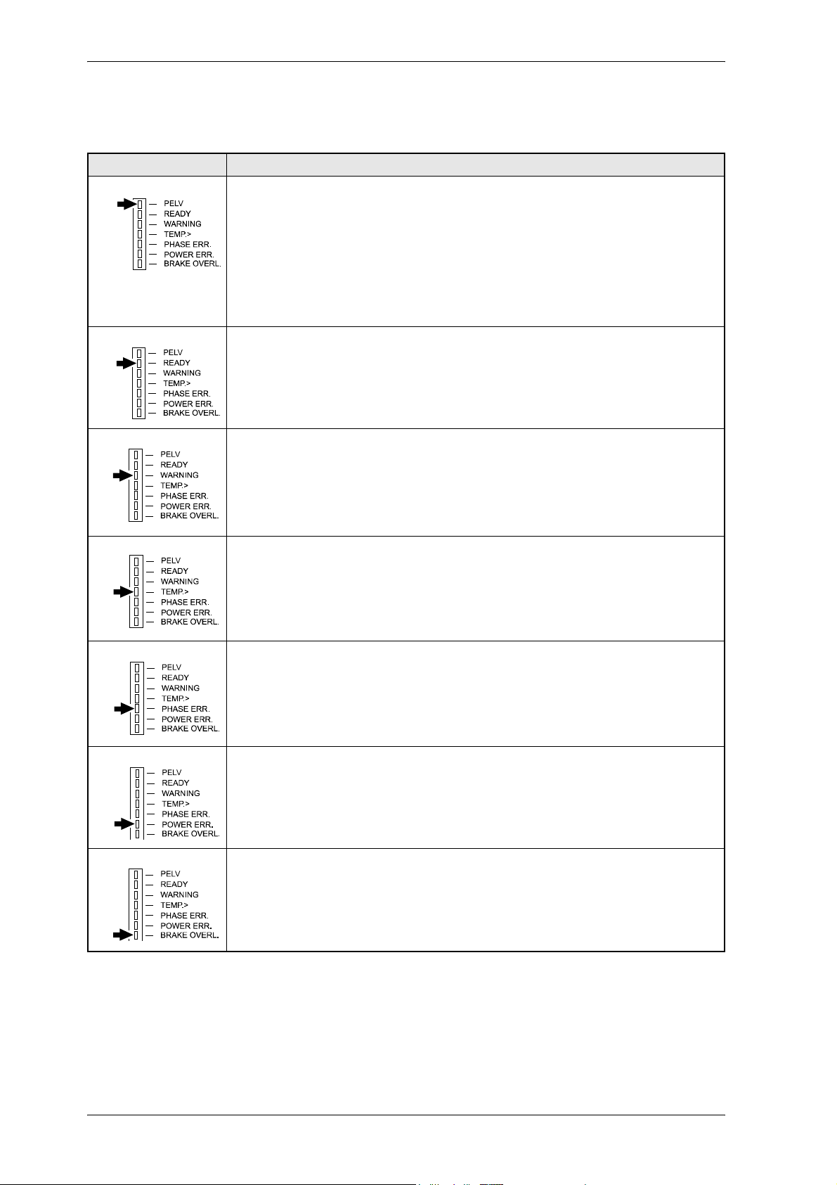
Commissioning
7.3.3 Messages via LEDs
LED Description
PELV Protective extra low voltage +24 V
green LED off:
At the terminals of plug-in terminal X99A are applied:
1,2: no +24 V
3,4: no 24 V ground
green LED on:
At the terminals of plug-in terminal X99A are applied:
1,2: +24 V
3,4: 24 V ground
READY
"Supply part ready"
green LED on:
The message ”Supply part ready” is activated.
Further information on this message can be obtained from ”Supply part ready” page 54
1)
WARNING
TEMP. > Overheat
PHASE ERR. Phase failure
POWER ERR. Mains failure
Warning
yellow LED on:
The WARNING message is activated.
”Phase failure monitoring function” page 56 and ”Mains failure monitoring function” page 56 will
inform you in which cases the message is activated.
The red LED is always off - it has no function in this unit.
red LED on:
The message ”Phase failure” is activated.
”Phase failure monitoring function” page 56 will inform you in which cases the message is activated.
red LED on:
The message ”Mains phase failure” is activated.
”Mains failure monitoring function” page 56 will inform you in which cases the message is activated.
1)
BRAKE OVERL. Short-circuit regenerative circuit output (Ba+ with Ba-)
red LED on:
The message "Short-circuit regenerative circuit output" is activated.
”Monitoring function of short-circuit regenerative circuit output” page 57 will inform you in which
cases the message is activated.
1. see also ”Messages via relay contacts” page 61.
60 Mono Power Unit BUM 62 T
5.99009.03 Baumüller Nürnberg GmbH
Page 61
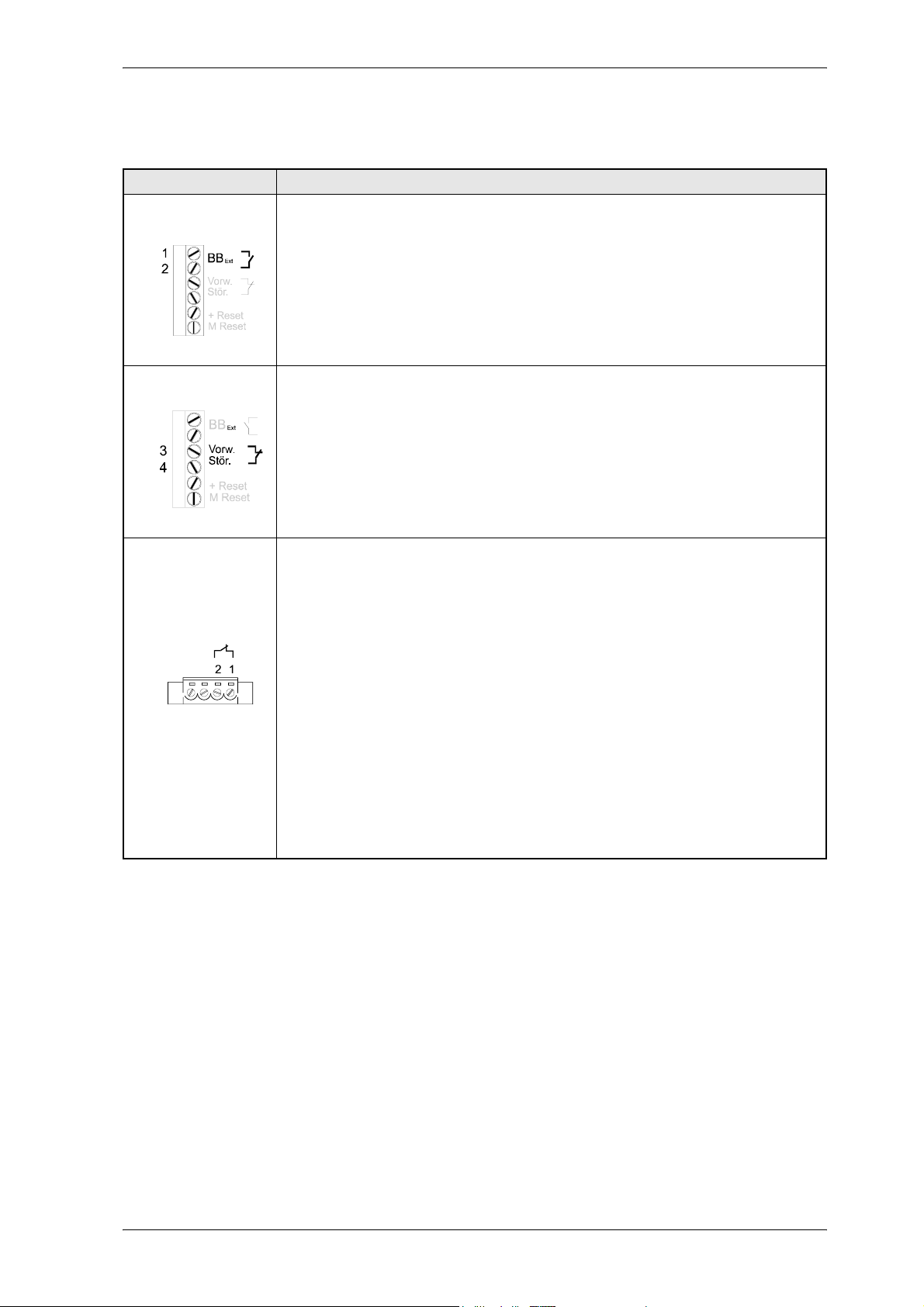
7.3.4 Messages via relay contacts
Plug-in terminal Description
X99AB
.
X99AB
"Supply part ready"
Contact open:
The message ”Supply part ready” is not activated.
Contact closed:
The message ”Supply part ready” is activated.
Further information on the message ”Supply part ready” can be obtained from ”Supply part ready”
page 54
Early warning - interference
Contact closed:
The WARNING message is not activated.
Contact open:
The WARNING message is activated.
”Phase failure monitoring function” page 56 and ”Mains failure monitoring function” page 56 will
inform you in which cases the message is activated.
For an immediate production restart, it is necessary to stop a drive electronically to achieve
the following:
y no contactors in the motor cables are necessary
y DC link voltage does not have to be switched off.
This requirement is met by using a safety relay.
Commissioning
X68
Feedback of safety relay (safety relay is available as an option)
Contact closed:
No +24 V supply for the safety relay. The power stage or the inverter is inhibited.
Contact open:
+24 V supply for the safety relay is applied. The power stage or the inverter can be triggered by the
controller.
If the +24V supply for the safety relay is no longer applied while the drive is running, the drive no
longer supplies a torque (i.e. there is no supply from the BUM 62 T).
To restart the drive, proceed as follows:
y Switch on +24 V supply for the safety relay
y Clear the existing message by a controller reset
Mono Power Unit BUM 62 T 61
Baumüller Nürnberg GmbH 5.99009.03
Page 62

Commissioning
62 Mono Power Unit BUM 62 T
5.99009.03 Baumüller Nürnberg GmbH
Page 63

Maintenance
8 MAINTENANCE
WARNING
This power unit carries dangerous voltage and contains dangerous rotating parts (fans). Ignoring the
safety and warning information may result in death, severe personal injury or damage to material
assets.
All maintenance and service work must only be carried out when the unit is de-energized.
Do not begin work on the DC link of the power unit until you have made sure that neither potential nor
voltage (residual charge) is applied.
When dismantling safety equipment during commissioning, repair and maintenance, ensure that the
machine is take out of commission in accordance with applicable regulations. Remount and check the
safety equipment immediately after completing commissioning, repair and maintenance work.
After carrying out any work on the machine –regardless of whether this involves the motor, the actual
value detection or the power unit – the owner must carry out acceptance testing of the entire drive and
document this chronologically in the machine log.
Failure to do this may result in the owner being faced with consequences relating to liability.
8.1 Maintenance information
The supplied power unit is free of maintenance.
Prohibition of unauthorized modifications
For safety reasons, you must not modify or add components on/to the drive.
Mono Power Unit BUM 62 T 63
Baumüller Nürnberg GmbH 5.99009.03
Page 64
Maintenance
8.2 Environmental conditions
If you keep to the environmental conditions during the entire period of storage, you can assume, that the
device will not be damaged.
WARNING
From six months storage period on, the capacitors are destroyed during commissioning, if they are not
reformed beforehand.
Reform the capacitors by supplying the device ready-for use for at least 48 hours with supply voltage,
but no impulse enable.
8.3 Recommissioning
Carry out commissioning as with a new device.
WARNING
From six months storage period on, the capacitors are destroyed during commissioning, if they are not
reformed beforehand.
Reform the capacitors by supplying the device ready-for use for at least 48 hours with supply voltage,
but no impulse enable.
64 Mono Power Unit BUM 62 T
5.99009.03 Baumüller Nürnberg GmbH
Page 65
Maintenance
8.4 Disposal
The units consist essentially of the following components and materials:
Component Material
diverse spacers, housing of the current
transformer and the fan, etc.
PCB on which the entire control
electronic is located.
Electronic elements may contain dangerous material.
If the components are used as directed, there is no danger for human beings or to the environment.
Hazardous materials may be created or released in case of fire.
Plastic
Basic material Epoxy resin glass fibrematerial, copper-plated on both
sides and interconnected;
diverse electronic components such as capacitors, resistors, relays,
semiconductor elements, etc.
Electronic components must not be opened, since beryllium oxide is used as internal insulation e.g. in
diverse semiconductors.
The beryllium dust set free when the components are opened, is dangerous to your health.
The units and modules must be recycled at the end of their service life.
If recycling is not possible dispose the units and modules according to the national regulations and the
regional and local ordinances.
Mono Power Unit BUM 62 T 65
Baumüller Nürnberg GmbH 5.99009.03
Page 66

Maintenance
66 Mono Power Unit BUM 62 T
5.99009.03 Baumüller Nürnberg GmbH
Page 67
Appendix
9 APPENDIX
9.1 Manufacturer Declaration
HERSTELLERERKLÄRUNG
IN SINNE DER
EG-MASCHINENRICHTLINIE 89/392/EWG, ANHANG IIB
Manufacturer Declaration in Accordance with
the EC-Machine Guidelines 89/392/EEC, Appendix II B
Hiermit erklären wir, daß es sich bei dieser Lieferung um die nachfolgend bezeichnete Maschinenkomponente handelt und dass ihre Inbetriebnahme solange untersagt ist, bis festgestellt wurde, dass die
Maschine, in die diese Komponente eingebaut ist, den Bestimmungen der EG-Maschinenrichtlinie 89/
392/EWG, Anhang II B entspricht.
We herewith declare that this delivery includes the following specified machine component and that its
putting into operation is prohibited until the declaration is made that the machine, in which this component is built in, complies with the regulations of the EC-machine guideline 89/392/EWG, appendix II B.
Bezeichnung der Maschinenkomponente:
Specification of the machine component:
Einzel-Leistungseinheit BUM 62 T.. / .. - .. - . - . - ...
Typenbezeichnung:
Type:
Mono Power Unit BUM 62 T 67
Baumüller Nürnberg GmbH 5.99009.03
Page 68
Appendix
9.2 Declaration of Conformity
KONFORMITÄTSERKLÄRUNG IM SINNE DER
EG-NIEDERSPANNUNGSRICHTLINIE 73/23/EWG
EG Declaration of conformity of equipment regarding low voltage directive 73/23/EWG
Bezeichnung der Maschinenkomponente: Typenbezeichnung:
Specification of the machine component: Type:
Einzel-Leistungseinheit BUM 62 T.. / .. - .. - . - . - ...
Die Übereinstimmung des bezeichneten Produkts mit den Vorschriften der Richtlinie wird nachgewie-
sen durch die Einhaltung folgender Normen:
Conformity of the significated product with the guidelines will be proved by following rules:
EN 50178: 1994 (VDE 0160/11.94)
„Ausrüstung von Starkstromanlagen mit elektronischen Betriebsmitteln“
EN 50178: 1994 (VDE 0160/11.94)
„Equipment of power installation concerned electronic operating materials“
68 Mono Power Unit BUM 62 T
5.99009.03 Baumüller Nürnberg GmbH
Page 69

9.3 General Conditions of Sale and Delivery
Appendix
1. Obligation and Conclusion of Contract
a) Deliveries of goods and provision of services shall be
effected exclusively based on these trading conditions.
They are an essential component of the contracts for
delivery and shall be considered as having been accepted
by the placing of an order. In the case of constant
business relations, they also apply for the future contracts.
b) Agreements diverging from the contract and verbal
collateral agreements shall only be binding if they have
been confirmed in writing by Baumüller Nürnberg GmbH
(hereinafter referred to as Baumüller). Diverging trading
conditions on the behalf of the purchaser shall be without
obligation, even where these have not been expressly
objected to. These General Conditions of Sale and
Delivery shall be considered as having been accepted by
the purchaser at the latest when the delivery is accepted.
c) In as far as deliveries of goods are subject to separate
external obligations in accordance with the Law
Concerning Foreign Trade and Payments with respect to
the Federal Office for Economics, the purchaser has to
observe the relevant conditions at his/her own
responsibility.
2. Price and Offers
Offers are subject to confirmation, not binding and apply
subject to material supply possibilities. Supplements and
amendments require written confirmation. Prices are ex
works and are subject to confirmation. Invoicing takes
place in accordance with the prices valid on the date of
delivery.
3. Extent of Delivery and Delivery Time
a) Specified delivery periods/dates are without obligation, in
as far as nothing else to the contrary has been expressly
agreed upon in writing. Delivery periods do not commence
until the purchaser has fulfilled all duties of co-operation,
in particular regarding details of performance. In the event
that the agreed deposits for orders are delayed, then the
delivery time shall be extended accordingly.
b) The purchaser is entitled, in particular in the event of a
delay in delivery of longer than 3 months, to set an
appropriate period of grace and after its expiry, to
withdraw from the order. Claims to compensation due to
non-fulfilment or delay shall be excluded, in as far as
Baumüller is not responsible for intent or gross
negligence.
c) Baumüller is entitled at any time to effect partial deliveries
and partial services, as well as to invoice these
accordingly
4. Delivery Problems
a) Delays/preventions in the delivery of goods or the
provision of services due to force majeure entitle
Baumüller to delay the production and delivery by the
duration of the obstruction plus an appropriate period of
time or to withdraw in part or in whole from the order.
b) Industrial disputes or other circumstances which
substantially impede or render impossible the delivery,
such as, in particular, disturbances in the operating
processes, problems in procuring materials, official
directives also apply as force majeure, irrespective of
whether they arise with regard to Baumüller or suppliers.
c) In these cases, Items 4 a), b), the purchaser shall have no
claim to compensation due to non-fulfilment or delay of
the delivery.
5. Packaging
Items for sale and delivery items are packaged and
transport insurance policies are taken out according to the
instructions of and at a cost to the purchaser. Upon
demand, the packaging material has to be returned
without delay, free of freight charges and expenses.
6. Dispatch and Passing of Risk
Deliveries shall be made ex works. The dispatch shall be
effected at a cost to and at the risk of the recipient of the
service/the purchaser. The risk passes to the recipient of
the delivery/purchaser as soon as the delivery items leave
the works. This shall apply at the latest, from the
transferral of the delivery items to the person carrying out
the transport, forwarding agent or carrier.
7. Warranty
In the event that a delivery item is defective, Baumüller
shall deliver an additional replacement or make a
subsequent improvement at its own choice. Multiple
subsequent improvements are permissible. Other
warranty claims on the behalf of the purchaser, in
particular also due to direct or indirect consequential
damage are excluded. The pre-condition for any warranty
is the normal contractual use of the delivery items. In the
event of the utilization of warranty services, the motor, the
replacement part or the device has to be sent in free of
freight charges, packaging costs or customs duties after
prior co-ordination with Baumüller. Baumüller is exempted
from any warranty if the party ordering returns the goods
complained about without prior co-ordination or contrary
to agreement. Warranty claims expire one month after
rejection of a defect on which notice is given, in as far as
the purchaser remains silent in this respect.
8. Notification of Defects
a) The purchaser shall examine the subject matter of the
contract and delivery items immediately and give notice of
any defects without delay, however, no later than 7 days
after receipt of the delivery. In case of non-obvious
defects notice has to be given in writing without delay after
their discovery, however, no later than 6 months from the
point of delivery. In the event that the purchaser does not
give notice of any defects in writing within this period of
time, then the subject matter of the contract shall be
considered as having been approved.
b) The purchaser shall allow Baumüller a suitable inspection
of defects of which notice is given and shall place all
necessary/requested technical information, in particular,
inspection records and test reports at Baumüller's
disposal. In the event that the purchaser fails to do so,
then the delivery items shall be considered as not having
been complained about and as being approved. In the
event that the purchaser alters the delivery items, then he/
she shall lose his/her warranty claims.
c) In the event of an established material defect or
performance defect, Baumüller can eliminate the defect or
supply a replacement. The purchaser can demand
rescission or a reduction after the expiry of an
appropriately set period of grace. Further claims on the
behalf of the purchaser, in particular to the reimbursement
of dismantling costs or installation costs are excluded. The
same applies to damages which do not affect the delivery
item itself.
d) Natural wear and tear and damage which arises after the
transferral of risk, in particular also due to incorrect or
Mono Power Unit BUM 62 T 69
Baumüller Nürnberg GmbH 5.99009.03
Page 70

Appendix
negligent handling, excessive demands or other unsuitable
use not in conformity with the contract are excluded from
the warranty. The same applies in particular for defects
which are attributable to atmospheric discharges,
overvoltages and chemical influences.
e) If no case of warranty is in existence or in the event
that this subsequently turns out to be the case, the
purchaser shall remunerate the utilization or the use of an
item or of a right, as well as services provided and
expenses to an appropriate amount. Baumüller is entitled
to a right of control as referred to in §§ 315 ff. BGB
[German Civil Code].
9. Liability
Contractual or legal claims on the behalf of the purchaser
against Baumüller are limited to intent and gross
negligence. This does not apply in as far as claims from
the ProdHaftG [Product Liability Act] have been enforced.
Baumüller shall only be held liable to the amount of the
damage foreseeable in accordance with the purpose of
the contract. Material damage which exceeds the value of
a delivery/service is not foreseeable in this sense. The
liability is limited in terms of amount to the remuneration
contractually owed.
10. Payments
a) Invoices are payable at the time agreed in the contract, at
the latest within 30 days after the invoice date, in cash and
without deductions. The purchaser can only offset with
claims which are final and absolute or undisputed. The
same applies to the exercising of rights of retention.
b) In the event of a delay in payment on the behalf of the
purchaser, interest to the rate of 4 % above the respective
minimum lending rate of the German Federal Bank,
however at least 10 % has to be paid without separate
proof being required.
c) Failure to comply with the terms of payment or
circumstances which endanger the credit worthiness of
the purchaser result in all claims immediately becoming
due. In these cases, deliveries shall only be made against
payment in advance.
d) Cash payments, bank transfers or cheque and bill
payments shall not be considered as payment/fulfilment of
the obligation before the amount due for payment has
been irrevocably received by Baumüller or credited to
Baumüller's account.
e) Payments have to be made directly to Baumüller. The
field staff are not entitled to accept payments or to issue
extensions or waivers without separate written authority.
11. Reservation of Ownership
a) The ownership of delivery items remains reserved up to
the fulfilment of all existing claims against the purchaser
from the business relation. Any bundling with other items
shall be effected by the purchaser for Baumüller. Then,
the entire product shall be considered as reserved goods.
b) The purchaser is entitled to sell the reserved goods in
orderly business transactions. All claims to which the
purchaser is entitled from this sale or other legal grounds
shall be assigned by him/her in advance to Baumüller.
Baumüller shall accept the assignment. In the event that
the reserved goods are bundled or sold with other items
standing in the possession of third parties, then the
assignment shall only apply to the amount of the invoice
value of the reserved goods. The purchaser is authorised
to collect these assigned claims. Upon request, he/she
has to make notice of the assignment to the debtor.
c) The purchaser shall inform Baumüller without delay of
impending and enforced access on the behalf of third
parties to the reserved goods or to the assigned claims.
The purchaser shall bear the costs incurred by this.
d) The authorization on the behalf of the purchaser to
dispose of the reserved goods and to collect assigned
claims expires in the event that the terms of payment are
not complied with, in particular, also in the case of bill and
cheque protests. In this case, Baumüller is entitled to take
possession of the reserved goods. The purchaser bears
the costs incurred by this. The taking back of goods shall
only represent a withdrawal from the contract when this is
expressly stated.
e) In the event that the value of the securities granted
exceeds the secured claims in terms of amount by more
than 20 %, then Baumüller shall renounce the securities
exceeding this value.
12. Drawings and Documentation
Baumüller is entitled to the exclusive property right and
copyright to cost estimates, drawings and all other
documentation. These documents may not be made
accessible to third parties without prior written consent. In
the event that a contract is not concluded, not
implemented or otherwise ended, then all documents
have to be returned immediately and unsolicited. There
shall be no right to retention to these documents.
13. Copyright (in particular Software / Licence)
a) Baumüller is exclusively entitled to all rights to the
software/edited versions, in particular property rights and
copyrights to the relinquished software, in particular for
the controlling of machines, systems and installations.
b) Baumüller grants the purchaser/buyer the non-exclusive,
non-transferable right to use the relinquished software in
the framework of the contractual purpose at the
contractually intended location/on the places in existence
at the time of purchase (single licence). The software shall
only be used on the associated purchased contractual
item. Any use extending beyond this is prohibited. In the
event of a use extending beyond this, Baumüller shall
have the rights referred to in Items 14 c), 14 d).
c) It is prohibited to make copies of the relinquished
software, whether in whole or in part, in as far as the
making of copies of the machine-readable material in the
framework of the required data backup or as copies for
internal company use has not separately been agreed
upon with prior written consent from Baumüller.
Processing of the relinquished software, in particular by
means of alteration, translation or by bundling with other
programs shall only be permitted after prior written
consent from Baumüller. Protection notices from
Baumüller on/in the software may not be removed and
also have to be adopted onto copies and edited versions.
Copies produced contrary to this condition shall come
under the possession and copyright of Baumüller.
Baumüller can prohibit the use of such copies and elect to
demand the immediate surrender or complete destruction
with proof of this destruction.
d) The buyer is not permitted to extend the licence in terms of
location/work places/machines/machine types or to grant
rights of utilization or grant sub-licences. The extension of
the licence shall be permitted by Baumüller exclusively
against a separate remuneration which has to be agreed
upon in writing.
14. Applicable Law
The law of the Federal Republic of Germany is
authoritative for all rights and obligations from and in
connection with this contract. The regulations of the UN
Sales Convention (CISG) are excluded.
70 Mono Power Unit BUM 62 T
5.99009.03 Baumüller Nürnberg GmbH
Page 71

Appendix
15. Place of Performance and Place of Jurisdiction
The place of performance for delivery and payment is the
seat of Baumüller. The place of jurisdiction for all
disputes from and in connection with this contract, in
particular also for cheque and bill liabilities is the seat of
Baumüller.
16. Miscellaneous
In the event that individual or several conditions of these
Conditions of Sale and Delivery should be or become
ineffective in part or in whole, then the validity of the
remaining conditions shall remain unaffected by this. The
parties shall complement/replace the ineffective or
incomplete condition with an appropriate regulation which
most extensively corresponds to the economic purpose of
the contractually desired regulation. The same applies for
the case of the presence of a gap in the regulations.
For the case that acceptance and installation are also
agreed upon, then the following conditions, Items 18 and
19 shall also apply:
17. Acceptance
a) The inspection of the delivery items ready for acceptance
shall take place in the Baumüller works. The purchaser
shall bear the costs of this inspection. In the event that the
purchaser fails to perform the inspection, then the delivery
items shall be considered as having been delivered in
conformity with the contract when they leave the works.
b) The purchaser is obliged to take delivery of goods and
services from Baumüller without delay. Immaterial defects
do not entitle the purchaser to refuse the acceptance.
c) In the event that the purchaser does not declare within 7
days after notification of the readiness for acceptance on
the behalf of Baumüller or after receipt of the contractual
service in writing and with exact, examinable specification
of reasons that he/she refuses the acceptance, then the
acceptance shall be considered as having been declared
and the orderly performance of the contract as having
been ascertained.
d) The agreed service shall be considered as having been
accepted when the item delivered has been put into
operation by the purchaser himself/herself or upon his/her
instructions by third parties beyond the functional test
required to carry out the acceptance. This also applies in
the event that the purchaser refuses the functional test/the
acceptance without sufficient cause.
e) Experts to be designated by both parties shall take part in
the acceptance inspection. The result of the functional test
shall be entered in a record to be signed by the purchaser
in consideration of the technical specifications.
18. Erection and Installation
Erection and installation shall only be effected in the case
of express agreement at the following further conditions:
a) The purchaser makes required workers and material
available at his/her own expense.
b) Before the commencement of installation works the
purchaser shall make available unsolicited all required
specifications, in particular concerning the location of
power lines which have been laid such that they are
hidden and similar installations, as well as the required
static specifications.
c) Before the commencement of the erection/installation, the
delivery items required for the commencement of works
have to be on site and all preliminary works progressed to
the extent that the erection/installation can immediately
begin and be completely carried out without interruption.
d) In the event that the erection, installation or putting into
operation is delayed due to circumstances for which
Baumüller is not responsible, then the purchaser shall
bear the costs for idle time and journeys required on the
behalf of the installation personnel.
e) The installation personnel working time has to be certified
weekly by the purchaser. The purchaser shall present to
the installation personnel a written certification regarding
the ending of the erection/installation without delay.
f) Baumüller shall not be held liable for the installation
personnel works, in as far as the works are not connected
to the delivery and the erection or installation.
g) Trial runs on systems not supplied by Baumüller shall not
be carried out by the installation personnel.
Mono Power Unit BUM 62 T 71
Baumüller Nürnberg GmbH 5.99009.03
Page 72

Appendix
9.4 Index
A
Accessories 47
Adding units 41, 44
Ambient temperature 13
Appendix 67
Assembly 19
automatic restart 56
automatic start 56
B
BB ext 54
BB int 54
C
Cabling 26
Commissioning 49
Conditions of Sale and Delivery 69
Connection diagram 39
Connection voltage 13
Connector assignment 42
Controller ready 53
D
DC link capacitor 13
Declaration of conformity 68
Dimensions 20
Disposal 65
E
EMC information 25
EMC Law 25
Environmental conditions 64
External ready 54
P
Phase failure monitoring 56
Plug-in terminal 43, 45
Pollution degree 19
Power loss 13
Power stage ready 53
R
Recommissioning 64
Reset not possible 56
S
Safe stop 33
Safety categories 34
Safety notes 7
Safety relay 34
Screening 29
Start drive 61
Supply part ready 53
T
Technical data 13, 33
Transport damage 17
Transportation 17
Type key 15
U
Unexpected ramp-up 33
Unpacking 17
F
Filter assembly 30
Filtering 30
Free space 19
G
Grounding 28
I
Index 72
Installation 23
Installation height 13
Internal ready 54
L
Leakage currents 30
Low-voltage supply 13
M
Mains failure monitoring 56
Maintenance 63
Maintenance information 63
Manufacturer Declaration 67
Maximum temperature 59
Monitoring of the regenerative circuit 57
Monitorings 58
O
Output power 13
Overheat 59
72 Mono Power Unit BUM 62 T
5.99009.03 Baumüller Nürnberg GmbH
Page 73

Page 74
Baumüller Nürnberg GmbH Ostendstraße 80-90 90482 Nürnberg T: +49(0)911-5432-0 F: +49(0)911-5432-130
All information given in this manual is customer information, subject to change without notice. We reserve the right to futher develop and actualize
our products continuously using our permanent revision service. Please notice, that specifications/data/information are current values according to the printing date.
These statements are not legally binding according to the measurement, computation and calculations. Before you make any information given in this manual to the basis
of your own calculations and/or applications, please make sure that you have the latest edition of the information in hand.
No liability can be accepted concerning the correctness of the information.
www.baumueller.de
 Loading...