


b maXX 3000
Table of contents
 Loading...
Instruction handbook
Language English
Translation
Document No. 5.11018.11
Part No. 441839
Status 05.03.2018
E
5.11018.11
b maXX 3000
BM3000
Mains rectifier
BM3200 / BM3300
Compact servo unit
Read the Instruction handbook before starting any work!

Copyright This Instruction handbook may be copied by the owner in any quantity, but only for internal
use. This Instruction handbook may not be copied or reproduced, in whole or in part, for any
other purposes.
The use and disclosure of information contained in this Instruction handbook are not permitted.
Designations and company marks contained in this Instruction handbook could be trademarks, the use of which by third parties for their own purposes could violate the rights of the
rights holder.
Preliminary information
Warning Insofar as this document is identified as being preliminary information, the following
applies:
this version is regarded as providing advance technical information to users of the described
devices and their functions at an early enough time in order to adapt to any possible changes
or expanded functionality.
This information must be regarded as being preliminary, as it has not yet passed through
Baumüller's internal review process. In particular, this information is still subject to changes,
thus no legal liability can be derived from this preliminary information. Baumüller assumes no
liability for damages that might arise from this possibly faulty or incomplete version.
If you detect or suspect any content errors and/or major form errors in this preliminary information, we request that you notify the Baumüller support specialist responsible for you.
Please provide us, via this employee, with your insights and comments so that we can take
them into account and include them when transitioning from the preliminary information to
the final information (as reviewed by Baumüller).
The conditions stipulated in the following section under "Obligatory" are invalid in case of preliminary information.
Obligatory This Instruction handbook are a part of the equipment/machine. This Instruction handbook
must be available to the operator at all times and must be in legible condition. If the equip
ment/machine is sold or moved another location, this Instruction handbook must be passed
on by the owner together with the equipment/machine.
After any sale of the equipment/machine, this original and all copies must be handed over to
the buyer. After disposal or any other end use, this original and all copies must be destroyed.
When the present Instruction handbook is handed over, corresponding sets of Instruction
handbooks of a previous version are automatically invalidated.
Please note that the specifications/data/information are current values according to the
printing date. These statements are not legally binding with regard to measurements,
computation or calculations.
Baumüller Nürnberg GmbH reserves the right, in developing its products further, to change
the technical specifications and handling of it products concerned without prior notice.
No liability can be accepted concerning the correctness of this Instruction handbook unless
otherwise specified in the General Conditions of Sale and Delivery.
-
Baumüller Nürnberg GmbH
Ostendstr. 80 - 90
90482 Nuremberg
Germany
Tel. +49 9 11 54 32 - 0
Fax: +49 9 11 54 32 - 1 30
Email : mail@baumueller.de
Internet: www.baumueller.de

Table of contents
1 General . . . . . . . . . . . . . . . . . . . . . . . . . . . . . . . . . . . . . . . . . . . . . . . . . . . . . . . . . . . . . . . . . . 7
1.1 Information on this Instruction handbook. . . . . . . . . . . . . . . . . . . . . . . . . . . . . . . . . . . . 7
1.2 Key to symbols . . . . . . . . . . . . . . . . . . . . . . . . . . . . . . . . . . . . . . . . . . . . . . . . . . . . . . . 7
1.3 Limitation of liability . . . . . . . . . . . . . . . . . . . . . . . . . . . . . . . . . . . . . . . . . . . . . . . . . . . . 8
1.4 Copyright protection. . . . . . . . . . . . . . . . . . . . . . . . . . . . . . . . . . . . . . . . . . . . . . . . . . . . 9
1.5 Applicable documents . . . . . . . . . . . . . . . . . . . . . . . . . . . . . . . . . . . . . . . . . . . . . . . . . . 9
1.6 Spare parts . . . . . . . . . . . . . . . . . . . . . . . . . . . . . . . . . . . . . . . . . . . . . . . . . . . . . . . . . 10
1.7 Disposal . . . . . . . . . . . . . . . . . . . . . . . . . . . . . . . . . . . . . . . . . . . . . . . . . . . . . . . . . . . . 10
1.8 Guarantee provisions. . . . . . . . . . . . . . . . . . . . . . . . . . . . . . . . . . . . . . . . . . . . . . . . . . 10
1.9 Customer service. . . . . . . . . . . . . . . . . . . . . . . . . . . . . . . . . . . . . . . . . . . . . . . . . . . . . 10
1.10 Terms used . . . . . . . . . . . . . . . . . . . . . . . . . . . . . . . . . . . . . . . . . . . . . . . . . . . . . . . . . 10
2 Safety . . . . . . . . . . . . . . . . . . . . . . . . . . . . . . . . . . . . . . . . . . . . . . . . . . . . . . . . . . . . . . . . . . 11
2.1 Contents of the Instruction handbook . . . . . . . . . . . . . . . . . . . . . . . . . . . . . . . . . . . . . 11
2.2 Changes and modifications to the device . . . . . . . . . . . . . . . . . . . . . . . . . . . . . . . . . . 11
2.3 Appropriate use . . . . . . . . . . . . . . . . . . . . . . . . . . . . . . . . . . . . . . . . . . . . . . . . . . . . . . 12
2.4 Responsibility of the operating company . . . . . . . . . . . . . . . . . . . . . . . . . . . . . . . . . . . 13
2.5 Protective devices . . . . . . . . . . . . . . . . . . . . . . . . . . . . . . . . . . . . . . . . . . . . . . . . . . . . 13
2.6 Training of the personnel . . . . . . . . . . . . . . . . . . . . . . . . . . . . . . . . . . . . . . . . . . . . . . . 14
2.7 Personal protective equipment . . . . . . . . . . . . . . . . . . . . . . . . . . . . . . . . . . . . . . . . . . 15
2.8 Special hazards . . . . . . . . . . . . . . . . . . . . . . . . . . . . . . . . . . . . . . . . . . . . . . . . . . . . . . 16
2.9 Fire fighting . . . . . . . . . . . . . . . . . . . . . . . . . . . . . . . . . . . . . . . . . . . . . . . . . . . . . . . . . 17
2.10 Safety equipment. . . . . . . . . . . . . . . . . . . . . . . . . . . . . . . . . . . . . . . . . . . . . . . . . . . . . 18
2.11 Behavior in hazardous situations or at accidents . . . . . . . . . . . . . . . . . . . . . . . . . . . . 18
2.12 Signs and labels . . . . . . . . . . . . . . . . . . . . . . . . . . . . . . . . . . . . . . . . . . . . . . . . . . . . . 19
3 Technical Data . . . . . . . . . . . . . . . . . . . . . . . . . . . . . . . . . . . . . . . . . . . . . . . . . . . . . . . . . . . 23
3.1 Dimensions . . . . . . . . . . . . . . . . . . . . . . . . . . . . . . . . . . . . . . . . . . . . . . . . . . . . . . . . . 23
3.1.1 Dimensions BM3000 . . . . . . . . . . . . . . . . . . . . . . . . . . . . . . . . . . . . . . . . . . . . . . . . . 24
3.1.2 Dimensions BM3200, BM3300 . . . . . . . . . . . . . . . . . . . . . . . . . . . . . . . . . . . . . . . . . 25
3.2 Weight . . . . . . . . . . . . . . . . . . . . . . . . . . . . . . . . . . . . . . . . . . . . . . . . . . . . . . . . . . . . . 25
3.3 Operating conditions . . . . . . . . . . . . . . . . . . . . . . . . . . . . . . . . . . . . . . . . . . . . . . . . . . 26
3.3.1 System types. . . . . . . . . . . . . . . . . . . . . . . . . . . . . . . . . . . . . . . . . . . . . . . . . . . . . . . 26
3.3.2 Requirements to the energy supply: power supply . . . . . . . . . . . . . . . . . . . . . . . . . . 27
3.3.3 Requirements to the control voltage / 24 V-supply . . . . . . . . . . . . . . . . . . . . . . . . . . 28
3.3.4 Requirements to the motor . . . . . . . . . . . . . . . . . . . . . . . . . . . . . . . . . . . . . . . . . . . . 28
3.3.5 Required environmental conditions. . . . . . . . . . . . . . . . . . . . . . . . . . . . . . . . . . . . . . 29
3.3.6 Correction factors at modified operational conditions . . . . . . . . . . . . . . . . . . . . . . . . 30
3.3.6.1 Installation altitude. . . . . . . . . . . . . . . . . . . . . . . . . . . . . . . . . . . . . . . . . . . . . . . . . . 30
3.3.6.2 Environmental temperature . . . . . . . . . . . . . . . . . . . . . . . . . . . . . . . . . . . . . . . . . . . 31
3.3.6.3 Supply voltage . . . . . . . . . . . . . . . . . . . . . . . . . . . . . . . . . . . . . . . . . . . . . . . . . . . . . 31
3.3.6.4 DC-link voltage . . . . . . . . . . . . . . . . . . . . . . . . . . . . . . . . . . . . . . . . . . . . . . . . . . . . 33
3.3.7 Cooling . . . . . . . . . . . . . . . . . . . . . . . . . . . . . . . . . . . . . . . . . . . . . . . . . . . . . . . . . . . 34
3.4 Electrical data . . . . . . . . . . . . . . . . . . . . . . . . . . . . . . . . . . . . . . . . . . . . . . . . . . . . . . . 35
3.4.1 Electrical data BM3002 . . . . . . . . . . . . . . . . . . . . . . . . . . . . . . . . . . . . . . . . . . . . . . . 35
3.4.2 Electrical data BM3X01-XT/BM3X11-XT. . . . . . . . . . . . . . . . . . . . . . . . . . . . . . . . . . 36
3.4.3 Electrical data BM3X02-XT, BM3X03-XT, BM3X04-XT, 400 V. . . . . . . . . . . . . . . . . 38
3.4.4 Electrical data BM3X12-XT, BM3X13-XT, 400 V . . . . . . . . . . . . . . . . . . . . . . . . . . . 40
3.4.5 Electrical data BM3XXX-XE, 230 V. . . . . . . . . . . . . . . . . . . . . . . . . . . . . . . . . . . . . . 42
3.4.6 Frequency-output-dependent current derating . . . . . . . . . . . . . . . . . . . . . . . . . . . . . 44
3.4.7 Load cycle according to EN61800-6 . . . . . . . . . . . . . . . . . . . . . . . . . . . . . . . . . . . . . 45
Instruction handbook b maXX BM3000, BM3200, BM3300
Document no. 5.11018.11
3
of 218

Table of contents
4 Design and Function . . . . . . . . . . . . . . . . . . . . . . . . . . . . . . . . . . . . . . . . . . . . . . . . . . . . . . 47
4.1 Design . . . . . . . . . . . . . . . . . . . . . . . . . . . . . . . . . . . . . . . . . . . . . . . . . . . . . . . . . . . . . 48
4.2 Identification of the device . . . . . . . . . . . . . . . . . . . . . . . . . . . . . . . . . . . . . . . . . . . . . . 50
4.2.1 Part number BM3200, BM3300 . . . . . . . . . . . . . . . . . . . . . . . . . . . . . . . . . . . . . . . . . 50
4.2.2 Type plate . . . . . . . . . . . . . . . . . . . . . . . . . . . . . . . . . . . . . . . . . . . . . . . . . . . . . . . . . 51
4.2.3 Type code . . . . . . . . . . . . . . . . . . . . . . . . . . . . . . . . . . . . . . . . . . . . . . . . . . . . . . . . . 53
4.3 UL notes . . . . . . . . . . . . . . . . . . . . . . . . . . . . . . . . . . . . . . . . . . . . . . . . . . . . . . . . . . . . 55
4.4 Display elements BM3000 . . . . . . . . . . . . . . . . . . . . . . . . . . . . . . . . . . . . . . . . . . . . . . 57
4.5 Display- and operating elements BM3200, BM3300 . . . . . . . . . . . . . . . . . . . . . . . . . . 58
4.5.1 Function of the 7-segment display. . . . . . . . . . . . . . . . . . . . . . . . . . . . . . . . . . . . . . . 62
4.5.2 Function of the LEDs H11 to H14 . . . . . . . . . . . . . . . . . . . . . . . . . . . . . . . . . . . . . . . 63
4.5.3 Function of the LEDs H31/H32 and H41/H42 . . . . . . . . . . . . . . . . . . . . . . . . . . . . . . 64
4.5.4 Settings address switches . . . . . . . . . . . . . . . . . . . . . . . . . . . . . . . . . . . . . . . . . . . . . 66
5 Transport and Packaging . . . . . . . . . . . . . . . . . . . . . . . . . . . . . . . . . . . . . . . . . . . . . . . . . . 71
5.1 Safety notes for transport . . . . . . . . . . . . . . . . . . . . . . . . . . . . . . . . . . . . . . . . . . . . . . . 71
5.2 What to observe when transporting . . . . . . . . . . . . . . . . . . . . . . . . . . . . . . . . . . . . . . . 71
5.3 Transport inspection. . . . . . . . . . . . . . . . . . . . . . . . . . . . . . . . . . . . . . . . . . . . . . . . . . . 72
5.4 Unpacking . . . . . . . . . . . . . . . . . . . . . . . . . . . . . . . . . . . . . . . . . . . . . . . . . . . . . . . . . . 72
5.5 Disposal of the packaging . . . . . . . . . . . . . . . . . . . . . . . . . . . . . . . . . . . . . . . . . . . . . . 72
6 Mounting . . . . . . . . . . . . . . . . . . . . . . . . . . . . . . . . . . . . . . . . . . . . . . . . . . . . . . . . . . . . . . . . 73
6.1 Safety notes . . . . . . . . . . . . . . . . . . . . . . . . . . . . . . . . . . . . . . . . . . . . . . . . . . . . . . . . . 73
6.2 Preparing for mounting. . . . . . . . . . . . . . . . . . . . . . . . . . . . . . . . . . . . . . . . . . . . . . . . . 76
6.3 Drilling templates . . . . . . . . . . . . . . . . . . . . . . . . . . . . . . . . . . . . . . . . . . . . . . . . . . . . . 77
6.4 Mounting instruction BM3000. . . . . . . . . . . . . . . . . . . . . . . . . . . . . . . . . . . . . . . . . . . . 80
6.5 Mounting instruction BM3200, BM3300 . . . . . . . . . . . . . . . . . . . . . . . . . . . . . . . . . . . . 83
7 Installation . . . . . . . . . . . . . . . . . . . . . . . . . . . . . . . . . . . . . . . . . . . . . . . . . . . . . . . . . . . . . . 85
7.1 Safety notes . . . . . . . . . . . . . . . . . . . . . . . . . . . . . . . . . . . . . . . . . . . . . . . . . . . . . . . . . 85
7.2 Voltage test . . . . . . . . . . . . . . . . . . . . . . . . . . . . . . . . . . . . . . . . . . . . . . . . . . . . . . . . . 87
7.3 Demands on the electrical power supply . . . . . . . . . . . . . . . . . . . . . . . . . . . . . . . . . . . 88
7.4 Requirements for the connection cables . . . . . . . . . . . . . . . . . . . . . . . . . . . . . . . . . . . 88
7.5 Protection of the device and accordingly of the cable . . . . . . . . . . . . . . . . . . . . . . . . . 88
7.6 PE connection and RCD compatibility . . . . . . . . . . . . . . . . . . . . . . . . . . . . . . . . . . . . . 89
7.7 Installation requirements with regard to EMC stability . . . . . . . . . . . . . . . . . . . . . . . . . 89
7.8 Shielding plan. . . . . . . . . . . . . . . . . . . . . . . . . . . . . . . . . . . . . . . . . . . . . . . . . . . . . . . . 90
7.8.1 Shielding connection mounting plate. . . . . . . . . . . . . . . . . . . . . . . . . . . . . . . . . . . . . 91
7.8.2 Shielding connection with shield sheet . . . . . . . . . . . . . . . . . . . . . . . . . . . . . . . . . . . 91
7.8.2.1 Mounting shield sheet . . . . . . . . . . . . . . . . . . . . . . . . . . . . . . . . . . . . . . . . . . . . . . . 91
7.8.2.2 Connecting the shield. . . . . . . . . . . . . . . . . . . . . . . . . . . . . . . . . . . . . . . . . . . . . . . . 92
7.9 Requirements for the motor temperature sensors . . . . . . . . . . . . . . . . . . . . . . . . . . . . 95
7.10 Installation procedure BM3000. . . . . . . . . . . . . . . . . . . . . . . . . . . . . . . . . . . . . . . . . . . 96
7.11 Installation procedure BM3200, BM3300 . . . . . . . . . . . . . . . . . . . . . . . . . . . . . . . . . . . 97
7.12 Connecting diagrams . . . . . . . . . . . . . . . . . . . . . . . . . . . . . . . . . . . . . . . . . . . . . . . . . . 98
7.12.1 Mains rectifier BM3000 . . . . . . . . . . . . . . . . . . . . . . . . . . . . . . . . . . . . . . . . . . . . . . . 99
7.12.2 BM3XXX-XT as a compact servo unit (3-phase) . . . . . . . . . . . . . . . . . . . . . . . . . . . 100
7.12.3 BM3XXX as an axis unit . . . . . . . . . . . . . . . . . . . . . . . . . . . . . . . . . . . . . . . . . . . . . 103
7.12.4 BM3XXX-XT as a compact servo unit (single-phase) . . . . . . . . . . . . . . . . . . . . . . . 108
7.12.5 BM3XXX-XE as compact servo unit (1-phase, 230 V). . . . . . . . . . . . . . . . . . . . . . . 111
7.12.6 Application: Power supply connection (3-phase) with energy compensation . . . . . 114
7.12.7 Application: DC link connection of further BM3000 or of additional capacities . . . . 116
4
of 218
Instruction handbook b maXX BM3000, BM3200, BM3300
Document no. 5.11018.11 Baumüller Nürnberg GmbH

Table of contents
7.13 Connections BM3000 . . . . . . . . . . . . . . . . . . . . . . . . . . . . . . . . . . . . . . . . . . . . . . . . 119
7.13.1 X100 input bridging relay. . . . . . . . . . . . . . . . . . . . . . . . . . . . . . . . . . . . . . . . . . . . . 119
7.13.2 Power connections . . . . . . . . . . . . . . . . . . . . . . . . . . . . . . . . . . . . . . . . . . . . . . . . . 119
7.14 Connections. . . . . . . . . . . . . . . . . . . . . . . . . . . . . . . . . . . . . . . . . . . . . . . . . . . . . . . . 120
7.14.1 BM3200, BM3300 front side . . . . . . . . . . . . . . . . . . . . . . . . . . . . . . . . . . . . . . . . . . 120
7.14.1.1 X1 - Service interface . . . . . . . . . . . . . . . . . . . . . . . . . . . . . . . . . . . . . . . . . . . . . . 120
7.14.1.2 X2 - Digital inputs/outputs . . . . . . . . . . . . . . . . . . . . . . . . . . . . . . . . . . . . . . . . . . . 121
7.14.1.3 X3 / X4 - fieldbus connection. . . . . . . . . . . . . . . . . . . . . . . . . . . . . . . . . . . . . . . . . 122
7.14.1.4 X6 - analog inputs/outputs . . . . . . . . . . . . . . . . . . . . . . . . . . . . . . . . . . . . . . . . . . . 126
7.14.1.5 X7 - encoder connection . . . . . . . . . . . . . . . . . . . . . . . . . . . . . . . . . . . . . . . . . . . . 127
7.14.2 Connections BM3200, BM3300 on top . . . . . . . . . . . . . . . . . . . . . . . . . . . . . . . . . . 133
7.14.2.1 X200 - 24V voltage supply. . . . . . . . . . . . . . . . . . . . . . . . . . . . . . . . . . . . . . . . . . . 137
7.14.2.2 X202, X203, X205 - power supply, DC link, ballast resistor connection . . . . . . . . 138
7.14.2.3 X300 - signal bus. . . . . . . . . . . . . . . . . . . . . . . . . . . . . . . . . . . . . . . . . . . . . . . . . . 140
7.14.3 Connections BM3200, BM3300 at the bottom. . . . . . . . . . . . . . . . . . . . . . . . . . . . . 142
7.14.3.1 X101 - motor temperature . . . . . . . . . . . . . . . . . . . . . . . . . . . . . . . . . . . . . . . . . . . 143
7.14.3.2 X102 - safe torque off - option . . . . . . . . . . . . . . . . . . . . . . . . . . . . . . . . . . . . . . . . 143
7.14.3.3 X107 - motor connection . . . . . . . . . . . . . . . . . . . . . . . . . . . . . . . . . . . . . . . . . . . . 144
7.14.4 PE connections BM3200, BM3300 rear panel . . . . . . . . . . . . . . . . . . . . . . . . . . . . 145
8 Operation . . . . . . . . . . . . . . . . . . . . . . . . . . . . . . . . . . . . . . . . . . . . . . . . . . . . . . . . . . . . . . 147
8.1 Safety notes. . . . . . . . . . . . . . . . . . . . . . . . . . . . . . . . . . . . . . . . . . . . . . . . . . . . . . . . 147
8.2 Bridging charge resistance BM3000 . . . . . . . . . . . . . . . . . . . . . . . . . . . . . . . . . . . . . 148
8.3 Operating concept BM3200, BM3300 . . . . . . . . . . . . . . . . . . . . . . . . . . . . . . . . . . . . 149
8.3.1 Enable signals. . . . . . . . . . . . . . . . . . . . . . . . . . . . . . . . . . . . . . . . . . . . . . . . . . . . . 149
8.3.2 Monitoring . . . . . . . . . . . . . . . . . . . . . . . . . . . . . . . . . . . . . . . . . . . . . . . . . . . . . . . . 149
8.3.3 Service interface . . . . . . . . . . . . . . . . . . . . . . . . . . . . . . . . . . . . . . . . . . . . . . . . . . . 150
8.4 DC-link load / switch-on frequency of power supply . . . . . . . . . . . . . . . . . . . . . . . . . 150
8.5 Optional safety function STO of BM3300 . . . . . . . . . . . . . . . . . . . . . . . . . . . . . . . . . 151
8.5.1 Safety notes according STO function (Safe Torque Off). . . . . . . . . . . . . . . . . . . . . 151
8.5.2 Safety levels and safety notes. . . . . . . . . . . . . . . . . . . . . . . . . . . . . . . . . . . . . . . . . 152
8.5.3 Function. . . . . . . . . . . . . . . . . . . . . . . . . . . . . . . . . . . . . . . . . . . . . . . . . . . . . . . . . . 153
8.5.4 Timing . . . . . . . . . . . . . . . . . . . . . . . . . . . . . . . . . . . . . . . . . . . . . . . . . . . . . . . . . . . 154
8.5.5 Supply with separate power supplies . . . . . . . . . . . . . . . . . . . . . . . . . . . . . . . . . . . 154
8.5.6 Examples for input wiring . . . . . . . . . . . . . . . . . . . . . . . . . . . . . . . . . . . . . . . . . . . . 155
8.6 Fieldbus communication . . . . . . . . . . . . . . . . . . . . . . . . . . . . . . . . . . . . . . . . . . . . . . 158
8.6.1 EtherCAT®. . . . . . . . . . . . . . . . . . . . . . . . . . . . . . . . . . . . . . . . . . . . . . . . . . . . . . . . 158
8.6.2 VARAN.. . . . . . . . . . . . . . . . . . . . . . . . . . . . . . . . . . . . . . . . . . . . . . . . . . . . . . . . . . 160
8.6.3 CANopen®. . . . . . . . . . . . . . . . . . . . . . . . . . . . . . . . . . . . . . . . . . . . . . . . . . . . . . . . 162
8.6.4 POWERLINK®. . . . . . . . . . . . . . . . . . . . . . . . . . . . . . . . . . . . . . . . . . . . . . . . . . . . . 164
9 Maintenance . . . . . . . . . . . . . . . . . . . . . . . . . . . . . . . . . . . . . . . . . . . . . . . . . . . . . . . . . . . . 165
9.1 Safety notes. . . . . . . . . . . . . . . . . . . . . . . . . . . . . . . . . . . . . . . . . . . . . . . . . . . . . . . . 165
9.2 Environmental conditions. . . . . . . . . . . . . . . . . . . . . . . . . . . . . . . . . . . . . . . . . . . . . . 165
9.3 Inspection intervals - maintenance notes . . . . . . . . . . . . . . . . . . . . . . . . . . . . . . . . . 166
9.3.1 Periodic maintenance . . . . . . . . . . . . . . . . . . . . . . . . . . . . . . . . . . . . . . . . . . . . . . . 167
9.4 Repairs . . . . . . . . . . . . . . . . . . . . . . . . . . . . . . . . . . . . . . . . . . . . . . . . . . . . . . . . . . . 170
10 Troubleshooting and Fault Correction. . . . . . . . . . . . . . . . . . . . . . . . . . . . . . . . . . . . . . . 171
10.1 Behavior in case of malfunctions . . . . . . . . . . . . . . . . . . . . . . . . . . . . . . . . . . . . . . . . 171
10.2 Monitoring functions. . . . . . . . . . . . . . . . . . . . . . . . . . . . . . . . . . . . . . . . . . . . . . . . . . 172
10.2.1 Monitoring functions . . . . . . . . . . . . . . . . . . . . . . . . . . . . . . . . . . . . . . . . . . . . . . . . 173
10.3 Error detection . . . . . . . . . . . . . . . . . . . . . . . . . . . . . . . . . . . . . . . . . . . . . . . . . . . . . . 175
10.4 Troubleshooting/error acknowledge . . . . . . . . . . . . . . . . . . . . . . . . . . . . . . . . . . . . . 175
Instruction handbook b maXX BM3000, BM3200, BM3300
Document no. 5.11018.11
5
of 218

Table of contents
11 Accessories and Spare Parts . . . . . . . . . . . . . . . . . . . . . . . . . . . . . . . . . . . . . . . . . . . . . . 177
11.1 Cables . . . . . . . . . . . . . . . . . . . . . . . . . . . . . . . . . . . . . . . . . . . . . . . . . . . . . . . . . . . . 177
11.1.1 Cable power supply-device . . . . . . . . . . . . . . . . . . . . . . . . . . . . . . . . . . . . . . . . . . . 177
11.1.2 Cable device-motor . . . . . . . . . . . . . . . . . . . . . . . . . . . . . . . . . . . . . . . . . . . . . . . . . 178
11.1.3 Hybrid cable device-encoder-motor. . . . . . . . . . . . . . . . . . . . . . . . . . . . . . . . . . . . . 178
11.1.4 Cable DC-link. . . . . . . . . . . . . . . . . . . . . . . . . . . . . . . . . . . . . . . . . . . . . . . . . . . . . . 180
11.1.5 Cable control power supply / signals . . . . . . . . . . . . . . . . . . . . . . . . . . . . . . . . . . . . 180
11.1.6 Cable signal bus . . . . . . . . . . . . . . . . . . . . . . . . . . . . . . . . . . . . . . . . . . . . . . . . . . . 181
11.1.7 Cables - EtherCAT®, VARAN, POWERLINK® . . . . . . . . . . . . . . . . . . . . . . . . . . . . 181
11.1.8 Accessories - CANopen®. . . . . . . . . . . . . . . . . . . . . . . . . . . . . . . . . . . . . . . . . . . . . 182
11.1.9 Cable service interface . . . . . . . . . . . . . . . . . . . . . . . . . . . . . . . . . . . . . . . . . . . . . . 182
11.1.10 Encoder cables . . . . . . . . . . . . . . . . . . . . . . . . . . . . . . . . . . . . . . . . . . . . . . . . . . . . 183
11.1.10.1 Connecting cable for Resolver . . . . . . . . . . . . . . . . . . . . . . . . . . . . . . . . . . . . . . . . 185
11.1.10.2 Connecting cable for encoder with HIPERFACE® . . . . . . . . . . . . . . . . . . . . . . . . . 186
11.1.10.3 Connecting cable for encoder with EnDat® or SSI. . . . . . . . . . . . . . . . . . . . . . . . . 187
11.1.10.4 Connecting cable for encoder with EnDat® 2.2 . . . . . . . . . . . . . . . . . . . . . . . . . . . 188
11.1.10.5 Connecting cable for sine/square-wave incremental encoder . . . . . . . . . . . . . . . . 190
11.2 Fuses . . . . . . . . . . . . . . . . . . . . . . . . . . . . . . . . . . . . . . . . . . . . . . . . . . . . . . . . . . . . . 191
11.2.1 Cable protection. . . . . . . . . . . . . . . . . . . . . . . . . . . . . . . . . . . . . . . . . . . . . . . . . . . . 191
11.2.2 Device protection . . . . . . . . . . . . . . . . . . . . . . . . . . . . . . . . . . . . . . . . . . . . . . . . . . . 191
11.2.3 Cable protection and device protection . . . . . . . . . . . . . . . . . . . . . . . . . . . . . . . . . . 192
11.3 Mains filter . . . . . . . . . . . . . . . . . . . . . . . . . . . . . . . . . . . . . . . . . . . . . . . . . . . . . . . . . 193
11.3.1 Required environmental conditions mains filter. . . . . . . . . . . . . . . . . . . . . . . . . . . . 193
11.3.2 Mains filter for 3-phase devices BM3XXX-XTXX. . . . . . . . . . . . . . . . . . . . . . . . . . . 193
11.3.3 Mains filter for 1-phase devices BM3XXX-XEXX. . . . . . . . . . . . . . . . . . . . . . . . . . . 195
11.4 Spare parts. . . . . . . . . . . . . . . . . . . . . . . . . . . . . . . . . . . . . . . . . . . . . . . . . . . . . . . . . 196
11.4.1 Connectors BM3200, BM3300. . . . . . . . . . . . . . . . . . . . . . . . . . . . . . . . . . . . . . . . . 196
11.4.2 Accessories kit shielding BM3200, BM3300 . . . . . . . . . . . . . . . . . . . . . . . . . . . . . . 197
11.4.3 Accessories kit protection cover BM3000 . . . . . . . . . . . . . . . . . . . . . . . . . . . . . . . . 197
12 Shutdown, Storage . . . . . . . . . . . . . . . . . . . . . . . . . . . . . . . . . . . . . . . . . . . . . . . . . . . . . . . 199
12.1 Safety instructions . . . . . . . . . . . . . . . . . . . . . . . . . . . . . . . . . . . . . . . . . . . . . . . . . . . 199
12.2 Requirements to the executing personnel . . . . . . . . . . . . . . . . . . . . . . . . . . . . . . . . . 200
12.3 Shutdown . . . . . . . . . . . . . . . . . . . . . . . . . . . . . . . . . . . . . . . . . . . . . . . . . . . . . . . . . . 200
12.4 Demounting . . . . . . . . . . . . . . . . . . . . . . . . . . . . . . . . . . . . . . . . . . . . . . . . . . . . . . . . 200
12.5 Storage conditions . . . . . . . . . . . . . . . . . . . . . . . . . . . . . . . . . . . . . . . . . . . . . . . . . . . 201
12.6 Recommissioning . . . . . . . . . . . . . . . . . . . . . . . . . . . . . . . . . . . . . . . . . . . . . . . . . . . . 202
13 Disposal. . . . . . . . . . . . . . . . . . . . . . . . . . . . . . . . . . . . . . . . . . . . . . . . . . . . . . . . . . . . . . . . 203
13.1 Safety regulations. . . . . . . . . . . . . . . . . . . . . . . . . . . . . . . . . . . . . . . . . . . . . . . . . . . . 203
13.2 Disposal facilities/authorities . . . . . . . . . . . . . . . . . . . . . . . . . . . . . . . . . . . . . . . . . . . 205
Appendix A - Abbreviations. . . . . . . . . . . . . . . . . . . . . . . . . . . . . . . . . . . . . . . . . . . . . . . . . . . . 207
Appendix B - Declaration of Conformity . . . . . . . . . . . . . . . . . . . . . . . . . . . . . . . . . . . . . . . . . 209
Table of figures. . . . . . . . . . . . . . . . . . . . . . . . . . . . . . . . . . . . . . . . . . . . . . . . . . . . . . . . . . . . . 213
Index . . . . . . . . . . . . . . . . . . . . . . . . . . . . . . . . . . . . . . . . . . . . . . . . . . . . . . . . . . . . . . . . . . . . . 215
Overview of Revisions . . . . . . . . . . . . . . . . . . . . . . . . . . . . . . . . . . . . . . . . . . . . . . . . . . . . . . . 217
6
of 218
Instruction handbook b maXX BM3000, BM3200, BM3300
Document no. 5.11018.11 Baumüller Nürnberg GmbH
1.1 Information on this Instruction handbook
This Instruction handbook provides important information on handling the device. A prerequisite for safe work is compliance with all specified safety notes and procedural instructions.
Additionally, the valid accident prevention regulations and general safety regulations applicable to the scope of application the device must be complied with.
Read this Instruction handbook, particularly the safety notes chapter, completely before
beginning any work on the device. This Instruction handbook is part of the product and
must be kept accessible to personnel at all times in the immediate vicinity of the device.
1.2 Key to symbols
Warning notes
Warning notes are identified by symbols in this Instruction handbook. The notes are introduced by signal words that express the extent of the danger.
It is imperative that these notes be complied with and are conscientiously regarded in order to prevent accidents, personal injury and material damage.
1GENERAL
DANGER!
....points out a directly dangerous situation, that will lead to severe injuries or death,
if not avoided.
WARNING!
....points out a potentially dangerous situation, that could lead to severe injuries or
death, if not avoided.
Instruction handbook b maXX BM3000, BM3200, BM3300
Document no. 5.11018.11
of 218
7
1.3
Recommendations
Limitation of liability
CAUTION!
....points out a potentially dangerous situation, that can lead to minor or slight injuries,
if not avoided.
NOTICE!
....points out a potentially dangerous situation, that can lead to material damage, if
not avoided.
NOTE!
....highlights useful hints and recommendations, as well as information for the effi-
cient and trouble-free use.
1.3 Limitation of liability
All specifications and notes in this Instruction handbook were compiled taking into account the applicable standards and regulations, the state of the art and our knowledge
and experience of many years.
The manufacturer assumes no liability for damages due to:
m noncompliance with the Instruction handbook
m usage for other than the intended purpose
m usage by untrained personnel
The actual scope of delivery can vary in case of optional equipment, laying claim to additional order options, or on account of the latest technical changes to the explanations and
representations described herein.
The user bears the responsibility for performing service and commissioning in accordance with the safety regulations of the applicable standards and all other relevant governmental or local regulations referring to the dimensioning and protection of conductors,
grounding, disconnectors, overcurrent protection, etc.
The person who carried out the mounting or installation is liable for any damage, which
incurred when assembling or connecting the device.
8
of 218
Instruction handbook b maXX BM3000, BM3200, BM3300
Document no. 5.11018.11 Baumüller Nürnberg GmbH
1.4 Copyright protection
General
1
The Instruction handbook must be treated confidentially
personnel who work with the device. The consignment of the Instruction handbook to third
persons without the written permission of the manufacturer is prohibited.
NOTE!
he specific contents, text, drawings, images and other representations are copy-
T
righted and subject to industrial property rights. Any prohibited usage is punishable
by law.
CANopen
EnDat
EtherCAT
HIPERFACE
HIPERFACE DSL
PROFINET
speedtec
®
®
®
®
is a registered trademark of PROFIBUS International
®
is a registered trademark of CAN in Automation e. V.
is a registered trademark of Dr. Johannes Heidenhain GmbH,
83301 Traunreut, Germany
is a registered trademark of Beckhoff Automation GmbH,
33415 Verl, Germany
is a registered trademark of SICK STEGMANN GmbH,
®
78166 Donaueschingen, Germany
is a registered trademark of INTERCONTEC Produkt GmbH
94559 Niederwinkling, Germany
. It is to be used exclusively by
NOTE!
Please note, that BAUMÜLLER is not responsible to examine whether any (industrial
property) rights of third parties are infringed by the application-specific use of the
BAUMÜLLER products/components or the execution.
1.5 Applicable documents
Components of other manufacturers are integrated into the device. For these purchased
parts, hazard assessments have been performed by the respective manufacturers. The
compliance of the design construction with the applicable European and national regulations has been declared for the components by the respective manufacturers.
Instruction handbook b maXX BM3000, BM3200, BM3300
Document no. 5.11018.11
9
of 218

1.6
Spare parts
1.6 Spare parts
1.7 Disposal
WARNING!
False or flawed spare parts can lead to damage, malfunction or complete fail-
ure, thus endangering safety.
Therefore:
m Only use original spare parts of the manufacturer.
Procure spare parts through an authorized dealer or directly from the manufacturer.
See also ZAccessories and Spare Parts– as from page 177.
Insofar as no take-back or disposal agreement has been made, please disassemble units
correctly and properly recycle the constituent parts.
See also ZDisposal– on page 203.
1.8 Guarantee provisions
The guarantee provisions are stated in a separate document of the sales documents.
The devices described herein may only be operated in accordance with the stipulated
methods, procedures and conditions. Anything else not presented here, including the operation of devices in mounted positions, is not permitted and must be cleared with the
plant on a case-by-case basis. If the devices are operated in any other manner than as
described within this Instruction handbook, then all guarantee and warranty rights are rendered null and void.
1.9 Customer service
Our customer service is available to provide you with technical information.
Info on the responsible contact persons is available at all times via telephone, fax, mail or
the Internet.
1.10 Terms used
The term „device“ or the item designation BM3XXX are also used in this documentation
for this Baumüller product „BM3000, BM3200, BM3300“. A list of the abbreviations used
can be found in ZAppendix A - Abbreviations– from page 207.
10
of 218
Instruction handbook b maXX BM3000, BM3200, BM3300
Document no. 5.11018.11 Baumüller Nürnberg GmbH

This section provides an overview of all of the important safety aspects for optimum protection of personnel as well as for the safe and problem-free operation.
2.1 Contents of the Instruction handbook
Each person who is tasked with performing work on or with the device must have read
and understood the Instruction handbook before working with the device. This also applies if the person involved with this kind of device or a similar one, or has been trained
by the manufacturer.
2.2 Changes and modifications to the device
In order to prevent hazards and to ensure optimum performance, no changes, additions
or modifications may be undertaken on the device that have not been explicitly approved
by the manufacturer.
2SAFETY
Instruction handbook b maXX BM3000, BM3200, BM3300
Document no. 5.11018.11
11
of 218
2.3
Appropriate use
2.3 Appropriate use
The device is conceived and constructed exclusively for usage compliant with its intended
purpose described in this Instruction handbook.
The devices of the model series BM3200, BM3300 contains of a power converter in combination with a servo controller. Devices are available in graduated design size and performance classes. The device BM3200, BM3300 is used exclusively as a converter for
controlling a motor.
The devices BM3000 are mains rectifier units to supply the DC link.
A device is considered as being used compliant with its intended purpose if all notes and
information of this Instruction handbook are adhered to.
WARNING!
Danger arising from usage for an unintended purpose!
Any usage that goes beyond the intended purpose and/or any non-compliant use of
the device can lead to dangerous situations.
Therefore:
m Only use the device compliant with its intended purpose.
m Observe all specifications of this Instruction handbook.
m Ensure that only qualified personnel work with/on this device.
m When configuring, ensure that the device is always operated within its specifica-
tions.
m Mount the device on a wall, which is sustainable.
m The device must always be operated within a control cabinet.
m Ensure that the power supply complies with the stipulated specifications.
m The device may only be operated in a technically flawless condition.
m Only operate the device in combination with components approved by Baumüller
Nürnberg GmbH.
m Only operate the devices in secondary surrounding (e.g. an industrial environ-
ment). The device has been developed in such a manner that it fulfills the requirements of the category C3 according to IEC 61800-3:2012. The device is not
intended to be connected to the public power supply. To operate the device in primary surrounding of the category C2/C1 (residential, business and commercial areas, directly on a public low-voltage power supply without an intermediate
transformer), special measures to reduce the transient emissions (line-internal and
radiated) must be provided for and certifiable by the system builder. Otherwise,
EMC interference could occur without such additional measures. Whether a device
described here can itself qualify for category C2/C1 with additional measures cannot be guaranteed.
12
of 218
Instruction handbook b maXX BM3000, BM3200, BM3300
Document no. 5.11018.11 Baumüller Nürnberg GmbH
2.4 Responsibility of the operating company
The device will be used in commercial areas. Thus, the proprietor of the device is subject
to the legal work safety regulations.
Along with the notes on work safety in this Instruction handbook, the safety, accident prevention and environmental protection regulations valid for the area of application of this
device must be complied with. Whereby:
e operating company must inform himself about the applicable work health and safe-
m Th
ty regulations and ascertain, in a hazard ass
arise from the special working conditions in the use area of the device. These must
then be implemented in the form of operating instruction for operation of the device.
is Instruction handbook must be kept accessible to personnel working with the de-
m Th
vice at all times in the immediate vicinity of the device.
e specifications of the Instruction handbook must be adhered to completely and
m Th
without exception.
e device may only be operated in a technically faultless and operationally safe con-
m Th
dition.
Safety
essment, any additional hazards that could
2
2.5 Protective devices
Mains rectifier
BM300X
Compact servo unit
BM320X, BM330X, BM321X, BM331X
All devices BM30
net to meet the IP code required in EN 61800-5-1, chapter 4.2.3.3 (BM300X: IP00,
BM3200, BM3300: IP 30: only upper horizontal surfaces; IP 20: all other surfaces).
DANGER!
Risk of fatal injury from electrical current!
The mains rectifier BM3000 protection code is IP00.
The operator is responsible for the protection against direct and indirect contact in the
switching cabinet.
IP code
IP 00
IP 20
00, BM3200, BM3300 must be installed in an appropriate control cabi-
There is an immediate risk of fatal injury if live electrical parts are contacted.
Therefore:
m The devices BM3200, BM3300 must be in operated inside of a control cabinet that
provides protection against direct contact of the devices and at least meets the requirements of EN 61800-5-1, Chapter 4.2.3.3.
Instruction handbook b maXX BM3000, BM3200, BM3300
Document no. 5.11018.11
of 218
13
2.6
Training of the personnel
2.6 Training of the personnel
WARNING!
Risk of injury due to insufficient qualifications!
Improper handling can lead to significant personal injury and material damage.
Therefore:
m Certain activities can only be performed by the persons stated in the respective
chapters of this Instruction handbook.
In this Instruction handbook, the following qualifications are stipulated for various areas
of activity:
m Operating personnel
n The drive system may only be operated by persons who have been specially trained,
familiarized and authorized.
n Troubleshooting, maintenance, cleaning, maintenance and replacement may only
be performed by trained or familiarized personnel. These persons must be familiar
with the Instruction handbook and act accordingly.
n Initial operation and training may only be performed by qualified personnel.
m Qualified personnel
n Electrical engineers authorized by Baumüller Nürnberg GmbH, and qualified electri-
cians of the customer or a third party who have learned to install and maintain
Baumüller drive systems and are authorized to ground and identify electrical power
circuits and devices in accordance with the safety engineering standards of the com
pany.
n Qualified personnel have had occupational training or instruction in accordance with
the respective locally applicable safety engineering standards for the upkeep and
use of appropriate safety equipment.
-
14
of 218
Instruction handbook b maXX BM3000, BM3200, BM3300
Document no. 5.11018.11 Baumüller Nürnberg GmbH
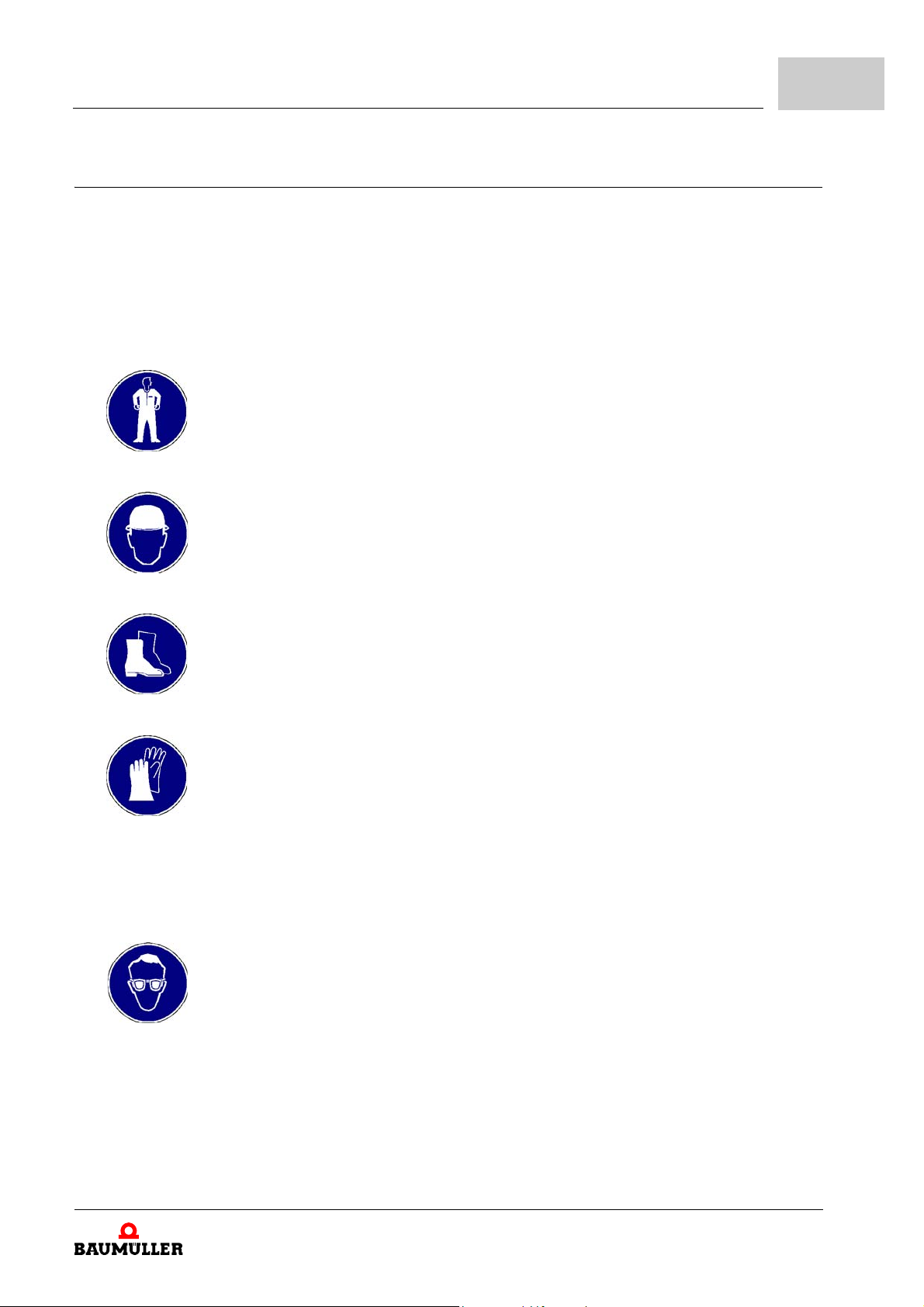
2.7 Personal protective equipment
The wearing of personal protective equipment is required when working in order to minimize health and safety risks.
m The protective equipment necessary for each respective type of work shall always be
worn during work.
m The personal safety signs present in each working area must be observed.
Protective work clothing
should be snug-fitting work clothes, with low tearing resistance, narrow sleeves and
with no extending parts. When having longer hair use a safety hair net.
No rings or chains should be worn.
Hard hat
to protect against parts falling down and against parts, which are flying around.
Safety
2
Wear for special
work.
Safety shoes
to protect against heavy objects falling down.
Safety gloves
to protect hands against friction, abrasion, puncturing or more severe injuries, as well
as against the contact with hot objects.
Safety goggles
to protect the eyes against objects, which are flying around and against splashes.
Instruction handbook b maXX BM3000, BM3200, BM3300
Document no. 5.11018.11
15
of 218
2.8
Special hazards
2.8 Special hazards
In the following section, the remaining marginal risks will be stated that have been identified as a result of the hazard analysis.
Observe the safety notes listed here and the warning notes in the further chapters of this
manual to reduce health risks and dangerous situations.
Electrical current
DANGER!
Risk of fatal injury from electrical current!
There is an immediate risk of fatal injury if live electrical parts are contacted. Damage
to the insulation or individual components can be life-threatening.
Therefore:
m Switch off the electrical power immediately in case of damage to the power supply
m Only allow work on the electrical system to be performed by qualified personnel.
m Switch off the current when any kind of work is being performed on the electrical
insulation.
system and ensure safety before switching on again.
Danger from
residual energy
DANGER!
Risk of fatal injury from electrical current!
Stored electric charge.
Discharge time of the rack system = discharge time of the device with the longest DC
link discharge time in the rack system.
Refer to ZElectrical data– from page 35.
Therefore:
m Do not touch electrically live parts before taking into account the discharge time of
the capacitors.
m Pay attention to the corresponding notes on the device.
m If several devices are connected e.g. with a rectifier unit, the DC link discharge can
take a much longer time. In this case, the necessary waiting period must itself be
determined or a measurement made to ensure the device is de-energized. This
discharge time must be posted, together with an IEC 60417-5036 (2002-10) warning symbol, on a clearly visible location of the control cabinet.
16
of 218
Instruction handbook b maXX BM3000, BM3200, BM3300
Document no. 5.11018.11 Baumüller Nürnberg GmbH
Moving components
2.9 Fire fighting
Safety
WARNING!
Risk of injury from moving components!
Rotating components and/or components moving linearly can result in severe injury.
Therefore:
m Do not touch moving components during operation.
m Do not open any covering during operation.
m The amount of residual mechanical energy depends on the application. Powered
components still turn/move for a certain length of time even after the power supply
has been switched off. Ensure that adequate safety measures are taken.
2
DANGER!
Risk of fatal injury from electrical current!
There is a risk of electric shock if an electrically-conductive, fire-extinguishing agent
is used.
Therefore:
m Use the following fire-extinguishing agent:
ABC powder / CO
2
Instruction handbook b maXX BM3000, BM3200, BM3300
Document no. 5.11018.11
17
of 218
2.10
Safety equipment
2.10 Safety equipment
WARNING!
Risk of fatal injury due to non-functional safety equipment!
Safety equipment provides for the highest level of safety in a facility. Even if safety
equipment makes work processes more awkward, under no circumstances may they
be circumvented. Safety can only be ensured by intact safety equipment.
Therefore:
m Before starting to work, check whether the safety equipment in good working order
and properly installed.
2.11 Behavior in hazardous situations or at accidents
Preventive
measures
And if something
does happen:
respond properly
m Always be prepared for accidents or fire!
m Keep first-aid equipment (e.g. first-aid kits, blankets, etc.) and fire extinguishers readily
accessible.
m Familiarize personnel with accident signalling systems, first aid equipment and life sav-
ing equipment.
m Stop operation of the device immediately with an EMERGENCY Stop.
m Initiate first aid measures.
m Evacuate persons from the danger zone.
m Notify the responsible persons of the site.
m Alarm medical personnel and/or the fire department.
m Keep access routes clear for rescue vehicles.
18
of 218
Instruction handbook b maXX BM3000, BM3200, BM3300
Document no. 5.11018.11 Baumüller Nürnberg GmbH
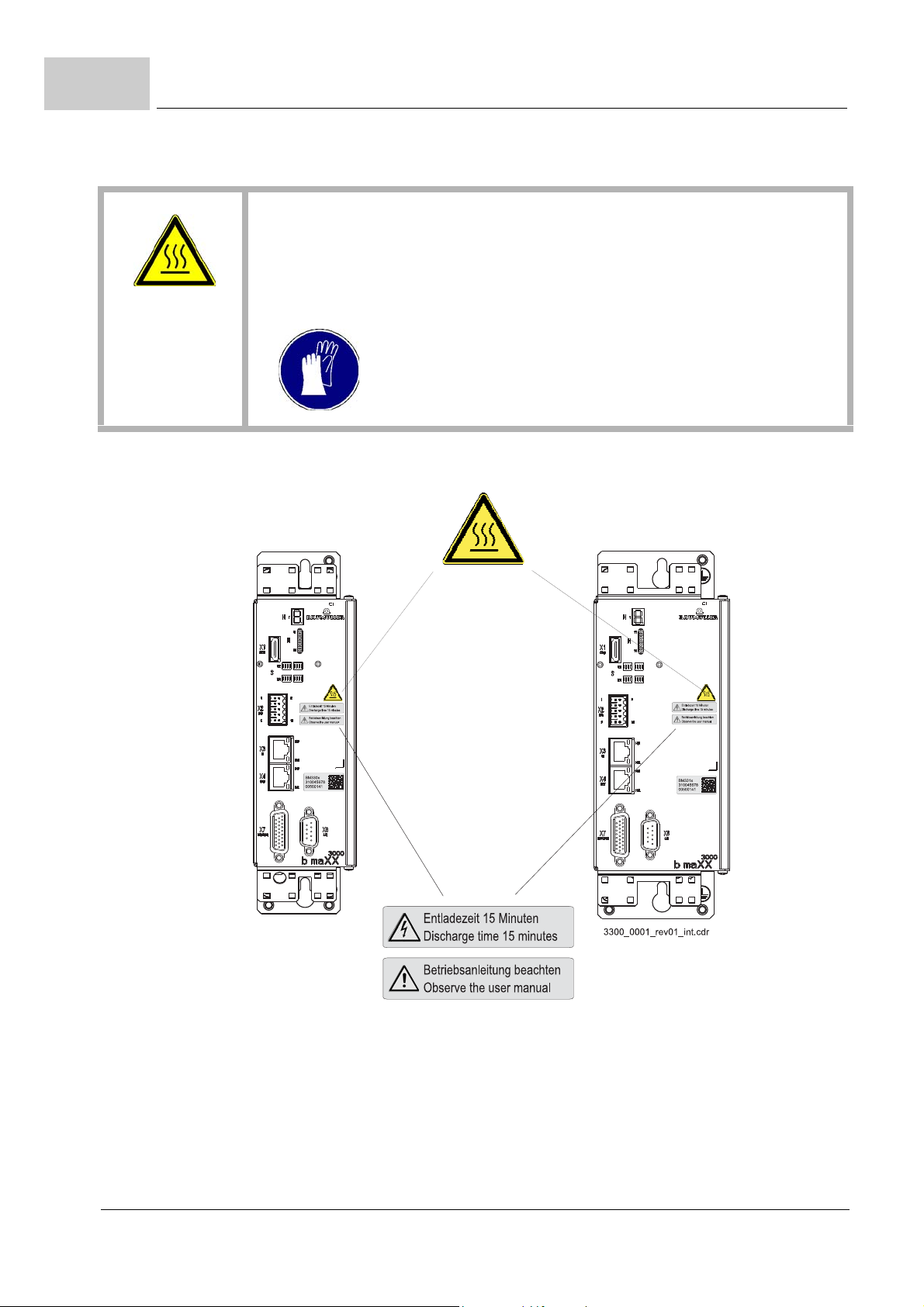
2.12 Signs and labels
The following symbols and information signs are located in the working area. They refer
to the adjacencies, where they were affixed.
WARNING!
Risk of injury due to illegible symbols!
Over the course of time, stickers and symbols on the device can become dirty or otherwise unrecognizable.
Therefore:
m Maintain all safety, warning and operating labels on the device in easily readable
condition.
Safety
2
Electrical voltage
Only qualified personnel may work in work areas that identified with this.
Unauthorized persons may not touch working materials marked correspondingly.
DANGER!
Risk of fatal injury from electrical current!
Stored electric charge.
Discharge time of the rack system = discharge time of the device with the longest DC
link discharge time in the rack system.
Refer to ZElectrical data– from page 35.
Therefore:
m Do not touch before taking into account the discharge time of the capacitors and
electrically live parts.
m Heed corresponding notes on the equipment.
m If several devices are connected e.g. with a rectifier unit, the DC link discharge can
take a much longer time. In this case, the necessary waiting period must itself be
determined or a measurement made to ensure the device is de-energized. This
discharge time must be posted, together with an IEC 60417-5036 (2002-10) warning symbol, on a clearly visible location of the control cabinet.
Instruction handbook b maXX BM3000, BM3200, BM3300
Document no. 5.11018.11
19
of 218
2.12
Signs and labels
CAUTION!
Risk of injury due to hot surface!
When in operation, the top of the device can heat up to temperatures > 70 °C!
Therefore:
m Wear safety gloves
20
of 218
Figure 1: Signs and labels BM3200, BM3300
Instruction handbook b maXX BM3000, BM3200, BM3300
Document no. 5.11018.11 Baumüller Nürnberg GmbH
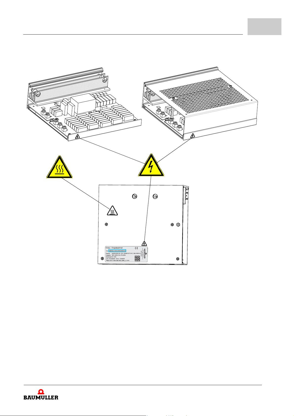
Without protection cover With protection cover (option)
Safety
2
Figure 2: Signs and labels BM3000
Instruction handbook b maXX BM3000, BM3200, BM3300
Document no. 5.11018.11
21
of 218
2.12
Signs and labels
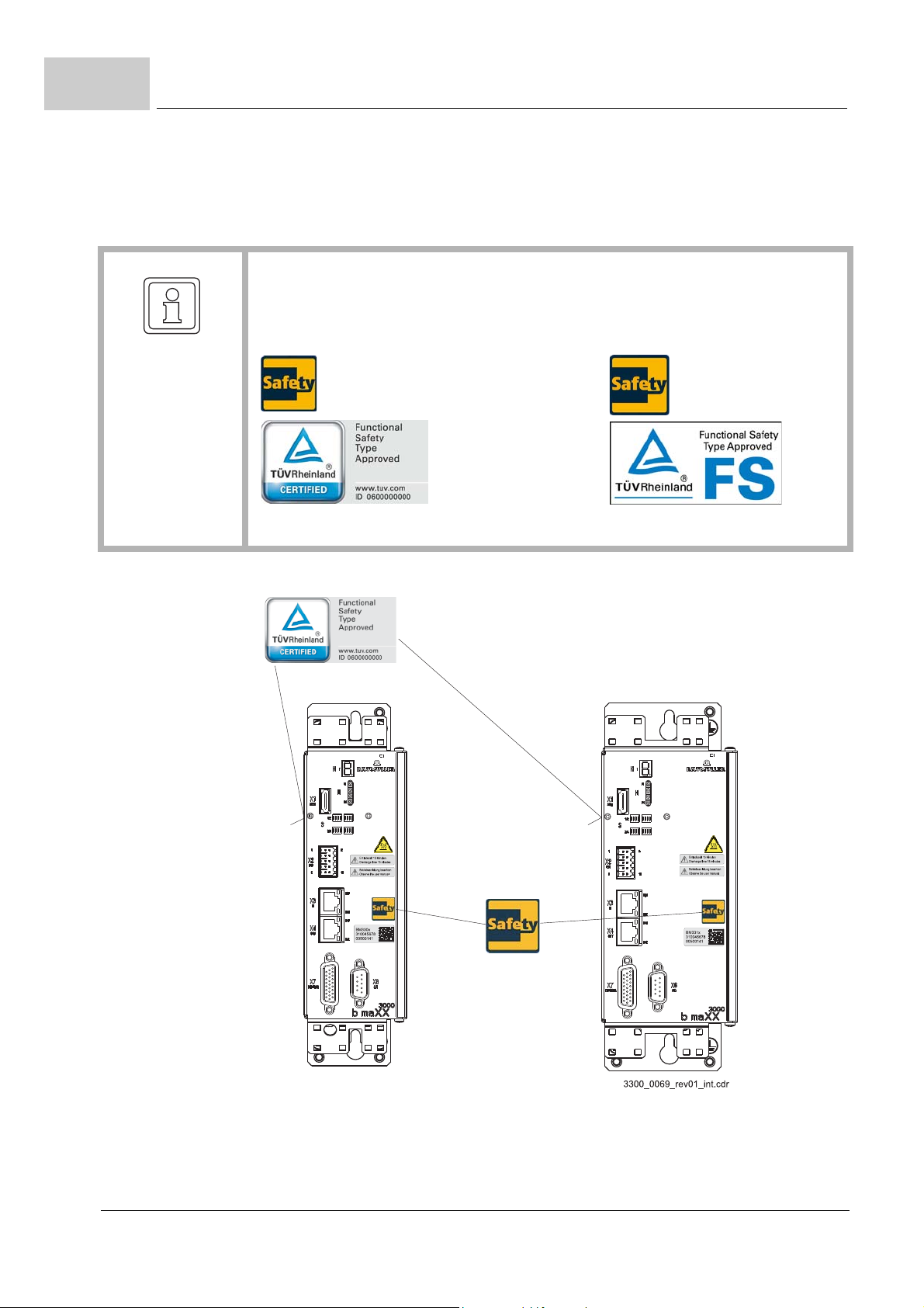
devices
with safety level
Signs and labels
NOTE!
Only a device marked with the TÜV Rheinland certification label and the safety label
fulfills a certified safety function within the meaning of PL classification according
ISO 13849 or SIL according EN 61800.
new logo former logo
22
of 218
Figure 3: Signs and labels BM3300 with safety level
Instruction handbook b maXX BM3000, BM3200, BM3300
Document no. 5.11018.11 Baumüller Nürnberg GmbH

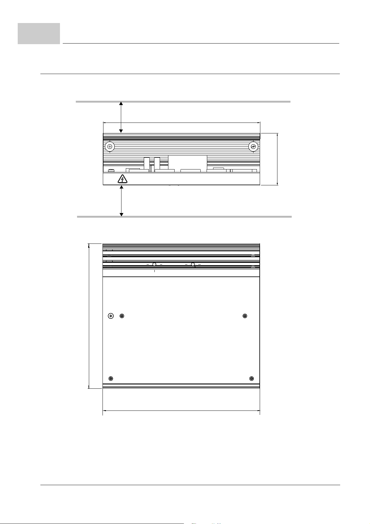
3.1 Dimensions
3TECHNICAL DATA
With the help of the following figures, the space requirements in the control cabinet are
determined. In order to execute the necessary drilling/section please refer to ZDrilling
templates– from page 77.
NOTE!
All dimensions in mm.
Instruction handbook b maXX BM3000, BM3200, BM3300
Document no. 5.11018.11
23
of 218
3.1
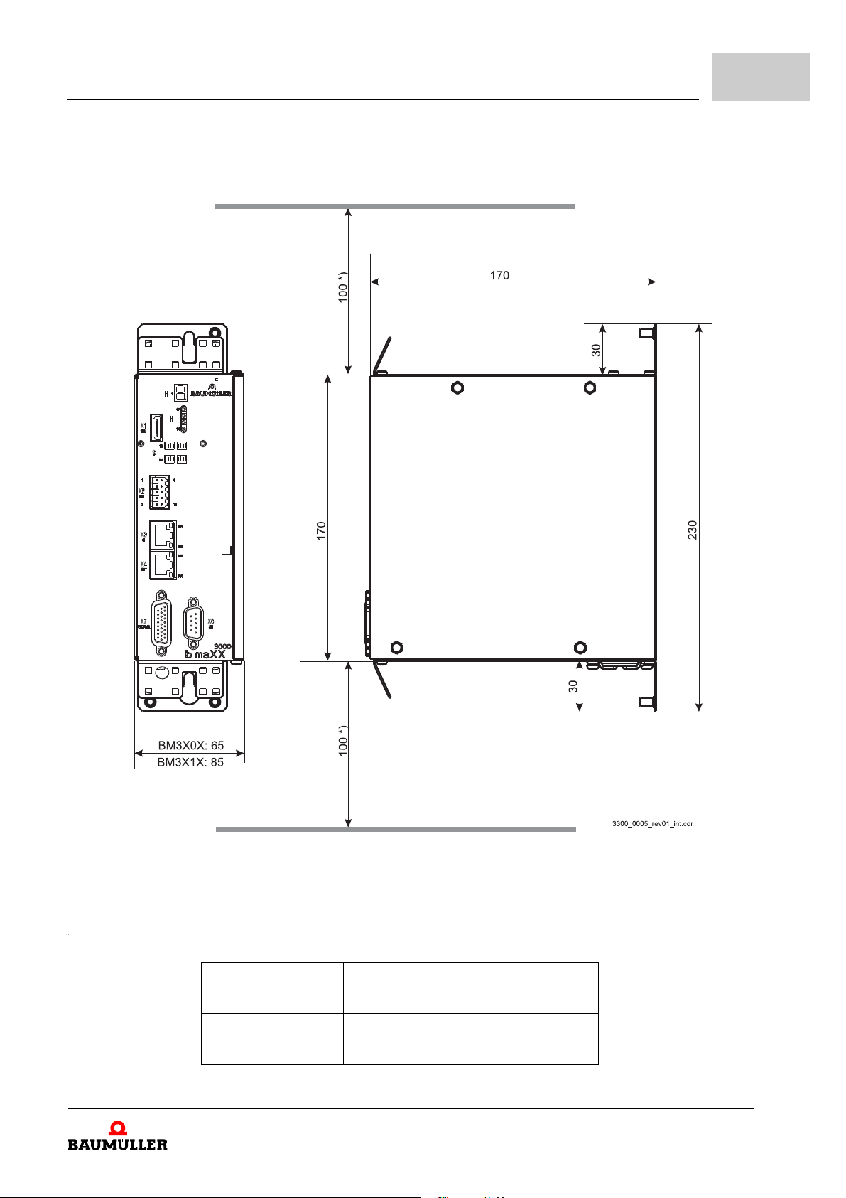
70
212
Dimensions
3.1.1 Dimensions BM3000
24
of 218
Figure 4: Dimensions BM3000
Instruction handbook b maXX BM3000, BM3200, BM3300
*) Consider minimum space,
ZCooling– on page 34.
Document no. 5.11018.11 Baumüller Nürnberg GmbH
3.1.2 Dimensions BM3200, BM3300
Technical Data
3
3.2 Weight
Figure 5: Dimensions BM3200, BM3300
Device Weight
BM3002 approximately 1.15 kg
BM320X, BM330X approximately 2.2 kg
BM321X, BM331X approximately 2.5 kg
Instruction handbook b maXX BM3000, BM3200, BM3300
*) Consider minimum space,
ZCoo
Document no. 5.11018.11
ling– on page 34.
25
of 218
3.3
Operating conditions
3.3 Operating conditions
3.3.1 System types
There is a differential structure of current supply networks and it is distinguished between
three basic types, referring to their grounding, which is accordant to DIN VDE0100 part
300 and accordingly to IEC 60364:
a TN-system one point is directly grounded (main ground). The cabinet of the elec-
m In
trical installation is connected via protective conductors and accordingly PE-conductors with this point.
a TT-system a point is directly grounded (main ground). The cabinet of the electric
m In
installation is connected to ground connections, which, however, are separated from
the main ground.
an IT-system there is no direct connection between active conductors (L1, L2, L3,
m In
N) and grounded parts (PE). The cabinets of the electrical installation are grounded.
The separation is reached, by the use of an isolating transformer or with the use of an
independent current source (generator, battery).
If there is an adequate low-impedance grounding within the TN- or the TT-network, then
line-side fuse is activated. A high-impedance grounding does not activate the fuse, so
a
that the ground currents (error current) can be potentially dangerous. For this reason, circuit breakers are used for the error current monitoring.
At a short-circuit to ground, no ground current can flow and the line-side fuses cannot be
activated, by which the operation can be kept up. Only a second short-circuit to ground at
another phase would cause an current error, which can trigger a fuse. In order to detect
the first short-circuit to ground an insulation monitor and for the second short-circuit to
ground, a current error monitoring, are necessary.
Supported system
pes
ty
NOTICE!
The operation of the BM3000 devices is possible with all power supply networks.
The operation of the BM3200, BM3300 devices is possible with TT- and TN-net-
works.
The common network types in the USA are differentiate clearly from the European
networks. Besides the Solidly Grounded Wye, which is similar to the TN-S-system,
there is also a Corner Grounded Delta (this differs to the description in the IEC). The
BM3200, BM3300 may not be operated here.
An operation with DC-link connection and use of a active mains rectifier is forbidden.
26
of 218
Instruction handbook b maXX BM3000, BM3200, BM3300
Document no. 5.11018.11 Baumüller Nürnberg GmbH

3.3.2 Requirements to the energy supply: power supply
Power supply
(also see ZSystem types– from page 26)
TN-/TT-system
Technical Data
BM3000 BM3200, BM3300
IT-system,
TN-/TT-system
3
Inductance (sum of supply inductance and the
power choke inductance)
Rated supply voltage/frequency
Absolute supply voltage minimum
Absolute supply voltage maximum
Absolute frequency minimum
Absolute frequency maximum
1) 2)
(UAC)
1) 2)
(U
ACmin
1) 2)
(U
ACmax
4)
4)
Overvoltage category
EN 61800-5-1, chapt. 4.3.6
Harmonic components (power supply voltage)
EN 61800-3, chapter 5.2.1, class 3
Power Supply voltage asymmetry
EN 61000-2-4, tab. 1, class 3
Commutation notch
EN 61800-3, chapter 5.2.1, class 3
Voltage drop
EN 61800-3:2004 and A1:2012
Voltage variations/deviations
EN 61200-2-4, Class 3
Control voltage
c
omplying with EN 61131-2:1994, table 7
3)
(UDC)
Max. short-circuit strength power supply
only necessary to comply with UL508C
Min. u
3 x 400 V, 50/60 Hz
= 0 %, max. uk = 4 %
k
1 x 230 V, 50/60 Hz
1 x 400 V, 50/60 Hz
3 x 400 V, 50/60 Hz
)
)
528 V / 50/60 Hz
/ 50/60 Hz
110 V
528 V / 50/60 Hz
47 Hz
63 Hz
III
THDU b 12 %
max. 3 %
setback depth < 40 %, area < 250 % x degree
10 % to 80 %
1)
+/-10 %
+10 % to -15 % at a time of b 1 min
-
-
+ 24 V -15 % / +20 %
5000 A
1)
If the voltage falls below U
2)
The rated voltage is 3 x 400 V
At lower supply voltages the output power of the device reduces, see correction factor at modified environmental conditions, ZSupply
voltage– on page 31.
3)
The control voltage must accord to PELV (EN 61800-5-1, chapter 3.21) and accordingly SELV (EN 61800-5-1, chapter 3.35).
At a control voltage < 24 V the ventilator power is reduced. Therefore, it can be necessary, that the output currents also be reduced.
4)
Rate of change of system frequency max. 1 Hz/s (EN 61000-2-4, class 3)
for t > 0,1 s the error „Power unit not ready-to-operate“ is generated.
ACmin
Instruction handbook b maXX BM3000, BM3200, BM3300
Document no. 5.11018.11
27
of 218
3.3
BM3200
BM3300
BM3200
BM3300
BM3200
BM3300
BM3200
BM3300
Operating conditions
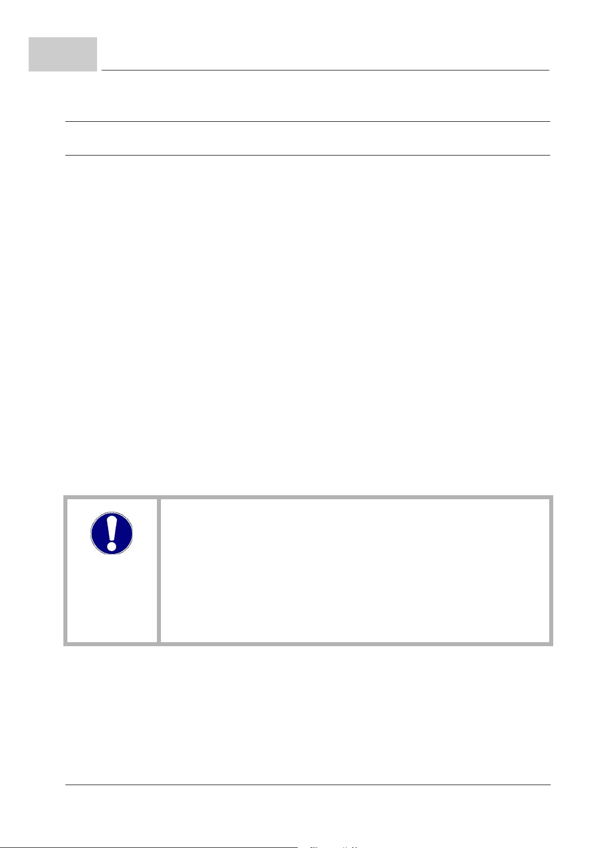
3.3.3 Requirements to the control voltage / 24 V-supply
Figure 6: Control voltage / 24V-supply
The power supply for the 24 V supply voltage must provide the rated power, at least,
which accords to the sum of the 24 V-supply voltage of all devices.
3.3.4 Requirements to the motor
The BM3200, BM3300 was prepared for the operation of three-phase motors with a motor terminal voltage of 3 x 350 V (typical for servo motors of Baumüller) or 3 x 400 V (typical for standard asynchronous motors and for customer-specific special motors of
Baumüller). The motors are to be operated wye-connected. The rated DC-link voltage is
540 V
. In braking operation it must be expected, that the DC-link voltage increases to
DC
780 V or 800 V. The connected motor must be constructed for these DC-link voltages.
The use of the devices is also possible at smaller voltages, e.g. 3 x 230 V. However, this
implies that the used three-current motors for the operation at inverters with a voltage of
up to 800 V DC-link voltage are designed, because the ballast resistor voltage threshold
remains unchanged (see ZElectrical data– from page 35). Thus, in these cases, threephase motors with U
DC rated
540 V, must be used, only.
28
of 218
Instruction handbook b maXX BM3000, BM3200, BM3300
Document no. 5.11018.11 Baumüller Nürnberg GmbH

Technical Data
3.3.5 Required environmental conditions
BM3000 BM3200, BM3300
Transportation temperature range -25 °C to +70 °C
3
Transportation climate classification
EN 60721-3-2
2 K 3
Storage temperature range -25 °C to +55 °C
Storage climate classification
EN 60721-3-1
Operation environment Industrial supply network
1 K 4
1)
Operation temperature range min. 5 °C to max. 40 °C min. 5 °C to max. 55 °C
(with derating above 40 °C)
2)
Operation climate classification
EN 60721-3-3
Installation altitude up to 2000 m altitude
(with derating above 1000 m)
Humidity (operation)
EN 60721-3-3
relative humidity: 5 % to 85 % non-condensing
absolute humidity: 1 g/m
3 K 3
and
3
to 25 g/m
3)
3
Ionizing and non-ionizing radiation < measurable range
Vibration, shock and repetitive shock
EN 61800-5-1, section 5.2.6.4 vibration test
Pollution degree
EN 61800-5-1, table 6, tab. 2
max. 0.5 g operating (1 g tested)
2
1)
For an operation in an environment of category C2 according to IEC 61800-3:2012 additional measures may be required.
In this case the system manufacturer/operator must provide evidence, that these additional measures are effective and that the limit
values specified in IEC 61800-3 of category C2 are complied with.
2)
See correction factors at modified environment conditions, ZEnvironmental temperature– on page 31.
3)
See correction factors at modified environment conditions, ZInstallation altitude– on page 30.
NOTICE!
Normally, only non-conductive pollution occurs. Any conductive pollution, if for a
short-term or permanently, is forbidden and can cause the destruction of the device.
The customer is responsible for destructions, which are caused by conductive materials.
Instruction handbook b maXX BM3000, BM3200, BM3300
Document no. 5.11018.11
29
of 218
3.3
3.3.6 Correction factors at modified operational conditions
3.3.6.1 Installation altitude
Operating conditions
If the devices BM3200, BM3300 are used at operational conditions, which cause different
correction factors, then all correction factors for the permitted output power and accordingly the output current, must be taken into account by multiplication at the same time.
The following correction factors are to be considered if nothing other is specified at the
„Technical data“ of the device:
NOTE!
The temperature of the cold plate temperature must be higher or equal to the surrounding temperature to prevent condensation.
NOTE!
It is no derating necessary while single phase operation of a three phase device
BM3201-XT, BM3301X-XT.
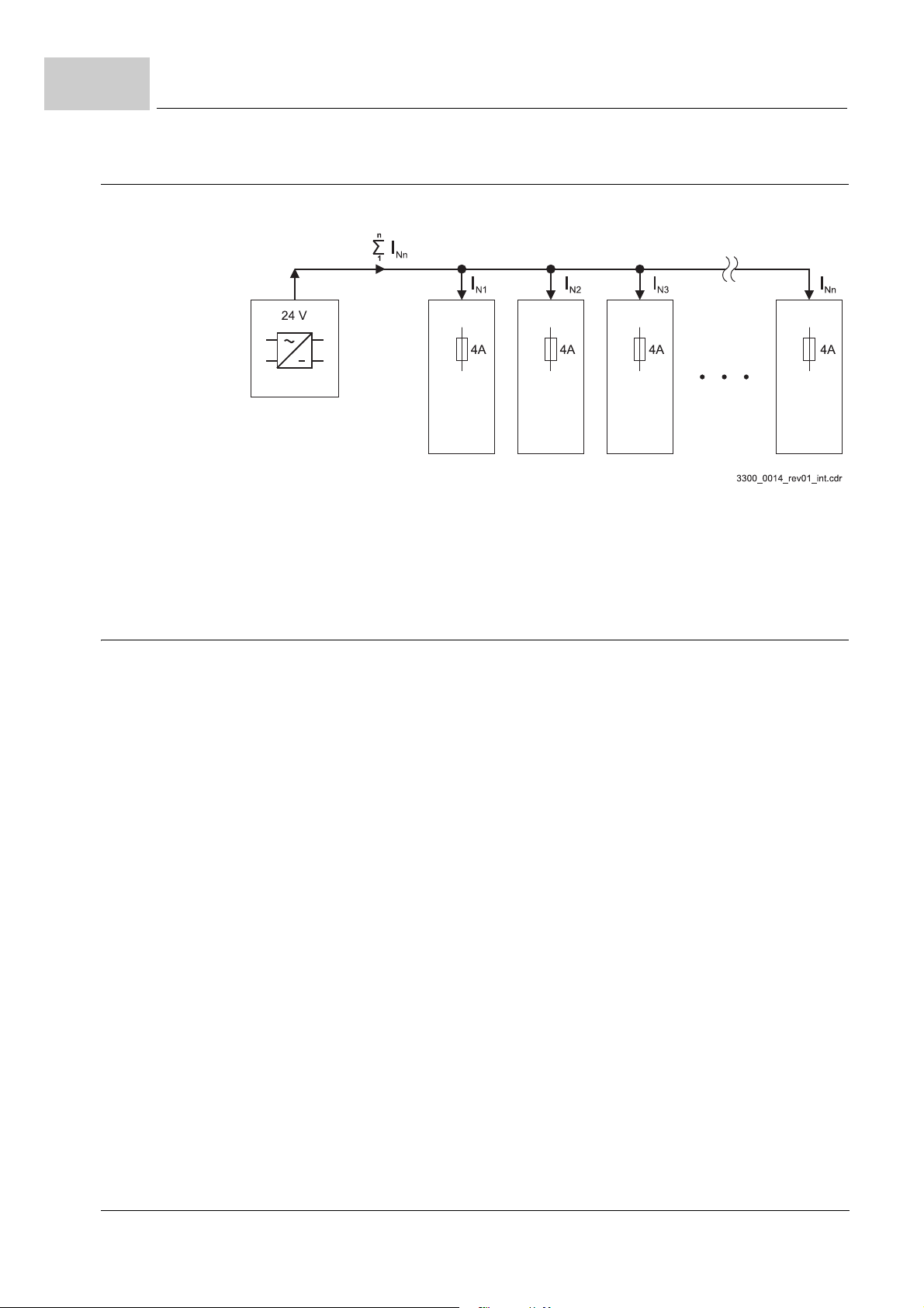
The output power must be reduced against the rated power, according to the following
figure, if the devices BM3000, BM3200, BM3300 are used above an altitude of 1000 m,
no operation is permitted above an altitude of 2000 m.
Rated Power
Output Power
Altitude
30
of 218
Figure 7: Reducing of output power in dependence of altitude
Instruction handbook b maXX BM3000, BM3200, BM3300
Document no. 5.11018.11 Baumüller Nürnberg GmbH
Loading...