

Page 1
Section 1 - How to Rebuild a Baumfolder
NOTE: There are several bolts with the same diameter and thread but different lengths.
Do not interchange bolts of different lengths. The length is very important.
1. Before working on the folder: DISCONNECT ALL ELECTRICAL POWER
SUPPLY TO THE FOLDER to prevent accidental start of the folder. Check level
across the number one roller and from front to back of left and right frame. Check to
insure you have all the parts and tools necessary such as reamers, gauges, and etc. It is
2. Remove all guards covering area where you are working. If side guard you are removing
3. Remove drive belts. If you are not familiar with the equipment, I
4. Remove the drive gears on the outside of the frame
5. Remove fold plates on the section you are working
6. To remove the fold rolls, loosen the set screw in the collar
7. Make a note of the location of the witness marks for
helpful to clean area around the folder so if you drop anything, it will be easier to find.
has electrical wires in it, do not stretch the wires. The wire may pull out of the terminal
and cause a short when you check the folder. Normally the wires are long enough that the
controls can be placed in a position where it is out of the way while working on the
folder. You may have to remove the hand wheel on the 500 series to allow the wires to
pass between the frame and the throw off rod. Caution should be exercised when
replacing the guard not to pinch lead wires between the guard and the frame causing a
short in the electrical system.
suggest you put tape on the belt and identify its location for later
convenience.
on the non-operator side of the folder section you
are working on. Use your parts book if you have
trouble remembering how it goes back or draw a
sketch for future reference.
on. Store them in a manor that the nose of the fold
plate or the plate itself is not damaged.
of each fold roll (usually on the left end of the fold roll)
and move collar toward the body of the fold roll.
future reference. You can achieve the proper space
between the fold rolls with the eccentrics 180 degrees off
until you get to the number 5 fold roll. You want to know
where to start when setting the rollers.
8. Do not remove the plate rails or if applicable the eccentric deflector studs. You can
remove the fold rollers with the rails and studs in place. This will save time later when
setting fold plates.
Section 1 - Page 1
Page 2
Section 1 - How to Rebuild a Baumfolder..... continued
9. It is not necessary to remove the register table to change the fold rollers, but I recommend
it to allow better access when removing rollers and later when setting the eccentrics and
fold plate setting on # 2 and # 4 plate and rolls.
10. To remove register table:
A) Remove paper hold downs
B) Remove tuck in shoes.
C) Remove marbles from marble guide.
D) Remove marble guide.
E) Remove side guide. Slide register belt under marble guide
over to get to the flat head screws that fastens the side guide.
F) Remove tape tighten assembly. (under register table) loosen
2 bolts on each end and slide assembly toward operator side
from above the belts and below the register table.
G) Remove taper plate between feeder and register tapes (a flat head screw on each
end.)
H) Lift up on the large tape roll, (by feeder), on the non-operator side of the folder
and slide it toward you to remove it.
I) Have two people, one on each side of the register to hold the register while
removing the four bolts that fastens it to the frame. Then lower the end toward the
feeder down and forward and lift up the opposite end until the register clears the
Baumsets/ roller adjustment stems. Then lift the register to a safe location where it
will not be damaged.
J) To replace register when finished, reverse procedure I through A.
11. Remove slitter shafts.
12. Remove all tension block bolts. Ten (five on
each side) on a three or four plate folder, six
(three on each side on a two plate folder.
13. If the folder has oil lines, remove oil lines from
the roll boxing and main drive roll.
Remove the clip that fastens the oil lines to the
frame on the operator side just above the number
one roller.
14. Remove the right and left roll boxing eccentric
from the number one fold roller. (Note: these
eccentric bolts are usually fine thread. Most of
the other bolts are course thread.) Lift the
number one roll up and out of the folder.
15. Continue step number 14 on the #2, then #4,
then #5, then#3 rollers in that order. Rollers
number 5 and 3 should come under the roll
bank and toward the delivery end of the roll bank to remove.
16. Remove hand wheel on operator side of the folder. If the hand wheel is not free of the
fold rollers, it should be left off or replaced by one that engaged when you want to turn
the folder by hand.
Section 1 - Page 2
Page 3
Section 1 - How to Rebuild a Baumfolder..... continued
17. Remove the three flat head bolts on the main drive roll sleeve on the operator side of the
folder. Remove the main drive roll sleeve, and slide the main drive roll out through the
opening in the frame.
18. Remove the left hand main drive roll sleeve.
(Caution) mark the main drive roll sleeves so they are
not put on wrong side when reassembling unit. The oil
hole will be in the wrong location.
PREPARATION TO INSTALL NEW ROLLERS
19. The main drive roll sleeves have two brass bushings, one pressed in from each side and a
space between the bushings. Press both bushings out. Then press in the new bushing in
from the flange side of the main drive roll sleeve until it is flush with the sleeve. Then
press the second one in on the small end of the main drive roll sleeve, (end toward the
body of the roll,) leaving the bushing extend .015 out of the main drive roll sleeve. This
allows the collar or the roll gear to run against the bushing instead of the metal in the
main drive roll sleeve.
20. Hand ream the bushing with a standard 7/8 of inch, or the diameter of the main drive roll
journal (shaft). Normally you do not ream an oilite bushing, but the folder will be oiled
and does not depend on the oil in the bushing. Repeat step 19 and 20 on the opposite
main drive roll sleeve.
21. Insert both right and left main drive roll sleeves and tighten the three flat head bolts in
both without the main drive roll. check the location of the oil hole in the main drive
sleeve to insure correct position of the sleeves.
22. Insert the proper diameter lining bar through the main drive roll sleeve and to about one
quarter of an inch from the opposite main drive roll sleeve. With no pressure, move the
lining bar up and down watching to see if it centers with the bushing in the main drive
roll sleeve. Then move the lining bar from side to side. If the lining bar is low in
relationship to the bushing in the main drive sleeve, put a shim at the top of the main
drive roll sleeve between the flange and the frame, leaving the shim at least one inch past
the flange. This would allow you to tape the shim to the frame so when you remove the
main drive roll sleeve to install the main drive roller, you would not loose the alignment.
Go from one side to the other until the lining bar turns free and with as few shims as
possible.
23. Now add the reamer to the end of the lining bar and ream from left to right then right to
left. Remove the main drive roll sleeve and install the new main drive roll. When
installing the roll gear, note one side of the i.d. of the gear has a bevel. The bevel should
go toward the body of the roller. Compare the main drive roll with the roll you removed
to be sure the flats on the journal is in the correct location. The main drive roll should
have a gear on one end and a collar on the other. On most eight and sixteen page units, it
will have a roll gear on one end and the crosscarrier drive gear on the other.
24. Replace the main drive roll sleeve and just smug up the three flat head bolts. Turn the roll
with your fingers and tighten the flat head bolts one at a time. The roll should turn easy
Section 1 - Page 3
Page 4

Section 1 - How to Rebuild a Baumfolder..... continued
while you tighten the bolts. If one makes the roll turn harder, you probably don't have it
align correctly.
25. Now trim off the shims that were taped to the frame even with the flanges on the main
drive roll sleeve.
PREPARING IDLER ROLLERS FOR INSTALLATION.
1. Most idler roll has the same journal on both ends. There should be a key way close to the
body of the roll. Insert the woodruff key, and with a fine file smooth any ruff edges of the
key.
2. The roll gear should have a square edge in the center opening and a beveled edge. The
beveled side should go toward the body of the roll. Line the gear on the roller journal,
shaft), with the woodruff key and press the gear on the journal until the gear is against the
body of the roll. Careful that the gear is pressed on straight and is aligned with the key. If
not, the metal scrapped from the key and/or the journal will not allow the gear to fit tight
against the body of the roll.
3. Remove the collars from the old idler rolls, clean the collar and remove any burrs with
fine emery cloth. Place the collar on the opposite journal against the body of the idler roll
and just snug the set screw against the flat area provided on the roll journal.. Any time
you tighten the set screw against the rounded part of the journal, it will leave a burr on
the journal and it will be difficult if not impossible to move the collar later. Complete
steps 2 and 3 on the three other idler rolls on a two plate folder or five idler rolls on a
three or four plate folder.
PREPARING ROLLER BOXING FOR INSTALLATION.
1. You will have either six or ten roller boxing depending on the number of fold plates in
the folder. Do all of them in pairs. Example, do both number one boxings, then number
two and etc.. Before you begin, Insert a new eccentric in the eccentric hole in the roll
boxing to make sure the roll boxing is not worn.
2. Before you press out the old bushing, the older folders had a small set screw with a point
on it that screwed into the bushing under the boxing. Check and if it has one, loosen the
set screw before pressing out the bushing. The cherry wood bushings and brass bushings
are pressed in and reamed the same way.
3. Check each roll boxing before pressing in the new bushing to insure you can drill the oil
hole in the bushing AFTER it is pressed in. If not, measure the location of the oil hole in
the roll boxing and drill a slightly larger hole in the bushing and line it with the oil hole in
the roll boxing before pressing the bushing into the roll boxing. When starting the
bushing, start the beveled end of the bushing into the beveled side of the roll boxing.
Allow the bushing to extend .015 past the surface on the side of the roll boxing toward
the body of the roll. Usually you can look on the side of the roll boxing for the witness
mark for the eccentric to identify the side toward the fold roll. Again this is to allow the
collar/gear to run against the bushing instead of the metal roll boxing. If this is not done,
the folder may begin squealing after it runs for a couple of hours. Then it is fun trying to
locate the location of the noise.
4. After pressing in the bushings in all of the roll boxings, tighten the set screw if the roll
boxing has one. Place the roll boxings in pairs, back to back and insert a 1/2" shaft
through the eccentric holes to align the two boxings. Now run a reamer the diameter of
the roller journal (shaft) through both bushings. Use an expansion reamer, to ream out
.002, again running through both bushings. The bushing on the idler rollers should be
.002 larger than the roller journal.
Section 1 - Page 4
Page 5

Section 1 - How to Rebuild a Baumfolder..... continued
5. Continue this procedure for all the roll boxings, then insert the new eccentric in the roll
boxing putting a light weight oil on the eccentric as you insert them.
6. Use a light weight oil to apply to the journal of the idler rolls. Then install the number
three right and left roll boxing on the roller journal. The roll gear should be next to the
right roll boxing. Install it back into the folder in reverse order that you removed them.
7. Continue this process with the number five roll, and then four, two, and number one rolls.
AFTER THE ROLLS ARE INSTALLED
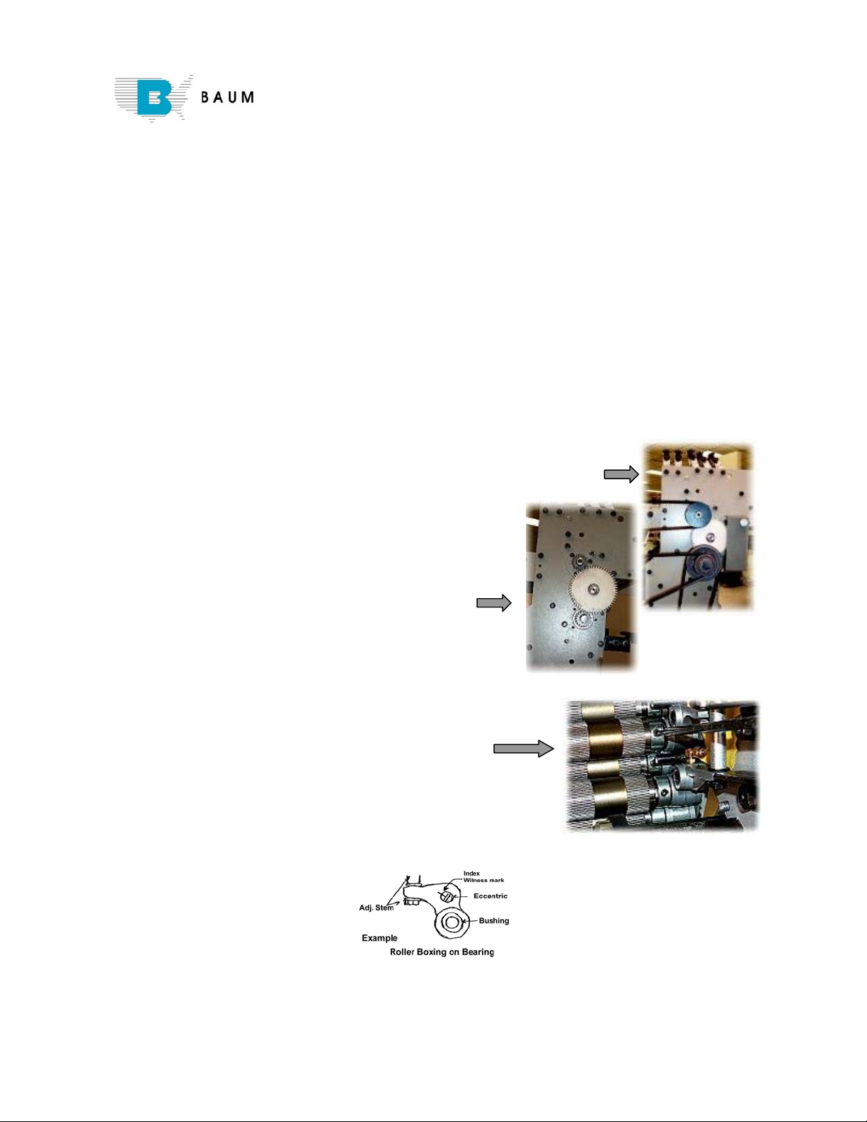
1. Set the protractor at five degrees,(the indicator
would be at 95 degrees.) Be sure the #1 and
main drive rolls are together by tightening the
adjustment knob until the washer under the roll
boxing is about 1/16
th
below the roll boxing at
all times during the adjustments.
2. Place the protractor on the end of the #1 and the
main drive roll as shown in Figure 1.
3. Refer to the notes as to the location of the
eccentric and start with the witness mark of the eccentric in that position. Rotate the
eccentric until the protractor bubble is five degrees in front of the main drive roll. Repeat
for the other end of the number one roll. Check both ends again to insure both ends are
the same, (five degrees.)
NOTE: Be sure the high point, (see Figure 2 below), of the eccentric is the same
direction on both sides. It is possible to get the same reading with the eccentric 180
degrees off, but the pivot point will be different.
Figure # 2
4. To set the end play in the number one roll, insert a ten thousands feeler gauge between
the collar on the roller and the roll boxing. Use a flat blade screw driver between the
other side of the collar and the body of the roller moving the roll toward the gear side of
the roll. Hold a very light pressure and tighten the set screw in the collar. You should be
able to move the feeler gauge in and out with slight drag. Separate the number one roll
and the main roll. Work the number one roll side ways and you should have very little
movement.
5. Take the end play out of the main drive roll without using the feeler gauge. It should not
have end play BUT allow the roll to turn free without a bind. Tighten the number one
roll against the main drive roll until the washer under the roll boxing has no tension but is
still in contact with the roll boxing.
6. Loosen the set screw in the tension adjusting
screw and loosen the tension on the spring on the
right and left roll boxing. Now tighten it until the
tension adjusting screw just begins to put pressure
on the spring, then turn it one and one half turns
on a adjust adjustment screw with course threads
or two turns on a adjustment screw with fine
threads. To test the tension, you can insert a fine
Section 1 - Page 5
Page 6

Section 1 - How to Rebuild a Baumfolder..... continued
blade screw driver between the number one roll and main drive roll on the bear bands,
noting the pressure when opening and the snap together as you remove it. It should be
about the same on both sides. Now the rolls and the roll gear should be aligned and turn
free using your fingers to turn the rolls without the number two roll in contact with the
main drive roll.
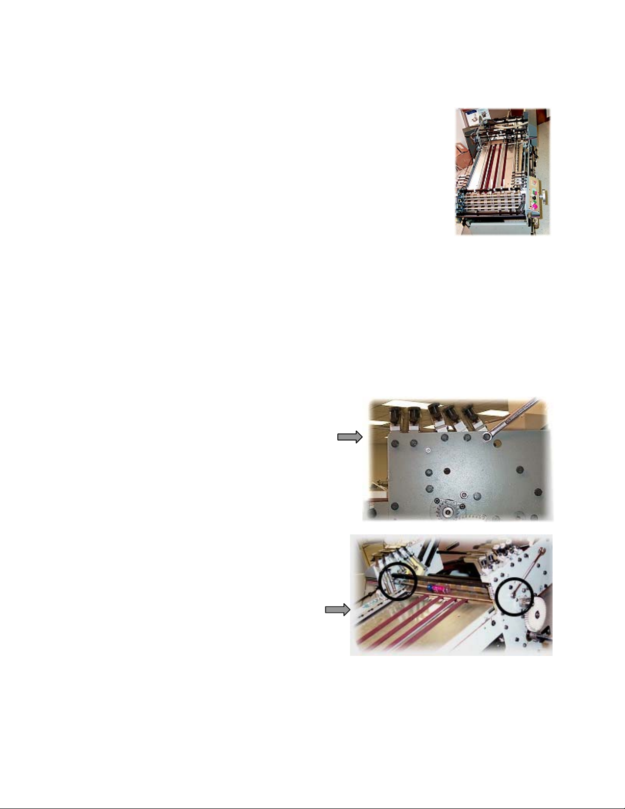
7. Now bring the number two roll into contact with the main drive by rotating the eccentric
on the right and left side to the approximant original position and tighten the roller
tension screw until the washer below the roll boxing is about 1/16
th
. below the roll
boxing. Watch to maintain this space while you are adjusting the roll or you could get a
false setting. Move the number three roll
away so it has no contact with the number
two roll. Insert the roll gage between the
one and two roll on the right side of the
roll as indicated in Figure 3. Turn the
right eccentric until there is a very light
tension on the gage block.( a tolerance of
up to + .003 of a inch as long as both
sides are the same.) Repeat the process on
the left side and check back and forth
until both ends are .718 of a inch. Set the
end play the same as you did with the
number one roll. Now loosen the tension
spring screw on both sides until the
number two roll falls away from the main drive roll with changing the tension screw
setting.(not allowing the tension screw to turn while loosing the spring tension.)now
tighten both right and left tension spring screw at the same time until the number two roll
just touches the main drive roll, then a complete one and one half turns on the course
thread adjustment screw or two complete turns on the fine thread adjustment screw.
Check the tension with the screw driver the same as you did on the first roll. The gear
side may feel slightly different due to the mash of the gears.
Figure 3
8. Repeat the same process with the number three roll as you did with number two roll, then
with number four and five roll the same as you did with number two roll.
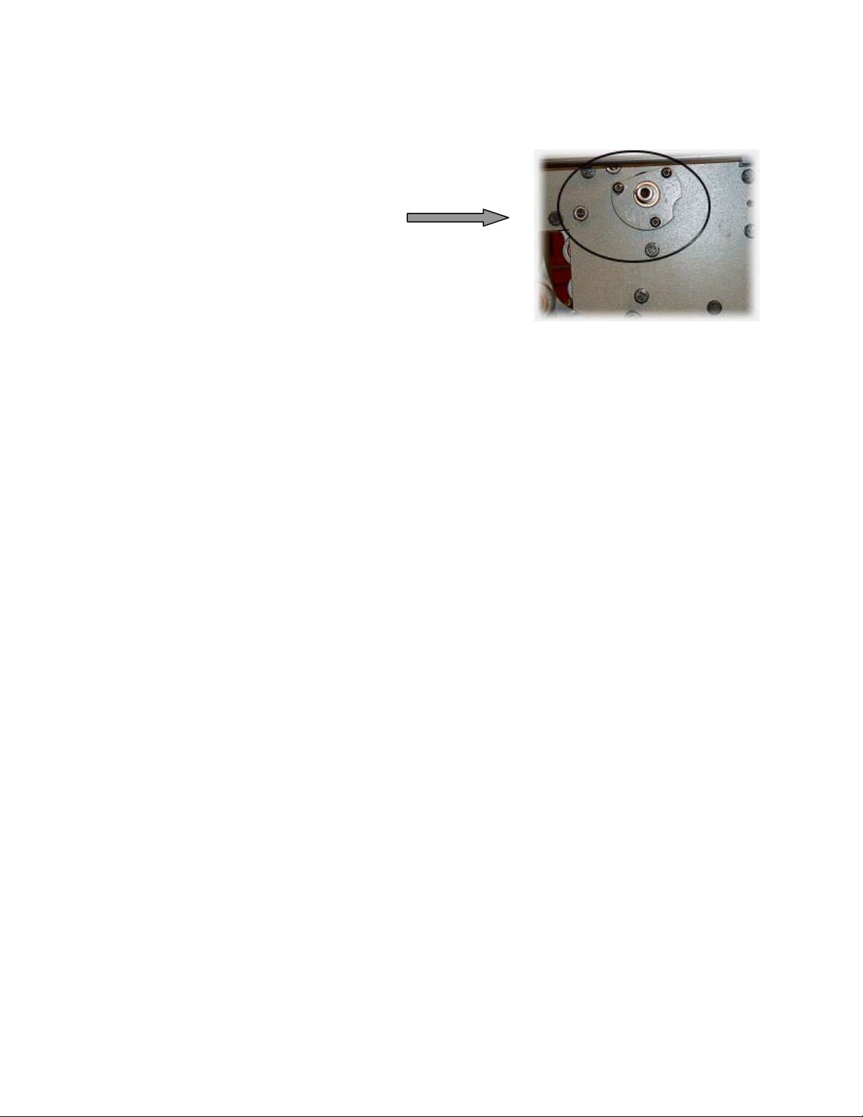
9. Now all of the rolls and roll gears should be in line. All
of the idler rolls, (all rolls except the main drive roll)
should have .010 of an inch end play. You should be
able to lay a straight edge from the number one roll
down across the number two roll and the number four
roll on the right and left ends and touch all three rolls.
You should also be able to turn the entire roll bank, (all
six rolls,) with your fingers.
10. See instructions on how to check fold plates and
deflectors to check or install the plates and/or
deflectors.
Section 1 - Page 6
Page 7

Section 1 - How to Rebuild a Baumfolder..... continued
11. Install the gears and belts on the non-operator side of the folder.
12. Replace the register table in reverse order that it was removed.
13. Replace ALL guards. Replace the slitter shaft. If you rebushed the slitter shaft boxings,
put the right and left boxing in place and line ream from left to right then right to left.
then install the slitter shafts, gears, and collars. If you have to line ream the slitter
boxings, do it BEFORE installing the guard.
14. Replace the hand wheel with a new free wheeling hand wheel.
15. Turn the folder over by hand several times to be sure nothing binds or rubs.
16. Square the side guide on the register with the number one roll.
17. Set all fold rolls, see section on calibrating baumsets and setting rollers.
18. Again turn folder over by hand and if every thing is free, apply power supply, turn folder
on and off to verify there is no electrical or mechanic problems and if not, run the folder
slow for a few minutes. Turn off the folder to see if there are any hot spots, Make SURE
power is turned off. If every thing is free, set up the folder and check for folder
accuracy.
NOTE: These instructions use the dimension 5° and .718 for some models of Baumfolders.
Other models use different dimensions – See the following section “Baumfolder and
O&M Gauges” for the proper dimensions for your folder.
Section 1 - Page 7
Page 8

ROLL GAUGE .718 Part Nbr 38334
PLATE GAUGE Part Nbr 91319
DEFLECTOR GAUGE
Part Nbr: For Parallel 10978
For 8 & 16 page 10613
FOLD PAN SETTINGS DEFLECTOR SETTINGS
PARALLEL
‘ A ‘
#1 Fold Pan .015 #1 Deflector .015
#2 Fold Pan .015 #2 Deflector .015
#3 Fold Pan .025 #3 Deflector .025
#4 Fold Pan .025 #4 Deflector .025
#1 Fold Pan .020 #1 Deflector .015
#2 Fold Pan .020 #2 Deflector .015
#3 Fold Pan .025 #3 Deflector .030
#4 Fold Pan .030 #4 Deflector .035
#1 Fold Pan .020 #1 Deflector .015
#2 Fold Pan .020 #2 Deflector .015
#3 Fold Pan .030 #3 Deflector .035
#4 Fold Pan .035 #4 Deflector .040
End play in Rolls .10
To ADJUST Fold Pans – Use Rail Ecc.
Front Ecc. - In & Out plus
Rear Ecc. - Up & Down only
‘ A ‘
8-PAGE
16-PAGE
Up & Down
Section 1 - Page 8
 Loading...