


BAUM
BAUM 2020
1ST STATION FOLDER W/PILE FEED
INSTRUCTION MANUAL
©Baumfolder Corp., 2006 |
Printed in U.S. . |
TP10243-5 |
|
PAGE 1 |
TP10243-5 |

©2006 BAUMFOLDERCORPORATION
All Rights Reserved
WARNING
•Do not operate this machine without all guarding in place.
•Do not make adjustments or perform maintenance on this machine with power on.
•Keep the machine and the work area clean and free of spills to prevent accidents.
•Be sure to replace any safety decals that may have been detached for any reason.
Baumfolder Corporation reserves the right to make changes in design or to make additions or improvements in its products without imposing any obligation upon itself to install them on its previously manufactured products. It is recommended that modifications to this equipment not be made without the advice and express written consent of Baumfolder Corporation.
FOLDER IDENTIFICATION
MODEL NO: _______________________________ SERIAL NO: _____________________________
SALES AGENCY: ____________________________________________________________________
INSTALLED BY: _____________________________________________ DATE: ________________
PHONE NO: _______________________________
TP10243-5 |
PAGE 2 |
|
|
CONTENTS |
|
DESCRIPTION |
PAGE |
||
I.) |
Safety .................................................................................................................................................................. |
|
6 |
II.) |
IntroductionOverview ............................................................................................................................... |
......... 7 |
|
III.) |
Transportation/Installation ................................................................................................................................ |
7 |
|
IV.) |
Squaring the Machine ........................................................................................................................................ |
7 |
|
V.) |
Electrical Connections ............................................................................................................................... |
........ 8 |
|
|
1.0 |
. Wiring the Pump (3 phase) ................................................................................................................... |
8 |
|
1.1. Wiring the Pump (1 phase)................................................................................................................................. |
8 |
|
|
1.2. Other Connections ............................................................................................................................... |
8 |
|
|
1.3 |
. Tapping the Transformer ...................................................................................................................... |
9 |
|
1.4 |
. Pump Connections ................................................................................................................................ |
9 |
VI.) |
"QUICK START" INSTRUCTION'S .............................................................................................................. |
10 |
|
VII.) |
Installing Fold Plates & Stacker Delivery ...................................................................................................... |
21 |
|
VIII.) |
Operator Controls ............................................................................................................................................ |
21 |
|
|
1.0 |
. Setting Folding Speed ......................................................................................................................... |
21 |
|
1.1 |
. Setting Stacker Belt Speed ................................................................................................................... |
21 |
|
1.2 |
. Emergency Stop Button ....................................................................................................................... |
21 |
|
1.0 Control Panel BAN-5 ................................................................................................................................ |
22 |
|
|
1.1 |
. Displays ............................................................................................................................................... |
22 |
|
1.2 |
. Machine Status Indicators .................................................................................................................. |
22 |
|
1.3 |
. Machine Control Pushbuttons ............................................................................................................ |
22 |
|
1.4 |
. Keypad Buttons with Selection Indicators .......................................................................................... |
23 |
|
1.5 |
. Keypad Buttons for Selection Adjustments ........................................................................................ |
23 |
|
2.0 RUN MODE FUNCTIONS ................................................................................................................................ |
23 |
|
|
2.1 |
. Machine Setup and Diagnostic Mode ................................................................................................. |
23 |
|
2.2 |
. Counter Setup Mode ........................................................................................................................... |
27 |
|
2.3 |
. Easy Mode and Continuous Cycle Mode ........................................................................................... |
28 |
|
2.4 |
. Learn Mode ......................................................................................................................................... |
28 |
|
2.5 |
. Make Ready Mode .............................................................................................................................. |
29 |
|
2.6 |
. Network Job Mode .............................................................................................................................. |
30 |
|
2.7 |
. Production Mode ................................................................................................................................ |
30 |
|
3.0 LOGIC BOARD STATUS INDICATORS ............................................................................................................. |
31 |
|
|
4.0 Process Variables Definitions .................................................................................................................. |
32 |
|
|
4.1 |
. Total Input Count ................................................................................................................................ |
32 |
|
4.2 |
. Total Output Count ............................................................................................................................. |
32 |
|
4.3 |
. Batch Down Count .............................................................................................................................. |
32 |
|
4.4 |
. Number of Batches .............................................................................................................................. |
32 |
|
4.5 |
. Current Rate ......................................................................................................................................... |
32 |
|
4.6 |
. Main Drive Run Time .......................................................................................................................... |
32 |
|
4.7 |
. Main Drive Velocity ............................................................................................................................. |
32 |
|
4.8 |
. Waste Count (DCT500) ....................................................................................................................... |
32 |
|
5.0 COUNTER SETUP VARIABLES ....................................................................................................................... |
32 |
|
|
5.1 |
. Batch Preset ......................................................................................................................................... |
32 |
|
5.2 |
. Batch Output Type .............................................................................................................................. |
32 |
|
5.3 |
. Batch Output Time .............................................................................................................................. |
33 |
|
5.4 |
. Sheet Length ....................................................................................................................................... |
33 |
|
5.5 |
. Gap Length .......................................................................................................................................... |
33 |
|
5.6 |
. Suction Length .................................................................................................................................... |
33 |
|
6.0 SYSTEM MESSAGES AND RUN MESSAGES ....................................................................................................... |
34 |
|
|
6.1 |
. Power-Up Fault Messages .................................................................................................................. |
34 |
|
6.2 |
. Run Time Fault Messages ................................................................................................................... |
35 |
|
6.3 |
. Machine Run Error Messages ............................................................................................................. |
36 |
PAGE 3 |
TP10243-5 |
|
|
|
CONTENTS |
|
DESCRIPTION |
PAGE |
|||
IX.) |
Pile Feeder Operation ...................................................................................................................................... |
37 |
||
|
|
1.0 |
. Loading ............................................................................................................................................... |
37 |
|
|
1.1 |
. Hold-down Locations .......................................................................................................................... |
37 |
|
|
1.2 |
. Air and Vacuum Setting ....................................................................................................................... |
37 |
|
|
1.3 |
. Front Blow Tube Settings .................................................................................................................... |
38 |
|
|
1.4 |
. Vacuum Wheel .................................................................................................................................... |
38 |
X.) |
Register Operation .......................................................................................................................................... |
39 |
||
|
|
1.0 |
. Double Sheet Detector ........................................................................................................................ |
39 |
XI.) |
BaumsetAdjustment ........................................................................................................................................ |
40 |
||
|
|
1.0 |
. Adjusting Folding Rollers ................................................................................................................... |
40 |
XII.) |
Setting Fold Plates ........................................................................................................................................... |
41 |
||
XIII.) |
Setting Deflectors ............................................................................................................................................ |
41 |
||
XIV.) |
Stacker Operation ........................................................................................................................................... |
42 |
||
XV.) |
Scoring/Slitting/Perforating ........................................................................................................................... |
43 |
||
|
|
1.0 |
. Slitter Shaft Removal ........................................................................................................................... |
43 |
|
|
1.1 |
. Scoring ................................................................................................................................................ |
44 |
|
|
1.2 |
. Perforating ........................................................................................................................................... |
45 |
|
|
1.3 |
. Slitting ................................................................................................................................................. |
46 |
|
|
1.4 |
. Trimming .............................................................................................................................................. |
47 |
|
|
1.5 |
. Trimming a Strip from Center of Sheet ................................................................................................. |
48 |
|
|
1.6 |
. Blade Installation ................................................................................................................................. |
48 |
XVI.) |
Lubrication/Maintenance ................................................................................................................................. |
50 |
||
XVII.) |
Technical Specifications .................................................................................................................................. |
51 |
||
XVIII.) |
Accessories ...................................................................................................................................................... |
51 |
||
XIX.) |
Troubleshooting ............................................................................................................................................... |
52 |
||
XX.) |
Operating Tips ................................................................................................................................................. |
54 |
||
XXI.) |
Principles of Mechanical Folding .................................................................................................................... |
56 |
||
XXII.) |
Jobsetupexample ............................................................................................................................................. |
57 |
||
XXIIi.) |
FoldingChart ................................................................................................................................................... |
61 |
||
XXIV.) |
Manual Usage ................................................................................................................................................... |
63 |
||
XXV.) |
Typical Layout & Sheet Orientation ................................................................................................................ |
64 |
||
XXVI.) |
Impositions ....................................................................................................................................................... |
65 |
||
|
#1 |
|
4 - PAGE ............................................................................................................................................... |
65 |
|
#2 |
|
4 - PAGE, DOUBLE IMPOSITION ........................................................................................................ |
65 |
|
#3 |
|
6 - PAGE, STANDARD ......................................................................................................................... |
65 |
|
#4 |
|
6 - PAGE,ACCORDION ....................................................................................................................... |
65 |
|
#5 |
|
8 - PAGE, PARALLEL IMPOSITION .................................................................................................... |
65 |
|
#6 |
|
8 - PAGE, RIGHTANGLE ..................................................................................................................... |
65 |
|
#7 |
|
8 - PAGE, RIGHTANGLE OBLONG ..................................................................................................... |
66 |
|
#8 |
|
8 - PAGE, RIGHTANGLE DOUBLE IMPOSITION ............................................................................... |
66 |
|
#9 |
|
8 - PAGE, PARALLELOVER & OVER .................................................................................................. |
66 |
|
#10 |
|
12 - PAGE BOOK, SADDLE STITCH ................................................................................................... |
66 |
|
#11 |
|
12 - PAGE BOOK, SADDLE STITCH ................................................................................................... |
66 |
|
#12 |
|
12 - PAGE LETTER FOLD, HEADS OUT ............................................................................................. |
66 |
|
#13 |
|
12 - PAGE LETTER FOLD, HEADS IN ................................................................................................. |
67 |
|
#14 |
|
12 - PAGE LETTER FOLD,ACCORDION ............................................................................................. |
67 |
|
#15 |
|
16 - PAGE, THREE RIGHTANGLE BOOK IMPOSITION .................................................................... |
67 |
|
#16 |
|
12 - PAGE FOLDER, HEADS OUT ....................................................................................................... |
67 |
|
#17 |
|
24 - PAGE BOOKLET ........................................................................................................................... |
67 |
|
#18 |
|
32 - PAGE BOOK .................................................................................................................................. |
67 |
XXVII.) |
Service |
............................................................................................................................................................ |
68 |
|
TP10243-5 |
PAGE 4 |
|
List of Tables |
DESCRIPTION |
PAGE |
Table 1. Machine Setup Parameter List "A" ........................................................................................................................ |
24 |
Table 2. Machine Monitor Parameter List ............................................................................................................................ |
24 |
Table 3. Machine Setup Parameter List "B" ......................................................................................................................... |
25 |
Table 4. Machine Diagnostic Parameter List ......................................................................................................................... |
26 |
Table 5. Future Features List ................................................................................................................................................ |
26 |
Table 6. Machine Usage Status Parameter List ..................................................................................................................... |
27 |
Table 7. Output Type Animations ........................................................................................................................................ |
27 |
Table 8. Count Source Selection ........................................................................................................................................... |
28 |
Table 9. Learn Mode Status ................................................................................................................................................. |
28 |
Table 10. Suction Mode Symbols ........................................................................................................................................ |
29 |
Table 11. Suction Length Function ....................................................................................................................................... |
29 |
Table 12. Determining the Large Display Contents ............................................................................................................... |
30 |
Table 13. Reset mode Selection ............................................................................................................................................. |
31 |
Table 14. LED Status Indicators ............................................................................................................................................ |
31 |
Table 15. Output Delay and Duration ................................................................................................................................... |
33 |
Table 16. Power Up Fault Messages ..................................................................................................................................... |
34 |
Table 17. Run Time Fault Messages ..................................................................................................................................... |
35 |
Table 18. Machine Run Error Messages ............................................................................................................................... |
36 |
PAGE 5 |
TP10243-5 |

SAFETY FIRST
Your new Baum paper folding machine has been designed in accordance with the latest safety specifications. The warning and caution labels on the machine must remain in place. Make sure all guarding provided is in place before starting up and running the machine.
Due to the nature of the work process of paper folding machines, there are parts and areas on the machine which cannot be completely covered without interfering with the operation of the machine. Therefore, sound personal work habits and strict observance of all safety precautions is required for the protection of the operator, co-workers, and the machine.
Be sure to follow these safety precautions:
1.Study the safety instructions at your plant and those provided in this manual.
2.Study the operating instructions carefully before operating the machine.
3.Make sure that your co-workers are familiar with the work process, potential danger areas,
and all necessary safety measures.
4.Make sure that the machine is in good working order before turning it on.
5.If the machine suddenly stops for whatever reason, do not restart it right away. Someone may have stopped the machine, but failed to press the emergency (Stop) button. If the machine is restarted unexpectedly, your co-worker could be seriously injured.
6.Always press the emergency (Stop) button first if you stop the machine for adjustments or maintenance work which must not be done while the machine is in operation.
7.For extensive maintenance or repair work, turn off the main power supply.
8.Never use improper or defective tools.
9.After making adjustments or after doing maintenance or repair work, always make sure that all tools and other objects are removed from the machine. Otherwise, they might fall into the machine, causing severe damage or injuries.
10.Make sure that all safety devices are in place before restarting the machine.
11.Never clean moving parts of the machine (rollers, shafts, etc.) or remove any test sheets or paper jams while the machine is running.
12.Keep the floor around the entire machine clean. Immediately clean up any oil, grease, or paint spills from the floor. Remove tools, cleaning cloths, and paper scraps from all work areas.
13.Never allow unauthorized personnel to make adjustments on the machine, remove problem sheets, or start the machine.
14.Never climb over the machine or crawl into it while it is turned on.
15.Immediately repair or replace any safety devices which have become ineffective or are missing.
16.Report any exposed cables or exposed electrical connections.
17.Always have a certified qualified electrician perform all electrical maintenance.
18.Do not make adjustments or perform maintenance with the power on.
19.Become familiar with and follow the safety labels on the next page. Replace any of these labels that are damaged or lost.
Additional Notes:
20.Do not attempt to remove a paper jam, no matter how minor it may appear to be, while the machine is running.
21.When cleaning the fold rolls, use the handwheel for turning. Be sure the power to the machine is off.
22.Turn off the machine before making any adjustments to the scoring, perforating, or slitting attachments. Keep hands and clothing away from the slitter shafts when the machine is running.
TP10243-5 |
PAGE 6 |
 - Instruction Manual")
INTRODUCTION OVERVIEW
The 1st station [parallel] folder with pile feeder contains the following main components (Figure 1):
1.Pile Feeder
2.Register
3.1st Station Folder (Parallel)
4.Fold Roller Gapsets
5.Fold Plates
6.Slitter Shafts (not shown)
7.Delivery (Stacker)
8.Operator Controls
9.Double Sheet Detector (Caliper)
10.Vacuum Pump (not shown)
11.Handwheel
Figure 1
Level the machine on the floor. Place a spirit level on the #2 fold roller (Figure 3) and on the feeder crossmembers.
SQUARING THE MACHINE
It is essential that this folding machine is square in order for it to work properly. To square the machine, measure diagonally across corners from feeder frame to folder frame (Figure 4). Dimensions shown are approximate. Be sure that the measurements taken are identical within 1/16-inch. If the machine is out of square, shift the frames in the direction needed until the proper squareness is obtained.
#2 FOLD ROLL
Figure3
TRANSPORTATION/INSTALLATION
As soon as you receive your new folder, and before removing the machine from the skid, check carefully for any damage to the shipments. If any damage is found, promptly contact your Baumfolder sales representative.
To lift the folder from the skid, place the fork lift rails under the lower rails as shown in Figure 2. Note that the fork lift must have at least a 1500 lb. capacity.
Remove all rust protection coating after unpacking the folder.
Figure2
Figure4
PAGE 7 |
TP10243-5 |

W2 U2 V2
|
|
|
|
GND |
#4 |
#5 |
U1 |
V1 |
W1 |
|
|
#1 |
#2 |
G/Y |
|
|
#3 |
W2 U2 V2
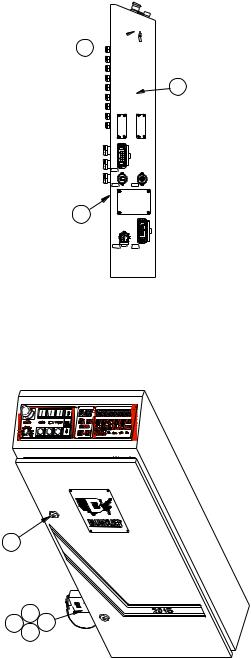
ELECTRICAL CONNECTIONS
1.0Wiring the Pump (2020 / 3 phase)
Connect the pressure/vacuum pump at the pump
junction box (Figure 5) using the attached cable. Follow the instructions to the left for the proper connections.
Turn the main power switch to the "ON" position. Switch the pump on momentarily and check for proper pump rotation as indicated by the rotation arrow on the pump. Immediately turn off the pump if the rotation is wrong.
If the rotation is incorrect interchange any two of the three wires #1, #2, or #3 in the pump motor terminal box.
|
|
|
GND |
#4 |
|
U1 |
V1 |
#3 |
W1 |
||
|
|
#1 |
G/Y |
|
|
#2 |
1.1Wiring the Pump (2020 / 1 phase)
Connect the pressure/vacuum pump at the pump
junction box (Figure 5) using the attached cable. Follow the instructions to the left for the proper connections.
Note: Dotted line indicates the cnange you need to make if the pump is running backwards
1PHASEONLY
Figure 5
1.2Other Connections
Refer to the serial number plate for electrical
requirements. The serial number plate notes the voltage, phase and hertz, minimum time delay fuse, total machine amperage, and minimum wire conductor size for the main power connection.
The main power is connected directly to the line side of the main power switch. In a (2020 / 1 phase) use L1 and L2 only. In a (2020 / 3 phase) use L1, L2, L3.
All electrical connections are to be made by a certified electrician. Refer to local building electrical codes for proper and safe connections.
For the following items, refer to Figure 6. Run a power cable from your distribution box to the main control box on the pile feeder. Turn the main power switch to zero. Using the appropriate tool, open the latches on the control box door and open the door.
NOTE: The door is connected to the main box by a ground wire that should not be removed.
TP10243-5 |
PAGE 8 |
1.3TappingtheTransformer
Pass the power cable through the strain relief and the
hole provided in the control box. Connect the power cable to the open terminals on the main disconnect in the control box. The incoming ground wire should be attached to the ground stud located in the lower right-hand corner of the control box.
To tap the transformer, read the incoming voltage at the main disconnect. Then move the wire numbered 7L2 on the transformer to the corresponding tap on the transformer.
Tighten all screw connections and close the door before switching the machine on.
A connector is provided for power connection to the stacker. The stacker must be plugged into the socket for the machine to operate, if not, install the blind plug attached to the box.
A connector is provided for power connection to the second station (8-page) fold unit. If no additional folding station is to be connected, the connector must be closed off with a blind plug.
1.4Pump Connections
Connect the air hoses to the pump. The small diameter
hose is connected to the vacuum side of the pump. Connect it to the barbed fitting above the ball valve on one end and the other end to the vacuum solenoid valve on the pile feeder.
Connect the larger diameter hose to the remaining outlet port on the pump and to the barbed fitting on the pile feeder at the end of the blow bar.
Troubleshooting tips and actions required for the display messages that may appear on the control readout may be found the "Diagnostic Messages" section of the manual.
3 
2
1X7 |
|
1X10 |
1X12 |
1
1X2 |
1X1 |
4
6
8 5
7
Figure 6
PAGE 9 |
TP10243-5 |

BAUMFOLDER 2000 Series “QUICK START” INSTRUCTIONS
TURNING THE MAIN SWITCH ON
When you turn on the Main Power Switch located on the side of the Control Box , you must let the Control automatically run a self-test. During the self-test DO NOT Press any buttons. Pressing of a button will cause an Error Message to appear in the Main Display. To CLEAR Message turn Power OFF at the Main Power Switch—WAIT
5 SECONDS, then turn Power back on.
1.Turn on Main Power Switch on left side of control enclosure. - Wait until control finishes self-test.
2. |
Load paper on Pile Feed Table. Press Pile up |
GREEN Button |
|
||
|
Pile will raise automatically to correct height. |
|
|
|
|
|
NOTE: To STOP Pile—Press RED |
Button |
|
|
|
3. |
To START Drive Motor & Pump—Press |
GREEN Button ABOVE the |
symbol. |
||
|
To STOP Drive Motor —Press RED Button BELOW the |
symbol or Press EMER- |
|||
|
GENCY STOP BUTTON |
|
|
|
|
RAISING AND LOWERING THE PILE FEEDER LIFT TABLE
1. After loading paper onto Pile Feeder Lift Table, Press the GREEN Button
This will raise the paper to the proper feeding height automatically. You can stop the Pile Feeder Lift Table by Pressing the RED Pile Feeder
STOP Button
2.
To lower the Pile Feeder Table, you must first Press the RED Pile Feeder
STOP Button
TP10243-5 |
PAGE 10 |
Then Press the GREEN Button to lower Pile Feed Table. The Table will lower and stop automatically in its lowest position.
STARTING PRODUCTION WITH THE BAUM 2020
1.To START the Folder Drive, Press the GREEN Button on the Control Panel
just ABOVE the |
symbol, this will Start the Folder Drive and the Pump will automatically |
come on. |
|
2.To STOP the Folder Drive, Press the RED Button on the Control Panel just BELOW the
 symbol or Press the RED EMERGENCY STOP Button on the Control Panel or on the Stacker Control Panel. The Folder Drive will STOP, The Pump may continue to run for about 7 seconds. If you want to stop the pump at the same time as the folder drive press the Drive STOP button twice within a 0.5 seconds.
The Pump circuit has a minimum ON time of 4 SECONDS. If the Pump is commanded OFF within 4 seconds after it is started, it will continue run for the duration of the 4 seconds and then shut OFF.
3.To Turn the Pump ON without the Folder Drive coming On, Press the GREEN Button ABOVE the  symbol
4.To Turn the Pump OFF, Press the RED Button BELOW  the symbol NOTE: the Pump will stay ON for at least 4 SECONDS before being able to shut off.
Easy Mode:
This mode is an automatic setup mode that sets the sheet gap to 1 inch and vacuum duration to 5 inches. Most jobs may be ran with this mode of operation. A Z-fold or a product with a window will require the Continuous Mode of operation. You can not change the sheet gap or vacuum duration settings manually using the Easy-Mode. Only the DCT500 mode or Continuous Cycle mode allows adjustment of these settings.
PAGE 11 |
TP10243-5 |

The Easy-Mode is used for folds that require half of the sheet length or less going into the foldplate. These folding applications normally operate with a 1.0 Inch sheet gap. If you are folding half of the sheet length or more into the foldplate you must have a greater gap.
TURN THE EASY-PARAMETER ON/OFF
1. Press the |
Machine Setup button found in the top row. |
2. .Press the Sheet Gap
+ or - Buttons until P20 appears in the sheet gap display.
3. Press the Batch Count + Button until P25 appears in the sheet gap
display. You will now see the word “EASY” in the counter display
Batch Count + Button until P25 appears in the sheet gap display. You will now see the word “EASY” in the counter display, see Figure E1.
Figure E1
TP10243-5 |
PAGE 12 |

4. Look to the right hand end of the counter display. If an “ 1 “ appears in the display the Easy-
Parameter is turned on. If an “ 0 “ is displayed, the Easy-Parameter is turned off, see Figure E1.
To turn the Easy-Parameter on or off, Press the  Plus (+) button for the batch
time delay setup. Pressing this button changes the “ 1 “ to an “ 0 “ and back. This button is found at the far right side of the top row, see Figure E1.
5. Press the |
Machine Setup button again in the top row to confirm and exit pro- |
gramming mode. |
|
SELECT EASY MODE
Pressing this button enables the selection of either the EASY mode or cYcL mode
+
Pressing these buttons will toggle between the EASY mode or cYcL mode. Set EASY in the large display. You will notice that the sheet gap display screen has (3) dashes when the
Easy Mode is on and a number when it is off.
Press the mode selection button |
again to exit mode selection. |
PAGE 13 |
TP10243-5 |

SELECT CONTINUOUS CYCLE MODE
It is recommended to use the continuous cycle mode when the job requires more than ½ of the sheet length to go in the #1 fold plate or if the product has a window that will be sensed as the trailing edge of the sheet.
The continuous cycle mode allows you to select the SHEET GAP, SHEET LENGTH and the SUCTION LENGTH.
Pressing this button enables the selection of either the EASY mode or cYcL mode
+
Pressing these buttons will toggle between the EASY mode or cYcL mode. Set cYcL in the large display (see figure E1).
SETTING THE SHEET GAP AND SHEET LENGTH
The small 3 digit display shows the current setting for the sheet gap. The number on the right hand side of the large display (1) represents the current sheet length. Set the sheet gap and sheet length for the current job.
SETTING THE SUCTION LENGTH
Use the + and – buttons under the 10 segment bar graph display to adjust the suction length. Each segment represents 5% of sheet length. If 10 segments are illuminated 50% of sheet length is selected. So, it is important that the sheet length is set properly for the current job.
Press the mode selection |
button again to exit mode selection. |
TP10243-5 |
PAGE 14 |

TO START FEEDING
1.Press the GREEN Button to START the Folder Drive and the Pump.
2. |
Press the GREEN Button ABOVE the |
symbol to START the Vacuum |
|
Solenoid. The Sucker Wheel will pull a sheet from the Feeder onto the Register. |
|
TO STOP FEEDING
1. Press the RED Button BELOW the  symbol. This will turn the Vacuum
Solenoid OFF. The Sucker Wheel will STOP pulling sheets—BUT the Folder Drive and
the Pump will stay ON.
NOTE: You can also STOP feeding by Pressing the
RED PILE FEEDER STOP |
BUTTON. |
CHANGE SPEED OF FOLDER DRIVE
To change the speed of the Folder Drive, just turn the Potentiometer Speed adjust Knob on the Main Control Panel 1 thru 10, 10 being maximum speed
MACHINE PARAMETERS
Pressin  Button allows access to the Machine Parameters. The Machine Parameters may be monitored, some changed and various options (kicker, pile re-load, etc.) enabled or disabled.
Navigation through the parameters is accomplished by using the following procedure:
1. |
Pressing |
and |
directly UNDER the 3 digit display will select |
|
the various Parameters Groups by count of tens. |
||
PAGE 15 |
TP10243-5 |

|
EXAMPLE: Hold the |
|
MINUS Button, this will automatically count back to P00 |
|
|
(group P0). Now by Pressing the |
Button will take you to the next |
||
|
Parameter Group P10 – P20 - P30 – P40 – P50 – P60 |
|||
2. |
Pressing |
and |
directly UNDER the left 3 digits of the Large 8 digit |
|
|
display, this will select the individual Parameters in a select group. |
|||
EXAMPLE: Start with the first Group of Parameters, the 3 digit
display reads P00. Pressing the |
this will take you to Parameters |
P01 – P02 – P03 – P04 – P05 |
|
- To go to the next Group of Parameters Press 
The display will show P10. Pressing the button 
will take you to Parameters P11 – P12 –P13 – P14 (continue this sequence to move thru the rest
of the Parameter Groups P20 – P30 – P40 – P50 – P60
3. To change one of the machines Parameter Settings Press |
or |
Buttons UNDER the right most 2 digits of the large 8 digit display. |
|
The following is a list of the available parameters. Please see the Operators Manual for a definition of each parameter.
TP10243-5 |
PAGE 16 |

PAGE 17 |
TP10243-5 |

To get out of the Machine Parameter Settings Mode, Press |
again. The displays will |
return to normal operations. |
|
BATCH COUNTING SETUP
To enter Batch Count Set-Up, Press
1.This will bring up 3 display functions on the Control Panel.
First is the Small 3 digit display – this display must show |
ood |
|
|||||
|
|
||||||
If the display shows any other Mode, the Batch Counter |
|
|
|
||||
will not function. To change, Press the |
|
or |
|
Buttons directly |
|||
UNDER the 3 digit display to change this Mode of Operation. |
|||||||
|
|
|
|
|
|
|
|
NOTE: If the display shows |
ooo |
or |
oo o |
|
the wrong batching device is |
||
|
|
|
|||||
selected. These batching devices are Options not sold as standard equipment.
2.In the Large 8 digit display you will see 2 display functions.
1 |
|
2 |
1.Is the number of sheets in the batch.
2.Is the time delay between batches.
A.In the first 3 digits of the 8 digit display, this is the number of Sheets in each batch.
To adjust the number, press the |
or |
Button directly UNDER |
the display until the desired number is displayed. |
|
|
B.In the last 2 digits of the 8 digit display, is the time between batches setting. This setting moves in Tenth (10th) of Seconds, to adjust, Press
TP10243-5 |
PAGE 18 |

the  or
or  Buttons directly UNDER the 2 digit display until the desired delay number is displayed.
EXAMPLE:
This is set-up for 10 pieces in a Batch with a 1.5 second delay between Batches.
3. |
To return back to RUN mode, Press |
Button and set either the Batch Size or |
|
Time Delay to Zero and the Folder will run continuously. |
|
STOP FEED
In Batch Count Mode, you also can have the Feeder Set-Up for a Stop Feed Count. You can enter the number of Sheets that you wish to Feed and the Feeder will Feed that number and STOP. The feeder will not Re-Start until you Press SHEET START Button.
1. |
Press the |
Button on the Control Panel, the 3 display functions on the |
|
Control Panel will appear. |
|
A.In the first 3 digits of the 8 digit display enter the Number of
Sheets that you wish the Feeder to Feed by Pressing either 
or Buttons.
B.In the Last 2 digits of the 8 digit display, Press and HOLD
the  Button until the LETTERS
  appears – the machine will now Feed only the Number of Sheets that you have entered.
EXAMPLE:
With this setting the Feeder will run 10 sheets and Stop Feeding.
PAGE 19 |
TP10243-5 |

RESETTING THE TOTAL COUNTER
To reset the Total Counter, Press Button |
; ensure the red LED is illuminated. |
|
Press Button |
and HOLD DOWN for 3 SECONDS, |
|
The Large 8 digit display will begin to Count BACKWARDS from 5.4.3.2.1, then display CLEARED, the Counter is then ZERO.
You MUST Press and HOLD Button |
as the display is counting |
BACKWARDS, if at anytime the |
ZERO Button is released, the Counter will |
display the Last Count Value |
|
NOTE The Batch counte r will also be reset to 0 by this procedure.
RESETTING THE BATCH COUNTER
Press the Batch counter Button |
; ensure the red LED is illuminated. |
|
Press Button |
and HOLD DOWN for 3 SECONDS, |
|
The Large 8 digit display will begin to Count BACKWARDS from 5.4.3.2.1, then display CLEARED, the Counter is then ZERO.
NOTE The Total counter will not be reset to zero.
TURN OFF BATCH COUNTING:
Press the |
counter setup button and set either the batch size or time dwell to zero. |
Exit the counter setup mode by pressing the counter setup button again or any button in the second row.
TP10243-5 |
PAGE 20 |
INSTALLING FOLD PLATES & STACKER DELIVERY
Install the fold plates into the folder. When installing the fold plates, take note of the symbol on the fold plate stop (Figure 7-1). The swing deflector may only be brought forward when the deflector symbol is also in the forward position. Lock the fold plates in position with the clamp levers (7-2). See "Fold Pan" section for fold plate setting procedure.
Attach the delivery stacker (3-2) by hooking the hanger brackets onto the round rods at the exit end of the folder. Plug the stacker power cable into the corresponding outlet on the main control enclosure on the pile feeder (Figure 6- 1).
Pull the handwheel (Figure 1-11) to manually turn the fold rollers to be sure that they are operating smoothly. Check for any foreign material, and be sure that the deflectors do not touch the fold rollers.
1
2
Figure 7
1
OPERATOR CONTROLS
The main operator control panel (Figure 8) is located at the pile feeder. See the "Control Panel" section for a detailed description of all the buttons.
1.0Setting Folding Speed
The speed of the fold rollers may be set while the folder
is running! This is done by adjusting the speed control potentiometer located on the top left side of the main control panel. Clockwise rotation speeds the folder up; counterclockwise rotation slows the folder down.
1.1Setting Stacker Belt Speed
An infinite speed range between high and low is set by
turning the control knob (Figure 9-1).
1.2Emergency Stop Button
When an emergency stop button (8-1 & 9-2) is pressed,
the result is:
Sheet feed - stop Folder drive - stop Pile lift - stop
The pressure/vacuum pump continues to operate. The emergency stop button must be pulled to release before the machine can be restarted. An error message "StoP" will appear on the readout.
The emergency stop buttons are found at the main operator control panel (8-1) and the delivery control (9-2).
2 1
Figure 9
4 |
5 |
6 |
7 |
3 |
|
|
8 |
2 |
|
|
9 |
1 |
|
|
10 |
+ |
+ |
+ |

 h
h 

 0
0
+
Figure 8
PAGE 21 |
TP10243-5 |
 Loading...