

Page 1
BAUMFOLDER
CORPORATION
Quality Bindery Equipment Since 1917
ND5 DRILL
INSTRUCTION & PARTS
MANUAL
©Baumfolder Corp., 2000 Printed in U.S.A TP10354
1 TP10354
Page 2

© BAUMFOLDER CORPORATION 2000
All Rights Reserved
WARNING
• Do not operate this machine without all guarding in place.
• Do not make adjustments or perform maintenance on this machine with power on.
• Keep the machine and the work area clean and free of spills to prevent accidents.
• Be sure to replace any safety decals that may have been detached for any reason.
Baumfolder reserves the right to make changes in design or to make additions or
improvements in its products without imposing any obligation upon itself to install them on
its products previously manufactured. It is recommended that modifications to this
equipment not be made without the advice and express written consent of Baumfolder.
TP10354 2
Page 3

Contents
FUNDAMENTAL SAFETY ................................................................................................................ 4
INSTRUCTIONS ................................................................................................................................ 4
SECTION 1:
MAIN ASSEMBLIES ............................................................................................................... 1-1
1 PHASE ................................................................................................................................................................. 2
3 PHASE ................................................................................................................................................................. 8
3 PHASE WITH MOVEABLE TABLE ...................................................................................................................14
SECTION 2:
BASE & ENCLOSURE ASSENBLY........................................................................................ 2-1
PAPER DRILL BASE ASSEMBLY ........................................................................................................................... 2
ENCLOSURE COVER ASSEMBLY .......................................................................................................................... 7
SUPPORT BAR & SHAFT ASSEMBLY .................................................................................................................. 9
LOWER SPRING GUIDE ASSEMBLY ....................................................................................................................11
SECTION 3:
HYDRAULIC ASSEMBLY ....................................................................................................... 3-1
1 PHASE HYDRAULIC ASSEMBLY ....................................................................................................................... 2
1 PHASE HYDRAULIC ASSEMBLY ....................................................................................................................... 2
HYDRAULIC DIAGRAM ....................................................................................................................................... 8
SECTION 4:
DRILL & MOTOR ASSEMBLY ............................................................................................. 4-1
1 PHASE DRILL & MOTOR ASSEMBLY ............................................................................................................... 2
1 PHASE ELECTRICAL ASSEMBLY ...................................................................................................................... 8
1 PHASE SCHEMATIC .......................................................................................................................................... 11
3 PHASE DRILL & MOTOR ASSEMBLY .............................................................................................................. 12
3 PHASE ELECTRICAL ASSEMBLY ..................................................................................................................... 18
3 PHASE SCHEMATIC .......................................................................................................................................... 21
DRILL ASSEMBLY ................................................................................................................................................ 22
SECTION 5:
MOVEABLE & STATIONARY TABLES ................................................................................ 5-1
STATIONARY TABLE ASSEMBLY ........................................................................................................................ 2
MOVEABLE TABLE ASSEMBLY ........................................................................................................................... 6
SECTION 6:
ACCESSORIES ......................................................................................................................... 6-1
DRILL SHARPENER ASSEMBLY ........................................................................................................................... 2
SECTION 7:
LABELS ..................................................................................................................................... 7-1
LABELS .................................................................................................................................................................. 2
3 TP10354
Page 4

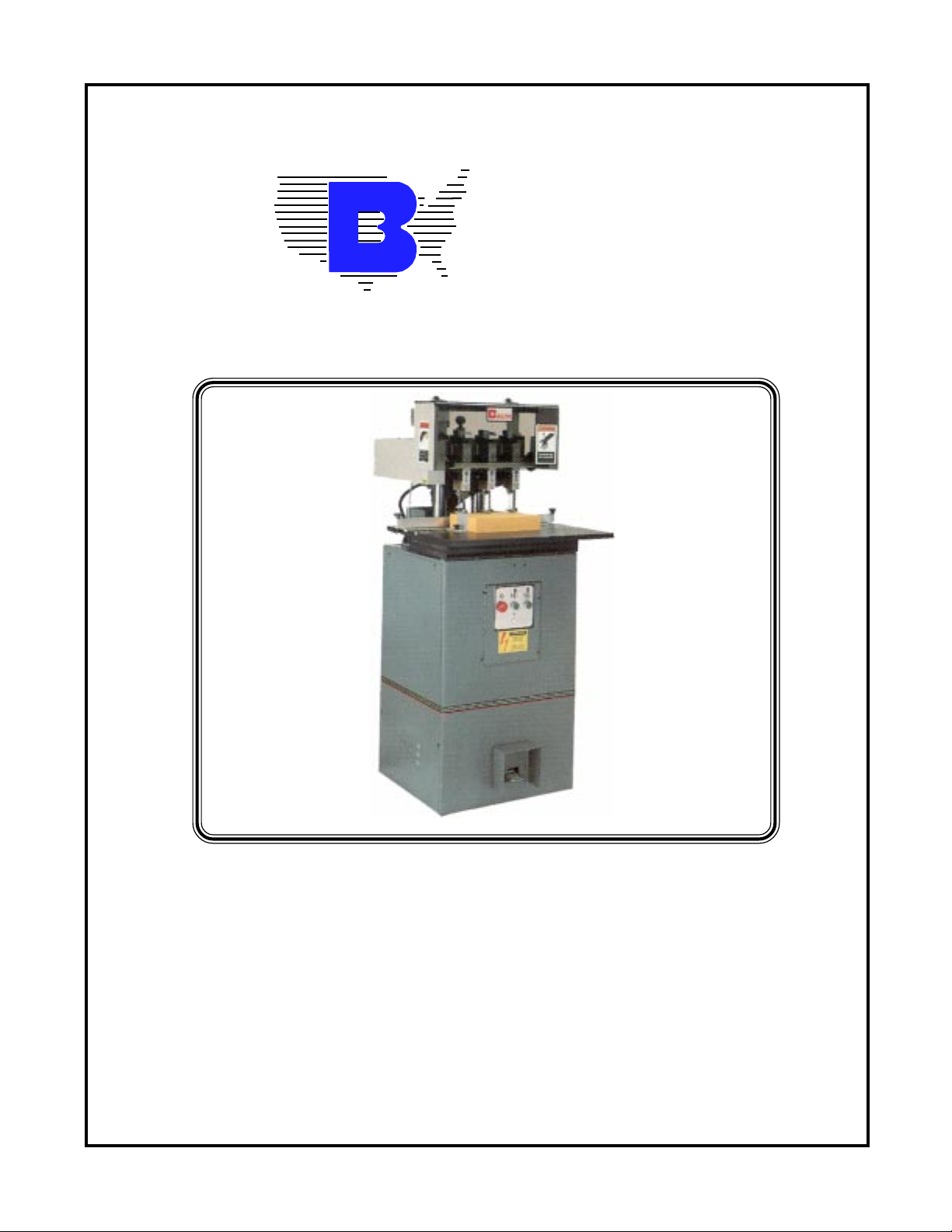
ND-5 PAPER DRILL
Your new ND-5 Paper Drill has been designed to provide you
with years of useful service, provided it is installed, maintained and operated according to the instructions contained
in this manual.
The ND-5 Paper Drill has the capability for five drill heads,
and is available with either a stationary (ST) or moveable
(MT) table. Dill bits are available in sizes ranging from 1/8
to 1/2 in diameter.
SAFETY INSTRUCTIONS
All guards, warning labels, lubrication and caution tags were
placed on this machine for your safety. Take time to become
familiar with all of them. These items must not be removed
from this machine.
The operation and maintenance of this machine should be
clearly understood. Besides exercising standard safety practices, operators, maintenance personnel and any other personnel involved with this drill, should be specifically instructed
on proper maintenance and safe operation of this machine.
All safety mechanisms are provided for your protection and
must not be altered.
Carefully remove the wood frame and remove one of the side
covers to find these items. Be sure to check off the parts received against the packing list. Examine the machine carefully
for any physical signs of shipping damage.
The machine is fastened to the skid with four bolts. Remove
these bolts and then carefully position the machine on the, floor.
Level the machine to prevent rocking during operation.
BACK GAGE INSTALLATION
Place the back gage bar at the rear of the table top. Insert the two
clamp knobs through the clearance holes provided in the bar.
Screw the clamps onto the bottom of the threaded rod that extends from the clamp knobs. Place the two back gage blocks on
the bar so that the thumbscrews are pointing toward the rear of
the machine. Set the bar using the scales on the right and left
sides of the table.
SIDE GAGE INSTALLATION
Slide the side gage assembly into the T-slot provided in the
table top. Slide the side gage to a location desired on the table
scale and tighten the knob by hand.
WARNING
Do not operate this machine without all
guards in place.
Do not make any adjustments or perform any maintenance on this machine with power on.
Keep the machine and the work area clean and free
of spills, to prevent accidents.
Be certain to replace any safety decals that may
have been detached for any reason.
INSTALLATION INSTRUCTIONS
This machine is shipped inside a protective wood frame. The
following parts are packaged inside the machine at the factory:
Waste Can Wood Blocks
Back gage Bar Drill Sharpener
Back gage Blocks Side Gage
Tools Instruction Manual
WASTE CAN INSTALLATION
Hang the waste can on the two shoulder screws at the top of the
rear of the machine base.
T00LS
A convenient accessories drawer has been provided on the
rear right hand corner of the machine base. A removable tray
is furnished for storing drill bits in a bath of lubricant while
they are not in use. All other tools can be placed in the other
compartment for quick, convenient access.
HYDRAULIC SYSTEM
Checking the hydraulic oil level in the reservoir is done by removing the right hand side cover and removing the four screws
that fasten the lid to the reservoir. The return line hose may
remain connected. The oil level must be just below the port
located near the top on the side of the reservoir. Do not fill
above this port!
TP10354 4
Page 5

ELECTRICAL SYSTEM
SETTING DRILL HEADS
Check the black serial number tag on the left rear corner of the
machine base for voltage/phase/hertz and amperage required.
This tag also lists the time delay fuse amperage and the wire
size for the supply conductor.
Check the proper rotation of the drill head drive shaft. The
rotation must be the same as indicated by the arrow decal
located on the side of the belt guard on the left hand side of
the machine. If the shaft is turning in the opposite direction,
change two of the wires in the incoming power cable of the
machine, choosing from the red, black and/or white wires. If
the drill head shaft is rotating in the opposite direction of the
arrow, the hydraulic system will not be able to create any
pressure.
STARTING
Two electric motors provide the power for this machine; one is
for the hydraulic power system and the other is for the spindle.
The electric motor for the hydraulic system drives a hydraulic
pump that creates the force to push the drill heads down. The
spindle motor drives the drill head spindles through a set of
belts and pulleys.
A) Raise the hinged top cover.
B) Insert the drill bits into the drill head spindles. Use drill extensions on all bits that have a threaded hole in the top end.
C) Make sure that the retainer on the spindle is down over the
horseshoe lock washer.
D) Move the drill heads to the desired locations by loosening
the clamp screws, then move to the left or right of zero on the
scale in front of the drill heads. The line that extends down from
the diamond logo on the cover plate is to be used to line up with
the graduations on the scale. Then lock the drill heads in place.
E) Adjust the spindles to their uppermost position by loosening
the set-screw located in the front of the drill head in the clamp
block at the top. Turn the knurled caps on top of the drill heads
in a counterclockwise direction until they are at their uppermost
position.
F) Turn on the hydraulic power system by pressing the green
pushbutton that is below the symbol showing a drill bit with a
vertical double arrow. DO NOT TURN ON THE SPINDLE MO-
TOR.
The two motors are started separately by pushing the corresponding start button indicated by the appropriate symbols on
the pushbutton panel. This feature is needed for setting drill
bits, for round cornering and slotting. This allows the hydraulic
system to be running while the spindle is not.
Both motors are turned off by a red mushroom stop pushbutton
located on the left side of the panel. This is a safety feature that
stops the entire machine.
WARNING
This machine is equipped with a safety interlock system which
prevents the spindle motor from being started when the hinged
top cover is raised, and automatically turns the spindle motor
off if the cover is raised after the spindle motor is turned on.
This safety feature is provided to prevent accidental contact
with moving parts. This feature must not be altered or tampered
with.
OPERATION
A maximum of five drilling heads can be used on this machine
with 1/4" drill bits and smaller. A maximum of four drill heads
with 3/8" drill bits and a maximum of three drill heads with
1/2" drill bits.
G) Depress the foot pedal and hold it down. The drill heads will
come down. Adjust all drill heads individually by turning the
knurled knob on top of the drill heads clockwise until they just
cut through a single piece of 20lb paper.
H) Remove your foot from the foot pedal and the drill heads will
come back up. Tighten the set-screw in the drill heads as referred
to in step (E). CAUTION: Do not over-tighten. To lock more than
finger tight is unnecessary and will cause damage to the threads
on the spindle sleeve.
I) Lower the hinged cover before turning the spindles on.
MOVEABLE TABLE INSTRUCTIONS
The moveable table is a unique feature that allows the operator
to drill several holes without moving the stock by hand. Every
MT paper drill is equipped with an adjustable step bar that has
five adjustable stops. The moveable table can become a stationary table by using the table lock plunger located in the front of
the machine under the table.
NOTE: Use drill extensions on all drill bits that have a
threaded hole in the top of the drill bit.
5 TP10354
Page 6

OPERATION
A) It is best when setting up a job to begin with the table locked in its
center position and work outward from the zero mark on the scales. The
zero marks on the drill head scale, table scale, and step bar scale, are all
in line when the table is locked in the center position. To lock the table in
the center position, turn the knob under the front of the table so that it
will slide the plunger up into the hole provided in the tie bar when the
hole passes over the plunger.
B) The five table stops are located in the front of the machine underneath the table top. The stops are set by aligning the indicator at the top
of each stop with the scale located behind them. The stops are moved
by loosening the set screws in the stops and sliding them to their desired location. Once the stops have been located and tightened in position, you may release the table from the locked position by pulling the
knob below the table down and giving it a quarter turn.
C) After the table is unlocked from the center position, you will see that
the table will move to the left and stop when it comes to the closest stop
on the adjustable step bar. To move on to the next stop, simply pull up
on the flat black handle on the left hand side of the table, and drop it
back down so the next stop will be found.
D) If you have an indexing job that you do quite often, optional special
pre-cut step bars are available. Installation of a pre-cut step bar is quite
simple. Remove the adjustable step bar by removing the two socket
head cap screws and spacers. Mount the pre-cut step bar in the same
place, using the same two socket head cap screws, the two spacers
are.not needed. Adjust the latch plunger that is directly below the pre-cut
bar so that the teeth in the bar make contact with the beveled plunger. A
24mm open end wrench is required to loosen the plunger assembly.
Simply turn the assembly until the proper height is made and
retighten the nut.
F) Insert the cutting tool required in the square hole
at the bottom of the head. Make sure that the tool is
adjusted all the way up. This is done by loosening
the four socket head cap screws on the front of the
head and raising the knurled head screws. Push the
tool up as far as it will go and tighten the four socket
head cap screws just enough to hold the knife in
place.
G) Remove the waste chute from the machine. This is
done by removing the shoulder screw on the right
side of the support rail casting and sliding the left
mounting tab off of the roll pin on the left hand side
of the support rail casting.
H) Mount the right hand support bracket back on the
drill head support rail and drill head drive shaft. Replace the scale and fasten it to the bracket as it was
before. Tighten the hex head screw on top of the
bracket. Mount the hand knob back onto the end of
the drill head shaft and tighten the set screw against
the bottom of the key way.
I) Turn on the hydraulic power system and bring the
head down. Using the knurled head screw, adjust the
cutting tool down to the wood block. Do not turn on
the spindle motor. It is not needed at any time during
round cornering and/or slotting. The cutting tool
should be adjusted so that it makes a slight impression on the wood block.
J) Lock the cutting tool securely by tightening the
four socket head cap screws. Lightly tighten the set
screw on the right side of the slotting head to secure
the knurled head screw in place.
ROUND CORNERING AND SLOTTING INSTRUCTIONS
A) Raise hinged top cover.
B) Remove the hand wheel on the right hand side of the drill head drive
shaft by loosening the set screw in the hub of the knob and sliding it off
the shaft.
C) Remove the right hand drill shaft bracket by loosening the hex head
screws on the top of the right hand drill shaft bracket. Remove the
button head screw that holds the scale to the bracket. Slide the bracket
off the right end of the drill head drive shaft.
D) Remove, all drill heads.
E) Slide the round cornering /slotting head on the shaft and the drill head
support rail to the desired position and lock in place.
TP10354 6
K) Either remove or slide the standard side gage to
the right or left end of the table top.
L) Fasten the mounting block and cornering guide
together. Mount the assembly to the back gage bar
as shown in Figure 1, using the existing back gage
blocks as supports at each end.
Page 7

M) Use the impression in the wood block to set the corner
guide. Use the back gage bar clamps to adjust the guide
knob shown in Figure 1 to make slight adjustments to the left
or right.
ADJ. KNOB
BACK GAGE BAR
BACK GAGE BLOCK
ROUND CORNERING GUIDE
MOUNTING BLOCK
WOOD BLOCKS
ROUND CORNER &
SLOTTING GUIDE
FIGURE 1 ROUND CORNER AND SLOTTING GUIDE
IMPORTANT NOTES
1. For best results and to avoid knife breakage, no more than
1/2 inch of paper should be cut at any one time.
2. Turn the machine off when making adjustments.
3. Replace any guards that were removed before you use the
machine.
7 TP10354
T ABLE T OP
Page 8

DRILL HEAD AND BIT TIPS
7. USE DRILL EXTENSIONS
1. KEEP DRILLS SHARPENED
A dull drill bit can be a major cause of drill bit breakage. Sharpening and cleanliness help prolong bit life. Imperfections in
drilling indicate dull drills. A dirty drill bit will clog and will
cause pressure build up that can split or break the drill bit.
Clean the drill bits of all chips after each use and apply a light
film of oil to the inside and outside. When drilling coated stock,
the chips frequently are compacted into slugs inside the drill
bit, it is important that the drills be cleaned out immediately
before the drill cools or the slugs will become a solid mass that
will cause the drills to break the next time they are used.
2. LUBRICATE DRILLS
Use the drill lubricant sticks that are provided with your drill to
assure better chip passage and to avoid overheating of the
drills. Touch the side of the drill bit near the cutting edge with
the end of the lubricant stick. Try to coat the inside of the bit as
well. Squeaking, slight burning or smoking is a common sign
that lubrication is needed.
3. SET THE DRILLS CORRECTLY
Do not cut too deeply into the wood blocks. The drills should
just touch the block enough to make an impression and cleanly
drill through the bottom sheet. Do not set the drills deeper into
the blocks after drilling, move the blocks or flip them over or
turn them end for end to get a new cutting surface. The use of
chipboard (cardboard) below the lift when drilling can sometimes improve the hole quality.
Drill extensions help chips flow up into the spindle and out of
the ejection slot. There are two sizes of extensions: the black
extension fits 1/8" through 5/32" drills; the gray extensions fit
3/16, 7/32, and 1/4" drills. The larger diameter drills do not
need extensions. Extensions help prevent drill breakage, especially when drilling coated stock.
8. PEMOVE DRILLS FROM HEADS WHEN FINISHED
Depending upon atmospheric conditions, if the drills are left in
the spindles overnight or for the weekend, they may rust. If this
occurs, they will be extremely difficult to remove.
9. LUBRICATE HEADS
A) Drill heads should be greased approximately once every
five working days with Lubriplate #1200-2 General Purpose
Grease or equivalent. Use only two squeezes of a small grease
gun. The grease zerk for the drill heads is located on the rear of
the head. To grease the heads, drop the waste chute out of the
way by removing the shoulder screw on the right side of the
support rail casting and slide the waste chute off of the roll pin
on the left side.
B) Put three to four drops of light oil in the top of each drill
head spindle once every four working hours, and once every
time before the drill is started. Use Marvel No. 005 Lubricating oil or equivalent.
4. CHECK BELTS
Loose belts can slip and cause overheating of drills. Tighten if
necessary, but be careful not to over tighten.
5. CHECK FOR RUNOUT OR WOBBLE
Drill head spindles that are worn or bent as a result of misadjustment can cause drill breakage. Have the spindles
replaced immediately.
6. INSPECT DRILL SHARPENER
Check the cutting edges of the carbide cutting tool for nicks
and sharpness. Dont let the drill drop on the cutting tool or the
cutting edge will be damaged on the tool. Use gentle pressure
when sharpening. Too much pressure will spread the mouth of
the drill, causing breakage. only a few turns will sharpen the
drill.
TP10354 8
Page 9

SPECIFICATIONS
DRILLING:
ELECTRICAL:
Motors: 1 hp pump
2 hp spindle
Available in:208-22OV/1 phase/60 hz at 20 amps
208-22OV/3 phase/60 hz at 10 amps
Electrical safety interlock that prevents spindles from rotating
when hinged cover is raised.
Separate start pushbuttons for the spindle drive motor and
the hydraulic power unit.
One stop button turns off the entire machine.
Indicator light is provided that tells the operator when a.
motor is overloaded.
Motor contactors have automatic reset feature.
Front cover is hinged for quick and easy access.
HYRAULIC:
1 1/2 qprn pump at 1800 rpm
1 gallon reservoir
Maximum number of drilling heads: 5
Drill bit sizes available: 1/8" to 1/2"
Max drilling capacity: 5 heads with 1/4 drill bits - 2 max.
4 heads with 3/8" drill bits - 2" max.
3 heads with 1/2" drill bits - 2" max.
Vertical drill bit adjustment in drill heads: 5/16"
Maximum center to center distance of heads: 10"
Minimum center to center distance of heads: 1.5"
Maximum distance from center of drill to back gage: 5.83"
Maximum distance between holes (MT): 23.13"
Min. distance between holes (MT): Adjustable stops: .38"
Fixed gages: .25"
Floor space required for ST drill: 36" x 26"
Floor space required for MT drill: 36" x 49.5"
Machine height: 59"
Shipping weight (approximate): 850 lbs.
Preset relief valve protects system
0il: Anti-wear hydraulic oil
Mobil DTE 24
Mobil DTE 25
Mobil DTE 26
Energol HLP-32
Energol HLP-46
MAINTENANCE CHECK LIST
Daily: 1. Sharpen drill bits
2. Lubricate drill bits
3. Lubricate drill head spindles
Weekly: 1. Grease drill heads
Monthly: 1. Check hydraulic reservoir oil level
2. Check drive tightness
Yearly: 1. Change hydraulic reservoir oil
ROUND CORNERING & SLOTTING:
Maximum lift height: 1/2"
Round corner cutters available: 3/16"r., 3/8"r., 1/2r.
Slotting cutters available: 30, 45, 60, straight slit
VALUE ADDED STANDARD FEATURES:
Hand drill sharpener and sharpening stone
Tool and accessories drawer with removable tray
Tools for removing heads from machine
Drill Ease drill bit lubricant sticks
Enclosed waste chute eliminates excessive chips on the floor
Large capacity, and easily removable waste can
Safety interlock hinged cover stops rotation when cover is
up
9 TP10354
Page 10

SHAPES OF ROUND CORNERS
SLOTTED HOLES PRODUCED
ACTUAL DRILL SIZES
DIAMETER: INCHES/(METRIC)
1/8" 5/32" 3/32" 7/32" 1/4" 9/32" 5/16" 11/32"
3-1mm 4mm 5mm 5-5mm 6mm 7mm 8mm 9mm 9-
CAPACITY: INCHES/(METRIC)
1" 1-1/8" 1-1/2" 1-3/4" 2" 2" 2" 2"
25mm 25mm 35mm 40mm 50mm 50mm 50mm 50mm 50mm 50mm
3/16" R
(5mm)
3/8" R
(9-5mm)
1/2" R
(12-5mm)
45 DEG
Drill bits, corner shaping cutters and slotted hole cutters are
available through Baumfolder or your local Baumfolder dealer.
TP10354 10
Page 11

TROUBLESHOOTING
PROBLEM POSSIBLE SOLUTIONS
1) Drill heads a) Check motor rotation of
wont come down drive shaft with arrow on
belt guard. Switch two wires
of the incoming electrical cable to
correct rotation.
b) Relief valve may need adjusting.
Contact the BM Dealer or
Baumfolder office where you
purchased your ND-5 drill for
assistance.
2) Spindles stall a) Dull drills, sharpen or replace
b) Check for low voltage
c) Check for belt drive tightness
d) Check for plugged drill bits
3) Drill head wont a) Check for broken lift springs.
come back up Contact the BND Dealer or
Baumfolder office where you
purchased your ND-5 drill for
assistance.
b) Oil guide shafts and pry up head
4) Insufficient a) Check oil level
hydraulic pressure
b) Check voltage
c) Check relief valve. Contact the
BND Dealer or Baumfolder office
where you purchased the ND-5 drill
for assistance.
5) Frequent drill a) Dull drills; sharpen. Or
bit breakage replace
b)Use drill extensions
c) Cutting too deep in wood
blocks, reset properly
d) Excessive wobble of bits,
replace spindles
e) Drill less stock height (covered
stock)
f) Clean out drill bits after end of
each use.
11 TP10354
 Loading...