

Page 1
D3 DRILL
INSTRUCTION & PARTS
MANUAL
©Baumfolder Corp., 2004 Printed in U.S.A TP10429-1
1 TP10429-1
Page 2

© BAUMFOLDER CORPORATION 2004
All Rights Reserved
WARNING
• Do not operate this machine without all guarding in place.
• Do not make adjustments or perform maintenance on this machine with power on.
• Keep the machine and the work area clean and free of spills to prevent accidents.
• Be sure to replace any safety decals that may have been detached for any reason.
BAUMFOLDER reserves the right to make changes in design or to make additions or improvements
in its products without imposing any obligation upon itself to install them on its previously
manufactured products. It is recommended that modifications to this equipment not be made without
the advice and express written consent of BAUMFOLDER.
FOLDER IDENTIFICATION
MODEL NO: ________________________________ SERIAL NO: ______________________________
SALES AGENCY: _____________________________________________________________________
INSTALLED BY: _______________________________________________ DATE: ________________
PHONE NO: ________________________________
TP10429-1 2
Page 3

Contents
FUNDAMENT AL SAFETY................................................................................................................. 4
INSTRUCTIONS................................................................................................................................ 4
SECTION 1:
MAIN ASSEMBLIES............................................................................................................... 1-1
MAIN ASSEMBL Y................................................................................................................................................ 2
SECTION 2:
DRILL BASE AND GUARD ASSEMBLIES..........................................................................2-1
BASE ASSEMBL Y -MOVEABLE ............................................................................................................................. 2
BASE ASSEMBL Y-ST A TIONARY .......................................................................................................................... 4
ASS’Y -BASE, D3 DRILL ......................................................................................................................................... 6
MACHINE - LOWER ASSEMBL Y .......................................................................................................................... 9
ASSY -MOTOR, D3 DRIVE .....................................................................................................................................12
GUARD - FRONT ASSEMBL Y ..............................................................................................................................14
CABLE ASSEMBL Y ...............................................................................................................................................15
GUARD - D2 DRILL ASSEMBL Y ...........................................................................................................................18
GUARD - TOP DOOR ASSEMBL Y ....................................................................................................................... 21
SECTION 3:
T ABLES ..................................................................................................................................... 3-1
TABLE ASSEMBLY -MOVEABLE ........................................................................................................................... 2
T ABLE ASSEMBLY -ST A TIONARY ........................................................................................................................ 8
SECTION 4:
DRILL HEAD AND HEAD ASSEMBLY ............................................................................... 4-1
DRILL HEAD ASSEMBLY................................................................................................................................... 2
HEAD ASSEMBL Y ................................................................................................................................................. 5
SECTION 5:
ELECTRICAL ........................................................................................................................... 5-1
CONTROL ASSEMBL Y ........................................................................................................................................... 2
SCHEMATIC .......................................................................................................................................................... 7
SECTION 6:
HYDRAULICS ......................................................................................................... ................ 6-1
HYDRAULIC ASSEMBLY ...................................................................................................................................... 2
SECTION 7:
ACCESSORIES ......................................................................................................................... 7-1
ACCESSORIES ....................................................................................................................................................... 2
SECTION 8:
W ARNING LABELS ................................................................................................................. 8-1
W ARNING LABELS ............................................................................................................................................... 2
3 TP10429-1
Page 4

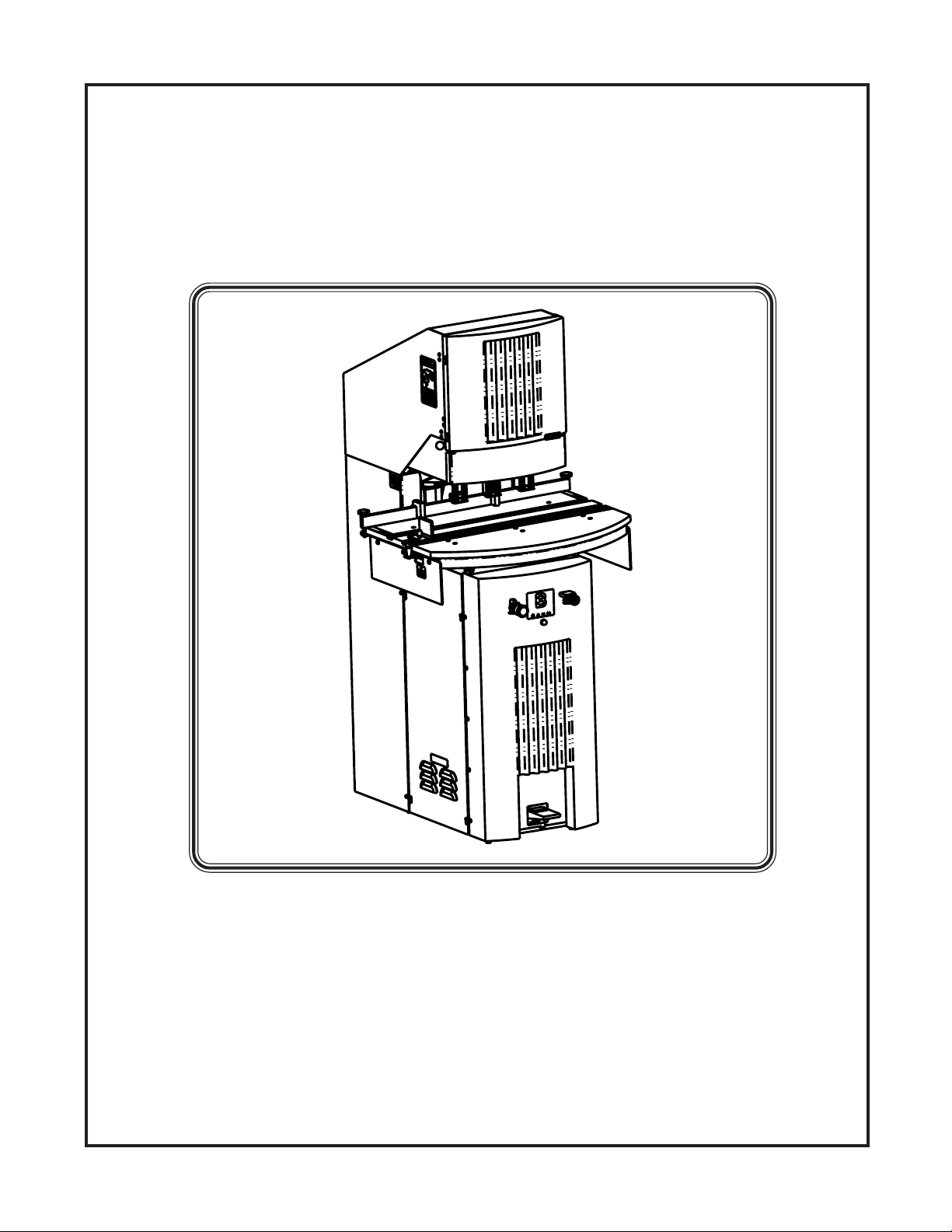
D3 P APER DRILL
Your new D3 Paper Drill has been designed to provide you
with years of useful service, provided it is installed, maintained and operated according to the instructions contained
in this manual.
The D3 Paper Drill has the capability for three drill heads,
and is available with a moveable table. Drill bits are
available in sizes ranging from 1/8” to 1/2” in diameter.
SAFETY INSTRUCTIONS
All guards, warning labels, lubrication and caution tags were
placed on this machine for your safety . Take time to become
familiar with all of them. These items must not be removed
from this machine.
The operation and maintenance of this machine should be
clearly understood. Besides exercising standard safety practices, operators, maintenance personnel and any other personnel involved with this drill, should be specifically instructed
on proper maintenance and safe operation of this machine.
All safety mechanisms are provided for your protection and
must not be altered.
Carefully remove the wood frame and look in waste can covers
to find these items. Back gage is located inside of door on left
side of Drill. Be sure to check off the parts received against the
packing list. Examine the machine carefully for any physical
signs of shipping damage.
The machine is fastened to the skid with two bands. carefully
remove the two bands. Remove the drill from the skid by lifting
between the 2 x 4’s that the drill is sitting on. On the bottom of
the drill are four leveling screws, use these screws to level the
machine.
BACK GAGE INSTALLATION
Place the back gage bar at the rear of the table top. Insert the
two clamp knobs through the clearance holes provided in the
bar. Screw the clamps onto the bottom of the threaded rod that
extends from the clamp knobs. Place the two back gage blocks
on the bar so that the thumbscrews are pointing toward the rear
of the machine. Set the bar using the scales on the right and left
sides of the table.
SIDE GAGE INSTALLATION
Slide the side gage assembly into the T -slot provided in the table
top. Slide the side gage to a location desired on the table scale
and tighten the knob by hand.
WARNING
Do not operate this machine without all
guards in place.
Do not make any adjustments or perform any
maintenance on this machine with power on.
Keep the machine and the work area clean and free
of spills, to prevent accidents.
Be certain to replace any safety decals that may
have been detached for any reason.
INSTALLATION INSTRUCTIONS
This machine is shipped inside a protective wood frame. The
following parts are packaged inside the machine at the factory:
Waste Can Wood Blocks
Back gage Bar Drill Sharpener
Back gage Blocks Side Gage
T ools Instruction Manual
WASTE CAN INSTALLATION
Slide the waste can into the opening in the side of the drill.
T00LS
A convenient accessories drawer has been provided under the
top guard.
HYDRAULIC SYSTEM
Checking the hydraulic oil level in the reservoir is done by removing the Fill Cap. The return line hose may remain connected.
The oil level must be just below the fitting that the Fill Cap fits
into. Do not overfill.
The hydraulic system has a flow control valve, which regulates
the speed that the drill bits decend through the paper. Turning
the flow control knob clockwise increases the speed of the descent. Turning the knob counter -clockwise will slow down the
descent of the drill bits.
TP10429-1 4
When using drill bits with a diameter under 1/4”, it is recomended
to slow down the descent of the bits, decreasing the probablility
of bits breaking and clogging.
Page 5

ELECTRICAL SYSTEM
Check the serial number tag on the top of the head casting (next
to tensioner) for voltage/phase/hertz and amperage required.
This tag also lists the time delay fuse amperage and the wire
size for the supply conductor.
STARTING
T wo electric motors provide the power for this machine; one is
for the hydraulic power system and the other is for the spindle.
The electric motor for the hydraulic system drives a hydraulic
pump that creates the force to push the drill heads down. The
spindle motor drives the drill head spindles through a set of
belts and pulleys.
The two motors are started by pushing the start button.
Both motors are turned off by a red mushroom stop pushbutton
located on the left side of the panel. This is a safety feature that
stops the entire machine.
WARNING
This machine is equipped with a safety interlock system which
prevents the spindle motor from being started when the hinged
top cover is opened, and automatically turns the spindle motor
off if the cover is opened after the spindle motor is turned on.
This safety feature is provided to prevent accidental contact
with moving parts. This feature must not be altered or tampered with.
F) If bits seem to stall when drilling, the belt may need to be
tighter.
G) For adjusting the depth of the drill bits, rotate the brass knurled
knob on the drill head. The proper drill bit depth is a slight
indentation into the wood block.
H) For drilling one or two holes you must remove the bits
from the other heads.
You cannot remove drill heads.
I) If the table on the D3 drill is moveable. The template
supplied with the drill has three locking positions; center, max.
left, and max. right.
J) To move the table, push down the handle on the left side of
the table, once you start moving the table, release the handle
and it will fall into the next position in the template.
OPERATION
A) Open the hinged top cover.
B) Insert the drill bits into the drill head spindles.
C) Make sure that the retainer on the spindle is down over the
horseshoe lock washer.
D) The left edge of the drill head needs to be lined up with the
scale behind the drill heads.
E) To move the drill heads, first loosen the belt tensioner by
loosening the handle on top. Second, loosen the handle on the
drill head to be moved, then slide the drill head to the desired
location and tighten the handle. Then, using the racket on the
belt tensioner, rotate the belt tensioner counter clockwise until
the belt is tight. Then tighten the handle on top.
Caution: Make sure the belt is seated on each
pulley while tightening
5 TP10429-1
Page 6

DRILL HEAD AND BIT TIPS
7. USE DRILL EXTENSIONS
1. KEEP DRILLS SHARPENED
A dull drill bit can be a major cause of drill bit breakage. Sharpening and cleanliness help prolong bit life. Imperfections in
drilling indicate dull drills. A dirty drill bit will clog and will
cause pressure build up that can split or break the drill bit.
Clean the drill bits of all chips after each use and apply a light
film of oil to the inside and outside. When drilling coated stock,
the chips frequently are compacted into slugs inside the drill
bit, it is important that the drills be cleaned out immediately
before the drill cools or the slugs will become a solid mass that
will cause the drills to break the next time they are used.
2. LUBRICA TE DRILLS
Use the drill lubricant sticks that are provided with your drill
to assure better chip passage and to avoid overheating of the
drills. T ouch the side of the drill bit near the cutting edge with
the end of the lubricant stick. Try to coat the inside of the bit as
well. Squeaking, slight burning or smoking is a common sign
that lubrication is needed.
3. SET THE DRILLS CORRECTLY
Drill extensions help chips flow up into the spindle and out of
the ejection slot. There are two sizes of extensions: one extension fits 1/8" through 5/32" drills; one extension fits
3/16”, 7/32”, and 1/4" drills. The larger diameter drills do not
need extensions. Extensions help prevent drill breakage, especially when drilling coated stock.
8. REMOVE DRILLS FROM HEADS WHEN FINISHED
Depending upon atmospheric conditions, if the drills are left in
the spindles overnight or for the weekend, they may rust. If this
occurs, they will be extremely difficult to remove.
Do not cut too deeply into the wood blocks. The drills should
just touch the block enough to make an impression and cleanly
drill through the bottom sheet. Do not set the drills deeper into
the blocks after drilling, move the blocks or flip them over or
turn them end for end to get a new cutting surface. The use of
chipboard (cardboard) below the lift when drilling can sometimes improve the hole quality .
4. CHECK BELTS
Loose belts can slip and cause overheating of drills. Tighten if
necessary , but be careful not to over tighten.
5. CHECK FOR RUNOUT OR WOBBLE
Drill head spindles that are worn or bent as a result of misadjustment can cause drill breakage. Have the spindles
replaced immediately.
6. INSPECT DRILL SHARPENER
Check the cutting edges of the carbide cutting tool for nicks
and sharpness. Don’t let the drill drop on the cutting tool or the
cutting edge will be damaged on the tool. Use gentle pressure
when sharpening. T oo much pressure will spread the mouth of
the drill, causing breakage. only a few turns will sharpen the
drill.
TP10429-1 6
Page 7

SPECIFICATIONS
DRILLING:
ELECTRICAL:
Motors: 1 hp pump
1 hp spindle
Available in:208-22OV/1 phase/60 hz at 25 amps
208-22OV/1 phase/50 hz at 25 amps
Electrical safety interlock that prevents spindles from
rotating when hinged cover is raised.
One stop button turns off the entire machine.
Indicator light is provided that tells the operator when a.
motor is overloaded.
Motor contactors have automatic reset feature.
HYRAULIC:
1.10 gpm pump at 1640 rpm @ 60hz
1 gallon reservoir
Maximum number of drilling heads: 3
Drill bit sizes available: 1/8" to 1/2"
Max drilling capacity: 3 heads with 3/8” drill bits - 2” max.
The number of 1/2” bits that can be used will vary due to
many variables including: paper types, lift size, drill descent,
speed, etc.
Vertical drill bit adjustment in drill heads: 5/16"
Maximum center to center distance of heads: 11"
Minimum center to center distance of heads: 2.0"
Maximum distance from center of drill to back gage: 5.83"
Maximum distance between holes: 25.25" (MT)
Maximum distance between holes: 10.00” (ST)
Min. distance between holes (MT): Adjustable stops: .50"
Min. distance between holes (ST): 2.00”
Preset relief valve protects system
0il: Anti-wear hydraulic oil
Mobil DTE 24
Mobil DTE 25
Mobil DTE 26
Energol HLP-32
Energol HLP-46
MAINTENANCE CHECK LIST
Daily: 1. Sharpen drill bits
2. Lubricate drill bits
Monthly: 1. Check hydraulic reservoir oil level
Yearly: 1. Change hydraulic reservoir oil
Floor space required for drill: 43" x 49"
Machine height: 67"
Shipping weight (approximate): 630 lbs.
VALUE ADDED STANDARD FEA TURES:
Hand drill sharpener and sharpening stone
T ool and accessories drawer
No tools needed for removing heads from the drill
“Drill Ease” drill bit lubricant sticks
Enclosed waste chute eliminates excessive chips on the floor
Large capacity, and easily removable waste can
Safety interlock hinged cover stops rotation when cover is
up
4 wood blocks
2 retainer clips
3 drill bit extensions
1 tool kit
7 TP10429-1
Page 8

ACTUAL DRILL SIZES
DIAMETER: INCHES/(METRIC)
1/8" 5/32" 3/32" 7/32" 1/4" 9/32" 5/16" 11/32" 3/8" 13/32" 7/16" 1/2"
3-1mm 4mm 5mm 5-5mm 6mm 7mm 8mm 9mm 9-5mm 10mm 11mm 12-5mm
CAPACITY: INCHES/(METRIC)
1" 1-1/8" 1-1/2" 1-3/4" 2" 2" 2" 2" 2" 2" 2" 2"
25mm 25mm 35mm 40mm 50mm 50mm 50mm 50mm 50mm 50mm 50mm 50mm
TP10429-1 8
Page 9

TROUBLESHOOTING
PROBLEM POSSIBLE SOLUTIONS
1) Drill heads a) Check motor rotation of
won’t come down drive shaft with arrow on
motor. Switch two wires of the
incoming electrical cable to
correct rotation.
b) Relief valve may need adjusting.
Contact the Baum Dealer where
you purchased your D3 drill for
assistance.
2) Spindles stall a) Dull drills, sharpen or replace
b) Check for low voltage
c) Check for belt drive tightness
d) Check for plugged drill bits
3) Drill head won’t a) Check for broken lift springs.
come back up Contact the Baum Dealer where
you purchased your D3 drill for
assistance.
b) Oil guide shafts and pry up head
4) Insufficient a) Check oil level
hydraulic pressure
b) Check voltage
c) Check relief valve. Contact the
Baum Dealer where you purchased
the D3 drill for assistance.
5) Frequent drill a)Dull drills; sharpen. Or
bit breakage replace
b)Use drill extensions
c)Cutting too deep in wood
blocks, reset properly
d) Excessive wobble of bits,
replace spindles
e) Drill less stock height (covered
stock)
f) Clean out drill bits after end of
each use.
9 TP10429-1
 Loading...