

Page 1
BA U
M
BAUM 26/BAUM 30
1ST STATION FOLDER
W/CONTINUOUS FEED
INSTRUCTION MANUAL
©Baumfolder Corp., 2004 Printed in U.S.A. TP10476-1
PAGE 1 TP10476-1
Page 2

© 2004 BAUMFOLDER CORPORATION
All Rights Reserved
WARNING
• Do not operate this machine without all guarding in place.
• Do not make adjustments or perform maintenance on this machine with power on.
• Keep the machine and the work area clean and free of spills to prevent accidents.
• Be sure to replace any safety decals that may have been detached for any reason.
Baumfolder Corporation reserves the right to make changes in design or to make additions or
improvements in its products without imposing any obligation upon itself to install them on its
previously manufactured products. It is recommended that modifications to this equipment not be
made without the advice and express written consent of Baumfolder Corporation.
FOLDER IDENTIFICATION
MODEL NO: _______________________________ SERIAL NO: _____________________________
SALES AGENCY: ____________________________________________________________________
INSTALLED BY: _____________________________________________ DATE: ________________
PHONE NO: _______________________________
TP10476-1 PAGE 2
Page 3

CONTENTS
DESCRIPTION PAGE
I.) Safety .................................................................................................................................................................. 6
II.) Warning Labels ................................................................................................................................................. 9
III.) Introduction Overview ..................................................................................................................................... 10
IV.) Transportation/Installation .............................................................................................................................. 10
V.) Electrical Connections .................................................................................................................................... 11
1.0 .Wiring the Unit ................................................................................................................................... 11
1.1 . Pump & Blower Connections .............................................................................................................. 11
VI.) Feeder Operation .............................................................................................................................................. 12
1.1 . Air and Vacuum Setting....................................................................................................................... 13
1.2 . Sheet Separation and Suction Force .................................................................................................... 14
1.3 . Register Table and Double Sheet Detector ......................................................................................... 15
VII.) Baumset Adjustment ........................................................................................................................................ 16
1.0 .Adjusting Folding Rollers ................................................................................................................... 16
VIII.) Installing Fold Plates ....................................................................................................................................... 17
IX.) Operator Controls ............................................................................................................................................ 17
1.0 . Setting Folding Speed ......................................................................................................................... 17
1.1 .Setting Stacker Belt Speed ................................................................................................................... 17
1.2 .Emergency Stop Button ....................................................................................................................... 17
1.0 Control Panel BAN-5 ................................................................................................................................ 18
1.1 . Displays............................................................................................................................................... 18
1.2 .Machine Status Indicators .................................................................................................................. 18
1.3 .Machine Control Pushbuttons ............................................................................................................ 19
1.4 . Keypad Buttons with Selection Indicators .......................................................................................... 19
1.5 . Keypad Buttons for Selection Adjustments ........................................................................................ 19
2.0 RUN M ODE F UNCTIONS ................................................................................................................................20
2.1 . Machine Setup and Diagnostic Mode ................................................................................................. 20
2.2 . Counter Setup Mode ........................................................................................................................... 26
2.3 .Learn Mode ......................................................................................................................................... 27
2.4 . Make Ready Mode .............................................................................................................................. 28
2.5 .Network Job Mode .............................................................................................................................. 28
2.6 .Production Mode ................................................................................................................................ 29
3.0 CONTROLLER I NPUT D ESCRIPTIONS .............................................................................................................. 30
4.0 Process Variables ..................................................................................................................................... 32
4.1 . Total Input Count ................................................................................................................................ 32
4.2 . Total Output Count ............................................................................................................................. 32
4.3 .Batch Down Count .............................................................................................................................. 32
4.4 .Number of Batches .............................................................................................................................. 32
4.5 . Current Rate ......................................................................................................................................... 32
4.6 . Main Drive Run Time .......................................................................................................................... 32
4.7 . Main Drive Velocity ............................................................................................................................. 32
4.8 .Waste Count ....................................................................................................................................... 33
5.0 COUNTER SETUP VARIABLES ....................................................................................................................... 33
5.1 . Batch Preset......................................................................................................................................... 33
5.2 . Batch Output Type .............................................................................................................................. 33
5.3 .Batch Output Time .............................................................................................................................. 33
5.4 . Sheet Length ....................................................................................................................................... 33
5.5 . Gap Length .......................................................................................................................................... 33
5.6 . Suction Length .................................................................................................................................... 33
6.0 SYSTEM M ESSAGES AND R UN M ESSAGES ....................................................................................................... 34
6.1 . Power-Up Fault Messages .................................................................................................................. 34
6.2 . Run Time Fault Messages ................................................................................................................... 35
6.3 . Machine Run Error Messages ............................................................................................................. 36
PAGE 3 TP10476-1
Page 4

CONTENTS
DESCRIPTION PAGE
X.) Setting Fold Plates ........................................................................................................................................... 38
XI.) Scoring/Slitting/Perforating ........................................................................................................................... 39
1.0 . Slitter Shaft Removal ........................................................................................................................... 39
1.1 . Scoring ................................................................................................................................................ 39
1.2 . Perforating ........................................................................................................................................... 39
1.3 . Slitting ................................................................................................................................................. 39
1.4 . Trimming Edges of Booklets ................................................................................................................ 40
1.5 . Trimming a Strip from Center of Sheet ................................................................................................. 40
1.6 . Blade Installation ................................................................................................................................. 40
XII.) Lubrication/Maintenance ................................................................................................................................. 42
XIII.) Technical Specifications & Accessories ......................................................................................................... 43
XIV.) Troubleshooting ............................................................................................................................................... 44
XV.) Service ............................................................................................................................................................ 46
TP10476-1 PAGE 4
Page 5

List of Tables
DESCRIPTION PAGE
Table 1. Machine Setup Parameter List ................................................................................................................................ 20
Table 2. Statistics ................................................................................................................................................................. 21
Table 3. Machine Settings .................................................................................................................................................... 22
Table 4. Machine Diagnostic Parameter List ......................................................................................................................... 23
Table 5. Safety Settings ........................................................................................................................................................ 24
Table 6. Machine Statistics .................................................................................................................................................. 24
Table 7. Machine Operating Statistics ................................................................................................................................. 25
Table 8. Output Type Animations ....................................................................................................................................... 26
Table 9. Count Source Selection ........................................................................................................................................... 26
Table 10. Learn Mode Status ................................................................................................................................................ 27
Table 11.Suction Mode Symbols .......................................................................................................................................... 27
Table 12. Suction Length Function ....................................................................................................................................... 28
Table 13. Determining the Large Display Contents ............................................................................................................... 29
Table 14. Reset Mode Selection ............................................................................................................................................ 29
Table 15. Inputs .................................................................................................................................................................... 30
Table 16. LED Status Indicators ............................................................................................................................................ 32
Table 17. Output Delay and Duration ................................................................................................................................... 33
Table 18. Power Up Fault Messages ..................................................................................................................................... 34
Table 19. Run Time Fault Messages ..................................................................................................................................... 35
Table 20. Machine Run Error Messages ............................................................................................................................... 36
PAGE 5 TP10476-1
Page 6

FUNDAMENTAL SAFETY
INSTRUCTIONS!
The diagrams and descriptions used in these instructions are not necessarily
applicable to the specification of the machine supplied. Modifications, made
for reasons of technical or operational improvement, are embodied without
notice.
TP10476-1 PAGE 6
Page 7

FUNDAMENTAL SAFETY
INSTRUCTIONS!
These operating instructions are designed to familiarize
the user with the machine and its designated use.
The instruction manual contains important information on
how to operate the machine safely, properly and
most efficiently. Observing these instructions helps to
avoid danger, to reduce repair costs and downtimes and
to increase the reliability and life of the machine.
In addition to the operating instructions and to the mandatory rules
and regulations for accident prevention and environmental protection
in the country and place of use of the machine, the generally
recognized technical rules for safe and proper working must also be
observed.
The following signs and designations are used in the
manual to designate instructions of particular importance.
1.0.3
The machine/installation is designed exclusively for paper finishing
of minimum and maximum sheet sizes (see corresponding operating
instructions). Using the machine/ installation for purposes other than
those mentioned above is considered contrary to its designated use.
The manufacturer/supplier cannot be held liable for any damage or
injury arising from such misuse. The risk of such misuse lies entirely
with the user.
Operating the machine within the limits of its designated
use also involves observing the instructions set out in the
operating manual and complying with the inspection and
maintenance directives. The working temperature of the
machine should range between 0° and 55° C.
1.1 Organizational measures
1.1.1
The operating instructions must always be at hand at the
place of use of the machine/plant, e.g. by stowing them in the tool
compartment or tool box provided for such purpose.
Important
(refers to special information on how to use the
machine/plant most efficiently)
Attention
(refers to special information and/or orders and
prohibitions directed towards preventing
damage)
Danger
(refers to orders and prohibitions designed prevent injury or extensive damage)
1.0 Basic operation and designated use
of the machine/plant
1.0.1
The machine /plant has been built in accordance with
state-of-the art standards and the recognized safety rules.
Nevertheless, its use may constitute a risk to life and limb
of the user or of third parties, or cause damage to the
machine and to other material property.
1.1.2
Personnel entrusted with work on the machine must have
read the operating instructions and in particular the chapter on
safety before beginning work. Reading the instructions after work
has begun is too late. This applies especially to persons working
only occasionally on the machine, e.g. during setting up or
maintenance.
1.1.3
For reasons of security, long hair must be tied back or
otherwise secured, garments must be close fitting and no
jewelry, such as rings, may be worn. Injury may result
from being caught up in the machinery or from rings
catching on moving parts.
1.1.4
Observe all safety instructions and warnings attached to
the machine/plant.
1.1.5
See to it that safety instructions and warnings attached to
the machine are always complete and perfectly legible.
1.1.6
In the event of safety relevant modifications or changes in
the behavior of the machine/plant during operation, stop
the machine/plant immediately and report the malfunction
to the competent authority/person.
1.0.2
The machine/plant must only be used in technically perfect
condition in accordance with its designated use and the
instructions set out in the operating manual, and only by
safety-conscious persons who are fully aware of the risks
involved in operating the machine/plant. Any functional
disorders, especially those affecting the safety of the
machine/plant, should therefore be rectified immediately.
1.1.7
Never make any modifications, additions or conversions
which might affect safety without the supplier’s approval.
This also applies to the installation and adjustment of
safety devices and valves as well as to welding work on
load-bearing elements.
PAGE 7 TP10476-1
Page 8

1.1.8
Spare parts must comply with the technical requirements specified by
the manufacturer. Spare parts from original equipment manufacturers
can be relied to do so.
1.1.9
Report any accident that occurs due to a malfunction of the machine
though all prescribed safety precautions were observed directly to
our agency or to the Heidelberg service department (VFKD).
1.2 Selection and qualification of personnel
- Basic responsibilities
1.3.1.4
Before starting up or setting the machine/plant in motion, make sure
that nobody is at risk.
1.3.2
Special work in conjunction with utilization of the machine/plant and
maintenance and repairs during operation; disposal of parts and
consumables.
1.3.2.1
Always press the emergency (Not-Stop) button first, if you stop the
machine for adjustments or maintenance work which must not be
done while the machine is in operation.
1.2.1
Employ only trained or instructed staff and set out clearly the
individual responsibilities of the personnel for operation, set-up,
maintenance and repair.
1.2.2
Make sure that only authorized personnel work on or with the
machine.
1.2.3
Work on the electrical system and equipment of the machine/plant
must be carried out only by a skilled electrician or by instructed
persons under the supervision and guidance of a skilled electrician and
in accordance with electrical engineering rules and regulations.
1.2.4
Work on gas fueled equipment (gas consumers) may be carried out by
specially trained personnel only.
1.3 Safety instructions governing specific
operational phases
1.3.1 Standard operation
1.3.1.1
Avoid any operational mode that might be prejudicial to safety.
1.3.2.2
For extensive maintenance or repair work, turn off the main power
supply.
1.3.2.3
After making adjustments or after doing maintenance or repair work,
always make sure that all tools or other objects are removed from the
machine. Otherwise they might fall into the machine, causing severe
damage or injuries.
1.3.2.4
Keep the floor around the entire machine clean. Immediately clean
any oil, grease or paint spills up off the floor. Remove tools, cleaning
cloths or paper scraps from all work areas.
1.3.2.5
Never operate a folding machine without buckle plates or deflectors
since these are protective as well.
1.3.2.6
Never clean moving parts of the machine (rollers, shafts) or remove
any test sheets, spoiled sheets or bits of paper in such areas.
1.3.2.7
Observe the adjusting, maintenance and inspection activities and
intervals set out in the operating instructions, including information
on the replacement of parts and equipment. These activities may be
executed by skilled personnel only.
1.3.1.2
Take the necessary precautions to ensure that the machine is used
only when in a safe and reliable state. Operate the machine only if all
protective and safety oriented devices, such as removable safety
devices, emergency shut-off equipment, sound proofing elements
and exhausters, are in place and fully functional.
1.3.1.3
Check the machine/plant at least once per working shift for
obvious damage and defects. Report any changes (incl. changes in the
machine’s working behavior) to the competent organization/person
immediately. If necessary, stop the machine immediately and lock it.
TP10476-1 PAGE 8
1.3.2.8
Brief operating personnel before beginning special operations and
maintenance work, and appoint a person to supervise the
activities
..
.
..
1.3.2.9
If the machine/plant is completely shut down for maintenance and
repair work, it must be secured against inadvertent starting by:
– locking the principal control elements and
removing the ignition key and/or
– attaching a warning sign to the main switch.
Page 9

1.4.1 Electric energy
1.4.1.1
Use only original fuses with the specified current rating. Switch off
the machine/plant immediately if trouble occurs in the electrical
system.
1.5 Description and definition of the safety
labels and pictographs on the machine
Replace damaged pictographs with new ones. The corresponding
reference numbers are indicated.
1.4.1.2
If provided for in the regulations, the power supply to parts of
machines and plants, on which inspection, maintenance and repair
work is to be carried out, must be cut off. Before starting any
work, check the de-energized parts for the presence of power
and ground or short-circuit them in addition to insulating adjacent
live parts and elements.
1.4.1.3
The electrical equipment of machines/plants is to be inspected and
checked at regular intervals. Defects such as loose connections or
scorched cables must be rectified immediately.
1.4.1.4
Necessary work on live parts and elements must be carried out only
in the presence of a second person who can cut off the power
supply in case of danger by actuating the emergency shut-off or
main power switch. Secure the working area with a red and white
safety chain and a warning sign. Use insulated tools only.
1.4.1.5
Only unplug or plug in electrical connectors if the main switch
has been disconnected.
Warning!
Folding rollers rotate in opposite directions.
Keep hands away from rollers while the machine
is running!
Warning!
To avoid bruising, keep hands away when
operating moving machine parts!
Warning!
Do not reach into moving belts!
Warning!
Be careful! Height adjustment devices
might cause bruising!
Warning!
Only operate machine when covers are
closed.
1.4.1.6
Only connect the folding units and no machines of other brands to
the existing connectors. Any electrical connection of STAHL
folding machines with other brands needs our express consent.
1.4.1.7
For electrical connection, observe the prescribed admissible voltage
and frequency.
1.4.1.8
Keep switch cabinets closed.
1.4.2
Oil, grease and other chemical substances
1.4.2.1
When handling oil, grease and other chemical substances,
observe the product related safety regulations.
1.6 Explanation of the pictographs used
in the operating instructions
Warning!
You might risk bruising when
moving the machine.
PAGE 9 TP10476-1
Page 10
INTRODUCTION OVERVIEW
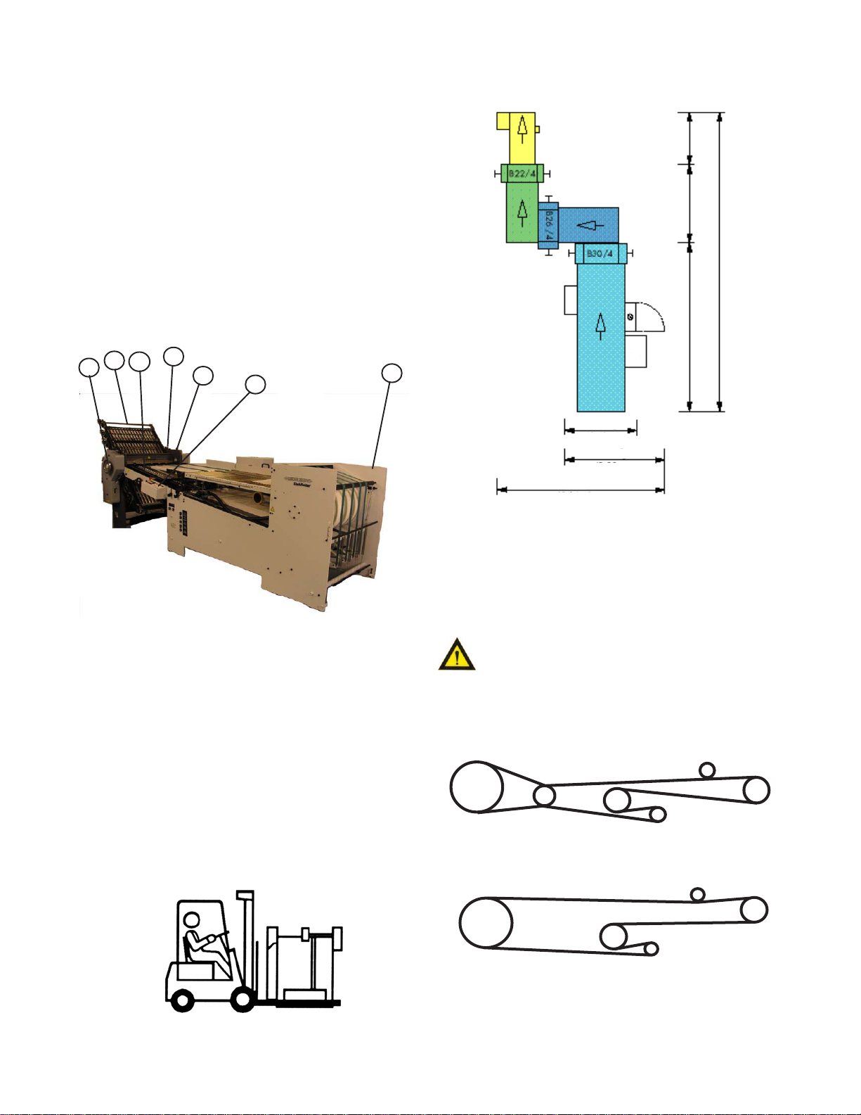
The 1st station (parallel) folder with continuous
feeder contains the following main components (Figure 1):
1. Continuous Feeder
2. Register
3. 1st Station Folder (Parallel)
4. Fold Roller Baumset settings
5. Fold Plates
6. Slitter Shafts (not shown)
7. Delivery (Stacker, not shown)
8. Operator Controls
9. Double Sheet Detector (not shown)
10. Vacuum Pump (not shown)
11. Handwheel
11
5
3
2
4
8
1
(3.03m)
119"
54.5"
(1.38m)
(1.97m)
77.5"
(1.17m)
(1.73m)
(3.78m)
46"
68"
149"
(6.73m)
265"
Figure 1
TRANSPORTATION/INSTALLATION
As soon as you receive your new folder, and before
removing the machine from the skid, check carefully for any
damage to the shipments. If any damage is found, promptly
contact your Baumfolder sales representative.
To lift the folder from the skid, place the fork lift rails
under the crossmembers as shown in Figure 2. Note that the
fork lift must have at least a 1500 lb. capacity.
Remove all rust protection coating after unpacking the
folder.
Remove the connecting bolts from the side frame at the
front of the register. Move the feeder next to the properly
aligned fold head and adjust it so that the holes in the
register and in the side of the folder are at the same height.
Remove the transport supports after you
align the feeder.
Install the drive belts on the folding unit and check
their tension.(Figure 3)
BAUM 26
Figure 2
TP10476-1 PAGE 10
BAUM 30
Figure 3
Page 11

ELECTRICAL CONNECTIONS
1.0 Wiring the Unit (3 phase)
All repair or disassembly work must be performed
by qualified personnel. Before inspecting the
electrical system, always turn the main power
switch OFF before opening the door of the circuit
cabinet.
Check that your power supply meets the requirements
given in the machine specifications. Use an allen wrench to
unlock the circuit cabinet door and open it.
Feed the power supply cable from your distribution
panel through the side of the circuit cabinet. Connect the
customer's supply conductors to the main disconnect at L1,
L2 & L3. Connect the earth ground conductor to the adjacent
ground terminal block.
Before operating the folder for the first time, measure
the line to line voltage to determine where to set the transformer tap. Turn off the main disconnect and move the 7L3
tap of the transformer to the appropriate voltage tap of the
transformer.
Turn the main power switch to the "ON" position.
Switch the pumps on momentarily and check for proper
pump rotation as indicated by the rotation arrow on the
respective pumps. Immediately turn off the pumps if the
rotation is wrong. If both motors are turning in the wrong
direction, switch any two wires at the main disconnect
switch. If only one rotation is incorrect, interchange any two
of the three wires #1, #2, or #3 at their appropriate terminal
block connection point.
1.1 Pump & Blower Connections
Once the pump and blower rotational directions have
been checked and verified, connect the vacuum hose and the
blower hose to their appropriate tubes and secure them with
hose clamps.
PAGE 11 TP10476-1
Page 12
CONTINUOUS FEEDER OPERATION
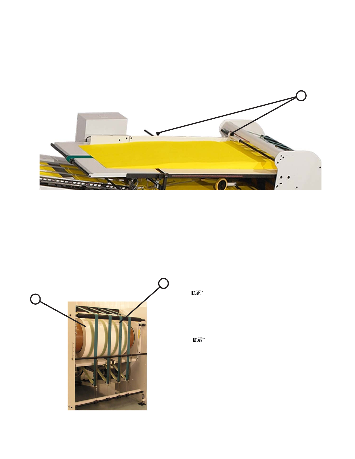
1.0 Loading the Continuous Feeder
Before loading the sheets, use the knobs (Figure 4-1) of
the side guide to set the side for the correct folding format
according to the scale on the feeder. Make certain that you
always maintain the required 8-12 mm gap between the
incoming sheets and the alignment ruler.
The bottom table is equipped with a conveyor belt that is
wide enough to stretch across all usable formats. When you
change sheet formats, you must also adjust the lower side
rails.
1
Figure 4
The deflector belts (5-1) that are wrapped around the
reversing drum operate independently of the loading and
outfeed tables. It will rarely be necessary to change the belt
position. Make certain that the belts are not placed on the
sheet edge (5-2). With the feeder running, use the lever to
move the deflector belts to their proper position.
2
1
Figure 5
When loading the feeder, make certain that the paper
stack does not exceed the maximum height of 3.00" or 8cm.
When feeding a new sheet stack, e.g. when
changing to a new sheet size, help the first
sheet along until it is taken up between the
reversing drum and the deflection belts.
This is done by pressing the stack down on
the middle conveyor belt while pushing the
stack forward at the same time until it is
securely held by the reversing drum and
the deflection belts.
The suction plate blower can be moved or
unscrewed for more convenient sheet
removal.
A movable feeder sensor switch (6-1) is located under the
sucker wheel (6-2). This tab is activated by the leading edge
of the sheet stream, thus providing fully automated control of
the sheet stack feed.
The position of the leading sheet edge at the switch tab
determines the speed at which the stack is advanced; therefore, the stack speed is automatically adjusted to any production speed.
TP10476-1 PAGE 12
Page 13
Stack feeding is stopped automatically if the tab of the
switch is pushed beyond a preset point by the leading sheet
edge (6-3).
Make certain that the switch tab remains
in a verticle position during the sheet
feed operation and that it does not
vibrate (flutter) with each passing sheet.
The position of the switch tab is set at the factory. If
necessary, it can be adjusted both horizontally and vertically
by knobs located on the feeder side frame.
Place the lateral blower (7-1) along the edge of the sheet
stack and the holddown wheels (7-2) on the trailing edge of
the top feeding sheet.
2
Figure 6
1
3
Figure 7
1.1 Air and Vacuum Settings
Use knob (8-1) to adjust the height of the front blowers
and set the angle of the air flow with the lever (8-2) above
the knob. The pointer on the operator side shows airflow
direction.
Use knob (8-3) to adjust the position of the transfer plate.
The distance between the top of the stack and the bottom
of the sucker wheel should be about 1 cm. Lift the
transport plate for large sheets or drooping sheet edges.
Lower the transport plate for small sheets.
1 2
Use knob (8-4) to adjust the air volume that the suction
plate blowers produce.
Use knobs (8-5 thru 8-8) to adjust the air volume produced by the front blowers separately for each section.
Symbols by the knobs indicate the zone which each
knob regulates.
PAGE 13 TP10476-1
Page 14
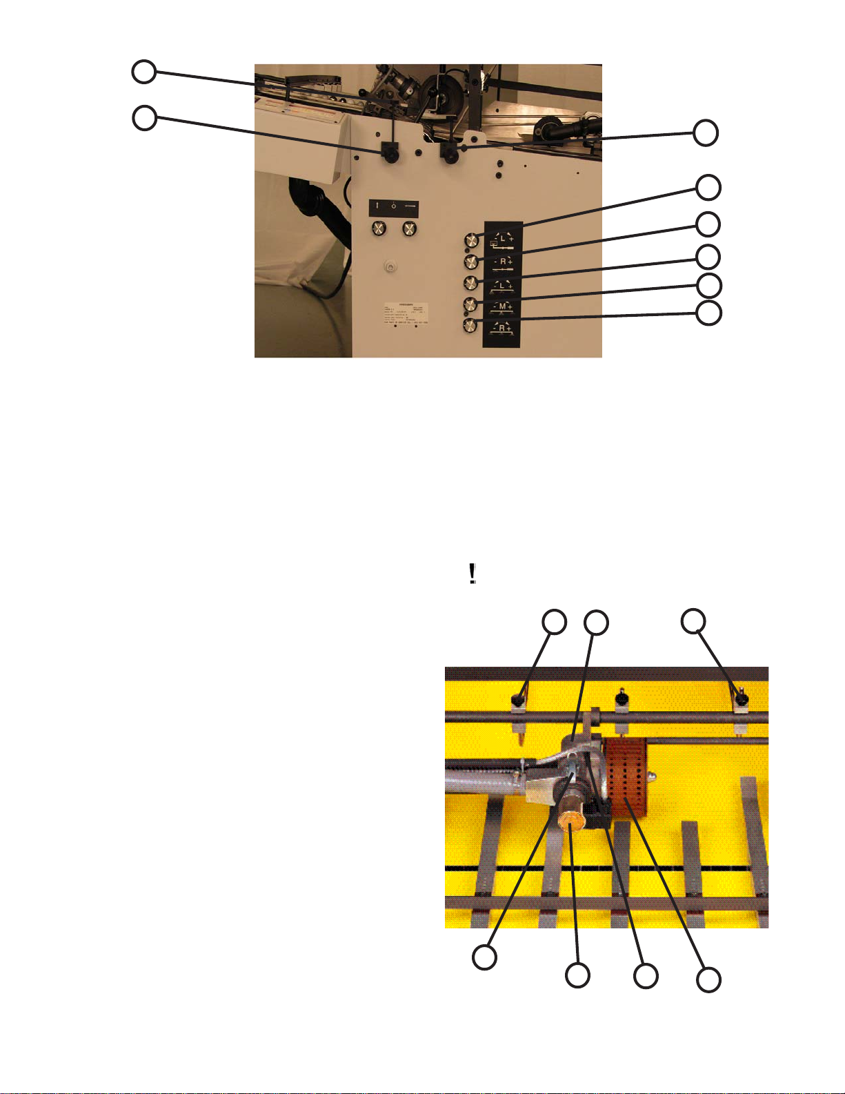
2
1
Figure 8
3
4
5
6
7
8
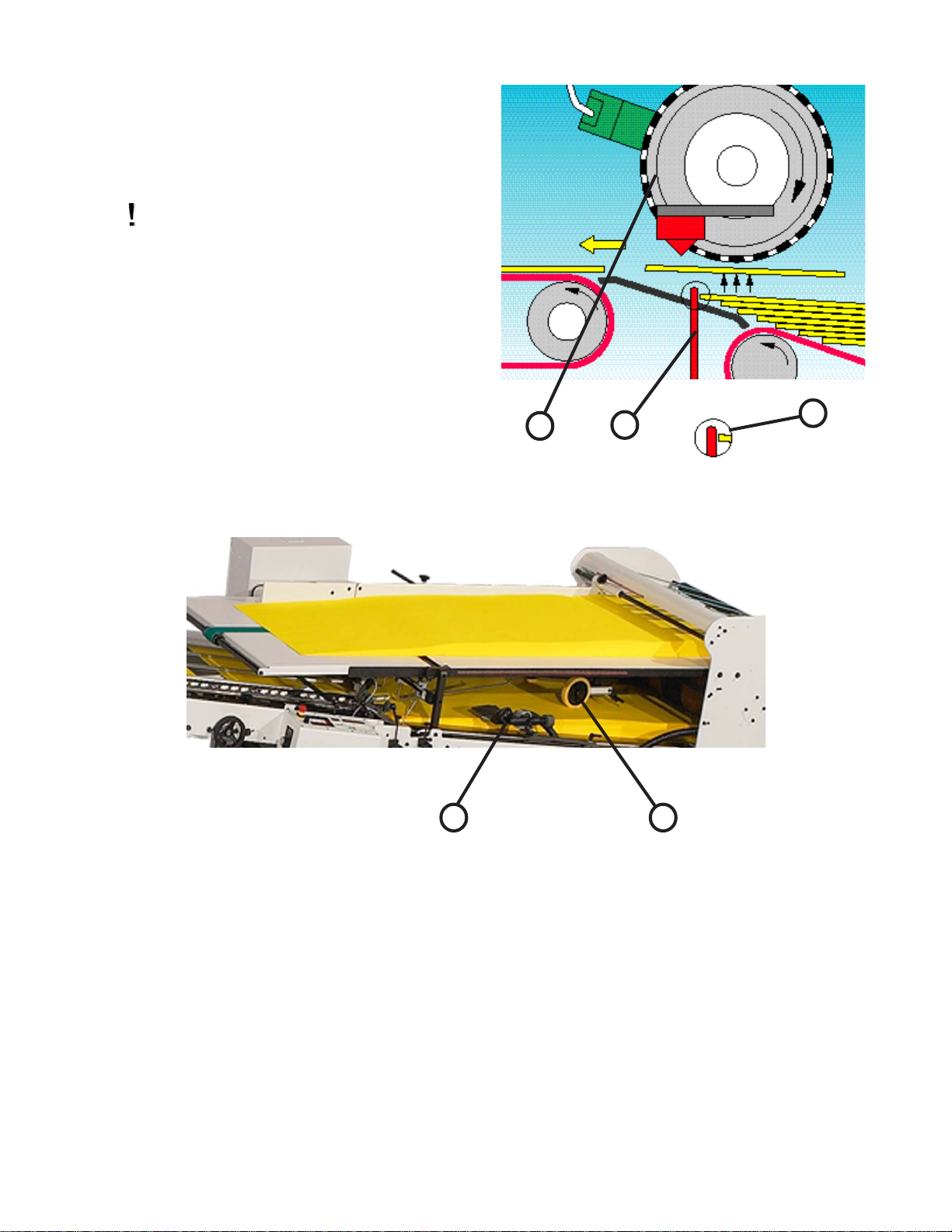
1.2 Sheet Separation and Suction Force
The holddowns (9-1) on the two sides of the sucker wheel
(9-2) should always be positioned slightly lower than the
sucker wheel. This causes the sheet which is sucked against
the wheel to arch up slightly allowing the top sheet to be
peeled away from a second sheet which may be clinging to it.
With stiff and heavy paper, the holddowns must be set so that
the suction wheel can still pick up the sheet.
The suction wheel is controlled by a solenoid valve (9-3).
The normal setting is indicated with a red mark.
The point at which the suction is applied can be adjusted
by swinging the suction point forward or backward with the
knob (9-4).
It may be necessary to move the suction point back if the
leading edge is curled down, or forward if the leading edge is
curled up. This adjustment can be further assisted by raising
or lowering the bridge with the knob.
The solenoid valve can be quickly and easily removed by
releasing the clamps (9-5) to allow dry cleaning of the inner
piston. To clean the piston cavity, unscrew and remove the
back cover (9-6) on the solenoid block and pull a soft cloth
through from the threaded side of the hole. Do not use any
solvent, lubricating agents or air blasts.
Be careful not to damage the piston or it's
bushing.
1
5
Figure 9
6
3
4
1
2
TP10476-1 PAGE 14
Page 15

Adjust the front blowers in such a way that the sheet
stack is fanned across the entire sheet width.
Use less air for thin paper so that the
sheets are not pushed back. The sheets
must not arch because it may cause them
to stick together.
The lateral blowers (suction plate blowers figure 10)
must be positioned so that the blowers rest on the sheet stack
at a slight angle.
The balance is adjusted at the rear counter weight. The
swing span can be adjusted by restricting the lift range. The
suction plate blower is positioned with the front most third of
the blower opposite the guidestop .
1.3 Register Table and Double Sheet Detector
Access to the feed register is provided by the pivoting of
the upper feed table.
1. Turn the lead screw adjustment handle to set the
register drive straight edge to the desired sheet size.
2. The first hole of the marble holder must always have
a plastic ball installed. The other holes can be fitted
with either steel or plastic balls. It is suggested that
one uses as many light weight balls as possible for
optimum sheet alignment. Use at least 1 to 2 steel
balls in the last two holes nearest the fold rolls to
hold the sheet edge in place during folding.
Figure 10
2
1
3. Holddown bars (11-1) are positioned above the
register table to prevent the sheets from rising up as
they are transported along the register. Slide these
bars along the stop rails (11-2) to adjust the
holddowns according to the sheet size.
4. A scale (12-1) indicates when the register straight
edge is positioned at right angles to the fold rolls.
The knurled wheel (12-2) is used to to fine adjust the
guide edge if perforations or folds are skewed. This
fine adjustment can be made while the folder is
running.
5. The double sheet detector (13-1) is set by raising the
arm (13-2) and inserting two strips of the paper (13-
3) being ran between the block (13-4) and the arm.
When doing this, be certain that the paper strips are
slid under the arm of the retainer spring (13-5) so
that they will not fall out when the arm is raised.
Figure 11
1
2
Figure 12
PAGE 15 TP10476-1
Page 16

When a single sheet passes through, the scanner element (13-
6) stays in the off-position. When a double sheet is fed, the
scanner is activated and drawn into the microswitch (13-7) and the
double is stopped. Only the sheet feed is switched off. To remove
the double sheet, raise the arm. After fault removal, reset the
"sheet-feed" start switch.
For thin paper, loosen the knurled screw and reset the lever
spring tension. Afterwards retighten the knurled screw.
7
6
2
3
Figure 13
4
5
BAUMSET ADJUSTMENT
1.0 Adjustment of Folding Rollers
Folding accuracy is determined largely by precise adjustment of the folding rollers.
Using the Baumset precision adjustment device, the correct setting of the rollers can be made simply by inserting the
appropriate paper thickness between the adjustment plates. (See Figure 14)
With multiple thicknesses, insert single strips of the paper being folded equal to the number of sheets passing through
that roller combination..
Since the adjustment spindle acts directly on the folding rollers, clearance settings are exact.
Another method for setting the folding rollers is to insert paper strips between them by touch and adjusting the
pressure by turning the knurled screw.
The numbers on the Baumset adjustment knobs correspond to the buckle-plate numbers into which the sheet is fed. All
upper buckle plates have odd numbers while the plates below are even.
The Baumset adjustment device is correctly zeroed at the factory. If any adjustment is necessary, strips of single paper
thickness should be placed under every adjustment plate. The folding rollers are then reset by drawing strips of uniform
thickness through the appropriate pair of rollers as far as possible to the other side.
At the same time, the knurled screws are adjusted so that the strips can be withdrawn when medium drag is felt. When
this operation is complete, the dial rings are reset to zero.
1
Figure 14
TP10476-1 PAGE 16
Page 17

INSTALLING FOLD PLATES
OPERATOR CONTROLS
Install the fold plates into the folder. Lock the fold
plates in position with the clamping levers (15-1). See "Fold
Pan" section for fold plate setting procedure.
Plug the stacker power cable into the corresponding
outlet on the main control enclosure on the continuous
feeder.
Pull the handwheel (Figure 1-11) to manually turn the
fold rollers to be sure that they are operating smoothly.
Check for any foreign material, and be sure that the deflectors do not touch the fold rollers.
The main operator control panel (Figure 16) is located on
the right side of the register. See the "Control Panel" section
for a detailed description of all the buttons.
1.0 Setting Folding Speed
The speed of the fold rollers may be set while the folder
is running! This is done by adjusting the speed control
potentiometer located on the top left side of the main control
panel. Clockwise rotation speeds the folder up; counterclockwise rotation slows the folder down.
1.1 Setting Stacker Belt Speed
An infinite speed range between high and low is set by
turning the control knob (Figure 17-1).
1.2 Emergency Stop Button
When an emergency stop button (16-1 & 17-2) is
pressed, the result is:
Sheet feed - stop
Folder drive - stop
The pressure/vacuum pump continues to operate. The
emergency stop button must be pulled to release before the
machine can be restarted. An error message "Stop" will
appear on the readout.
The emergency stop buttons are found at the main
operator control panel (16-1) and the delivery control (17-2).
Figure 15
Figure 16
1
1
2
1
Figure 17
PAGE 17 TP10476-1
Page 18
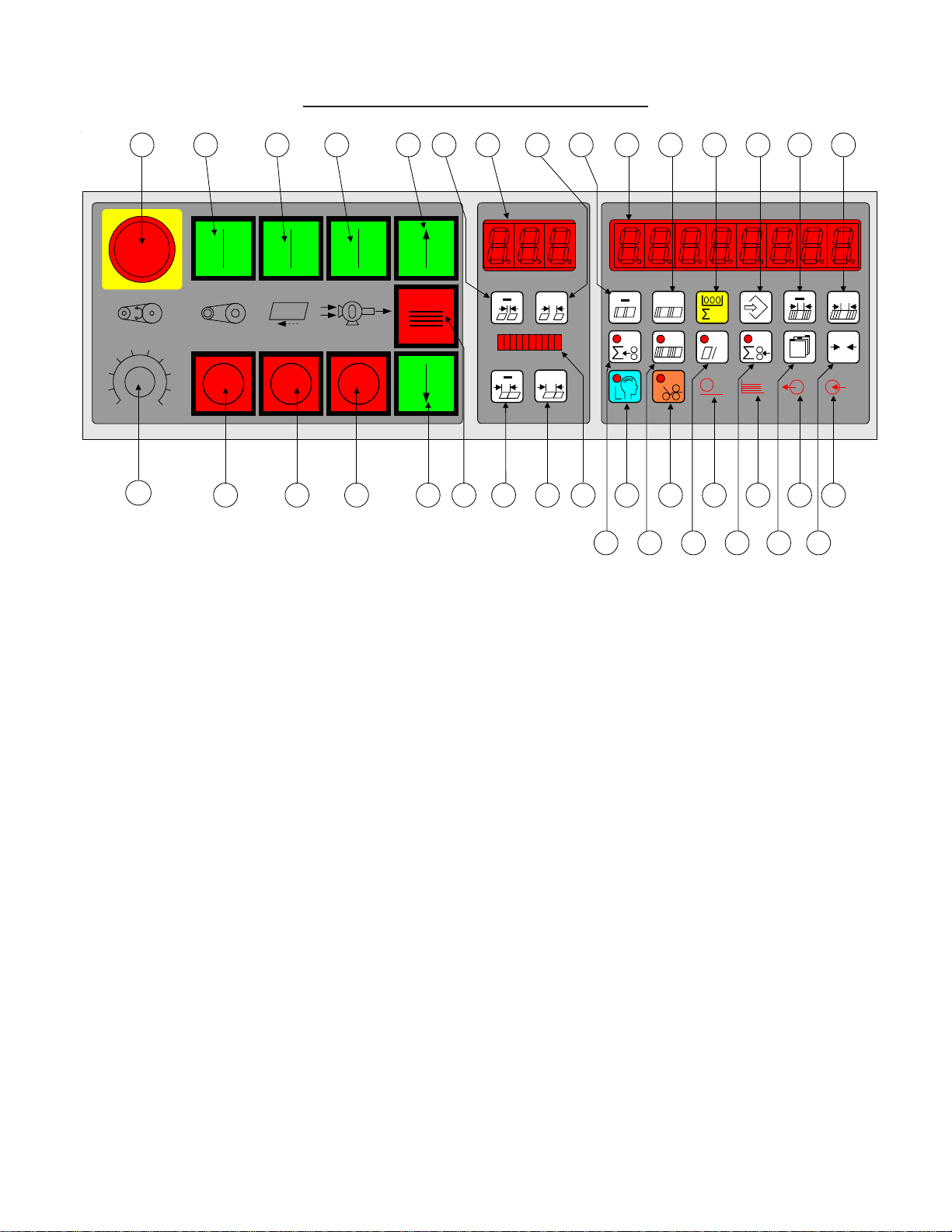
1.DCT500 Control Panel BAN-5
1 29 30 31 32 3325 2824 28 12 10 1417
56
4
3
2
1
DCT 500
7
8
9
10
36
9 13 11 16 26 27 22 23 4 5 7 615 3
Figure 1. DCT500 Control Panel.
01) Large Display
Eight digit multi use display composed of 7-segment LED’s.
02) Small Display
Three digit multi use display composed of 7-segment LED’s.
Displays
+
+
18 19 20 21 34 35
+
h
+
0
03) Ten segment bar graph display
The suction length display is a used to display the Suction Length as a percentage of Sheet
Length. This allows a range from 5% to 50%.
Machine Status Indicators
04) Suction Indicator
The suction indicator will track the suction output. The LED will turn on when the suction
output turns on.
05) Pile indicator
The indicator is lit when the feeder is in automatic feed mode. The indicator will flash if the
feeder is in reverse mode (Continuous Feeder) or moving down (Pile feeder).
06) Input Indicator
The input indicator shows the status of a user selected photo eye.
TP10476-1 PAGE 18
Page 19

07) Output Indicator
The output indicator lights when the Batch Preset PV is reached and the user has selected a
batching option. The output indicator is lit during the time the batching option is active.
Batching options are Feed interruption, Marking table, Speed up table or Kicker.
Machine Control Pushbuttons
08) Main Drive Start
09) Main Drive Stop
10) Pump Start
11) Pump Stop
12) Feeder Start
13) Feeder Stop
14) Pile Feeder Up, Continuous Feeder Start
15) Pile Feeder Stop, Continuous Feeder Stop
16) Pile Feeder Down, Continuous Feeder Reverse
17) Emergency Stop
Keypad Buttons for Selection Adjustments
18) Show Output Count
19) Show Batch Count and Number of Batches
20) Show Current Rate
21) Show Input Count
22) Learn Mode
23) Make Ready Mode
Keypad Buttons with Selection Indicators
24) Gap Minus
25) Gap Plus
26) Suction Length Minus
27) Suction Length Plus
28) Batch Preset Minus
29) Batch Preset Plus
30) Counter Setup Mode
31) Machine Setup Mode
32) Batching Time Minus
33) Batching Time Plus
34) Network Job Mode
35) Reset
36) Potentiometer Speed Adjust
PAGE 19 TP10476-1
Page 20

2. Run Mode Functions
When the folder is started with the RUN/MAINT jumper in the RUN position, the system is enabled for
the user to make machine setups and to fold paper. The counter will start up in production mode, the
normal operating mode of the counter. In this mode, various job parameters can be displayed on the large
display (1), and the small display (2) shows the gap length. The suction length display (3) is active in this mode
and shows the suction length as a percentage of sheet length.
The DCT500 mode select keys perform the same function in all modes, except Counter Setup. This
allows a user to quickly switch between the operating modes on the counter. Select Make Ready is not a
mode unto itself, but rather is a modifier to all modes.
2.1 Machine Setup and Diagnostic Mode
Pushing this key puts the controller in machine setup mode.
Machine setup mode provides a method to view and optionally change operating parameters for the
controller. The decimal points in the large display (1) will move from side to side to indicate that a parameter may be changed. In this mode, the small display gives the selected parameter number, while the
large display (1) shows a parameter value. The suction length display (3) is disabled.
Parameter Selection
+
The plus (25) and minus (24) keys are used to move through the list of available parameters.
Selected Parameter Adjustment
+
+
If the large display (1) decimal points are moving, the set of minus and plus buttons will move through
the set of values for the selected parameter, see table 3 and 4.
2.1.1 Machine Setup Parameters
Table 1. DCT 500 Machine Setup Parameter List
# Function Type Variable Displayed
P00 Input Counter Setup Variables adjustable 1-24 - Std setting 1
P01 Output Counter Setup Variables adjustable 1 to Input Factor SV
Standard setting 1
P02 Tremat Setup Variables adjustable Standard: none 0
Tremat available 1
P03 Knife Setup Variables adjustable Standard : none 0
Knife available 1
P0 4 Ergonomic pile Setup Variables adjustable Standard: none 0
Ergo. available 1
P05 Kicker Setup Variables adjustable Standard : none 0
Kicker available 1
TP10476-1 PAGE 20
Page 21

P00: Input Counter
The number of sheets sensed by the sheet count sensor is multiplied by the factor number displayed, but does not
effect the Batch Down Count, Number of Batches and the Rate.
The Factor can range from 1 to 24. If the Input Factor is changed, it also changes the value of the Output
Counter to the same setting.
P01: Output Counter
This number is added to the Total Output Count but does not effect the Batch Down Count, Number of Batches
and the Rate.
The Factor can range from 1 to Input Counter setting.
P02: Tremat
This selection allows pile feeder machines to switch the tremat function on (1) and off (0)
P03: Knife
The operator must indicate to the machine whether a single cross-fold or several cross-folds are in use in the
machine network. This is done by entering either "1" (Cross fold) or "0" (No cross fold).
Entering "1" (Cross fold) automatically sets the sheet spacing to 10 cm after a single learned sheet. If "0" (No
cross fold) is entered, the sheet spacing is automatically set to 4 cm after a single learned sheet.
P04:Ergonomic stacking
Select "1" to activate the Ergonomic stacking function. "0" indicates that the Ergonomic stacking function is
disabled or not available.
Note: This parameter is only displayed on machines configured with a horizontal pile feeder.
P05: Kicker
Select this parameter to activate/deactivate the kicker function.
0 = Kicker disabled (not available), 1 = Kicker enabled.
2.1.2 DCT 500 Diagnostic Parameters
# Function Type Variable Displayed
P10 Machine Speed Statistics Values Display only Meters per minute
P11 Production time Statistics Values Reset to zero Time in Hours (decimals)
P12 Production stoppage time Statistics Values Reset to zero Time in Hours (decimals)
P13 Setup time Statistics Values Reset to zero Time in Hours (decimals)
P14 Pause Statistics Values Reset to zero Time in Hours (decimals)
P15 Curent Job No. Disabled
P16 Personnel No. Disabled
Table 2 Statistics
P10:Machine Speed
Select this parameter to view the current machine speed expressed in meters per minute (m/min)
P11: Production Time
Select this parameter to view the length of time for which the machine drive is activated - shown in hours (decimals).
PAGE 21 TP10476-1
Page 22

P12: Production stoppage time
Select this parameter to view the time during which the machine is not operating. The Pause function and Sheet
feed are disabled. The time is shown in hours (decimals) and reset to zero for a new job.
P13: Setup Time
Select this parameter to view the Setup time in hours (decimals). The time indicator is reset to zero for a new
job.
P14: Pause Time
Select this parameter to view the time during which the machine is held by the Pause function (P23 enabled).
.
The time is shown in hours (decimals) and reset to zero when new operating data is entered.
P15: Current Job No.
Note: This parameter is only displayed when the network is activated in Service mode. Not available in Software Version 100.300.
P16: Personnel No.
This parameter is only displayed when the network is activated in Service mode. Not available in Software
Version 100.
# Function Operation Key Combin. Variable Displayed
P20 Units Adjustable with Standard Inches
P21 Language Adjustable with Standard English
P22 Network address Function not enabled
P23 Pause Time On/Off Adjustable with Standard - Disabled 0
Adjustable with Activated
Adjustable with Deactivated
P24 Network Function not enabled
P25 Easy Mode Adjustable with Default setting 0
P26 Software Version Automatic from RAM Fixed e.g. dCt 3.0.1
P27 Machine Type In Service mode Fixed e.g. P-36
P28 Serial Port type In Service mode Fixed e.g. off
Table 3Machine settings Network net
+
+
+
Release 1
+
only on C-2020, P-2020
Large contr. display dsP
Meters
German
Codes
P20:Units
Use this parameter to select the unit of measurement (meters or inches) for the values which appear in Displays
01 and 02.
P21: Language
Use this parameter to select the language (English, German or code) for the Display (01) messages.
P22:Network Address
Only indicated when the "Network" option is selected and enabled in the Service menu. Not available in Software Version 100.300.
TP10476-1 PAGE 22
Page 23

P23: Pause
This function is used to activate/deactivate a Pause counter. Select this parameter to display the period of time
for which the pause function was last engaged. It is not possible to feed in sheets when the Pause function is
activated.
P24: Network
Network is only displayed when "Network" is selected and enabled in the Service menu. Not available in
Software Version 100.300.
P25:Easy Mode
This function can only be used on machine types P-b20, C-b20, C-2020 and P-2020.
P26:Hardware and Firmware Version
Select this parameter to display the software installed in Service mode. The logic board type appears in the left
of the display. DCT displays a DCT 500 logic board.
P27:Machine Type
Select this parameter to view the Machine type specified in Service mode.
P28:Serial Port
Parameter setting in Service mode is displayed: dSp, nEt, Off
P30 Status Input Port 1
P30.1 P30.2 P30.3 P30.4 P30.5 P30.6 P30.7 P30.8
Pile Motor Function Pile Down Pile Stop Pile Up Compress. Compress. Drive Start
Energized Control K1 Button Button Button Stop Button Start Button Relay K3
P31 Status Input Port 2
P31.1 P31.2 P31.3 P31.4 P31.5 P31.6 P31.7 P31.8
Pile Sensor Double Pile Down Sheet Start Sheet Stop Thermal Wrong Sheet Emerg.Stop
Sheet Fault Limit Button Button Fault Fault Drive Stop
P32 Status Input Port 3
P32.1 P32.2 P32.3 P32.4 P32.5 P32.6 P32.7 P32.8
Ergonomic Jam on Knife in Jam on Jam on Suction Delivery Count sensor
Pile Load Knife 3 Manual Mode Knife 2 Knife 1 Controller Count Input Suction
Eye fail Wheel
P33 Status Input Port 4
P33.1 N P33.2 P33.3 P33.4 P33.5 P33.6 P33.7 P33.8
Board select Board select Not used Not used Not used Not used Not used Not used
P34 Status Input Port 5
A34.1 A34.2 A34.3 A34.4 A34.5 A34.6 A34.7 A34.8
External Setup LT folding External K2 Checkback Emerg. stop Emerg. stop Machine
Mis-feed sht. Station 2 station device signal station guard open Emerg. stop
P35 Status Output Port 1
P35.1 P35.2 P35.3 P35.4 P35.5 P35.6 P35.7 P35.8
Not used Controller Relief Not used Pile down Pile up Drive Stop Pump
drive valve/Tremat active is active function start (K4)
release ON (K6) Relay (K5)
Button
delivery protection activated
Table 4 Machine diagnostic mode parameters
PAGE 23 TP10476-1
Page 24

P30: Port 1 Inputs
P30 indicates Port 1 input status.
P31: Port 2 Inputs
P31 indicates Port 2 input staus
P32: Port 3 Inputs
P32 indicates Port 3 input status
P33: Port 4 Inputs
P33 indicates Port 4 input status
P34:Port 5 Inputs
P34 indicates Port 5 input status
P35: Port 1 Outputs
P35 indicates Port 1 output status
# Function Operation Key Combin. Variable Displayed
P60 Drive start key delay Adjustable with 0 - 13 secs.
P61 K2 release time Adjustable mit RP2 Adjuster- K2 Delayed release (sec)
(large display)
+
Table 5 Safety settings
P60: Drive Start Delay period (only when A02=0)
Entering the Drive Start Delay period for Station 1 (Settings: 0 to 13.0 sec.) ensures that the paper runs
smoothly after starting if there is any paper still inside the machine. (Station 1: approx. 0.6 sec.)
P61: Display of delayed release for the K2 guard (only when A02=0)
Adjuster for setting the K2 delayed release (Measuring time = 0 to 10 sec.). Adjust with the RP2 poti on the
SGM-3 board. Default setting = approx. 2.5 sec.
# Function Type Variable Displayed
P40 Mon. time for Knife 1 Variable function Input X26/1, P32.5 Time in milliseconds
P41 Mon. time for Knife 2 Variable function Input X26/2, P32.4 Time in milliseconds
P42 Folding station delivery Variable function Input X30/5, P34.3 Time in milliseconds
P43 Counting input Variable function Input X25/5, P32.7 Time in milliseconds
P44 Knife 1 strokes Variable function Input X26/2, P32.4 Time in milliseconds
P45 Knife 2 strokes Variable function Input X26/5, P32.2 Time in milliseconds
Table 6 Machine statistics
P40: Time: Knife 1
Knife 1: Light sensor cover time in milliseconds.
P41: Time: Knife 2
Knife 2: Light sensor cover time in milliseconds.
TP10476-1 PAGE 24
Page 25

P42: Folding station delivery
Display of the time registered by the photoelectric barrier on the folding station delivery.
P43:Counting input
Display of the time registered by the photoelectric barrier on the counting input.
Important:
The counting input is not monitored when Kicker batching is selected.
If the counting input is removed when the machine is activated, error message S-C 5 /B-C 5/STOP 13 is
displayed once and the drive is shut down. The error message is cancelled when the machine and the sheet feed
are restarted. The machine is reactivated by the rear edge at the counting input.
P44: Knife 1 strokes
Select this parameter to view the total number of strokes (in 1000s) for Knife 1.
P45: Knife 2 strokes
Select this parameter to view the total number of strokes (in 1000s) for Knife 2.
# Function Type Variable Displayed
P50 Main time switch ON Machine status Main switch ON Time in hours (decimals)
P51 Machine operating time Machine status Drive Start Time in hours (decimals)
P52 Total sheet feed Machine status Input X14/4, P31.1 Display x 1000 sheets
Table 7 Machine operating statistics
P50: Main time switch ON
Can only be reset in Service mode.
P51:Machine operating time
Can only be reset in Service mode.
P52:Total sheet feed
Select to view the total number of sheets fed in (in 1000s).
The total is reset to zero when new operating data is entered.
Exit Machine Setup Mode
0
Pressing any of these keys will cause the controller to change to a new mode.
h
PAGE 25 TP10476-1
Page 26

2.2 Counter Setup Mode
Batching Time Adjustment
+
Pushing this key puts the counter in counter setup mode.
Counter setup mode is used to prepare the controller to run
a job. The large display (1) shows the batch preset on the
left-hand side and the batching output time on the righthand side. The decimal points in the large display (1) will
move from side to side to indicate that a parameter may be
changed. The small display (2) shows the batching type.
The suction length display (3) is active.
Change Batching Type
+
The minus and plus buttons move through a list of four
output devices. The chosen Type is then activated when the
batch countdown goes to zero. Feed interruption stops the
feeding of sheets for the batching time setting. The speed
up table output activates the marking table output for the
batching time duration. The MKE mode delivers a 100 ms
pulse on the MKE output after awaiting the batching time.
The last, kicker, causes a 20 ms pulse on the kicker output
after the batching time expires. The kicker output may only
be selected if the Count Source is set to delivery. The
output types are represented by animated symbols. The
sequence of frames for the animations is shown in table 5.
Feed Interruption Speed Up Table MKE Table Kicker
Frame
1
Frame
2
Frame
3
Frame
4
Frame
5
Frame
6
Frame
7
Frame
8
The batching time adjustments allow the user to select the
time duration associated with the currently selected output
type. The DCT500 mode supports four output types and
times.
1. Feed interrupt has a range of 0.0 to 9.9
seconds.
2. Speed up Table has a range of 0.00 to 5.00
seconds.
3. MKE Table has a range of 0.000 to 1.000
seconds.
4. Kicker has a range of 0.000 to 1.000 seconds.
Select Count Source
The Input Count and Output Count keys select between
count at the feeder and delivery, respectively. One key
LED will always be lit in Counter Setup to show the
current count source, see table 6. If the output key is
pushed when it’s LED is on, the Batching Type is kicker,
then the DCT500 will activate chasing LEDs in the small
display signifying the start of kicker setup mode. The next
sheet fed through the kicker will be timed from leading
edge to the trailing edge and the kicker delay time will be
set to one half the sheet time. Please note, this must be
redone if the delivery speed is changed.
The batching count source will be the feeder
photoeye.
The batching count source will be whatever is
connected as the delivery photoeye.
Table 9. Count Source Selection
Exit Counter Setup Mode
0
Table 8. Output Type Animations
Suction Length Adjustment
+
This is the same as in run mode.
Batch Preset Adjustment
+
These buttons cause the batch preset to be incremented or
decremented. The preset will be reloaded after the user
leaves the setup mode only if the value has been changed.
TP10476-1 PAGE 26
Pressing any of these keys will cause the counter to
change to a new mode.
Page 27

2.3 Learn Mode
Select Suction Mode
+
This key places the counter in learn mode. Learn mode can
only be activated if the folder is idle.
The learn mode allows the user to setup the suction valve
controller. Both manual and automatic setup is accomplished in this mode. The large display (1) shows two
separate data items. On the left is the suction mode and the
right shows sheet length. The small display (2) shows the
current gap length. The suction length display is active.
During Learn Mode, the Learn Mode key LED indicates
whether a valid sheet has been learned. See table 15.
No valid sheet has been read yet, the system is in
Single Sheet mode.
A valid sheet has been read and the DCT500 has
been setup to run. Single Sheet mode is off.
Table 10. Learn Mode Status
When the LED is on, pushing the sheet start button will
feed a single sheet of paper. If the sheet is fed properly, the
indicator LED will go off. The suction mode will be set to
automatic. The length of the sheet will be set as the current
sheet length. The suction length will be set based on table 9
and the gap length will be set to 1.5 inches/4 cm if P06 is
set to 0 (no knife is active); the gap length will be 4.0
inches/10 cm if P06 is set to 1 (knifes are active).
Gap Length Adjustment
+
These keys toggle between automatic control and cycle
mode. In the cycle mode, the suction valve will be on for
the suction length and off for the remainder of the sheet
length plus the gap length. No adjustments are made for
slipped sheets or process changes. The automatic mode
corrects for process changes and controls the timing of the
suction valve to maintain the user selected gap. If the gap is
less than 2” (50 mm), the right hand decimal point of the
small display (2) will flash and the Leading edge control
will be active. If the gap is greater than or equal to 2.0” (50
mm), full Leading and Trailing edge control is maintained.
Refer to table 8 for suction mode symbol definitions.
TWT-180 Mode
Leading Edge Control
Leading and Trailing Edge Control
Table 11. Suction Mode Symbols
Sheet Length Adjustment
+
The minus and plus keys adjust the gap length. The gap
length range is 0.2” to 98.0” (0.5cm to 250cm).
Suction Length Adjustment
+
The suction length adjustment keys allow the user to
change the amount of suction applied to the current sheet
length. The display shows the percentage in 5% steps. All
of the bars must be totaled to get the value. The range of
adjustment is 5% to 50% of the current sheet length. If the
suction length is manually adjusted while the Learn Mode
LED is on, the suction length will no longer be the Single
Sheet suction length of 6.0 inches. The new suction length
will be based on the current sheet length and suction
setting.
PAGE 27 TP10476-1
The sheet length adjustment keys allow the user to
override the automatic Learn Mode. When the user
changes the sheet length, the suction length will be
adjusted according to table 9. If a different suction length
is desired, the value may be overridden with the suction
length adjustment keys. The sheet length range is 4
inches/10 cm to 98.5 inches/250 cm.
Page 28

Sheet Length Setting Resultant Suction Length Percentage.
Greater than or equal to 30 cm. 30% of Sheet Length
Less than 30 cm., and greater than or equal to 27 cm. 25% of Sheet Length
Less than 27 cm., and greater than or equal to 24 cm. 20% of Sheet Length
Less than 24 cm., and greater than or equal to 21 cm. 15% of Sheet Length
Less than 21 cm. 10% of Sheet Length.
Table 12. Suction Length Function
Exit Learn Mode
0
h
Pressing any of these keys will cause the controller to change
to a new mode.
2.4 Make Ready Mode
When this button is pushed, its LED toggles. When the LED
is on, the folder will only feed single sheets and a batching
output is issued for every two sheets fed. This allows the
operator to easily set up the batching time. Make ready is
deactivated when learn mode is started.
Pressing any of these keys will exit Make Ready Mode.
h
0
Select Job Number
+
+
This set of plus and minus keys step the large display (1)
through pause mode and a list of available job numbers.
While in network job mode, the folder is considered to be
paused.
Load Job and Return to Run Mode
2.5 Network Job Mode
Pushing this key puts the counter in network job mode
This mode is only available if a STA-NET adapter is
installed and activated through maintenance mode. In this
mode the small display (2) always shows the word ‘Job’. The
large display (1) shows either ‘Pause’ or a job number which
can be read from the network. The suction length display is
disabled.
TP10476-1 PAGE 28
When this button is pushed, the selected job will be loaded
into the counter and the counter will return to run mode. If
the large display (1) was showing the message ‘PauSE’, the
network job mode will end, but no job will be loaded.
Exit Network Job Mode
h
0
Pressing any of these keys will cause the counter to change
to a new mode.
Page 29

2.6 Production Mode
Suction Length Adjustment
Enter Run Mode and Select Large Display Content
h
These keys do not operate as mode select keys in counter
setup. In all other modes, the keys both select the large
display (1) contents and place the counter into run mode.
Pushing one of the buttons will light the button’s associated LED and cause the parameter to be displayed. If both
the input and output count keys are pressed simultaneously, then both LEDs go on and the waste count is
displayed.
Large Display Contents
h
h
h
h
Output Count
Batch Count Down
Number of Batches
Current Rate
Input Count
+
The suction length adjustment keys allow the user to change
the amount of suction applied to the current sheet length. The
display shows the percentage in 5% steps. All of the bars must
be totaled to get the value. The range of adjustment is 5% to
50% of the current sheet length.
Reset Function
0
Pressing and holding this key will result in a reset function
being activated after a 5 second countdown. The function is
based on the current large display selection, see table 11. The
large display (1) will show countdown to reset in this manner.
When the button is pressed the message ‘CLr In 5’ will show
on the large display (1). At one second intervals the display
will progress through ‘CLr In 4’, ‘CLr In 3’, ‘CLr In 2’, ‘CLr
In 1’, and finally will show ‘CLEArEd’ when the reset action
is complete.
h
Waste Count
Table 13. Determining the Large Display Contents
h
When the folder is started with the RUN/MAINT jumper
in the RUN position, the system is enabled to fold paper.
The counter will start up in run mode, the normal operating mode of the counter. In this mode, various job parameters can be displayed on the large display (1), and the small
display (2) shows the gap length. The suction length
display (3) is active in this mode and shows the suction
length as a percentage of sheet length.
Gap Length Adjustment
+
The gap length adjustment keys allow the user to change
the current gap length. The range of adjustment is 0.2
inches to 98.0 inches (0.5cm to 250mm).
Reset while showing Output Count will reset all job
variables.
Reset while showing batch data will reset Number
of Batches and reload the Batch Down Count.
Table 14. Reset mode Selection
Exit Run Mode
Pressing any of these keys will cause the counter to change to a
new mode.
PAGE 29 TP10476-1
Page 30

3. Controller Input Description
3.1 Table Inputs
Input Type Connector Point Indicator Name
DCI-1 NPN 24VDC X14/2 P31.1 Pile Sensor
DCI-2 NPN 24VDC X14/5 P14.8 Photoeye Suction Wheel
DCI-3 PNP 24 VDC X25/5 P32.7 Delivery Count Input
DCI-4 NPN 24VDC X15/2 LED 1 Encoder
DCI-5 NPN 24VDC X26/1 P32.5 Sheet Control Knife 1
DCI-6 NPN 24VDC X26/2 P32.4 Sheet Control Knife 2
DCI-7 NPN 24VDC X26/4 P32.3 Knife Manual
DCI-9 PNP 24 VDC X26/8 P32.1 Ergonomic Pile Make Ready
DCI-10 24VDC X30/5 P34.3 Light sensor - Folding station del.
DCI-11 24VDC X30/11 P34.2 Folding station - Make Ready
ACI-1 24VAC X21/1, X21/2, X23/3 P30.8 Drive is on
ACI-2 24VAC X11/3, X22/2, X23/4 P31.8 Emergency Stop/Drive Stop
ACI-3 24VAC X22/3 P31.7 Jammed Sheet
ACI-4 24VAC X22/4 P31.6 Drive Thermal Fault
ACI-5 24VAC X21/5, X23/9 P31.5 Sheet Stop Button
ACI-6 24VAC X21/6, X23/11 P31.4 Sheet Start Button
ACI-7 24VAC X11/2 P31.3 Pile is down
ACI-8 24VAC X11/6 P31.2 Double Sheet Fault
ACI-9 24VAC X23/5 P30.7 Compressor Start Button
ACI-10 24VAC X23/6 P30.6 Compressor Stop Button
ACI-11 24VAC X23/10 P30.4 Pile Stop Button
ACI-12 24VAC X23/12 P30.3 Pile Down (backward) Button
ACI-13 24VAC X23/14 P30.5 Pile Up (forward) Button
ACI-14 220VAC Internal P30.2 Function Control K1
ACI-15 220VAC Internal P30.1 Function Control Pile
ACI-16 24VAC X29/5 P34.5 K2 protective relay monitor
ACI-17 24VAC X29/7 P34.4 External device monitor
ACI-18 24VAC X29/1 P34.8 Emergency stop - control panel
ACI-19 24VAC X29/2 P34.7 Emergency stop - guard
ACI-20 24VAC X29/3 P34.6 Emergency stop - next stations
ACI-24 24VAC X19/2 P34.1 External mis-fed sheet
Table 15. Inputs
3.2 24VAC Inputs
Several mechanical switches are used to indicate machine
faults. These faults are described here. If these faults occur
when the machine is not running, they will display the
associated fault message until the fault is cleared. The only
exception is the Safety fault. The Safety fault always
requires removal of power before the machine can be used
again. If a fault occurs while the machine is running, the
method used to clear the fault varies from fault to fault.
TP10476-1 PAGE 30
Double Sheet
The Double Sheet switch is used to sense multiple sheets
being fed into the machine at the same time. If this fault occurs,
the message “2 Sheet” will be displayed and sheet feeding will
stop. The Drive and Compressor outputs will continue
unaffected. Once the fault has been cleared the machine can
start feeding sheets again by pressing the Sheet Start switch.
Page 31

Thermal
The Thermal input indicates that a motor is overheating. If
this fault occurs, the message “overload” will be displayed,
sheet feeding will stop, the Drive and Pile outputs will be
turned off. Once the fault has been cleared, the machine can
start feeding sheets again by pressing the Drive Start switch
followed by the Sheet Start switch.
Wrong Sheet
The Wrong Sheet switch is used to sense a jam in the
output register. If this fault occurs, the message “Wrng
Sht” will be displayed, sheet feeding will stop, the Drive,
Pile outputs, and RLY1 will be turned off. Once the fault has
been cleared, the machine can start feeding sheets again by
pressing the Drive Start switch followed by the Sheet Start
switch.
3.3 24VDC Inputs
Count
The DCT500 can have two Count inputs. The Count Inputs are
referred to as Feeder (FED) and Delivery (DEL). The Feeder
input is used to increment the Total Input Count. The Delivery
input is used to increment the Total Output Count. Some
machines will only use the Feeder input. Machines that use
both count inputs use a sensor at the input of the machine
(Feeder) to sense sheets feeding into the machine and a sensor
at the output of the machine (Delivery) to sense actual completed sheet output. The difference between the two counts is
called the Waste Count.
Tachometer
The Tachometer input is a high speed input that is used to
sense rotation of the Fold Roll. This input allows the unit to
calculate the speed of the machine, and allow the unit to
determine the length of a sheet being fed through the machine
by counting the number of Tachometer pulses received. Each
tachometer pulse represents a certain distance, see Table 1
Machine Types. The actual distance is dependent on the
machine type selected. The Tachometer Input starts when the
Drive Start switch is pressed. If the tachometer reading is
outside the range of 10 to 230 meters per minute, the unit will
display the message “NO TACH”, and prevent further operation of the machine. To restore operation, the Drive Start switch
must be pressed.
Four additional 24VDC inputs are provided on the DCT500. One
input is for the Tremat unit and two inputs are for the knifefolding unit. The remaining input is for the ergonomic pile load
sensor.
Ergonomic Pile Load Sensor
The Ergonomic Pile Load Sensor is an optional sensor that is
installed for special paper loading applications. If the input is
active and the Down Pile switch is pressed, the Pile Down
output will turn on. Once the Ergonomic Pile Load input
changes to the inactive state, the Down output will turn off. At
this time the operator will load paper onto the pile. Five seconds
after the Ergonomic Pile Load input senses the Pile, the Pile
Down output will turn on. This process will continue until the
operator presses the Pile Stop switch.
Knife unit in manual mode
If this input is active, the unit will operate in manual mode,
where only a single sheet will be fed into the machine each time
the Sheet Start switch is pressed. If this input is active, the LED
in the make ready key is blinking.
Paper under knife eye (1 to 3)
This input is the photo-eye for the knife unit. If the photo-eye is
covered for more than 1.5 times the last saved knife photo-eye
time, the message ‘KnIFE #’ appears on the large display (1)
and the machine stops.
PAGE 31 TP10476-1
Page 32

Reference Name Description
Designator
LED1 Encoder Indicator Encoder input
LED2 Batching Output Batching device pulse output activated. LED illuminated
LED3 Suction cycle valve Suction cycle valve activated, LED illuminated
LED4 K1 Illuminated when K1 relay is activated
LED5 Pile Down Output Down activated. LED illuminated
LED6 Pile Up Output Up activated. LED illuminated
LED7 Pile Controller Pile outputs Up/Down or Forward/Reverse activated, LED illuminated.
LED8 +5VDC Power Supply Power ON, LED illuminated
LED9 +5VDC Supply, grounded Power ON, LED illuminated
LED10 +24VDC Supply, groundedPower ON, LED illuminated
LED11 Kicker Kicker output activated, LED illuminated.
LED12 Regulator release Activated when regulator release is active.
Table 16. LED Status Indicators
4. Process Variables
4.4 Number of Batches
4.1 Total Input Count
Total Input Count PV increments by the factor setting each
time an input is received at the Input Count input. Total
Input Count can range from 0 to 99,999,999.
This process variable is stored in memory in case of a
power outage.
Reset job will clear this process variable to zero.
The Number of Batches is the number of times the Batch
Down Count has reached zero.
Number of Batches can range from 0 to 9999.
This process variable is stored in memory in case of a
power outage.
Reset job will clear this process variable to zero.
Reset batch will clear this process variable to zero.
4.2 Total Output Count
Total Output Count increments by the factor setting each
time an input is received at the Output Count input.
Total Output Count can range from 0 to 99,999,999.
This process variable is stored in memory in case of a
power outage.
Reset job will clear this process variable to zero.
4.3 Batch Down Count
The Batch Down Count is the number of remaining inputs
necessary to trigger a batch output. As input counts are
received, this value counts down to zero. Each input
decrements the Batch Count Down by one. The factor is not
used. When zero is reached, the Batch Down Count resets
to the Batch Preset. The Count input that is used by the
Batch Down Count is determined by the Batching Selection
in Machine Setup. If Feeder is the Batching Selection, the
Batch Down Count will be affected by the Input Count
Input. If Delivery is the Batching Selection, the Batch
Down Count will be affected by the Output Count Input.
Batch Down Count can range from 1 to 999.
This process variable is stored in memory in case of a
power outage.
Reset job will clear this process variable to zero.
Reset batch will load this process variable with the batch
preset.
4.5 Current Rate
The Current Rate is based on the number of Input Count
inputs received during the sample period.
The Current Rate is calculated every second.
The Current Rate is shown as rate per hour.
The Current Rate is rounded to the nearest hundreds.
Current Rate can range from 0 to 99,999,900.
This process variable is not stored in memory.
4.6 Main Drive Run Time
The Main Drive Run Time is the amount of time the Drive
output has been on since the last Clear All Memory Reset
in Maintenance Mode.
This value is displayed in the format HHHHHH.HH.
Main Drive Run Time can range from 0.00 to 999,999.99.
This process variable is stored in memory in case of a
power outage.
Reset ALL in maintenance mode will clear this process
variable to zero.
4.7 Main Drive Velocity
The Main Drive Velocity is the speed of the Tachometer
input.
This value is displayed in meters per minute.
This value is calculated every 300 milliseconds.
This process variable is not stored in memory.
TP10476-1 PAGE 32
Page 33

4.8 Waste Count
The Waste Count is the difference between the Total Input
Count and the Total Output Count.
Waste Count is accessible by pressing and holding the Total
Count button followed by pressing the Total Output Count
button.
Waste Count can range from 0 to 99,999,999.
This process variable is not stored in memory.
Reset job will clear this process variable to zero.
5. Counter Setup Variables
5.1 Batch Preset
This parameter is accessible only in Counter Setup mode for
the DCT500.
This parameter specifies the batch count that will be used by
the Batch Count Down. Zero is the default setting.
This value can range from 0 to 999.
5.2 Batch Output Type
This parameter is accessible only in Counter Setup mode for
the DCT500.
This parameter specifies the batch output type that will be
used when the Batch Count Down reaches zero.
Available choices are Feed (FED), Delivery (DEL), Speed
(SPD), and Table (TBL).
5.3 Batch Output Time
This parameter is accessible only in Counter Setup mode for
the DCT500.
This parameter specifies the output duration or delay that will
be used when the Batch Count Down reaches zero.
Available ranges are determined by the Batch Output Type
selected. The Table below shows the ranges for each output
type.
5.4 Sheet Length
This parameter is accessible in the Learn mode for the
DCT500.
This parameter specifies the length of the paper that will be
fed into the machine.
Available range is 6.0 inches to 59.0 inches. 6.0 inches is
the default selection.
5.5 Gap Length
For the DCT500, this parameter is accessible in Run mode and
Learn mode.
This parameter specifies the length of gap to use between
sheets of paper that are fed into the machine.
Available range is 0.2 inches to 98.0 inches. 2.0 inches is
the default selection.
5.6 Suction Length
For the DCT500, this parameter is accessible in Run mode and
Learn mode.
This parameter specifies the suction length used on a sheet
of paper that is fed into the machine.
Available range is 5% to 50% in 5% increments. 30% is the
default.
Output Delay Duration
Type Min. Time Max. Time Min. Time Max. Time
Feed Not applicable 0.0 Sec. 9.9 Sec.
Table 0.000 Sec. 1.000 Sec. 100 ms
Delivery 0.000 Sec. 1.000 Sec. 25 ms
Speed Not applicable 0.00 Sec. 5.55 Sec.
Table 17. Output Delay and Duration
PAGE 33 TP10476-1
Page 34

6. System Messages and Run Messages
6.1 Power-Up Fault Messages
Messages that are displayed during power on self-test.
If PLC System Errors are shown in the display, call service.
English German Codes TYPE DESCRIPTION
88888 88888 88888 Information The controller is performing its lamp test.
MEM MEM MEM Information The controller is performing its RAM test.
TEST TEST TEST
all blank all blank all blank PLC System The display board is not functioning.
Error Action: Cycle power. If error persists, call service.
ID Fail ID Fail ID Fail PLC System System cannot recognize the controller board.
Error Action: Cycle Power, if error persists, call service.
Error 1 Error 1 Error 1 PLC System The RAM test has found a bad memory location.
Error Action: Cycle Power, if error persists, call service.
Error 2 Error 2 Error 2 PLC System The Pile Safety Relay is stuck on or there is no power supply
Error to the pile circuits.
Action: Check the condition of Relay 1 K1, Fuses F1 and F2, and
X18. Cycle Power, if error persists, call service.
Error 3 Error 3 Error 3 PLC System There is power in the Pile Drive when it is off.
Error Action: Check the condition of Relay 1 K1, Fuses F1 and F2, and
X18. Cycle Power, if error persists, call service.
Error 4 Error 4 Error 4 PLC System The 24VAC inputs have current before the Watchdog
Error relay has been activated.
Action: Check for stuck push buttons, faulty sensors, or loose
connectors.Cycle Power, if error persists, call service.
Error 5 Error 5 Error 5 PLC System The membrane switch panel has a key pressed
Error during the power on self-test.
Action: Cycle Power, if error persists, call service.
Error 6 Error 6 Error 6 PLC System The Watchdog sense circuit indicates Watchdog timer operational
Error before it has been started.
Action: Cycle Power, if error persists, call service.
Error 6.1 Error 6.1 Error 6.1 PLC System Incorrect software in Eprom. Check Eprom type and files.
Error
Table 18. Power Up Fault Messages
TP10476-1 PAGE 34
Page 35

6.2 Run Time Fault Messages
Run time fault messages are only displayed when the unit is in Run mode. Fault errors can still occur, but the corresponding
fault message will not be displayed until the unit is switched to Run mode. Run time fault messages are PLC System Errors or
errors in the whole electric system. It is necessary to call an technician or service.
English German Codes TYPE DESCRIPTION
DCT DCT DCT Information This is the Software-Version(X.X.X)
X.X.X X.X.X X.X.X Note:do not push any buttons until this message has been
cleared from the display
K5 Relay K5 Relay Error 7 PLC System The drive stop relay, K5, is not responding to the controller.
Error Action: Call service.
Button Taste Error 8 Electric A push button is in the wrong state during the version
System Error message display.
Action: Check Buttons & Cycle Power. If error persists call
service
Watchdog Watchdog Error 9 PLC System The Watchdog Timer has elapsed without being serviced.
Error Action: Cycle Power. If error persists call service
No Tach Impuls Error10 Electric The Machine Tachometer is reading a velocity outside of the
System Error range 10 – 230 meters per minute, while the main drive
should be running.
Action: Check the electric. If error persists call service.
Overload Uberlast Error11 Electric A Thermal Overload has been tripped.
System Error Action: Check the electric. If error persists call service
Pile Err Spg. Uber Error12 Electric The Pile Safety Relay is stuck on or there is no power supply to
System Error the pile circuits.
Action: Check the condition of Relay 1 K1, Fuses F1 and F2,
and X18, then cycle Power. If error persists call service
Overrun Uberlauf Error13 Electric The Pile Table has moved past its safety stops.
System Error Action: Check the limit switches, pile table, and wiring. If error
persists call service
2nd Stat 2Station Error14 Electric The Emergency Stop, Wrong Sheet, and Thermal Overload
System Error sense circuits are all indicating failure. Likely cause is Second
Station connector problems.
Action: Check the Second Station Connector, connector X22,
and each individual circuit. If error persists call service
Suction Saugtakt Error15 Electric Short circuit on Suction controller.
System Error Action: Check the electric. If error persists call service
CLR Stop CLR Stop Error16 Electric Emergency Stop activated during power-up sequence
System Error
ERROR 17 ERROR 17 Error17 Electric Incorrect check-back signal received from K2 protective relay.
System Error Power-up sequence (Check-back contact)
ERROR 18 ERROR 18 Error18 Electric Incorrect check-back signal received from K2 protective relay.
System Error Shutdown sequence (Check-back contact)
Table 19. Run Time Fault Messages
PAGE 35 TP10476-1
Page 36

6.3 Machine Run Error Messages
Machine Run Error Messages help the operator to indicate a production problem.
English German Codes TYPE DESCRIPTION
Stop Stop1 Stop1 Information One of the stop buttons is depressed.
ACTION: Make sure all stop buttons are cleared and
connectors X21, and X22 are seated.
Jam Fehlerbg Stop2 Operating The Wrong Sheet Detector has been tripped.
Error ACTION: Clear the fault. NOTE: If the
main drive was running the error condition will remain latched
until the Drive START is pressed.
2 Sheet Doppelbg Stop3 Operating The Double Sheet Detector has been tripped.
Error ACTION:Clear the fault and check X22. NOTE:If sheet feed
was active the error condition will remain latched until the
Sheet Start is pressed.
No Feed Bog. Fehl Stop4 Operating No paper detected within 40 cm of suction valve
Error actuation, while running in an automatic feed mode.
ACTION: Check misfeed, connector X14, and the condition of
the count eye.
Feeder Sensor Stop5 Operating Photoeye at suction valve is covered before sheet start is active.
Error
Long Sht Bg. Lang Stop6 Operating The count eye has been covered for more than 150% of the
Error user set sheet length distance.
ACTION: Check misfeed, connector X14, and the condition of
the count eye.
S -C 1 B - C 1 Stop7 Operating Sheet monitor at Knife 1 activated. Folding problem. Re-learn
Error sheet if necessary, or check light sensor.
S -C 2 B - C 2 Stop 8 Operating Sheet monitor at Knife 2 activated. Folding problem. Check
Error 1 x 4 connector and light sensor if necessary.
.
S - C 4 B - C 4 Stop 9 Operating Sheet monitor at Folding station 1 activated
Error
Snsor DN Stpl Ab Stop 10 Operating The Pile has been moving down for more than 2.5 seconds
Error while the unit is feeding paper.
ACTION: Check Pile Sensor.
Snsor Up Stpl Auf Stop 11 Operating The Pile has been moving up for more than 1.5 seconds
Error while the unit is feeding paper.
ACTION: Check Pile Sensor.
TP10476-1 PAGE 36
Page 37

Stop 12 Stop 12 Stop12 Operating External device error, e.g. Blind sheet monitor - Stop sheet
Error
S -C 5 B - C 5 Stop13 Operating Delivery/Kicker sheet monitor activated. Folding problem.
Error Check 1x 12 connector and light sensor.
Stop 1-1 Stop 1-1 Stop 1-1 Machine Run Emergency Stop key on machine control panel activated.
Error
.
Stop 1-2 Stop 1-2 Stop 1-2 Machine Run Guard open.
Error
Stop 1-3 Stop 1-3 Stop 1-3 Machine Run Emergency Stop key at next station activated.
Error
Stop 1-4 Stop 1-4 Stop 1-4 Machine Run External error. Wrinkled sheet switch on next station activated.
Error
Table 20. Machine Run Error Messages
PAGE 37 TP10476-1
Page 38

SETTING OF FOLD PLATES
Be sure that the adjustment screw (18-2) is in contact
with the support rail on both sides.
Clamp the fold plates with the clamping levers (18-3).
The sheet-stop (18-4) should be moved to the desired
fold length according to the scale (18-5) by loosening the
clamping screw (18-6) and then turning the adjustment wheel
(18-7).
The sheet stop can be set at an angle for sheets that are
not cut square by loosening the clamping screw (18-6) and
turning the front adjustment wheel. The clamping levers (18-
3) must be tightened for this adjustment.
For the fitting of a fold plate, both sides of the stop (18-
1) must have the fold plate so that the adjustment screw
contacts the support rail.
Equal adjustments at both ends are needed to prevent
oblique folds or perforations.
CAUTION:
If the buckle space is reduced, be sure that the fold plate
does not rub against the folding rollers. If this occurs, the
rollers will be damaged. Check for rubbing by manually
turning the handwheel on the folder before turning the power
on.
Figure 19
Figure 18
SETTING OF SHEET DEFLECTORS
Fold plates that are not required for folding can be closed
off when their combination deflectors are fully forward
(Figure 19).
TP10476-1 PAGE 38
Page 39

SCORING/SLITTING/PERFORATING
1.1 Scoring
Your new folder is capable of many different applications
that compliment the folding performance and provide for
greater productivity.
The folder is equipped with slitter shafts that are quickly
set up for the required operation. These shafts accommodate
the mounting of the standard and optional accessories
available that perform scoring, slitting and perforating
functions.
1.0 Slitter Shaft Accessories Removal
Removal of the slitter shafts is accomplished via noncorrosive linchpins (20). Add or remove the parts needed for the
current job using the wrench provided with the machine. See
the following pages for more information on perfing, scoring,
and slitting. Reinstall slitter by reversing the above procedure.
The folder can be used to score a sheet and deliver it flat,
or to score a sheet after a fold or folds have been made.
To ensure accuracy in making right angle folds, always
score the sheet where the fold or folds are to be made. This
applies in all instances when a perforator cannot be used.
Various weights of stock with few or numerous folds
require a different type of score. Some jobs require a
narrow, sharp score, usually when the folds are few, and a
fuller, more rounded score when the job becomes bulky.
The scoring blade is normally mounted on the upper
slitter shaft. Scoring is accomplished by running the
score blade in two rounded scoring collars. The sharpness
and depth of score is controlled by the groove between
these collars. The wider groove produces a wider, more
rounded score; while the narrower groove produces a
sharper, tighter score.
The pullout tires are used to control and support the
sheet as it passes through the slitter shafts.
1.2 Perforating
The folder may be used for perforating either the heads
of booklets (to allow the air to escape in making right-angle
folds) or to slot perforated sheets delivered flat, using blades
and strippers best adapted for a particular job.
Perforating blades are normally mounted on the upper
shaft and ran in a grooved steel collar on the lower shaft with
the flat side of the blade just touching a side of the groove.
A stripper must be used with each perforation. The forked
spring steel stripper requires a little more care in mounting
and is most often used when perforating only, as there is less
tendency for the perforated sheet to break apart.
Figure 20
1.3 Slitting (Cutting) Sheets
Folders may be used to cut folded or flat sheets apart.
Two or more cuts may be made if duplicate sets of slitters
are used.
Be careful when mounting slitter blades to collars in
order to avoid ragged edges which can be caused by two
conditions:
1) Nicks or burrs on the collars or blades. Remove
carefully by filing or using a fine piece of emery cloth.
2) Incorrect mounting of blades. Too much gap between
slitting blades will result in a ragged cut
Space the pull out tires evenly to support the sheet.
PAGE 39 TP10476-1
Page 40

1.4 Trimming Edges of Booklets
Cutting blades and strippers for trimming edges of
booklets or outer edges of circulars running two or more up,
are attached to blade holder collars so that the bevel of the
blades on the upper shaft are directed toward the strip being
trimmed and the bevel of the blades on the lower shaft are
directed away from the strip. Blades mounted in this
manner tend to turn trimmed edges down which helps guide
them to the floor. Blade holder collars are turned out to
allow a set of pull-out tires to be placed close to the cutting
blades, preventing the sheet from buckling or twisting at the
point where the cut is being made.
Use as many additional pull-out tires in the center of the
sheet as necessary.
Set the collar, with blade attached, in the proper position
on the upper shaft. Then move the collar/blade on the lower
shaft so that the flat sides of both blades press snugly
together. Too much space between the blades will cause a
ragged edge on the finished booklet.
Do not attempt to trim less than one-eighth of an inch.
On bulky or heavy sheets a wider trim is necessary.
The strippers used for this work are mounted on the
square bar directly above the shafts. Note that one is right,
and the other left. Place them accordingly. It may be
necessary to bend the strippers slightly to avoid rubbing on
the cross carrier or stacker. Strippers are adjustable for up
and down movement.
1.6 Blade Installation
WARNING!!!
EXTREME CARE MUST BE TAKEN IN THE
REMOVAL AND INSTALLATION OF ALL
SLITTING, PERFORATING, AND SCORING
BLADES. EXCESSIVE FORCE AND/OR
MISUSE CAN CAUSE PERSONAL INJURY,
BREAKAGE, EQUIPMENT AND MACHINE
DAMAGE
All blade attachments are performed in the same
manner. The locking collar of the blade holder is
removed using the provided spanner wrench.
The blade to be changed is moved far enough along
the slitter shaft to permit the blade to be twisted open
and slipped from the shaft via the slit in the blade.
Install the new blade in the reverse order. Twist the
blade so that the slit opens. Slip the blade onto the
slitter shaft, and replace and tighten the locking collar
with the furnished spanner wrench.
1.5 Trimming a Strip from Center of Sheet
A quarter inch trim out of the center of a sheet may be
made. Two or more trims may be made as long as duplicate
sets of cutters and strippers are used and this setup adhered
to.
To remove the trim, place the appropriate center
stripper between two of the cutting blades attached to a
collar.
Attaching blades to collars is very important and should
be done with care. The bevel of the cutting blades on the top
shaft should always be directed toward the strip to be
trimmed.
Before the cutting blades are tightened to the blade
holder collars, slide both the collar and attached blade on
the end of the shaft so that they are accurately aligned. Place
cutting blades on the upper shaft to the proper position
where the cut is to be made. Then place collars on the lower
shaft so that the flat sides are pressed snugly together. Too
much space between the blades will give a ragged edge.
Always examine blades for dullness and nicks which will
cause the same condition.
When blades are in the proper position, mount the
stripper. Be sure the stripper does not touch the sides of the
cutting blades.
With this setup, the trimmed out section automatically
goes between the blades on the lower shaft, where it is
carried down and around and guided to the floor by the
stripper wire.
TP10476-1 PAGE 40
Page 41

Common
Perforating,
Scoring
Setup
Common
Slitting (Cutting)
Setup
PAGE 41 TP10476-1
Common
Edge Trimming
Setup
Page 42

LUBRICATION/MAINTENANCE
Feeder
Vacuum Solenoid Valve The vacuum at the suction wheel is controlled by a
solenoid valve. This can be quickly and easily
removed to clean the piston by loosening the clamping
springs. Be careful not to damage the piston and cylinder.
O-Rings (on vacuum wheel)
Vacuum Pump Loss of vacuum and blow can be caused by clogged filters.
Check periodically. Check vanes for wear after 15,000
hours of service. Refer to parts manual for ordering parts.
Register
Flat Belt Drive Shaft (hex shape) Check for wear periodically. Lubricate with Baum
Lubricant "W" lithium based grease, or equivalent,
periodically.
Support Bars Lubricate the three support bars on which the register
guide slides periodically using Lithium based grease.
Folder
Handwheel Lubricate bi-annually with commercial grade
lubricating oil.
Fold Rolls WARNING: Never clean fold rolls while the machine is
running.
With the folder turned off, rub down the fold rolls with a
cloth dampened with "Surewash". Never immerse fold
rolls into the washing solvent. After cleaning, they should
be rubbed down with a clean dry cloth.
Gear Drive The helical gear drive is lubricated by an automatic
grease dispenser located inside the LH guard. Use
the label on the LH guard to record lubrication change
date [It should be changed every 9 months]. To activate
the dispenser, screw the eye bolt (18-1) into the lid
(18-2) of the dispenser until ring (18-3) comes off. Shake
the cannister when installing to insure that it rattles,
signifying that it has been activated. See parts manual for
replacement dispensers.
WARNING: Never open grease dispenser. Even when
empty, container remains under pressure. If damaged,
caustic liquid may leak out. If contact is made with skin,
Figure 18
Pullout Tires Check periodically for wear. Uneven tires can cause the
flush repeatedly with water.
sheet to twist.
TP10476-1 PAGE 42
Page 43

TECHNICAL SPECIFICATIONS
1526
Maximum sheet size 26" x 44" [66 x 111.7cm]
Minimum sheet size 5.5" x 7.25" [13.9 x 18.4cm]
Maximum folder speed 9000 ipm [230m/min]
Maximum stack height 3" [8cm]
Minimum fold length 2.25" [5.7cm]
Maximum fold length 27" [68.6cm] (parallel folder)
Slitter shaft diameter 1.375" [3.49cm]
Electrical 220 Volt, 3 phase, 60 Hz, 19 Amperes
See serial plate on folder
1530
Maximum sheet size 30" x 50" [76.2 x 127cm]
Minimum sheet size 5.5" x 7.25" [13.9 x 18.4cm]
Maximum folder speed 9000 ipm [230m/min]
Maximum stack height 3" [8cm]
Minimum fold length 2.25" [5.7cm]
Maximum fold length 27" [68.6cm] (parallel folder)
Slitter shaft diameter 1.375" [3.49cm]
Electrical 220 Volt, 3 phase, 60 Hz, 19 Amperes
See serial plate on folder
ACCESSORIES
In addition to the various folding, slitting, perforating and
scoring functions, the Baum 26/Baum 30 can perform even more
productive functions using the following accessories:
Remote Control
Static Eliminator
Sound Guards
Gluing Fold Plates
Gatefold Plate
Contact your local Baumfolder Dealer sales representative
for further information.
PAGE 43 TP10476-1
Page 44

TROUBLESHOOTING
PROBLEM CAUSE REMEDY
Sheets stick together Inadequate ink drying, cut Fan out thoroughly when
particularly along sides. with blunt guillotine blade. piling. Increase air blow.
Suction wheel picks Excessive suction. Reduce vacuum setting.
up double sheets. Air blow improperly set Increase air blow
Sheets stick together
Double sheet stop Set only to single paper Correct to double paper
reacts to single sheets. thickness. thickness. Tighten lock nut.
Sheet twists after suction Side Guide on register Bring guide plate forward.
wheel finishes feed-in. set too far back.
Too few marbles at start of Increase number of marbles
side gage. if necessary.
Suction gap too short. Increase gap setting.
Sheet leading edge If the leading edge of the sheet Adjust holder tongue
buckles on register or is being buckled, the holder accordingly.
lower sheets are being tongue below the suction wheel
pushed forward. is too high; if too low, sheets
are pushed forward.
Dirty valve piston sticking. Clean.
Sheets fail to run into the Only at 1st buckle plate: Fit sheet deflector to 1st
buckle plate. A curl in the sheet buckle and fold in 3rd
can cause the leading buckle plate.
edge to bend up or down
thus missing the upper or
lower buckle throat.
On all buckle plates: sheet Advance lower buckle plate
missing the buckle plate lips accordingly.
underlips.
Sheets fail to re-emerge Sheet unable to buckle as Set lower buckle plate
from buckle plate. buckle space too small. lip further back.
Folding rollers blunt or Wash off rollers with the
clogged with ink. type of rubberised-cloth
cleaning agent used in
offset work.
Inadequate inside clearance Increase clearance as
in buckle plate. necessary.
TP10476-1 PAGE 44
Page 45

TROUBLESHOOTING - continued
PROBLEM CAUSE REMEDY
Sheets fail to re-emerge Product too thick for folding. Consult Baumfolder Rep.
from buckle plate.
Not enough roll pressure. Check gapset settings.
Sheet remains lying on Electrostatic charge in Fit discharge unit at the
the roller table of the 2nd product caused by friction exit to the 1st station
station or fails to run into with rollers and deflectors or arrange for appropriate
the 1st buckle plate of the and also relatively low humidity on the premises.
2nd folding station. humidity.
Damping rods and sheet holder Raise as necessary.
set too low.
Wrinkling after the 1st Register guide not at right Set angle correctly.
fold, either across or angles to the folding rollers.
parallel.
Sheet drawn too sharply against Insert fewer balls or use
the register guide causing a wave lighter ones.
to form.
Buckle plate feed stop not Correct buckle plate stop
parallel to the incoming sheet setting.
edge.
Folding rollers set too tight. Slacken roller setting.
Crooked perforation after Register guide and buckle Reset.
1st fold. plate stop not at right angles
to each other.
Faulty setting of folding Check and reset as
rollers and slitter shaft. necessary.
Lower buckle plate lip Set to zero position.
crooked.
Sheet corners buckled Sheet deflector set too low. If the corners are buckled
up or down after the upwards, set the upper
1st fold. sheet deflectors back
evenly; if the corners are
buckled downwards, the
lower deflectors must
similarly be set back
evenly by underlaying
pieces of card. Under no
circumstances alter the
basic setting of the
deflectors.
PAGE 45 TP10476-1
Page 46
Baumfolder has authorized dealers located throughout the United States.
Call toll free, 1-800/543-6107 for parts or the
number of your nearest authorized dealer.
BAUMFOLDER
C O R P O R A T I O N
Quality Bindery Equipment Since 1917
1660 Campbell Road
Sidney, Ohio 45365-0728
Phone: 937/492-1281 or 800/543-6107
Fax: 800/452-0947
Internet: www.baumfolder.com
E-mail: baum@bright.net
TP10476-1 PAGE 46
 Loading...