

Page 1

BAUMFOLDER
CORPORATION
Quality Bindery Equipment Since 1917
2020 KICKER ASSEMBLY
INSTALLATION INSTRUCTIONS
©Baumfolder Corp., 2000 Printed in U.S.A TP10324A
PAGE 1 TP10324A
Page 2
© 2000 Baumfolder Corporation
All Rights Reserved
WARNING
Do not operate this machine without all guarding in place.
Do not make adjustments or perform maintenance on this machine with power on.
Keep the machine and the work area clean and free of spills to prevent accidents.
Be sure to replace any safety decals that may have been detached for any reason.
BAUMFOLDER reserves the right to make changes in design or to make additions or improvements
in its products without imposing any obligation upon itself to install them on its products previously
manufactured. It is recommended that modifications to this equipment not be made without the advice
and express written consent of BAUMFOLDER.
FOLDER IDENTIFICATION
MODEL NO: ________________________________ SERIAL NO: ______________________________
DEALER : ___________________________________________________________________________
INSTALLED BY: _______________________________________________ DATE: ________________
PHONE NO: ________________________________
TP10324A PAGE 2
Page 3

CONTENTS
1.0 KIT INSTALLATION ............................................................................................................... 4
2.0 KICKER FUNCTION SETUP ................................................................................................. 7
3.0 PARTS ...................................................................................................................................... 12
4.0 SCHEMATIC ........................................................................................................................... 14
5.0 SERVICE/PARTS ..................................................................................................................... 15
PAGE 3 TP10324A
Page 4
1.0 KIT INSTALLATION
Note:
This Feature is applicable only on Folders with
the DCT500 Controller Installed.
CAUTION
ELECTRICAL SHOCK HAZARD PRESENT.
THIS KIT SHOULD ONLY BE INSTALLED
BY QUALFIED PERSONNEL.
Remove electrical power from the folder at the main
circuit breaker panel. This will ensure that the installer
will not come into contact with the main power leads at
the folder disconnect switch.
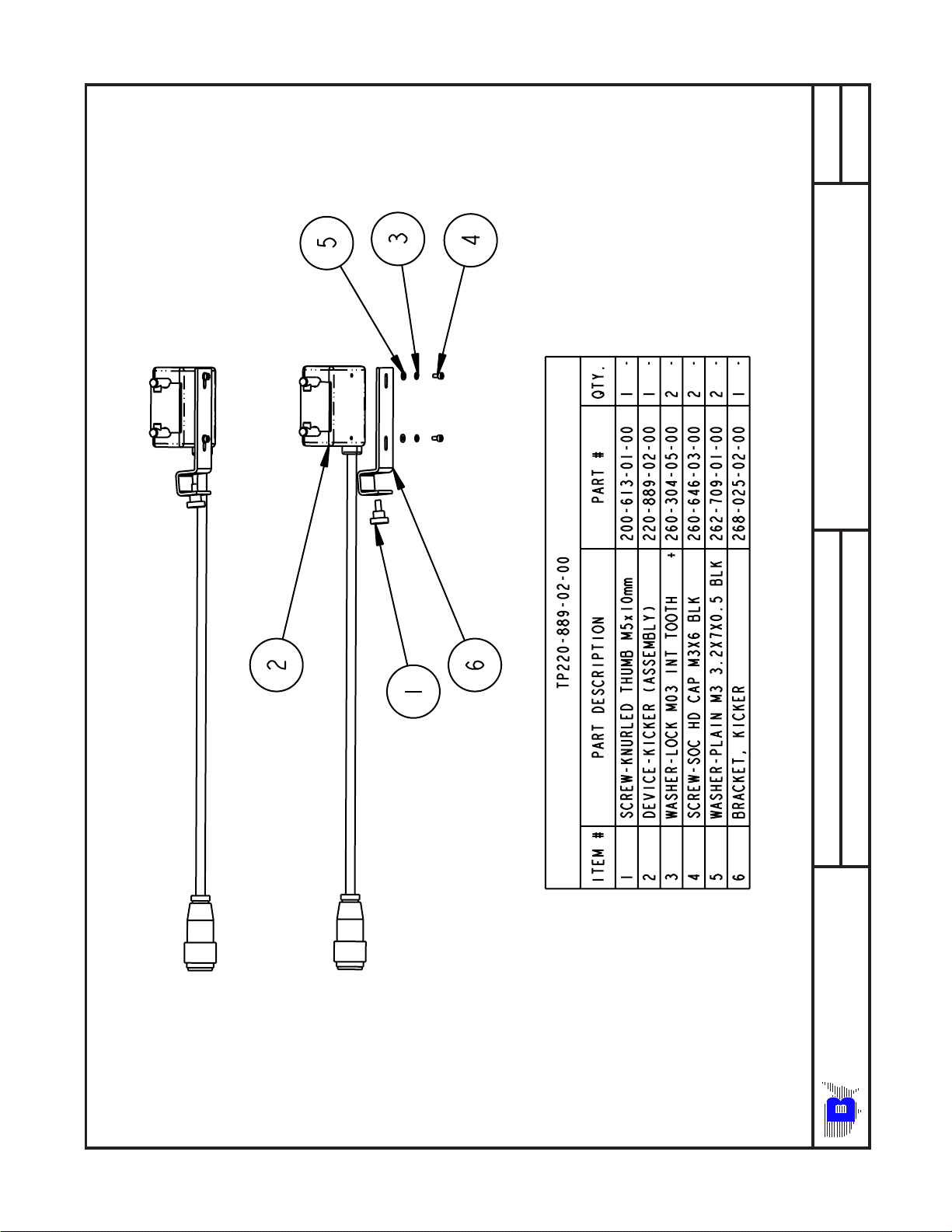
If the kicker device is not assembled to the bracket, do so
with the supplied hardware per drawing TP220-889-02-00
of this manual.
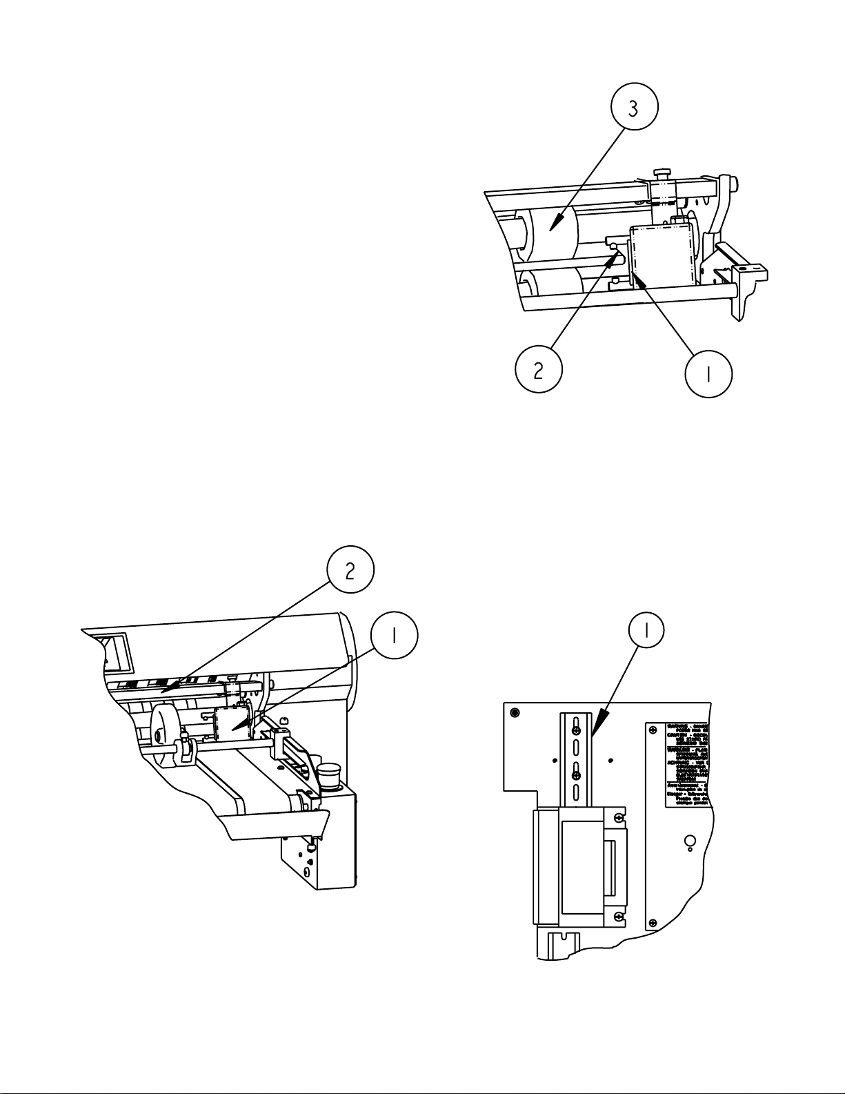
Install the assembled kicker device(Figure 1-1) on the
square slitter shaft accessory spreader bar(Figure 1-2).
The location of the kicker unit is dependent on the type
and size of fold that is being made.
Figure 2
After locating the kicker unit, plug the connector into the
1X12 connector located on the side of the main control
panel.
Open the door of the main control panel and find the DIN
rail located in the upper left hand corner above the blue
power transformer. Remove the hardware that attaches
the rail to the box and rotate the rail 90 degrees(Figure 3-
1).
Figure 1
The location of the kicker unit, along the tie bar, is set so
that the striker plate(Figure 2-1) of the plunger is
approximately 1/8 from the right edge of the
stock(Figure 2-2) as it exits the slitter assembly pullout
tires(Figure 2-3).
Figure 3
TP10324A PAGE 4
Page 5
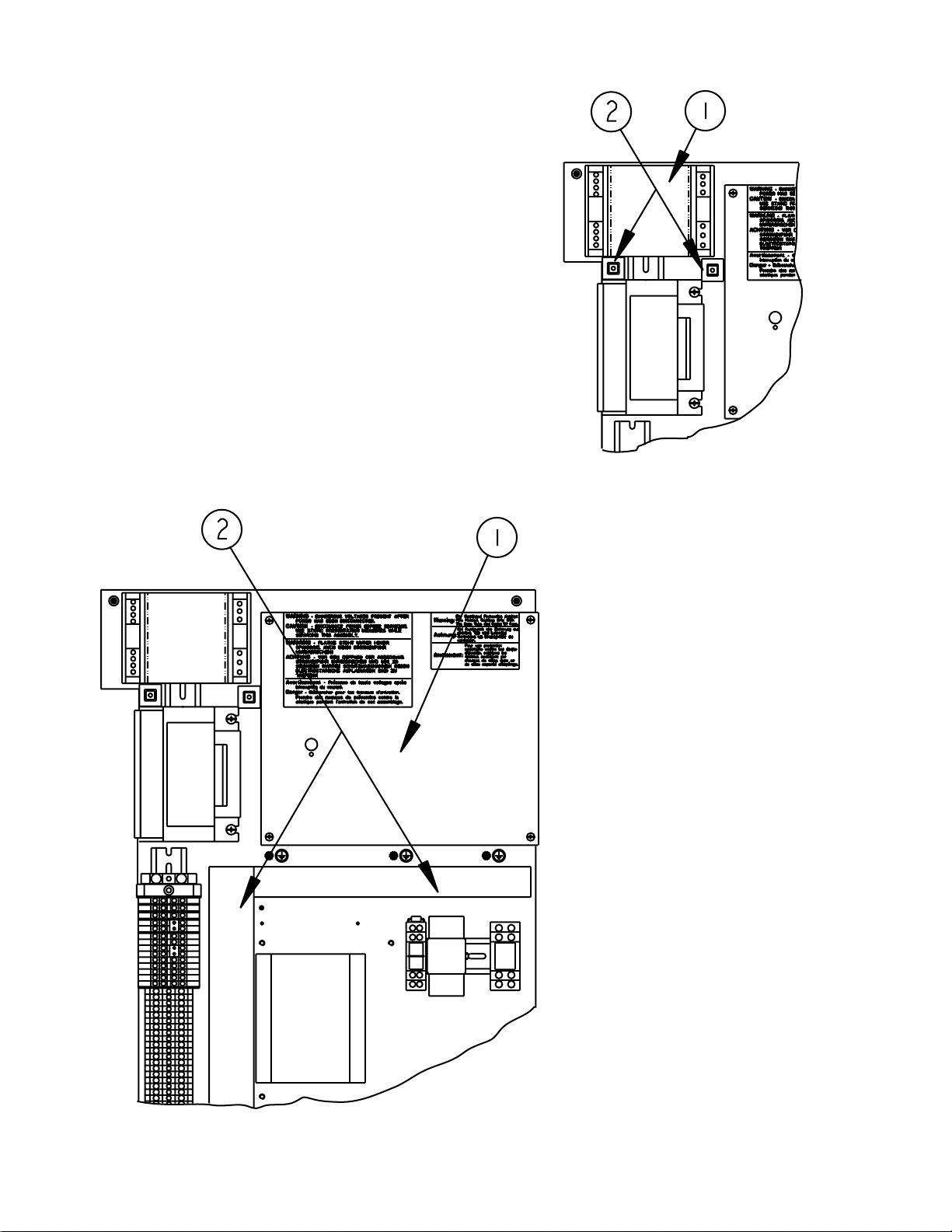
Install the kicker module, A20(Figure 4-1), on the DIN rail
in the upper left corner of the main electrical enclosure, as
shown. Place the two cable tie anchors in the approximate location show in Figure 4-2.
Remove the protective plexiglass cover(Figure 5-1) that
covers the main circuit board. Also remove the two
wireway covers(Figure 5-2).
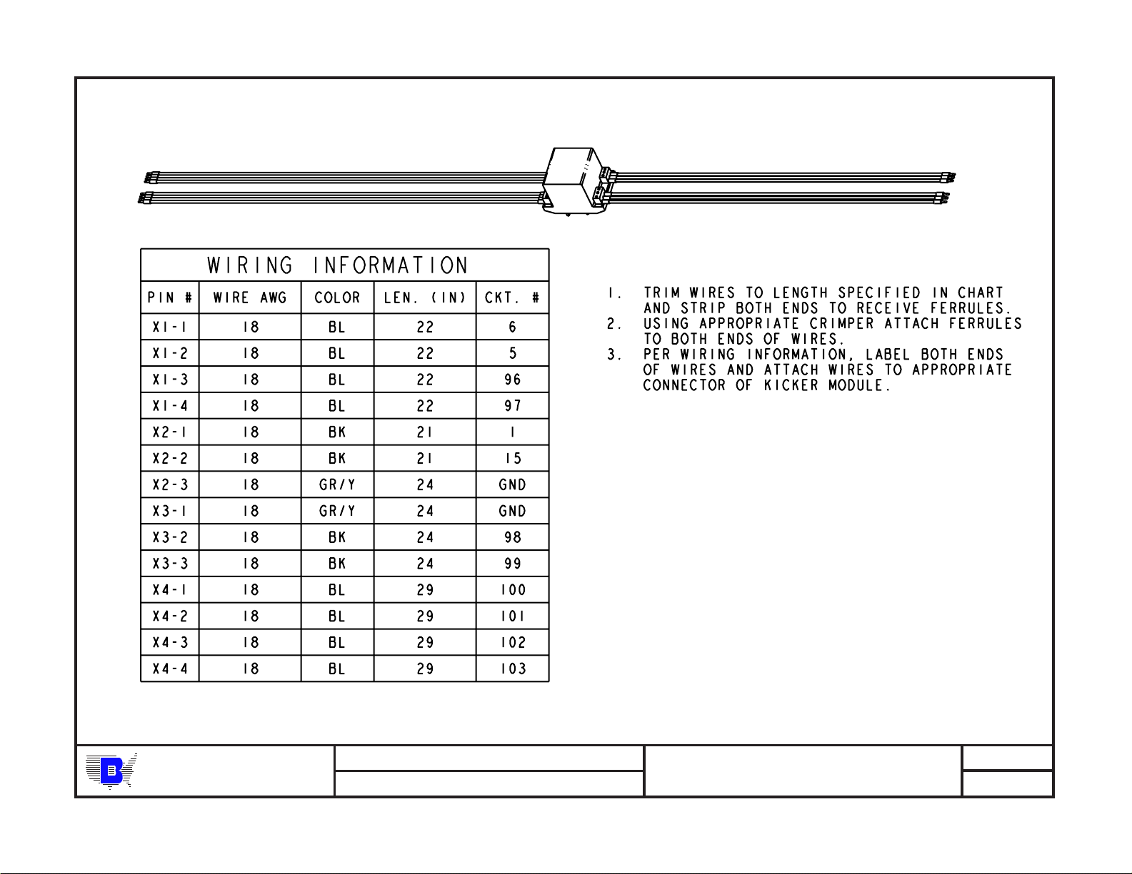
Install the wires from the kicker module, A20, per the
wiring instructions of Figure 6. After installation of wires,
replace plexiglass cover and two wireway covers. Cable
tie wire bundle to anchors and cable tie the rest of new
wiring to existing wires.
Close main electrical enclosure and reapply power to the
folder.
Figure 4
Figure 5
PAGE 5 TP10324A
Page 6
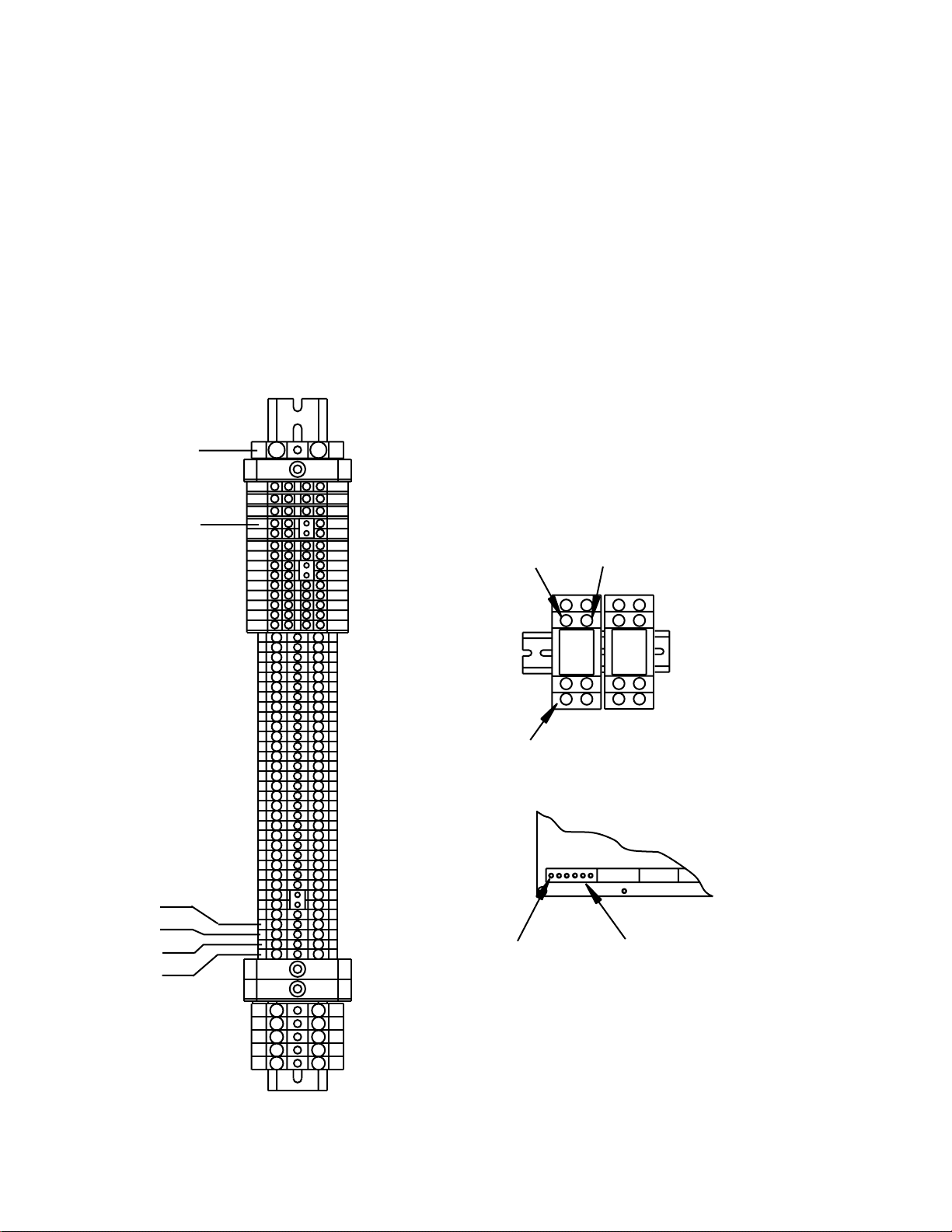
CKT NO. COLOR FROM TO
5 BL A20-X1-2 A1-2X25-4
6 BL A20-X1-1 A1-2X25-3
1 BK A20-X2-1 TB1-1
15 BK A20-X2-2 TB1-15
GND GR/Y A20-X2-3 TB1-PE
GND GR/Y A20-X3-1 TB1-PE
98 BK A20-X3-2 K3-4
99 BK A20-X3-3 K3-1
96 BL A20-X1-3 A1-2X25-5
97 BL A20-X1-4 A1-2X25-6
100 BL A20-X4-1 TB1-100
101 BL A20-X4-2 TB1-101
102 BL A20-X4-3 TB1-102
103 BL A20-X4-4 TB1-103
TB1-PE
F17
TB1-1
TB1-100
TB1-101
TB1-102
TB1-103
F15
F16
Pin 4
K3
Pin 1
Pin 1
A1-2x25
Figure 6
TP10324A PAGE 6
Page 7
25 2824 28 12 10 1417
1 29 30 31 32 33
56
4
3
2
1
BAUMFOLDER
CORPORATION
7
8
9
10
36
9 13 11 16 26 27 22 23 4 5 7 615 3
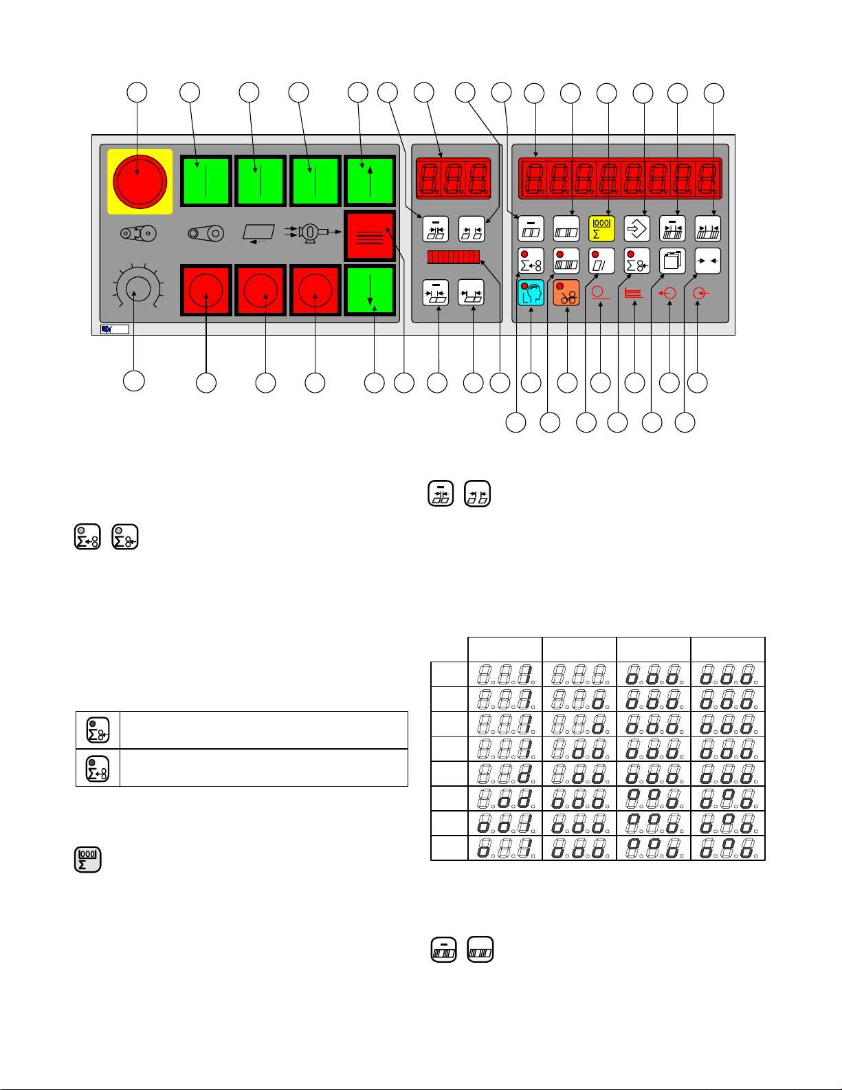
2.0 KICKER FUNCTION SETUP
2.1 Select Count Source
The Output Count and Input Count keys select between
count at delivery and feeder, respectively. One key LED will
always be lit in Counter Setup to show the current count
source, see below. Chasing LEDs will activate in the small
display signifying the start setup mode. The next sheet fed
through will be timed from leading edge to trailing edge and
the delay time will be set to one half the sheet time. Please
note this must be redone if the delivery speed is changed.
Select the Output Count button #18.
The batching count source will be the feeder
photoeye.
The batching count source will be whatever is
connected as the del ivery photoey e.
2.2 Counter Setup Mode
+
+
18 19 20 21 34 35
+
h
+
0
Change Batching Type
+
The minus and plus buttons move through a list of four
output devices. The chosen type is then activated when the
batch down-count goes to zero. Select the MKE Table column
to kick the last sheet for the batching type setting.
The output types are represented by animated symbols.
The sequence of frames for the animations is shown below.
Feed Interruption Speed Up Table MKE Table Kicker
Frame
1
Frame
2
Frame
3
Frame
4
Frame
5
Frame
6
Frame
7
Frame
8
Future
Feature
Pushing this key puts the counter in counter setup mode.
Counter setup mode is used to prepare the controller to
run a job. The large display (1) shows the batch preset on the
left-hand side and the batching output time on the right hand
side. The decimal points in the large display (1) will move from
side to side to indicate that a parameter may be changed. The
small display (2) shows the batching type. The suction length
display (3) is active.
PAGE 7 TP10324A
Output Type Animations
Batch Preset Adjustment
+
These buttons cause the batch preset value to increment or
decrement. The preset will be reloaded after the user leaves
the setup mode only if the value has been changed.
Page 8

Batching Time Adjustment
+
The batching time adjustments allow the user to select the
time duration associated with the currently selected output
type. Two output types and times are available.
1. Feed interrupt has a range of 0.0 to 9.9 seconds.
2. Speed-up Table has a range of 0.00 to 5.00 seconds.
Set the range at approximately 0.5.
2.3 Make Ready Mode
This key places the controller in the make ready mode.
The key LED goes on. In this mode the folder will only feed
single sheets and a batching output is issued for every two
sheets fed. This allows the operator to easily set up the
batching time.
Press the make ready button.
Press the sheet feed button, one sheet will be fed. The
system will measure the sheet and automatically set some
tiking parameters.
After each second sheet the Kicker will activate. Adjust
the Kicker timing by changing thebatching time in the counter
setup mode. This will achieve the desired offset (index) for
the batch point.
Press the Make Ready button (#23). Its LED should go
out informing you that the system is ready for production.
TP10324A PAGE 8
Page 9
1 2
REV:
SHEET OF
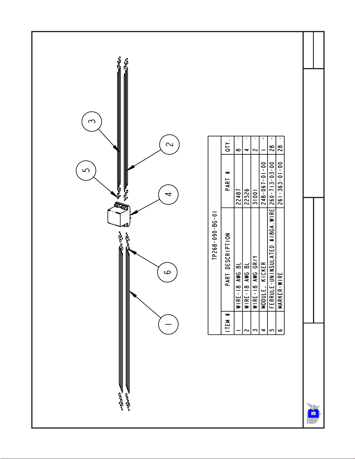
TP268-090-BG-01
ASSEMBLY NUMBER:
2020 KICKER MODULE ASSEMBLY
DESCRIPTION:
UNIT NAME:
BA UMFOLDER CORPORATION
PAGE 9 TP10324A
2020 KICKER KIT
Page 10
TP10324A PAGE 10
BA UMFOLDER CORPORATION
DESCRIPTION:
UNIT NAME:
2020 KICKER MODULE ASSEMBLY
2020 KICKER KIT
ASSEMBLY NUMBER:
TP268-090-BG-01
REV:
SHEET OF
2 2
Page 11
1 1
REV:
SHEET OF
TP220-889-02-00
ASSEMBLY NUMBER:
2020 KICKER DEVICE ASSEMBLY
DESCRIPTION:
UNIT NAME:
BA UMFOLDER CORPORATION
PAGE 11 TP10324A
2020 KICKER KIT
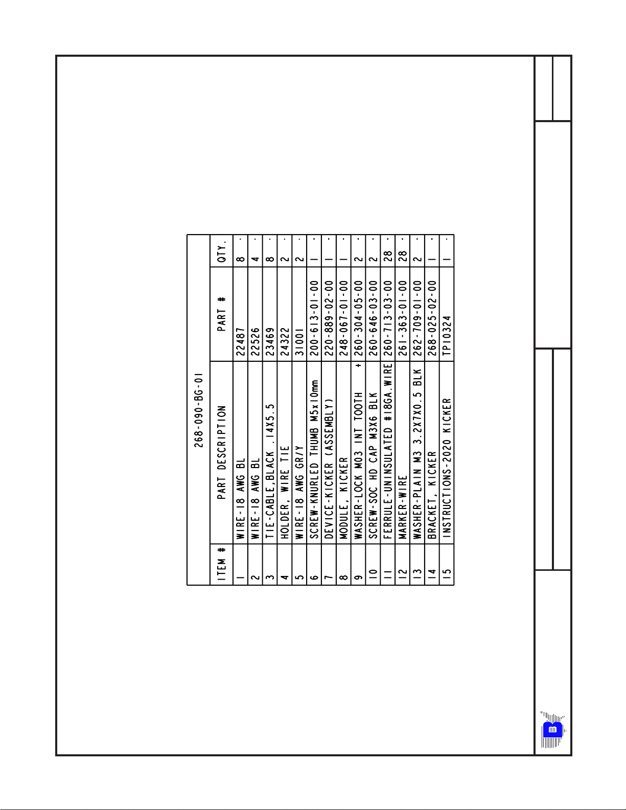
Page 12
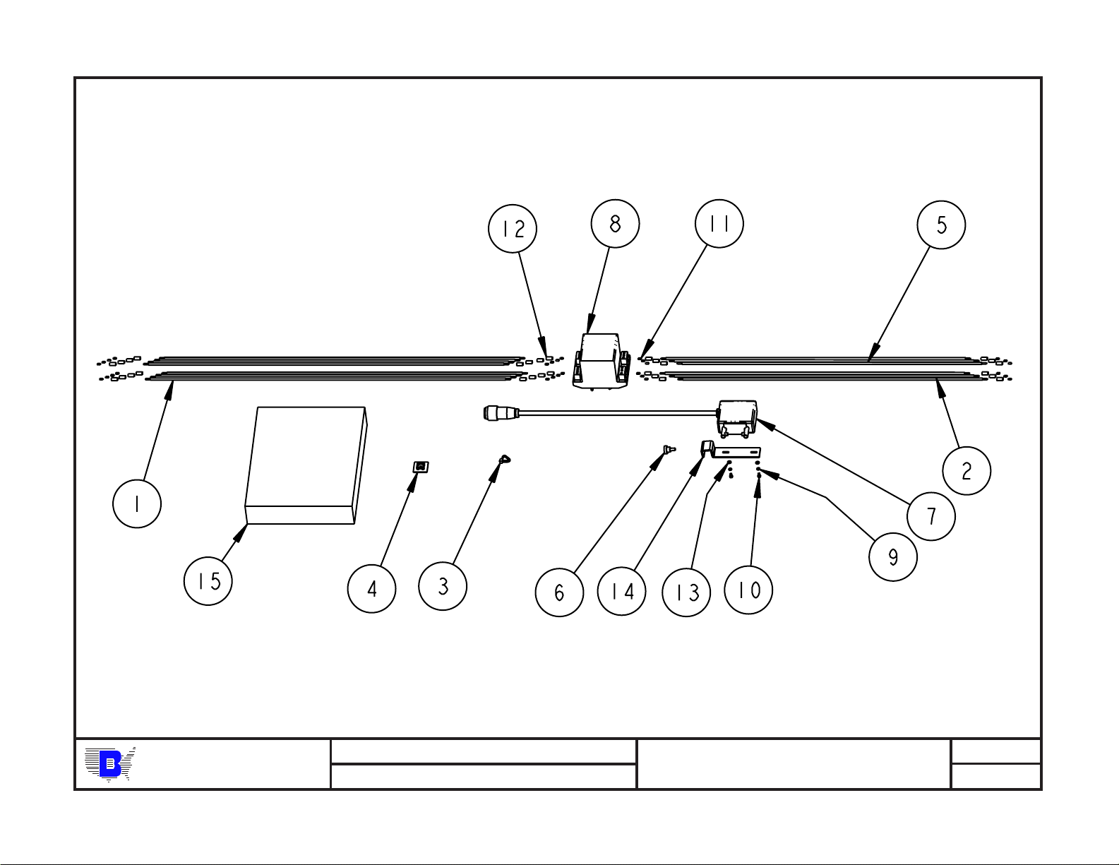
TP10324A PAGE 12
BA UMFOLDER CORPORATION
DESCRIPTION:
UNIT NAME:
2020 KICKER KIT ASSEMBLY
2020 KICKER KIT
ASSEMBLY NUMBER:
268-090-BG-01
REV:
SHEET OF
1 2
Page 13
2 2
REV:
SHEET OF
268-090-BG-01
ASSEMBLY NUMBER:
2020 KICKER KIT ASSEMBLY
DESCRIPTION:
UNIT NAME:
BA UMFOLDER CORPORATION
PAGE 13 TP10324A
2020 KICKER KIT
Page 14

TP10324A PAGE 14
BA UMFOLDER CORPORATION
DESCRIPTION:
UNIT NAME:
2020 KICKER KIT SCHEMATIC
2020 KICKER KIT
ASSEMBLY NUMBER:
267-385-00-11
REV:
1 1
SHEET OF
Page 15
Baumfolder has authorized dealers located throughout the United States.
Call toll free, 1-800/543-6107 for parts or the
number of your nearest authorized dealer.
BAUMFOLDER
C O R P O R A T I O N
Quality Bindery Equipment Since 1917
1660 Campbell Road
Sidney, Ohio 45365-0728
Phone: 937/492-1281 or 800/543-6107
Fax: 800/452-0947
Internet: www.baumfolder.com
E-mail: baum@bright.net
PAGE 15 TP10324A
 Loading...