

Page 1

TP10497
IFOLD
SERVICE
MANUAL
Page 2

TABLE OF CONTENCE
TP10497
IFOLD ELECTRICAL INSTALATION……......................PAGE 3
IFOLD MACHINE CONFIGURATION….........................PAGE 12
IFOLD STARTUP PROCEDURES………................…...PAGE 17
IFOLD SHUTDOWN PROCEDURES…………..............PAGE 17
SCREEN MAINTAINENCE………………...................….PAGE 17
WARRANTY NOTE……………………………….............PAGE 17
MAIN SCREEN HELP…………………........................…PAGE 18
FOLD SELECT HELP………………………….................PAGE 21
PAPER SELECT HELP……………………................…..PAGE 22
SUMMARY PAGE HELP………………………................PAGE 25
ADJUST PARALLEL HELP……………….......................PAGE 29
MAINTENANCE HELP…………………...............………PAGE 32
JOB CALCULATOR HELP…………………............…….PAGE 33
IFOLD PARTS MANUAL……………………............……PAGE 34
IFOLD SCHEMATIC……………………………….......….PAGE 47
Page 3

Page 1 of 45
TP10497
1
I-FOLD ELECTRICAL INSTALLATION
location (See Page 33). Note: Before tightening the (4) socket head screws, locate display mount so that a gap
between the top of the register frame and the display mount is at maximum clearance, so that the register guard
can be re-installed.
1. WARNING: Power MUST BE DISCONNECTED from the machine before starting this procedure.
2. Remove the back feeder, parallel & register guards.
3. Install I-fold display mount (See Assy. Drawing FK2001426) onto register frame as shown in I-fold display mounting
Figure 1
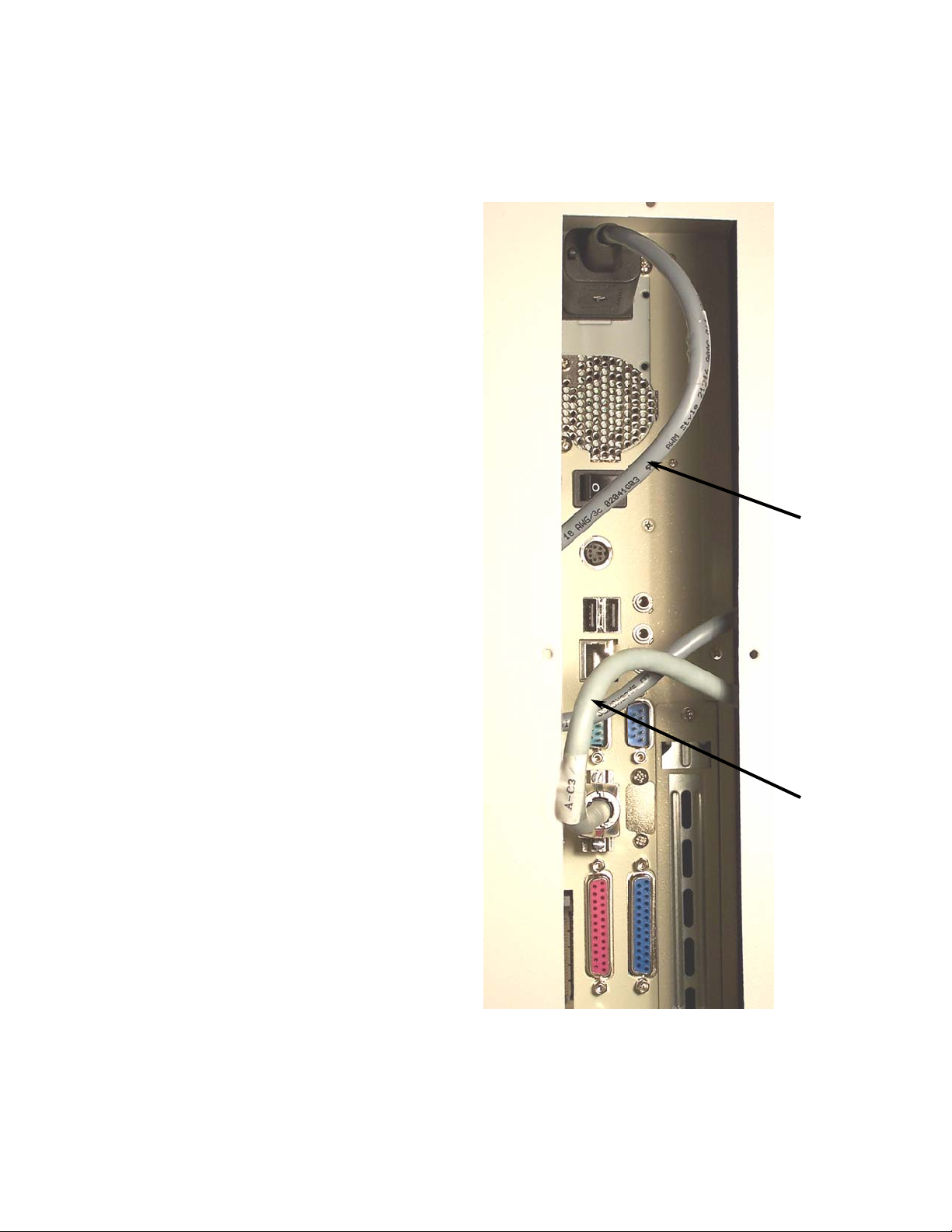
COM 2 Power Switch Power Socket
Page 4
2
Page 2 of 45
TP10497
receptacle “COM 2”, see Figure 2.
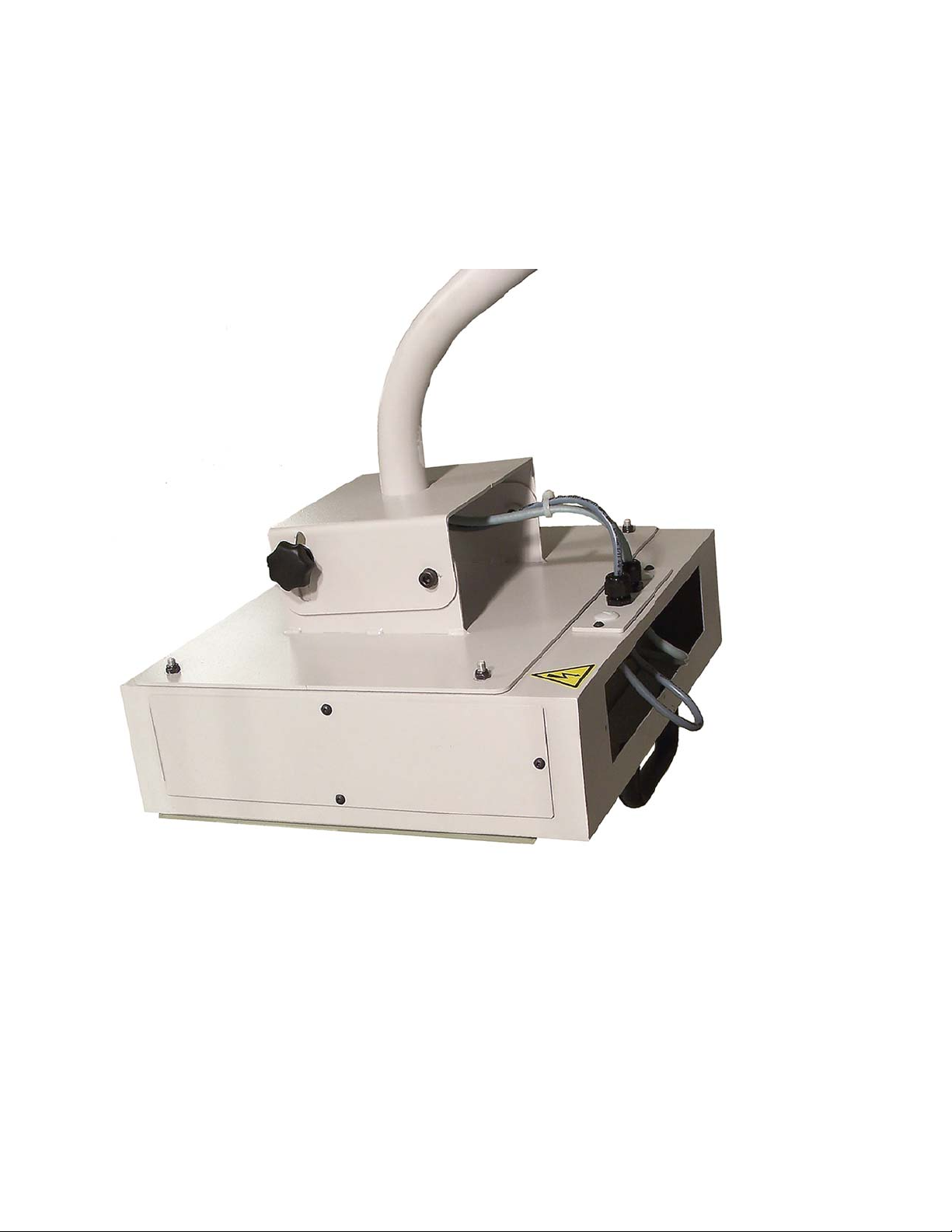
4. Install mounting arm into display mount.
5. Mount computer and enclosure onto mounting arm as shown in figure 3.
6. Remove Bottom cover plate from I-fold computer enclosure, to expose computer’s connectors, see Figure 1.
7. Install power cable FK201500 into computers power socket. Install communication cable FK2001501 into computer
computer’s enclosure, until both cables have a 3” to 4” service loop on the cable between the connectors and the
strain relief’s. Tighten outer strain relief nut to hold cables securely, see Figure 3.
8. Run both the power and communication cable through a cable strain relief located in a plate on the back side of the
the goose neck mounting arm tube and pull cables out the bottom of the mounting block, as shown in Figure 3.
9. Run both power and communication cable up into the hole of the enclosure mounting bracket and down through
Figure 2
Communication Cable Power Cable
Page 5
3
Page 3 of 45
TP10497
Figure 3
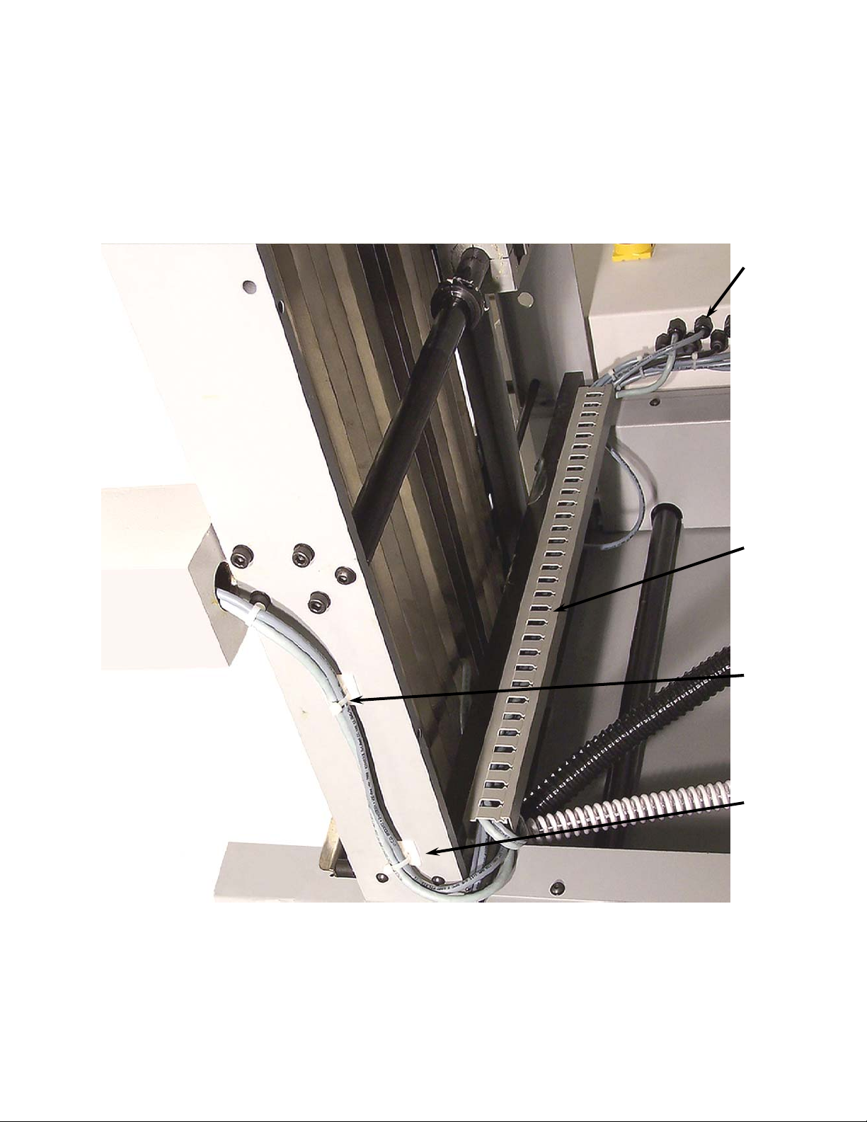
through the wire channel across the register. Remove two hole plugs in the back of the electrical enclosure and
install two cable strain reliefs. Run the two cables through the strain reliefs. Install folder guarding and wire
channel cover. Tighten the two strain relies to secure the cables.
10. Mount the 2 cable anchors, as shown in Figure 4. Mount cables with wire ties to the anchors as shown, run
Page 6
4
Page 4 of 45
TP10497
Figure 4
Cable Anchor Wire Tie Wire Channel Strain Reliefs
Page 7
Page 5 of 45
TP10497
5
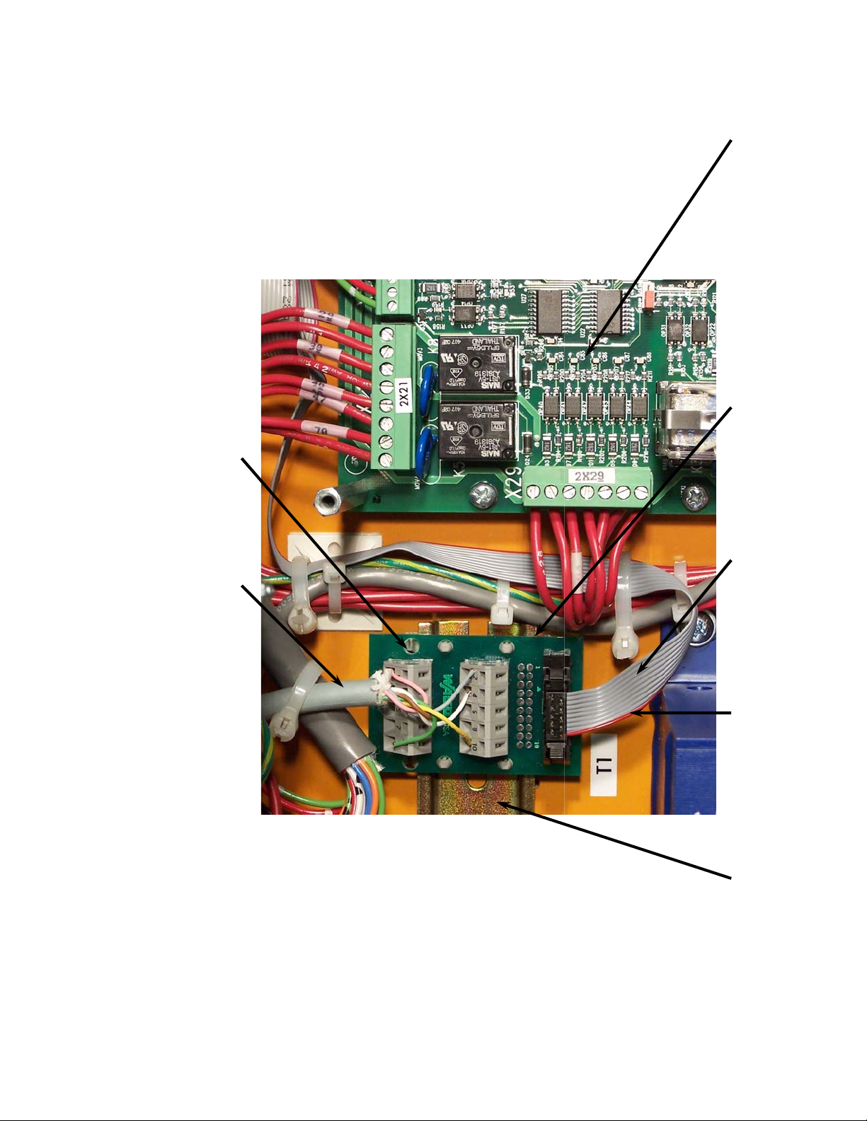
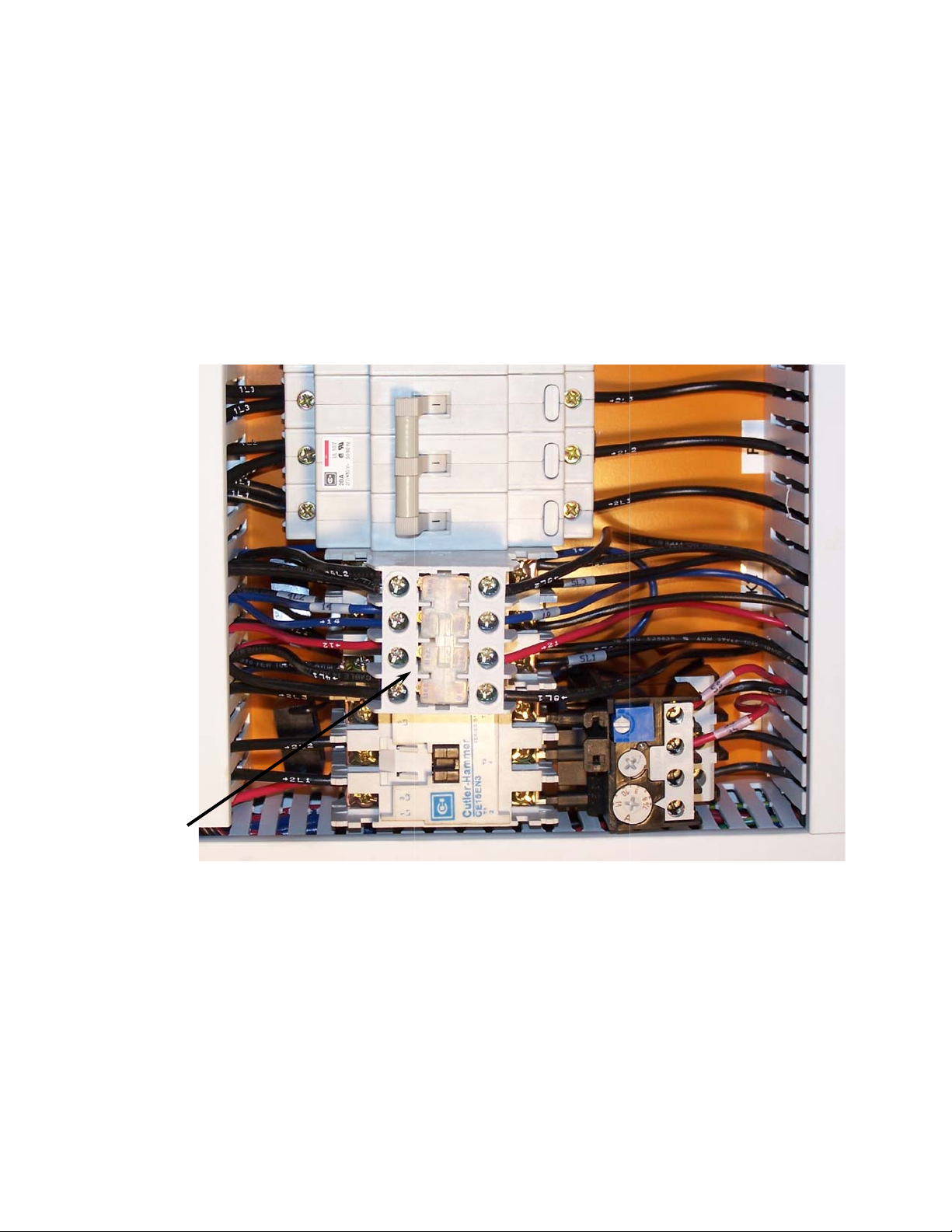
Run the communication cable to the top of the communication board and will wire into the two rows of terminals.
Add an extra 2” to 3” of cable, and then cut cable to that length. Strip back 4” of cable jacket and shielding to
expose conductors. Cut pink, brown & green conductors 1” shorter than the other three conductors. Strip
approximately 5/16” of wire insulation from each conductor. Wire communication cable into the communication
board terminal block as shown in figure 6.
Din Rail Cable Orientation Stripe Ribbon Cable Communication Board DCT500 Board
11. The communication board will sit on the right side of din rail that sits above the transformer, as shown in Figure 5.
Figure 5 Communication Cable Terminal Block
Page 8
12349
Pink
X27
Page 6 of 45
TP10497
Ribbon
Cable
Board
DCT500
Communication
6
Terminal Block
Gray
Figure 6
Brown
White
Cable
10
Yellow
Green
Communication
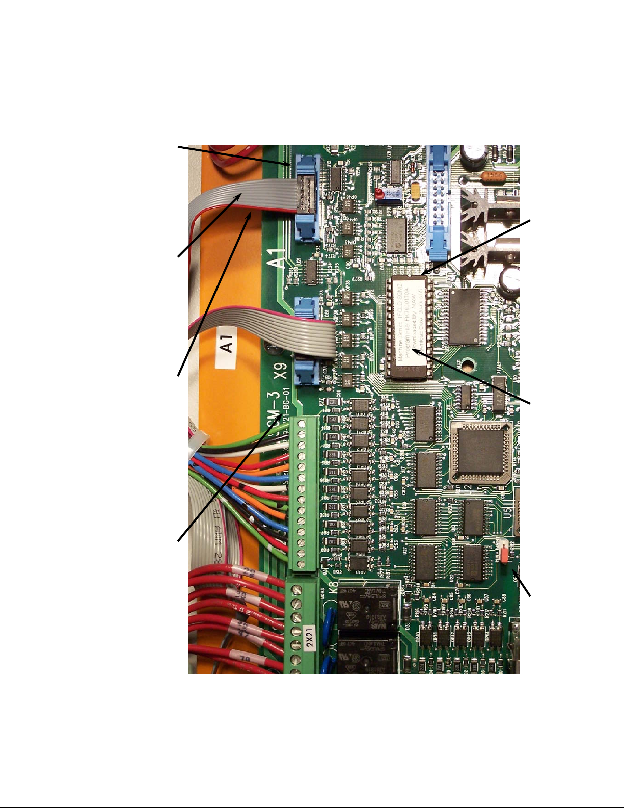
the ribbon cable, this must be on the left side of connector as shown. The connector can be installed backwards.
Run cable and connect to the X27 connector on the DTC500 board, see Figure 9. Note orientation stripe on the
ribbon cable, this must be on the left side of the X27 connector as shown. The connector can be installed
backwards. Secure the ribbon cable with wire ties, NOTE: do not over tighten or crush the ribbon cable with the
wire ties.
12. Add ribbon cable. Connect one end to the communication board as shown in Figure 5. Note orientation stripe on
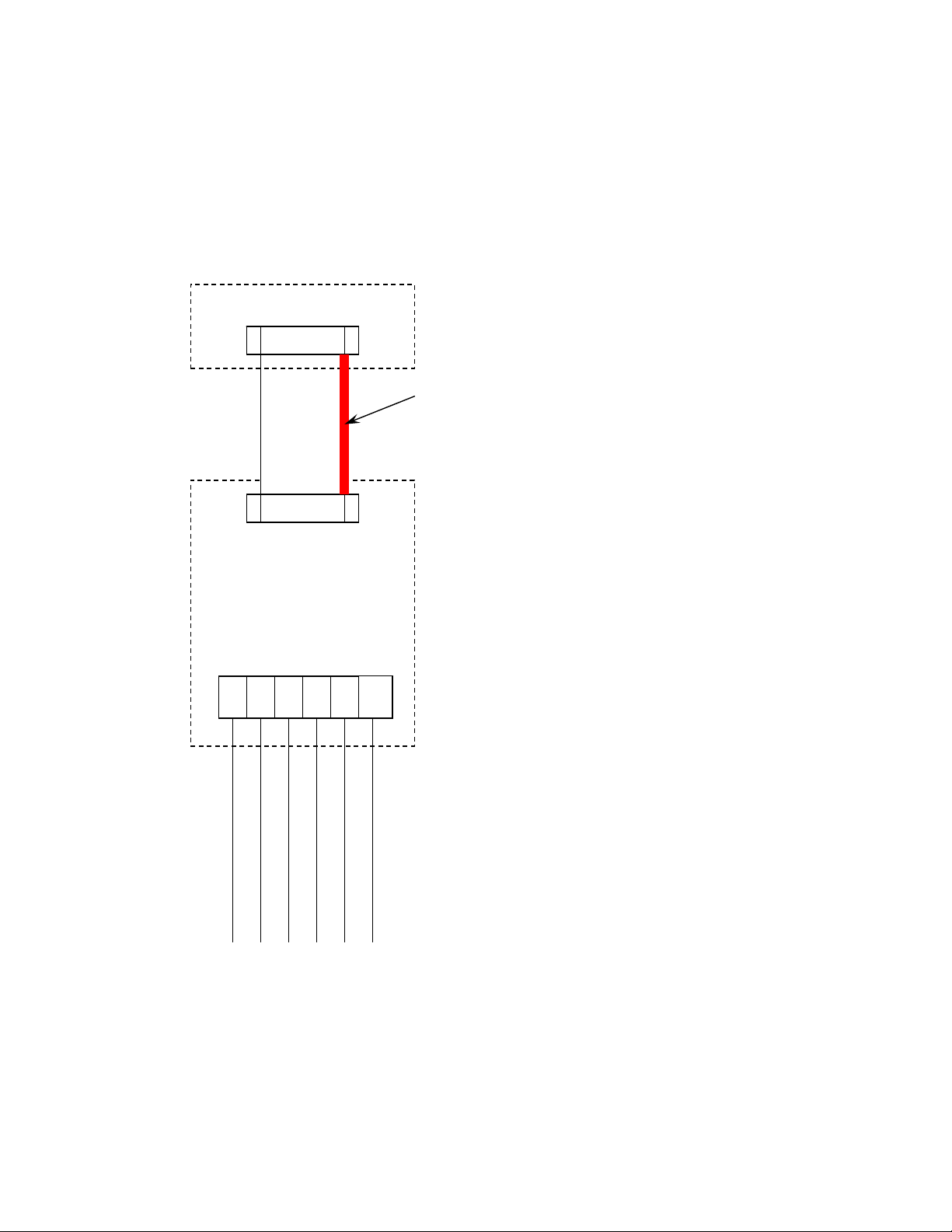
must be tied together with a tie pin, this will insure that both fuse holders will open at the same time. Label fuse
13. Add new fuse blocks to the din rail to the right of the existing fuse blocks as shown in Figure 7, The fuse blocks
blocks as A-F1 and A-F2. NOTE: DO NOT INSTALL FUSES AT THIS TIME. Run I-fold power cable between
transformer and the terminal blocks and into the wire channel. Run cable to the bottom side of fuses. Add an
extra 2” to 3” of cable, and then cut cable to that length. Strip back approximately 8” of cable jacket. Strip
approximately 5/16” of wire insulation from each conductor. Add ring terminal to the green \ yellow conductor
and mount to ground lug shown in Figure 7. Wire conductor 1 to bottom of fuse block A-F1 and wire conductor 2
to bottom of fuse block A-F2.
Orientation Stripe
Page 9
7
Page 7 of 45
TP10497
Figure 7 A-F1 4L1 A-F2 4L2
Fuse Block Ground Lug
both ends. Label one conductor 4L1 and the other conductor 4L2 at both ends. Wire 4L1 to the top of fuse block
A-F1, and wire 4L2 to the top of fuse block A-F2, as shown in Figure 7.
14. Take wire and cut into two equal lengths. Strip approximately 5/16” of wire insulation from each conductor at
Page 10
8
Page 8 of 45
TP10497
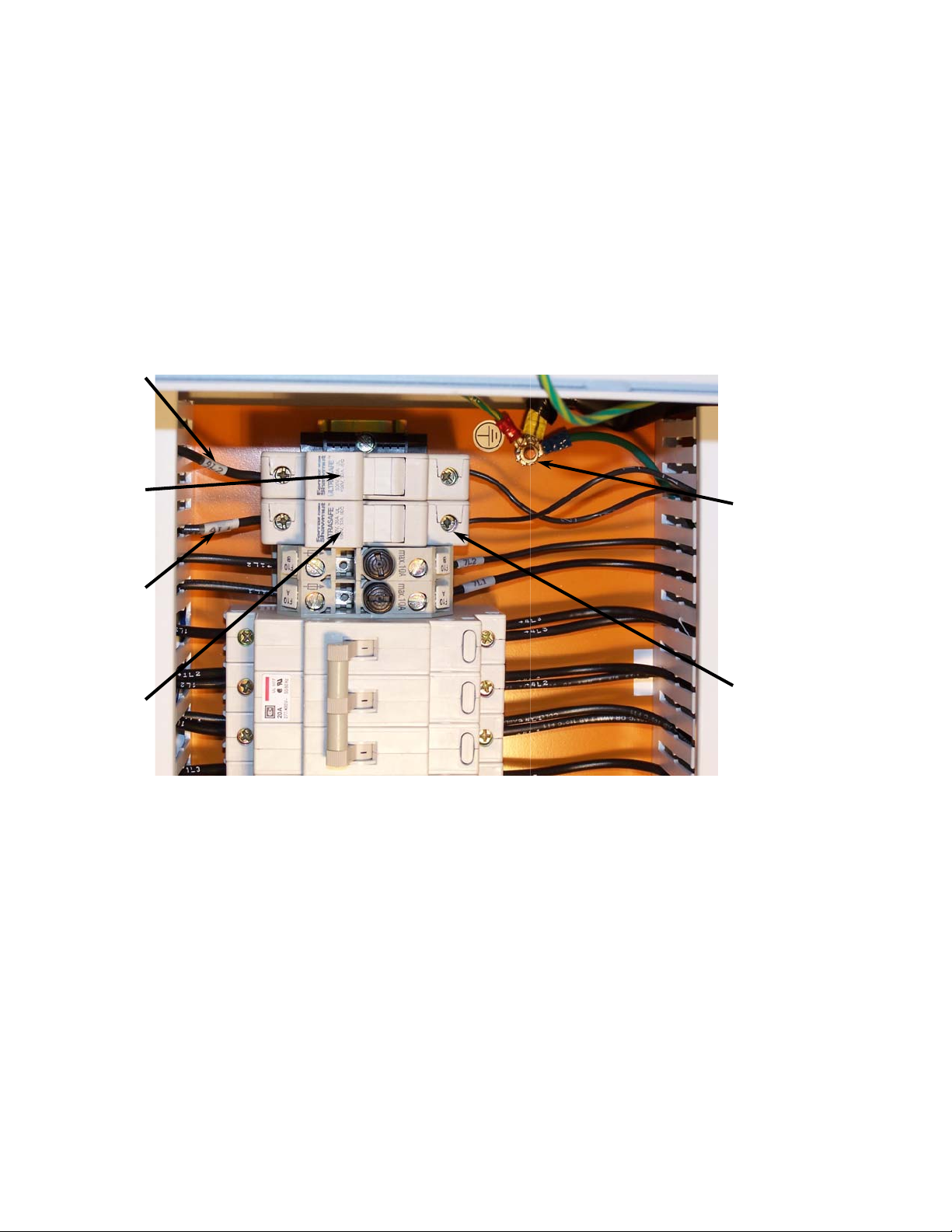
is a 15” or 18” model or to K2-63 if folder is a 20” model, as shown in Figure 8.
15. Run wire 4L1 to K2-53 if folder is a 15” or 18” model or to K2-53 if folder is a 20” model. Run 4L2 toK2-83 if folder
Figure 8 K2
Page 11
Page 9 of 45
TP10497
9
chip at both ends and out of the U6 socket. Do not handle the chip by the legs, only by the sides of the chip. Note
the orientation of the chip notch, the new chip must be installed in the same direction. Care must be taken not to
touch the legs of the chip. Carefully install new chip into the U6 socket.
16. Cleanup wiring and reinstall all wire channel covers that were removed.
17. Replace DCT500 software chip, shown in Figure 9. Carefully do this by using a small screw driver and lifting the
Figure 9 DCT500 Board Orientation Stripe Ribbon Cable X27 Connector
Run/Maintenance jumper Software chip Notch end
Page 12
pins; this will place the machine
Page 10 of 45
TP10497
rd
and 3
nd
pins) to the 2
nd
and 2
st
10
in maintenance mode at power up. See jumper location in Figure 9.
18. Move the run/main jumper (currently on the 1
THIS TIME. Turn on main power switch.
19. Reconnect power to the machine, NOTE: I-FOLD COMPUTER FUSES A-F1 and A-F2 ARE NOT INSTALLED AT
message will display in display 2. Then the new software version will display in display 2, “dct 9.9.b”. Then the
machine will switch to maintenance mode, display will display ether “oFF” or “dSP” and display 2 will display the
machine model i.e. (P-2020).
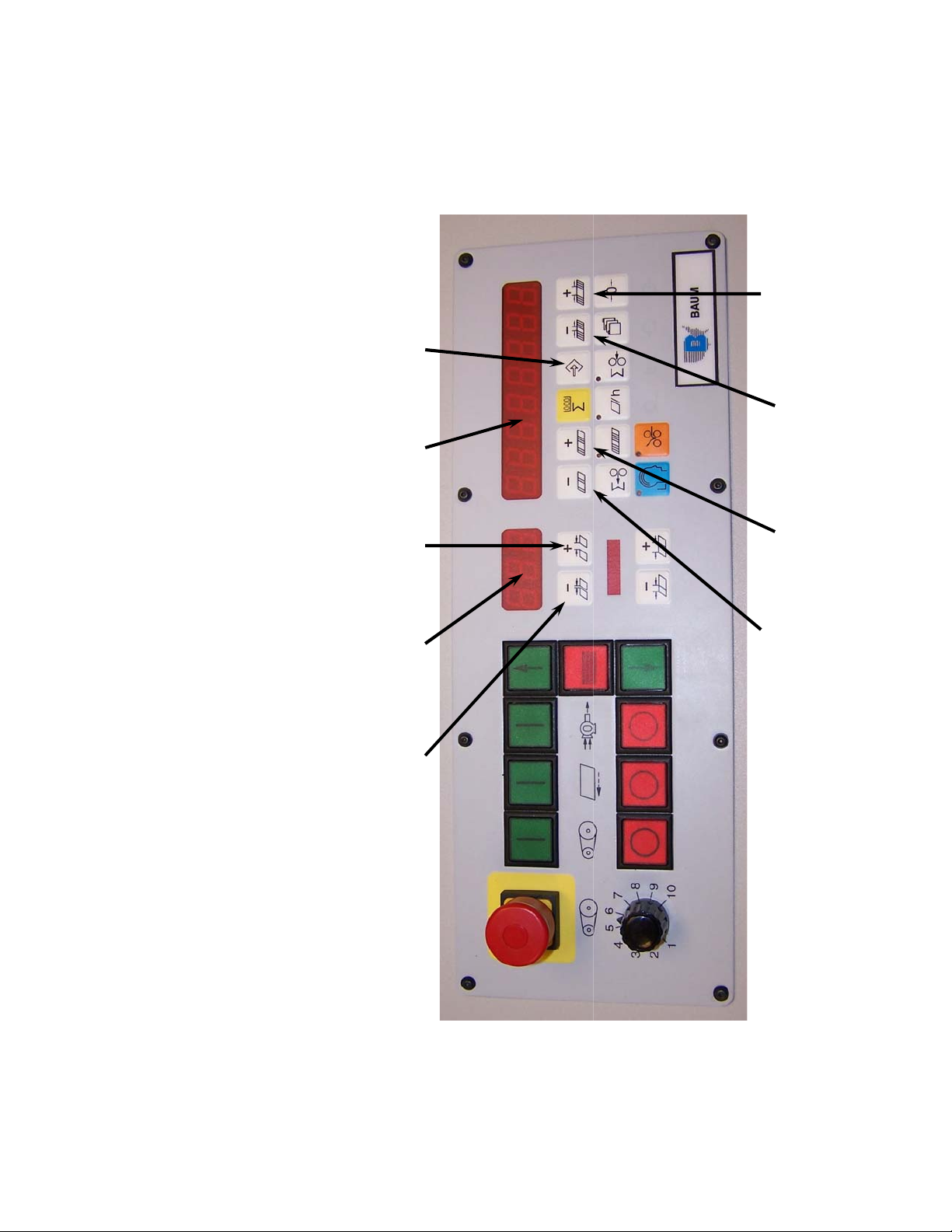
20. Folder will wake up in maintenance mode. Both displays will light up with “8” in each segment. Then a diagnostic
modes by pressing button 1, or button 2, until “nEt” is displayed.
21. Set Serial Port operating mode. Note display 1, Figure 10, this display needs to display “nEt”. To toggle between
Figure 10 Button 1 Display 1 Button 2 Display 2 Button 3
Button 4 Button 5 Button 6 Button 7
Page 13

nd
Page 11 of 45
TP10497
11
pins; this will place the machine back in run mode at power up. See jumper
nd
and 2
st
pins) back to the 1
rd
BAUMFOLDER CORP.
ATTN. MARK WALKER
1660 Campbell Road
Sidney, Ohio 45365
button 4 and button 5 to change the value of display 1. By pressing button 5 the value increases, set value to
“A03”. A value of “0” should now be displayed in display 2. Use button 6 and button to change its value to “1”.
Next value “A04” must be displayed in display 1, use button 5. The value of A04 is displayed in display 2 and must
be change to “nEt 1”. Press button 6 or 7 to change the value. Press button 3 times to exit program mode.
22. Go to the advance settings by pressing button 3, Figure 10. Value A00 should now be displayed in display 1. Use
across the top of the new fuse blocks A-F1 and A-F2. The reading should be between 200 to 244 Volts. If not, go
back and troubleshoot power circuit, before fuses are installed.
23. Check the voltage to the I-fold computer by taking a voltmeter, setting it to VOLTS AC and look at the voltage
and 3
location in Figure 9.
24. Power down the machine by switching off main power switch. Move the run/main jumper (currently on the 2
and close up enclosure.
25. Install .5 amp fuses into fuse blocks A-F1 and A-F2. Reinstall cover over the DCT500 board. Cleanup enclosure
26. Turn on main power switch and let the machine wake up normally.
display in display 1. Use button 4, or button 5, to display “P22” in display 1, Display 2 should now read “Addr 1”.
Use button 4, or button 5. to change display 1 to read “P24”, Display 2 will read “nEt 0”. Use button 6, or button
7, to change display 2 so it reads as “nEt 1”. Press button 1 once then button 3 once to leave setup mode.
27. Go into the machine setup mode by pressing button 3, see Figure 9. Use button 1, or button 2, to get “P20” to
28. If I-fold computer is not up at this time check power switch on the computer, it must be switched on, see Figure 1.
Baumfolder for reprogramming.
29. Place the removed chip, from instruction 13 back into the box the new chip came in and please send it back to
Page 14

Page 12 of 45
TP10497
instructions
For service technicians use only
ifold machine configuration
Page 15

Page 13 of 45
TP10497
The first time ifold is powered up the Machine
Configuration button will appear on the start up
screen. Touch this button to configure for your
machine.
Page 16

This should be set from the factory.
Page 14 of 45
TP10497
0 = Autoset
1 = 2015
2 = 2020 pile
3 = 2020 continuous
4 = 1526 or 1530
This will only appear if the machine type is
4. It should be set from the factory to the
width of your machine.
Once the number of plates in the Parallel
are set these boxes will disappear. Verify
the settings are correct before setting the
number of plates in the parallel.
Touch this box to tell Ifold how many plates
you have in the parallel unit. It will
increment thru 0 2 3 4 6 each time you touch
this box.
Touch this box to tell Ifold how many plates you
have in the 8page unit. It will increment thru 0 2
3 4 6 each time you touch this box. If you do not
have an 8page unit leave it set to 0
Touch this box to tell Ifold how many plates you
have in the 16page unit. It will increment thru 0
2 3 4 6 each time you touch this box. If you do
not have a 16page unit leave it set to 0
Once you have completed the configuration
touch this button to go to the main page.
Page 17

Touch this box to tell Ifold if you have the
Page 15 of 45
TP10497
optional Gatefold plate. It will toggle between
yes and no each time it is touched.
Touch this box to tell Ifold if you want to display
the optional exit sensor count in place of the
standard infeed count. It will toggle between yes
and no each time it is touched.
Touch this box to tell Ifold if you are using the
standard hang on stacker. It will toggle between
yes and no each time it is touched. This is very
important if this is an Autoset.
Touch this box to tell Ifold if you have the
optional Presser Stacker. It will toggle between
yes and no each time it is touched.
Touch this box to shut down Ifold but not the
computer. This should only be used when
DO NOT TOUCH THIS BUTTON. This button
is for factory use only.
updating the program
Page 18

This will bring up a keypad asking you to enter
Page 16 of 45
TP10497
the password. Enter the password 4921281 then
touch the enter button.
Once in the Maintenance screen touch the
Machine Set-up button.
You can get back into the Machine
Configuration screen at anytime by going to the
main page then touching the Maintenance button
Page 19

Page 17 of 45
TP10497
Start up procedures
The I-Fold software should start-up automatically when the
machine is turned on. If for any reason it does not start up properly
cycle power to the machine. If the I-Fold software still will not start up
contact your local dealer for support.
Shut down procedures
It is very important to shut down the I-Fold properly before
turning off the machine. Before powering down the machine press the
button to start the power down procedure. A pop up box will
appear asking if you are sure you want to power down. Press OK.
From this point the power down is automatic. Once the screen reads it
is OK to turn off your computer you can shut down the machine.
Cleaning Touch Screen computer
It is very important to shut down the I-Fold computer before
cleaning the computer screen. Use a CRT screen cleaner ONLY on the
interface touch screen.
Warranty Note
WARNING – Damage to the computer screen will occur if
any instrument other than the operator’s finger is used to navigate
the I-Fold screens. NOTE: Warranty on the computer will be void
if this is found to be the case for computer failure.
Page 20
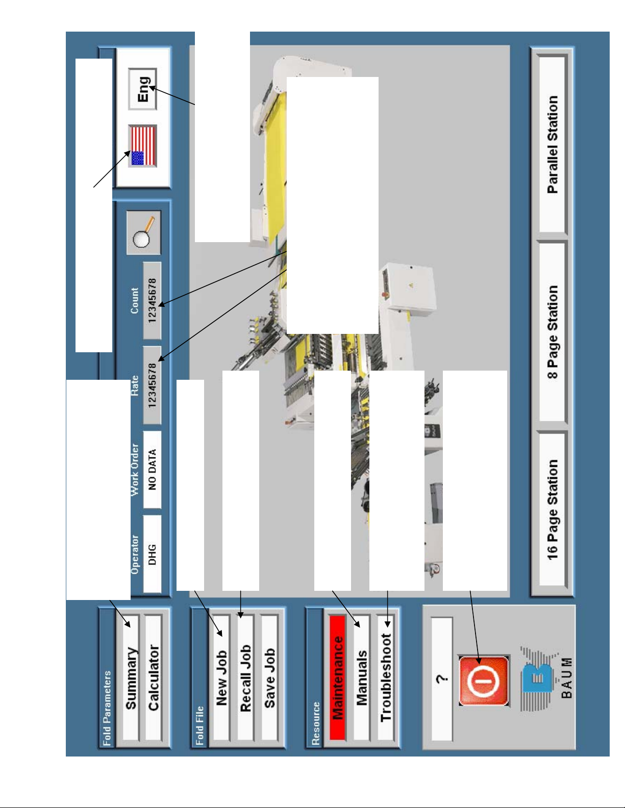
Touch this button to change from
Page 18 of 45
TP10497
standard, decimal, standard fractional
or metric.
This shows the count and rate from the
machine display. This is reset from the
machine control panel (see the operators
manual for instructions). Touch the numbers
in the count box to make the count display
larger and touch it again to change it back.
Touch this button to change the language. English,
Spanish, German or French.
Touch this button to go to the
summary screen for the current job.
The summary screen shows all of your
settings and any notes you want to add
Touch this button to setup a new job
Touch this button to recall a previously
saved job
Touch this button to see parts and
operators manuals for your machine.
Touch this button for troubleshooting
help with any problems you may be
having
Touch this button before turning off
the machine. Once the screen says it is
safe to turn off your computer then
you can turn off the machine
Page 21

nd
Page 19 of 45
TP10497
Touch this button to bring up
a job calculator that will help
you determine how long a job
will take.
When this box is red it indicates
you have made a change to the
setup. This change will be lost if the
system is powered down. If you
would like to save this change touch
this button
When this box is red it indicates
there is a maintenance item that
needs your attention. You can
touch this button anytime to see
recommended maintenance items
and how to do them.
station) the buttons will not be displayed.
rd
station) or a 16 page(3
section. You can also make changes to these settings if necessary. If you do not have an 8 page(2
Touch these buttons to see the current settings for the fold plates and Baumsets for the indicated fold
Page 22

Page 20 of 45
TP10497
This box contains the current work order.
Touch the box to enter a new work order.
When you touch the box a keyboard will pop
up, Just enter the work order and touch enter.
This box contains the initials of the operator
currently logged on. ??? indicates no
operator is currently logged on. Touch the
box to log on. A keyboard will pop up.
If this is the first time you have logged on touch the
NEW button then type your name and touch enter. It
will ask for a password, if you do not enter a password
at this time you will never be ask for one in the future.
If you type a password and touch enter you will need
to enter this password every time you log in. If you
have logged in before just type in your initials and
touch enter then type in a password and touch enter if
necessary.
Page 23
Page 21 of 45
TP10497
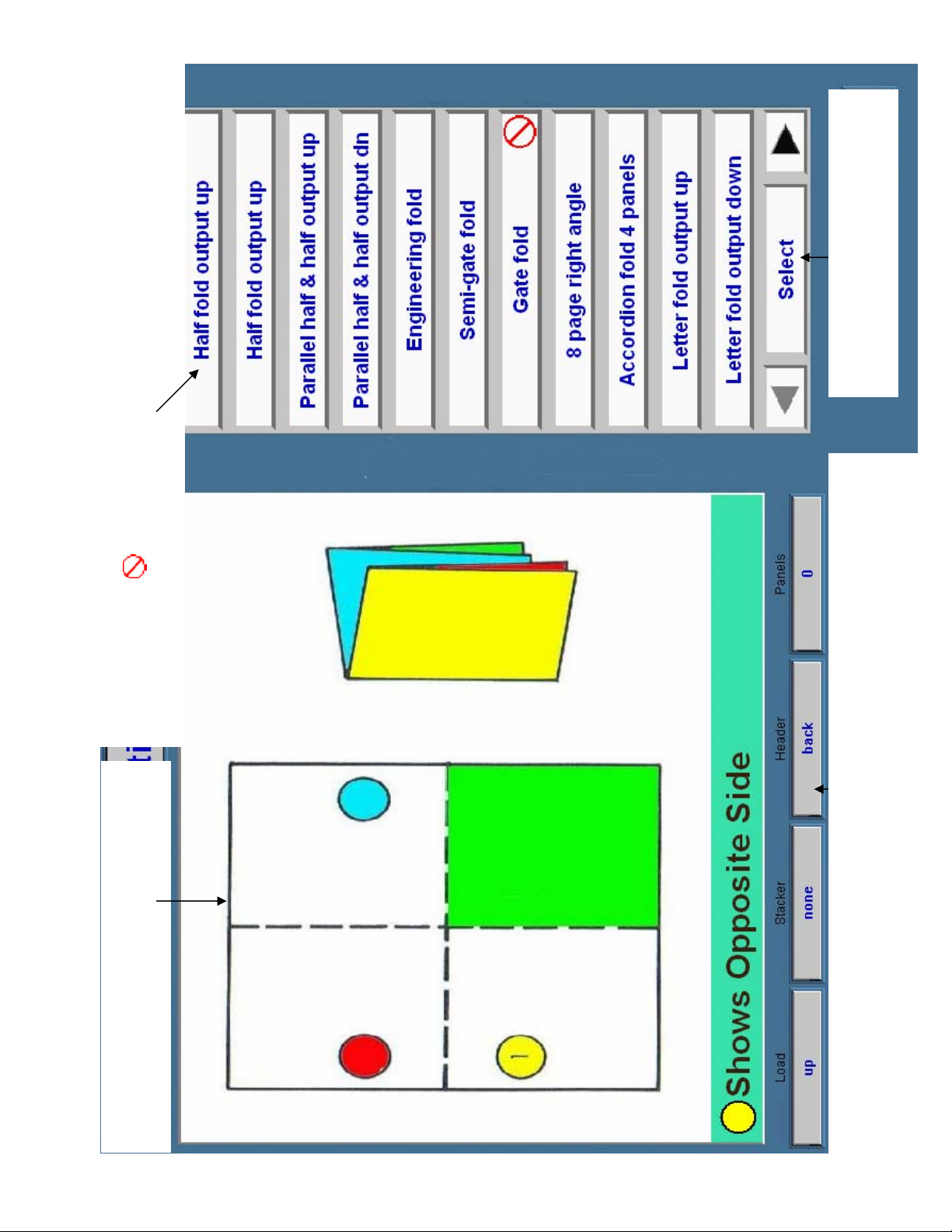
in the box to the left.
Press here to select the fold displayed
This box show the available folds. Touch a button to see the fold in the box on the left.
Touch the ► Arrow at the bottom of the page to see the next pages. Press the ◄ to come
back to this page. A on the button indicates the fold is not possible with you current
configuration.
circle indicates the opposite side
This box shows the selected fold. A color in a
determine for the selected fold.
and the label will come out face up on the stacker. Panels indicates the number of panels in a
Paper orientation shows how to load the paper and how the address or label will come out on
the stacker. Example: Load the address or label down and forward (toward the sucker wheel)
roll or accordion fold. If the stacker display shows none, the output on the stacker is difficult to
Page 24
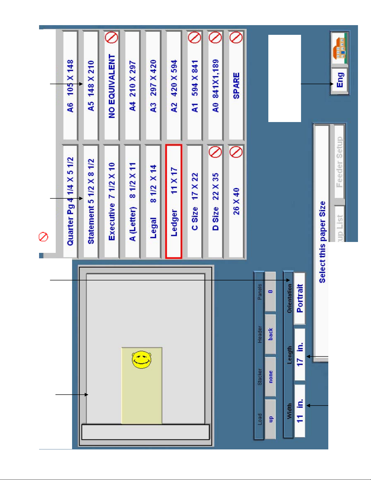
Touch one of these boxes to select a paper size.
Page 22 of 45
TP10497
A on the button indicates that paper size will not run on your machine
from inch to metric
Touch this box to change
button.
down and forward). You can change this from portrait
(shown) to Landscape and back by touching the orientation
This box shows how the paper is loaded (label or address face
size. Do this for both the width and length.
a keypad will pop up. Using the keypad enter the paper custom paper
Touch these boxes to enter a custom paper size. When you touch a box
Page 25

the main screen.
Page 23 of 45
TP10497
Touch this button to go to
feeder setup screen.
Touch this button to go to the
activate the see setup list and to feeder setup buttons.
and orientation to fold/paper setup completed. This will also
been selected. The text will change from select this paper size
Touch this box once the desired paper size and orientation have
setup list is explained on the next page.
Touch this button to see the setup list. The
the summary screen.
Touch this button to go to
Touch this button to go back
to the fold select screen.
Page 26
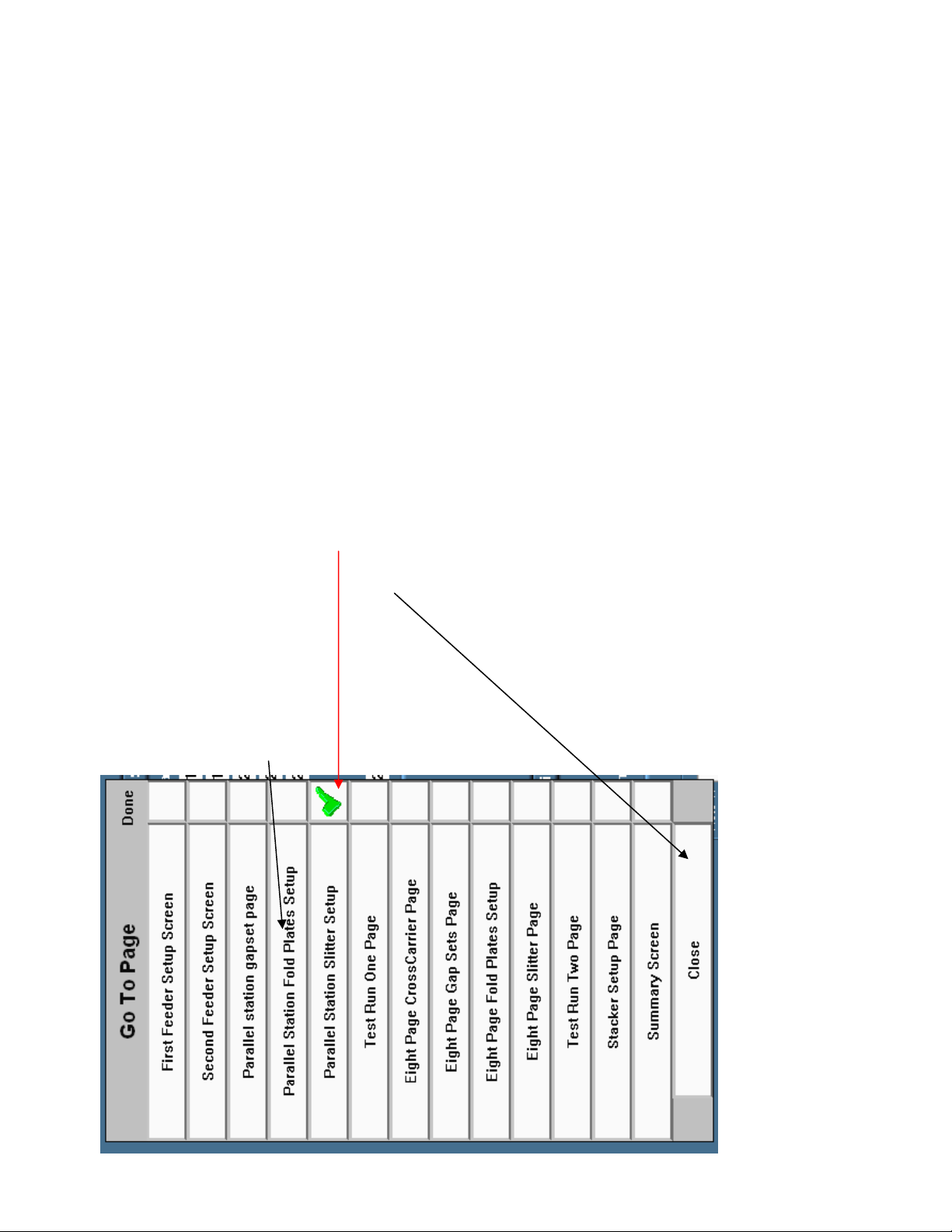
This will come up on the left of any setup screen when the see setup list
Page 24 of 45
TP10497
button is touched. This list shows all of the setup screens needed for the
selected fold. You can go to any screen on the list just by touching the
corresponding button. The done button shows a green checkmark when the
page is completed and the press when setup complete button has been
touched. This can help you keep track of where you are in the setup of the
job. You can also set the done button to a green checkmark by touching it
when this list is up. To close the setup task list without going to a different
page just touch the close button.
Page 27

save job screen.
Page 25 of 45
TP10497
the setup list. The setup
Touch this button to see
list is explained on page 4.
needs 1 sheet of paper and fold plate number 1 is set to 8 ½ inches to do the selected fold. Touch
blue or gray boxes indicate the fold plate setting. Example: On the parallel station gapset number 1
station required to do the selected fold. The black boxes indicate the gapset and fold plate numbers,
These areas show the number of sheets that go under each gapset and the fold plate settings for every
the dark blue boxes indicate the number of sheets that go under the corresponding gapset and the light
you can make any changes needed to the number of sheets in the gapsets or the fold plate settings.
anywhere in each area and it will take you to the corresponding adjustment screen, from that screen
This area shows the feeder settings.
Where to set the non-operator side paper
guide and the blow tube settings.
This area shows the suggested scoring
dies for each station to run the selected
fold.
blue box under the fold saved name to go to the
is saved what name it is saved under. Touch the
This area shows the current fold selected and if it
Page 28

Page 26 of 45
TP10497
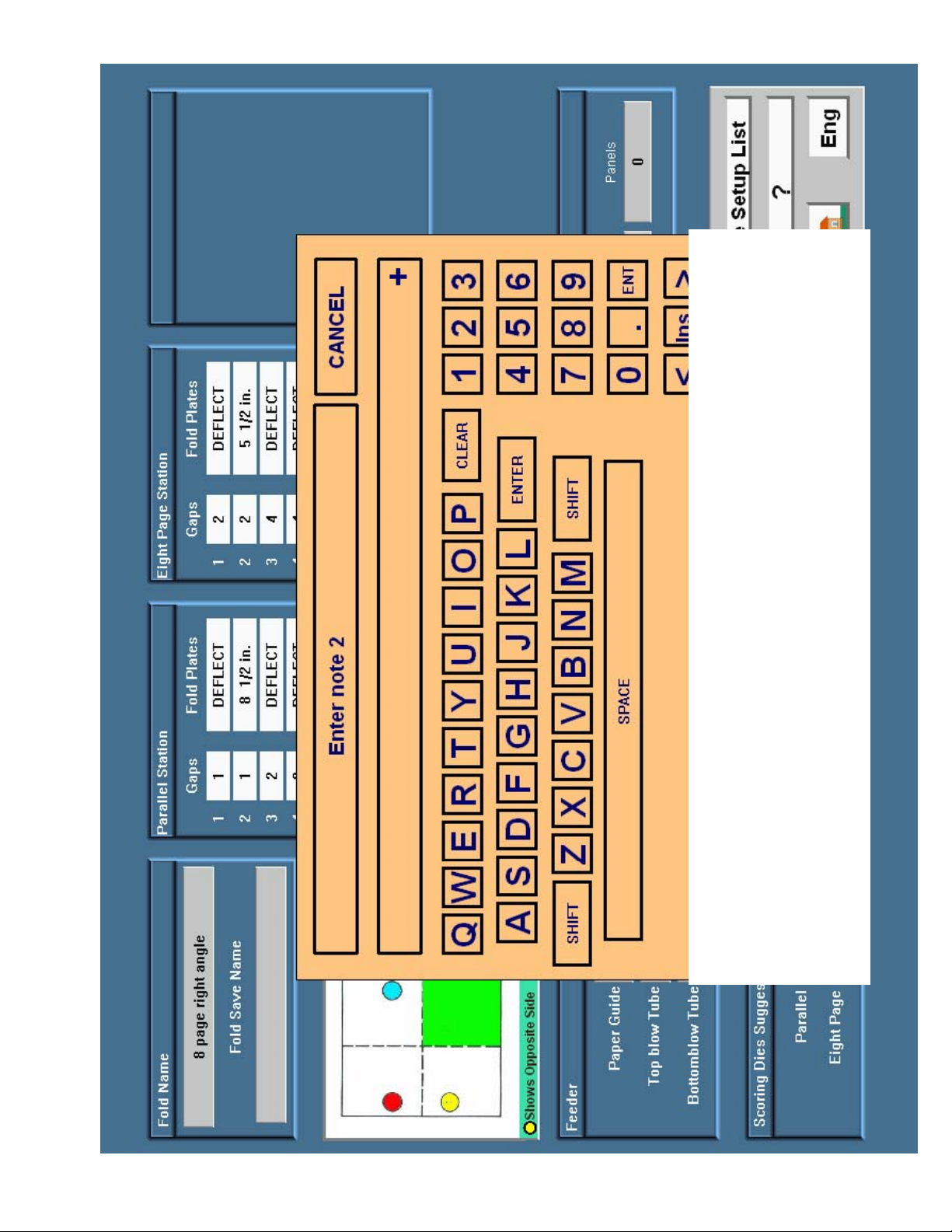
In this area you can enter up to 4 notes with up to 55 characters per note to be saved with a fold job. These
could contain information like what speed it ran best at if it needed a slit or a perf and what type of perf. To
enter a note just touch one of the gray lines next to a note: and a keypad will pop up (see the next page).
Page 29
r
Page 27 of 45
TP10497
button or the Ent button.
Use the keypad to enter a note, the clear button will clear everything in the display, this is
recommended if you are entering a new note. The Ins/Del button is used to control what happens
when you touch the arrow buttons. If the button displays Ins you are in insert mode the < and >
buttons will move the curser left or right then anything you type will be inserted where ever the
curser is located. If you Touch the button it will change to Del now you are in delete mode, if you
touch the < button it will delete the character to the left of the curser and if you touch the >
button it will delete the character to the right of the curser. After you are finished typing your note
touch the Ente
Page 30
Page 28 of 45
TP10497
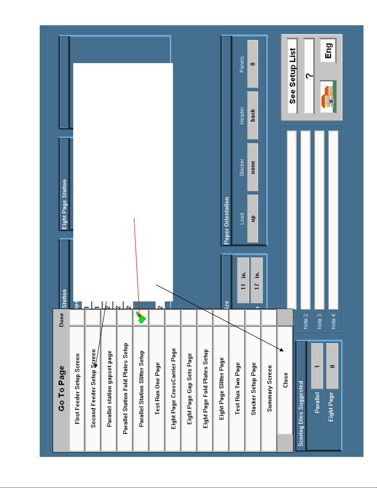
This will come up on the left of any setup screen when the see setup list
button is touched. This list shows all of the setup screens needed for the
selected fold. You can go to any screen on the list just by touching the
corresponding button. The done button shows a green checkmark when the
page is completed and the press when setup complete button has been
touched. This can help you keep track of where you are in the setup of the
job. You can also set the done button to a green checkmark by touching it
when this list is up. To close the setup task list without going to a different
page just touch the yellow close this window button.
Page 31
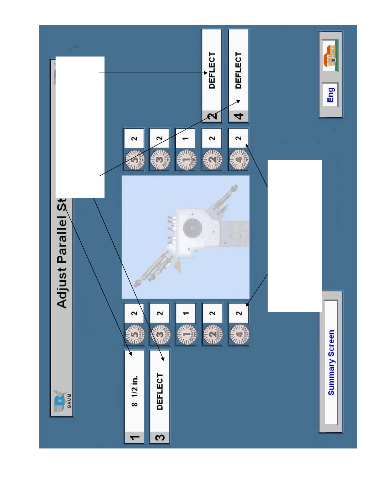
4 boxes show the settings for the fold plates.
Page 29 of 45
TP10497
To make a change to one of the settings just
touch the box you wish to change and a
keypad will pop up. This is shown and
explained on page 2.
These rows of boxes shows the number of sheets
to be placed under the gapsets. In this example
gapset 4 gets 2 sheets. To make a change to one
of the settings just touch the box you wish to
change and a keypad will pop up. This is shown
and explained on page 3.
Page 32

This line indicates the fold plate you are
Page 30 of 45
TP10497
making a change to
This is the current setting (0 or blank =
deflect). If a number is displayed touch the C
to clear it then enter the desired number. The
BK SP button will clear the last number
entered. Touch done when you have finished.
Page 33

This line indicates the gapset you are making
Page 31 of 45
TP10497
a change to.
This is the current setting touch the C to clear
it then enter the desired number. Touch done
when you have finished.
Page 34

These boxes tell you how many
Page 32 of 45
TP10497
days are left until the maintenance
item needs done. The grease
canister is fixed all the others can
be set as desired.
After the maintenance is
preformed touch the box to reset
the timer.
Press this to return to the main
screen
Use the numbers to enter the time interval
for the selected maintenance item then
press done. Enter zero to turn off the
selected timer.
Touch one of these boxes to set the timer for the maintenance item to the
right of that box. When you touch the box a keypad will pop up.
Click on any of these boxes to see how to
perform a maintenance item
Page 35

Page 33 of 45
TP10497
or metric.
decimal inch, fractional inch
Touch this box to change the
sheet separation display from
sheet gap.
Touch this box to enter the
per minute.
or metric.
sheet length display from
decimal inch, fractional inch
Touch this box to change the
Touch this box to enter the
current selected sheet length.
sheet length. The default is the
other down time.
Not including setup or any
will take to run the entire job.
This box displays how long it
Touch here to change the
folder speed display from
meters per minute to inches
out how to read the current folder speed.
speed. Touch the SEE HOW button to find
Touch this box to enter the folder speed you
plan to run the job. The default is 60% of full
per hour.
This box displays the sheets
total job size.
Touch this box to enter the
per minute.
This box displays the sheets
Page 36

1 1
Page 34 of 45
TP10497
REV:
SHEET OF
ASSEMBL Y NUMBER:
IFOLD DISPLAY MOUNTING LOCATION
IFOLD DISPLAY
DESCRIPTION:
UNIT NAME:
BAUMFOLDER
CORPORATION
Page 37

1 2
Page 35 of 45
TP10497
REV:
SHEET OF
FK2001484
ASSEMBL Y NUMBER:
IFOLD DISPLAY ADAPTOR KIT
IFOLD DISPLAY
DESCRIPTION:
UNIT NAME:
BAUMFOLDER
CORPORATION
Page 38

2 2
Page 36 of 45
TP10497
REV:
SHEET OF
FK2001484
ASSEMBL Y NUMBER:
IFOLD DISPLAY ADAPTOR KIT
IFOLD DISPLAY
DESCRIPTION:
UNIT NAME:
BAUMFOLDER
CORPORATION
Page 39

1 2
Page 37 of 45
TP10497
REV:
SHEET OF
FK2001485
ASSEMBL Y NUMBER:
IFOLD DISPLAY MOUNT
IFOLD DISPLAY
DESCRIPTION:
UNIT NAME:
BAUMFOLDER
CORPORATION
Page 40

2 2
Page 38 of 45
TP10497
REV:
SHEET OF
FK2001485
ASSEMBL Y NUMBER:
IFOLD DISPLAY MOUNT
IFOLD DISPLAY
DESCRIPTION:
UNIT NAME:
BAUMFOLDER
CORPORATION
Page 41

1 2
Page 39 of 45
TP10497
REV:
SHEET OF
FK2001370
ASSEMBL Y NUMBER:
DISPLAY-ENCLOSURE
IFOLD DISPLAY
DESCRIPTION:
UNIT NAME:
BAUMFOLDER
CORPORATION
Page 42

2 2
Page 40 of 45
TP10497
REV:
SHEET OF
FK2001370
ASSEMBL Y NUMBER:
DISPLAY-ENCLOSURE
IFOLD DISPLAY
DESCRIPTION:
UNIT NAME:
BAUMFOLDER
CORPORATION
Page 43

1 2
Page 41 of 45
TP10497
REV:
SHEET OF
FK2001426
ASSEMBL Y NUMBER:
IFOLD DISPLAY MOUNT
IFOLD DISPLAY
DESCRIPTION:
UNIT NAME:
BAUMFOLDER
CORPORATION
Page 44

2 2
Page 42 of 45
TP10497
REV:
SHEET OF
FK2001426
ASSEMBL Y NUMBER:
IFOLD DISPLAY MOUNT
IFOLD DISPLAY
DESCRIPTION:
UNIT NAME:
BAUMFOLDER
CORPORATION
Page 45

1 1
Page 43 of 45
TP10497
REV:
SHEET OF
FK2001500
ASSEMBL Y NUMBER:
CABLE ASSY. POWER
IFOLD DISPLAY
DESCRIPTION:
UNIT NAME:
BAUMFOLDER
CORPORATION
Page 46

1 1
Page 44 of 45
TP10497
REV:
SHEET OF
FK2001501
ASSEMBL Y NUMBER:
CABLE ASSY. COMMUNICATIONS
IFOLD DISPLAY
DESCRIPTION:
UNIT NAME:
BAUMFOLDER
CORPORATION
Page 47

1 1
Page 45 of 45
TP10497
REV:
SHEET OF
FK7600179
ASSEMBL Y NUMBER:
SCHEMATIC-IFOLD
IFOLD DISPLAY
DESCRIPTION:
UNIT NAME:
BAUMFOLDER
CORPORATION
 Loading...