

Page 1
BA U
M
BAUM 2020
1ST STATION FOLDER W/PILE FEED
INSTRUCTION MANUAL
©Baumfolder Corp., 2006 Printed in U.S.A. TP10243-5
PAGE 1 TP10243-5
Page 2

© 2006 BAUMFOLDER CORPORATION
All Rights Reserved
WARNING
• Do not operate this machine without all guarding in place.
• Do not make adjustments or perform maintenance on this machine with power on.
• Keep the machine and the work area clean and free of spills to prevent accidents.
• Be sure to replace any safety decals that may have been detached for any reason.
Baumfolder Corporation reserves the right to make changes in design or to make additions or
improvements in its products without imposing any obligation upon itself to install them on its
previously manufactured products. It is recommended that modifications to this equipment not be
made without the advice and express written consent of Baumfolder Corporation.
FOLDER IDENTIFICATION
MODEL NO: _______________________________ SERIAL NO: _____________________________
SALES AGENCY:____________________________________________________________________
INSTALLED BY: _____________________________________________ DATE: ________________
PHONE NO: _______________________________
TP10243-5 PAGE 2
Page 3

CONTENTS
DESCRIPTION PAGE
I.) Safety .................................................................................................................................................................. 6
II.) Introduction Overview ........................................................................................................................................ 7
III.) Transportation/Installation ................................................................................................................................7
IV.) Squaring the Machine ........................................................................................................................................ 7
V. ) Electrical Connections ....................................................................................................................................... 8
1.0 .Wiring the Pump (3 phase) ................................................................................................................... 8
1.1. Wiring the Pump (1 phase).................................................................................................................................8
1.2. Other Connections ............................................................................................................................... 8
1.3 .Tapping the Transformer ...................................................................................................................... 9
1.4 .Pump Connections ................................................................................................................................9
VI.) "QUICK START" INSTRUCTION'S .............................................................................................................. 10
V II .) Installing Fold Plates & Stacker Delivery ...................................................................................................... 21
VIII.) Operator Controls ............................................................................................................................................ 21
1.0 .Setting Folding Speed ......................................................................................................................... 21
1. 1 .Setting Stacker Belt Speed...................................................................................................................21
1.2 .Emergency Stop Button.......................................................................................................................21
1.0 Control Panel BAN-5................................................................................................................................ 22
1.1 .Displays...............................................................................................................................................22
1.2 . Machine Status Indicators .................................................................................................................. 22
1.3 . Machine Control Pushbuttons ............................................................................................................22
1.4 .Keypad Buttons with Selection Indicators .......................................................................................... 23
1.5 .Keypad Buttons for Selection Adjustments ........................................................................................ 23
2.0 RUN MODE FUNCTIONS ................................................................................................................................23
2.1 .Machine Setup and Diagnostic Mode................................................................................................. 23
2.2 .Counter Setup Mode ........................................................................................................................... 27
2.3 .Easy Mode and Continuous Cycle Mode ........................................................................................... 28
2.4 .Learn Mode ......................................................................................................................................... 28
2.5 .Make Ready Mode .............................................................................................................................. 29
2.6 .Network Job Mode .............................................................................................................................. 30
2.7 . Production Mode ................................................................................................................................ 30
3.0 LOGIC BOARD STATUS INDICATORS ............................................................................................................. 31
4.0 Process Variables Definitions.................................................................................................................. 32
4.1 .Total Input Count ................................................................................................................................ 32
4.2 .Total Output Count ............................................................................................................................. 32
4.3 .Batch Down Count .............................................................................................................................. 32
4. 4 .Number of Batches .............................................................................................................................. 32
4. 5 .Current Rate......................................................................................................................................... 32
4. 6 .Main Drive Run Time .......................................................................................................................... 32
4.7 .Main Drive Velocity.............................................................................................................................32
4. 8 .Waste Count (DCT500) ....................................................................................................................... 32
5.0 COUNTER SETUP VARIABLES ....................................................................................................................... 32
5.1 .Batch Preset.........................................................................................................................................32
5.2 .Batch Output Type .............................................................................................................................. 32
5. 3 .Batch Output Time .............................................................................................................................. 33
5.4 .Sheet Length ....................................................................................................................................... 33
5. 5 .Gap Length .......................................................................................................................................... 33
5.6 .Suction Length .................................................................................................................................... 33
6.0 SYSTEM MESSAGES AND RUN MESSAGES ....................................................................................................... 34
6.1 .Power-Up Fault Messages .................................................................................................................. 34
6.2 .Run Time Fault Messages ................................................................................................................... 35
6.3 .Machine Run Error Messages ............................................................................................................. 36
PAGE 3 TP10243-5
Page 4

CONTENTS
DESCRIPTION PAGE
IX.) Pile Feeder Operation ...................................................................................................................................... 37
1.0 .Loading ............................................................................................................................................... 37
1.1 .Hold-down Locations .......................................................................................................................... 37
1. 2 .Air and Vacuum Setting.......................................................................................................................37
1.3 .Front Blow Tube Settings....................................................................................................................38
1.4 .Vacuum Wheel .................................................................................................................................... 38
X.) Register Operation .......................................................................................................................................... 39
1.0 .Double Sheet Detector ........................................................................................................................ 39
XI. ) Baumset Adjustment ........................................................................................................................................ 40
1.0 .Adjusting Folding Rollers ................................................................................................................... 40
XII.) Setting Fold Plates ........................................................................................................................................... 41
XIII.) Setting Deflectors ............................................................................................................................................ 41
XIV.) Stacker Operation ........................................................................................................................................... 42
XV.) Scoring/Slitting/Perforating........................................................................................................................... 43
1. 0 .Slitter Shaft Removal ........................................................................................................................... 43
1.1 .Scoring ................................................................................................................................................ 44
1.2 .Perforating ...........................................................................................................................................45
1.3 .Slitting ................................................................................................................................................. 46
1.4 . Trimming .............................................................................................................................................. 47
1. 5 .Trimming a Strip from Center of Sheet ................................................................................................. 48
1. 6 .Blade Installation................................................................................................................................. 48
XVI.) Lubrication/Maintenance ................................................................................................................................. 50
XVII.) Technical Specifications .................................................................................................................................. 51
XVIII.) Accessories ...................................................................................................................................................... 51
XIX.) Troubleshooting ............................................................................................................................................... 52
XX.) Operating Tips ................................................................................................................................................. 54
XXI.) Principles of Mechanical Folding .................................................................................................................... 56
XXII.) Job setup example ............................................................................................................................................. 57
XXIIi.) Folding Chart ................................................................................................................................................... 61
XXIV .) Manual Usage ................................................................................................................................................... 63
XX V.) T ypical Layout & Sheet Orientation ................................................................................................................ 64
XXVI.) Impositions ....................................................................................................................................................... 65
#1 4 - PAGE ............................................................................................................................................... 65
#2 4 - PAGE, DOUBLE IMPOSITION........................................................................................................65
#3 6 - PAGE, ST ANDARD......................................................................................................................... 65
#4 6 - P AGE, ACCORDION ....................................................................................................................... 65
#5 8 - PAGE, P ARALLEL IMPOSITION .................................................................................................... 65
#6 8 - P AGE, RIGHT ANGLE ..................................................................................................................... 65
#7 8 - PAGE, RIGHT ANGLE OBLONG ..................................................................................................... 66
#8 8 - P AGE, RIGHT ANGLE DOUBLE IMPOSITION............................................................................... 66
#9 8 - P AGE, PARALLEL OVER & OVER .................................................................................................. 66
#10 12 - P AGE BOOK, SADDLE STITCH ................................................................................................... 66
#11 12 - P AGE BOOK, SADDLE STITCH ................................................................................................... 66
#12 12 - P AGE LETTER FOLD, HEADS OUT ............................................................................................. 66
#13 12 - P AGE LETTER FOLD, HEADS IN ................................................................................................. 67
#14 12 - PAGE LETTER FOLD, ACCORDION.............................................................................................67
#15 16 - PAGE, THREE RIGHT ANGLE BOOK IMPOSITION.................................................................... 67
#16 12 - P AGE FOLDER, HEADS OUT ....................................................................................................... 67
#17 24 - PAGE BOOKLET ........................................................................................................................... 67
#18 32 - PAGE BOOK..................................................................................................................................67
XXVII.) Service ............................................................................................................................................................ 68
TP10243-5 PAGE 4
Page 5

List of Tables
DESCRIPTION PAGE
Table 1. Machine Setup Parameter List "A" ........................................................................................................................ 24
Table 2. Machine Monitor Parameter List ............................................................................................................................ 24
Table 3. Machine Setup Parameter List "B" ......................................................................................................................... 25
Table 4. Machine Diagnostic Parameter List......................................................................................................................... 26
Table 5. Future Features List ................................................................................................................................................ 26
Table 6. Machine Usage Status Parameter List ..................................................................................................................... 27
Table 7. Output Type Animations ........................................................................................................................................ 27
Table 8. Count Source Selection ........................................................................................................................................... 28
Table 9. Learn Mode Status ................................................................................................................................................. 28
Table 10. Suction Mode Symbols ........................................................................................................................................ 29
Table 11. Suction Length Function ....................................................................................................................................... 29
Table 12. Determining the Large Display Contents............................................................................................................... 30
Table 13. Reset mode Selection............................................................................................................................................. 31
Table 14. LED Status Indicators............................................................................................................................................ 31
Table 15. Output Delay and Duration ................................................................................................................................... 33
Table 16. Power Up Fault Messages..................................................................................................................................... 34
Table 17. Run Time Fault Messages ..................................................................................................................................... 35
Table 18. Machine Run Error Messages ............................................................................................................................... 36
PAGE 5 TP10243-5
Page 6

SAFETY FIRST
10. Make sure that all safety devices are in place before
restarting the machine.
Your new Baum paper folding machine has been designed
in accordance with the latest safety specifications. The
warning and caution labels on the machine must remain in
place. Make sure all guarding provided is in place before
starting up and running the machine.
Due to the nature of the work process of paper folding
machines, there are parts and areas on the machine which
cannot be completely covered without interfering with the
operation of the machine. Therefore, sound personal work
habits and strict observance of all safety precautions is
required for the protection of the operator, co-workers, and
the machine.
Be sure to follow these
safety precautions:
1. Study the safety instructions at your plant and those
provided in this manual.
2. Study the operating instructions carefully before
operating the machine.
3. Make sure that your co-workers are familiar with the
work process, potential danger areas,
and all necessary safety measures.
11. Never clean moving parts of the machine (rollers,
shafts, etc.) or remove any test sheets or paper jams
while the machine is running.
12. Keep the floor around the entire machine clean.
Immediately clean up any oil, grease, or paint spills
from the floor. Remove tools, cleaning cloths, and
paper scraps from all work areas.
13. Never allow unauthorized personnel to make adjustments on the machine, remove problem sheets, or start
the machine.
14. Never climb over the machine or crawl into it while it is
turned on.
15. Immediately repair or replace any safety devices which
have become ineffective or are missing.
16. Report any exposed cables or exposed electrical
connections.
17. Always have a certified qualified electrician perform all
electrical maintenance.
18. Do not make adjustments or perform maintenance with
the power on.
4. Make sure that the machine is in good working order
before turning it on.
5. If the machine suddenly stops for whatever reason, do
not restart it right away. Someone may have stopped
the machine, but failed to press the emergency (Stop)
button. If the machine is restarted unexpectedly, your
co-worker could be seriously injured.
6. Always press the emergency (Stop) button first if you
stop the machine for adjustments or maintenance work
which must not be done while the machine is in
operation.
7. For extensive maintenance or repair work, turn off the
main power supply.
8. Never use improper or defective tools.
9. After making adjustments or after doing maintenance
or repair work, always make sure that all tools and
other objects are removed from the machine. Otherwise, they might fall into the machine, causing severe
damage or injuries.
19. Become familiar with and follow the safety labels on
the next page. Replace any of these labels that are
damaged or lost.
Additional Notes:
20. Do not attempt to remove a paper jam, no matter how
minor it may appear to be, while the machine is
running.
21. When cleaning the fold rolls, use the handwheel for
turning. Be sure the power to the machine is off.
22. Turn off the machine before making any adjustments to
the scoring, perforating, or slitting attachments. Keep
hands and clothing away from the slitter shafts when
the machine is running.
TP10243-5 PAGE 6
Page 7
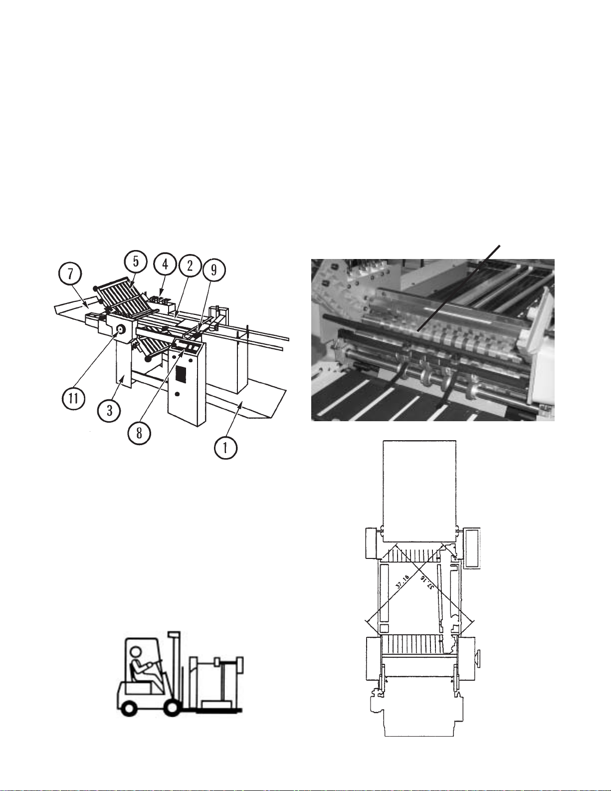
INTRODUCTION OVERVIEW
The 1st station [parallel] folder with pile feeder
contains the following main components (Figure 1):
1. Pile Feeder
2. Register
3. 1st Station Folder (Parallel)
4. Fold Roller Gapsets
5. Fold Plates
6. Slitter Shafts (not shown)
7. Delivery (Stacker)
8. Operator Controls
9. Double Sheet Detector (Caliper)
10. Vacuum Pump (not shown)
11. Handwheel
Level the machine on the floor. Place a spirit level on
the #2 fold roller (Figure 3) and on the feeder crossmembers.
SQUARING THE MACHINE
It is essential that this folding machine is square in
order for it to work properly. To square the machine,
measure diagonally across corners from feeder frame to
folder frame (Figure 4). Dimensions shown are approximate. Be sure that the measurements taken are identical
within 1/16-inch. If the machine is out of square, shift the
frames in the direction needed until the proper squareness is
obtained.
#2 FOLD ROLL#2 FOLD ROLL
#2 FOLD ROLL
#2 FOLD ROLL#2 FOLD ROLL
Figure 1Figure 1
Figure 1
Figure 1Figure 1
TRANSPORTATION/INSTALLATION
As soon as you receive your new folder, and before
removing the machine from the skid, check carefully for any
damage to the shipments. If any damage is found, promptly
contact your Baumfolder sales representative.
To lift the folder from the skid, place the fork lift rails
under the lower rails as shown in Figure 2. Note that the
fork lift must have at least a 1500 lb. capacity.
Remove all rust protection coating after unpacking the
folder.
Figure 2Figure 2
Figure 2
Figure 2Figure 2
Figure 3Figure 3
Figure 3
Figure 3Figure 3
Figure 4Figure 4
Figure 4
Figure 4Figure 4
PAGE 7 TP10243-5
Page 8
#4
#5
U1
#1
W2
V1
#2
U2
W1
#3
V2
GND
G/Y
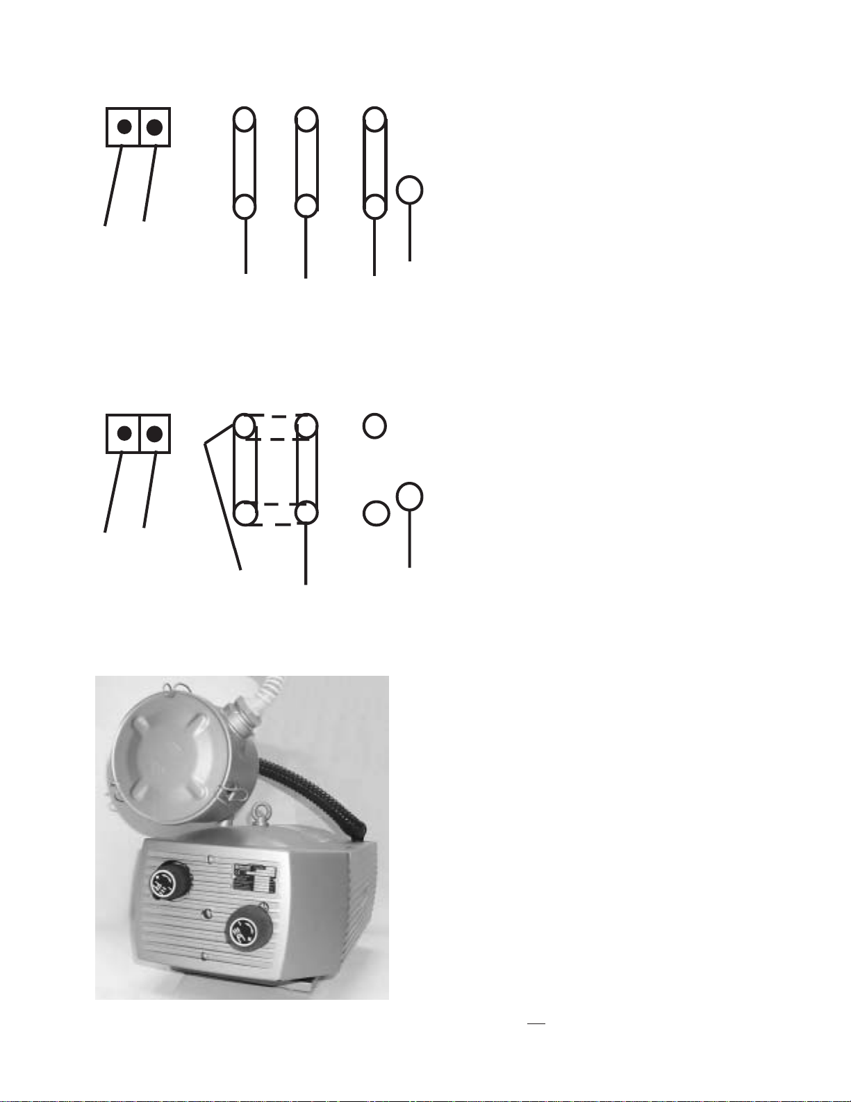
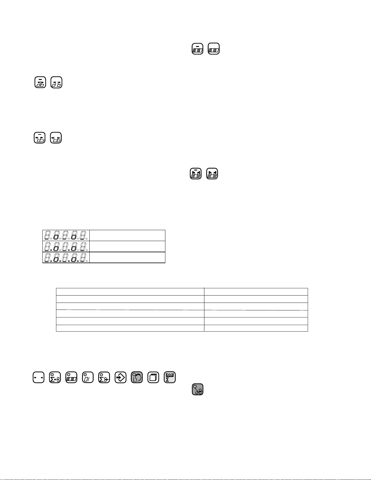
ELECTRICAL CONNECTIONS
1.0 Wiring the Pump (2020 / 3 phase)
Connect the pressure/vacuum pump at the pump
junction box (Figure 5) using the attached cable. Follow
the instructions to the left for the proper connections.
Turn the main power switch to the "ON" position.
Switch the pump on momentarily and check for proper
pump rotation as indicated by the rotation arrow on the
pump. Immediately turn off the pump if the rotation is
wrong.
If the rotation is incorrect interchange any two of the
three wires #1, #2, or #3 in the pump motor terminal box.
W2
#4
#3
U1
#1
Note: Dotted line indicates the cnange
you need to make if the pump
is running backwards
1 PHASE ONLY
V1
#2
U2
W1
V2
GND
1.1 Wiring the Pump (2020 / 1 phase)
Connect the pressure/vacuum pump at the pump
junction box (Figure 5) using the attached cable. Follow
the instructions to the left for the proper connections.
G/Y
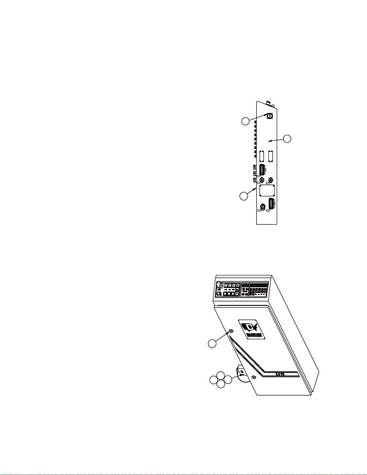
1.2 Other Connections
Refer to the serial number plate for electrical
requirements. The serial number plate notes the voltage,
phase and hertz, minimum time delay fuse, total machine
amperage, and minimum wire conductor size for the main
power connection.
The main power is connected directly to the line side of
the main power switch. In a (2020 / 1 phase) use L1 and L2
only. In a (2020 / 3 phase) use L1, L2, L3.
All electrical connections are to be made by a certified
electrician. Refer to local building electrical codes for proper
and safe connections.
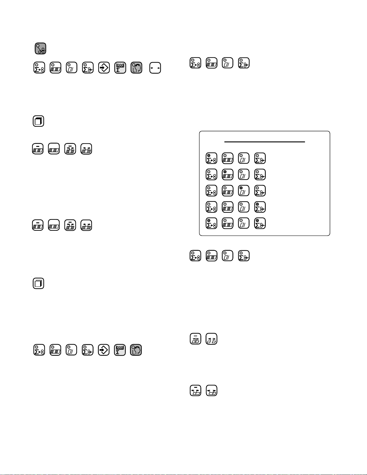
For the following items, refer to Figure 6. Run a power
cable from your distribution box to the main control box on
the pile feeder. Turn the main power switch to zero. Using
the appropriate tool, open the latches on the control box
door and open the door.
Figure 5
TP10243-5 PAGE 8
NOTE: The door is connected to the main box by a ground
wire that should not be removed.
Page 9
1.3 Tapping the Transformer
Pass the power cable through the strain relief and the
hole provided in the control box. Connect the power cable to
the open terminals on the main disconnect in the control box.
The incoming ground wire should be attached to the ground
stud located in the lower right-hand corner of the control box.
To tap the transformer, read the incoming voltage at the
main disconnect. Then move the wire numbered 7L2 on the
transformer to the corresponding tap on the transformer.
Tighten all screw connections and close the door before
switching the machine on.
A connector is provided for power connection to the
stacker. The stacker must be plugged into the socket for the
machine to operate, if not, install the blind plug attached to
the box.
A connector is provided for power connection to the
second station (8-page) fold unit. If no additional folding
station is to be connected, the connector must be closed off
with a blind plug.
1.4 Pump Connections
Connect the air hoses to the pump. The small diameter
hose is connected to the vacuum side of the pump. Connect
it to the barbed fitting above the ball valve on one end and
the other end to the vacuum solenoid valve on the pile
feeder.
Connect the larger diameter hose to the remaining
outlet port on the pump and to the barbed fitting on the pile
feeder at the end of the blow bar.
Troubleshooting tips and actions required for the
display messages that may appear on the control readout
may be found the "Diagnostic Messages" section of the
manual.
3
2
1X7
1X10
1X12
1
1X1
1X2
4
6
5
8
7
Figure 6
PAGE 9 TP10243-5
Page 10

BAUMFOLDER 2000 Series “QUICK START” INSTRUCTIONS
TURNING THE MAIN SWITCH ON
When you turn on the Main Power Switch located on the side of the Control Box , you must let
the Control automatically run a self-test. During the self-test
a button will cause an Error Message to appear in the Main Display. To CLEAR Message turn Power
OFF at the Main Power Switch—WAIT
5 SECONDS, then turn Power back on.
1. Turn on Main Power Switch on left side of control enclosure.
- Wait until control finishes self-test.
2. Load paper on Pile Feed Table. Press Pile up GREEN Button
Pile will raise automatically to correct height.
NOTE: To STOP Pile—Press RED Button
3. To START Drive Motor & Pump—Press GREEN Button ABOVE the symbol.
DO NOT Press any buttons. Pressing of
To STOP Drive Motor —Press RED Button BELOW the symbol or Press EMER-
GENCY STOP BUTTON
RAISING AND LOWERING THE PILE FEEDER LIFT TABLE
1. After loading paper onto Pile Feeder Lift Table, Press the GREEN Button
This will raise the paper to the proper feeding height automatically. You
can stop the Pile Feeder Lift Table by Pressing the RED Pile Feeder
STOP Button
2.
To lower the Pile Feeder Table, you must first Press the RED Pile Feeder
STOP Button
TP10243-5 PAGE 10
Page 11

Then Press the GREEN Button to lower Pile Feed Table. The Table will lower and stop
automatically in its lowest position.
STARTING PRODUCTION WITH THE BAUM 2020
1. To START the Folder Drive, Press the GREEN Button on the Control Panel
just ABOVE the symbol, this will Start the Folder Drive and the Pump will automatically
come on.
2. To STOP the Folder Drive, Press the RED Button on the Control Panel just BELOW the
symbol or Press the RED EMERGENCY STOP Button on the Control Panel or on the
Stacker Control Panel. The Folder Drive will STOP, The Pump may continue to run for about 7
seconds. If you want to stop the pump at the same time as the folder drive press the Drive
STOP button twice within a 0.5 seconds.
The Pump circuit has a minimum ON time of 4 SECONDS. If the Pump is commanded OFF
within 4 seconds after it is started, it will continue run for the duration of the 4 seconds and then
shut OFF.
3. To Turn the Pump ON without the Folder Drive coming On, Press the GREEN Button ABOVE
the symbol
4. To Turn the Pump OFF, Press the RED Button BELOW the symbol NOTE: the Pump
will stay ON for at least 4 SECONDS before being able to shut off.
Easy Mode:
This mode is an automatic setup mode that sets the sheet gap to 1 inch and vacuum duration to 5
inches. Most jobs may be ran with this mode of operation. A Z-fold or a product with a window
will require the Continuous Mode of operation. You can not change the sheet gap or vacuum
duration settings manually using the Easy-Mode. Only the DCT500 mode or Continuous Cycle
mode allows adjustment of these settings.
PAGE 11 TP10243-5
Page 12

The Easy-Mode is used for folds that require half of the sheet length or less going into the
foldplate. These folding applications normally operate with a 1.0 Inch sheet gap. If you are folding
half of the sheet length or more into the foldplate you must have a greater gap.
TURN THE EASY-PARAMETER ON/OFF
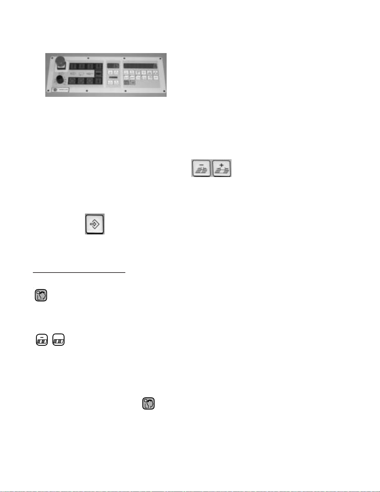
1. Press the Machine Setup button found in the top row.
..
2.
.Press the Sheet Gap
..
+ or - Buttons until P20 appears in the sheet gap display.
3. Press the Batch Count + Button until P25 appears in the sheet gap
display. You will now see the word “EASY” in the counter display
Batch Count + Button until P25 appears in the sheet gap display. You will now see the word “EASY”
in the counter display, see Figure E1.
Figure E1
TP10243-5 PAGE 12
Page 13
4. Look to the right hand end of the counter display. If an “ 1 “ appears in the display the Easy-
Parameter is turned on. If an “ 0 “ is displayed, the Easy-Parameter is turned off, see Figure E1.
To turn the Easy-Parameter on or off, Press the Plus (+) button for the batch
time delay setup. Pressing this button changes the “ 1 “ to an “ 0 “ and back. This button is found
at the far right side of the top row, see Figure E1.
5. Press the Machine Setup button again in the top row to confirm and exit pro-
gramming mode.
SELECT EASY MODE
Pressing this button enables the selection of either the EASY mode or cYcL mode
+
Pressing these buttons will toggle between the EASY mode or cYcL mode. Set EASY in
the large display. You will notice that the sheet gap display screen has (3) dashes when the
Easy Mode is on and a number when it is off.
Press the mode selection button again to exit mode selection.
PAGE 13 TP10243-5
Page 14

SELECT CONTINUOUS CYCLE MODE
It is recommended to use the continuous cycle mode when the job requires more than ½ of
the sheet length to go in the #1 fold plate or if the product has a window that will be sensed
as the trailing edge of the sheet.
The continuous cycle mode allows you to select the SHEET GAP, SHEET LENGTH and
the SUCTION LENGTH.
Pressing this button enables the selection of either the EASY mode or cYcL mode
+
Pressing these buttons will toggle between the EASY mode or cYcL mode. Set cYcL in the large
display (see figure E1).
SETTING THE SHEET GAP AND SHEET LENGTH
The small 3 digit display shows the current setting for the sheet gap. The number on the
right hand side of the large display (1) represents the current sheet length. Set the sheet
gap and sheet length for the current job.
SETTING THE SUCTION LENGTH
Use the + and – buttons under the 10 segment bar graph display to adjust the suction
length. Each segment represents 5% of sheet length. If 10 segments are illuminated 50%
of sheet length is selected. So, it is important that the sheet length is set properly for the
current job.
Press the mode selection button again to exit mode selection.
TP10243-5 PAGE 14
Page 15

TO START FEEDING
1. Press the GREEN Button to START the Folder Drive and the Pump.
2. Press the
Solenoid. The Sucker Wheel will pull a sheet from the Feeder onto the Register.
GREEN Button ABOVE the symbol to START the Vacuum
TO STOP FEEDING
1. Press the RED Button BELOW the symbol. This will turn the Vacuum
Solenoid OFF. The Sucker Wheel will STOP pulling sheets—BUT the Folder Drive and
the Pump will stay ON.
NOTE: You can also STOP feeding by Pressing the
RED PILE FEEDER STOP BUTTON.
CHANGE SPEED OF FOLDER DRIVE
To change the speed of the Folder Drive, just turn the Potentiometer Speed
adjust Knob on the Main Control Panel 1 thru 10, 10 being maximum speed
MACHINE PARAMETERS
Pressin Button allows access to the Machine Parameters. The Machine
Parameters may be monitored, some changed and various options (kicker, pile re-load,
etc.) enabled or disabled.
Navigation through the parameters is accomplished by using the following procedure:
1. Pressing and directly UNDER the 3 digit display will select
the various Parameters Groups by count of tens.
PAGE 15 TP10243-5
Page 16

EXAMPLE: Hold the MINUS Button, this will automatically count back to P00
(group P0). Now by Pressing the Button will take you to the next
Parameter Group P10 – P20 - P30 – P40 – P50 – P60
2. Pressing and directly UNDER the left 3 digits of the Large 8 digit
display, this will select the individual Parameters in a select group.
EXAMPLE: Start with the first Group of Parameters, the 3 digit
display reads P00. Pressing the this will take you to Parameters
P01 – P02 – P03 – P04 – P05
- To go to the next Group of Parameters Press
The display will show P10. Pressing the button
will take you to Parameters P11 – P12 –P13 – P14 (continue this sequence
to move thru the rest
of the Parameter Groups P20 – P30 – P40 – P50 – P60
3. To change one of the machines Parameter Settings Press or
Buttons UNDER the right most 2 digits of the large 8 digit display.
The following is a list of the available parameters. Please see the Operators Manual for a definition of each parameter.
TP10243-5 PAGE 16
Page 17

PAGE 17 TP10243-5
Page 18

To get out of the Machine Parameter Settings Mode, Press again. The displays will
ood
oo
o
return to normal operations.
BA TCH COUNTING SETUP
To enter Batch Count Set-Up, Press
1. This will bring up 3 display functions on the Control Panel.
First is the Small 3 digit display – this display must show
If the display shows any other Mode, the Batch Counter
will not function. To change, Press the or Buttons directly
UNDER the 3 digit display to change this Mode of Operation.
NOTE: If the display shows or the wrong batching device is
ooo
selected. These batching devices are Options not sold as standard equipment.
2. In the Large 8 digit display you will see 2 display functions.
1. Is the number of sheets in the batch.
2. Is the time delay between batches.
A. In the first 3 digits of the 8 digit display, this is the number of Sheets in each batch.
To adjust the number, press the or Button directly UNDER
the display until the desired number is displayed.
B. In the last 2 digits of the 8 digit display, is the time between batches
setting. This setting moves in Tenth (10th) of Seconds, to adjust, Press
TP10243-5 PAGE 18
Page 19
th e or Buttons directly UNDER the 2 digit display until the
desired delay number is displayed.
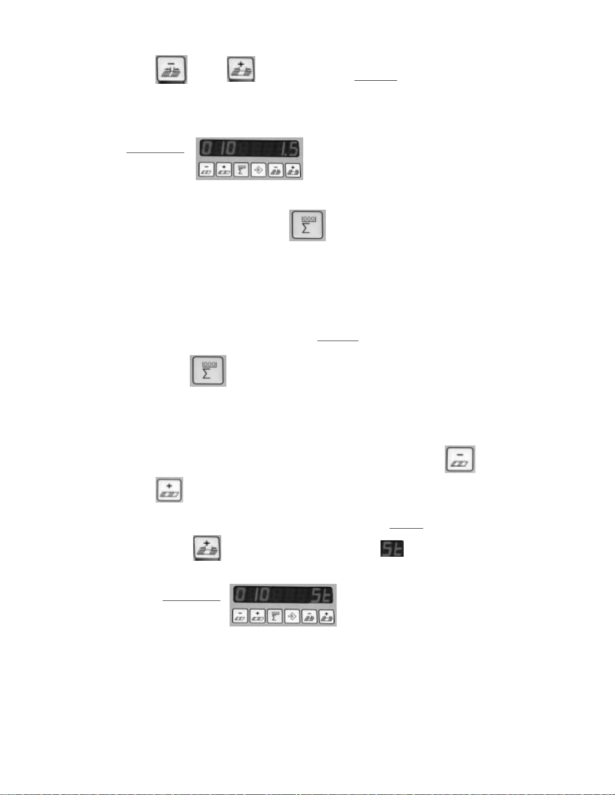
EXAMPLE:
This is set-up for 10 pieces in a Batch with a 1.5 second
delay between Batches.
3. To return back to RUN mode, Press Button and set either the Batch Size or
Time Delay to Zero and the Folder will run continuously.
STOP FEED
In Batch Count Mode, you also can have the Feeder Set-Up for a Stop Feed Count. You can enter
the number of Sheets that you wish to Feed and the Feeder will Feed that number and STOP.
The feeder will not Re-Start until you Press SHEET START Button.
1. Press the Button on the Control Panel, the 3 display functions on the
Control Panelwill appear.
A. In the first 3 digits of the 8 digit display enter the Number of
Sheets that you wish the Feeder to Feed by Pressing either
or Buttons.
B. In the Last 2 digits of the 8 digit display, Press and HOLD
th e Button until the LETTERS appears – the machine will
now Feed only the Number of Sheets that you have entered.
EXAMPLE:
With this setting the Feeder will run 10 sheets
and Stop Feeding.
PAGE 19 TP10243-5
Page 20

RESETTING THE TOTAL COUNTER
To reset the Total Counter, Press Button ; ensure the red LED is illuminated.
Press Button and HOLD DOWN for 3 SECONDS,
The Large 8 digit display will begin to Count BACKWARDS from 5.4.3.2.1,
then display CLEARED, the Counter is then ZERO.
You MUST Press and HOLD Button as the display is counting
BACKWARDS, if at anytime the ZERO Button is released, the Counter will
display the Last Count Value
NOTE The Batch counte r will also be reset to 0 by this procedure.
RESETTING THE BATCH COUNTER
Press the Batch counter Button ; ensure the red LED is illuminated.
Press Button and HOLD DOWN for 3 SECONDS,
The Large 8 digit display will begin to Count BACKWARDS from 5.4.3.2.1,
then display CLEARED, the Counter is then ZERO.
NOTE The Total counter will not be reset to zero.
TURN OFF BATCH COUNTING:
Press the counter setup button and set either the batch size or time dwell to zero.
Exit the counter setup mode by pressing the counter setup button again or any button in the second row.
TP10243-5 PAGE 20
Page 21
INSTALLING FOLD PLATES & STACKER
CORPORA
DELIVERY
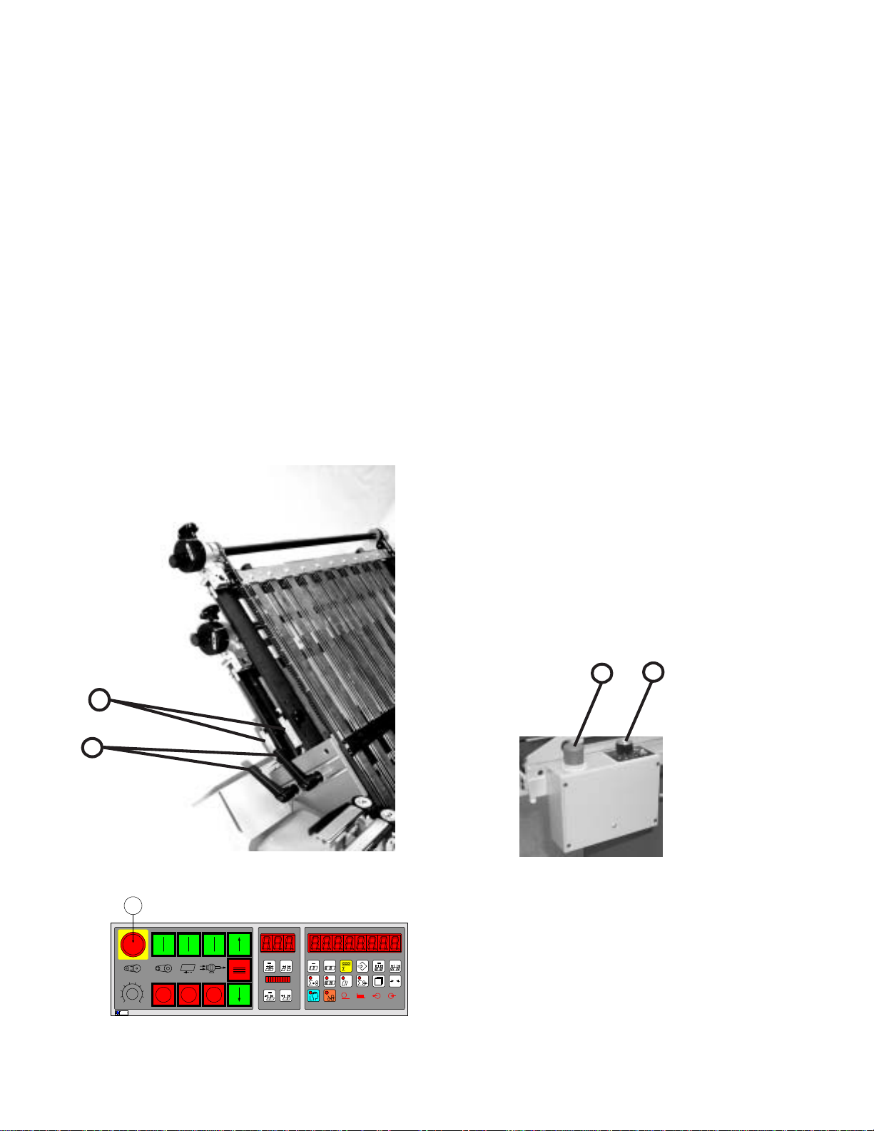
Install the fold plates into the folder. When installing
the fold plates, take note of the symbol on the fold plate stop
(Figure 7-1). The swing deflector may only be brought
forward when the deflector symbol is also in the forward
position. Lock the fold plates in position with the clamp
levers (7-2). See "Fold Pan" section for fold plate setting
procedure.
Attach the delivery stacker (3-2) by hooking the hanger
brackets onto the round rods at the exit end of the folder.
Plug the stacker power cable into the corresponding outlet
on the main control enclosure on the pile feeder (Figure 6-
1).
Pull the handwheel (Figure 1-11) to manually turn the
fold rollers to be sure that they are operating smoothly.
Check for any foreign material, and be sure that the deflectors do not touch the fold rollers.
OPERATOR CONTROLS
The main operator control panel (Figure 8) is located at
the pile feeder. See the "Control Panel" section for a detailed
description of all the buttons.
1.0 Setting Folding Speed
The speed of the fold rollers may be set while the folder
is running! This is done by adjusting the speed control
potentiometer located on the top left side of the main control
panel. Clockwise rotation speeds the folder up; counterclockwise rotation slows the folder down.
1.1 Setting Stacker Belt Speed
An infinite speed range between high and low is set by
turning the control knob (Figure 9-1).
1.2 Emergency Stop Button
When an emergency stop button (8-1 & 9-2) is pressed,
the result is:
Sheet feed - stop
Folder drive - stop
Pile lift - stop
The pressure/vacuum pump continues to operate. The
emergency stop button must be pulled to release before the
machine can be restarted. An error message "StoP" will
appear on the readout.
The emergency stop buttons are found at the main
operator control panel (8-1) and the delivery control (9-2).
1
2
Figure 7
1
56
4
7
3
8
2
9
1
10
BAUMFOLDER
CORPORA
TION
Figure 8
2
1
Figure 9
+
+
+
h
+
0
PAGE 21 TP10243-5
Page 22

1. 0 Control Panel BAN-5
56
4
3
2
1
BAUMFOLDER
CORPORATION
7
8
9
10
36
9 13 11 16 26 27 22 23 4 5 7 615 3
Figure 1. Control Panel.
25 2824 28 12 10 1417
+
+
1 29 30 31 32 33
+
h
18 19 20 21 34 35
+
0
1.1 Displays
01) Large Display
Eight digit multi use display composed of 7segment LED’s.
02) Small Display
Three digit multi use display composed of 7segment LED’s.
03) Ten segment bar graph display
The suction length display is used to display the
Suction Length as a percentage of Sheet Length.
This allows a range from 5% to 50%.
1.2 Machine Status Indicators
04) Suction Indicator
The suction indicator will track the suction
output. The LED will turn on when the suction
output turns on.
05) Pile indicator
The indicator is lit when the feeder is in automatic feed mode. The indicator will flash if the
feeder is in reverse mode (Continuous Feeder) or
moving down (Pile feeder)
06) Input Indicator
The input indicator shows the status of the suction
photo-eye.
07) Output Indicator
The output indicator lights when the Batch Preset
is reached and the user has selected a batching
option. The output indicator is lit during the time
the batching option is active.
Batching options are Feed interruption, Speed up
table, Marking table or Kicker.
1.3 Machine Control Pushbuttons
08) Main Drive Start
09) Main Drive Stop
10) Pump Start
11) Pump Stop
12) Feeder Start
13) Feeder Stop
14) Pile Feeder Up, Continuous Feeder Start
15) Pile Feeder Stop, Continuous Feeder Stop
16) Pile Feeder Down, Continuous Feeder Reverse
17) Emergency Stop
TP10243-5 PAGE 22
Page 23

1.4 Keypad Buttons with Selection Indicators
18) Show Output Count
19) Show Batch Count and Number of Batches
20) Show Current Rate
21) Show Input Count
22) Learn Mode
23) Make Ready Mode
1.5 Keypad Buttons for Selection Adjustment
24) Gap Minus
25) Gap Plus
26) Suction Length Minus
27) Suction Length Plus
28) Batch Preset Minus
29) Batch Preset Plus
30) Counter Setup Mode
31) Machine Setup Mode
32) Batching Time Minus
33) Batching Time Plus
34) Network Job Mode
35) Reset
36) Potentiometer Speed adjustment
2. 1 Machine Setup/Diagnostic Mode
Pushing this key puts the controller in machine setup
mode.
Machine setup mode provides a method to view and
optionally change operating parameters for the controller.
The decimal points in the large display (1) will move from
side to side to indicate that various parameters may be
changed. In this mode, the small display gives the selected
parameter number, while the large display (1) shows a
parameter value. The suction length display (3) is disabled.
Parameter Group Selection
+
The plus and minus keys are used to select the various
parameter groups: machine setup parameters, machine
monitor parameters, machine diagnostic parameters, knife
status parameters, and machine usage parameters.
Parameter Selection within a Group
+
2.0 Run Mode Functions
After turning on the main switch, the control automatically runs a self test. During this self test all displays and
indicator lights come on for approxmately 4 seconds. After
a successful self test, the display reverts to the previous
count screen active before power shutdown. In this mode,
various job parameters can be displayed on the large display
(1) and the small display (2) shows the gap length. The
suction length display (3) is active in this mode and shows
the suction length as a percentage of sheet length.
The DCT500 mode select keys perform the same
function in all modes, except Counter Setup. This allows a
user to quickly switch between the operating modes on the
counter. Select Make-Ready is not a mode unto itself, but
rather is a modifier to all modes.
During the self test operation, do not press any
button. Pressing of a button will cause an error
message to appear in the main display.
!
If the large display (1) decimal points are moving, this
set of minus and plus buttons will select the machine
parameters within each group, see tables 1-6.
Select Parameter Adjustment
+
If the large display (1) decimal points are moving, this
set of minus and plus buttons will move through the set of
values for the selected parameter, see tables 1–6.
PAGE 23 TP10243-5
Page 24

2.1.1 Machine Setup Parameters
Parameter Function Type Variable Displayed
P00 Input Factor Setup Variables Adjustable 1-24
P01 Output Factor Setup Variables Adjustable 1 to Input Factor
P02 Tremat Setup Variables Adjustable 1 or 0
P03 Knife Setup Variables Adjustable 1 or 0
Table 1. Machine Setup Parameter List
P00: Input Factor
Each sheet sensed by the Sheet count sensor is multiplied by the Factor number and added to theTotal Input
Count, but does not effect the Batch Down Count, Number
of Batches or the Rate. The Factor can range from 1 to 24. If
the Input Factor is changed, it also changes the value of the
Output Factor to the same setting.
P01: Output Factor
This number is added to the Total Output Count but
does not effect the Batch Down Count, Number of Batches
and the Rate. The Factor can range from 1 to Input Factor
setting.
2.1.2 Machine Monitor Parameters
# Function Type Variable Displayed
P10 Machine Speed Process Variable Based on input Meters/Minute
P11 Job Run Time Process Variable Based on input Hours
P12 Job Stop Time Process Variable Based on input Hours
P13 Job Make Ready Time Process Variable Based on input Hours
P14 Pause Time Process Variable Based on input Hours
P15 Job Number Process Variable Based on Input Number 1 - 9999
P16 Employee’s Number Process Variable Based on input 1 - 255
P02: Tremat
This is an unavailable option.
P03: Knife
This is an unavailable option.
Table 2. Machine Monitor Parameter List
P10: Machine Speed (Velocity)
This selection shows the machine speed in meters/
minute.
P11: Job Run Time
Displays the time duration this job has ran. Time
displayed in .01 Hours. This information becomes part of the
job record.
P12: Job Stop Time
Display the time duration this job has been interrupted.
Time displayed in .01 Hours. This information becomes part
of the job record.
P13: Job Make Ready Time
Displays the length of time that the Make Ready
feature was enabled. Time displayed in .01 Hours. This
information becomes part of the job record.
TP10243-5 PAGE 24
P14: Pause Time
Display the length of time that the Job was Paused.
Time displayed in .01 Hours. This information becomes part
of the job record.
P15: Job Number
A Job Number may be entered so that production
data may be recorded against it. This is an operator entry.
This information becomes part of the job record.
P16: Employee’s Number
An Employee may be assigned a number. When
the employee operates the machine, his number may be
entered. This information becomes part of the job record.
Page 25

2.1.3 Machine Setup Parameters
# Function Type Variable Displayed
P20 Units of Measure Setup Variables Adjustable Inches, Meters
P21 Language Setup Variables Adjustable English, German, Codes
P22 Network Address Setup Variables Adjustable 0-255
P23 Pause Setup Variables Adjustable 1 or 0
P24 Network Setup Variables Adjustable 1 or 0
P25 Easy Setup Variables Adjustable 1 or 0
P26 Software Version Machine Configuration Fixed V X.X.X
P27 Machine Type Machine Configuration Fixed Set at Factory
P28 Serial Output Type Machine Configuration Fixed Off, Display, or Network
Table 3. Machine Setup Parameter List
P20: Units of Measurement
This selection specifies the unit of measurement used to
display all lengths. Inches (SAE) is the default selection.
Available choices are Meters (measurement displayed in cm)
and Inches (measurement displayed in inches and tenths of
inches).
P21: Language
This selection specifies the Language used to display
fault messages. Available choices are ENGLISH,
DEUTSCH, and CODES, see Tables 16–18, Error Message
Translation. English is the default selection.
P22: Network Address
This selection specifies the unit address used for
Network communication. Available choices are 0 through
255. Address 0 is the default selection. Network functions
are not available in software version 3.0.1
P23: Pause
P24: Network Enable
Network components must be installed and enabled in
Maintenance Mode. Enable Network by selecting “1”.
Disable network by selecting “0”.
P25: Easy Mode
Enable Easy Mode by selecting “1”. Disable Easy Mode
by selecting “0”.
Easy Mode has two sheet control methods, Easy setup or
Continuous cycle. Easy setup will run any job with a 1 inch
sheet gap. The sheet gap display contains 3 dashes and the
Suction Length bar graph is turned off.
In Continuous cycle setup, the suction cycle is determined by
the sheet gap setting, sheet length setting and the suction
length setting. Sheet error detection methods are turned off.
P26: Hardware and Firmware Version
This selection shows the hardware and firmware
versions of the unit. The left side of the display shows logic
board type. The right side of the display shows the firmware
version (3.X.X).
P27: Machine Type
This selection, in maintenance mode, shows the selected
machine configuration.
P28: Serial Output Type
This selection, in maintenance mode, shows selected
serial output type.
PAGE 25 TP10243-5
Page 26

P28: Serial Output Type
This selection, in maintenance mode, shows selected
serial output type.
2.1.4 Diagnostic Parameters
P30 Status Input Port 1
P30.1 P30.2 P30.3 P30.4 P30.5 P30.6 P30.7 P30.8
Pile Motor Function Pile Down Pile Stop Pile Up Compress. Compress. Drive Start
Energized Control K1 Button Button Button Stop Button Start Button Relay K3
P31 Status Input Port 2
P31.1 P31.2 P31.3 P31.4 P31.5 P31.6 P31.7 P31.8
Pile Sensor Double Pile Sheet Start Sheet Stop Thermal Wrong Sheet Emerg.Stop
Sheet Fault Bottom Button Button Fault Fault Drive Stop
P32 Status Input Port 3
P32.1 P32.2 P32.3 P32.4 P32.5 P32.6 P32.7 P32.8
Ergonomic Not used Not used Not used Not used Suction Delivery Photo eye
Pile Load Controller Count Input Suction
Eye Fail Wheel
P33 Status Input Port 4 (Extension Port)
P33.1 P33.2 P33.3 P33.4 P33.5 P33.6 P33.7 P33.8
Not used Not used Not used Not used Not used Not used Not used Not used
P34 Status Output Port 1
P34.1 N P34.2 P34.3 P34.4 P34.5 P34.6 P34.7 P34.8
Not used Not used Not used Not used Pile Down Pile up Release Compress
P35 Status Output Port 2 (Extension Port)
P35.1 P35.2 P35.3 P35.4 P35.5 P35.6 P35.7 P35.8
Not used Not used Not used Not used Not used Not used Not used Not used
Button
is active is active Drive Start Start (K4)
Table 4. Machine Diagnostic Parameter List
P30: Input Port 1 Status
P31: Input Port 2 Status
P32: Input Port 3 Status
P33: Input Port 4 Status (Extension)
This selection shows the inputs status(see table4).
P34: Output Port 1 Status
P35: Output Port 2 (Extension)
This selection shows the outputs status (see table 4).
2.1.5 Future Features
# Function Type Variable Displayed
P40 Last Knife Eye Time 1 Not used Not used Not used
P41 Last Knife Eye Time 2 Not used Not used Not used
P42 Last Knife Eye Time 3 Not used Not used Not used
P43 Strokes knife 1 Not used Not used Not used
P44 Strokes knife 2 Not used Not used Not used
P45 Strokes knife 3 Not used Not used Not used
Table 5. Future Features List
TP10243-5 PAGE 26
Page 27
2.1.6 Machine UsageStatus Parameters
# Function Type Variable Displayed
P50 Power on time Machine Status Based on Inputs Time in 1/100 Hours
P51 Machine run time Machine Status Based on Inputs Time in 1/100 Hours
P52 Total Input Sheets Machine Status Based on Inputs Number in 1000 Sheets
Table 6. Machine Usage Status Parameter List
P50: Power On Time
This selection shows the time in 1/100 hour during the
main switch of the machine is on.
P51: Machine Run Time
This selection shows the time in 1/100 hour during the
main drive contactor of the machine is on.
P52: Total Input Sheets
This selection shows the total input counts in 1000
sheets
Exit Machine Setup and Diagnostic Mode
0
h
Pressing any of these keys will cause the controller to
change to a new mode.
2.2 Counter Setup Mode
Pushing this key puts the counter in counter setup
mode.
The speed up-table output activates the marking table
output for the batching time duration.
The MKE mode is an unavailable option.
The kicker is a future feature.
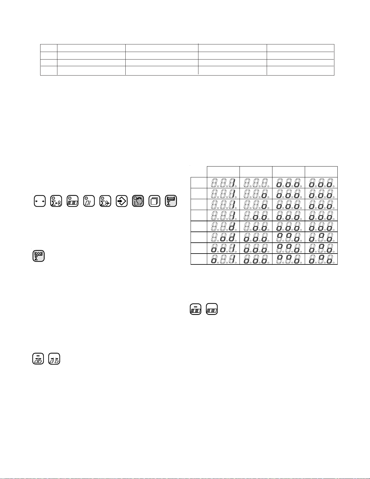
The output types are represented by animated symbols.
The sequence of frames for the animations is shown in
table 7.
Feed Interruption Speed Up Table MKE Table Kicker
Frame
1
Frame
2
Frame
3
Frame
4
Frame
5
Frame
6
Frame
7
Frame
8
Not
Available
Future
Feature
Table 7. Output Type Animations
Counter setup mode is used to prepare the controller to
run a job. The large display (1) shows the batch preset on
the left-hand side and the batching output time on the right
hand side. The decimal points in the large display (1) will
move from side to side to indicate that a parameter may be
changed. The small display (2) shows the batching type. The
suction length display (3) is active.
Change Batching Type
+
The minus and plus buttons move through a list of four
output devices. The chosen Type is then activated when the
batch down-count goes to zero. Feed interruption stops the
feeding of sheets for the batching time setting.
Batch Preset Adjustment
+
These buttons cause the batch preset value to increment or
decrement. The preset will be reloaded after the user leaves
the setup mode only if the value has been changed.
PAGE 27 TP10243-5
Page 28

Batching Time Adjustment
+
The batching time adjustments allow the user to select
the time duration associated with the currently selected
output type. Two output types and times are available.
1. Feed interrupt has a range of 0.0 to 9.9 seconds.
2. Speed-up Table has a range of 0.00 to 5.00 seconds.
Select Count Source
The Output Count and Input Count keys select between
count at delivery and feeder, respectively. One key LED
will always be lit in Counter Setup to show the current
count source, see table 8. Chasing LEDs will activate in
the small display signifying the start setup mode. The next
sheet fed through will be timed from leading edge to
trailing edge and the delay time will be set to one half the
sheet time. Please note this must be redone if the delivery
speed is changed.
+
Pressing these buttons will toggle between the EASY
mode or cYcL mode. Set EASY in the large display and
press again.
Select Continuous Cycle Mode
Pressing this button enables the selection of either the
EASY mode or cYcL mode
+
Pressing these buttons will toggle between the EASY
mode or cYcL mode. Set cYcL in the large display and
.press again.
Exit Run Mode
The batching count source will be the feeder
photoeye.
The batching count source will be whatever is
connected as the delivery photoeye.
Table 8. Count Source Selection
Exit Counter Setup Mode
Pressing any of these keys will cause the counter to
change to a new mode.
0
2.3 Easy Mode and Continuous Cycle
Mode
2.3.1 Easy Mode and Continuous Cycle Mode
Pressing any of these keys will cause the counter to
change to a new mode.
2.4 Learn Mode
This key places the controller in learn mode. Learn
mode can only be activated if the folder is idle.
The learn mode allows the user to setup the suction
valve controller. Both manual and automatic setup is
accomplished in this mode. The large display (1) shows
two separate data items. The suction mode is shown on the
left and the sheet length is shown on the right. The small
display (2) shows the current gap length. The suction
length display is active. During Learn Mode, the Learn
Mode key LED indicates whether a valid sheet has been
learned.
No valid sheet has been read yet, t he system i s in
Single Sheet mode.
A vali d sheet has been read and the DCT500 has
been setup to run. Single Sheet mode is of f.
Job
Enable EASY mode at parameter P25, see Table 3.
Select Easy Mode
Pressing this button enables the selection of either the
EASY mode or cYcL mode.
TP10243-5 PAGE 28
Table 9. Learn Mode Status
When the LED is on, pushing the sheet start button will
feed a single sheet of paper. If the sheet is fed properly, the
indicator LED will go off. The suction mode will be set to
automatic. The length of the sheet will be set as the current
sheet length. The suction length will be set based on table
11 and the gap length will be set to 4 cm /1.50 inches.
Page 29
l
If P06 is set to 0 (no knife is active) and 10 cm /4.0 inches. If
P06 is setting to 1, knifes are active.
Gap Length Adjustment
+
The minus and plus keys adjust the gap length. The gap
length range is 0.2” to 98.0” (0.5cm to 250cm).
Suction Length Adjustment
+
This is the same as in run mode
Select Suction Mode
+
These keys toggle between automatic control and cycle
mode. In the cycle mode, the suction valve will be on for
the suction length and off for the remainder of the sheet
length plus the gap length. No adjustments are made for
slipped sheets or process changes. The automatic mode
corrects for process changes and controls the timing of the
suction valve to maintain the user-selected gap. If the gap
is less than 1.5” (4.0 cm), the right hand decimal point of
the small display (2) will flash and the Leading edge
control will be active. If the gap is greater than or equal to
1.5” (4.0 cm), full Leading and Trailing edge control is
maintained. Refer to table 10 for suction mode symbol
definitions.
The suction length adjustment keys allow the user to
change the amount of suction applied to the current sheet
length. The display shows the percentage in 5% steps. All
of the bars must be totaled to get the value. The range of
adjustment is 5% to 50% of the current sheet length. If the
suction length is manually adjusted while the Learn Mode
LED is on, the suction length will no longer be the Single
Sheet suction length of 6.0”. The new suction length will
be based on the current sheet length and suction setting.
TWT-180 Mode
Leading Edge Control
Leading and Trailing Edge Contro
Table 10. Suction Mode Symbols
Sheet Length Setting Resultant Suction Length Percentage
Greater than or equal to 30 cm. 30% of Sheet Length
Less than 30 cm., and greater than or equal to 27 cm. 25% of Sheet Length
Less than 27 cm., and greater than or equal to 24 cm. 20% of Sheet Length
Less than 24 cm., and greater than or equal to 21 cm. 15% of Sheet Length
Less than 21 cm. 10% of Sheet Length.
Table 11. Suction Length Function
Sheet Length Adjustment
+
The sheet length adjustment keys allow the user to
override the automatic Learn Mode setting. When the user
changes the sheet length, the suction length will be
adjusted according to table 11. If a different suction length
is desired, the value may be overridden with the suction
length adjustment keys. The sheet length range is 10 cm /4
inches to 250 cm / 98.5 inches.
Exit Learn Mode
0
h
Pressing any of these keys will cause the controller to
change to a new mode.
2.5 Make Ready Mode
This key places the controller in the make ready mode.
The key LED goes on. In this mode the folder will only
feed single sheets and a batching output is issued for every
two sheets fed. This allows the operator to easily set up the
batching time.
PAGE 29 TP10243-5
Page 30
Exit Make Ready Mode
2.7 Production Mode
Enter Run Mode and Select Large Display Content
h
Pressing any of these keys will cause the controller to
change to a new mode.
0
2.6 Network Job Mode
Pushing this key puts the counter in network job mode
+
This mode is only available if a STA-NET adapter is
installed and activated through maintenance mode. In this
mode the small display (2) always shows the word ‘Job’.
The large display (1) shows either ‘PAuSE’ or a job
number which can be read from the network. The suction
length display is disabled.
Select Job Number
+
This set of plus and minus keys step the large display
(1) through pause mode and a list of available job numbers.
While in network job mode, the folder is considered to be
paused.
Load Job and Return to Run Mode
When this button is pushed the selected job will be
loaded into the counter and the counter will return to run
mode. If the large display (1) was showing the message
‘PauSE’, the network job mode will end, but no job will be
loaded.
Exit Network Job Mode
+
+
h
These keys do not operate as mode select keys in
counter setup. In all other modes, the keys both select the
large display (1) contents and place the counter into run
mode. Pushing one of the buttons will light the button’s
associated LED and cause the parameter to be displayed. If
both the input and output count keys are pressed simultaneously, then both LEDs go on and the waste count is
displayed. See Process Variable Definitions.
Large Display Contents
h
h
h
h
h
Table 12. Determining the Large Display Contents
h
When the folder is started the counter will start up in
the run mode, the normal operating mode of the counter.
In this mode, various job parameters can be displayed on
the large display (1) and the small display (2) shows the
gap length. The suction length display (3) is active in this
mode and shows the suction length as a percentage of sheet
length.
Output Count
Batch Count Down
Number of Batches
Current Rate
Input Count
Waste Count
Gap Length Adjustment
+
h
Pressing any of these keys will cause the counter to
change to a new mode.
TP10243-5 PAGE 30
The gap length adjustment keys allow the user to
change the current gap length. The range of adjustment is
0.2” to 98.0” (0.5 cm to 250 cm).
Suction Length Adjustment
+
The suction length adjustment keys allow the user to
change the amount of suction applied to the current sheet
length. The display shows the percentage in 5% steps. All
of the bars must be totaled to get the value. The range of
adjustment is 5% to 50% of the current sheet length.
Page 31

Reset Function
0
Pressing and holding this key will result in a reset
function being activated after a 5-second countdown. The
function is based on the current large display selection, see
table 12. The large display (1) will show countdown to
reset in this manner. When the button is pressed the
message ‘CLr In 5’ will show on the large display (1). At
one second intervals the display will progress through ‘CLr
In 4’, ‘CLr In 3’, ‘CLr In 2’, ‘CLr In 1’, and finally will
show ‘CLEArEd’ when the reset action is complete.
3. 0 Logic Board Status Indicators
Several of the controller functions are monitored with
LED indicators located on the Logic Board (see Table 14).
The status of all other inputs are shown on the 8 Digit
display in Machine Setup mode (see Tables 1 - 6).
Reference Name Description
Designator
LED1 Tachometer Indicator Tracks the Tachometer input.
LED2 Not Used Turns on when MKE output is activated.
LED3 Suction Indicator Tracks the Suction output.
LED4 K1 Status of Relay K1
LED5 Pile Down Tracks the Pile down output.
LED6 Pile Up Tracks the Pile up output.
LED7 Pile Indicator Tracks the Pile outputs. If one of the Pile
LED8 Logic +5VDC Supply Shows status of Logic +5VDC Supply
LED9 Isolated +5VDC Supply Shows status of Isolated +5VDC Supply
LED10 Isolated +24VDC Supply Shows status of Isolated +24VDC Supply
LED11 Kicker Turns on when kicker output is activated.
Table 14. LED Status Indicators
Reset while showing Output Count will reset all job
variables.
Reset while showing batch data will reset Number
of Batches and reload the Batch Down Count.
Table 13. Reset mode Selection
outputs is on, this LED will be on.
PAGE 31 TP10243-5
Page 32

4.0 Process Variables Definitions
4.1 Total Input Count
The Current Rate is rounded to the nearest hundreds.
Current Rate can range from 0 to 99,999,900.
This process variable is not stored in memory.
Total Input Count increments by the factor setting each
time an input is received at the Input Count input. Total
Input Count can range from 0 to 99,999,999.
This process variable is stored in memory in case of a
power outage.
Reset job will clear this process variable to zero.
4.2 Total Output Count
Total Output Count increments by the factor setting
each time an input is received at the Output Count input.
Total Output Count can range from 0 to 99,999,999.
This process variable is stored in memory in case of a
power outage.
Reset job will clear this process variable to zero.
4.3 Batch Down Count
The Batch Down Count is the number of remaining
inputs necessary to trigger a batch output. As input counts
are received, this value counts down to zero. Each input
decrements the Batch Count Down by one. When zero is
reached, the Batch Down Count resets to the Batch Preset.
The Count input that is used by the Batch Down Count is
determined by the Batching Selection in Machine Setup. If
Feeder is the Batching Selection, the Batch Down Count
will be affected by the Input Count Input. If Delivery is the
Batching Selection, the Batch Down Count will be affected
by the Output Count Input.
Batch Down Count can range from 1 to 999.
This process variable is stored in memory in case of a
power outage.
Reset job will clear this process variable to zero.
Reset batch will load this process variable with the batch
preset.
4.4 Number of Batches
The Number of Batches is the number of times the
Batch Down Count has reached zero.
Number of Batches can range from 0 to 9999.
This process variable is stored in memory in case of a
power outage.
Reset job will clear this process variable to zero.
Reset batch will clear this process variable to zero.
4.5 Current Rate
The Current Rate is based on the number of Input
Count inputs received during the sample period.
The Current Rate is calculated every second.
The Current Rate is shown as rate per hour
4.6 Main Drive Run Time
The Main Drive Run Time is the amount of time the
Drive output has been on since the last Clear All Memory
Reset in Maintenance Mode.
This value is displayed in the format HHHHHH.HH.
Main Drive Run Time can range from 0.00 to 999,999.99.
This process variable is stored in memory in case of a
power outage.
Reset ALL in maintenance mode will clear this process
variable to zero.
4.7 Main Drive Velocity
The Main Drive Velocity is the speed of the Tachometer input.
This value is displayed in meters per minute.
This value is calculated every 300 milliseconds.
This process variable is not stored in memory.
4.8 Waste Count (Option)
The Waste Count is the difference between the Total
Input Count and the Total Output Count.
Waste Count is accessible by pressing and holding the Total
Count button followed by pressing the Total Output Count
button.
Waste Count can range from 0 to 99,999,999.
This process variable is not stored in memory.
Reset job will clear this process variable to zero.
5.0 Counter Setup V ariables
5.1 Batch Preset
This parameter, accessible in the Batch Setup mode,
specifies the batch count that will be used by the Batch
Count Down. Zero is the default setting.
This value can range from 0 to 999.
5.2 Batch Output T ype
This parameter, accessible in the Batch Setup mode,
specifies the batch output type that will be used when the
Batch Count Down reaches zero.
Available choices are Feed (FED), Delivery (DEL), Speed
(SPD), and Table (TBL).
TP10243-5 PAGE 32
Page 33

5.3 Batch Output Time
This parameter, accessible in the Batch Setup mode,
specifies the output duration or delay that will be used when
the Batch Count Down reaches zero.
Available ranges are determined by the Batch Output Type
selected. The Table below shows the ranges for each output
type.
Output Delay Duration
Type Min. Time Max. Time Min. Time Max. Time
Feed Not applicable 0.0 Sec. 9.9 Sec.
Table 0.000 Sec. 1.000 Sec. 100 ms
Delivery 0.000 Sec. 1.000 Sec. 25 ms
Speed Not applicable 0.00 Sec. 5.55 Sec.
Table 15. Output Delay and Duration
5.4 Sheet Length
This parameter, accessible in the Batch Setup mode,
specifies the length of the paper that will be fed into the
machine.
Available range is 6.0” to 59.0”. 6.0” is the default
selection.
5.5 Gap Length
This parameter is accessible in Run mode and Learn
mode and specifies the length of gap to use between sheets
of paper that are fed into the machine.
Available range is 0.2” to 98.0”. 2.0” is the default selection.
5.6 Suction Length
This parameter is accessible in Run mode and Learn
mode andspecifies the suction length used on a sheet of
paper that is fed into the machine.
Available range is 5% to 50% in 5% increments. 30% is the
default.
PAGE 33 TP10243-5
Page 34

6.0 System Messages and Run Messages
6.1 Power-Up Fault Messages
Messages that are displayed during power on self-test. If PLC System Errors are shown in the display, call service.
ENGLISH GERMAN CODES TYPE DESCRIPTION
88888 88888 88888 Information The controller is performing its lamp test.
MEM TEST MEM TEST MEM TEST Information The controller is performing its RAM test.
All Blank All Blank All Blank PLC System The display board is not functioning.
Error Cycle Power. If error persists, call service.
ID Fail ID Fail ID Fail PLC System System cannot recognize the controller board.
Error Action: Cycle Power, if error persists call service.
Error 1 Error 1 Error 1 PLC System The RAM test has found a bad memory location.
Error Action: Cycle Power, if error persists call service.
Error 2 Error 2 Error 2 PLC System The Pile Safety Relay is stuck on or there is no power supply to the
Error pile circuits. Action: Check the condition of Relay 1 (K1), Fuses
F1 and F2, and X18. Cycle Power. If error persists, call service.
Error 3 Error 3 Error 3 PLC System There is power in the Pile Drive when it is off. Action: Check the
Error condition of Relay 1 (K1), Fuses F1 and F2, and X18. Cycle
Power. If error persists, call service.
Error 4 Error 4 Error 4 PLC System The 24VAC inputs have current before the Watchdog relay has
Error been activated. Action: Check for stuck push buttons, faulty
sensors, or loose connectors. Cycle Power. If error persists, call
service.
Error 5 Error 5 Error 5 PLC System The membrane switch panel has a key pressed during the power
Error on self-test. Action: Cycle Power, if error persists call service.
Error 6 Error 6 Error 6 PLC System The Watchdog sense circuit indicates Watchdog-timer operational
Error before it has been started. Action: Cycle Power, if error persists
call service.
Table 16. Power Up Fault Messages
TP10243-5 PAGE 34
Page 35

6.2 Run Time Fault Messages
Run time fault messages are only displayed when the unit is in Run mode. Fault errors can still occur, but the corresponding
fault message will not be displayed until the unit is switched to Run mode. Run time fault messages are PLC System Errors
or errors in the whole Electric System. It is necessary to call a technician or service.
ENGLISH GERMAN CODES TYPE DESCRIPTION
DCT X.X.X DCT X.X.X DCT X.X.X Information This is the Software-Version(X.X.X)
Note: do not push any buttons until this message has been
cleared from the display
K5 Relay K5 Relay Error 7 PLC System The drive stop relay, K5, is not responding to the controller.
Error Action: Call service.
Button Taste Error 8 Electrical A push button is in the wrong state during the version message
System display. Action: Check Buttons & Cycle Power. If error
Error persists call service.
Watchdog Watchdog Error 9 PLC System The Watchdog Timer has elapsed without being serviced.
Error Action: Cycle Power. If error persists call service.
No Tach Impuls Error10 Electrical The Machine Tachometer is reading a velocity outside of the
System range 10 – 230 meters per minute, while the main drive should
Error be running. Action: Check the electric. If error persists call
service.
Overload Uberlast Error11 Electrical A Thermal Overload has been tripped.
System Action: Check the electric. If error persists call service.
Error
Pile Err Spg.Uber Error12 Electrical The Pile Safety Relay is stuck on or there is no power supply to
System the pile circuits. Action: Check the condition of Relay 1 (K1),
Error Fuses F1 and F2, and X18, then cycle Power. If error persists
call service.
Overrun Uberlauf Error13 Electrical The Pile Table has moved past its safety stops. Action: Check
System the limit switches, pile table, and wiring. If error persists call
Error service.
2nd Stat 2Station Error14 Electrical The Emergency Stop, Wrong Sheet, and Thermal Overload
System sense circuits are all indicating failure. Likely cause is Second
Error Station connector problems. Action: Check the Second Station
Connector, connector X22, and each individual circuit. If error
persists call service.
Suction Saugtakt Error15 Electrical Short circuit on Suction controller. Action: Check the electrics.
System If error persists call service.
Error
Table 17. Run Time Fault Messages
PAGE 35 TP10243-5
Page 36

6.3 Machine Run Error Messages
Machine Run Error Messages help the operator to indicate a production problem.
ENGLISH GERMAN CODES TYPE DESCRIPTION
Stop Stop1 Stop1 Information One of the stop buttons is depressed. ACTION: Make sure all
stop buttons are cleared and connectors X21, and X22 are
seated.
Wrng Sht Fehlerbg Stop2 Machine The Wrong Sheet Detector has been tripped. ACTION: Clear
Run Error the fault. NOTE: If the main drive was running, the error
condition will remain latched until the Drive START is pressed.
2 Sheet Doppelbg Stop3 Machine The Double Sheet Detector has been tripped. ACTION: Clear
Run Error the fault and check X22. NOTE: If sheet feed was active, the
error condition will remain latched until the Sheet Start is
pressed.
No Feed Bog.Fehl Stop4 Machine No paper detected within 40 cm of suction valve actuation,
Run Error while running in an automatic feed mode. ACTION: Check
misfeed, connector X14, and the condition of the count photoeye.
Feeder Sensor Stop5 Machine Photo-eye at suction valve is covered before Sheet Start is active.
Run Error
Long Sht Bg.Lang Stop6 Machine The count photo-eye has been covered for more than 150% of
Run Error the user set sheet length distance. ACTION: Check misfeed,
connector X14, and the condition of the count eye.
Knife 1 Schwert1 Stop7 Machine The knife input 1 has been active for more than 1.5 times the
Run Error last measured time. ACTION: Clear the fault.
Knife 2 Schwert2 Stop 8 Machine The knife input 2 has been active for more than 1.5 times the
Run Error last measured time. ACTION: Clear the fault.
Knife 3 Schwert3 Stop 9 Machine The knife input 3 has been active for more than 1.5 times the
Run Error last measured time. ACTION: Clear the fault.
Snsor DN Stpl Ab Stop 10 Machine The Pile has been moving down for more than 2.5 seconds
Run Error while the unit is feeding paper. ACTION: Check Pile Sensor.
Snsor Up Stpl Auf Stop 11 Machine The Pile has been moving up for more than 1.5 seconds while
Run Error the unit is feeding paper. ACTION: Check Pile Sensor.
Table 18. Machine Run Error Messages
TP10243-5 PAGE 36
Page 37

PILE FEEDER OPERATION
1.0 Loading the Pile Feeder
Set the right hand side guide (Figure 11-1) to half the
sheet using the scale (11-2). The vacuum wheel is in the
center of the sheet. Lock the guide in place using the lever
(11-3).
Remove the left hand guide (Figure 12-4) from the
feeder. Move the sheet drag guide block (12-5) on the righthand guide to the rear of the paper stock.
Press the table down button (for controls, see page 8). A
lower limit switch will halt the pile table when it descends
to the lowest position. Load the paper against the front and
right hand guides (11-1).
Press the table up button. The pile height sensor (11-6)
will stop the upward travel of the table. During operation,
the top sheet of the pile should be approximately 1/2" under
the vacuum wheel and 5/8" under the sensor (11-6), with
the pile up and the pump off. The pile height sensor is
contact-free.
Reinstall the left hand guide (12-4). Slide the register
guide (12-7) inward until the see-through left hand guide
(12-4) is approximately 1/16" away from the stack.
6
Figure 11
2 4
3
1
1.1 Hold-down Locations1.1 Hold-down Locations
1.1 Hold-down Locations
1.1 Hold-down Locations1.1 Hold-down Locations
Set the sheet hold-downs so the rubber bumpers rest on
top of the sheet pile and prevent double sheets from being
pulled in. Using the rubber bumpers is dependent upon the
stock being fed.
1.2 Air and Vacuum Settings
Press the pile up button if it has not been pressed.
Press the pump "on" button.
Adjust the air flow into the top of the stack as shown in
Figure 13, using the blow tube angle levers (Figure 14-1)
and the air bleed off valve cover (14-2).
Figure 13 shows that the top four to five sheets are to be
separated using the top blow tube (13-1). The bottom blow
tube (13-2) separates approximately 1/2" of the stack under
the top four or five sheets. The bottom blow tube (13-2)
provides separation to send sheets up to the top to be fed.
Do not adjust the air angle flow too high into the
sheets. The top sheets should be in a humped pattern as seen
through the side guide for approximately 75% of the sheet
length.
7
Figure 12
Figure 13
4
2
1
5
Figure 14
PAGE 37 TP10243-5
Page 38

1.3 FRONT BLOW TUBE SETTINGS
The front blow consists of two tubes (Figure 13-1 & 2
and Figure 15-1 & 2) instead of the traditional one tube.
The numbers on the left hand side of the tubes correspond to
the chart (Figure 15-3) found on the side of the main control
enclosure.
Setting Up
1.) Determine the width of the job to be run.
2.) Find the numbers on the right-hand side of chart
that correspond with the sheet width.
3.) Set the top (15-1) and bottom (15-2) blow tubes,
using the detent slots, to the respective numbers.
Vacuum adjustment is made at the pump (Figure 16).
Vacuum adjustment requirements should be minimal. Listen
to the feeding at the vacuum wheel to determine if there is too
much vacuum.
1.4 Vacuum Wheel
The vacuum flow is controlled by a solenoid valve
(Figure 11-4 & 17-1). This can be quickly and easily
removed to clean the piston (17-2) by releasing the clamping springs. Be careful not to damage the piston and
cylinder.
The vacuum wheel (Figure 18-1) is supplied with two
O-rings (18-2) to assist feeding with a positive friction grip.
These O-rings are replaced after removing the guard (18-3)
by removing the two button head screws (18-4) holding it.
Figure 16
1
2
Figure 15
Figure 17
TP10243-5 PAGE 38
Page 39
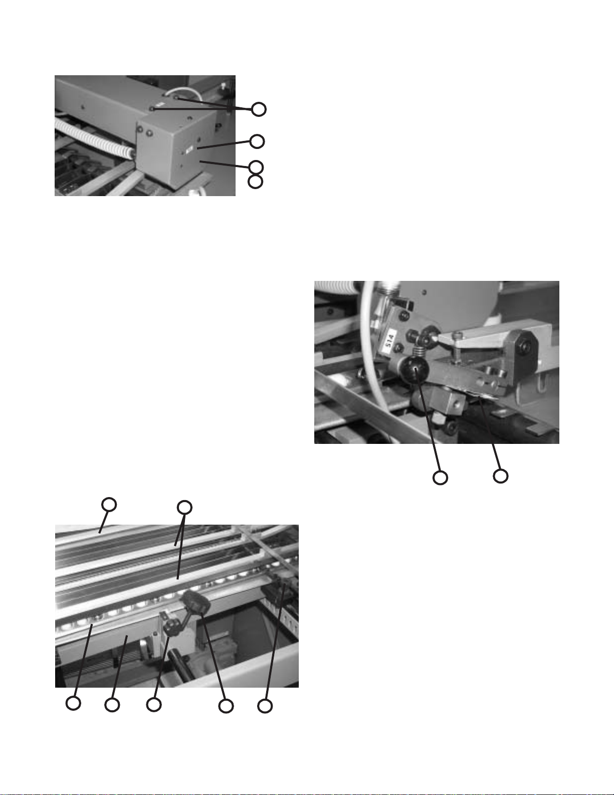
4
3
1
2
Figure 18
REGISTER OPERATION
Use the fluted knob (Figure 19-1) to slide the side guide
(19-2) with the marble holder (19-3) to the required location
1/16" away from the pile stack.
Move the sheet support (19-4) to the right hand side of
the sheet.
Place the steel and/or plastic marbles into the marble
holder (19-3). It is recommended to have at least two steel
marbles in the first four to six positions closest to the pile
feeder end.
The succeeding positions can be filled with steel or
plastic marbles depending on the stiffness of the paper. For
registering oblong sheets it is recommended to have at least
50% steel and 50% plastic marbles alternating in the marble
holder.
Clip-on sheet hold-downs (19-5) placed across the
register table prevent the sheets from rising. The hold-down
with the angle-formed end is to be placed in front of the
vacuum wheel.
The fluted knob (19-6) provides microadjust-ment of the
side guide (19-2). Knurled knobs (19-7) provide bias adjustment for the side guide for adjusting sheets that are not
square or for other unusual conditions.
The double sheet control (Figure 20) is adjusted to the
thickness of the paper being fed by pulling up the lever (20-
1) and inserting two paper strips (20-2) of the sheets to be
folded in the clip at the back of the lever.
The feeler segment remains inoperative when a single
sheet is passing through. When double sheets are being fed
through, the feeler segment is pulled against a microswitch
and the double sheet is stopped. Sheet feeding is stopped
and the message "2 sheet" appears on the counter readout.
The message remains until the double sheet is removed.
Raise the lever (20-1) to remove the double sheet.
1
2
4
5
Figure 20
1.0 DOUBLE SHEET DETECTOR
The double sheet detector consists of a scanner element,
microswitch and a free-wheel roller.
If the setting for paper thickness is exceeded, the
scanner element trips the microswitch, closing the magnetic
valve for the suction cycle so that sheet transfer is stopped
instantaneously. While the double sheet is stopped, the
sheets that are in the machine continue to be folded.
The double sheet stop must be set so that the scanner
probe remains untouched when a single sheet of paper
passes through. When two or more sheets are detected, it
3
2
6
Figure 19
1
7
must trigger the stop mechanism. (See Figure 21)
PAGE 39 TP10243-5
Page 40

A double sheet strikes the scanner on the microswitch,
interrupting the sheet flow-through.
With single sheet thickness, the scanner remains untouched and sheets move freely.
BAUMSET ADJUSTMENT
Figure 21
1.0 Adjustment of Folding Rollers
Folding accuracy is determined largely by precise adjustment of the folding rollers.
Using the Baumset precision adjustment device, the correct setting of the rollers can be made simply by inserting the
appropriate paper thickness between the adjustment plates. (See Figure 22)
With multiple thicknesses, insert single strips of the paper being folded equal to the number of sheets passing through
that roller combination..
Since the adjustment spindle acts directly on the folding rollers, clearance settings are exact.
Another method for setting the folding rollers is to insert paper strips between them by touch, the pressure adjustment
being made by turning the knurled screw.
The numbers on the Baumset adjustment knobs correspond to the buckle-plate numbers into which the sheet is fed. All
upper buckle plates have odd numbers while the plates below are even.
The Baumset adjustment device is correctly zeroed at the factory. If any adjustment is necessary, strips of single paper
thickness should be placed under every adjustment plate. The folding rollers are then reset by drawing strips of uniform
thickness through the appropriate pair of rollers as far as possible to the other side.
At the same time, the knurled screws are adjusted so that the strips can be withdrawn when medium drag is felt. When
this operation is complete, the dial rings are reset to zero.
Figure 22
TP10243-5 PAGE 40
Page 41
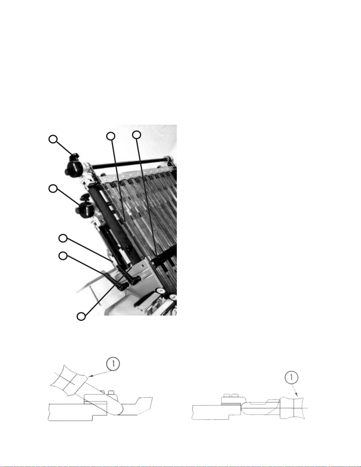
SETTING OF FOLD PLATES
NOTE:
Check the symbols on the fold plate stop (Figure 23-1) for
installation of the fold plate swing deflectors (Figure 24-1)
to avoid damaging the fold rollers. The deflector must only
be brought forward when the stop (23-1) with the deflector
symbol is in the forward position.
6
7
5
4
Be sure that the adjustment screw (23-2) is in contact with
the support rail on both sides.
Clamp the fold plates with the clamping screw (Figure
23-3).
The sheet-stop (23-4) should be moved to the desired
fold length according to the scale (23-5) by loosening the
clamping screw (23-6) and then turning the adjustment
wheel (23-7).
The sheet stop can be set at an angle for sheets that are
not cut square by loosening the clamping screw (23-6) and
turning the front adjustment wheel. The clamping screw
(23-3) must be tightened for this adjustment.
For the fitting of a fold plate, both sides of the stop (23-
1) must have the fold plate symbol turned to the front so
that the adjustment screw contacts the support rail.
Equal adjustments at both ends are needed to prevent
oblique folds or perforations.
CAUTION:
If the buckle space is reduced, be sure that the fold plate
does not rub against the folding rollers. If this occurs, the
rollers will be damaged. Check for rubbing by turning the
handwheel on the folder before turning the power on.
1
SETTING OF SHEET DEFLECTORS
3
2
Figure 23
Fold plates that are not required for folding can be closed
off with swing deflectors fitted in the infeed. The fold plate
is slightly withdrawn and the deflector (Figure 25-1) is
swung down and pushed in until it engages.
CAUTION:
Move stop (Figure 26-1) on both sides to avoid damage
to the folding rollers. Loosen the knurled screw (26-2).
Turn the stop and retighten the knurled screws. The
deflector symbol (26-3) must be in forward position.
Figure 24
Figure 25
PAGE 41 TP10243-5
Page 42
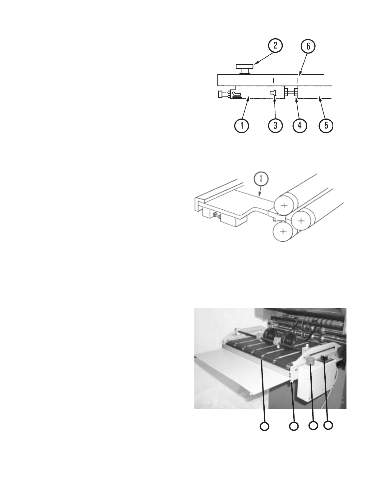
Check that the adjustment screws (26-4) are in contact with
the support rail (26-5) on both sides.
The basic position is marked by a notch (26-6) in the
fold-plate frame.
Setting S tationary Deflector
(Separate sheet deflector) (Figure 27-1)
The stationary sheet deflectors are installed and clamped
in place in the same way as the fold plates.
NOTE:
The fold plates in an 8-page folder will work in the #4 fold
plate position when four plates are desired. This applies to
folders equipped with three fold plates and one stationery
deflector.
STACKER (DELIVERY)
The motorized hang-on stacker has the following unique
features.
Figure 26
• Independent speed adjustment by using the speed
selector (Figure 28-1).
• Telescoping delivery tray that is fixed in position using
thumbscrews (28-2) below the tray.
• Nosebar with brush (28-3) that prevents sheets from
becoming trapped and eliminating a pinch point.
• The stacker can be mounted level or at an angle to assist
stacking of sheets that tend to spring open.
The stacker electrical power source is provided by
inserting the male receptacle on the stacker power cord into
the mating connector found on the left hand side on the
main electrical enclosure of the pile feeder.
Figure 27
TP10243-5 PAGE 42
3 2
Figure 28
1
4
Page 43
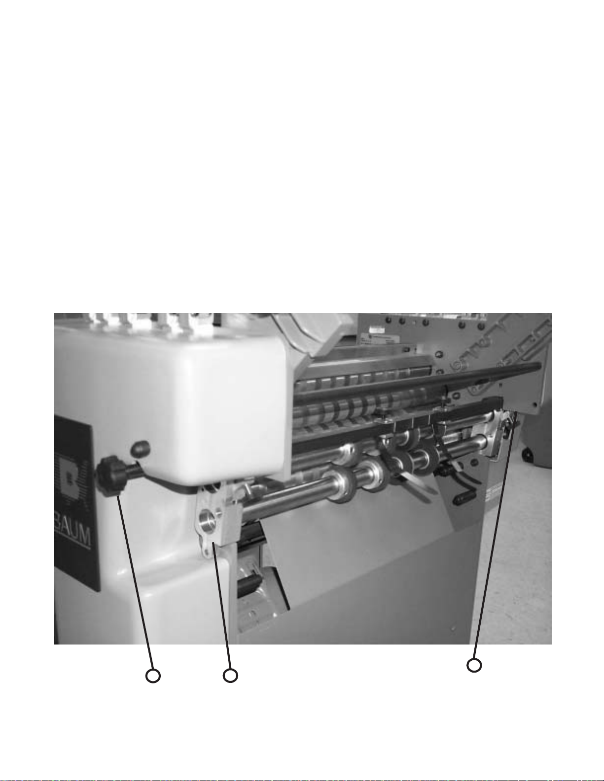
SCORING/SLITTING/PERFING
Your new folder is capable of many different applications that compliment the folding performance and provide for
greater productivity.
The folder is equipped with slitter shafts that are quickly set up for the required operation. These shafts accommodate
the mounting of the standard and optional accessories available that perform scoring, slitting and perforating functions.
1.0 Slitter Shaft Accessories Removal
To remove slitter shafts, carefully remove both knobs while supporting shafts by hand to prevent slitter assembly from
pivoting outward. (Figure 29-1). Once knobs have been removed, pivot slitter assembly outward away from machine. Add
or remove the parts needed for the current job using the wrench provided with the machine. See the following pages for
more information on perfing, scoring, and slitting. Reinstall slitter housing and knobs before starting the machine.
1
1
2
Figure 29
PAGE 43 TP10243-5
Page 44

1.1 Scoring
The folder can be used to score a sheet and deliver it flat, or to score a sheet after a fold or folds
have been made.
To ensure accuracy in making right angle folds, always score the sheet where the fold or folds are to
be made. This applies in all instances when a perforator cannot be used.
Various weights of stock with few or numerous folds require a different type of score. Some jobs
require a narrow, sharp score, usually when the folds are few, and a fuller, more rounded score when the
job becomes bulky.
The scoring blade is normally mounted on the upper slitter shaft. Scoring is accomplished by
running the score blade in one of the two grooves of the lower score collar. The sharpness and depth
of score is controlled by which groove the score is made in. The wider groove produces a wider, more
rounded score; while the narrower groove produces a sharper, tighter score. Also adjust scoring depth
using the micrometer adjustment knobs at each end of the slittershafts. The milled notch at the center
of the aluminum block is the nominal center adjustment.
You will find (3) yellow scribe lines on the tie bar at the exit of the first folder station. The yellow
line in the center is the approximate center of the folder and the sheet. The (2) outside yellow lines are
the approximate locations to position the scoring blsdes for a standard 11" x 17" sheet folded down to
a #10 letterfold.
The pullout tires should be close to the scores and at the edges of the sheet.
TP10243-5 PAGE 44
Page 45

1.2 Perforating
The folder may be used for perforating either the heads of booklets (to allow the air to escape in making right-angle folds)
or to slot perforate sheets delivered flat, using blades and strippers best adapted for a particular job.
All perforating blades are mounted on the upper shaft and run a side of the steel collar on the lower shaft with the flat side
of the blade just touching the anvil. When doing book work, perforator blades should be mounted with the bevel side of the
blade toward the following bank of fold rollers, the direction the signature will be travelling. (See Figure 31). When mounted in
this manner there is slightly less tendency for the sections of the signature to come apart and less tendency for one section to
pull out of line with another. This is particularly true when folding in an up fold plate.
A stripper must be used with each perforation. The forked spring steel stripper requires a little more care in mounting and is
most often used when perforating only, as there is less tendency for the perforated sheet to break apart.
PAGE 45 TP10243-5
Page 46

1.3 Slitting (Cutting) Sheets
Folders may be used to cut folded or flat sheets apart. Two or more cuts may be made if duplicate sets of slitters are
used.
Be careful when mounting slitter blades to collars in order to avoid ragged edges which can be caused by two
conditions:
1) Nicks or burrs on the collars or blades. Remove carefully by filing or using a fine piece of emery cloth.
2) Incorrect mounting of blades. Too much gap between slitting blades will result in a ragged cut
Space the pull out tires evenly to support the sheet.
Slitting
Note: Grooves in
lower scoring
collar are NOT
used for slitting
or perforating
Slitting Blade is located
tight against the sharp, flat
side of the anvil.
TP10243-5 PAGE 46
Page 47
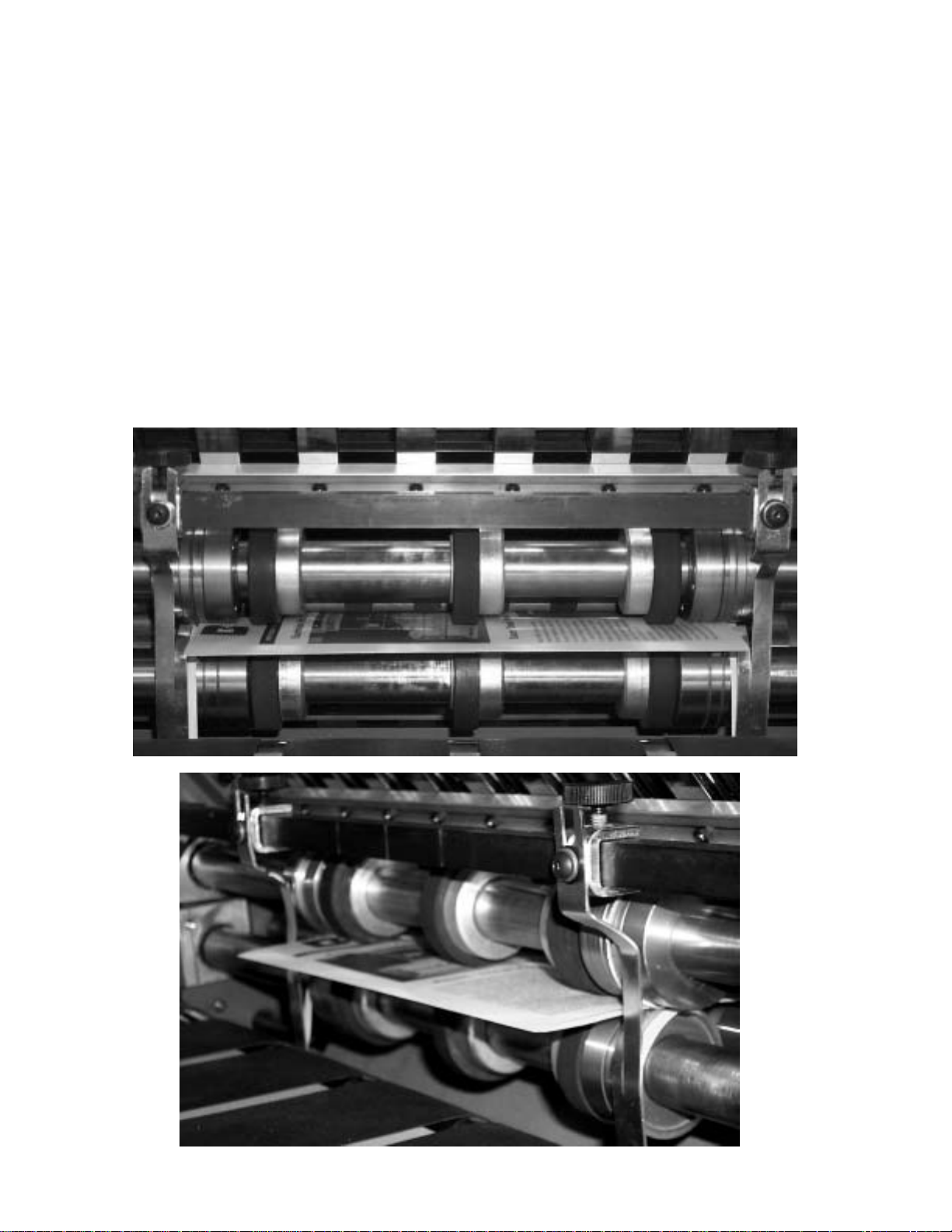
1.4 Trimming Edges of Booklets
Figure 30 shows the setup of cutting blades and strippers for trimming edges of booklets or outer edges of circulars
running two or more up.
Cutting blades are attached to blade holder collars so that the bevel of blades on the upper shaft are directed toward
the strip being trimmed and the bevel of blades on the lower shaft are directed away from the strip. Blades mounted in this
manner tend to turn trimmed edges down which helps guide them to the floor. Blade holder collars are turned out to allow
a set of pull-out tires to be placed close to the cutting blades, preventing the sheet from buckling or twisting at the point
where the cut is being made.
Use as many additional pull-out tires in the center of the sheet as necessary.
Set the collar, with blade attached, in the proper position on the upper shaft. Then move the collar/blade on the lower
shaft so that the flat sides of both blades press snugly together. Too much space between the blades will cause a ragged
edge on the finished booklet.
Do not attempt to trim less than one-eighth of an inch. On bulky or heavy sheets a wider trim is necessary.
Figure 30 shows the type strippers used for this work, mounted on the square bar directly above the shafts. Note that
one is right, the other left, placed accordingly. It may be necessary to bend the strippers slightly to avoid rubbing on the
cross carrier or stacker. Strippers are adjustable for up and down movement.
Figure 30
PAGE 47 TP10243-5
Page 48

1.5 Trimming a Strip from Center of Sheet
Figure 31 shows the setup for taking a quarter inch trim out of the center of a sheet. Two or more trims may be made
as long as duplicate sets of cutters and strippers are used and this setup adhered to.
A strip three sixteenths of an inch wide is the minimum trim. This is the thickness of two of the cutting blades placed
together and attached to a blade holder collar. Blades on the upper shaft, for all trims up to one-quarter inch, are
attached to one collar. If a strip wider than one-quarter of an inch is to be cut, each blade is attached to an individual
collar and any desired width may be cut.
To remove the trim, place the appropriate center stripper between two of the cutting blades, attached to a collar, as
shown in Figure 31.
Attaching blades to collars is very important and should be done with care. The bevel of the cutting blades on the
top shaft should always be directed toward the strip to be trimmed. The bevel of the blades on the lower shaft should
be directed away from the strip.
Before the cutting blades are tightened to the blade holder collars, slide both the collar and attached blade on the
end of the shaft so that they are accurately aligned. Place cutting blades on the upper shaft to the proper position
where the cut is to be made. Then place collars on the lower shaft so that the flat sides of the blades are pressed
snugly together. Too much space between the blades will give a ragged edge. Always examine blades for dullness and
nicks which will cause the same condition.
When blades are in the proper position, mount the stripper as shown. Be sure the stripper does not touch the sides
of the cutting blades.
With this setup, the trimmed out section automatically goes between the blades on the lower shaft, where it is
carried down and around and guided to the floor by the stripper wire.
1.6 Blade Installation
WARNING!!!
EXTREME CARE MUST BE TAKEN IN THE REMOVAL AND INSTALLATION OF ALL
SLITTER, PERFORATING, AND SCORING BLADES. EXCESSIVE FORCE AND/OR MISUSE CAN CAUSE
PERSONAL INJURY, BREAKAGE, EQUIPMENT AND MACHINE DAMAGE
All blade attachment is performed in the same manner. The locking collar of the blade holder is removed using the
provided spanner wrench.
The blade to be changed is moved far enough along the slitter shaft to permit the blade to be twisted open and
slipped from the shaft via the slit in the blade.
Install the new blade in the reverse order. Twist the blade so that the slit opens. Slip the blade onto the slitter
shaft, replace and tighten the locking collar with the furnished spanner wrench.
TP10243-5 PAGE 48
Page 49

Center Trimming
e
Center stripper wire
Spacers for
setting width
of strip
Slitting Blades are
located tight against th
sharp, flat side of the
anvil.
Note: Grooves in
lower scoring
collar are NOT
used for slitting or
perforating
Center trim
stripping collar.
Rotates loose on
lower slittershaft
trapped between the
anvils
. Lay wire
in center groove and twist ends
together at the bot t om. Wire
floats free and attracts center
waste and directs it to the floor
Figure 31
PAGE 49 TP10243-5
Page 50

LUBRICATION/MAINTENANCE
Pile Feeder
Vacuum Solenoid Valve The vacuum at the suction wheel is controlled by a
solenoid valve (Figure 32). This can be quickly and easily
removed to clean the piston by loosening the clamping
Figure 32
Gear Reducer Check fluid level annually. Check for wear. Refer
O-Rings (on vacuum wheel) See Figure 18.
Vacuum Pump Loss of vacuum and blow can be caused by clogged filters.
Register
Flat Belt Drive Shaft (hex shape) Check for wear periodically. Lubricate with Baum
Support Bars Lubricate the three support bars on which the register
springs. Be careful not to damage the piston and cylinder.
See Figure 17.
to parts manual for part number.
Check periodically. Check vanes for wear after 15,000
hours of service. Refer to parts manual for ordering parts.
Lubricant "W". Lithium base grease or equivalent
periodically.
guide slides periodically using Lithius base grease.
Folder
Handwheel Lubricate bi-annually with commercial grade
lubricating oil.
Fold Rolls WARNING: Never clean fold rolls while the machine is
running.
With the folder turned off, rub down the fold rolls with a
cloth dampened with "Surewash". Never immerse fold
rolls into the washing solvent. After cleaning, they should
be rubbed down with a clean dry cloth.
Gear Drive The helical gear drive is lubricated by an automatic
grease dispenser located inside the LH guard. Use
the label on the LH guard to record lubrication change
date [It should be changed every 9 months]. To activate
the dispenser, screw the eye bolt (Figure 33-1) into the lid
(33-2) of the dispenser until ring (33-3) comes off. Shake
the cannister when installing to insure that it rattles,
signifying that it has been activated. See parts manual for
replacement dispensers.
Figure 33
WARNING: Never open grease dispenser. Even when
empty, container remains under pressure. If damaged,
caustic liquid may leak out. If contact is made with skin,
flush repeatedly with water.
Pullout Tires Check periodically for wear, uneven tires can cause the
sheet to twist.
TP10243-5 PAGE 50
Page 51

TECHNICAL SPECIFICATIONS
BAUM 2020
Maximum sheet size 20.5" x 31" [52 x 78.7cm]
Minimum sheet size 4" x 6" [10.1 x 15.2cm]
Maximum folder speed 8200 ipm [208m/min]
Maximum pile height 25" [63.5cm]
Minimum fold length 1.57" [40mm]
Maximum fold length 20.5" [52cm] (parallel folder)
Slitter shaft diameter 1 1/8" [28.6mm]
Electrical 220 Volt, 1 phase, 60 Hz, 34 Amperes
220 Volt, 3 phase, 60 Hz, 21 Amperes
See serial plate on folder
ACCESSORIES
In addition to the various folding, slitting, perforating and
scoring functions the Baum 2020 can perform even more
productive functions using the following accessories and
more.
• Jam Detectors
• Remote Control
• Static Eliminator
• Sound Guards
• Gluing Fold Plates
• Gatefold Plate
Contact your local Baumfolder Corporation sales representative for further information.
PAGE 51 TP10243-5
Page 52

TROUBLESHOOTING
PROBLEM CAUSE REMEDY
Sheets stick together Inadequate ink drying, cut Fan out thoroughly when
particularly along sides. with blunt guillotine blade. piling, increase blower air.
Suction wheels picks Excessive suction. Reduce vacuum setting.
up double sheets. Air blow improperly set Increase air blow
Sheets stick together
Double sheet stop Set only to single paper Correct to double paper
reacts to single sheets. thickness. thickness. Tighten lock nut.
Sheet twists after suction Side Guide on register Bring guide plate forward.
wheel finishes feed-in. set too far back.
Too few marbles at start of Increase number of marbles
side gage. if necessary.
Suction gap too short. Increase gap setting.
Sheet leading edge If the leading edge of the sheet Adjust holder tongue
buckles on register or is being buckled, the holder accordingly.
lower sheets are being tongue below the suction wheel
pushed forward. is too high; if too low, sheets
are pushed forward.
Dirty valve piston sticking. Clean.
Sheets fails to run into the Only at 1st buckle plate: Fit sheet deflector to 1st
buckle plate. A curl in the sheet buckle and fold in 3rd
can cause the leading- buckle plate.
edge to bend up or down
thus missing the upper or
lower buckle throat.
On all buckle plates: sheet Advance lower buckle plate
missing the buckle plate lips accordingly.
underlips.
Sheets fails to re-emerge Sheet unable to buckle as Set lower buckle plate
from buckle plate. buckle space too small. lip further back.
Folding rollers blunt or Wash off rollers with the
clogged with ink. type of rubberised-cloth
cleaning agent used in
offset work.
Inadequate inside clearance Increase clearance as
in buckle plate. necessary.
TP10243-5 PAGE 52
Page 53

TROUBLESHOOTING - continued
PROBLEM CAUSE REMEDY
Sheets fails to re-emerge Product too thick for folding. Consult Baum technical rep.
from buckle plate.
Not enough roll pressures. Check Baumset settings.
Sheet remains lying on Electrostatic charge in Fit discharge unit at the
the roller table of the 2nd product caused by friction exit to the 1st station
station or fails to run into with rollers and deflectors or arrange for appropriate
the 1st buckle plate of the and also relatively low humidity on the premises.
2nd folding station. humidity.
Damping rods and sheet holder Raise as necessary.
set too low.
Wrinkling after the 1st Register guide not at right- Set angle correctly.
fold, either across or angles to the folding rollers.
parallel.
Sheet drawn too sharply against Insert fewer balls or use
the register guide causing a wave lighter ones.
to form.
Buckle plate feed stop not Correct buckle plate stop
parallel to the incoming sheet setting.
edge.
Folding rollers set too tight. Slacken roller setting.
Crooked perforation after Register guide and buckle Reset.
1st fold. plate stop not at right angles
to each other.
Faulty setting of folding Check and reset as
rollers and slitter shaft. necessary.
Lower buckle plate lip Set to zero position.
crooked.
Sheet corners buckled Sheet deflector set too low. If the corners are buckled
up or down after the upwards, set the upper
1st fold. sheet deflectors back
evenly; if the corners are
buckled downwards, the
lower deflectors must
similarly be set back
evenly by underlaying
pieces of card. In no
circumstances alter the
basic setting of the
deflectors.
PAGE 53 TP10243-5
Page 54

OPERATING TIPS
Setup
When setting up a job on your folder, watch so the sheet
doesn't end up with either the RH or LH edge along the edge
of a fold pan or register plate. This could kick it over
causing inaccurate folding.
Brass Tipped Screws
When replacing screws in collars and various other
assemblies, be sure to note if they are brass tipped screws.
Using non-brass screws as replacements will cause scarring
of the shaft, making collars difficult to move.
Static Electricity
If you do not have an electrical static eliminator, here are
some ideas to help reduce static electricity:
• Make sure the machine frame is grounded.
• Try using static tinsel across the register table and
feeder.
• Locate the folder out of direct drafts such as doorways
and air vents.
• Cover jobs with plastic between the press and the folder
if much time will elapse before the job is to be run.
Cutting Blade Wear
To help extend the life of all cutting blades, check for
possible burrs on the mounting collar. Lay a sheet of emery
cloth on a flat surface and rub the collar around a few times
to remove any burrs. The blade will now rest flat against
the collar, giving a more even rotation.
Measuring Odd Thirds
When measuring odd thirds as needed for a Z-fold for
example, on an 11 inch sheet, lay your ruler on a diagonal
of 12 inches instead. Mark at four and eight inches, and
you will now be able to easily measure 1/3 of the sheet.
Pull-out Bands
Periodically check for wear on the rubber pull-out bands
on each slitter shaft. When each sheet passes through the
last rolls, there is another 1 3/4 inches left on the sheet
before it is completely out of the folder. At this point, the
only thing controlling the sheet is the pull out bands. If
they are worn or uneven, the sheet can twist after dropping
out of the rolls when travelling that last 1 3/4 inches. Be
sure when replacing these worn pull-out bands that you
replace the complete set, so you will always have an even
pull on both sides.
Slitter Shaft Setup
Here is an easy way to set up your slitter shaft accessories. Mark up a dummy sheet with the scores, perforations,
etc. locations. Roll through by hand and position your
slitter shaft accessories accordingly. Also, keep all set
screws for the slitter shaft accessories facing out, so you
don't have to turn the shafts to get to the screws.
TIPS FOR FOLDING
The following section contains a number of hints drawn
from practical experience for the setting up and adjustment
of folding machines.
Roller Setting for Accordian and Letter Folding
The rollers used for these types of folds must be set only
to single paper thickness. The folding rollers following the
final fold must, however, be set once more to the total
thickness of the paper passing through.
Processing Thin Printing Stock
It is essential that the folding rollers be adjusted with
maximum precision.
Lightweight printed stock is more easily folded when the
paper is slightly moist as this imparts a greater degree of
stiffness. For sheet transportation on the register table and
at the right-angle folds, as few marbles as possible should be
used and these should be of light weight.
When lightweight printed stock is being folded, the
folding machine should be started up as slowly as possible.
Only after the necessary precision adjustments have been
made should the machine speed be increased in accordance
with the paper. It is essential to ensure that the speed is
increased only to a point where quality is maintained.
Folding Roller Adjustment
Contrary to popular opinion, paper strips trimmed for
this purpose should not be inserted between the clamp
blocks of the Baumset. The strips should be folded according to the required pattern and inserted with the folds.
Paper Grain in Letter Folds
With paper of up to 90 g/m, the three-directional letter
fold can be produced even if the grain is at right angles to
the fold. From 90 g/m upwards, better folds are produced if
the paper grain runs parallel to the fold.
Using Guide Marbles
The basic rule is that as few marbles should be used as
possible. Steel marbles should be used only when necessary
for the type of paper and the required fold. Conveyor tapes
last longer if unnecessary marbles are removed.
If stream delivery on parallel folding work is not
uniform, try using more marbles after the parallel folding
station.
A simple rule of thumb is that the thicker the folded
sheet becomes from station to station, the greater the load
exerted by the balls should be to facilitate sheet movement.
TP10243-5 PAGE 54
Page 55
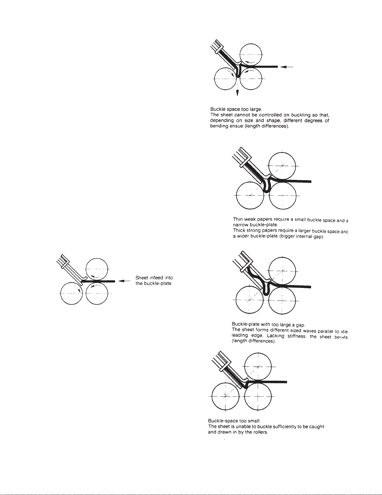
Fixing Crooked Perforations
If misaligned perforations appear after the parallel
folding station, first check for correct squareness setting of
the register guide relative to the buckle plate stop. If square,
the sheet deflector following the last buckle plate must be
set back slightly on the side on which the sheet is tending to
advance.
Adjustment can be made by inserting a card underlay of
suitable thickness. The affected sheet side then has to travel
a greater distance, so a perfect perforation can be made
without changing the fold position
.
Bottom Plate Lip Adjustment
Since paper qualities and thicknesses vary greatly, it is
essential that buckle plates are properly adjusted.
With thin papers, the lower buckle lip is brought slightly
forward. With thicker paper it must be set further back. The
buckle plate configuration is directly related to the thickness
and stiffness of the paper being folded. This relationship
must be taken into account if a high quality fold is to be
achieved.
The adjustments can be made by setting the nuts on the
top edge of the buckle plate to give the necessary reading
against a scale on the side buckle plate post. A pointer
marks the normal setting of the buckle plate. The inside
width between the buckle plate section rods can also be
varied without altering the setting of the buckle throat.
Figure 35
Figure 36
Figure 34
Figure 37
Figure 38
PAGE 55 TP10243-5
Page 56

Principles of Mechanical Folding
The buckle folding principle
In buckle folding, each station consists of three rollers
and a buckle plate. The first two rollers are arranged one
vertically above the other and they carry the incoming sheet
into the buckle plate until it reaches a feed guide stop that
can be adjusted as required.
The sheet is delivered into the buckle plate at a determined speed. The leading edge strikes the paper stop. Once
against the stop the sheet continues to be driven. A buckle
forms in the space between the three rollers. As this sags
downward, it is picked up by the rotating rollers and the
fold is formed as the sheet passes through them.
It can be seen that in this case the folding process is not
restricted to any cyclical movement and is thus capable of a
very high output.
For each folding station it is possible to fit up to four
buckle plates, arranged alternately above and below. Buckle
plates that are not required for a particular folding operation
can be replaced by sheet deflectors, allowing one or more
buckle plates in a folding station to be by-passed. It is thus
possible to execute a large number of fold variations.
The gap between the rollers must be set to the thickness
of the paper that is passing through. Certain deviations
must be made for special types of parallel folding.
Figure 41
Figure 42
Figure 39
Figure 40
TP10243-5 PAGE 56
Figure 43
Figure 44
Page 57

JOB SETUP EXAMPLE
This sheet is only a guide to setup and operation
of the Baum 2015/2018/2020 Pile feed folders.
Jobs will vary and procedures will need to be
modified.
1. Hand fold a sample as close as possible of the job to
be run. Mark the sample so that it is not lost during
setup. Measure the overall length and width of the sheet
if you do not already know them, using the scale located
on the holddown in the center of the register table.
2. Start with the feeder and move in progression to the
exit end of the last fold section to complete the setup of
the folder. There is no need to turn the power on until the
setup is complete.
3. Set the sideguide on the pile feeder to half of the width
of the sheet width using the scale on the frame. Remove
the LH sideguide for easy access to load paper. See Fig.
45.
4. Set the double front blow bar to the proper air settings referring to the chart on the side of the control
cabinet. See Figures 46 and 47.
5. Set the double sheet detector using (2) thicknesses of
the stock being fed and insert into the lever and clip.
6. Load paper onto the pile feed platform. Be sure to fan
the paper before loading to add air in between the sheets
for easier feeding. Also note that the loading of the paper
must be positioned to correspond to the folding imposition that you want to achieve in the folding unit(s). You
must determine if you want the paper face up, or face
down, or head first, or tail first. Refer to your hand folded
sample to determine which foldplates you will be using
and the loading of the paper.
7. Install LH see-thru sideguide and position register
guide approximately 1/16 to 1/8” away from LH side of
paper on pile feeder to insure that paper can slide freely
during feeding. See figure 48.
8. Install the small metal clip that fastens to the end of
the register guide to keep an up-curl from riding over the
end of the register guide.
Check register marble configurationCheck register marble configuration
Check register marble configuration to make
Check register marble configurationCheck register marble configuration
sure that it matches the job that you are running.
At least (1) to (2) steel marbles are recommended
at the end of the register closest to the pile feeder
and (2) more at the end closest to the fold rollers.
The marble configuration in between depends
upon the weight of stock and whether the feeding
is landscape or portrait. To
Fig 45
Fig 46
Fig 47
Fig 48
PAGE 57 TP10243-5
Page 58
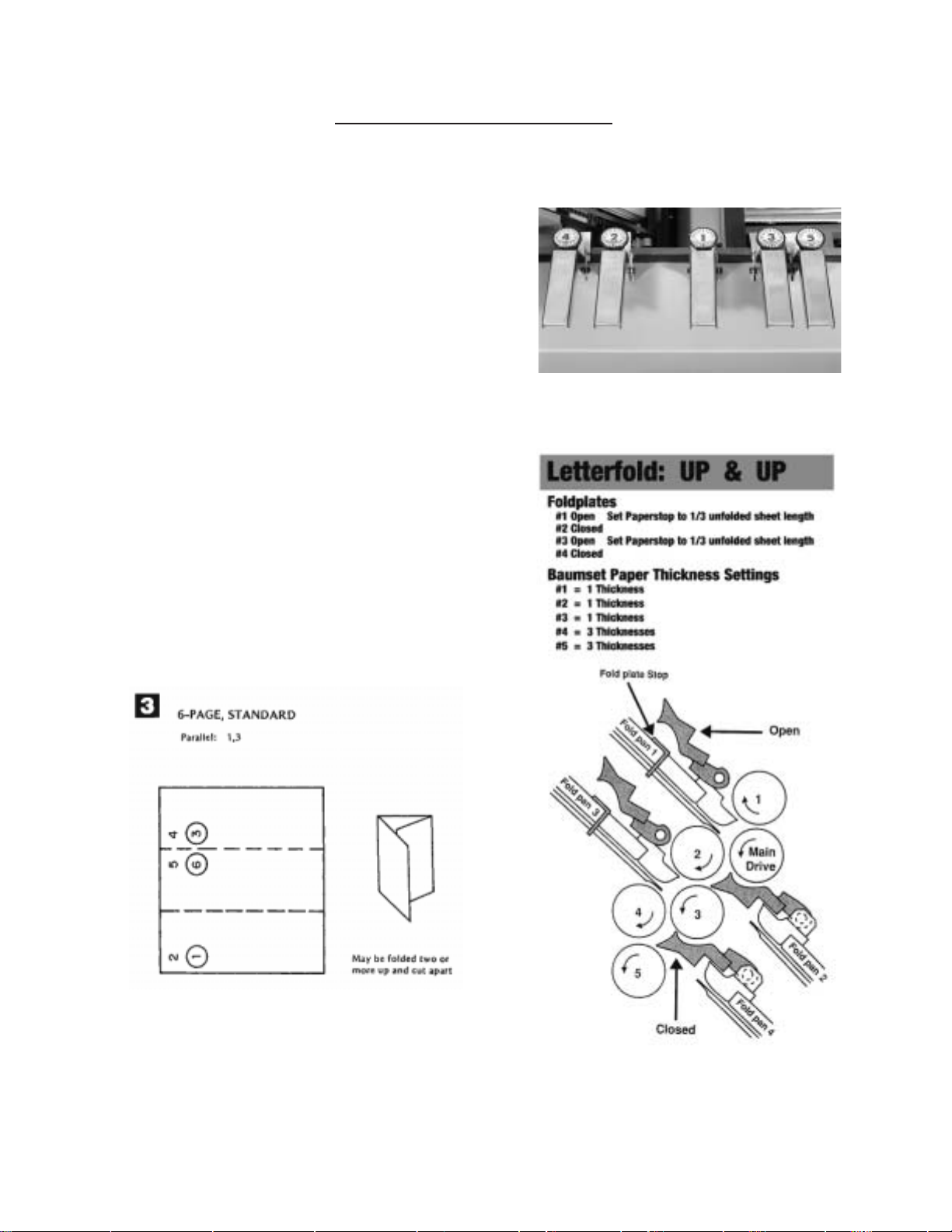
JOB SETUP EXAMPLE
many steel marbles can drive the sheet too hard
and causing feeding problems.
1. Place register holddowns in proper locations for
the sheet width being fed. Note that for 11x17 sheets
being fed in the 11 inch width, place a register
holddown between the LH see-thru guide and the
vacuum wheel to keep air from cupping the sheet and
causing stumbling. Note that the register holddown
with the scale is always located in the center of the
register in front of the vacuum. Be careful when
placing the holddown on the right hand edge of the
sheet to angle the holddown slightly to prevent the
right hand edge from curling up inside and stumbling.
2. Set the Baumsets by inserting strips of paper of the
job that is being run. Only insert the thickness that
corresponds to the tailing or minimum thickness that
the roller must drive without loosing control of the
paper. You need to refer to your hand-folded sample to
follow the paper path See fig 49. Refer also to the
example fold given in Fig. 50 that shows a cut-away
section of the folder and notes the proper foldplate and
Baumset settings for the imposition shown.
Fig. 49
Fig. 50
TP10243-5 PAGE 58
Page 59

JOB SETUP EXAMPLE
1. Set the foldplates to the proper open and closed
positions by rotating the stop blocks and placing
the correct symbol for either open of closed to the
position closest to the fold rollers. Then set the
desired fold depths using the scale on the belt and
reading at the yellow mark on the indicator.
2. Setup the slittershafts using the proper perforating
scoring or slitting accessories. If just a parallel
folder is being used an perforating, scoring or slitting
is not required, pullout tires must still remain on the
slittershafts to properly eject the sheets. Note that a
good setup procedure is to have all the setscrews
facing outward at the same clock position. This
eliminates a lot of handwheel turning to get to the
setscrews during job changes. See Fig. 51
3. Setup Delivery Stacker Wheels to the expected
position of the paper as it ejects the folder. The
independent speed control will need to be set during
the initial fold operation to insure proper shingling.
Note that the exit holddown straps must also be
installed to kick the sheet down onto the delivery
stacker.
Fig. 51 Perforating on slittershaft
Right angle FoldingRight angle Folding
Right angle Folding
Right angle FoldingRight angle Folding
When adding an 8-page or 16-page folder to a parallel unit
it is highly recommended that the stock must be either
perforated or scored as it exits the previous fold unit. The
perforating or scoring is to be performed at the line of the fold
that is to be folded in the next fold section. This weakens
the grain of the stock so that a consistent, quality fold can
be achieved. Perforating is also needed to relieve air that
can become trapped in the folding process and create
wrinkles in the paper. The size of the perforator tooth can
make a difference in the amount of air that can escape and
remove the wrinkle problem. Failure to score or perforate a
sheet going into a right angle folder will result in inconsistent fold quality.
Refer to your operator’s manual for scoring, perforating
and slitting information.
Marbleholder Setup
Note that marble placement can be critical on some jobs
and not on others. You may want to remove some
marbles that are in the end that accepts the sheets at a
right angle so that the sheets do not bounce back when
trying to get under the marbles. At least (2) steel
marbles are recommended at the end closest to the fold
rollers to maintain sheet control against the guide.
Fig. 52 Scoring on slittershafts
PAGE 59 TP10243-5
Page 60

JOB SETUP EXAMPLE
TP10243-5 PAGE 60
Page 61
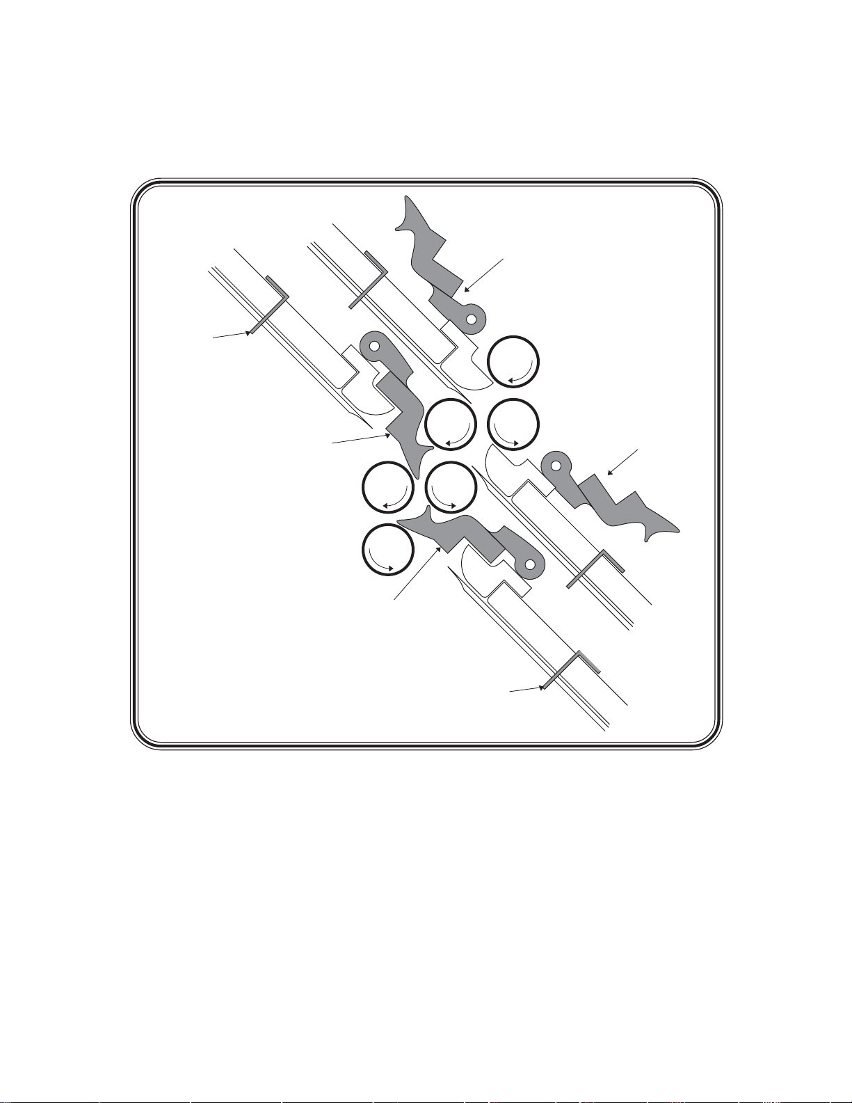
R
S
HEET
S
TOP
FOLD PAN #3
FOLD PAN #1
DEFLECTOR
OPEN
1
MAIN
DRIVE
DEFLECTO
OPEN
DEFLECTOR
CLOSED
2
34
5
FOLD PAN #2
DEFLECTOR
CLOSED
SHEET
STOP
FOLD PAN #4
IMPOSITIONS
18 MOST
POPULAR FOLDS
PAGE 61 TP10243-5
Page 62

On a buckle folder , the sheet is laid flat on a register table and then enters the fold pan assembly where it
R
S
S
comes to a stop against the stationary fold plate stop. A series of buckles then forms throughout the sheet. The
buckles whithin the fold pan are kept very small by the narrow channel design. The buckles at the end of the
fold pan, however, will be lar ger. The fold pans and fold rollers are configured such that the lar ge buckle will
always form downward, where it can be grabbed by the fold rollers and compressed into a fold.
Look at the figure below. You can see that fold pans #1 and #3 are angled upwards. Because of this
and the configuration of the fold rollers, sheets fed into the #1 and #3 fold pans will always be folded up
(i.e. so that the “up” surface of the sheet is folded into contact with itself).
Likewise, because foldpans #2 and #4 are angled down, sheets fed into them will be down-folds; the
“down” surface of the sheet will be folded into contact with itself.
HEET
TOP
FOLD PAN #1
FOLD PAN #3
DEFLECTOR
OPEN
1
MAIN
DRIVE
DEFLECTO
OPEN
DEFLECTOR
CLOSED
2
34
5
DEFLECTOR
CLOSED
FOLD PAN #2
Fold Pan Fold
#1 UP
#2 DOWN
#3 UP
#4 DOWN
TP10243-5 PAGE 62
SHEET
STOP
FOLD PAN #4
Page 63
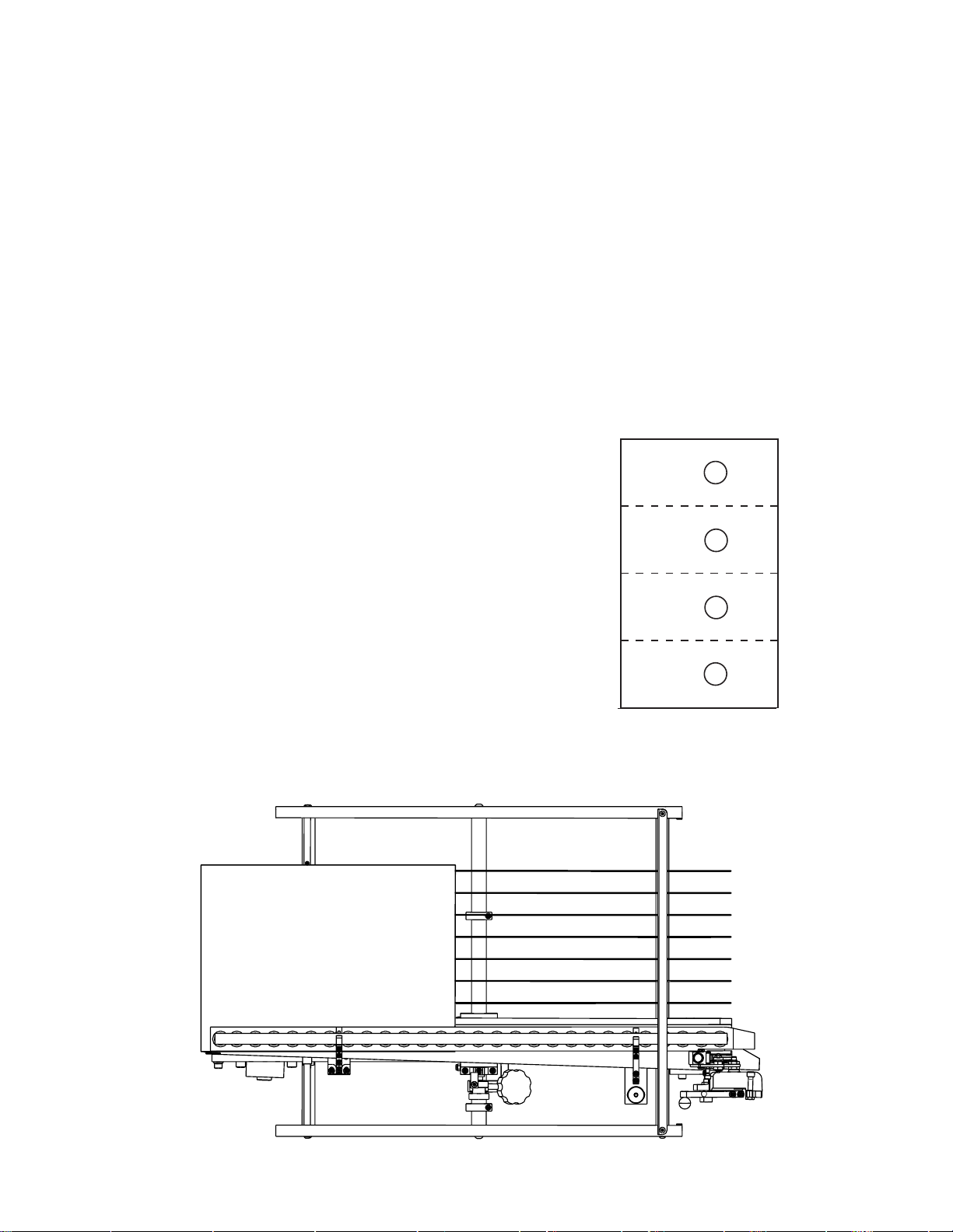
MANUAL USAGE
1
23
4
6
5
7
8
LEADING EDGE
S
I
D
E
G
U
I
D
E
Use this manual when you need to know how to set-up your folder to end up with a particular folded
piece or, if possible, when planning the layout before printing the job. In most cases, the page numbers
and their orientations after the fold are included. Below is an explanation of how to read the diagrams in
this manual. On the next page is a quick explanation of the basic theory of buckle folding. Although
reasonable care has been taken to assure accuracy , Baumfolder Corporation does not assume any responsibility for any errors that might inadvertently be contained in this manual. When trying a new fold, it is
always advisible to set up a test run to check for potential problems.
1. Refer to the diagram below . Visualize the sheet to be folded lying flat on the register table. The
edge toward the fold rolls is called the “LEADING EDGE”. The paper edge under the register guide
will be referred to as the “SIDE GUIDE”.
In this manual, each folding diagram has been
rotated clockwise 90 degrees from what is visualized
below so that they appear as pictured to the right.
The dotted lines represent the creases where the
paper has been folded.
L
E
A
D
I
N
G
E
D
G
E
SIDE
GUIDE
PAGE 63 TP10243-5
Page 64

TYPICAL LA YOUT AND
1
23
4
6
5
7
8
L
E
A
D
I
N
G
E
D
G
E
SIDE GUIDE
SHEET ORIENT ATION
Each numbered Imposition Block
in this manual contains:
A. Imposition Title
B. Fold Pans Used
C. Sheet Layout
D. Folded Sample
2. Dashed lines represent folds.
Page numbers or letters without circles are face up.
Page numbers or letters with circles are on the underside of the sheet.
When letters are used, folds are to be made “A” to “A”, “B” to “B”, etc.
3. In order to use your Imposition Manual properly, note that the pans in each folding section are
numbered conventionally as follows:
PARALLEL FOLDER 1st STATION (8 page)
#1 (UP) #1 (UP)
#2 (DOWN) #2 (DOWN)
#3 (UP) #3 (UP)
#4 (DOWN) #4 (DOWN)
2nd STATION (16 page) 3rd STATION (32 page)
#1 (UP) #1 (UP)
#2 (DOWN) #2 (DOWN)
#3 (UP)
#4 (DOWN)
NOTES
1. When planning an imposition, check your folded layout for proper page numbers and guide edges.
Verify that your folder is large enough to do the job, that is, that the fold pan depths are suf ficient
for the folds desired.
2. If the desired imposition is unusual, try the stock on the folder before printing (make a trial
folding run).
3. Use the most logical layout and avoid unnecessary problems such as air pockets and adverse
paper grain.
TP10243-5 PAGE 64
4. For better results, use scores whenever possible.
5. There are alternate ways of making many of these impositions; those presented herein are in
common use to achieve the results shown. An experienced operator will often develop alternate
methods to achieve the same results.
Page 65

4-P AGE
Parallel: 1
May be folded two or
1
more up and cut apart.
4-P AGE, DOUBLE
IMPOSITION
Parallel: 1, 2, 3
2
May be folded two or
more up and cut apart.
Trim edge after folding.
6-P AGE, STANDARD
Parallel: 1, 3
May be folded two or
3
more up and cut apart.
23
6-PAGE, ACCORDION
Parallel: 1, 2
May be folded two or
4
more up and cut apart.
4
1
5
3
4
1
2
4
1
23
8-PAGE, P ARALLEL
IMPOSITION
Parallel: 1, 2
May be folded two or
more up and cut apart.
4
5
6
1
23
8-P AGE, RIGHT ANGLE
Parallel: 1
8-Page: 1
6
2
1
3
4
6
5
4
4
5
6
8
7
1
23
PAGE 65 TP10243-5
3
2
1
5
6
7
8
Page 66
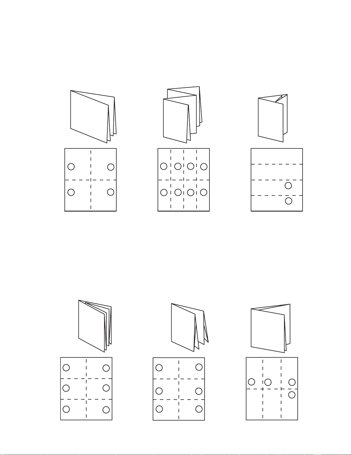
8-P AGE, TWO RIGHT
ANGLE OBLONG
Parallel: 1
7
8-Page: 1
8-P AGE, RIGHT
ANGLE DOUBLE
IMPOSITION
8
Parallel: 1
8-Page: 1, 2, 3
8-PAGE, P ARALLEL
OVER & OVER
Parallel: 1, 2, 4
9
May be run two or
more up and cut apart.
C
10
4
3
2
1
12-P AGE BOOK,
SADDLE STITCH
Parallel: 1, 2
8-Page: 2
5
6
7
8
11
4
3
2
1
12-P AGE BOOK,
SADDLE STITCH
Parallel: 1, 2
8-Page: 1
4
5
6
7
8
5
3
6
7
2
8
1
12-P AGE LETTER
FOLD, HEADS OUT
12
Parallel: 1
8-Page: 1, 2
B
A
C
B
A
8
9
10
9
12
11
TP10243-5 PAGE 66
5
6
3
4
1
2
6
5
2
1
4
3
11
12
7
8
C
B
9
10
B
C
Page 67

13
12-P AGE LETTER
FOLD, HEADS IN
Parallel: 1
8-Page: 1, 3
B
C
B
12-P AGE LETTER
FOLD, ACCORDION
14
C
Parallel: 1
8-Page: 1, 2
B
C
15
B
C
16-PAGE, THREE
RIGHT ANGLE BOOK
IMPOSITION
Parallel: 1 8-Page: 1
16-Page: 1 May be run
two or more up and cut
apart.
6
5
12
9
8
11
10
7
3
4
13
14
16
15
1
2
16
12-P AGE FOLDER,
HEADS OUT
Parallel: 1
8-Page: 1, 2
4
3
2
1
15
16
13
14
12
11
10
9
24-P AGE BOOKLET
Parallel: 1, 2
17
5
6
7
8
8-Page: 1, 2
2
1
4
3
6
5
23
24
19
20
21
22
14
13
18
17
16
15
11
12
18
6
5
9
10
7
8
2
1
32-P AGE BOOK
Parallel: 1, 2, 3
8-Page: 1, 2
8
7
27
28
4
3
31
32
25
26
29
30
22
18
17
21
24
23
20
19
9
10
11
12
13
14
15
16
PAGE 67 TP10243-5
Page 68

Baumfolder has authorized dealers located throughout the United States.
Call toll free, 1-800/543-6107 for parts or the
number of your nearest authorized dealer .
BAUMFOLDER
C O R P O R A T I O N
Quality Bindery Equipment Since 1917
1660 Campbell Road
Sidney, Ohio 45365-0728
Phone: 937/492-1281 or 800/543-6107
Fax: 800/452-0947
Internet: www.baumfolder.com
E-mail: baumfolder@baumfolder.com
TP10243-5 PAGE 68
 Loading...