

Page 1
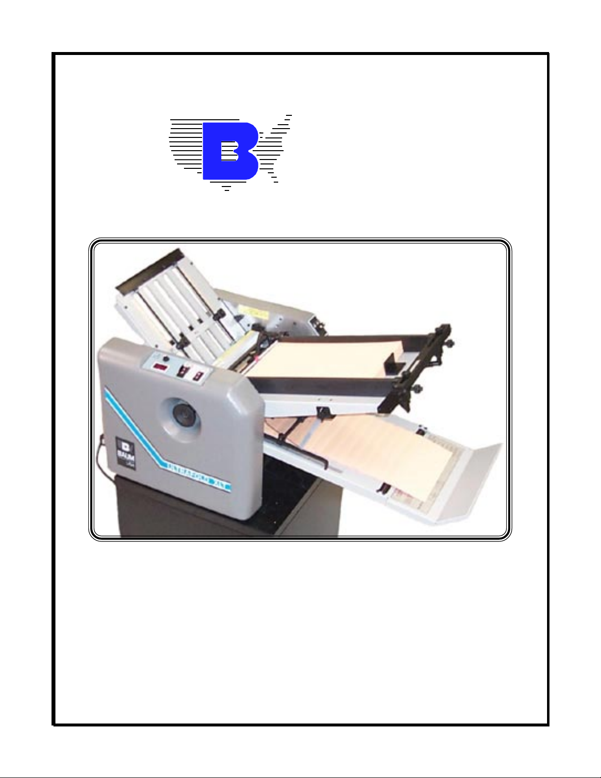
BAUMFOLDER
CORPORATION
Quality Bindery Equipment Since 1917
714XLT BATCH COUNTER
INSTALLATION & PARTS
MANUAL
©Baumfolder Corporation, 2000 Printed in U.S.A. TP10330
1 TP10330
Page 2

© 2000 Baumfolder Corporation
All Rights Reserved
WARNING
Do not operate this machine without all guarding in place.
Do not make adjustments or perform maintenance on this machine with power on.
Keep the machine and the work area clean and free of spills to prevent accidents.
Be sure to replace any safety decals that may have been detached for any reason.
Baumfolder reserves the right to make changes in design or to make additions or improvements in its
products without imposing any obligation upon itself to install them on its previously manufactured
products. It is recommended that modifications to this equipment not be made without the advice and
express written consent of Baumfolder Corporation.
FOLDER IDENTIFICATION
MODEL NO: _______________________________ SERIAL NO: _____________________________
SALES AGENCY: ____________________________________________________________________
INSTALLED BY: _____________________________________________ DATE: ________________
PHONE NO: ________________________________
TP10330 2
Page 3

Contents
FUNDAMENTAL SAFETY............................................................................................................... 4
INSTRUCTIONS ................................................................................................................................ 8
PARTS................................................................................................................................................ 12
3 TP10330
Page 4

FUNDAMENTAL SAFETY
INSTRUCTIONS!
The diagrams and descriptions used in these instructions are not necessarily
applicable to the specification of the machine supplied. Modifications, made
for reasons of technical or operational improvement, are embodied without
notice.
TP10330 4
Page 5

FUNDAMENTAL SAFETY
INSTRUCTIONS!
These operating instructions are designed to familiarize
the user with the machine and its designated use.
The instruction manual contains important information on
how to operate the machine safely, properly and
most efficiently. Observing these instructions helps to
avoid danger, to reduce repair costs and downtimes and
to increase the reliability and life of the machine.
In addition to the operating instructions and to the mandatory rules
and regulations for accident prevention and environmental
protection in the country and place of use of the machine, the
generally recognized technical rules for safe and proper working
must also be observed.
The following signs and designations are used in the
manual to designate instructions of particular importance.
1.0.3
The machine/installation is designed exclusively for paper finishing
of minimum and maximum sheet sizes (see corresponding operating
instructions). Using the machine/ installation for purposes other
than those mentioned above is considered contrary to its designated
use. The manufacturer/supplier cannot be held liable for any
damage or injury arising from such misuse. The risk of such misuse
lies entirely with the user.
Operating the machine within the limits of its designated
use also involves observing the instructions set out in the
operating manual and complying with the inspection and
maintenance directives. The working temperature of the
machine should range between 0° and 55° C.
1.1 Organizational measures
1.1.1
The operating instructions must always be at hand at the
place of use of the machine/plant, e.g. by stowing them in the tool
compartment or tool-box provided for such purpose.
Important
(refers to special information on how to use the
machine/plant most efficiently)
Attention
(refers to special information and/or orders and
prohibitions directed towards preventing
damage)
Danger
(refers to orders and prohibitions designed prevent injury or extensive damage)
1.0 Basic operation and designated use
of the machine/plant
1.0.1
The machine /plant has been built in accordance with
state-of-the art standards and the recognized safety rules.
Nevertheless, its use may constitute a risk to life and limb
of the user or of third parties, or cause damage to the
machine and to other material property.
1.1.2
Personnel entrusted with work on the machine must have
read the operating instructions and in particular the chapter on
safety before beginning work. Reading the instructions after work
has begun is too late. This applies especially to persons working
only occasionally on the machine, e.g. during setting up or
maintenance.
1.1.3
For reasons of security, long hair must be tied back or
otherwise secured, garments must be close-fitting and no
jewelry - such as rings - may be worn. Injury may result
from being caught up in the machinery or from rings
catching on moving parts.
1.1.4
Observe all safety instructions and warnings attached to
the machine/plant.
1.1.5
See to it that safety instructions and warnings attached to
the machine are always complete and perfectly legible.
1.1.6
In the event of safety-relevant modifications or changes in
the behaviour of the machine/plant during operation, stop
the machine/plant immediately and report the malfunction
to the competent authority/person.
1.0.2
The machine/plant must only be used in technically perfect
condition in accordance with its designated use and the
instructions set out in the operating manual, and only by
safety-conscious persons who are fully aware of the risks
involved in operating the machine/plant. Any functional
disorders, especially those affecting the safety of the
machine/plant, should therefore be rectified immediately.
1.1.7
Never make any modifications, additions or conversions
which might affect safety without the suppliers approval.
This also applies to the installation and adjustment of
safety devices and valves as well as to welding work on
load-bearing elements.
5 TP10330
Page 6

1.1.8
Spare parts must comply with the technical requirements specified
by the manufacturer. Spare parts from original equipment manufacturers can be relied to do so.
1.1.9
Report any accident that occurs due to a malfunction of the machine
though all prescribed safety precautions were ob-served directly to
our agency or to the Baumfolder service department.
1.2 Selection and qualification of personnel
- Basic responsibilities
1.3.1.4
Before starting up or setting the machine/plant in motion, make sure
that nobody is at risk.
1.3.2
Special work in conjunction with utilization of the machine/plant
and maintenance and repairs during operation; disposal of parts and
consumables.
1.3.2.1
Always press the emergency (Not-Stop) button first, if you stop the
machine for adjustments or maintenance work which must not be
done while the machine is in operation.
1.2.1
Employ only trained or instructed staff and set out clearly the
individual responsibilities of the personnel for operation, set-up,
maintenance and repair.
1.2.2
Make sure that only authorized personnel works on or with the
machine.
1.2.3
Work on the electrical system and equipment of the machine/plant
must be carried out only by a skilled electrician or by instructed
persons under the supervision and guidance of a skilled electrician
and in accordance with electrical engineering rules and regulations.
1.2.4
Work on gas fueled equipment (gas consumers) may be carried out
by specially trained personnel only.
1.3 Safety instructions governing specific
operational phases
1.3.1 Standard operation
1.3.1.1
Avoid any operational mode that might be prejudicial to safety.
1.3.2.2
For extensive maintenance or repair work, turn off the main power
supply.
1.3.2.3
After making adjustments or after doing maintenance or repair
work, always make sure that all tools or other objects are removed
from the machine. Otherwise they might fall into the machine,
causing severe damage or injuries.
1.3.2.4
Keep the floor around the entire machine clean. Immediately clean
any oil, grease or paint spills up off the floor. Remove tools,
cleaning cloths or paper scraps from all work areas.
1.3.2.5
Never operate a folding machine without buckle plates or deflectors
since these are protective as well.
1.3.2.6
Never clean moving parts of the machine (rollers, shafts) or remove
any test sheets, spoiled sheets or bits of paper in such areas.
1.3.2.7
Observe the adjusting, maintenance and inspection activities and
intervals set out in the operating instructions, including information
on the replacement of parts and equipment. These activities may be
executed by skilled personnel only.
1.3.1.2
Take the necessary precautions to ensure that the machine is used
only when in a safe and reliable state. Operate the machine only if
all protective and safety-oriented devices, such as removable safety
devices, emergency shut-off equipment, sound-proofing elements
and exhausters, are in place and fully functional.
1.3.1.3
Check the machine/plant at least once per working shift for
obvious damage and defects. Report any changes (incl. changes in
the machines working behaviour) to the competent organization/
person immediately. If necessary, stop the machine immediately and
lock it.
TP10330 6
1.3.2.8
Brief operating personnel before beginning special operations and
maintenance work, and appoint a person to
supervise the activities.
1.3.2.9
If the machine/plant is completely shut down for maintenance and
repair work, it must be secured against inadvertent starting by:
locking the principal control elements and
removing the ignition key and/or
attaching a warning sign to the main switch.
Page 7

1.4.1 Electric energy
1.4.1.1
Use only original fuses with the specified current rating. Switch
off the machine/plant immediately if trouble occurs in the
electrical system.
1.4.1.2
If provided for in the regulations, the power supply to parts of
machines and plants, on which inspection, maintenance and repair
work is to be carried out must be cut off. Before starting any
work, check the de-energized parts for the presence of power and
ground or short-circuit them in addition to insulating adjacent live
parts and elements.
1.4.1.3
The electrical equipment of machines/plants is to be inspected
and checked at regular intervals. Defects such as loose connec-
tions or scorched cables must be rectified immediately.
1.4.1.4
Necessary work on live parts and elements must be carried out
only in the presence of a second person who can cut off the power
supply in case of danger by actuating the emergency shut-off or
main power switch. Secure the working area with a red-and-white
safety chain and a warning sign. Use insulated tools only.
1.4.1.5
Only unplug or plug electrical connectors if the main switch
has been disconnected.
1.4.1.6
Only connect the folding units and no machines of other brands to
the existing connectors. Any electrical connection of Baumfolder
folding machines with other brands needs our express consent.
1.4.1.7
For electrical connection, observe the prescribed admissible
voltage and frequency.
1.4.1.8
Keep switch cabinets closed.
1.4.2
Oil, grease and other chemical substances
1.4.2.1
When handling oil, grease and other chemical substances,
observe the product-related safety regulations.
7 TP10330
Page 8

KIT INSTALLATION
CAUTION: BE SURE THE FOLDER IS TURNED OFF
AND UNPLUGGED FROM THE AC POWER BEFORE
REMOVING ANY GUARDS AND STARTING THE INSTALLATION.
WARNING: IT IS RECOMMENDED THAT YOU HAVE
A QUALIFIED SERVICE PERSON PERFORM THE FOLLOWING PROCEDURE BECAUSE OF THE DANGER
FROM HAZARDOUS MOVING PARTS, ELECTRICAL
SHOCK (SEE CAUTION ABOVE) AND DAMAGE TO
THE FOLDER. HOWEVER IF YOU WISH TO PROCEED ON YOUR OWN, USE EXTREME CARE.
BAUMFOLDER CORPORATION ASSUMES NO RESPONSIBILITY FOR DAMAGE CAUSED TO YOUR
FOLDER OR PERSONAL INJURY.
1. Remove the infeed table air and vacuum hoses from
the manifold block on the right side of the folder frame. Note
the orientation of the hoses for re-installing.
2. Remove the infeed table and carefully lay it upside
down on a stable flat surface.
4. Carefully remove the two metric socket head cap
screws and mount the vacuum solenoid assembly.(Figure 2)
Re-insert and tighten the two metric socket head cap screws.
3. Apply a strip of Teflon tape to the threads of the
plastic elbow adapters. Screw them into each side of the
solenoid valve so that the barbed end are out towards the
electric junction box. Remove the two top bolts(when IN is
to your left) and attach the monuting bracket.(Figure 1)
Figure 1
METRIC CAP SCREWS
Figure 2
5. Remove the vacuum hose from the adapter on the
vacuum feed wheel assembly and replace with the shorter of
the new hoses. The loose end of the new hose is to be
attached to the adapter on the IN side of the vacuum
solenoid. Attach the other new hose to the OUT side of the
vacuum solenoid, add the manifold adapter from the old hose
to the loose end.
6. Remove the four screws that attach the right side cover
to the frame. Carefully remove the right side cover. You will
notice that the air and vacuum hoses inside the cover will need
to be removed from the manifold block. Observe which hose
goes to which adapter on the block, and remove them.
7. Lay the right side cover on a protected flat surface so
that you do not scratch or mar the plastic surface. You are
now going to use the mounting block to locate the
holes(Figure 3) that you will need to drill for mounting the
counter support assembly. After marking the holes, remove
the backing plate and drill your four holes using a 0.217 drill
bit.
TP10330 8
Page 9

min=0.125"
max=0.250"
max=0.250"
Figure 3
9. Remove the thumb screw on the top section of the
mounting post and insert the mounting post on the bottom of
the counter fully into the hole. Reinstall and tighten the thumb
screw in the top section of the mounting post(Figure 5).
10. Adjust the counter for a comfortable viewing angle and
tighten all thumb screws and jam nuts.
8. Mount the swivle base to the outside of the side guard
using the four screws provided(Figure 4).
Warning: Make certain that the swivel base is below the
radius of the curve of the side guard or beakage of the
guard could take place.
Figure 4
Figure 5
11. Reconnect the air and vacuum hoses to the manifold
block on the side of the folder frame. Double check to make
sure that the hoses have been reconnected correctly.
Replace the guard to the right side of the folder and secure the
cover screws.
12. Reinstall the infeed table and re-attach the air and
vacuum hoses to the manifold block.
13. Connect the scanner connector (white nylon) to the
matting connector on the counter then connect the solenoid
assembly connector to the circular connector on the counter.
See Figure 6 for placement of the scan sensor.
14. Connect (plug in) the folder and the counter to a well
grounded 115 VAC outlet.
15. Turn on the counter with the switch located in the rear
of the unit. NOTE: The solenoid will energize for a short
period each time the counter is turned on. Reset the counter
(see reset instructions). Thank you, and enjoy the convenience
and increased productivity your DCU-600 batch counter will
provide.
9 TP10330
Page 10

3
4
Figure 6
OPERATING THE COUNTER
ABOUT THE DISPLAYS
2
6-1) so that the sensor is unobstructed in a cut out(Figure 6-2),
between the sheet stop(Figure 6-3)
and the nose(Figure 6-4) of the #1
fold pan.
1
SETTING THE BATCH
Connect the scanner(Figure
The display is a multi function display which is normally used
to show the total piece count, indicated by the red LED (small
dot) under the word PIECE COUNT. The other functions are
listed below.
1. Display the TOTAL BATCHES (number of batches
completed).
2. Display PIECES IN BATCH (number of pieces
processed in the present batch).
The desired information is selected by pressing the button
labeled TOGGLE. A red LED under the words PIECE
COUNT, TOTAL BATCHES or PIECES IN BATCH
will show which is being displayed.
RESET BUTTON (front lower left)
With the reset button on the front, and to avoid accidental
reset. The reset button must be held in for approximately 1
second. The PIECE COUNT will zero, indicating that the unit
was reset. Reset also clears the TOTAL BATCHES. If the
machine is running, the RUNNING RATE is not effected by
reset.
Press the + or - buttons to rotate the digits in the thumbwheel
windows to the desired batch amount.
Example: To batch in groups of 250. The digits should be set
to 250.
To disable the batch feature set the thumbwheels to 000.
OPERATING THE DCU-600
To use the DCU-600 as a counter only:
Clear the unit (if required) To clear the batch amount set the
thumbwheels to 000.
To use as a batch counter / totalizer:
Clear the unit (if required) Set a batch amount. The DCU-600
is now ready to operate as a batch counter and will automatically operate the vacuum solenoid whenever the preset batch
amount is reached. The batching device will be activated for a
preset time determined by the running speed. The on/off
switch is at the rear of the DCU-600, ON is the up position
TP10330 10
Page 11

and OFF is in the down position. The connectors for the
PHOTO HEAD (scanner) and the BATCHER (Valve, Lift
Wheel etc) are locking connectors. They cannot be installed
incorrectly. The PHOTO HEAD input is a 4 pin white nylon or
5 pin round male connector and the BATCHER is a 4 pin
round black male connector.
The current rating of the BATCHER fuse may depend on the type
of device supplied. Replace only with the type supplied with the
DCU-600. The fuse on models with modular power connectors
is mounted internal. The fuse in these models should only be
replaced by qualified personal.
CAUTION: NEVER EXCEED THE FUSE
RATING AS THIS COULD CAUSE FIRE,
PERSONAL INJURY OR PERMANENT DAMAGE TO THE EQUIPMENT
Connect the DCU-600 ONLY to a 115 volt 15 amp
GROUNDED outlet for safety and correct operation.
BATTERY REPLACEMENT
Over a period of time and usage the batteries in all electronic
equipment should be replaced so the unit will continue to function properly. The DCU-600 uses the batteries to protect the
stored data when the power is off. We recommend replacing the
batteries every two (2) years. We suggest writing the date of
purchase in the manual and on the bottom of the case. As a reminder, record the battery replacement date (two years from
purchase) in both locations. You should up-date the replacement
date every two years, and have the batteries replaced by qualified personnel.
Use ONLY DURACELL alkaline size AA battery.
-------------------------- CAUTION --------------------------
The unit MUST BE unplugged from the 115 volt outlet before
attempting to replace the batteries or any procedure which
requires the removal of the cover on the unit. The unit should not
be plugged back into a power outlet until the cover has been
secured back on the unit; OTHERWISE, YOU MAY EXPERI-
ENCE AN ELECTRICAL SHOCK or damage the unit.
SCANNER (optical sensor) The reflective modulated scanner
senses material by reflection of light (from the scanner) off of the
material being counted. This is usually mounted on a fold plate of
the folder, scanning between the frame. A magnet holds the
scanner in place. Two type of scanners are available, modulated
and non-modulated
CAUTION: The DCU series of counters and batch
counters will not work with the old style U shaped incandescent break beam photo arm.
11 TP10330
Page 12

TP10330 12
BAUMFOLDER
CORPORATION
DESCRIPTION:
UNIT NAME:
BATCH COUNTER KIT
714XLT BATCH COUNTER KIT
ASSEMBLY NUMBER:
268-322-BG-01
REV:
SHEET OF
1 2
Page 13

2 2
REV:
SHEET OF
268-322-BG-01
ASSEMBLY NUMBER:
BATCH COUNTER KIT
DESCRIPTION:
UNIT NAME:
BAUMFOLDER
CORPORATION
13 TP10330
714XLT BATCH COUNTER KIT
Page 14

TP10330 14
BAUMFOLDER
CORPORATION
DESCRIPTION:
UNIT NAME:
BATCH COUNTER
714XLT BATCH COUNTER KIT
ASSEMBLY NUMBER:
268-364-BG-01
REV:
SHEET OF
1 2
Page 15

2 2
REV:
SHEET OF
268-364-BG-01
ASSEMBLY NUMBER:
BATCH COUNTER
DESCRIPTION:
UNIT NAME:
BAUMFOLDER
CORPORATION
15 TP10330
714XLT BATCH COUNTER KIT
Page 16

Baumfolder has authorized dealers located throughout the United States.
Call toll free, 1-800/543-6107 for parts or the
number of your nearest authorized dealer.
BAUMFOLDER
C O R P O R A T I O N
Quality Bindery Equipment Since 1917
1660 Campbell Road
Sidney, Ohio 45365-0728
Phone: 937/492-1281 or 800/543-6107
Fax: 800/452-0947
Internet: www.baumfolder.com
E-mail: baum@bright.net
TP10330 16
 Loading...