

Page 1
2 3 4
6 7 85
Gefahr
Warnung bei möglichen Gefahren.
Hinweis
Info für bestimmungsgerechte Produkthandhabung.
Allgemeiner Hinweis
Zusätzliche Informationen
Die Montageanleitung ist eine Ergänzung zu weiteren Dokumentationen (z.B. Katalog, Datenblatt und Handbuch).
Anleitung unbedingt vor Inbetriebnahme lesen.
Bestimmungsgemässer Gebrauch
- Der Drehgeber ist ein Präzisionsmessgerät. Er dient zur
Erfassung von Winkelpositionen und Umdrehungen,
Aufbereitung und Bereitstellung von Messwerten als
elektrische Ausgangssignale für das Folgegerät. Drehgeber nur zu diesem Zweck verwenden.
Inbetriebnahme
- Einbau und Montage des Drehgebers darf ausschliess-
lich durch eine Fachkraft erfolgen.
- Betriebsanleitung des Maschinenherstellers beachten.
Sicherheitshinweise
- Vor Inbetriebnahme der Anlage alle elektrischen Verbin-
dungen überprüfen.
- Wenn Montage, elektrischer Anschluss oder sonstige
Arbeiten am Drehgeber und an der Anlage nicht fachgerecht ausgeführt werden, kann es zu Fehlfunktion oder
Ausfall des Drehgebers führen.
- Eine Gefährdung von Personen, eine Beschädigung
der Anlage und eine Beschädigung von Betriebseinrichtungen durch den Ausfall oder Fehlfunktion des Drehgebers muss durch geeignete Sicherheitsmassnahmen
ausgeschlossen werden.
- Drehgeber nicht ausserhalb der Grenzwerte betreiben,
welche in der Produktinformation angegeben sind.
Bei Nichtbeachtung der Sicherheitshinweise kann es zu
Fehlfunktionen, Sach- und Personenschäden kommen.
69
Befestigungsexzenter
Befestigungsbohrung
Entsorgung
Bestandteile nach länderspezischen Vorschriften entsorgen.
Transport und Lagerung
- Ausschliesslich in Originalverpackung.
- Drehgeber nicht fallen lassen oder grösseren Erschütte-
rungen aussetzen.
Montage
- Schläge oder Schocks auf Gehäuse und Welle vermeiden.
- Gehäuse nicht verspannen.
- Keine starre Verbindung von Drehgeberwelle und An-
triebswelle vornehmen.
- Drehgeber nicht öffnen oder mechanisch verändern.
Welle, Kugellager, Glasscheibe oder elektronische
Teile können beschädigt werden. Die sichere
Funktion ist dann nicht mehr gewährleistet.
Mechanischer Anbau
- Gebergehäuse an den Befestigungsbohrungen ansch-
seitig mit drei Schrauben montieren. Gewindedurchmesser und Gewindetiefe beachten.
- Der Drehgeber kann auch mit drei Befestigungsexzen-
tern (Zubehör) in jeder Winkelposition montiert werden.
- Antriebs- und Drehgeberwelle über eine geeignete
Kupplung verbinden. Geeignete Verbindungen, siehe
Zubehör.
Die Wellenenden dürfen sich nicht berühren. Die
Kupplung muss Verschiebungen durch Temperatur und mechanisches Spiel ausgleichen. Zulässige axiale oder radiale Achsbelastung beachten.
Befestigungsschrauben fest anziehen.
Printed in Germany · 01.18 · 178.51.024/7 · 81005045
Irrtum sowie Änderungen in Technik
und Design vorbehalten.
Subject to modication in technic and design.
Errors and omissions excepted.
Baumer IVO GmbH & Co. KG
Dauchinger Strasse 58-62
DE-78056 Villingen-Schwenningen
Phone +49 7720 942-0
Fax +49 7720 942-900
[email protected]
www.baumer.com
GXP1W
Absolute Drehgeber – Parallel 2-8
Absolute Encoder – Parallel 9-16
Montageanleitung
Assembly Instructions
DE
GB
Elektrische Inbetriebnahme
- Drehgeber elektrisch nicht verändern und keine Ver-
drahtungsarbeiten unter Spannung vornehmen.
- Der elektrische Anschluss darf unter Spannung nicht
aufgesteckt oder abgenommen werden.
- Bei Verbrauchern mit hohen Störpegeln separate Span-
nungsversorgung für den Drehgeber bereitstellen.
- Gebergehäuse und Anschlusskabel vollständig schirmen.
- Die gesamte Anlage EMV gerecht installieren. Einbau-
umgebung und Verkabelung beeinussen die EMV des
Drehgebers. Drehgeber und Zuleitungen räumlich getrennt oder in grossem Abstand zu Leitungen mit hohem
Störpegel (Frequenzumrichter, usw.) verlegen.
- Drehgeber an Schutzerde (PE) anschliessen. Ge-
schirmte Kabel verwenden. Schirmgeecht muss mit der
Kabelverschraubung oder Stecker verbunden sein. Anzustreben ist ein beidseitiger Anschluss an Schutzerde
(PE). Gehäuse über den mechanischen Anbau erden,
bei elektrisch isoliertem Anbau zusätzliche Verbindung
herstellen. Kabelschirm über die nachfolgenden angeschlossenen Geräte erden. Bei Problemen mit Erdschleifen mindestens eine einseitige Erdung.
Bei Nichtbeachtung kann es zu Fehlfunktionen, Sachund Personenschäden kommen.
Elektrischer Anschluss
- Nicht benutzte Ausgänge dürfen nicht beschaltet sein.
Bei Ausführung mit Kabel nicht benutzte Adern isolieren.
- Zur Erhöhung der Störfestigkeit Nulleingang nach Null-
setzung extern an GND legen.
- Drehgeber darf nicht im laufenden Betrieb programmiert
werden.
- Max. zulässiger Biegeradius 90 mm.
- Geeigneter Kabeldose als Einzelteil für das Verbin-
dungskabel, siehe Zubehör.
- Bei kundenspezischer Kabelkonfektionierung aus-
schliesslich geschirmte Leitungen und Steckverbinder
in EMV-Ausführung verwenden. Montageanleitung des
Steckverbinderlieferanten beachten.
Anschlussbelegung
Stecker Kabelfarbe Belegung
Pin 1 weiss Ausgang D0
Pin 2 braun Ausgang D1
Pin 3 grün Ausgang D2
Pin 4 gelb Ausgang D3
Pin 5 grau Ausgang D4
Pin 6 rosa Ausgang D5
Pin 7 schwarz Ausgang D6
Pin 8 violett Ausgang D7
Pin 9 grau/rosa Ausgang D8
Pin 10 rot/blau Ausgang D9
Pin 11 weiss/grün Ausgang D10
Pin 12 braun/grün Ausgang D11
Pin 13 weiss/gelb Ausgang D12
Pin 14 gelb/braun Ausgang D13
Pin 15 weiss/grau Ausgang D14
Pin 16 grau/braun Ausgang D15
Pin 17 weiss/rosa Ausgang D16
Pin 18 rosa/braun Ausgang D17
Pin 19 weiss/schwarz Ausgang D18
Pin 20 braun/schwarz Ausgang D19
Pin 21 grau/grün Ausgang D20
Pin 22 gelb/grau Ausgang D21
Pin 23 rosa/grün Ausgang D22
Pin 24 gelb/rosa Ausgang D23
Pin 25 – –
Pin 26 – –
Pin 27 gelb/blau Null
Pin 28 braun/blau ENABLE inv.
Pin 29 braun/rot STORE inv.
Pin 30 grün/blau V/R
Pin 31 – –
Pin 32 – –
Pin 33 – –
Pin 34 weiss/blau GND-Sense
Pin 35 weiss/rot UB-Sense
Pin 36 rot UB
Pin 37 blau GND
Konguration und Parametrierung
Notwendiges Zubehör:
- PC mit RS232 Schnittstelle und Windows Betriebssy-
stem.
- Programmiersoftware ProGeber und zwei Adapterkabel,
Zubehör.
- PC und Programmierschnittstelle des Drehgebers mit
Programmierkabel verbinden.
- Überwurfmutter des C-Steckers und Verriegelungs-
schrauben des SUB-D Steckers fest anziehen.
- Drehgeber mit Adapterkabel an Versorgungsspannung
anschliessen.
- Spannung an Drehgeber zuschalten.
Konguration und Parametrierung das Drehgebers siehe
entsprechendes Handbuch.
Anschlussbelegung Programmierkabel
Abmessungen
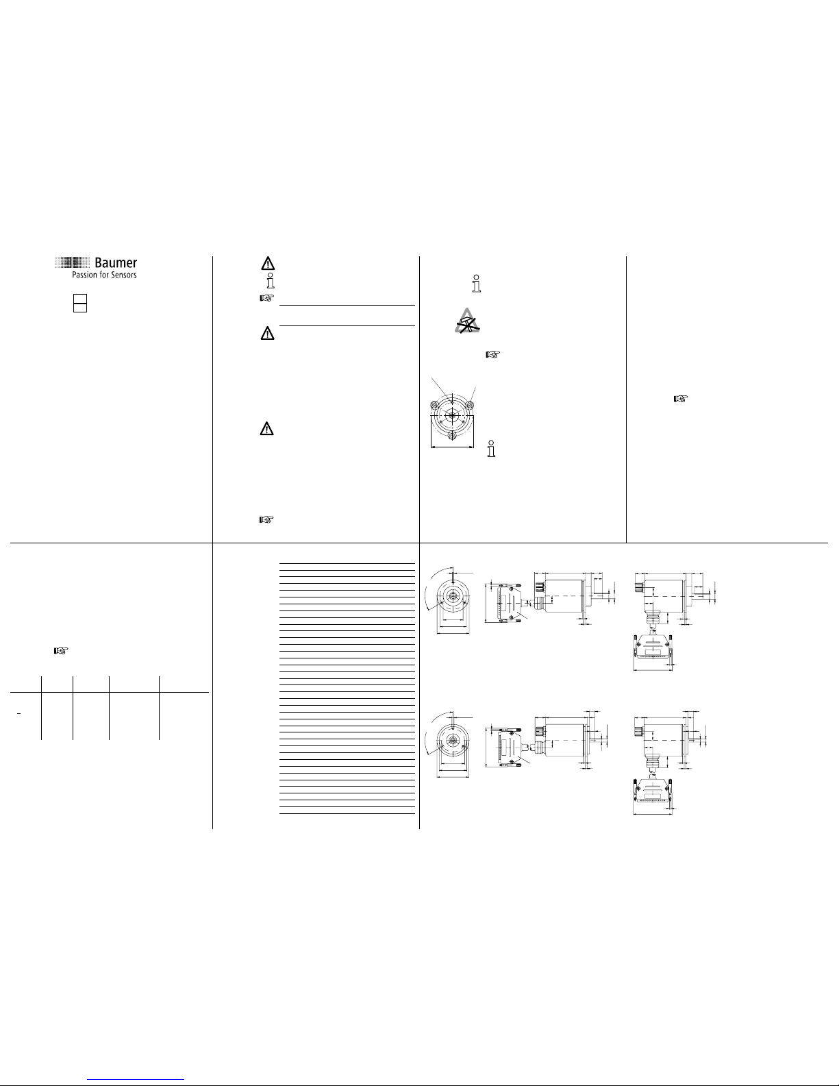
Klemmansch
Servoansch
M3 x 7
120°
36f8
48
±0.1
58
70
UNC 4 - 40
D-SUB
19
75
10
20
15
9
ø10h6
3
3
13
10
20
15
9
ø10h6
3
3
75
16
UNC 4 - 40
70
20
17.5
16
M4 x 7
120°
42
±0.1
50h7
58
70
UNC 4 - 40
D-SUB
19
75
10
4
9
5.5
ø 6f6
3
3
13
75
10
4
9
5.5
ø 6f6
3
3
16
20
UNC 4 - 40
70
17.5
16
GeberFunktion
5-pol.
Geber-St.
Kabelfarbe PC-Anschluss
9-pol. D-SUB
PC-Anschluss
25-pol. D-SUB
RxD
GND
P/R
Mode
TxD
-
-
PIN 1
PIN 2
PIN 3
PIN 4
PIN 5
-
-
braun
weiss
blau
schwarz
grau
-
-
PIN 3
PIN 5
PIN 5
PIN 2
Brücke 4-6
Brücke 7-8
PIN 2
PIN 7
PIN 7
PIN 3
Brücke 4-5
Brücke 6-20
Drehgeber zusätzlich über 37-poligen Gerätestecker an Spannung (UB/rot/Pin 36
und GND/blau/Pin 37) anschliessen.
Page 2
10
11 12
14 15 1613
9
Danger
Warnings of possible danger.
General instructions
Information on appropriate product handling.
General remarks
Additional information
The installation instruction is supplementary to already
existing documentation (catalog, data sheet and manual).
It is imperative to read the manual carefully prior to starting the device.
Appropriate use
- The encoder is a precision measuring device. It is expli-
citly designed for registration of angular positions and
revolutions as well as evaluation and supply of measuring values as electric output signals for the subsequently connected device. The encoder must not be used for
any other purpose.
Start up
- Installation and assembly of the encoder only by electri-
cally skilled and qualied personnel.
- Consider also the operation manual of the machine
manufacturer.
Safety instructions
- All electrical connections are to be revised prior to star-
ting the system.
- Incorrect assembly and electrical connections or any
other inappropriate work at encoder and system may
lead to malfunction or failure of the encoder.
- Any risk of personal injury, damage of the system or
company equipment due to failure or malfunction of the
encoder has to be eliminated by corresponding safety
measures.
- Do not operate encoder beyond the limit values stated
in the data sheet.
Any disregard may lead to malfunctions, material damage
and personal injury.
Fixing bore
Eccentric
xing
69
Disposal
Encoder components are to be disposed of according to
the regulations prevailing in the respective country.
Transport and storing
- In original packing only.
- Do not drop or expose encoder to major shocks.
Assembly
- Avoid punches or shocks on case and shaft.
- Avoid case distortion.
- Do not use any rigid links between encoder shaft and
drive shaft.
- Do not open or modify encoder in any mechanical way.
Shaft, bearing, glass disc or electronic components
might be damaged and a secure operation is no
longer guaranteed.
Mechanical assembly
- Mount encoder using three screws using the three xing
bores of the ange. Consider the depth and diameter of
the thread.
- Alternative mounting in any angular position is possible
by means of three eccentric xings (accessories).
- Use appropriate coupling to link drive shaft and encoder
shaft. For appropriate links please refer to accessories.
The ends of the shafts must not touch each other.
Any displacements due to temperature or mechanical tolerances have to be equalized by the
coupling. Mind the maximum permitted axial or
radial shaft load. Tighten xing screws rmly.
GXP1W
Absolute Encoder – Parallel 9-16
Assembly Instructions
GB
Electrical installation
- Do not modify encoder in any electrical way and carry
out any wiring work under power supply.
- Any electrical connection and plugging-on whilst under
power supply is not permitted.
- A separate encoder supply has to be provided with con-
sumers with high interference emission.
- Encoder case and supply cable have to be completely
screened.
- Installation of the whole system has to be according
to EMC standards. Installation environment as well as
wiring have an impact on the encoder’s EMC. Encoder
and supplying lines are to be in separated locations or
remote from lines with high interference emission (frequency transformers, protections, etc.).
- Ground (PE) encoder by using screened cables. The
braided shield has to be connected to cable gland or
plug. Grounding (PE) on both sides is recommended.
Ground the case by the mechanical assembly, if latter
is electrically isolated a second connection has to be
provided. Ground cable screen by the subsequently
connected devices. In case of ground loop problems at
least grounding on one side is imperative.
Any disregard may lead to malfunctions, material damage
and personal injury.
Electrical Connection
- Any outputs not used must not be connected.
Unused cable cores have to be isolated.
- After the reset process the zero input should be groun-
ded (GND) externally for better protection against interferences. The encoder must not be programmed during
operation.
- Maximum bending radius 90 mm.
- Mating connector for connecting cable available as
spare part, please see accessories.
- In case of using any customer-specic cables apply
only shielded lines and connectors according to EMC
standards. Consider the assembly instructions of the
respective supplier.
Pin assignment
Plug Wire color Assignment
Pin 1 white output D0
Pin 2 brown output D1
Pin 3 green output D2
Pin 4 yellow output D3
Pin 5 gray output D4
Pin 6 pink output D5
Pin 7 black output D6
Pin 8 violet output D7
Pin 9 gray/pink output D8
Pin 10 red/blue output D9
Pin 11 white/green output D10
Pin 12 brown/green output D11
Pin 13 white/yellow output D12
Pin 14 yellow/brown output D13
Pin 15 white/gray output D14
Pin 16 gray/brown output D15
Pin 17 white/pink output D16
Pin 18 pink/brown output D17
Pin 19 white/black output D18
Pin 20 brown/black output D19
Pin 21 gray/green output D20
Pin 22 yellow/gray output D21
Pin 23 pink/green output D22
Pin 24 yellow/pink output D23
Pin 25 – –
Pin 26 – –
Pin 27 yellow/blue Zero
Pin 28 brown/blue ENABLE inv.
Pin 29 brown/red STORE inv.
Pin 30 green/blue UP/DOWN
Pin 31 – –
Pin 32 – –
Pin 33 – –
Pin 34 white/blue GND-Sense
Pin 35 white/red UB-Sense
Pin 36 red UB
Pin 37 blue GND
Conguration and Parameter Setting
Accessories required:
- PC with RS232 interface and Windows operation
system.
- ProGeber software and two adaptor cables, refer also
to accessories.
- Connect PC to the encoder’s programming interface by
using the programming cable.
- Tighten both nut of the C-connector as well as locking
screws of the SUB-D plug as far as possible.
- Connect encoder to power supply by the adaptor cable.
- Switch on power supply.
For encoder conguration and parameterizing please
refer to the respective manual.
Connection assignment of programming cable
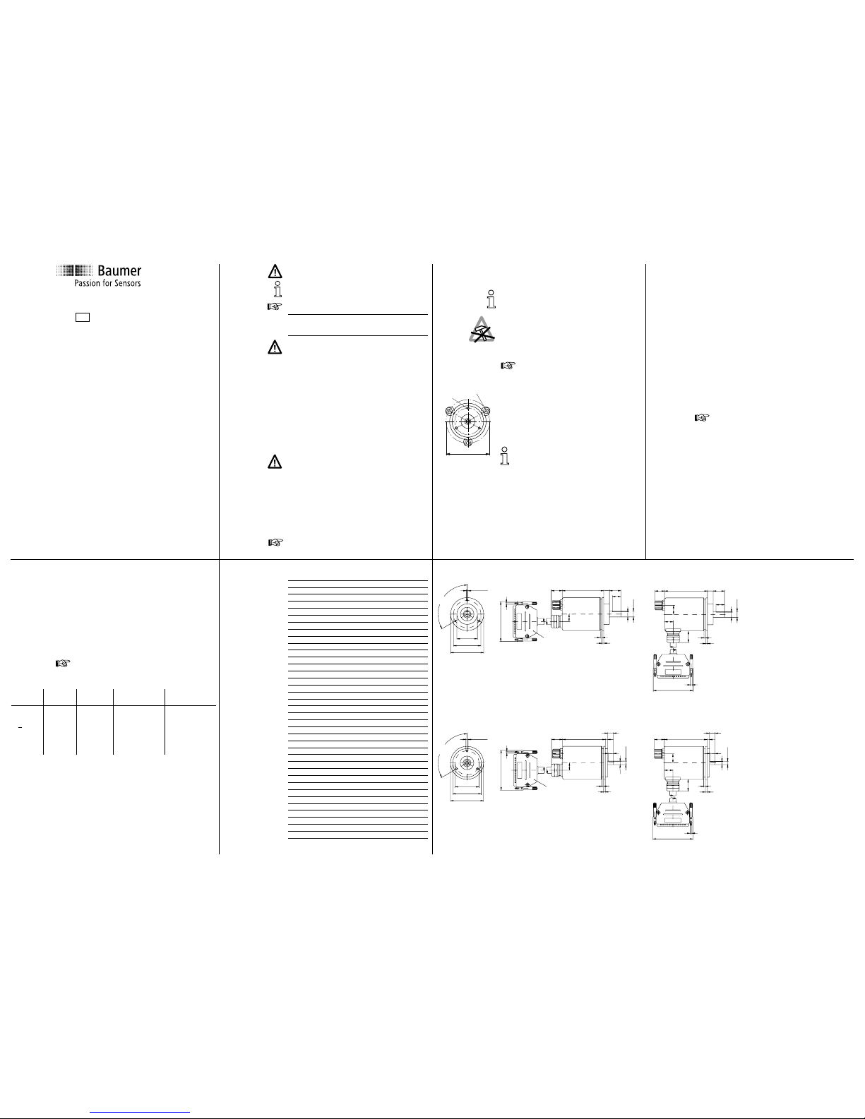
Dimensions
Clamping ange
Synchro ange
M3 x 7
120°
36f8
48
±0.1
58
70
UNC 4 - 40
D-SUB
19
75
10
20
15
9
ø10h6
3
3
13
10
20
15
9
ø10h6
3
3
75
16
UNC 4 - 40
70
20
17.5
16
M4 x 7
120°
42
±0.1
50h7
58
70
UNC 4 - 40
D-SUB
19
75
10
4
9
5.5
ø 6f6
3
3
13
75
10
4
9
5.5
ø 6f6
3
3
16
20
UNC 4 - 40
70
17.5
16
encoder
function
enc. plug
5-pin
cable
color
PC contact
9-pin D-SUB
PC contact
25-pin D-SUB
RxD
GND
P/R
Mode
TxD
-
-
pin 1
pin 2
pin 3
pin 4
pin 5
-
-
brown
white
blue
black
gray
-
-
pin 3
pin 5
pin 5
pin 2
bridge 4-6
bridge 7-8
pin 2
pin 7
pin 7
pin 3
bridge 4-5
bridge 6-20
Also connect encoder via device plug (37-pin) to voltage (UB/red/pin 36 and
GND/blue/pin 37).
 Loading...