


OPERATOR MANUAL
®
BASIL
Cage and Rack Washer
(2004-06-29) P920017-148
9502

A WORD FROM STERIS CORPORATION
This manual contains important information on the proper use of this equipment.
Refer to Section 6,
washer. All personnel and department heads are urged to carefully review and
become familiar with the
These instructions should be retained in a conveniently accessible area for quick
reference. This equipment is specifically designed only for the uses outlined in
this manual.
Routine Maintenance
Safety Precautions
, for instructions in routine care of this
and instructions contained herein.
Advisory
IMPORTANT: A listing of the
this washer can be found in Section 1. Do not operate the equipment until you have
become familiar with this information.
STERIS does not intend, recommend, or represent in any way that this
Basil® 9502 Cage and Rack Washer be used for the sterilization of any animal
care or other device which has been contaminated with pathogenic microorganisms.
Any alteration of the washer not authorized or performed by STERIS which could
affect its operation will void the warranty, could adversely affect washing efficacy,
could violate national, state, and local regulations, and could jeopardize your
insurance coverage.
To help assure operators are adequately trained in the safe use of the equipment,
STERIS recommends:
– all personnel who operate or maintain the equipment are trained in its
operation and in its safe use;
– personnel working with toxic chemicals and vapors (if applicable) have
comprehensive instructions in the washer disinfector process, relevant
health hazards, and methods to detect the escape of toxic materials;
– there is regular training of all personnel concerned with the operation and
maintenance of the equipment; attendance records are maintained; and
that evidence of understanding is demonstrated.
Safety Precautions
to be observed when operating
The Basil 9502 Cage and Rack Washer is intended for use in the sanitation of
Indications for Use
©2004, STERIS Corporation. All rights reserved. Printed in Canada
Table of Contents Operator Manual 920017-148
soiled, reusable animal care devices such as cages, racks, debris pans,
feeder bottles, and other miscellaneous items by providing thorough cleaning,
and optional drying.
This washer is specifically designed to only process goods as outlined in this
manual. If there is any doubt about a specific material or product, contact the
manufacturer of the product for recommended washing technique.
i

Service Information
Certification
A thorough preventive maintenance program is essential for safe and proper
equipment operation. You are encouraged to contact STERIS concerning
extended service maintenance agreements to give your equipment planned
maintenance.
A global network of skilled service specialists can provide periodic inspections
and adjustments to assure low-cost peak performance. STERIS can provide
information regarding the Annual Maintenance Agreements.
STERIS carries a complete line of accessories for use in this equipment. A STERIS
representative will gladly review these with you.
See inside back cover for contact information.
This Basil 9502 Cage and Rack Washer complies with the following
standards:
• Underwriters Laboratories (UL):
Standard 61010A-1.
• Canadian Standards Association (CSA):
Standard CAN/CSA C22.2 No. 1010.1.
Governing Directive for the Affixing of the CE Mark:
• Machinery Directive (98/37/CE).
Conformity to Other Applicable Directives:
• Low Voltage Directive (73/23/EEC) and amendment (93/68/EC).
• Electromagnetic Compatibility Directive (89/336/EEC) and amendments
(91/263/EEC, 92/31/EEC, and 93/68/EEC).
Standards applied to demonstrate conformity to the directives:
• EN/IEC-61010-1; EN/IEC-61010-2-045; EN/IEC-61326-1.
ii
920017-148 Operator Manual Table of Contents

TABLE OF CONTENTS
Section Title Page
A WORD FROM STERIS CORPORATION ............................................ i
Advisory ................................................................................................................................. i
Indications for Use ................................................................................................................. i
Service Information ................................................................................................................ ii
Certification ............................................................................................................................ ii
1 SAFETY PRECAUTIONS AND SYMBOLS ....................................... 1-1
1.1 Symbols on Unit ........................................................................................................... 1-4
1.2 Symbols on Nameplate ............................................................................................... 1-5
2 INSTALLATION VERIFICATION ...................................................... 2-1
2.1 Technical Specifications ............................................................................................... 2-1
2.1.1 Voltage and Amperage ........................................................................................ 2-1
2.1.2 Noise Level .......................................................................................................... 2-1
2.1.3 Permissible Environmental Conditions ................................................................. 2-1
2.2 Installation Checklist .................................................................................................... 2-2
2.3 Chemical Additives Specifications ............................................................................... 2-4
2.3.1 General ................................................................................................................ 2-4
2.3.2 Recommended Chemical Additives..................................................................... 2-4
3 COMPONENT IDENTIFICATION ...................................................... 3-1
3.1 General ........................................................................................................................ 3-1
3.2 Control Location ........................................................................................................... 3-2
3.2.1 LOCK/UNLOCK/INIT Key Switch ......................................................................... 3-2
3.2.2 POWER-OFF/STANDBY Switch ............................................................................ 3-2
3.3 Load-Side (Main) Control Panel ................................................................................... 3-3
3.3.1 Display Screen ..................................................................................................... 3-3
3.3.2 Touch Pads .......................................................................................................... 3-3
3.3.3 Printer ................................................................................................................... 3-4
3.4 Unload-Side (Remote) Control Panel ........................................................................... 3-8
3.5 Emergency Safety Features ........................................................................................ 3-8
3.5.1 Photoelectric Sensors .......................................................................................... 3-8
3.5.2 Emergency Exit Safety Doors .............................................................................. 3-9
3.5.3 Emergency Stop Cables ...................................................................................... 3-9
3.5.4 Emergency Stop Pushbuttons ............................................................................. 3-9
3.5.5 Interior Light ......................................................................................................... 3-9
3.5.6 Safety Delay ........................................................................................................ 3-9
3.5.7 LOCK/UNLOCK/INIT Key Switch ........................................................................3-10
4 OPERATING INSTRUCTIONS .......................................................... 4-1
4.1 Before Operating Washer............................................................................................ 4-1
4.2 Priming Procedure ....................................................................................................... 4-2
4.3 Doors .......................................................................................................................... 4-3
4.3.1 Door Operation ..................................................................................................... 4-3
4.3.2 Interlock Feature .................................................................................................. 4-4
4.3.3 Opening Doors during a Power Failure................................................................. 4-4
Table of Contents Operator Manual 920017-148
iii

TABLE OF CONTENTS (Cont'd)
Section Title Page
4.4 Accessories ................................................................................................................ 4-5
4.4.1 General ................................................................................................................ 4-5
4.4.2 How to Load Accessories Into Wash Chamber .................................................... 4-5
4.4.3 How to Load Central Header Manifold with Rodent Cage Racks (Accessory) ..... 4-7
4.4.4 How to Load Bottle Washing Cart or Universal Cage and Pan Wash Cart
(Accessory) ........................................................................................................ 4-9
4.5 Typical Cycle Operation .............................................................................................4-10
4.6 DRAIN Cycle ..............................................................................................................4-13
4.7 Pause Cycle Operation ............................................................................................. 4-15
4.8 Abort Cycle Operation ...............................................................................................4-16
4.9 Acknowledge Alarm Condition ................................................................................... 4-17
4.10 Shutdown ................................................................................................................. 4-18
4.10.1 Manual Shutdown ..............................................................................................4-18
4.10.2 Automatic Shutdown .........................................................................................4-19
5 CYCLE AND CONTROL VALUE PROGRAMMING ........................... 5-1
5.1 General ....................................................................................................................... 5-1
5.2 Change Values Mode .................................................................................................. 5-3
5.2.1 Sequence of Display Screens .............................................................................. 5-3
5.2.2 How to Modify a Cycle ......................................................................................... 5-3
5.3 Review Cycle Values .................................................................................................. 5-12
6 ROUTINE MAINTENANCE ............................................................... 6-1
6.1 Preventive Maintenance Schedule .............................................................................. 6-1
6.2 Cleaning Procedures ................................................................................................... 6-3
6.2.1 Daily Cleaning ...................................................................................................... 6-3
6.2.2 Weekly Cleaning .................................................................................................. 6-5
6.2.3 Horizontal Spray Headers and Spray Jets .......................................................... 6-7
6.2.4 Central Header Manifold (Option)......................................................................... 6-7
6.2.5 Rotary Spray Arms on Bottle Washing Cart (Option) ........................................... 6-9
6.2.6 Building Supply Line Strainers ............................................................................. 6-9
6.2.7 Vertical Self-Cleaning Filters................................................................................ 6-10
6.3 Descaler Cycle ..........................................................................................................6-12
6.3.1 Manual Descaler Cycle ....................................................................................... 6-12
6.3.2 Automatic Descaler Cycle (Option) .....................................................................6-15
6.4 Chemical Container Replacement .............................................................................. 6-18
6.5 Injection Pumps Lubrication and Squeeze Tube Replacement ..................................6-19
6.6 Printer Paper Roll Replacement .................................................................................6-20
6.6.1 Procedure ...........................................................................................................6-21
6.6.2 Thermal Paper Storage ........................................................................................6-22
7 TROUBLESHOOTING....................................................................... 7-1
8 REPLACEMENT PARTS AND PRODUCTS ...................................... 8-1
iv
920017-148 Operator Manual Table of Contents

SAFETY PRECAUTIONS AND SYMBOLS
1
The following
the potential for personal injury and CAUTION indicates the potential for danger to equipment. These
are repeated, where applicable, throughout the manual. It is important to review these
operating or servicing the unit.
Strictly following these
customer to avoid improper maintenance methods which could damage the unit or render it unsafe. It is important to
understand that these
policies and procedures to enhance and compliment these Safety Precautions.
Safety Precautions
Safety Precautions
Safety Precautions
mustmust
must be observed when operating and servicing this equipment. WARNING indicates
mustmust
Safety Precautions
Safety Precautions
enhances your ability to safely and effectively utilize the unit and allows the
are not exhaustive; customers are encouraged to develop their own safety
before
WARNING – PERSONAL INJURY AND/OR EQUIPMENT DAMAGE HAZARD:
Always wear appropriate Personal Protective Equipment (PPE) when cleaning or removing debris from bottom of
the wash chamber and over the suction plate.
Before servicing or cleaning exterior of unit, always turn LOCK/UNLOCK/INIT key selector to LOCK position to
de-energize unit. Keep the key on yourself.
Only fully qualified service personnel should make repairs and adjustments to this equipment. Maintenance done
by inexperienced, unqualified personnel or installation of unauthorized parts could cause personal injury,
invalidate the warranty, or result in costly damage. Contact STERIS regarding service options.
Regularly scheduled preventive maintenance, in addition to the faithful performance of the minor maintenance
described within this manual, is required for safe and reliable operation of this equipment. Contact STERIS to
schedule preventive maintenance.
To open doors from inside wash chamber, pull EMERGENCY STOP cables. Washer operation will automatically
stop. Then, push firmly between door panels using shoulder and upper arm, applying upper body force. Do not
push between the two doors, but between the door panels.
To test or demonstrate Emergency Exit Safety Doors, first press EMERGENCY STOP pushbutton (located under
control) or EMERGENCY STOP cables (inside wash chamber) to turn power OFF. If power is still on while adjusting
or servicing doors, the photoelectric sensor will detect the movement of the door panels and doors will open
automatically.
WARNING – PERSONAL INJURY HAZARD:
If doors are still slightly open (less than 2 inches [5 cm]) when power is restored after a power failure, control will
apply pressure to complete closing. Lock building electrical supply disconnect switch in OFF position and close
unit air supply when opening doors after a power failure.
Keep hands/fingers away from closing doors to prevent crushing between the two doors.
Never perform cleaning of wash chamber until full cycle has been completed. If cycle has not been completed,
contaminated debris or water may remain in the bottom of the wash chamber
When doors are closing, a pinch point is created at the hinges. Keep fingers away from door hinges to prevent
pinching.
(See next page for additional Safety Precautions)
Safety Precautions and Symbols Operator Manual 920017-148
1-1

WARNING – ELECTRICAL SHOCK AND/OR BURN HAZARD:
Disconnect all utilities to washer before servicing. Do not service washer unless all utilities have been properly
locked out. Always follow local occupational health and safety regulations, as well as electric and plumbing codes.
WARNING – BURN HAZARD:
After pressing STOP/RESET touch pad, wait until water flow stops before opening doors. Hot water/steam may
be sprayed through door opening if doors are opened too soon.
Except for emergency, do not open door when cycle is in progress. In an emergency, first stop cycle by pressing
the EMERGENCY STOP pushbutton and wait for water flow to stop. Wear appropriate Personal Protective
Equipment (PPE) whenever reaching into or entering wash chamber.
Inner surfaces of washer are very hot after cycle completion. Operator should wear appropriate Personal Protective
Equipment (PPE) and avoid all contact with inner walls when entering chamber to unload washer.
WARNING – SLIPPING HAZARD:
To avoid slippery floor conditions, immediately wipe up any spilled liquids or condensation.
WARNING – CHEMICAL BURN AND/OR EYE INJURY HAZARD:
Always use non-foaming chemical for effective cleaning and proper pump and water level control operation. Follow
manufacturer's recommendations for amount of chemical to be used.
Detergents are caustic and can cause adverse effects to exposed tissues. Do not get in eyes, on skin or attempt
to swallow.
• Read and follow the precautions and instructions on the detergent label and in the Material Safety Data Sheet
(MSDS) prior to handling detergent containers, or servicing the detergent injection pumps and lines.
• Wear appropriate Personal Protective Equipment (PPE) whenever handling chemicals or servicing chemical
injection pumps and lines.
Wear appropriate Personal Protective Equipment (PPE) when using a descaling product. Avoid contact with eyes
or skin. If spilled or splashed, flush with water for 15 minutes. If swallowed, DO NOT induce vomiting. Administer
an alkali with plenty of water. Seek medical attention immediately.
CAUTION – POSSIBLE EQUIPMENT DAMAGE:
Always leave plenty of space between load and doors. Leaning load against doors will damage doors and also
prevent them from opening or closing.
Always use a silicone lubricant to lubricate squeeze tubes. Petroleum-based lubricants, such as Vaseline or
grease, will cause squeeze tubes to melt.
Avoid product damage. Always select a cycle appropriate for the items being processed.
Before operating the unit, always position manifolded Bottle Washing Cart and/or Central Header Manifold over
central water inlet connector. If manifolded accessory is not positioned correctly, damage may result and unit will
be unable to effectively wash load.
(See next page for additional Safety Precautions)
1-2
920017-148 Operator Manual Safety Precautions and Symbols

CAUTION – POSSIBLE EQUIPMENT DAMAGE (Cont'd):
Do not process load using Central Header Manifold or Bottle Washing Cart in a chamber where Automatic Floor
Tilting option is activated. If Automatic Floor Tilting is used, manifolded water inlet and washer will be damaged.
Keep away from doors to prevent load detection sensor from stopping doors from closing.
Remove all cellulose-type bedding from cages and pans before processing. Cellulose bedding can clog filters
and piping.
Use non-abrasive cleaners when cleaning unit. Follow directions on containers and rub in a back-and-forth motion,
in same direction as surface grain. Abrasive cleaners will damage stainless steel. Cleaners rubbed in a circular
motion or applied with a wire brush or steel wool on door and chamber assemblies can be harmful to stainless steel.
Do not use these cleaners on painted surfaces.
When choosing a chemical, select one with a low chloride content. Chloride is harmful to stainless steel and will
deteriorate washer.
Safety Precautions and Symbols Operator Manual 920017-148
1-3
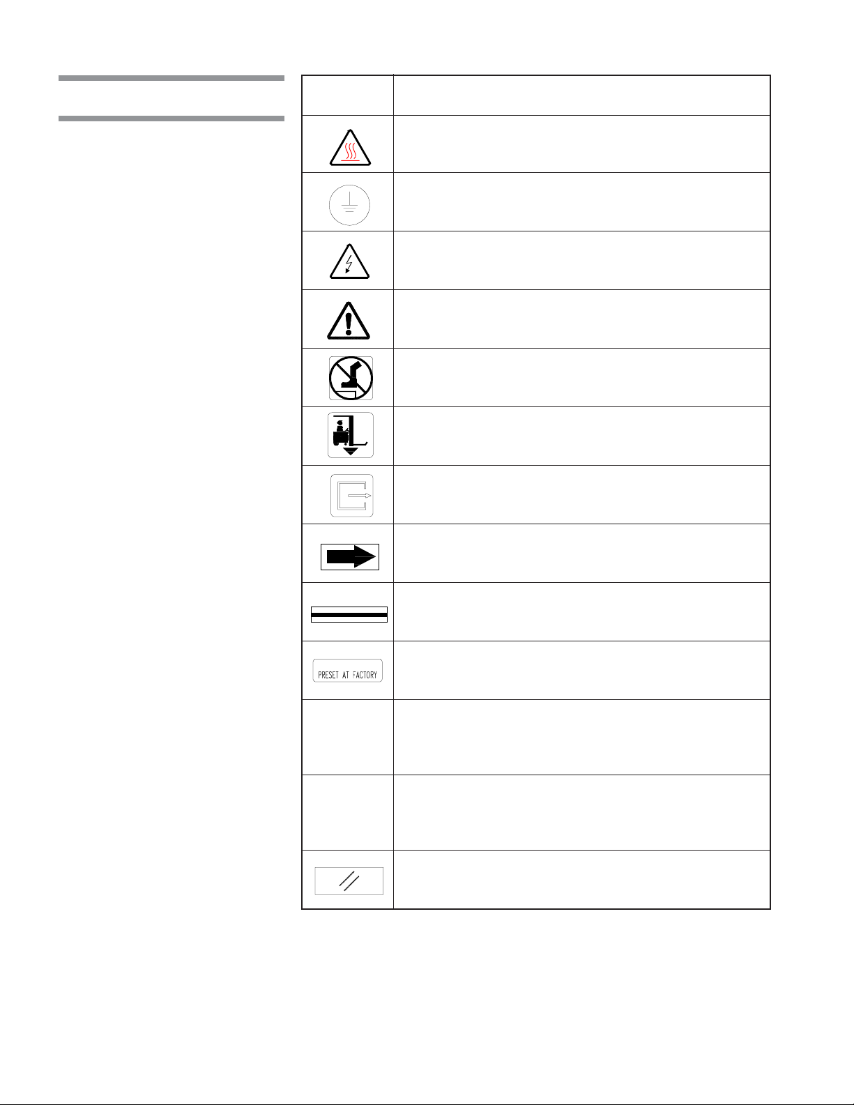
1.1 Symbols on Unit
Symbol Definition
Transfer of Heat, Hot Surface.
Protective Earth (Ground).
Warning! Risk of Electrical Shock.
Warning. Refer to Manual for Further Instructions.
Warning! Do Not Step Here.
Fork Lift: Place Forks of The Fork Lift Here.
Safety Exit: Push Here in Case of an Emergency.
Rotation: Direction of the Rotating Device.
Load Delimitation: Do Not Place Load Over These Marks.
Factory Adjustment: Do Not Adjust.
² Unlock and Energize Unit.
± Lock and De-Energize Unit.
Initialize/Reset Unit.
1-4
920017-148 Operator Manual Safety Precautions and Symbols

1.2 Symbols on Nameplate
Symbol Definition
MODEL Model Number of the Unit.
S/N Serial Number of the Unit.
kVA Kilovolt-Ampere.
V__~ Volt, Number of Phase (3 or 1 [blank]),
Alternate Current.
A Ampere.
YEAR Year of Manufacture of the Unit.
Hz Hertz – Frequency of the Unit.
WIRE Number of Wires in the Electrical Cable
(Ground Not Included).
Safety Precautions and Symbols Operator Manual 920017-148
1-5

INSTALLATION VERIFICATION
2
2.1 Technical
Specifications
2.1.1 Voltage and Amperage
IMPORTANT: A listing of the
and servicing this equipment can be found in Section 1 of this manual. Do not
operate or service the equipment until you have become familiar with this
information.
These specifications are intended to describe the technical information given
on the nameplate of your washer and to state other relevant information. Check
Equipment Drawing or Identification nameplate, located on frame of mobile
mechanical core, below main electrical box, for proper voltage and amperage.
This unit operates on:
• 380/400/415 V~, 3-phase, 50 Hz
• 480 V~, 3-phase, 60 Hz.
• 208 V~, 3-phase, 60 Hz (with the optional transformer).
A protective ground conductor is required (Class 1 Equipment). Installation
Category is Overvoltage II.
Refer to
Uncrating/Installation Manual
Safety Precautions
(P920017-147) for proper connection.
to be observed when operating
2.1.2 Noise Level
2.1.3 Permissible
Environmental Conditions
IMPORTANT: Customer responsible for compliance with applicable codes and
regulations.
The maximum currents and power consumptions, for units with or without
drying, are:
kW A
• 380/400/415 V 18,6 26
• 480 V 28,3 34
Equivalent Sound Pressure Level at work station (measured 3 ft. [1 m] away from
equipment and at 5 ft [1.6 m] from ground): 76.6 dB (A) for a freestanding unit
with side panels (Results determined according to
Acoustics Determination of Sound Power Levels of Noise Sources Survey
Method
This washer is designed to give optimal results in an environment where
maximum relative humidity is less than 85% and maximum operating temperature is 104°F (40°C).
).
ISO-3746: 1979 Standard:
2-1
Installation Verification Operator Manual 920017-148

2.2 Installation Checklist
An Equipment Drawing, showing all utility and space requirements, was sent to
you after the order for this equipment was received. The clearance space,
specified on Equipment Drawing (P920502-212), is necessary for proper
installation, operation, and maintenance.
(P920017-147) were provided with the washer. If any of these documents are
missing or misplaced, contact STERIS giving the serial, equipment, and model
numbers of the unit. Replacement copies will be sent to you promptly.
Uncrating/Installation Instructions
After installing the washer according to the
tions
(P920017-147), complete the following checklist to assure complete and
correct installation, or contact STERIS to schedule a technician to test your
installation and demonstrate proper equipment operation.
❑ Shutoff valves (not provided by STERIS), for maintenance purposes and
capable of being locked in OFF position only, are installed on steam, air, and
water lines and are in compliance with local occupational health and safety
regulations, as well as plumbing codes.
❑ Disconnect switches (not provided by STERIS), for maintenance purposes
and capable of being locked in OFF position only, are installed on electrical
supply lines near the unit and are in compliance with local occupational health
and safety regulations, as well as electric codes. Disconnect switches must
bear the identification of the equipment to which they are connected.
Uncrating and Installation Instruc-
NOTE: If unit is installed next to other equipment, shutoff valves and disconnect
switches should be located so that service can be shut off to one piece of
equipment at a time.
❑ Washer positioned as shown on Equipment Drawing and with required
clearance space and in relation to building supply lines.
❑ Washer and two mechanical cores are level. Use shims or Leveling Legs (if
accessory is present) if necessary.
❑ If Drain Discharge Cooldown System or pH Neutralizing System option is
present, building cold water line supplies water to unit as specified on
Equipment Drawing.
❑ Building hot water line supplies water to unit as specified on Equipment
Drawing.
❑ Building steam line provides steam to unit as specified on Equipment
Drawing.
❑ Building condensate return line is connected to washer as specified on
Equipment Drawing.
❑ Building air line supplies air to unit as specified on Equipment Drawing.
❑ Building waste line is connected to washer as specified on Equipment
Drawing.
❑ Building ventilation system is connected to washer as specified on Equip-
ment Drawing.
❑ Electrical supply for unit is as specified on Equipment Drawing.
❑ Piping connections between washer, main mechanical core, and secondary
mechanical core are as specified in Section 3 of
Instructions
(P920017-147).
Uncrating/Installation
2-2
920017-148 Operator Manual Installation Verification

❑ Electrical connections between washer, main mechanical core, and second-
ary mechanical core are as specified in Section 3 of
Instructions
(P920017-147).
Uncrating/Installation
❑ Air line connections between washer, main mechanical core, and secondary
mechanical core are as specified in Section 3 of
Instructions
(P920017-147).
Uncrating/Installation
❑ If Drying System option is present, drying connections between washer, main
mechanical core, and secondary mechanical core are as specified in Section
3 of
Uncrating/Installation Instructions
(P920017-147).
❑ If Floor Ramp accessory is present, floor ramp is correctly attached to washer
as specified in Section 3 of
Uncrating/Installation Instructions
(P920017-147).
❑ If Service Side Access Panels accessory is present, service side access
panels are correctly attached to washer as specified in Section 3 of
Installation Instructions
(P920017-147).
Uncrating/
❑ Floor surrounding unit has nonslip surface.
IMPORTANT: After a few weeks of operation, inspect units for leaks. Retighten
all clamps and connections.
2-3
Installation Verification Operator Manual 920017-148

2.3 Chemical
Additives
Specifications
2.3.1 General
The selection of chemical additives is open for customer preference. However,
in order to achieve optimal performance, the selected chemical additives must
meet as a minimum, the following specifications:
Product Use Dilution pH Range Other Applicable
Description Range oz/gal at Use Dilution Requirements
(mL/L)
Alkaline 1/4 - 4 9.0 - 12.0 Liquid, non foaming, and viscosity below 200 ccsu.
Chemicals (2 - 32)
Acidic 1/4 - 4 3.0 - 6.0 Liquid, non foaming, free rinsing, and viscosity
Chemicals (2 - 32) below 200 ccsu.
Descalers 1/2 - 2 < 2.5 Liquid, non foaming, phosphoric acid-based, and
(4 - 16) viscosity below 200 ccsu.
NOTE: When choosing and using detergents, note the following:
1) Follow chemical label recommendations for concentration of chemical to use.
2) Follow chemical manufacturer's recommendations to determine the temperature of the WASH treatment.
3) Follow chemical manufacturer's recommendations for the amount of chemical
used according to water hardness.
2.3.2 Recommended Chemical Additives
WARNING – CHEMICAL
BURN AND/OR EYE INJURY
HAZARD: Always use nonfoaming chemical for effective cleaning and proper
pump and water level control operation. Follow
manufacturer's recommendations for amount of
chemical to be used.
2-4
920017-148 Operator Manual Installation Verification
To achieve maximum cleaning efficiency, select chemical appropriate to soil
type being processed. STERIS recommends the following chemicals:
• Cage-Klenz® 100 Alkaline Cage Wash Detergent – (Alkaline) formulated to
remove urine, scale, animal fats, oils, and other organic soils from cage
materials.
• Cage-Klenz® 200 Acid-Based Wash Detergent – (Acidic) formulated to
remove urine, scale, animal fats, oils, and other organic soils from cage
materials.
• LIQUID DESCALER LIQUID SCALE REMOVER – for removing scale and
other hard water deposits. For use in animal care centers.
NOTE: Certain products may not be available in your area. Contact STERIS for
availability of these products and for ordering information.
IMPORTANT: STERIS does not promote, recommend, or endorse the use of any
other type of chemical additives in the processing of articles in the Basil® 9502
Cage and Rack Washer, such as drying agents, strong alkaline detergents
(pH>12), alcohol rinses, and liquid germicides including hypochloric acid
(bleach).
COMPONENT IDENTIFICATION
3
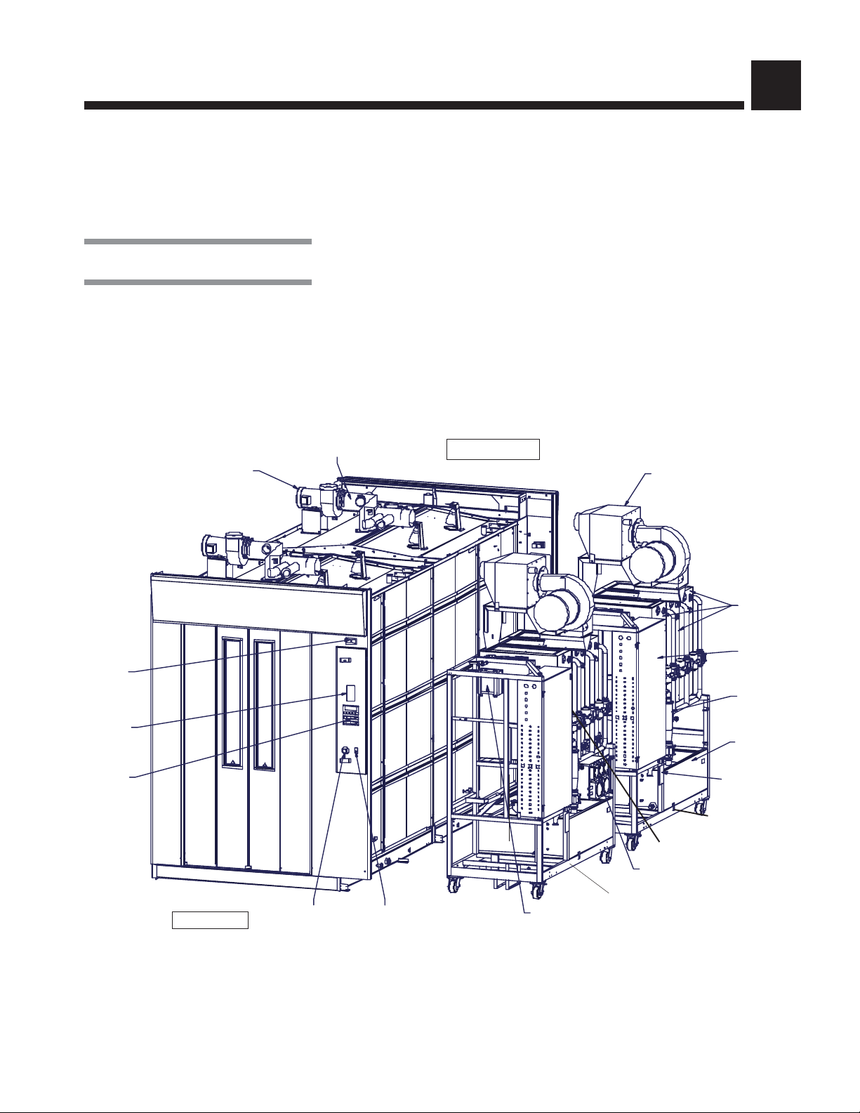
3.1 General
Exhaust
Fan
IMPORTANT: A listing of the
Safety Precautions
to be observed when operating
and servicing this equipment can be found in Section 1 of this manual. Do not
operate or service the equipment until you have become familiar with this
information.
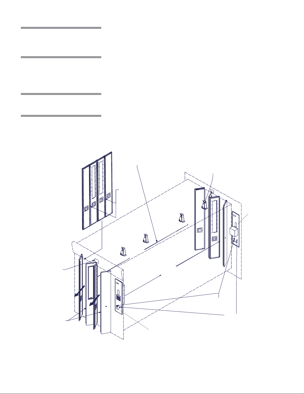
Become familiar with the location and function of all major components and
controls, as well as their function before operating this unit (see Figure 3-1).
Damper
UNLOAD SIDE
Drying
Option
Indicator
Lights
Printer
Control
Panel
Side
Tanks
Secondary
Electrical
Box
Vertical Self-
Cleaning
Filter
Cool Down
Tank
Identification
Nameplate
SECONDARY
MECHANICAL
CORE
Flowmeters
Main Electrical Box
MAIN MECHANICAL CORE
(Always on left when facing
service side)
Ref: # 920-501-294
LOAD SIDE
EMERGENCY
STOP
Pushbutton
Lock /
Unlock/Init
Switch
Electrical
Supply Box
Figure 3-1. Basil® 9502 Cage and Rack Washer (Typical)
3-1
Component Identification Operator Manual 920017-148
3.2 Control Location
Become familiar with all control locations and functions before operating the unit
(see Figures 3-1 and 3-2).
3.2.1 LOCK/UNLOCK/INIT Key Switch
3.2.2 POWER-OFF/ STANDBY Switch
LOCK/UNLOCK/INIT key switch is located on both control panel doors and
includes three positions :
± • LOCK – To lock washer for maintenance purposes, use key to turn
selector switch to the left. Positioning selector switch to LOCK position
places the washer in locked mode. The operator cannot start a new
cycle or enter into the Service mode.
² • UNLOCK
washer. Positioning switch to UNLOCK enables the washer to function
normally.
••
• INITIALIZATION
••
normal operation after Emergency Stop Cables or Emergency Stop
Button were activated, after a power up, or a power failure.
NOTE : Selector returns automatically from reset to UNLOCK position when key
is released.
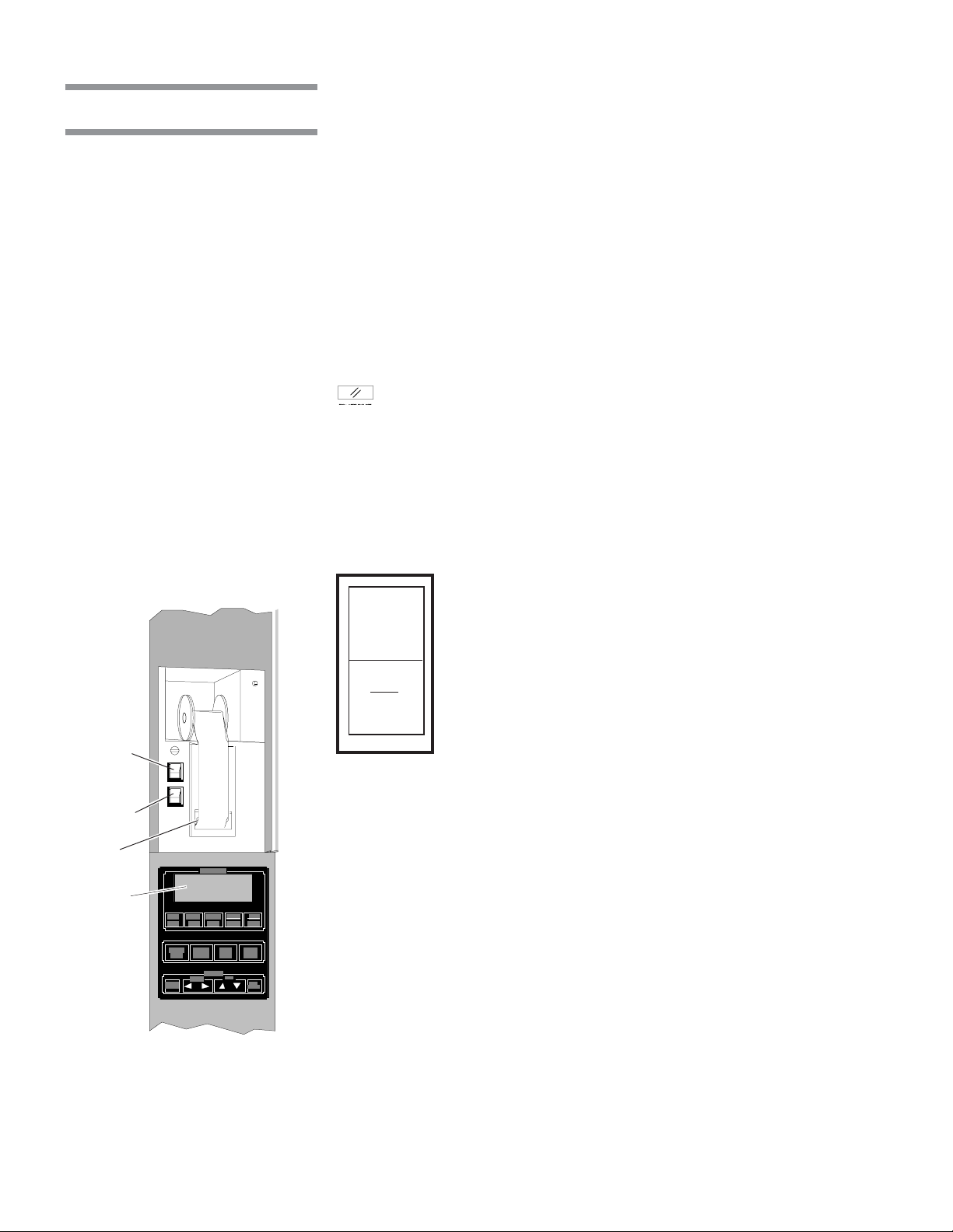
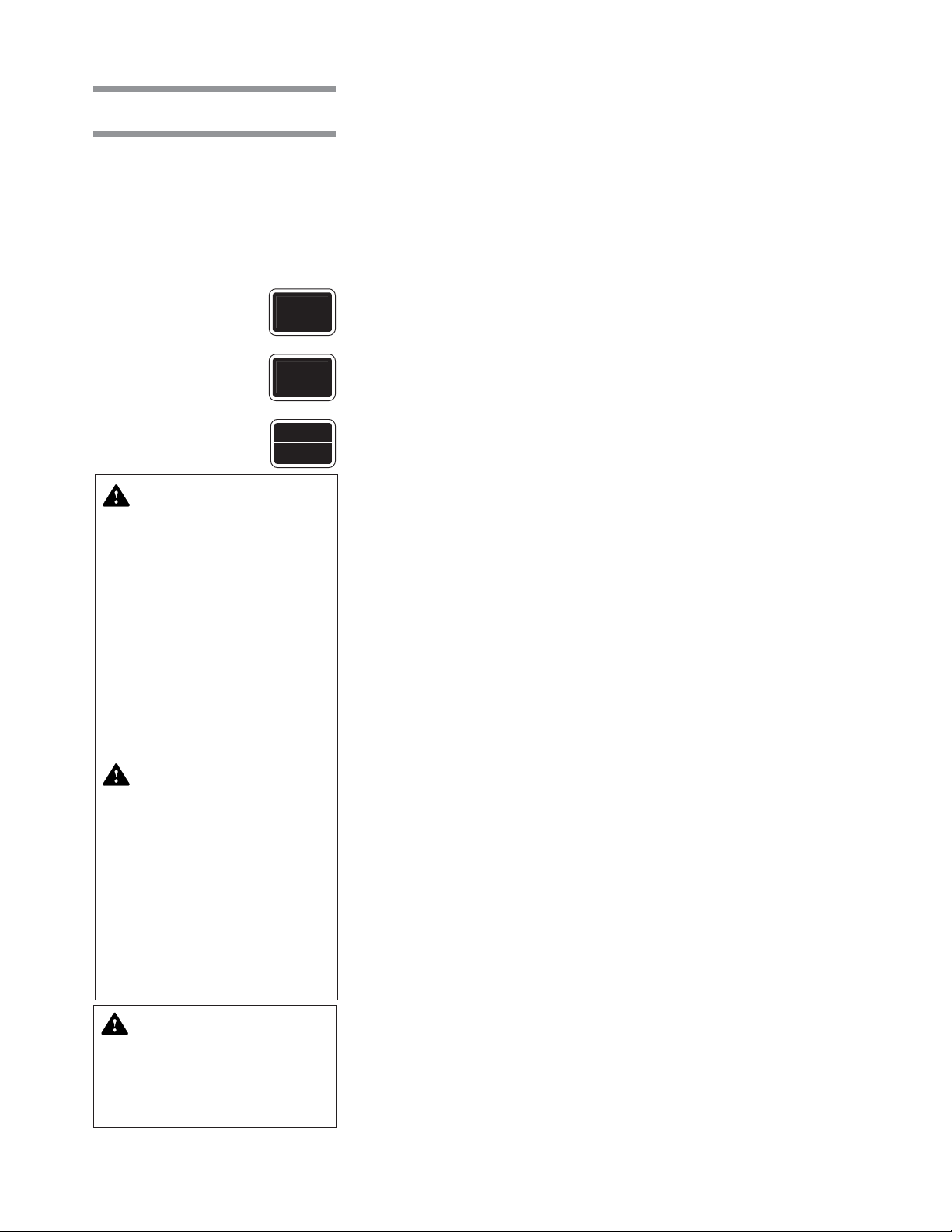
The POWER-OFF/STANDBY switch, located behind the printer door, includes
two settings which direct operation of the control (see Figure 3-1 and 3-2):
POWER
– Use key to turn selector switch to central position to unlock
– Use key to turn selector to the right to reset washer
• POWER – Press top portion of POWER-OFF/STANDBY
switch to initialize control and place control in Ready Mode.
POWER-
OFF/
STANDBY
Switch
PRINT/PRINT
VALUES
Switch
Printer
Display
Screen
Figure 3-2. Load End
Control Panel and Printer
OFF
• OFF/STANDBY – Press bottom portion of POWER-OFF/
STANDBY switch to initiate Shutdown Cycle and place
STANDBY
control in Standby Mode.
NOTE: Control should be placed in Standby Mode for last cycle of the day and
when washer is not in use for an extended period of time.
IMPORTANT: POWER-OFF/STANDBY switch does not turn off electrical power
to the unit.
3-2
920017-148 Operator Manual Component Identification
3.3 Load-Side
(Main) Control Panel
The Basil 9502 Cage and Rack Washer is equipped with a fully-programmable
microprocessor control system capable of storing up to 12 cycles for processing a wide variety of loads. The control system monitors and automatically
controls all cycle operations and functions.
The main control panel is used to direct all washer functions. It can be placed
on either the load side or the unload side (see Figures 3-1 and 3-3). The operator
may select and review cycles and treatments, start, stop, or reset cycle
operation, and monitor cycle performance and washer status from the control
panel.
3.3.1 Display Screen
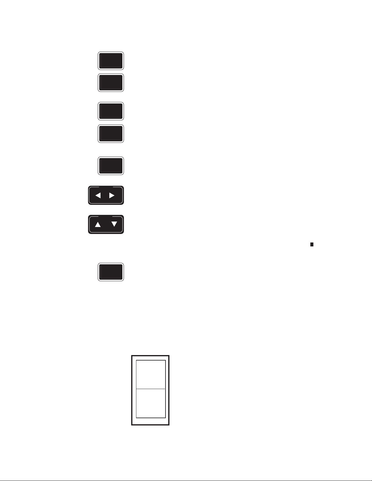
3.3.2 Touch Pads
CYCLE
MENU
SELECT
CYCLE
REVIEW
CYCLE
CYCLE
START
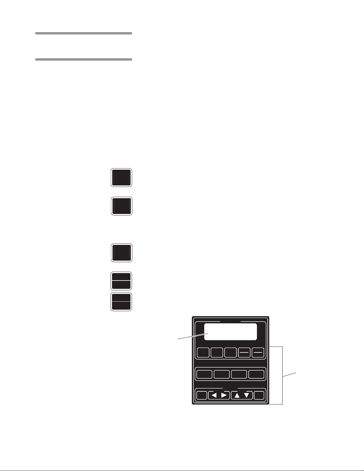
The two-line, alphanumeric screen displays cycle program data on demand,
cycle performance data and operator instructions. Display screen also indicates certain abnormal conditions that may occur during a cycle.
• Cycle Status Touch Pads:
CYCLE MENU Touch Pad – Press to view the cycle menus. Three cycle menus
are available.
SELECT CYCLE Touch Pad – Press to select one of the four cycles available
from each cycle menu.
NOTE: When a displayed cycle or treatment value is selected, the corresponding word or digit flashes.
REVIEW CYCLE Touch Pad – Press to review treatments and values programmed for a selected cycle.
CYCLE/START – Press to start selected cycle.
STOP
RESET
STOP/RESET – Press once to stop cycle operation. Press a second time to
abort cycle or to interrupt opening or closing of doors.
CYCLE STATUS
Display
Screen
CYCLE
CYCLE
MENU
EXTEND
CYCLE
CHANGE
VALUES
SELECT
CYCLE
ALARM
REPLY
CURSOR
REVIEW
CYCLE
PROGRAM
DOOR
OPEN
START
VALUE
STOP
RESET
DOOR
CLOSE
VALUES
Touch
Pads
SAVE
Figure 3-3. Control Panel
3-3
Component Identification Operator Manual 920017-148
• Manual Operation Touch Pads:
EXTEND
CYCLE
ALARM
REPLY
DOOR
OPEN
DOOR
CLOSE
CHANGE
VALUES
CURSOR
VALUE
EXTEND CYCLE Touch Pad – Available in Service Mode only.
ALARM REPLY Touch Pad – Press to stop intermittent alarm buzzer and
acknowledge the displayed alarm message.
DOOR OPEN Touch Pad – Press to automatically open door(s).
DOOR CLOSE Touch Pad – Press to automatically close door(s).
• Program Touch Pads:
CHANGE VALUES (CVTP) Touch Pad – Press to modify treatments from
programmed cycles and to confirm selected values from programmed cycles.
CURSOR (left or right) Touch Pad- Press to move left or right on the display
screen.
VALUE (up or down) Touch Pad – Press to move up or down on the display
screen and, depending on selected item, press to either toggle between answer
selections or to scroll through the alphabet, numbers 0 through 9, and symbols.
SAVE
VALUES
3.3.3 Printer
NOTE: Alphabet includes characters for an underline and a space ( ).
SAVE VALUES (SVTP) Touch Pad – Press to store all treatment values and
cycle changes.
The printer, located on the right side of the load end, records all cycle data on
57 mm (2-1/4 inch) wide single-ply thermal paper. See Section 6,
Maintenance,
for paper changing and paper ordering information.
Routine
Printer Function Switch
The Printer Function Switch controls two printer functions, PRINT and PRINT
VALUES:
• •
• PRINT
• •
– Pressing the top portion of the rocker switch
generates a complete printout of the current water tempera-
PRINT
PRINT
ture of sump, and air temperature in drying chamber.
• •
• PRINT VALUES
• •
– Pressing the bottom portion of the rocker
switch generates a complete printout of all cycle values,
VALUES
including all treatments values, of selected cycle (cycle
flashing in Cycle Menu when PRINT VALUES was pressed)
(see Figure 3-6).
3-4
920017-148 Operator Manual Component Identification

Press the PRINT portion of the rocker switch to display print menu. Display
shows:
ANALOG CONSUMP.
CYCLE DUPLICATE
__ indicates flashing position
SELECT
CYCLE
CYCLE
START
Press SELECT CYCLE touch pad to select a function and CYCLE/START
touch pad to generate the selected printout.
• ANALOG
– Generates a printout of the actual in-line heat exchanger water
temperature, current air temperature at the exhaust (Drying System option),
current solution temperature in cooldown tank (Drain Discharge Cooldown with
Guaranteed Cooldown System with Side Tank or pH Neutralizing System
options), current water pressure and current solution pH in the cooldown tank
(pH Neutralizing System option) (see Figure 3-4).
• CONSUMP – Generates a printout of the water and chemical consumption
over a determined period of time. Report can be either in gallons or in liters
(see Figure 3-5).
• CYCLE – Generates a complete printout of all programmed cycles and
treatment values (see Figure 3-6).
• DUPLICATE – Generates a second printout of last cycle, with or without cycle
validation according to the cycle configuration.
Typical Printouts
Figure 3-7 is an example of a typical cycle printout without cycle validation for
Reliance 9502 Cage and Cart Washer. Figure 3-8 is an example of a printout with
cycle validation.
• Power Up - When POWER-OFF/STANDBY switch is set to POWER, the
generated printout lists time and date the control was turned on, model and
unit number (see Figure 3-9).
CYCLE
START
• Cycle Start – When CYCLE/START touch pad is pressed to begin selected
cycle, the generated printout lists name of selected cycle, time and date cycle
was started as well as cycle number and unit serial number.
• Cycle Performance – During a cycle, the generated printout indicates
beginning and end of each treatment.
• End-of-cycle Performance Summary
– At the end of a cycle, the generated
printout lists time the cycle was completed, total cycle processing time, and
time the door was opened.
ALARM
REPLY
• Alarm Printout
the type of alarm and time it occurred. Once the operator presses ALARM
REPLY touch pad, the generated printout lists the time the alarm was
– When an alarm condition occurs, the generated printout lists
acknowledged (see Figure 3-10).
NOTE : Refer to Section 7, Troubleshooting, for listing of possible alarm
conditions.
3-5
Component Identification Operator Manual 920017-148

LOAD BST = 88.1F
UNLOAD BST = 89.2F
DRYING = 80.1F
COOL DOWN = 78.2F
Figure 3-4. Typical Printout
if ANALOG is Selected
=========================
= CYCLE PROGRAM REVIEW =
= CYCLE - RABBITS =
=========================
REVIEW TIME 9:28:23A
REVIEW DATE 0/02/05
UNIT NUMBER 3633900006
CYCLEAUTHORIZED: YES
========================
CYCLE - RODENTS
========================
CYCLE START 4:45:04P
CYCLE DATE 99/09/24
CYCLE NUMBER 000000003
UNIT NUMBER 3600000000
=========================
CONSUMPTION
REPORT
8:16:26P 99/09/23
UNIT S/N 36XXXXXXXX
=========================
CYCLE CNT= 00000002
WATER: 1197 gal
LAST RESET: 0/00/00
ALKALINE: 0.625 gal
LAST RESET: 0/00/00
ACIDIC: 0.000 gal
LAST RESET: 0/00/00
Figure 3-5. Typical Printout
if CONSUMP is Selected
PRE-WASH
DURATION = 00:20
FINAL R.
DURATION = 08:00
TEMP. = 185.0F
EXHAUST
DURATION = 01:00
DRYING
DURATION = 05:00
TEMP. = 180.0
F ALKALINE REFRESH 15%
ACID REFRESH 15%
LOAD FLOOR TILT= YES
UNLOAD FLOOR TILT = YES
LOAD MANIFOLD = NO
UNLOAD MANIFOLD = NO
Figure 3-6. Typical Printout
if CYCLE is Selected
TREATMENT TIME
------------------------
PRE-WASH 4:45:27 PM
4:46:19 PM
WASH 1 4:46:19 PM
WATER TEMP. = 99.6 F
4:50:18 PM
FINAL R. 4:50:18 PM
WATER TEMP. = 107.9 F
5:00:05 PM
EXHAUST 5:00:05 PM
5:01:07 PM
DRYING 5:01:07 PM
5:16:08 PM
COMPLETED 5:16:08 PM
TOTAL CYCLE = 0:31:04
========================
= READY TO UNLOAD =
========================
Figure 3-7. Typical Cycle
Printout, Without Cycle
Validation
3-6
920017-148 Operator Manual Component Identification

* CONTROL ON 6:41:57P
99/09/24
*****************************
STERIS
BASIL 9502
S/N 36XXXXXXXX
*****************************
========================
CYCLE - RODENTS
========================
CYCLE START 6:41:57 P
CYCLE DATE 99/09/24
CYCLE NUMBER 000000003
UNIT NUMBER 3600000000
TREATMENT TIME
--------------------------------------PRE-WASH 6:43:51 PM
DURATION = 00:20
6:45:52 PM
WASH 1 6:45:52 PM
DURATION = 02:00
TEMP. = 130.0 F
CHEMICAL = ALKALINE
RATE = 1 oz/gal
6:51:31 PM
FINAL R. 6:51:31 PM
DURATION = 03:00
TEMP. = 185.0 F
7:00:17 PM
EXHAUST 7:00:17 PM
DURATION = 01:00
7:01:19 PM
DRYING 7:01:19 PM
DURATION = 15:00
TEMP. = 180.0F
7:16:20 PM
COMPLETED 7:16:20 PM
TOTAL CYCLE = 0:34:25
Power Up
Cycle Start
Cycle
Performance
* CONTROL ON 8:20:05 P
99/09/23
******************************
BASIL 9502
S/N 36XXXXXXXX
*****************************
Figure 3-9. Typical
POWER UP Printout
========================
= CYCLE — RODENTS =
========================
CYCLE START 8:22:41P
CYCLE DATE 99/09/23
CYCLE NUMBER 00000001
UNIT NUMBER 3600000000
TREATMENT TIME
------------------------------------PRE-WASH 8:23:05 PM
* STOP PRESSED 8:23:40 P
* ALARM:
ALKALINE INJ
NOT REACHED
8:23:45P 99/09/23
-----------------------* ALARM ACKNOWLEDGED
AT 8:23:50P
* ABORT 8:23:57P
------------------------
PUMP PRESSURE SET
POINTS LOW = 70 PSIG
HIGH = 140 PSIG
========================
= READY TO UNLOAD =
========================
End-of-Cycle
Performance
Summary
Figure 3-10. Typical Alarm
Printout
Figure 3-8. Typical Cycle
Printout, with Cycle
Validation
3-7
Component Identification Operator Manual 920017-148
3.4 Unload-Side
(Remote) Control
Panel
3.5 Emergency
Safety Features
An additional control panel is installed on the unload end of the washer (see
Figure 3-11). The unload side control panel features the same touch pads and
display screen as the load end control panel (see Figure 3-3).
All washer functions except POWER-OFF/STANDBY and PRINT/PRINT VALUES
can be directed from the unload end control panel, and the display screen
concurrently shows the same message as displayed on the operating end
control panel. There is no printer on the unload end control panel.
See Figure 3-11.
3.5.1 Photoelectric Sensors
Photoelectric
Sensor
Photoelectric sensors, located under Upper Service Panel, are installed to
detect obstructions when doors are closing. Doors will automatically depressurize and stop if any obstruction is detected by the photoelectric sensors.
EMERGENCY STOP
Cable
Interior Light
Push here
Unload-Side (Remote)
Control Panel
Pushuttons
LOCK/UNLOCK/INIT
Switch
REF: # 920-501-293
Emergency Exit
Safety Doors
EMERGENCY STOP
Load-Side (Main)
Control Panel
Figure 3-11. Emergency Safety Features
3-8
920017-148 Operator Manual Component Identification

3.5.2 Emergency Exit Safety Doors
WARNING – PERSONAL
INJURY AND/OR EQUIPMENT DAMAGE HAZARD:
• To open doors from inside
wash chamber, pull EMERGENCY STOP cables.
Washer operation will automatically stop. Then, push
firmly between door panels
using shoulder and upper
arm, applying upper body
force. Do not push between
the two doors, but between
the door panels.
• To test or demonstrate
Emergency Exit Safety
Doors, first press EMERGENCY STOP pushbutton
(located under control) or
EMERGENCY STOP cables
(inside wash chamber) to
turn power OFF. If power is
still on while adjusting or
servicing doors, the photoelectric sensor will detect
the movement of the door
panels and doors will open
automatically.
Door panels can be pushed out in case of an emergency, offering four
emergency exit points (see Figure 3-11).
3.5.3 EMERGENCY STOP Cables
3.5.4 EMERGENCY STOP
Pushbuttons
Four EMERGENCY STOP cables, located on each side of wash chamber,
instantly stop washer operation when pressed (see Figure 3-11).
Two EMERGENCY STOP pushbuttons located under each control panel,
instantly stop washer operation when pressed.
NOTE: EMERGENCY STOP pushbuttons will cut off electrical power to control
only and completely depressurize unit.
3.5.5 Interior Light
3.5.6 Safety Delay
Component Identification Operator Manual 920017-148
Interior light flashes once prior to cycle start, warning the operator that a cycle
is about to begin.
An adjustable Safety Delay (15 to 60 seconds), during which the washer will
sound an alarm signal, has been provided to warn operator to leave the wash
chamber before the cycle starts. Safety Delay is adjustable in Service Mode
(see Section 4 of
15 seconds.
Maintenance Manual
[P764330-842]). Default Safety Delay is
3-9

3.5.7 LOCK/UNLOCK/INIT
Key Switch
±
²
Includes three settings. Positioning switch to LOCK places washer in locked
mode for maintenance purposes. When switch is in LOCK position, the operator
cannot start a cycle or enter into the Service mode.
1. When key is turned to LOCK position, display shows:
WASHER LOCK
... and printer records:
WASHER LOCK
HH:MM:SS YY/MM/DD
2. As an additional safety measure, key should be removed from switch and
kept by the operator until ready to unlock the washer.
3. To unlock washer, insert key in LOCK/UNLOCK/INIT switch and turn to
UNLOCK position to resume normal operation.
3-10
920017-148 Operator Manual Component Identification

OPERATING INSTRUCTIONS
4
4.1 Before
Operating Washer
IMPORTANT: A listing of the
and servicing this equipment can be found in Section 1 of this manual. Do not
operate or service the equipment until you have become familiar with this
information.
1. Verify building electrical supply disconnect switch (circuit breaker) is
positioned to ON. Verify unit supply valves are open.
2. Verify EMERGENCY STOP pushbuttons are pulled out on Load and Unload
sides of washer.
3. Verify wash chamber is empty and all material has been removed.
4. Verify debris screen in bottom of sump is clean and properly installed.
5. Open printer door and verify sufficient amount of printer paper is available.
Safety Precautions
to be observed when operating
NOTE: A colored warning stripe is visible when paper roll is near the end. See
Section 6.6, Printer Paper Roll Replacement, if paper roll needs to be replaced.
6. Put POWER-OFF/STANDBY switch to POWER position. Display shows:
* STERIS *
* BASIL 9502 *
... and printer records:
* CONTROL ON HH:MM:SSX
YY/MM/DD
Current Time
Current Date
*********************************
Unit Serial
Number
7. Side tanks fill with water (if not already full). Display screen automatically
advances to the first Cycle Menu of factory-set cycles. Display shows:
***** BASIL 9502 **********
**** S/N 3600000000 ****
*********************************
RODENTS BOTTLES
RABBITS PRIMATES
___indicates flashing position.
4-1
Operating Instructions Operator Manual 920017-148

4.2 Priming Procedure
WARNING – CHEMICAL
BURN AND/OR EYE INJURY
HAZARD:
• Always use non-foaming
chemical for effective cleaning and proper pump and
water level control operation. Follow manufacturer's
recommendations for amount
of chemical to be used.
• Detergents are caustic and
can cause adverse effects to
exposed tissues. Do not get
in eyes, on skin or attempt
to swallow. Read and follow
the precautions and instructions on the detergent label
and in the Material Safety
Data Sheet (MSDS) prior to
handling detergent containers, or servicing the detergent injection pumps and
lines. Wear appropriate personal protective equipment
(PPE) whenever handling
chemicals or servicing
chemical injection pumps
and lines.
The system is self-priming and requires no specific operation. At the beginning
of the cycle, display shows for example:
PRIMATES STARTING
PRIMING
If chemical flowmeters detect no detergent is being injected, an alarm buzzer
sounds and display shows:
ALARM: (CHEM NAME) INJ
NOT REACHED
See Section 6.4,
replace chemical containers.
To achieve maximum cleaning efficiency, select chemical appropriate to soil
type being processed. See Section 2.3,
Chemical Container Replacement
Chemical Additives Specifications
, for procedure on how to
.
CAUTION – POSSIBLE
EQUIPMENT DAMAGE:
When choosing a chemical,
select one with a low chloride content. Chloride is
harmful to stainless steel
and will deteriorate washer.
4-2
920017-148 Operator Manual Operating Instructions
4.3 Doors
Inward sliding doors provide access to the wash chamber. Door movement is
power controlled. When a load is placed in front of the doors, a photoelectric
sensor will detect the load and doors will automatically open when washer is
ready.
NOTE: The Photoelectric Sensor may be disabled in Service Mode. Refer to
Section 4 of Maintenance Manual (P764330-842).
4.3.1 Door Operation
DOOR
OPEN
DOOR
CLOSE
STOP
RESET
WARNING – PERSONAL
INJURY AND/OR EQUIPMENT DAMAGE HAZARD:
To open doors from inside
wash chamber, pull EMERGENCY STOP cables.
Washer operation will automatically stop. Then, push
firmly between door panels
using shoulder and upper
arm, applying upper body
force. Do not push between
the two doors but between
the door panels.
Power doors are controlled by touch pads located on the control panel (see
Figures 4-1 and 3-3).
• Press DOOR OPEN touch pad to automatically open doors or place load under
photoelectric sensor beam. Load must remain under photoelectric sensor
beam for at least three seconds before doors will open.
• Press
DOOR CLOSE touch pad to automatically close doors. Doors will not
close if any obstruction is detected in front of washer or in doorway.
• Press STOP/RESET
touch pad to interrupt opening or closing of doors.
IMPORTANT: Keep chamber doors closed between cycles and when washer is
not in use.
WARNING – PERSONAL
INJURY HAZARD:
• Keep hands/fingers away
from closing doors to prevent crushing between the
two doors.
• When doors are closing, a
pinch point is created at
the hinges. Keep fingers
away from door hinges to
prevent pinching.
CAUTION – POSSIBLE
EQUIPMENT DAMAGE:
Keep away from doors to
prevent load detection sensor from stopping doors
from closing.
4-3
Operating Instructions Operator Manual 920017-148

4.3.2 Interlock Feature
A door interlock feature prevents cross contamination by allowing only one door
to be opened at a time. Doors can be opened one at a time when green light is
on.
Load end control will energize load end doors only. Unload end control will
energize unload end doors only.
NOTE: It is possible to bypass the interlock system in Service Mode (see
Section 4 of Maintenance Manual P764330-842), if opening of both doors at the
same time is more practical for operator.
DOOR
OPEN
DOOR
CLOSE
4.3.3 Opening Doors
during a Power Failure
WARNING – PERSONAL
INJURY HAZARD: If doors
are still slightly open (less
than 2 inches [5 cm]) when
power is restored after a
power failure, control will
apply pressure to complete
closing. Lock building electrical supply disconnect
switch in OFF position and
close unit air supply when
opening doors after a power
failure.
NOTE: If operator chooses to deactivate interlock feature, pressing DOOR
CLOSE or DOOR OPEN touch pads on either side of washer will automatically
open or close doors on both the load and unload side.
1. Lock building electrical supply disconnect switch on OFF position and close
unit air supply valve before opening doors manually. If not, when the power
returns, doors could close automatically.
2. Wearing gloves, slide fingers between doors and slowly push the doors
apart.
NOTE: If operator is inside wash chamber during a power failure, it is possible
to exit through the Emergency Exit Safety Doors or by opening the doors
manually.
4-4
920017-148 Operator Manual Operating Instructions

4.4 Accessories
To properly clean items and to avoid personal injuries, always follow the loading
guidelines. Always use a rack designed to handle the appropriate type of items
to be processed.
4.4.1 General
CAUTION – POSSIBLE
EQUIPMENT DAMAGE:
Remove all cellulose-type
bedding from cages and
pans before processing. Cellulose bedding can clog
filters and piping.
1. Use specific accessories designed to handle cages, bottles, pans, floor
grids, and cage doors:
IMPORTANT: Remove as much debris as possible from cages and pans before
loading accessories
••
• Bottle Washing Cart
••
Requires Manifolded Coupling System (option).
••
• Pan Cart – Used to wash pans, floor gratings, cage doors, etc.
••
••
• Central Spray Header Manifold – Used to clean and sanitize up to
••
200 standard mouse cages per load.
••
• Rodent Cage Rack – Used to hold up to 92 mouse cages or 32 rat cages,
••
or shoe boxes, covers, and feeder tops.
2. Use baskets for handling and cleaning various size bottles. The lightweight
basket design provides easy handling and simplifies transport and
washing of bottles.
••
• 5 x 5 Bottle Basket, 16 oz (454 mL) bottles – Used to wash 25 bottles
••
(16 oz [454 ml]).
••
• 4 x 6 Bottle Basket, 16 oz (454 mL) bottles – Used to wash 24 bottles
••
(16 oz [454 ml]).
••
• 5 x 5 Bottle Basket, 8 oz (236 mL) bottles – Used to wash 25 short
••
4" (10 cm) bottles.
– Used for processing up to six bottle baskets.
4.4.2 How to Load
Accessories Into Wash
Chamber
CAUTION – POSSIBLE
EQUIPMENT DAMAGE:
Always leave plenty of
space between load and
doors. Leaning load against
doors will damage doors
and also prevent them from
opening or closing.
••
• 4 x 6 Bottle Basket, 8 oz (236 mL) bottles – Used to wash 24 tall
••
5-1/2" (14 cm) bottles.
3. Assure all items to be treated are correctly positioned on accessory and no
items stick out or hang out of the rack.
Washer chamber is composed of two sections. The section closer to the load
side, is called the "load chamber". The section closer to the unload side is called
the "unload chamber".
The accessories must be installed correctly in the corresponding sections of the
chamber, especially accessories that need to be connected to the manifold
coupling system or used with the floor tilt (see Figure 4-1).
1. Place the correctly loaded accessory cart in front of unit, on the load side
under photoelectric sensor beam. Load must not touch doors, inside or
outside wash chamber.
NOTE: Photoelectric sensor located above doors, under upper front access
panel, must be able to detect cart. Assure cart is positioned under photoelectric
sensor beam.
4-5
Operating Instructions Operator Manual 920017-148

Left Configuration
Load Chamber
Printer
Control Panel
Unload Chamber
Unload Side
Load Side
Right Configuration
Unload Side
Unload Chamber
Load Side
Load Chamber
Printer
Control Panel
REF:# 920-501-297
Figure 4-1. Washer Configurations
4-6
920017-148 Operator Manual Operating Instructions

2. Wait for chamber doors to open and push loaded accessory cart into wash
chamber.
-- or --
DOOR
OPEN
4.4.3 How to Load
Central Header Manifold
with Rodent Cage Racks
(Accessory)
CAUTION – POSSIBLE
EQUIPMENT DAMAGE:
• Always position manifolded Bottle Washing Cart
and/or Central Header
Manifold over central water inlet connector. If manifolded accessory is not
positioned correctly, damage may result and unit
will be unable to effectively
wash load.
If photoelectric sensor is disabled, press DOOR OPEN touch pad to open
door and push cart into wash chamber. For procedure on how to disable
photoelectric sensor in Service Mode, see Section 4 in
Maintenance Manual
(P764330-842).
IMPORTANT: If the Central Header Manifold is used, assure Floor Tilting option
IS NOT ACTIVATED in the wash chamber where it is positioned (see Section 5,
Cycle and Control Value Programming
).
1. When doors are open, enter wash chamber and roll Central Spray Header
Manifold and Support (see Figure 4-2) along central rails until top of header
is aligned with roof locking support.
2. Unlock safety locking pin retaining Central Header Manifold to support.
3. Align manifold at the bottom of the accessory with the water inlet connector
at the bottom of the wash chamber.
4. Push up locking handle towards roof locking support and turn clockwise to
secure header into position.
5. Roll Support out from wash chamber.
6. Roll Rodent Cage Racks (see Figure 4-3) along Central Spray Header
Manifold inside wash chamber.
• Do not process load using
Central Header Manifold or
Bottle Washing Cart in a
chamber where Automatic
Floor Tilting option is activated. If Automatic Floor
Tilting is used, manifolded
water inlet and washer will
be damaged.
4-7
Operating Instructions Operator Manual 920017-148

Locking
Handle
Safety
Locking Pin
Central Header
Manifold
Figure 4-2. Central Header Manifold and Support
Support
Figure 4-3. Rodent Cage Rack
4-8
920017-148 Operator Manual Operating Instructions

4.4.4 How to Load
Bottle Washing Cart or
Universal Cage and Pan
Wash Cart (Accessory)
CAUTION – POSSIBLE
EQUIPMENT DAMAGE:
• Always position manifolded Bottle Washing Cart
and/or Central Header
Manifold over central water inlet connector. If manifolded accessory is not
positioned correctly, damage may result and unit
will be unable to effectively
wash load.
• Do not process load using
Central Header Manifold
or Bottle Washing Cart in a
chamber where Automatic
Floor Tilting option is activated. If Automatic Floor
Tilting is used, manifolded
water inlet and washer will
be damaged.
IMPORTANT: If the manifolded Bottle Washing Cart is used, assure Floor Tilting
option IS NOT ACTIVATED in the wash chamber where it is positioned (see
Section 5,
1. When doors are open, roll correctly loaded Bottle Washing Cart (see
2. Push until wheels are positioned between stoppers on rails.
3. Assure water inlet connector at bottom of wash chamber is aligned with
Cycle and Control Value Programming
Figure 4-4) or Universal Cage and Pan Wash Cart (see Figure 4-5) along
guiding rails.
manifold on bottle washing cart.
).
Figure 4-4. Bottle Washing Cart
Figure 4-5. Universal Cage and Pan
Wash Cart
4-9
Operating Instructions Operator Manual 920017-148

4.5 Typical Cycle
Operation
The Basil® 9502 Cage and Rack Washer is pre-programmed at factory with four
processing cycles and two maintenance cycles, and is capable of retaining up
to six additional cycles (see Table 5-1). Each cycle can be customized to
include up to seven different treatments. For instructions on programming, refer
to Section 5,
Cycle and Control Value Programming
.
The following cycle description is based on the pre-programmed PRIMATES
cycle. See Table 4-1 for default treatment values of the PRIMATES cycle.
NOTE: Note the following regarding the typical cycle:
STOP
RESET
CYCLE
START
DOOR
CLOSE
CYCLE
MENU
CAUTION – POSSIBLE
EQUIPMENT DAMAGE:
Avoid product damage. Always select a cycle appropriate for the items being
processed.
1) Washer operation can be interrupted at any time by pressing STOP/RESET
touch pad. To resume cycle, press CYCLE/START touch pad. To abort cycle,
press STOP/RESET touch pad a second time.
2) After washer operation has been interrupted, a 60-second delay will prevent
doors from opening before it is safe to do so. Operator must wait until the end
of the delay before opening doors.
3) If unit fails or if any abnormal condition occurs during a cycle, see Section 7,
Troubleshooting, to identify the possible cause and corrective action.
1. Once washer is properly loaded, press DOOR CLOSE touch pad to close
doors. The first Factory-set Cycle Menu appears on the screen. Display
shows:
RODENTS BOTTLES
RABBITS PRIMATES
___ indicates flashing position
NOTE: To access one of the other two cycle menus, press CYCLE MENU touch
pad.
SELECT
CYCLE
CYCLE
START
2. Press SELECT CYCLE touch pad to select PRIMATES cycle from the
displayed menu.
3. When desired cycle is selected (cycle name is flashing on display screen),
press
CYCLE/START touch pad. The name of the selected cycle appears
on the screen and remains displayed during the safety delay. Display
shows:
PRIMATES STARTING
PRIMING
... then:
Name of
Cycle Started
Safety Delay
Countdown
PRIMATES STARTING
MM:SS
4-10
920017-148 Operator Manual Operating Instructions

Treatment Time Water/Air
Name (min:sec) Temp.
Pre-wash 00:20 N/A
Wash 1 06:00 130°F/54°C
Rinse 00:00 N/A
Wash 2* 06:00 160°F/71°C
Rinse 00:00 N/A
Final Rinse 02:00 185°F/71°C
Exhaust 01:00 N/A
Drying* 10:00 180°F/82°C
*Option
Table 4-1. Default Treatments
and Settings for PRIMATES
Cycle
4. After the safety delay has elapsed (15 seconds default, adjustable in Service
Mode, see Section 4 in
Maintenance Manual
P764330-842), washer auto-
matically progresses through the following programmed treatments.
• PRE-WASH: Solution from Tank 2 is sprayed over load for 20 seconds
(factory set) and sent directly to drain (or to Drain Discharge Cooldown
Tank if option is present). Pre-wash is non-recirculated.
• WASH 1: Load is washed with 130°F (54°C) heated solution from Tank 1
for 6 minutes (factory set).
• RINSE: Water from Tank 2 is sprayed over load and sent directly to drain
(or to Drain Discharge Cooldown Tank if option is present). Rinse is nonrecirculated.
• WASH 2 (Option): Load is washed with 160°F (71°C) heated solution from
Tank 3 (factory set) for 6 minutes (factory set).
• RINSE: Water from Tank 2 is sprayed over load and sent directly to drain
(or to Drain Discharge Cooldown Tank if option is present). Rinse is nonrecirculated.
NOTE: Not available in PRIMATES Cycle (factory set).
• FINAL RINSE: Load is rinsed with 185°F (85°C) heated water from Tank 2
for 2 minutes (factory set).
NOTE: RINSE phase timer will be started only when 185°F (85°C) is reached.
• VAPOR EXHAUST: Residual vapor is removed from chamber for 1 minute
(factory set).
• DRYING (Option): Load is dried at 180°F (82°C) (factory set) for 10 minutes
(factory set). Drying is non-recirculated.
5. The following is an example of the sequence of displays while a treatment
is in progress:
PRIMATES WASH 1
FILLING
.. then:
PRIMATES WASH 1
INJECTING
Detergent Injection
Phase
.. then:
Name of Cycle
Started
Phase in
Progress
PRIMATES WASH 1
CIRCULATE MM:SS*
Treatment in
Progress
Phase Countdown
NOTE: During Final Rinse treatment, countdown will start only when temperature
set point is reached.
... alternating with:
PRIMATES WASH 1
SET POINT XXX.X F
Temperature Setpoint
4-11
Operating Instructions Operator Manual 920017-148

... alternating with:
DOOR
OPEN
Current Temperature
in Load Chamber
PRIMATES WASH 1
XXX.X F XXX.X F
Current Temperature
in Unload Chamber
...then:
PRIMATES EXHAUST
VAPOR REM MM:SS
...then, if Drying System option is present, display shows:
PRIMATES DRYING
MM:SS
When cycle treatments are completed, display shows:
PRIMATES COMPLETED
Beep sounds and display shows:
PLEASE OPEN DOOR
AND REMOVE THE LOAD
6. Open chamber door by pressing on DOOR OPEN
touch pad or by simply
stepping in front of doors. Leave doors open and allow load to cool before
removing accessory headers. Display screen returns to cycle menu.
Display shows:
WARNING – BURN HAZARD:
Inner surfaces of washer are
very hot after cycle completion. Operator should wear
appropriate personal protective equipment (PPE) and
avoid all contact with inner
walls when entering chamber.
WARNING – SLIPPING
HAZARD: To avoid slippery
floor conditions, immediately wipe up any spilled
liquids or condensation.
RODENTS BOTTLES
RABBITS PRIMATES
___ indicates flashing position
IMPORTANT
: :
: When cycle is completed, unload door must be opened and then
: :
closed before another cycle may be started.
4-12
920017-148 Operator Manual Operating Instructions

4.6 DRAIN Cycle
DRAIN cycle can be performed whenever necessary, after each cycle, between
different load types, or at the end of a work session.
CHANGE
VALUES
CYCLE
MENU
SELECT
CYCLE
CYCLE
START
SAVE
VALUES
1. Press
CYCLE MENU
touch pad to scroll to appropriate cycle menu. Display
shows:
CYCLE 9 CYCLE 10
DRAIN DESCALER
___ indicates flashing position
2. Press
SELECT CYCLE
touch pad to select DRAIN Cycle. Display shows:
CYCLE 9 CYCLE 10
DRAIN DESCALER
___ indicates flashing position
3. Press CYCLE/START
touch pad to confirm. Display shows:
PURGE TRAVELERS?
CVTP=YES SVTP=NO
NOTE: Purging travelers will also purge Rinse Tank (Tank 2).
4. Press CHANGE VALUES
touch pad to purge travelers or press
VALUES touch pad to skip to the next question. Display shows:
DRAIN ALL TANKS?
CVTP=YES SVTP=NO
SAVE
CHANGE
VALUES
CHANGE
VALUES
CHANGE
VALUES
SAVE
VALUES
SAVE
VALUES
SAVE
VALUES
5. Press
CHANGE VALUES
touch pad to select YES and drain all tanks. Control
will automatically move to Step 9.
-- or --
Press SAVE VALUES
touch pad to select
NO
and choose which tanks to
drain. Display shows:
DRAIN ALKALINE
CVTP=YES SVTP=NO
6. Press CHANGE VALUES
touch pad to drain Alkaline Tank (Tank 1), or press
SAVE VALUES touch pad to keep tank filled. Display shows:
DRAIN RINSE?
CVTP=YES SVTP=NO
NOTE: The display is only shown if NO has been selected in answer to PURGE
TRAVELERS?
7. Press
CHANGE VALUES touch pad to drain Rinse Tank (Tank 2), or press
SAVE VALUES touch pad to keep tank filled. Display shows:
DRAIN ACID?
CVTP=YES SVTP=NO
NOTE: The display appears only if Additional Wash Tank option is present.
4-13
Operating Instructions Operator Manual 920017-148

CHANGE
VALUES
SAVE
VALUES
8. Press CHANGE VALUES
SAVE VALUES
touch pad to keep tank filled. Display shows:
REFILL AFTER DRAIN?
CVTP=YES SVTP=NO
touch pad to drain Acid Tank (Tank 3), or press
CHANGE
VALUES
SAVE
VALUES
9. Press
CHANGE VALUES
touch pad to select YES to refill selected tanks
after draining is completed.
-- or --
Press SAVE VALUES
touch pad to select
NO
and leave selected tanks
empty after draining is completed.
10. Washer drains selected tanks.
IMPORTANT: At the end of a work session, the washer should be completely
drained.
4-14
920017-148 Operator Manual Operating Instructions

4.7 Pause Cycle Operation
STOP
RESET
WARNING – BURN HAZARD:
• After pressing STOP/RESET touch pad, wait until
water flow stops before
opening doors. Hot water/
steam may be sprayed
through door opening if
doors are opened too soon.
• Except for emergency, do
not open door when cycle
is in progress. In an emergency, first stop cycle by
pressing the EMERGENCY
STOP pushbutton and wait
for water flow to stop. Wear
appropriate Personal Protective Equipment (PPE)
whenever reaching into or
entering wash chamber.
1. Press STOP/RESET touch pad once to interrupt cycle operation. Pressing
STOP/RESET touch pad once interrupts cycle and removes remaining water
and vapor from wash chamber. Display shows:
VAPOR EXHAUST
PLEASE WAIT
... and printer records:
*STOP PRESSED HH:MM:SSXM
IMPORTANT: Unit has a built-in 60-second (approximately) delay to prevent
doors from opening before washer is in a safe state. Operator must wait until
the end of the delay before opening doors. Display shows:
CYCLE IS PAUSED
START TO CONTINUE OR
... alternating with:
CYCLE IS PAUSED
PRESS STOP TO ABORT
• Inner surfaces of washer
are very hot after cycle
completion. Operator
should wear appropriate
personal protective equipment (PPE) and avoid all
contact with inner walls
when entering chamber.
CYCLE
START
STOP
RESET
2. Press CYCLE/START touch pad to resume cycle operation. Treatment
resumes where it was interrupted. Printer records:
*CYCLE RESUME HH:MM:SSXM
-- or --
Press STOP/RESET touch pad to abort cycle (see Section 4.8,
Operation
).
Abort Cycle
4-15
Operating Instructions Operator Manual 920017-148

4.8 Abort Cycle Operation
STOP
RESET
WARNING – BURN HAZARD:
• After pressing STOP/RESET
touch pad, wait until water
flow stops before opening
doors. Hot water/steam may
be sprayed through door
opening if doors are opened
too soon.
• Inner surfaces of washer are
very hot after cycle completion. Operator should wear
appropriate personal protective equipment (PPE) and
avoid all contact with inner
walls when entering chamber.
When cycle is in progress, press STOP/RESET touch pad twice to abort cycle.
Display shows:
ABORTING
IN PROGRESS
..and printer records:
*STOP PRESSED HH:MM:SSXM
*ABORT HH:MM:SSXM
IMPORTANT: Unit has a built-in 60-second (approximate) delay to prevent
doors from opening before it is safe. Operator must wait until the end of the delay
before opening doors.
4-16
920017-148 Operator Manual Operating Instructions

4.9 Acknowledge Alarm Condition
If an alarm condition occurs during cycle operation, an alarm buzzer sounds to
notify operator (see Section 7,
Troubleshooting
, for a list of alarm conditions and
their possible solution).
An alarm message appears on the display screen. Display shows, for example:
ALARM: WATER
TOO LONG TO HEAT
... and the printer lists the type of alarm and time it occurred:
*ALARM:
WATER
TOO LONG TO HEAT
HH:MM:SSX YY/MM/DD
ALARM
REPLY
1. Press ALARM REPLY touch pad to silence alarm buzzer and acknowledge
the displayed alarm message. Printer records time the alarm was acknowledged. Printer records:
ALARM ACKNOWLEDGED
AT HH:MM:SSX
Unit performs an Exhaust Vapor Removal phase during one minute. Display
shows :
VAPOR EXHAUST
PLEASE WAIT
IMPORTANT: Unit has a built-in 60-second (approximately) delay to prevent
doors from opening before it is safe. Operator must wait until the end of the
delay before opening doors. Display shows:
CYCLE IS PAUSED
START TO CONTINUE OR
... alternating with:
CYCLE IS PAUSED
PRESS STOP TO ABORT
CYCLE
START
STOP
RESET
2. Press CYCLE/START touch pad to resume cycle operation or STOP/RESET
touch pad to abort cycle.
3. Before operator can restart a cycle, washer must be re-initialized using the
LOCK/UNLOCK/INIT key switch is located on either the load or unload side
control panel doors
••
• INITIALIZATION
••
– Use key to turn selector to the right to reset washer
normal operation after EMERGENCY STOP cables, or EMERGENCY
STOP pushuttons were activated, after a power up, or a power failure.
NOTE : Selector returns automatically from reset to UNLOCK position when key
is released.
4-17
Operating Instructions Operator Manual 920017-148

4.10 Shutdown
Two different ways of performing the Shutdown Cycle are available to the
operator: manual or automatic.
4.10.1 Manual Shutdown
1. Position POWER-OFF/STANDBY switch to OFF/STANDBY position.
2. After a one-minute delay, SHUTDOWN Cycle starts. A drain phase is
performed on tanks 1, 2, and 3 (option). If Drain Discharge Cooldown Tank
option is present, drain phase will take longer. There is a one-minute delay
before draining starts. Display shows:
SHUTDOWN IN MM:SS
POWER ON TO ABORT
NOTE: During the one-minute delay before SHUTDOWN Cycle starts, operator
may return washer to the Ready Mode by positioning POWER-OFF/STANDBY
switch to POWER.
3. When safety delay time has elapsed, shutdown starts. All tanks start
draining. Display shows:
SHUTDOWN IN PROGRESS
PLEASE STANDBY
... alternating with:
SHUTDOWN IN PROGRESS
MM:SS
... and printer records:
==========================
SHUTDOWN
HH:MM:SSX YY/MM/DD
UNIT S/N 36XXXXXXXX
==========================
DRAINING: HH:MM:SSX
4. When countdown has elapsed and if Drain Discharge Cooldown option
is present, display shows:
SHUTDOWN IN PROGRESS
COOLDOWN TANK
5. When draining is completed, display shows:
HH:MM:SS
... and printer prints:
==========================
* CONTROL OFF
HH:MM:SSX YY/MM/DD
UNIT S/N 36XXXXXXXX
==========================
HH:MM:SS
YY/MM/DD
4-18
920017-148 Operator Manual Operating Instructions

4.10.2 Automatic Shutdown
Automatic Shutdown may be programmed to start automatically at a given time
of the day to suit customer needs (default 17:30, adjustable in Service Mode,
see Section 4 in
1. If a cycle is in progress, Automatic Shutdown will be performed once cycle
has been completed.
2. Before Automatic Shutdown starts, there is a one-minute countdown during
which Automatic Shutdown may be bypassed.
Maintenance Manual
[P764330-842]).
NOTE: When Automatic Shutown is programmed, note the following:
1) To bypass Automatic Shutdown, position POWER-OFF/STANDBY Switch to
OFF/STANDBY then to POWER.
2) To disable Automatic Shutdown, set shutdown time to 24:00 in Automatic
Mode.
3. If Automatic Shutdown is processed, see Section 4.10.1,
for sequence of displays and printouts.
Manual Shutdown
,
4-19
Operating Instructions Operator Manual 920017-148

CYCLE AND CONTROL VALUE PROGRAMMING
5
5.1 General
IMPORTANT: A listing of the
and servicing this equipment can be found in Section 1 of this manual. Do not
operate or service the equipment until you have become familiar with this
information.
The microcomputer control of the Basil® 9502 Cage and Rack Washer allows the
adjustment of programmed cycles and the creation of new cycles. Using this
feature, cycles may be customized to process different types of loads.
The washer is preprogrammed with four basic cycles: RODENTS, BOTTLES,
RABBITS, and PRIMATES. These cycles are programmed with treatments and
treatment values to which the control will default in the case of battery or memory
failure.
The control is also capable of storing parameters for up to six custom cycles.
In addition to these ten programmable cycles, there are two cycles that cannot
be modified: DRAIN and DESCALER, which are used for maintenance purposes.
The following chart summarizes the unit default values and parameters for
customized cycles.
See Table 5-1 for the cycle default values and treatment parameters.
Safety Precautions
to be observed when operating
5-1
Cycle and Control Value Programming Operator Manual 920017-148

S
FLOOR TILTING MANIFOLD COUPLING
UNLOAD CHAMBER UNLOAD CHAMBER
LOAD CHAMBER
MANIFOLD COUPLING
YES OR NO YES OR NO YES OR NO YES OR NO
FLOOR TILTING
LOAD CHAMBER
FLOOR TILTING MANIFOLD COUPLING FLOOR TILTING MANIFOLD COUPLING
LOAD CHAMBER LOAD CHAMBER UNLOAD CHAMBER UNLOAD CHAMBER
AUTOMATIC
DESCALER INJECTION IN EACH CHAMBER
1 MINUTE
3 MINUTES EACH TANK , 120°F
5 MINUTES EACH TANK , 180°F MAINTAINED, NOT GUARANTEED
5 MINUTES EACH TANK , 180°F MAINTAINED, NON GUARANTEED
DETAILS
MANUAL
(OPTIONAL) (OPTIONAL)
CONTROL INDICATES OPERATOR TO ADD DESCALER IN EACH CHAMBER FOR EACH TANK
15% IF SELECTED
(0 ML/L - 32 ML/L) (0 ML/L - 32 ML/L)
PRE-WASH WASH 1 MID-RINSE WASH 2 RINSE FINAL RINSE VAPOR EXHAUST DRY
0 OZ/GAL- 4 OZ/GAL 0 OZ/GAL- 4 OZ/GAL
PRE-WASH WASH 1 MID-RINSE WASH 2 RINSE FINAL RINSE VAPOR EXHAUST DRY
Table 5-1. Basil 9502 Cage and Rack Washer – Cycle Description Chart
130°F (54°C) IF SELECTED 185°F (85°C) 180°F (82°C)
1 OZ/GAL (8 ML/L) IF SELECTED
00:20 02:00 IF SELECTED IF SELECTED IF SELECTED 03:00 01:00 15:00 NO YES NO YES
ADJUSTABLE CYCLE PARAMETERS
SELECTIONS NON-RECIRCULATED RECIRCULATED NON-RECIRCULATED RECIRCULATED NON-RECIRCULATED RECIRCULATED NON-RECIRCULATED
DURATION RANGE 00:20 00:00 - 10:00 00:20 00:00 - 10:00 00:20 00:00 - 08:00 01:00 - 05:00 00:00 - 15:00
INJECTION RANGE
SELECTABLE TANKS RINSE ALKALINE OR ACID RINSE ACID OR ALKALINE RINSE RINSE
PRE-PROGRAMMED CYCLES FACTORY SETTING
RANGE (49°C - 74°C) (49°C - 74C) (71°C - 85°C) (60°C - 82°C)
LOAD TEMPERATURE 120°F - 165°F 120°F - 165°F ¤160°F-185°F 140°F - 180°F
TANKS REFRESH RATE 15 % TO 100 % 15 % TO 100 %
SELECTED TANK RINSE ALKALINE RINSE IF SELECTED RINSE RINSE
INJECTION RATE 1 OZ/GAL (8 ML/L) IF SELECTED
TEMPERATURE 130°F (54°C) IF SELECTED 185°F (85°C) 180°F (82°C)
RODENTS DURATION 00:20 02:00 IF SELECTED IF SELECTED IF SELECTED 03:00 01:00 15:00 NO NO NO NO
INJECTION RATE
SELECTED TANK RINSE ALKALINE RINSE IF SELECTED RINSE RINSE
TANK REFRESH RATE 15% IF SELECTED
TEMPERATURE
TANK REFRESH RATE
BOTTLES DURATION
130°F (54°C) 160°F (71°C) 185°F (85°C) 180°F (82°C)
1 OZ/GAL (8 ML/L) 2 OZ/GAL (16 ML/L)
00:20 02:00 IF SELECTED 08:00 IF SELECTED 02:00 01:00 10:00 YES NO YES NO
RINSE ALKALINE RINSE ACID RINSE RINSE
TEMPERATURE
SELECTED TANK
INJECTION RATE
RABBITS DURATION
15% 15%
130°F (54°C) 160°F (71°C) 185°F (85°C) 180°F (82°C)
1 OZ/GAL (8 ML/L) 2 OZ/GAL (16 ML/L)
00:20 06:00 IF SELECTED 06:00 IF SELECTED 02:00 01:00 10:00 YES NO YES NO
RINSE ALKALINE RINSE ACID RINSE RINSE
TEMPERATURE
SELECTED TANK
INJECTION RATE
TANK REFRESH RATE
PRIMATES DURATION
15% 15%
TANK REFRESH RATE
IF SELECTED IF SELECTED
IF SELECTED IF SELECTED IF SELECTED IF SELECTED
00:20 IF SELECTED IF SELECTED IF SELECTED IF SELECTED IF SELECTED 01:00 IF SELECTED NO NO NO NO
RINSE IF SELECTED RINSE IF SELECTED RINSE RINSE
SELECTED TANK
TO DURATION
CYCLE 5 INJECTION RATE
CYCLE 10 TEMPERATURE
15% IF SELECTED
TANK REFRESH RATE
PHASES
3 - FILL THE SUMP WITH TANKS 1, 2 or (3 optional)
1 - DRAIN TANKS 1 & 2 ( 3 optional ) & PIPING
2 - FILL TANKS 1 & 2 ( 3 optional )
1 MINUTE EACH TANK
3 MINUTES EACH TANK, 120°F
5 MINUTES EACH TANK , 180°F MAINTAINED, NOT GUARANTEED
5 MINUTES EACH TANK , 180°F MAINTAINED, NON GUARANTEED
5 - DRAIN ALL TANKS
6 - FILL TANKS 1 & 2 ( 3 optional )
7 - RECIRCULATE EACH TANK
8 - VAPOR EXHAUST
4 - RECIRCULATE EACH TANK
DESCALER
This cycle enables draining of TANKS 1, 2 & 3 (Optional), Purge Spray Headers
DRAIN
DESCALER cycle can not be altered.
REVISION 0
REF.: #920-016-094
¤Final Rinse temperature can be modified in Service Mode only. Modifying Final Rinse temperature can impact on the efficiency o f the treatment. STERIS does not recommend performing a Thermal Rinse at a temperature below 185°F (85°C).
5-2
920017-148 Operator Manual Cycle and Control Value Programming

5.2 Change Values Mode
The Change Values Mode allows authorized operators to modify treatment
values of existing cycles or modify miscellaneous operating values.
All the values can be secured (or "locked-out") using a supervisor Access Code.
5.2.1 Sequence of Display Screens
5.2.2 How to Modify a Cycle
In Change Values Mode, cycles are modified or created by selecting a
treatment, then by modifying its values. The process is repeated for each
selected treatment until a customized cycle is completed.
Treatment values appear on the display screen in a sequential order which is
the same for all preprogrammed or custom cycles.
Treatments may be bypassed by setting time values to 0 except for PRE-WASH
and EXHAUST.
NOTE: In the following sequence, tank and chemical names used are default
factory-set names. Tank and chemical names may be changed in Service Mode
to meet customer needs (see Section 4 of Maintenance Manual [P764-330-842]).
The following procedure shows how to modify a cycle.
1. Position POWER/OFF-STANDBY switch, located behind printer door, to
POWER. Unit name temporarily appears on the screen. Display shows:
* STERIS *
* BASIL 9502 *
... then, the first Cycle Menu appears. Display shows:
RODENTS BOTTLES
RABBITS PRIMATES
Factory-set
Cycles
CYCLE
MENU
SELECT
CYCLE
__indicates flashing position.
NOTE: To scroll through available cycle menus, press CYCLE MENU touch
pad.
2. Press SELECT CYCLE touch pad until desired cycle name flashes.
Display shows:
RODENTS BOTTLES
RABBITS PRIMATES
__indicates flashing position.
3. If Access Code feature is enabled, operator must enter Access Code
before entering Change Values Mode.
5-3
Cycle and Control Value Programming Operator Manual 920017-148

The Access Code feature is used to prevent unauthorized changes to the
parameters of designated cycles and/or operating values by unauthorized
operators. With this feature, access to cycle values may be selectively
limited to authorized operators only, depending on the security needs of the
washer environment. When Access Code is enabled, only authorized
operators can change operating values.
ADVANTAGES OF ENABLING OR DISABLING ACCESS CODE: Enabling
or disabling the Access Code can impact the efficiency of washing
operations. For that reason, the supervisor should carefully consider the
choices: if the Access Code is ON, the supervisor can ensure operators use
the washer within predetermined parameters; if the Access Code is OFF,
the supervisor can allow operators more flexibility in determining which
cycles to use and how to use them. The deciding factor should be what
works best for the facility's operation.
NOTE: The ACCESS CODE feature can be enabled in Service Mode only (see
Section 4 of Maintenance Manual [P764-330-842]),
CURSOR
▲▲
▲▲▲▼▼
▼▼
▼
▲▲
▲
▲▲
CHANGE
VALUES
VALUE
▼▼
▼
▼▼
CHANGE
VALUES
4. Press CHANGE VALUES touch pad to confirm cycle selection. If Access
Code feature has been enabled, display shows:
ENTER OPERATOR
ACCESS CODE : 0000
5. To enter correct Access Code, press VALUE (up or down) touch pad to
select position and CURSOR (left or right) touch pad to select desired
number (0-9). The Access Code is input as a four-digit number from 0001
to 9999.
6. Once proper Access Code is entered, press CHANGE VALUES touch pad
to access the Change Values Mode. The printer records:
*CHANGE VALUE 8:44:51A
...and display shows the first Change Values Mode message:
CVTP = MODIFY CYCLE
SVTP = ERASE CYCLE
NOTE: When Access Code feature is activated, note the following:
1) If SAVE VALUES touch pad is pressed, display will show Date and Time. To
modify Date and/or Time, see Steps 49 and 50.
2) If wrong Access Code is entered, display shows "ACCESS DENIED!" and
printer records: "*ACCESS DENIED ! 8:44:51A" (time at which access to Change
Value menu was denied).
3) If access is denied, display defaults to main cycle menu.
5-4
920017-148 Operator Manual Cycle and Control Value Programming

SAVE
VALUES
7. Press SAVE VALUES touch pad to reset selected cycle values to the
factory-set values. Cycle will revert to its original default preprogrammed
values.
-- or --
CURSOR
▲▲
▲▲▲▼▼
▼▼
▼
▲▲
▲
▲▲
▲▲
▲
▲▲
CHANGE
VALUES
SAVE
VALUES
VALUE
▼▼
▼
▼▼
VALUE
▼▼
▼
▼▼
CHANGE
VALUES
8. Press CHANGE VALUES touch pad to modify cycle values. Display
shows:
CHANGE CYCLE NAME
RODENTS
__indicates flashing position.
NOTE: Operator may exit Change Values Mode at any time by pressing SAVE
VALUES. Control will save confirmed values and return to selected cycle menu.
9. Enter new cycle name (9 characters or less), using CURSOR (left or right)
touch pad to move from one position to the next, and VALUE (up or down)
touch pad to scroll letters, numbers, underscore, spaces (represented by
a square), and various other symbols.
To scroll rapidly through letters, numbers, etc., press and hold VALUE (up
or down) touch pad. When display shows selected value, move cursor to
next position.
10. Press CHANGE VALUES touch pad to confirm name and continue
sequence. Display shows:
CYCLE IS AUTHORIZED?
YES
__indicates flashing position.
VALUE
▼▼
▲▲
▼
▲
▼▼
▲▲
CURSOR
▲▲
▲▲▲▼▼
▼▼
▼
▲▲
▲
▲▲
CHANGE
VALUES
VALUE
▼▼
▼
▼▼
CHANGE
VALUES
NOTE: At this point, supervisor or operator may decide to lock out a cycle. If
YES is selected, all operators will be able to start the cycle. If NO is selected,
cycle will be locked out and cannot be started.
11. Press VALUE (up or down) touch pad to change YES to NO. Press
CHANGE VALUES touch pad to confirm selection.
The PRE-WASH display screen does not appear because PRE-WASH
values are not adjustable and cannot be bypassed. Control automatically
moves to WASH 1. Display shows:
WASH 1
MM:SS
__indicates flashing position.
12. To enter WASH 1 treatment time, press CURSOR (left or right) touch pad
to select position and VALUE (up or down) touch pad to select desired
number (0-9). Treatment time is input in minutes and seconds within a range
of 0 to 10 minutes.
13. Press CHANGE VALUES
NOTE: WASH 1 sequence continues only if time selected is different from 0.
touch pad to confirm time entry.
5-5
Cycle and Control Value Programming Operator Manual 920017-148

▲▲
▲
▲▲
▲▲
▲
▲▲
VALUE
VALUE
▼▼
▼
▼▼
▼▼
▼
▼▼
14. Default WASH tank names are: Tank 1- ALKALINE, Tank 3 - ACID (option).
Press
VALUE (up or down) touch pad to change from ALKALINE to ACID.
NOTE: Tank 2 is always dedicated to PRE-WASH, RINSE, and FINAL RINSE.
If unit is equipped with a second wash tank (Tank 3), the WASH 1 Tank name
screen will appear to allow operator to determine chemical name. Display
shows:
WASH 1 USES
ALKALINE
__indicates flashing position.
NOTE: If unit is not equipped with an Additional Wash Tank (Tank 3), control will
move on to the WASH 1 chemical rate message.
15. Press VALUE (up or down) touch pad to select detergent type (ALKA-
LINE or ACID).
▲▲
▲
▲▲
CHANGE
VALUES
VALUE
▼▼
▼
▼▼
CHANGE
VALUES
CHANGE
VALUES
16. Press CHANGE VALUES touch pad to confirm selection. The WASH 1
chemical rate screen appears. Display shows, for example:
SET ALKALINE RATE
1 OZ/GAL
__indicates flashing position.
17. Press VALUE (up or down) touch pad to select chemical rate.
Chemical rate is input in oz/gal or in mL/L, according to Service Mode
setting (see Section 4 of Maintenance Manual [P764330-842]), within a
range of 0 to 4 oz/gal (0-32mL/L) in 1/8 oz (2 mL) increments.
18. Press CHANGE VALUES touch pad to confirm chemical rate. The WASH 1
temperature value screen appears. Display shows:
WASH 1
130 F
__indicates flashing position.
19. Press VALUE (up or down) touch pad to select temperature. Treatment
temperature is in Fahrenheit or in Celsius, according to Service Mode setting
(see Section 4 of
120 to 165°F (49 to 74°C).
20. Press
CHANGE VALUES touch pad to confirm temperature selection. The
MIDRINSE treatment screen appears. Display shows:
Maintenance Manual
[P764330-842]), within a range of
PERFORM MIDRINSE?
NO
__indicates flashing position.
5-6
920017-148 Operator Manual Cycle and Control Value Programming

21. Press VALUE (up or down) touch pad to select between YES or NO.
NOTE: MIDRINSE is non-recirculated and time setting is not adjustable.
CURSOR
▲▲
▲▲▲▼▼
▼▼
▼
VALUE
▲▲
▼▼
▲
▼
▲▲
▼▼
CHANGE
VALUES
CHANGE
VALUES
CHANGE
VALUES
22. Press CHANGE VALUE touch pad to confirm selection. The WASH 2 time
value screen appears. Display shows:
WASH 2
00:00
__indicates flashing position.
23. To enter WASH 2 treatment time, press CURSOR (left or right) touch pad
and VALUE (up or down) touch pad. Treatment time is input in minutes and
seconds within a range of 0 to 10 minutes.
24. Press CHANGE VALUES touch pad to confirm selection.
NOTE: WASH 2 sequence continues only if time selected is different from 0.
25. If unit is equipped with an Additional Wash Tank, the WASH 2 tank name
screen appears. Display shows:
WASH 2 USES
ACID
__indicates flashing position.
NOTE: If unit is not equipped with an Additional Wash Tank, control will move
on to the WASH 2 chemical rate message.
26. Press VALUE (up or down) touch pad to change ACID to ALKALINE. Press
CHANGE VALUES touch pad to confirm selection. The WASH 2 chemical
rate value screen appears. Display shows, for example:
▲▲
▲
▲▲
▲▲
▲
▲▲
VALUE
▼▼
▼
▼▼
CHANGE
VALUES
VALUE
▼▼
▼
▼▼
SET ACID RATE
0 OZ/GAL
__indicates flashing position.
27. Press VALUE (up or down) touch pad to select chemical rate. Chemical rate
is input in oz/gal or in mL/L, according to Service Mode setting (see
Section 4 of
4 oz/gal (0-32mL/L) in 1/8 oz (2 mL) increments.
28. Press CHANGE VALUES touch pad to confirm chemical entry. The
WASH 2 temperature value screen appears. Display shows:
29.Press VALUE (up or down) touch pad to select WASH 2 temperature.
Temperature is input in Fahrenheit or in Celsius,
setting (see Section 4 of
range of 120 to 165°F (49 to 74°C).
Maintenance Manual
__indicates flashing position.
Maintenance Manual
[P764330-842]), within a range of 0 to
WASH 2
160F
according to Service Mode
[P764330-842]), within a
5-7
Cycle and Control Value Programming Operator Manual 920017-148

CHANGE
VALUES
30. Press CHANGE VALUES touch pad to confirm temperature selection. The
RINSE screen appears. Display shows:
PERFORM RINSE?
NO
__indicates flashing position.
31. Press VALUE (up or down) touch pad to select between YES or NO.
NOTE: RINSE is non-recirculated and time setting is not adjustable.
CHANGE
VALUES
CHANGE
VALUES
CHANGE
VALUES
32. Press CHANGE VALUES touch pad to confirm YES or NO. The FINAL
RINSE time value screen appears. Display shows:
FINAL RINSE
03:00
__indicates flashing position.
33. To enter Final Rinse treatment time, press CURSOR (left or right) touch pad
and VALUE (up or down) touch pad. Treatment time is input in minutes and
seconds within a range of 0 to 8 minutes.
34. Press CHANGE VALUES touch pad to confirm time selection. Final Rinse
temperature can only be adjusted in Service Mode. The VAPOR EXHAUST
time value screen appears. Display shows:
EXHAUST
01:00
__indicates flashing position.
35. To enter VAPOR EXHAUST treatment time, press CURSOR (left or right)
touch pad and VALUE (up or down) touch pad . Treatment time is input in
minutes and seconds within a range of 1 to 5 minutes.
NOTE: VAPOR EXHAUST treatment cannot be bypassed.
36. Press CHANGE VALUES touch pad to confirm time entry.
37. If unit is equipped with the Drying option, the DRYING time value screen
appears. Display shows:
DRYING
15:00
__indicates flashing position.
To enter DRYING treatment time, press CURSOR (left or right) touch pad
and VALUE (up or down) touch pad. Treatment time is input in minutes and
seconds within a range of 0 to 15 minutes.
CHANGE
VALUES
38. Press CHANGE VALUES touch pad to confirm entry. Drying sequence
continues only if time selected is different from 0. The Drying temperature
screen appears. Display shows:
DRYING
180F
__indicates flashing position.
5-8
920017-148 Operator Manual Cycle and Control Value Programming

39. To enter DRYING treatment temperature, press VALUE (up or down) touch
pad to select temperature. Treatment temperature is input in Fahrenheit or
in Celsius, according to Service Mode setting (see Section 4 of Maintenance Manual [P764330-842]), within a range of 140 to 180°F (60-82.2°C).
▲▲
▲
▲▲
▲▲
▲
▲▲
CHANGE
VALUES
VALUE
▼▼
▼
▼▼
CHANGE
VALUES
VALUE
▼▼
▼
▼▼
40. Press CHANGE VALUES touch pad to confirm temperature selection.
41. The REFRESH RATE feature allows operator to refresh chemical solutions
with fresh water after each cycle. REFRESH RATE is adjustable within a
range of 15 to 100%. If the REFRESH RATE is set at 100%, the chemical
tank will be completely drained and filled with fresh water.
The ALKALINE tank REFRESH RATE screen appears. Display shows:
ALKALINE REFRESH
15%
__indicates flashing position.
To enter the ALKALINE tank REFRESH RATE, press VALUE (up or down)
touch pad to select percentage. REFRESH RATE can be adjusted within
a range of 15 to 100%.
42. Press CHANGE VALUES touch pad to confirm REFRESH RATE selection.
If unit is equipped with a second chemical tank, display shows:
ACID REFRESH
15%
__indicates flashing position.
43 To enter the ACID Tank REFRESH RATE value, press
to select percentage. REFRESH RATE can be adjusted within a range of
15 to 100%.
VALUE
(up or down)
CHANGE
VALUES
CAUTION – POSSIBLE
EQUIPMENT DAMAGE: Do
not process load using Central Header Manifold or
Bottle Washing Cart in a
chamber where Automatic
Floor Tilting option is activated. If Automatic Floor
Tilting is used, manifolded
water inlet and washer will
be damaged.
VALUE
▲▲
▼▼
▲
▼
▲▲
▼▼
Cycle and Control Value Programming Operator Manual 920017-148
CHANGE
VALUES
44. Press CHANGE VALUES touch pad to confirm REFRESH RATE.
45. If unit is equipped with Automatic Floor Tilting option, the load
AUTOMATIC FLOOR TILTING screen appears. Display shows:
LOAD FLOOR TILT ?
NO
__indicates flashing position.
IMPORTANT: This screen is to activate or deactivate automatic floor tilting
for the load chamber only.
Press VALUE (up or down) touch pad to change YES to NO. Press CHANGE
VALUES touch pad to confirm selection.
5-9

▲▲
▲
▲▲
VALUE
▼▼
▼
▼▼
CHANGE
VALUES
46. The load MANIFOLD COUPLING screen appears. Display shows:
LOAD MANIFOLD ?
NO
__indicates flashing position.
NOTE: The load MANIFOLD COUPLING display is not shown if load
AUTOMATIC FLOOR TILTING option is activated.
IMPORTANT: This screen is to activate or deactivate manifold coupling
for the load chamber only.
Press VALUE (up or down) touch pad to change YES to NO. Press
CHANGE VALUES touch pad to confirm selection.
CAUTION – POSSIBLE
EQUIPMENT DAMAGE: Do
not process load using Central Header Manifold or
Bottle Washing Cart in a
chamber where Automatic
Floor Tilting option is activated. If Automatic Floor
Tilting is used, manifolded
water inlet and washer will
be damaged.
▲▲
▲
▲▲
VALUE
▼▼
▼
▼▼
CHANGE
VALUES
47. If unit is equipped with Automatic Floor Tilting option, the unload
AUTOMATIC FLOOR TILTING screen appears. Display shows:
UNLOAD FLOOR TILT ?
NO
__indicates flashing position.
IMPORTANT: This screen is to activate or deactivate automatic floor
tilting for the unload chamber only.
Press VALUE (up or down) touch pad to change YES to NO. Press
CHANGE VALUES touch pad to confirm selection.
48. The unload MANIFOLD COUPLING screen appears. Display shows:
UNLOAD MANIFOLD ?
NO
__indicates flashing position.
NOTE: The unload MANIFOLD COUPLING display is not shown if unload
AUTOMATIC FLOOR TILTING option is activated.
IMPORTANT: This screen is to activate or deactivate manifold coupling
for the unload chamber only.
VALUE
▼▼
▲▲
▼
▲
▼▼
▲▲
5-10
920017-148 Operator Manual Cycle and Control Value Programming
CHANGE
VALUES
Press VALUE (up or down) touch pad to change YES to NO. Press
CHANGE VALUES touch pad to confirm selection. Display shows, for
example:
DATE YY/MM/DD
__indicates flashing position.

▲▲
▲
▲▲
▲▲
▲
▲▲
VALUE
VALUE
▼▼
▼
▼▼
▼▼
▼
▼▼
CHANGE
VALUES
CHANGE
VALUES
49. To modify date, press VALUE (up or down) touch pad to change numbers.
Press
CHANGE VALUES touch pad to confirm selection. Display shows,
for example:
TIME HH:MM:SS
__indicates flashing position.
50. To modify time, press VALUE (up or down) touch pad to change numbers.
Press CHANGE VALUES touch pad to confirm selection. Display shows:
SAVING
VALUES...
The Change Values Mode sequence is completed. Display returns to first
Cycle Menu. Display shows:
RODENTS BOTTLES
RABBITS PRIMATES
__ indicates flashing position.
5-11
Cycle and Control Value Programming Operator Manual 920017-148

5.3 Review Cycle Values
The Review Mode allows the operator to view the current settings of each
programmable treatment value for the specific cycle selected. When a cycle is
not in progress, each cycle program may be reviewed by accessing the Review
Mode.
STOP
RESET
CYCLE
MENU
SELECT
CYCLE
REVIEW
CYCLE
REVIEW
CYCLE
NOTE: The Review Cycle sequence can be aborted at any point by pressing
STOP/RESET touch pad.
1. Press CYCLE MENU touch pad until desired cycle menu appears on the
screen. Display shows:
RODENTS BOTTLES
RABBITS PRIMATES
___indicates flashing position.
2. Press SELECT CYCLE touch pad until desired cycle name flashes. Display
shows:
RODENTS BOTTLES
RABBITS PRIMATES
___indicates flashing position.
3. Press
REVIEW CYCLE touch pad, display shows:
CYCLE AUTHORIZED
YES
4. Press
REVIEW CYCLE touch pad to access the Review Mode, and view the
first treatment value programmed for the selected cycle.
REVIEW
CYCLE
5. Continue to press REVIEW CYCLE
each treatment value programmed for the selected cycle. Displays for each
touch pad again to sequentially view
treatment value programmed will appear one after the other.
STOP
RESET
6. When all the cycle values have been reviewed, press
pad to exit Review Mode. Display will return to selected Cycle Menu. Display
shows:
STOP/RESET touch
RODENTS BOTTLES
RABBITS PRIMATES
___ indicates flashing position.
5-12
920017-148 Operator Manual Cycle and Control Value Programming

ROUTINE MAINTENANCE
6
WARNING – PERSONAL
INJURY AND/OR EQUIPMENT DAMAGE HAZARD:
• Regularly scheduled preventive maintenance, in addition to the faithful performance of the minor maintenance described within this
manual, is required for safe
and reliable operation of this
equipment. Contact STERIS
to schedule preventive
maintenance.
• Only fully qualified service
personnel should make repairs and adjustments to
this equipment. Maintenance done by inexperienced, unqualified personnel or installation of unauthorized parts could
cause personal injury, invalidate the warranty, or
result in costly damage.
Contact STERIS regarding
service options.
IMPORTANT: A listing of the
and servicing this equipment can be found in Section 1 of this manual. Do not
operate or service the equipment until you have become familiar with this
information.
Maintenance procedures described in this section should be performed
regularly at the intervals indicated. The indicated frequencies are minimums
and should be increased if washer usage warrants. If a problem occurs, refer
to Section 7,
Section, Table 6-1, which should be used as a guide for the frequency of
maintenance. Such a record will prove useful in assuring proper maintenance.
Refer to the Maintenance Manual (P764330-842) for replacement parts list.
Troubleshooting
Safety Precautions
. A sample maintenance record is included in this
to be observed when operating
The following guide should be followed to properly maintain the washer. Contact
6.1 Preventive
STERIS when service is required.
Maintenance
Schedule
Table 6-1. Basil® 9502 Washer Preventive Maintenance Schedule
SERVICE PERFORMED: Min. Frequency
1.0 PREPARATION FOR PREVENTIVE MAINTENANCE
1.1 Discuss equipment operation with department personnel. 6 x per year
1.2 Inspect printouts for signs of trouble. 6 x per year
1.3 Before servicing equipment, shut off all building services and drain all lines.
Use Lockout-Tagout practices when servicing equipment. Always follow local
occupational health and safety regulations, as well as electric and plumbing codes. 6 x per year
6-1
Routine Maintenance Operator Manual 920017-148

Table 6-1. Preventive Maintenance Schedule (continued)
SERVICE PERFORMED: Min. Frequency
2.0 STAGE IV CONTROL
2.1 Verify that paper take-up is working properly. 6 x per year
2.2 Check printout for darkness, missing dots, etc. 6 x per year
3.0 DOOR ASSEMBLY (EACH DOOR)
3.1 Inspect doors for ease of operation. 6 x per year
4.0 CHAMBER COMPONENTS
4.1 Clean debris screen in bottom of wash chamber. Once a day
4.2 Inspect vertical spray headers for clogged holes. Clean them if necessary. Once a week
4.3 Remove hard water deposits from interior of chamber (use Descaler cycle). Once a week
4.4 Through the window, inspect vertical spray header assembly for free movement,
while washer is operating. 6 x per year
4.5 Check sump under floor sections for debris. Use a hose to clean if necessary. 6 x per year
4.6 Check interior light. 6 x per year
4.7 Clean debris from bottom door guide. Use a hose to clean if necessary. 6 x per year
5.0 CHEMICAL INJECTION PUMP
5.1 Lubricate chemical injection pump rollers. 12 x per year
6.0 SAFETY FEATURES
6.1 Test EMERGENCY STOP Cables for proper operation. 6 x per year
6.2 Check warning stickers inside wash chamber for legibility. If stickers are worn
out and no longer legible, replace with new ones. 6 x per year
6.3 Test EMERGENCY STOP pushbuttons for proper operation. 6 x per year
6.4 Test LOCK/UNLOCK/INITIALIZATION switch for proper operation. 6 x per year
7.0 FINAL TEST
7.1 Check work area to ensure removal of all materials used during inspection. Every Inspection
7.2 Unlock electrical disconnect switch, position to ON and turn all utilities back ON. Every Inspection
6-2
920017-148 Operator Manual Routine Maintenance

6.2 Cleaning Procedures
6.2.1 Daily Cleaning
±
WARNING – PERSONAL INJURY AND/OR EQUIPMENT
DAMAGE HAZARD: Before
servicing or cleaning exterior of unit, always turn
LOCK/UNLOCK/INIT key selector to LOCK position to
de-energize unit. Keep the
key on yourself.
CAUTION – POSSIBLE
EQUIPMENT DAMAGE: Use
non-abrasive cleaners when
cleaning unit. Follow directions on containers and rub
in a back-and-forth motion,
in same direction as surface
grain. Abrasive cleaners will
damage stainless steel.
Cleaners rubbed in a circular motion or applied with a
wire brush or steel wool on
door and chamber assemblies can be harmful to stainless steel. Do not use these
cleaners on painted surfaces.
NOTE: Always clean unit from load side.
1. After last cycle of the day, allow unit to cool down.
2. On load side of washer, turn LOCK/UNLOCK/INIT key selector to LOCK
position. Remove the key from the selector and keep on yourself. Red
indicator light above control panel starts flashing. Display shows:
WASHER LOCK
... and printer prints:
---------------------------------------------------WASHER LOCK
HH:MM:SS YY/MM/DD
----------------------------------------------------
3. Using a damp cloth, clean door panels, door windows and exterior of unit.
4. Using the key, turn LOCK/UNLOCK/INIT to UNLOCK position. Remove the
²
DOOR
OPEN
Routine Maintenance Operator Manual 920017-148
key from selector and keep on yourself. Red indicator light above control
panel stops flashing and display shows:
RODENTS BOTTLES
RABBITS PRIMATES
__ indicates flashing position.
5. When indicator light above control panel turns green, press DOOR OPEN
touch pad to open load side doors.
6-3

±
WARNING – PERSONAL
INJURY AND/OR EQUIPMENT DAMAGE HAZARD:
• Before servicing or cleaning exterior of unit, always
turn LOCK/UNLOCK/INIT
key selector to LOCK position to de-energize unit.
Keep the key on yourself.
6. On load side of washer, turn LOCK/UNLOCK/INIT key selector to LOCK
position. Red indicator light above control panel starts flashing and display
shows:
7. Remove the key from the selector and keep on yourself.
8. Wearing appropriate Personal Protective Equipment (PPE), enter wash
chamber.
9. Remove floor gratings.
10. Remove debris from bottom of each sumps and over each suction plates.
NOTE: Always clean sump and suction plate while they are still wet, before
debris dries.
• Always wear appropriate
personal protective equipment (PPE), when cleaning
or removing debris from
bottom of wash chamber
and over suction plate.
WARNING – PERSONAL
INJURY HAZARD: Never
perform cleaning of wash
chamber until full cycle has
been completed. If cycle
has not been completed,
contaminated debris or
water may remain in bottom of wash chamber.
²
11. Replace floor gratings on the bottom of the wash chamber.
12. Using the key, turn LOCK/UNLOCK/INIT to UNLOCK position. Red indicator light above control panel stops flashing then turns green. Display shows:
RODENTS BOTTLES
RABBITS PRIMATES
__ indicates flashing position.
6-4
920017-148 Operator Manual Routine Maintenance

6.2.2 Weekly Cleaning
±
WARNING – PERSONAL
INJURY AND/OR EQUIPMENT DAMAGE HAZARD:
Before servicing or cleaning
the unit, always turn LOCK/
UNLOCK/INIT key selector to
LOCK position to de-energize
unit. Keep the key on yourself.
WARNING–SLIPPING
HAZARD: To avoid slippery
floor conditions, immediately wipe up any spilled
liquids or condensation.
CAUTION – POSSIBLE
EQUIPMENT DAMAGE: Use
non-abrasive cleaners when
cleaning unit. Follow directions on containers and rub
in a back-and-forth motion,
in same direction as surface grain. Abrasive cleaners will damage stainless
steel. Cleaners rubbed in a
circular motion or applied
with a wire brush or steel
wool on door and chamber
assemblies can be harmful
to stainless steel. Do not
use these cleaners on
painted surfaces.
1. After last cycle of the day, allow unit to cool down.
2. On load side of washer, turn LOCK/UNLOCK/INIT key selector to LOCK
position. Remove the key from the selector and keep on yourself. Red light
starts flashing. Display shows:
WASHER LOCK
... and printer prints:
---------------------------------------------------WASHER LOCK
HH:MM:SS YY/MM/DD
----------------------------------------------------
3. Clean washer exterior and door panels as outlined below. Using Amscrub
Multipurpose Cleaner (NM400)* for general stains, Pry® Stain Remover
Cream (NM430)*, and Stainless-Steel Cleaner to keep equipment looking
like new.
4. Using a damp cloth or sponge, apply cleaner in a back-and-forth motion,
rubbing in same direction as surface grain.
5. Thoroughly wipe off cleaner.
6. Polish surface with a clean, dry, lint-free cloth.
7. Clean door windows, with a general window cleaning product.
8. Dry window with a lint-free cloth.
TM
9. Using the key, turn LOCK/UNLOCK/INIT to UNLOCK position. Remove the
²
DOOR
OPEN
Routine Maintenance Operator Manual 920017-148
key from selector and keep on yourself. Red light stops flashing and
display shows:
RODENTS BOTTLES
RABBITS PRIMATES
__ indicates flashing position.
10. When indicator light turns green, press DOOR OPEN touch pad to open
load side doors.
6-5

±
WARNING – PERSONAL
INJURY AND/OR EQUIPMENT DAMAGE HAZARD:
11. On load side of washer, turn LOCK/UNLOCK/INIT key selector to LOCK
position. Remove the key from the selector and keep on yourself. Red
indicator light above control panel starts flashing. Display shows:
WASHER LOCK
• Before servicing or cleaning exterior of unit, always
turn LOCK/UNLOCK/INIT
key selector to LOCK position to de-energize unit.
Keep the key on yourself.
• Always wear appropriate
personal protective equipment (PPE), when cleaning
or removing debris from
bottom of wash chamber
and over suction plate.
WARNING – PERSONAL
INJURY HAZARD: Never
perform cleaning of wash
chamber until full cycle has
been completed. If cycle
has not been completed,
contaminated debris or
water may remain in bottom of wash chamber.
WARNING–SLIPPING
HAZARD: To avoid slippery
floor conditions, immediately wipe up any spilled
liquids or condensation.
... and printer prints:
---------------------------------------------------WASHER LOCK
HH:MM:SS YY/MM/DD
----------------------------------------------------
12. Wearing appropriate Personal Protective Equipment (PPE), enter wash
chamber.
13. Remove all floor gratings.
14. Remove debris from bottom of each sump and each suction plate.
15. Wash chamber interior with a moderately alkaline solution adding tap water.
16. Rinse with tap water and dry with a lint-free cloth.
17. Reinstall floor gratings.
18. Using the key, turn LOCK/UNLOCK/INIT to UNLOCK position. Remove the
²
DOOR
CLOSE
6-6
920017-148 Operator Manual Routine Maintenance
key from selector and keep on yourself. Red light stops flashing and
display shows:
RODENTS BOTTLES
RABBITS PRIMATES
__ indicates flashing position.
19. When indicator light turns green, press DOOR CLOSE touch pad to close
door.
20. Run a DRAIN cycle to remove soiled cleaning water from the wash chamber
(see Section 4.6,
DRAIN Cycle
).

6.2.3 Horizontal Spray
Headers and Spray Jets
WARNING–SLIPPING
HAZARD: To avoid slippery
floor conditions, immediately wipe up any spilled
liquids or condensation.
See Figure 6-1.
1. Remove end spray jets from each horizontal spray header, as indicated on
Figure 6-1.
2. Use a fine wire (approximately the wire gauge of a paper clip) to clear
sediment from all spray nozzles. Rinse under running water to clean out
sediment.
3. Process a DRAIN Cycle including a Purge Travelers phase (see Section 4.6,
DRAIN Cycle
4. Reinstall end spray jets on each horizontal spray headers. Assure jets are
reinstalled in proper horizontal position.
5. Remove end caps from horizontal spray headers to visually inspect for
debris and sediments. Clean if necessary.
6. Reinstall end caps.
) with spray jets removed.
End
Cap
Remove This
End Spray Jet
Remove This
End Spray Jet
End
Cap
6.2.4 Central Header Manifold (Option)
WARNING–SLIPPING
HAZARD: To avoid slippery
floor conditions, immediately wipe up any spilled
liquids or condensation.
#920-502-066
Figure 6-1. Spray Jets and End Caps
See Figures 6-2 and 6.3.
1. Remove Rotary Spray Holder and Rotary Spray Arms from Accessory.
2. Unscrew spray arms from Spray Arm Hub. Rinse Spray Arms under running
water to clean out sediment.
3. Remove End Spray Jets from Spray Arms. Use a fine wire (approximately
the wire gauge of a paper clip) to clean out sediment. Rinse under running
water.
4. Reinstall spray jets on Rotary Spray Arms.
5. Place bushing on top of Rotary Spray Arm Hub and reinstall Rotary Spray
Arm assembly to Centra Header Manifold.
6-7
Routine Maintenance Operator Manual 920017-148

Spray Arm
Spray Arm Hub
Figure 6-2. Central Header Manifold (Option)
Figure 6-3. Spray Jets
6-8
920017-148 Operator Manual Routine Maintenance

6.2.5 Rotary Spray Arms
on Bottle Washing Cart
(Option)
See Figure 6-4 and 6-5.
1. Remove Rotary Spray Arms from Bottle Washing Cart.
2. Loosen locknuts to free Rotary Spray Arms. Use a fine wire (approximately
the wire gauge of a paper clip) to clean out sediment. Rinse under running
water.
WARNING–SLIPPING
HAZARD: To avoid slippery
floor conditions, immediately wipe up any spilled
liquids or condensation.
6.2.6 Building Supply Line Strainers
3. Clean bushing and rinse under running water.
4. Reinstall Rotary Spray Arms on the spray header adaptor and tighten
locknuts.
NOTE: To ease assembly, the spray header hub and the bushings can only be
installed in one position on the spray header adaptor. Align slot from spray arm
to hole on hub.
5. Reinstall Rotary Spray Arm assembly on Bottle Washing Cart.
1. Close building supply lines: hot water, cold water, steam, and air.
2. Remove and clean strainers.
3. Reinstall strainers.
4. Open building supply lines.
Figure 6-4. Bottle Washing Cart (Option)
Vee Jet spray Nozzle
Spray Arm
Hole – 5/16"Ø
Lock Nut
Spray Header
Hub
Spray Arm
Groove
Ref.: 920-009-419
Figure 6-5. Bottle Washing Cart Spray Arms
6-9
Routine Maintenance Operator Manual 920017-148

6.2.7 Vertical SelfCleaning Filters
See Figure 6-6.
IMPORTANT: Intake filter requires periodic inspection and replacement. Initial
inspection is suggested once a week, then the user should determine the
frequency thereafter.
WARNING–SLIPPING
HAZARD: To avoid slippery
floor conditions, immediately wipe up any spilled
liquids or condensation.
Remove and clean screen of self-cleaning filter cartridge located on mechanical
core as follows:
1. Loosen quick-disconnect clamps on valve. Push Tank 1 recirculation ball
valve against Tank 1 (see Figure 6-6, Detail A).
NOTE: Do not place recirculation valve back into its original position. This will
ease cleaning of filter.
2. Loosen quick disconnect clamps on self-cleaning filter and piping. Turn
Return Outlet Piping to the left (see Figure 6-6, Detail B).
3. Lift out self-cleaning filter cartridge. Remove debris by scraping exterior
surface filter.
4. Rinse filter under running water.
5. Reinsert filter.
6. Move filter piping back into position. Tighten quick-disconnect clamps.
7. Run a cycle to verify for leaks.
6-10
920017-148 Operator Manual Routine Maintenance

Detail A
Detail B
Self-Cleaning Filter
Cartridge
Push 1st Recirculation Tank Valve
Against Tank
Figure 6-6. Vertical Self-cleaning Filter
6-11
Routine Maintenance Operator Manual 920017-148

6.3 DESCALER Cycle
Remove hard water deposits from wash chamber and accessories as follows
using the DESCALER Cycle.
NOTE: Depending on hardness of water being used, it may be necessary to
remove hard water deposits more often. Remove deposits from wash chamber
and accessories whenever deposits become visible.
6.3.1 Manual DESCALER Cycle
CAUTION– POSSIBLE
EQUIPMENT DAMAGE: Do
not process load using Central Header Manifold or
Bottle Washing Cart in a
chamber where Automatic
Floor Tilting option is activated. If Automatic Floor
Tilting is used, manifolded
water inlet and washer will
be damaged.
CYCLE
MENU
SELECT
CYCLE
CYCLE
START
NOTE: When processing a DESCALER Cycle, note the following:
1) Manual DESCALER cycle has a duration of one hour.
2) If unit has been configured with Central Spray Header Manifold or Bottle
Washing Cart options, accessory must be used to perform DESCALER Cycle.
1. If Central Header Manifold or Bottle Washing Cart is present, roll Central
Spray Manifold or Bottle Washing Cart into wash chamber.
2. Connect manifold coupling system (option) to accessory (see Section 4.4,
Accessories
3. Press CYCLE MENU touch pad to access third Factory-Set cycle menu.
Display shows:
).
CYCLE 9 CYCLE 10
DRAIN DESCALER
___ indicates flashing position
4. Press SELECT CYCLE touch pad to select DESCALER (flashing). Press
CYCLE START touch pad to confirm selection and start DESCALER Cycle.
Display shows:
DESCALER ALKALINE
DRAINING MM:SS
... alternating with:
DESCALER RINSE
COOLDOWN
... then:
DESCALER RINSE
DRAINING
... then:
DESCALER ACID
DRAINING
5. All tanks drain completely to assure only clean water is used.
6-12
920017-148 Operator Manual Routine Maintenance

6. When all tanks are completely drained, tanks start filling with clean water.
Display shows:
DESCALER ALKALINE
FILLING MM:SS
... then:
DESCALER RINSE
FILLING
... then:
DESCALER ACID
FILLING
7. When all tanks are filled with clean water, cycle stops and display shows:
ADD DESCALER IN BOTH
CHAMBERS-PRESS START
DOOR
OPEN
WARNING – CHEMICAL
BURN AND/OR EYE INJURY
HAZARD: Wear appropriate
personal protective equipment (PPE) when using a
descaling product. Avoid
contact with eyes or skin. If
spilled or splashed, flush
with water for 15 minutes. If
swallowed, DO NOT induce
vomiting. Administer an alkali with plenty of water.
Seek medical attention immediately.
DOOR
CLOSE
DOOR
OPEN
8. On load side, press DOOR OPEN touch pad to open load door.
9. Pour 76 oz (2.25 L) of Liquid Descaler Liquid Scale Remover into load
chamber sump.
10. Press DOOR CLOSE touch pad to close load door.
11. On unload side press DOOR OPEN
touch pad to open unload door.
12. Pour 76 oz (2.25 L) of Liquid Descaler Liquid Scale Remover into unload
chamber sump.
DOOR
CLOSE
CYCLE
START
13. Press DOOR CLOSE touch pad to close unload door.
14. Press CYCLE START touch pad to run DESCALER cycle. Water from
sumps will be sent to Alkaline Tanks to initiate descaling. Display shows:
DESCALER ALKALINE
PRIMING
6-13
Routine Maintenance Operator Manual 920017-148

15. While DESCALER cycle is in progress. Display shows:
DESCALER ALKALINE
DESCALING
... alternating with:
DESCALER ALKALINE
SET POINT XXX.XF
... and:
DESCALER ALKALINE
XXX.X F XXX.XF
... then:
DESCALER ALKALINE
DRAINING
WARNING – CHEMICAL
BURN AND/OR EYE INJURY
HAZARD: Wear appropriate
personal protective equipment (PPE) when using a
descaling product. Avoid
contact with eyes or skin. If
spilled or splashed, flush
with water for 15 minutes. If
swallowed, DO NOT induce
vomiting. Administer an alkali with plenty of water.
Seek medical attention immediately.
16. Procedure of Steps 8 to 15 must be repeated for Rinse and Acid tanks.
Liquid Descaler Liquid Scale Remover must be added manually into sumps
each time display shows:
ADD DESCALER IN BOTH
CHAMBERS-PRESS START
17. Once the descaling of all tanks is completed, the washer proceeds to rinse
all tanks. Display shows:
DESCALER ALKALINE
RINSING
... alternating with:
DESCALER ALKALINE
SETPOINT XXX.XF
...and:
DESCALER ALKALINE
XXX.X F XXX.X F
...then:
DESCALER ALKALINE
DRAINING
18. The same sequence will be repeated for Rinse and Acid tanks.
19. Once Rinse phase is completed in all tanks, a Vapor Removal phase starts.
Display shows:
DESCALER EXHAUST
VAPOR REM XX:XX
DOOR
OPEN
20. When indicator light turns green, press DOOR OPEN touch pad on load
side, to open door and allow wash chamber to cool down.
21 Check Suction Plates in bottom of sump for debris. Clean Suction Plates if
necessary.
6-14
920017-148 Operator Manual Routine Maintenance

6.3.2 Automatic
DESCALER Cycle (Option)
If Automatic Descaler System option is present, an additional chemical pump
and flowmeter allows operator to process a DESCALER cycle during which
Liquid Descaler Liquid Scale Remover is automatically injected into load and
unload chambers.
NOTE: When processing a DESCALER Cycle, note the following:
1) Automatic DESCALER Cycle has a duration of one hour.
CAUTION– POSSIBLE
EQUIPMENT DAMAGE: Do
not process load using Central Spray Header Manifold,
Bottle Washing Cart, or Universal Cage and Pan Wash
Cart in a chamber for which
Floor Tilt option is activated.
If Floor Tilt is used with these
accessories, manifolded water inlet and washer will be
damaged.
CYCLE
MENU
SELECT
CYCLE
CYCLE
START
2) If unit has been configured with Central Spray Header Manifold or Bottle
Washing Cart options, you must use accessory to perform DESCALER Cycle.
1. If Central Header Manifold or Bottle Washing Cart is present, roll Central
Spray Header Manifold or Bottle Washing Cart into wash chamber.
2. Connect manifold coupling system (option) to accessory (see Section 4.4,
Accessories
).
3. Press CYCLE MENU touch pad to access third Factory-Set cycle menu.
Display shows:
CYCLE 9 CYCLE 10
DRAIN DESCALER
___ indicates flashing position
4. Press SELECT CYCLE touch pad to select DESCALER (flashing). Press
CYCLE START touch pad to confirm selection and start DESCALER Cycle.
Display shows:
Name of Cycle
Started
Phase in
Progress
DESCALER ALKALINE
DRAINING
Treatment in
Progress
... then:
DESCALER RINSE
DRAINING
... then:
DESCALER RINSE
COOLDOWN
...then:
DESCALER ACID
DRAINING
5. All tanks will drain completely to assure only clean water is used.
6-15
Routine Maintenance Operator Manual 920017-148

6. When all tanks are completely drained, tanks start filling with clean water.
Display shows:
DESCALER ALKALINE
FILLING
... then:
DESCALER RINSE
FILLING
... then:
DESCALER ACID
FILLING
7. When all tanks are filled with clean water, display shows:
DESCALER ALKALINE
PRIMING
8. When sump is filled with water, Descaler injection starts. Display shows:
Detergent Injection
Phase
DESCALER ALKALINE
INJECTING
9. While cycle is in progress, display shows:
DESCALER ALKALINE
DESCALING MM:SS
... alternating with:
Phase Countdown
Starts Only when
Temperature
Setpoint is Reached
DESCALER ALKALINE
SETPOINT XXX.XF
... and:
Current Temperature
in Load Chamber
DESCALER ALKALINE
XXX.X F XXX.X F
Current Temperature
in Unload Chamber
... then:
DESCALER ALKALINE
DRAINING
10. Sequence from Steps 7 to 9 will be repeated for Rinse and Acid tanks.
11. Once the descaling of all tanks is completed, the unit proceeds to rinse all
tanks. Display shows:
DESCALER ALKALINE
RINSING
... alternating with:
DESCALER ALKALINE
SET POINT XXX.XF
6-16
920017-148 Operator Manual Routine Maintenance

... and:
DESCALER ALKALINE
XXX.X F XXX.X F
... then:
DESCALER ALKALINE
DRAINING
12. The same procedure will be repeated for Rinse and Acid tanks.
13. Once Rinse phase is completed in all tanks, a Vapor Removal phase starts.
Display shows:
DESCALER EXHAUST
VAPOR REM MM:SS
DOOR
OPEN
WARNING–SLIPPING
HAZARD: To avoid slippery
floor conditions, immediately wipe up any spilled
liquids or condensation.
14. When indicator light on load side turns green, press DOOR OPEN
touch
pad to open door and allow wash chamber to cool down.
15. Check suction plate in bottom of sump for debris. Clean suction plate if
necessary.
6-17
Routine Maintenance Operator Manual 920017-148

6.4 Chemical
Container
Replacement
See Figure 6-7.
To achieve maximum cleaning efficiency, select a chemical appropriate to soil
type being processed. See Section 2.3,
always follow chemical manufacturer's recommendations for amount of chemical to be used.
Chemical Additive Specifications
, and
WARNING – CHEMICAL
BURN AND/OR EYE INJURY
HAZARD:
• Always use non-foaming
chemical for effective cleaning and proper pump and
water level control operation. Follow manufacturer's
recommendations for
amount of chemical to be
used.
• Detergents are caustic and
can cause adverse effects to
exposed tissues. Do not get
in eyes, on skin or attempt
to swallow. Read and follow
the precautions and instructions on the detergent label
and in the Material Safety
Data Sheet (MSDS) prior to
handling detergent containers, or servicing the detergent injection pumps and
lines. Wear appropriate personal protective equipment
(PPE) whenever handling
chemicals or servicing
chemical injection pumps
and lines.
NOTE: Always use a non-foaming chemical for effective cleaning and proper
pump operation.
When chemical is low or has run out:
1. Remove pickup tube and level sensor assembly from empty container and
remove container.
2. Install a new container.
3. Insert pickup tube and level sensor vertically into new container.
NOTE: System is self-priming, therefore no other operation is necessary.
Pickup Tube
Level Sensor
Chemical
CAUTION – POSSIBLE
EQUIPMENT DAMAGE:
When choosing a chemical,
select one with a low chloride content. Chloride is
harmful to stainless steel
and will deteriorate washer.
6-18
920017-148 Operator Manual Routine Maintenance
Container
Figure 6-7. Chemical Container

6.5 Injection Pumps
Lubrication and
Squeeze Tube
Replacement
1. Each month, have a qualified service technician lubricate section(s) of
squeeze tube in contact with pump(s), using Silicone Lubricant (P117950-599).
2. Each month, check squeeze tube(s) for any leaks or signs of wear. If
necessary, replace tube as follows:
a. If unit is on, position POWER-OFF/STANDBY switch to OFF/STANDBY
position.
±
WARNING – PERSONAL
INJURY AND/OR EQUIPMENT DAMAGE HAZARD:
Only fully qualified service
personnel should make repairs and adjustments to
this equipment. Maintenance done by inexperienced, unqualified personnel or installation of unauthorized parts could cause
personal injury, invalidate
the warranty, or result in
costly damage. Contact
STERIS regarding service
options.
WARNING – CHEMICAL
BURN AND/OR EYE INJURY
HAZARD: Detergents are
caustic and can cause adverse effects to exposed tissues. Do not get in eyes, on
skin or attempt to swallow.
Read and follow the precautions and instructions on
the detergent label and in
the Material Safety Data
Sheet (MSDS) prior to handling detergent containers,
or servicing the detergent
injection pumps and lines.
Wear appropriate personal
protective equipment (PPE)
whenever handling chemicals or servicing chemical
b. On load side of washer, turn LOCK/UNLOCK/INIT key selector to LOCK
position. Remove the key from the selector and keep on yourself. Red
indicator light above control panel starts flashing. Display shows:
WASHER LOCK
... and printer prints:
---------------------------------------------------WASHER LOCK
HH:MM:SS YY/MM/DD
----------------------------------------------------
c. The injection pumps are located on the mechanical core. Remove clamps
and disconnect the squeeze tube ends from the pickup tube and feed
lines.
d. Remove screws attaching injection pump faceplate to injection pump
head. Lift faceplate away from pump head.
e. To remove squeeze tube from pump head, pull out tube by one end.
Discard the tube.
f. Clean all pump surfaces.
g. Insert one end of new tube into pump head and rotate roller block
manually.
h. Liberally spread Silicone Lubricant (P117950-599) over rollers in the roller
block and all tubing surfaces in contact with the pump head.
i. Return faceplate to pump head and fasten with screws previously
removed.
j. Connect ends of tube to pickup tube and feed lines. Attach clamps to
both lines.
k. Using the key, turn LOCK/UNLOCK/INIT to UNLOCK position.
l. Position POWER-OFF/STANDBY switch to POWER position. Red indica-
tor light above control panel stops flashing. Display shows:
RODENTS BOTTLES
RABBITS PRIMATES
CAUTION – POSSIBLE
EQUIPMENT DAMAGE Always use a silicone lubricant to lubricate squeeze
tubes. Petroleum-based lubricants, such as Vaseline
or grease, will cause
squeeze tubes to melt.
Routine Maintenance Operator Manual 920017-148
m. Initiate a cycle (see Section 4.2,
Typical Cycle Operation
__ indicates flashing position.
Priming Procedure
) to verify squeeze tube operation.
, and Section 4.5,
6-19

6.6 Printer Paper
Roll Replacement
See Figures 6-8 to 6-12.
NOTE: Do not operate printer without paper.
6.6.1 Procedure
Figure 6-8. Remove Take-
up Spindle
1. Open printer door.
2. Grasp remaining paper and pull it upward and out of printer.
3. Remove take-up spindle from its drive mechanism by pulling it to the left
(see Figure 6-8).
4. Remove paper roll from take-up spindle and set empty take-up spindle
aside.
5. Lower the platen and remove the lower paper spindle by pulling it straight
forward.
6. Place new paper roll onto the lower spindle with the paper feeding downward from the back of the paper roll (see Figure 6-9).
NOTE: Check that the paper roll is positioned correctly. Thermal printer will not
print if the paper roll is inserted backwards. Do not use other brands of thermal
paper, use only STERIS thermal paper (Part Number 129359-008). Damage to
printer mechanisms can occur if paper of different width or thickness is used.
7. Place lower spindle (with new paper roll) back into position by pressing from
the front until it snaps into place.
8. Pull four or five inches of paper out from roll and tear the corners off the end
to form a "V" tab (see Figure 6-9).
9. Slide tab of paper roll into printer from the back (with platen still in down
position) until it exits from front of printer.
10. Grasp tab of paper, pull up 10 to 12 inches of paper, and feed this paper
through opening in platen (see Figure 6-10).
11. Raise platen back up into position and snap in place under catch.
12. Insert tab of new paper roll into slot of take-up spindle (see Figure 6-10) and
rotate spindle to secure paper in slot (see Figure 6-11).
13. Press take-up spindle back onto the drive mechanism and allow motor to
rotate spindle to verify paper is secured to take-up roll (see Figure 6-12).
14. Close printer door.
6-20
920017-148 Operator Manual Routine Maintenance

Figure 6-9. Install Paper Roll
Figure 6-10. Feed Paper
Through Printer
Figure 6-11. Rotate Take-Up
Spindle
Routine Maintenance Operator Manual 920017-148
Figure 6-12. Verify Paper
Installation
6-21

6.6.2 Thermal Paper Storage
Thermal paper is subject to fading with time, humidity, and exposure to light.
It is the manufacturer's recommendation that thermal paper be stored in a dark
place with an average ambient temperature of less than 77°F (25°C) and a
relative humidity less than 65%. Under these conditions, the paper remains
readable for at least five years. It is recommended that if printed data is to be
retained for periods of time longer than 5 years (6-25 years), an additional
photocopy should be made for record retention. In any case, a duplicate set of
records should be maintained in the files of the engineering or maintenance
departments.
Thermal paper begins to develop color at about 158°F (70°C). However, under
humid conditions, it might begin to develop at an accelerated rate. If stored for
24 hours at 140°F (60°C), the paper shows some signs of development. It also
shows signs of development if stored for 24 hours at 113°F (45°C) and a relative
humidity of 90%.
Do not store thermal paper next to other chemically treated papers - such as
pressure sensitive paper or other type of recording round charts - as this may
cause fading in print. If thermal paper is to be stored in the same area, always
ensure it and other chemically treated papers are kept in separate envelopes.
Thermal paper discolors when exposed to direct sunlight.
6-22
920017-148 Operator Manual Routine Maintenance

TROUBLESHOOTING 7
WARNING–PERSONAL
INJURY AND/OR EQUIPMENT DAMAGE HAZARD:
Only fully qualified service
personnel should make repairs and adjustments to
this equipment. Maintenance done by inexperienced, unqualified personnel or installation of unauthorized parts could cause
personal injury, invalidate
the warranty, or result in
costly damage. Contact
STERIS regarding service
options.
WARNING - ELECTRICAL
SHOCK AND/OR BURN HAZARD: Disconnect all utilities
to washer before servicing.
Do not service washer unless all utilities have been
properly locked out. Always
follow local occupational
health and safety regulations,
as well as electric and plumbing codes.
IMPORTANT: A listing of the
and servicing this equipment can be found in Section 1 of this manual. Do not
operate or service the equipment until you have become familiar with this
information.
This section describes the types of washer malfunctions which may occur, and
indicates probable causes and corrective actions.
If you are unable to correct the problem with use of the Troubleshooting Charts,
or if a problem occurs that is not described on the charts, please call STERIS.
Safety Precautions
to be observed when operating
NOTE: Never permit unqualified persons to service the washer.
Table Descriptions
Table 7-1 – Problems where NO alarm screen and printout occur.
Table 7-2 – Problems where alarm screen and/or printout occur.
WARNING - SLIPPING
HAZARD: To avoid slippery
floor conditions, immediately wipe up any spilled
liquids or condensation.
Table 7-1. Troubleshooting Chart - No Alarm Screen or Printout
PROBLEM POSSIBLE CAUSE AND/OR CORRECTION
1. Interior lights does not turn on.
*Service charges may be incurred. Consult your warranty for details.
Troubleshooting Operator Manual 920017-148
1. POWER-OFF/STANDBY switch in OFF/STANDBY position –
Position to POWER.
2. Unit is in Service Mode – Switch unit to Operating Mode by
pressing EXTEND CYCLE touch pad.
3. Fuse is blown – Call STERIS.*
4. Defective relay – Call STERIS.*
5. Defective fluorescent or ballast – Call STERIS.*
7-1

Table 7-1. Troubleshooting Chart – No Alarm Screen or Printout (Cont'd)
PROBLEM POSSIBLE CAUSE AND/OR CORRECTION
2. Screen indicates "SERVICE TEST" when
POWER-OFF/STANDBY switch is positioned to POWER.
3. Printer does not operate (display is blank)
when building electrical supply switch is
ON.
4. Generated printout is light or blank or
parts of characters are missing on generated printout.
1. Unit in Service Mode - Switch washer to Operating Mode by
pressing EXTEND CYCLE touch pad.
2. If condition reoccurs, call STERIS.*
1. Printer ribbon cable unplugged from printer PC board – Call
Service.
2. Printer is defective – Call STERIS.*
3. Printer PC Board is defective – Call STERIS.*
1. Printer paper installed backwards – Reinstall paper roll with
paper feeding downward from the back of the roll.
2. Incorrect printer paper used – Use recommended products;
do not use other brands of thermal paper, use only STERIS
thermal paper (Part number P129359-008).
3. Printer head is dirty – Call STERIS.*
4. Printer is defective – Call STERIS.*
5. Printer PC board is defective – Call STERIS.*
5. Normal display when POWER/OFFSTANDBY switch is turned on, but printer
will not print.
6. Printer printout is erratic.
7. No sound acknowledgment (beep signal) when touch pads are pressed.
8. Display locked up; pressing STOP/
RESET touch pad has no effect.
9. Thornton 200 pH Controller does not
operate (display is blank) when building electrical supply disconnect switch
is ON.
1. Printer ribbon cable unplugged from printer PC board – Call
Service.
2. Printer PC board defective – Call STERIS.*
3. Printer is defective – Call STERIS.*
1. Printer PC board defective – Call STERIS.*
2. Printer is defective – Call STERIS.*
1. Touch panel unplugged – Call STERIS.*
2. Touch panel defective – Call STERIS.*
1. Push and pull EMERGENCY STOP pushbutton.
2. If condition reoccurs, call STERIS.*
Call STERIS.*
*Service charges may be incurred. Consult your warranty for details.
7-2
920017-148 Operator Manual Troubleshooting

Table 7-1. Troubleshooting Chart – No Alarm Screen or Printout (Cont'd)
PROBLEM POSSIBLE CAUSE AND/OR CORRECTION
10. Control does not communicate with
Thornton 200 pH Controller.
11. Spray jets clogged.
12. Treatment stops for no apparent reason.
13. Pump does not start during a treatment.
14. Insufficient or no water entering chamber through spray system.
Call STERIS.*
1. Check and clean spray jets.
2. If condition reoccurs, call STERIS.*
1. Chamber doors open – Close doors and press CYCLE/START
touch pad.
2. If condition reoccurs, call STERIS.*
1. Chamber doors open – Close doors and press CYCLE/START
touch pad.
2. If condition reoccurs,call STERIS.*
1. Horizontal spray headers clogged – Clean spray headers.
2. Chamber debris screen clogged – Clean debris screen.
3. Self-cleaning filter clogged – Clean filter.
4. If condition reoccurs, call STERIS.*
15. Insufficient or no water entering side
tanks during treatment.
16. Foam in chamber or inside tanks.
1. Supply valves not fully open – Open supply valves.
2. If condition reoccurs, call STERIS.*
1. Wrong type of detergent. Refer to detergent specifications in
Section 2.3,
manufacturer's recommendations for amount of detergent to be
used.
2. Too much chemical is injected during treatment – Check
chemical injection calibration in Service Mode – Call STERIS.*
17. Load comes out dirty.
1. Wrong type of detergent or inappropriate concentration – Refer
to detergent specifications in Section 2.3,
Specifications
for amount of detergent to be used.
2. Horizontal spray headers clogged – Clean spray headers.
3. If condition reoccurs, call STERIS.*
18. Detergent leaks from mechanical core.
Call STERIS.*
*Service charges may be incurred. Consult your warranty for details.
Chemical Additives Specifications
, and follow
Chemical Additives
, and follow manufacturer's recommendations
7-3
Troubleshooting Operator Manual 920017-148

Table 7-1. Troubleshooting Chart – No Alarm Screen or Printout (Cont'd)
PROBLEM POSSIBLE CAUSE AND/OR CORRECTION
19. Water leaks from washer.
20. Chamber does not drain as usual (normally, chamber/sump is empty).
21. Unload door fails to open.
22. Insufficient or no water entering chamber
through central spray header manifold.
1. Piping is leaking – Call STERIS.*
2. Damaged gaskets on top or bottom of doors – Call STERIS.*
3. Door side gaskets badly adjusted – Call STERIS.*
1. Chamber debris screen clogged – Clean screen.
2. Self-cleaning filter clogged – Clean filter.
3. If condition reoccurs, call STERIS.*
Safety interlock feature engaged. Unload door will not open
until cycle is completed.
1. Bad connection between spray header and manifold – Install
header correctly.
2. Clogged spray nozzles – Clean spray nozzles.
3. Incorrect cycle parameters.
4. If condition reoccurs, call STERIS.*
23. Excessive vapor exhausting from doors.
24. Vapor not removed from chamber.
25. Noisy exhaust fan.
26. Noisy Drying fan.
27. High pressure pump abnormally noisy.
1. Fixed spray jets clogged – Check and clean jets.
2. Damaged or badly adjusted gaskets – Call STERIS.*
3. Damaged or badly adjusted damper – Call STERIS.*
4. If condition reoccurs, call STERIS.*
1. Insufficient exhaust time – Increase exhaust time.
2. Damaged or badly adjusted Damper.
3. If condition reoccurs, call STERIS.*
Call STERIS.*
Call STERIS.*
Call STERIS.*
*Service charges may be incurred. Consult your warranty for details.
7-4
920017-148 Operator Manual Troubleshooting

Table 7-1. Troubleshooting Chart – No Alarm Screen or Printout (Cont'd)
PROBLEM POSSIBLE CAUSE AND/OR CORRECTION
28. Suction pump abnormally noisy.
29. Doors open and /or close too slowly and/
or vibrate.
30. Doors do not open completely.
31. Doors open and/or close too quickly.
32. Travelers vibrating.
Call STERIS.*
1. Cable and pulley malfunction – Call STERIS.*
2. Door rails malfunction in wash chamber – Call STERIS.*
3. If condition reoccurs, call STERIS.*
1. Doors obstructed – Remove obstruction.
2. Cables and pulleys malfunction – Call STERIS.*
3. Doors guiding system malfunction – Call STERIS.*
4. Floor tilt still in upper position – Call STERIS.*
5. Air flow control improperly adjusted – Call STERIS.*
6. Air pressure improperly adjusted – Call STERIS.*
1. Air flow control improperly adjusted – Call STERIS.*
2. Air pressure improperly adjusted – Call STERIS.*
1. Cable(s) and pulley(s) malfunction – Call STERIS.*
33. Travelers are moving too slowly.
34. Auto-tilt floor lifting does not operate properly.
35. Incomplete Drying.
36. Abnormal draining of wash chamber.
37. Chemical pump(s) malfunction.
2. Air flow control improperly adjusted – Call STERIS.*
3. Air pressure improperly adjusted – Call STERIS.*
1. Cable and pulley malfunction – Call STERIS.*
2. Air flow control improperly adjusted – Call STERIS.*
3. Air pressure improperly adjusted – Call STERIS.*
1. Load exceeds 800 lb (363 kg) – Check load weight.
2. If condition reoccurs, call STERIS.*
1. Insufficient time set for drying phase – Increase drying time.
2. If condition reoccurs, call STERIS.*
1. Self-cleaning filter clogged – Clean filter.
2. If condition reoccurs, call STERIS.*
1. Fuse is blown – Call STERIS.*
2. Defective relay – Call STERIS.*
3. Defective chemical pump – Call STERIS.*
*Service charges may be incurred. Consult your warranty for details.
7-5
Troubleshooting Operator Manual 920017-148

Table 7-2. Troubleshooting Chart - Alarm Screen and/or Printout
PROBLEM POSSIBLE CAUSE AND/OR CORRECTION
1. Tank too long to fill. Alarm sounds and screen
displays:
ALARM:
(TANK NAME)
TOO LONG TO FILL
Printer records:
* ALARM
(TANK NAME)
TOO LONG TO FILL
HH:MM:SSX YY/MM/DD
2. Tank too long to drain. Alarm sounds and
screen displays:
ALARM:
(TANK NAME)
TOO LONG TO DRAIN
Printer records:
* ALARM
(TANK NAME)
TOO LONG TO DRAIN
HH:MM:SSX YY/MM/DD
3. Alarm sounds and screen displays:
1. Press ALARM REPLY touch pad to silence alarm buzzer.
2. Supply valves closed – Open supply valves.
3. Building air supply too low – Call STERIS.*
4. STOP/RESET touch pad is pressed during the opening of the
Unload Door. If operator does not press CYCLE START within
4 minutes, alarm will reoccur every 4 minutes (default) until a
new cycle is started.
1. Press ALARM REPLY touch pad to silence alarm buzzer.
2. Supply valves closed – Open supply valves.
3. Building air supply too low – Call STERIS.*
1. Press ALARM REPLY touch pad to silence alarm buzzer.
ALARM:
(DET. NAME)
NOT REACHED
INJ
2. Detergent empty – Replace container.
3. If condition reoccurs, call STERIS.*
Printer records:
* ALARM
(DETERGENT NAME)
NOT REACHED
HH:MM:SSX YY/MM/DD
4. Alarm sounds and screen displays:
ALARM: LOAD PUMP
PRESSURE IS TOO LOW
Printer records:
* ALARM
LOAD PUMP
PRESSURE TOO LOW
HH:MM:SSX YY/MM/DD
INJ
1. Press ALARM REPLY touch pad to silence alarm buzzer.
2. Debris screen filter clogged – Clean debris screen.
3. Self-cleaning filter clogged – Clean filter.
4. If condition reoccurs, call STERIS.*
*Service charges may be incurred. Consult your warranty for details.
7-6
920017-148 Operator Manual Troubleshooting

Table 7-2. Troubleshooting Chart – Alarm Screen and/or Printout (Cont'd)
PROBLEM POSSIBLE CAUSE AND/OR CORRECTION
5. Alarm sounds and screen displays:
ALARM: UNLOAD PUMP
PRESSURE IS TOO LOW
Printer records:
* Alarm
UNLOAD LOAD PUMP
PRESSURE IS TOO LOW
HH:MM:SSX YY/MM/DD
6. Alarm sounds and screen displays:
ALARM: TRAVELER IS
NOT MOVING
Printer records:
* ALARM
TRAVELER IS
NOT MOVING
HH:MM:SSX YY/MM/DD
7. If Drain Discharge Cooldown option is
present, alarm sounds and screen displays:
ALARM: COOL DOWN
WATER LEVEL DEFECT.
1. Press ALARM REPLY touch pad to silence alarm buzzer.
2. Debris screen clogged – Clean debris screen.
3. Self cleaning filter clogged – Clean filter.
4. If condition reoccurs, call STERIS.*
Traveler system takes more than 18 seconds to go up or down
during the recirculation phase.
1. Press ALARM REPLY touch pad to silence alarm buzzer.
2. Traveler system is obstructed – Remove obstruction.
3. Building air supply too low – Call STERIS.*
4. If condition reoccurs, call STERIS.*
1. Press ALARM REPLY touch pad to silence alarm buzzer.
2. Press CYCLE /START touch pad to resume operation.
3. If condition reoccurs, call STERIS.*
Printer records:
* ALARM:
COOL DOWN
WATER LEVEL DEFECT.
HH:MM:SSX YY/MM/DD
8. Alarm sounds and screen displays:
ALARM: PRESSURE PUMP
OVERLOADS TRIPPED
1. Press ALARM REPLY touch pad to silence alarm buzzer.
2. Control detects a malfunction with the pressure pump – Call
STERIS.*
Printer records:
* ALARM
PRESSURE PUMP
OVERLOADS TRIPPED
HH:MM:SSX YY/MM/DD
*Service charges may be incurred. Consult your warranty for details.
7-7
Troubleshooting Operator Manual 920017-148

Table 7-2. Troubleshooting Chart – Alarm Screen and/or Printout (Cont'd)
PROBLEM POSSIBLE CAUSE AND/OR CORRECTION
9. If Drying System option is present, alarm
sounds and screen displays:
ALARM: SUCTION PUMP
OVERLOADS TRIPPED
Printer records:
* ALARM
SUCTION PUMP
OVERLOADS TRIPPED
HH:MM:SSX YY/MM/DD
10. If Exhaust Fan option is present, alarm
sounds and screen displays:
ALARM: EXHAUST FAN
OVERLOADS TRIPPED
Printer records:
* ALARM
EXHAUST FAN
OVERLOADS TRIPPED
HH:MM:SSX YY/MM/DD
1. Press ALARM REPLY touch pad to silence alarm buzzer.
2. Control detects a malfunction with the suction pump – Call
STERIS.*
1. Press ALARM REPLY touch pad to silence alarm buzzer.
2. Control detects a malfunction with the exhaust fan – Call
STERIS.*
11. Alarm sounds and screen displays:
ALARM: DRYING FAN
OVERLOADS TRIPPED
1. Press ALARM REPLY touch pad to silence alarm buzzer.
2. Controls detects a malfunction with the drying fan – Call
STERIS.*
Printer records:
* ALARM
DRYING FAN
OVERLOADS TRIPPED
HH:MM:SSX YY/MM/DD
12. Alarm sounds and screen displays:
ALARM: NEUTRAL PUMP
OVERLOADS TRIPPED
1. Press ALARM REPLY touch pad to silence alarm buzzer.
2. Control detects a malfunction with the neutralizing pump – Call
STERIS.*
Printer records:
* ALARM
NEUTRAL. PUMP
OVERLOADS TRIPPED
HH:MM:SSX YY/MM/DD
*Service charges may be incurred. Consult your warranty for details.
7-8
920017-148 Operator Manual Troubleshooting

Table 7-2. Troubleshooting Chart – Alarm Screen and/or Printout (Cont'd)
PROBLEM POSSIBLE CAUSE AND/OR CORRECTION
13. If pH Neutralizing System option is present,
alarm sounds and screen displays:
ALARM: pH METER
ERROR
Printer records:
* ALARM
pH METER
ERROR
HH:MM:SSX YY/MM/DD
14. Load doors remain closed after DOOR OPEN
touch pad was pressed. Alarm sounds and
screen displays:
ALARM: LOAD DOORS
DID NOT OPEN
Printer records:
* ALARM
LOAD DOORS
DID NOT OPEN
HH:MM:SSX YY/MM/DD
15. Load doors remain open after DOOR CLOSE
touch pad was pressed. Alarm sounds and
screen displays:
ALARM: LOAD DOORS
DID NOT CLOSE
Printer records:
* ALARM
LOAD DOORS
DID NOT CLOSE
HH:MM:SSX YY/MM/DD
1. Press ALARM REPLY touch pad to silence alarm buzzer.
2. pH meter detects water pH level too low and too high simultaneously – Call STERIS.*
1. Press ALARM REPLY touch pad to silence alarm buzzer.
2. Air supply valves are closed – Open air supply valves.
3. Air pressure is below specifications – Call STERIS.*
4. If situation reoccurs, call STERIS.*
More than 20 seconds needed to close load door.
1. Press ALARM REPLY touch pad to silence alarm buzzer.
2. Load doors are obstructed — Remove obstruction behind or
between doors.
3. Air supply valves closed – Open air supply valves.
4. Air pressure is below specifications – Call STERIS.*
5. If condition reoccurs, call STERIS.*
16. Unload DOOR OPEN touch pad was
pressed with load door open. Screen displays:
ALARM: LOAD DOORS
1. Press ALARM REPLY touch pad to silence alarm buzzer.
2. Loss of air supply during a cycle — Call STERIS.*
3. Load door sensors defective — Call STERIS.*
ARE OPEN
Printer records:
* ALARM
LOAD DOORS
ARE OPEN
HH:MM:SSX YY/MM/DD
*Service charges may be incurred. Consult your warranty for details.
7-9
Troubleshooting Operator Manual 920017-148

Table 7-2. Troubleshooting Chart – Alarm Screen and/or Printout (Cont'd)
PROBLEM POSSIBLE CAUSE AND/OR CORRECTION
17. Unload door remains closed after DOOR
OPEN touch pad was pressed. Alarm
sounds and screen displays:
ALARM: UNLOAD DOORS
DID NOT CLOSE
Printer records:
* ALARM
UNLOAD DOORS
DID NOT OPEN
HH:MM:SSX YY/MM/DD
18. Unload door remains open after DOOR
CLOSE touch pad was pressed. Alarm
sounds and screen displays:
ALARM: UNLOAD DOORS
DID NOT CLOSE
Printer records:
* ALARM
UNLOAD DOORS
DID NOT CLOSE
HH:MM:SSX YY/MM/DD
1. Press ALARM REPLY touch pad to silence alarm buzzer.
2. Unload doors are obstructed — Remove obstruction behind or
between doors.
3. Air supply valves closed – Open air supply valves.
4. Air pressure is below specifications – Call STERIS.*
5. If condition reoccurs, call STERIS.*
More than 20 seconds needed to close unload doors.
1. Press ALARM REPLY touch pad to silence alarm buzzer.
2. Unload doors are obstructed — Remove obstruction behind or
between doors.
3. Air supply valves closed – Open air supply valves.
4. Air pressure is below specifications – Call STERIS.*
5. If condition reoccurs, call STERIS.*
19. Load DOOR OPEN touch pad was pressed
with load-end door open. Screen displays:
ALARM:LOAD DOORS
ARE OPEN
Printer records:
1. Press ALARM REPLY touch pad to silence alarm buzzer.
2. Close load doors. Press CYCLE START to resume.
3. Loss of air supply during a cycle — Call STERIS.*
4. Door sensors defective — Call STERIS.*
5. If situation reoccurs, call STERIS.*
* ALARM
LOAD DOORS
ARE OPEN
HH:MM:SSX YY/MM/DD
*Service charges may be incurred. Consult your warranty for details.
7-10
920017-148 Operator Manual Troubleshooting

Table 7-2. Troubleshooting Chart – Alarm Screen and/or Printout (Cont'd)
PROBLEM POSSIBLE CAUSE AND/OR CORRECTION
20. Screen displays:
MAINTENANCE DUE
CALL SERVICE
Printer records:
MAINTENANCE DUE
CALL SERVICE
21. Alarm tone sounds and screen displays:
ALARM: WATER
TOO LONG TO HEAT
Printer records:
* ALARM
WATER
TOO LONG TO HEAT
HH:MM:SSX YY/MM/DD
22. If Drain Discharge Cooldown option is
present, alarm sounds and screen dis-
plays:
ALARM: WATER
TOO LONG TO COOL
Printer records:
1. Press ALARM REPLY touch pad to silence alarm buzzer.
2. Call STERIS.*
1. Press ALARM REPLY touch pad to silence alarm buzzer.
2. Water temperature time-out alarm has elapsed before recirculation water temperature setpoint is reached. Adjust time out
alarm delay in Service Mode.
3. Steam supply valves closed – Open steam supply valves.
4. Steam pressure below specifications – Call STERIS.*
1. Press ALARM REPLY touch pad to silence alarm buzzer.
2. Cooldown time-out alarm has elapsed before water temperature
in drain discharge cooldown tank reaches temperature setpoint
– Adjust time out alarm delay in Service Mode.
3 Cold water supply valve closed – Open cold water supply valve.
4. Temperature of cold water above specifications – Call STERIS.*
* ALARM
WATER
TOO LONG TO COOL
HH:MM:SSX YY/MM/DD
23. Alarm sounds and screen displays:
ALARM: TRAVELER
SENSORS DEFECTIVE
Printer records:
* ALARM
TRAVELER
SENSORS DEFECTIVE
HH:MM:SSX YY/MM/DD
Control detects traveler system in up and down positions simultaneously.
1. Press ALARM REPLY touch pad to silence alarm buzzer.
2. Defective Traveler Cylinder sensors – Call STERIS.*
*Service charges may be incurred. Consult your warranty for details.
7-11
Troubleshooting Operator Manual 920017-148

Table 7-2. Troubleshooting Chart – Alarm Screen and/or Printout (Cont'd)
PROBLEM POSSIBLE CAUSE AND/OR CORRECTION
24. If pH Neutralizing System option is
present, alarm sounds and screen dis-
plays:
ALARM: pH CANT
BE NEUTRALIZED
Printer records:
* ALARM
pH CANT
BE NEUTRALIZED
HH:MM:SSX YY/MM/DD
25. Alarm sounds and screen displays:
ALARM: LOAD BST RTD
IS DEFECTIVE
Printer records:
* ALARM
LOAD BST RTD
IS DEFECTIVE
HH:MM:SSX YY/MM/DD
Water in the cooldown tank is not neutralized after 16 trials.
1. Press ALARM REPLY touch pad to silence alarm buzzer.
2. Neutralizant chemical container empty. Change container.
3. Defective cooldown tank pH injection pump – Call STERIS.*
4. Defective pH probe (J1) – Call STERIS.*
Open or short circuit on Booster (in-line heat exchanger) RTD.
1. Press ALARM REPLY touch pad to silence alarm buzzer.
2. Call STERIS.*
26. Alarm sounds and screen displays:
ALARM: UNLOAD BST RTD
IS DEFECTIVE
Printer records:
* ALARM
UNLOAD BST RTD
IS DEFECTIVE
HH:MM:SSX YY/MM/DD
27. If Drain Discharge Cooldown option is
present, alarm sounds and screen dis-
plays:
ALARM: COOLDOWN RTD
IS DEFECTIVE
Printer records:
* ALARM
COOLDOWN RTD
IS DEFECTIVE
HH:MM:SSX YY/MM/DD
1. Press ALARM REPLY touch pad to silence alarm buzzer.
2. Open or short circuit on Booster (in-line heat exchanger) RTD
– Call STERIS.*
Open or short circuit on Cooldown RTD.
1. Press ALARM REPLY touch pad to silence alarm buzzer.
2. Call STERIS.*
*Service charges may be incurred. Consult your warranty for details.
7-12
920017-148 Operator Manual Troubleshooting

Table 7-2. Troubleshooting Chart – Alarm Screen and/or Printout (Cont'd)
PROBLEM POSSIBLE CAUSE AND/OR CORRECTION
28. Alarm sounds and screen displays:
ALARM: PUMP PRESSURE
IS DEFECTIVE
Printer records:
* ALARM
PUMP PRESSURE
IS DEFECTIVE
HH:MM:SSX YY/MM/DD
29. If Drying System option is present, alarm
sounds and screen displays:
ALARM: DRYING
TOO LONG TO HEAT
Printer records:
* ALARM
DRYING
TOO LONG TO HEAT
HH:MM:SSX YY/MM/DD
Open or short circuit on Pressure Transmitter.
1. Press ALARM REPLY touch pad to silence alarm buzzer.
2. Call STERIS.*
1. Press ALARM REPLY touch pad to silence alarm buzzer.
2. Drying temperature time-out alarm has elapsed before air
temperature reaches setpoint – Adjust time-out alarm delay in
Service Mode.
3. Steam supply valves closed – Open steam supply valves.
4. Steam pressure below specifications — Call STERIS.*
30. Water flowmeter is defective. Alarm sounds
and screen displays:
ALARM: WATER FLOW
METER IS DEFECTIVE
Printer records:
* ALARM
WATER FLOW
METER IS DEFECTIVE
HH:MM:SSX YY/MM/DD
31. Alarm sounds and screen displays:
ALARM: ALKALINE
PUMP IS DEFECTIVE
Printer records:
* ALARM
ALKALINE
PUMP IS DEFECTIVE
HH:MM:SSX YY/MM/DD
1. Press ALARM REPLY touch pad to silence alarm buzzer.
2. Call STERIS.*
1. Press ALARM REPLY touch pad to silence alarm buzzer.
2. Alkaline chemical injection pump still energized even if control
de-energized pump — Call STERIS.*
*Service charges may be incurred. Consult your warranty for details.
7-13
Troubleshooting Operator Manual 920017-148

Table 7-2. Troubleshooting Chart – Alarm Screen and/or Printout (Cont'd)
PROBLEM POSSIBLE CAUSE AND/OR CORRECTION
32. Alarm sounds and screen displays:
ALARM: ACID
PUMP IS DEFECTIVE
Printer records:
* ALARM
ACID
PUMP IS DEFECTIVE
HH:MM:SSX YY/MM/DD
33. If pH Neutralizing System option is
present, alarm sounds and screen dis-
plays:
ALARM: pH INJECTION
TIME TOO LONG
Printer records:
* ALARM
pH INJECTION
TIME TOO LONG
HH:MM:SSX YY/MM/DD
1. Press ALARM REPLY touch pad to silence alarm buzzer.
2. Acid chemical injection pump still energized even if control deenergized pump — Call STERIS.*
1. Press ALARM REPLY touch pad to silence alarm buzzer.
2. Chemical container empty. — Replace empty container.
3. pH injection time longer than 15 minutes — Call STERIS.*
*Service charges may be incurred. Consult your warranty for details.
7-14
920017-148 Operator Manual Troubleshooting

REPLACEMENT PARTS AND PRODUCTS
8
WARNING–PERSONAL
INJURY HAZARD AND/OR
EQUIPMENT DAMAGE
HAZARD: Only fully qualified service personnel
should make repairs or
adjustments to this equipment. Maintenance done by
inexperienced, unqualified
personnel or installation of
unauthorized parts could
cause personal injury,
invalidate the warranty, or
result in costly damage.
Contact STERIS regarding
service options.
IMPORTANT: A listing of the
operating and servicing this equipment can be found in Section 1 of this
manual. Do not operate or service the equipment until you have become
familiar with this information.
To order replacement parts and/or supply products, proceed as follows:
1. Include the description and part/order number as listed in Table 8-1.
2. Include the model and serial numbers of your unit on your order.
3. Send your order directly to STERIS.
Contact STERIS for recommendations on cleaning products or parts that are
not listed below.
NOTE: Use only STERIS authorized parts on this equipment. Use of unauthorized parts will void the warranty.
Safety Precautions
to be observed when
Table 8-1. Replacement Parts
Description Part Number
Consumables
Paper, Roll, Printer P129359-008
Lubricant, Silicone for squeeze tubes P117950-599
Reflector, Fluorescent, Flow 20 W P117906-132
Inlet Pre-Filter, for IFA12 fan P117989-188
Replacement Parts
Spray Jet, Stainless Steel, 1/8" HU2510 P117909-578
Spray Jet, Stainless Steel, 1/8" HU2530 P117909-774
Tubing, Air, 1/4" O.D., Red P117955-228
Tubing, Air, 1/4", O.D., Blue P117955-229
Tubing, Air, 5/16", Nylon, Red P117005-012
Tubing, Air, 5/16", Nylon, Blue P117005-011
Hose, C-Flex, 1/2" I.D. x 7/8" O.D. P117020-529
Fuse, 3 A, 600 V P117909-744
Fuse, 5 A, 600 V P117901-328
Fuse, 5 A, 600 V P117909-034
Fuse 6 A, 600 V P117903-070
Fuse, 6.25 A, 600 V P117951-583
cont'd...
8-1
Replacement Parts and Products Operator Manual 920017-148

Table 8-1. Replacement Parts (Cont'd)
Description Part Number
Fuse, 15 A, 600 V P117902-669
Fuse, 30 A, 600 V P117902-671
Bushing, Spray Header (Wash Chamber P117005-978
and Accessory)
Bushing, Top Rotary Spray Arm P117987-854
Bushing, Hub, Central Header P117996-805
8-2
920017-148 Operator Manual Replacement Parts and Products

Contact Information:
Sales and Service :
STERIS Corporation
5960 Heisley Road
Mentor, Ohio 44060
Tel.: 440 354 2600
Fax : 440 639 8199
Manufacturer:
Corporation STERIS Canada
490 boul. Armand-Paris
Beauport (Québec)
Canada G1C 8A3
Tel.: 418 664 1549
Fax: 418 664 0188
Technical Assistance:
STERIS Engineering Services
2424 West 23rd Street
Erie, PA 16506
Tel.: 814 452 3100
Fax: 814 870 8400
Authorized EU Representative:
STERIS Limited
STERIS House
Jays Close
Viables
Basingstoke
Hampshire RG22 4AX
United Kingdom
Tel.: 44 1256 840400
Fax: 44 1256 866502
Web Site: www.steris.com
 Loading...