


UNCRATING/INSTALLATION INSTRUCTIONS
BASIL® 9500 Cage and Rack Washer
(05/23/02) P-122998-049
Rev. 4

LIMITATIONS OF LIABILITY AND INDEMNITY
IN NO CASE, WHETHER AS A RESULT OF A BREACH OF CONTRACT, BREACH OF WARRANTY,
OR TORT (INCLUDING STERIS’S OR CUSTOMER’S WILLFUL ACTS, NEGLIGENCE, OR STRICT
LIABILITY) SHALL STERIS OR CUSTOMER BE LIABLE TO THE OTHER FOR ANY CONSEQUENTIAL OR INCIDENTAL DAMAGES INCURRED BY THE OTHER, INCLUDING, BUT NOT LIMITED
TO, LOSS OF REVENUE, PROFITS, OR GOODWILL. HOWEVER, NOTHING CONTAINED IN THIS
MANUAL IS INTENDED TO RELIEVE EITHER STERIS OR CUSTOMER FROM CLAIMS, LIABILITY,
DAMAGES, OR EXPENSES RESULTING FROM BODILY INJURY, INCLUDING DEATH, OR
FROM PROPERTY DAMAGE INCURRED DUE TO THE WILLFUL ACTS, NEGLIGENCE, OR
STRICT LIABILITY OF THAT PARTY.
STERIS AGREES TO DEFEND, INDEMNIFY, AND HOLD CUSTOMER HARMLESS FROM ANY
AND ALL CLAIMS, LIABILITY, DAMAGES, OR EXPENSES DUE TO PERSONAL INJURIES,
INCLUDING DEATH, TO EMPLOYEES OF STERIS AND CUSTOMER AND TO THIRD PARTIES
AND FOR PROPERTY DAMAGE TO THE EXTENT CAUSED BY THE WILLFUL ACTS, NEGLIGENCE, OR STRICT LIABILITY OF STERIS . CUSTOMER AGREES TO DEFEND, INDEMNIFY,
AND HOLD STERIS HARMLESS FROM ANY AND ALL CLAIMS, LIABILITY, DAMAGES, OR
EXPENSES DUE TO PERSONAL INJURIES, INCLUDING DEATH, TO EMPLOYEES OF CUSTOMER AND STERIS AND TO THIRD PARTIES AND FOR PROPERTY DAMAGE TO THE EXTENT
CAUSED BY THE WILLFUL ACTS, NEGLIGENCE, OR STRICT LIABILITY OF CUSTOMER.
WARNING - COPYING PROHIBITED
This manual is protected by Federal Copyright Law, which
provides for damages of up to USD $20000, as well as
criminal fines and imprisonment, for unauthorized copying.

A WORD FROM STERIS CORPORATION
Indications for Use
Follow each step of the
Toavoid equipment damage, carefully open the carton. If you find any
indication equipment damage (no matter how slight), show it to your supervisor.
To properly install this unit, you will need the Equipment Drawings (previously
furnished), showing all utility service and space requirements. If drawings
cannot be located, replacement copies may be obtained by writing, faxing or
telephoning STERIS giving the serial and model numbers of your equipment.
Once installed, equipment operation should be tested by a qualified service
technician (as outlined in Section 5) prior to equipment usage.
If STERIS supervision is desired, for installing and starting up this equipment,
contact your local STERIS representative.
The Basil
of soiled, reusable animal care devices (such as cages, racks, debris pans,
feeder bottles) and other miscellaneous items by providing thorough cleaning
and optimal drying. Safety hazards may occur if unit is used for other
purposes than stated above.
®
9500 Cage and Rack Washer is intended for use in the sanitation
uncrating/installation instructions
in the order presented.
A listing of safety precautions to be observed when uncrating, installing, and
Advisory
©2002, STERIS Corporation. All rights reserved. Printed in Canada.
testing this equipment can be found in Section 1 of these instructions. Do not
begin uncrating/installing this equipment until you have become familiar with
this information.
Any alteration of the washer not authorized or performed by STERIS Engineering
Service which could affect its operation will void the warranty, could adversely
affect washing efficacy, could violate national, state and local regulations, and
could jeopardize your insurance coverage.
IMPORTANT: Check local occupational health and safety regulations, as well
as electric and plumbing codes, for any special requirements that may pertain
to installation of this unit.
Table of Contents Uncrating/Installation Instructions 122998-049
i

Service Information
Certification
A thorough preventive maintenance program is essential to safe and proper
equipment operation. You are encouraged to contact your STERIS representative concerning extended service maintenance agreements to give your washer
planned maintenance, assuring equipment performance according to factory
specifications. A global network of skilled service specialists can provide
periodic inspections and adjustments to assure low-cost peak performance.
STERIS representatives can provide information regarding Annual Maintenance Agreements.
STERIS carries a complete line of accessories for use in this equipment. A
STERIS representative will gladly review these with you.
See inside back cover for contact information.
This Basil 9500 Cage and Rack Washer complies with the following standards:
••
American and Canadian Standards:American and Canadian Standards:
•
American and Canadian Standards:
••
American and Canadian Standards:American and Canadian Standards:
Conform to ANSI/UL Std. 3101-1 conform to CAN/CSA Std. C22.2 1010.1
••
Governing Directive for the Affixing of the CE Mark:Governing Directive for the Affixing of the CE Mark:
•
Governing Directive for the Affixing of the CE Mark:
••
Governing Directive for the Affixing of the CE Mark:Governing Directive for the Affixing of the CE Mark:
Machinery Directive (98/37/CE).
••
Conformity to Other Applicable Directives:Conformity to Other Applicable Directives:
•
Conformity to Other Applicable Directives:
••
Conformity to Other Applicable Directives:Conformity to Other Applicable Directives:
Electromagnetic Compatibility Directive (89/336/EEC) and amendments
(92/31/EEC, 93/68/EEC); Low Voltage Directive (73/23/EED) and amendment
(93/68/EC).
••
Standards applied to demonstrate conformity to the directives:Standards applied to demonstrate conformity to the directives:
•
Standards applied to demonstrate conformity to the directives:
••
Standards applied to demonstrate conformity to the directives:Standards applied to demonstrate conformity to the directives:
IEC 1010-1 (1990); A1 (1992) A2 (1995); EN 50081-2; EN 55011; CISPR 11;
EN 50082-2; EN 61000-4-2; EN 61000-4-3/ENV 50140; ENV 50204;
EN 61000-4-4; EN 61000-4-6/ENV 50141.
ii
122998-049 Uncrating/Installation Instructions Table of Contents

TABLE OF CONTENTS
Section Title Page
1 LISTING OF WARNINGS, CAUTIONS, AND SYMBOLS ..................1-1
1.1 Symbols ....................................................................................................................... 1-4
2 SITE PREP ARATION ......................................................................... 2-1
2.1 Before Installing Equipment......................................................................................... 2-1
3 UNCRATING/INSTALLA TION INSTRUCTIONS ................................. 3-1
3.1 Open Crates ................................................................................................................ 3-1
3.1.1 Assembled Unit ................................................................................................... 3-1
3.1.2 Disassembled Unit .............................................................................................. 3-5
3.2 Disassembled Unit Assembly...................................................................................... 3-7
3.2.1 Crate A ................................................................................................................ 3-7
3.2.2 Sump ................................................................................................................... 3-7
3.2.3 Non-Service Side Walls ....................................................................................... 3-9
3.2.4 Service Side Panels........................................................................................... 3-11
3.2.5 Control Configuration......................................................................................... 3-11
3.2.6 Temporary Roof Support ................................................................................... 3-13
3.2.7 Roof ................................................................................................................... 3-15
3.2.8 Crate B .............................................................................................................. 3-17
3.2.9 Roof End............................................................................................................ 3-19
3.2.10 Door Rail Holders ............................................................................................ 3-21
3.2.12 Roof Components............................................................................................ 3-23
3.2.13 Single-Door Washer Back Panel Installation (option)...................................... 3-25
3.2.14 Emergency Guard Rails .................................................................................. 3-27
3.2.15 Spray Headers ................................................................................................ 3-29
3.2.16 Cabinet Corners .............................................................................................. 3-31
3.2.17 Control Panel Adjustment................................................................................ 3-31
3.2.18 Door Frames.................................................................................................... 3-33
3.2.19 Roller Stoppers................................................................................................ 3-35
3.2.20 Door Panels ..................................................................................................... 3-37
3.2.21 Ventilation Duct................................................................................................ 3-39
3.2.22 Pulley Guards ................................................................................................... 3-41
3.2.23 Traveler Driver Cable ........................................................................................ 3-43
3.2.24 Traveler Safety Cable ....................................................................................... 3-45
3.2.25 Crate C ............................................................................................................. 3-47
3.3 Move and Remove Skid............................................................................................. 3-47
3.3.1 Mobile Mechanical Core.......................................................................................3-47
3.3.2 Mechanical Core .................................................................................................3-51
3.3.3 Flexible Utility Hoses and Quick-Disconnect System (Option) ............................3-53
3.3.4 Leveling Legs (Accessory) ..................................................................................3-53
3.3.5 Crate D ...............................................................................................................3-55
3.3.6 Drying Option Disassembled Units.....................................................................3-55
3.3.7 Pneumatic Connections .......................................................................................3-57
Table of Contents Uncrating/Installation Instructions 122998-049
iii

TABLE OF CONTENTS (CONT'D)
Section Title Page
3.3.8 Door Links............................................................................................................3-61
3.3.9 Electrical Connections .........................................................................................3-63
3.4 Connect Utilities ..........................................................................................................3-67
3.5 Service Panels.............................................................................................................3-69
3.6 Ramp (Accessory) (All Units)......................................................................................3-71
3.7 Service Access Panels ...............................................................................................3-73
3.8 Move and Remove Skid ..............................................................................................3-75
4 INSTALLATION CHECKLIST ............................................................ 4-1
5 START-UP TEST ............................................................................... 5-1
5.1 Installation of pH Probe ............................................................................................... 5-2
5.2 How to Enter Factory Set-Up Mode ............................................................................. 5-3
5.2.1 How to Verify Indicator Lights.............................................................................. 5-5
5.2.2 How to Verify Door Configuration ........................................................................ 5-6
5.3 How to Enter Service Mode ....................................................................................... 5-10
5.3.1 How to Activate Digital Outputs ........................................................................ 5-11
5.3.2 How to Verify Suction Pump Rotation (Option).................................................. 5-12
5.3.3 How to Verify Drying Fan Rotation (Option)...................................................... 5-13
5.3.4 Air/Oil Tanks....................................................................................................... 5-15
5.4 Calibration ................................................................................................................. 5-17
5.4.1 How to Calibrate Chemical Injection Rate ......................................................... 5-17
5.4.2 How to Set Descaler Rate ................................................................................. 5-20
5.5 How to Set pH Ratios................................................................................................. 5-21
5.5.1 STERIS Chemicals ..............................................................................................5-21
5.5.2 Non-STERIS Chemicals........................................................................................5-24
5.5.3 How to Calibrate Chemical Neutralizing (pH) System (Option) ...........................5-25
5.6 Miscellaneous Verifications in Automatic Mode ..........................................................5-29
5.6.1 Safety Features...................................................................................................5-29
5.6.2 Automatic Floor Tilt (Option) ...............................................................................5-31
5.6.3 Piping and Ventilation .........................................................................................5-31
5.6.4 Manifold Coupling System (Option)....................................................................5-32
5.6.5 Clean Steam Supply Valve..................................................................................5-32
iv
122998-049 Uncrating/Installation Instructions Table of Contents

TABLE OF ILLUSTRATIONS
FIGURE TITLE PAGE
2-1. Utility Service Connections...............................................................................................................2-1
3-1. Crates ...............................................................................................................................................2-2
3-2. Basil® 9500 Cage and Rack Washer, Reference View Point for All Installation Locations .................3-4
3-3. Pit Mounted Unit ...............................................................................................................................3-6
3-4. Non-Service Side Walls ....................................................................................................................3-8
3-5. Service Side Panels ........................................................................................................................ 3-10
3-6. Temporary Roof Support ..................................................................................................................3-12
3-7. Roof................................................................................................................................................. 3-14
3-8. Roof End..........................................................................................................................................3-18
3-9. Door Rail Holders .............................................................................................................................3-20
3-10. Roof Components ............................................................................................................................3-22
3-11. Single-Door Washer Back Panel (Option)......................................................................................... 3-24
3-12. Crate D: Inside Chamber Components ............................................................................................. 3-26
3-13.Spray Headers ................................................................................................................................... 3-28
3-14. Cabinet Corners ............................................................................................................................... 3-30
3-15. Door Frames ....................................................................................................................................3-32
3-16. Roller Stoppers ................................................................................................................................3-34
3-17. Door Panels .....................................................................................................................................3-36
3-18. Ventilation Duct ............................................................................................................................... 3-38
3-19. Pulley Guards .................................................................................................................................. 3-40
3-20. Traveler Cable.................................................................................................................................. 3-42
3-21. Traveler Drive Cable ........................................................................................................................ 3-44
3-22 Slide Mechanical Core .....................................................................................................................3-46
3-23. Mobile Mechanical Core - Center of Gravity ..................................................................................... 3-48
3-24. Mechanical Core Piping ................................................................................................................... 3-49
3-25 pH Probe Location ...........................................................................................................................3-50
3-26 Flexible Utility Hoses.......................................................................................................................3-52
3-27. Drying Option...................................................................................................................................3-54
3-28. Bottom Pneumatic Connections.......................................................................................................3-56
3-29. Top of Washer, Pneumatic Connections .......................................................................................... 3-58
3-30. Door Links ....................................................................................................................................... 3-60
3-31. Electrical Connections ..................................................................................................................... 3-62
3-32. Supply Line Connections ................................................................................................................. 3-66
Table of Contents Uncrating/Installation Instructions 122998-049
v

TABLE OF ILLUSTRATIONS (CONT'D)
FIGURE TITLE PAGE
3-33. Service Panels ................................................................................................................. ............... 3-68
3-34. Ramp (Accessory) (All Units)...........................................................................................................3-70
3-35. Service Access Panels....................................................................................................................3-72
3-36. Service Access Panels (cont'd) .......................................................................................................3-74
5-1. pH Probe........................................................................................................................................... 5-2
5-2. Control Panel and Printer ..................................................................................................................5-3
5-3. Typical Configuration Printout ..........................................................................................................5-14
5-4. Air/Oil Tanks....................................................................................................................................5-13
5-5. Chemical Injection Port .................................................................................................................... 5-16
5-6. Emergency Exit Safety Doors..........................................................................................................5-28
5-7. Damper Adjustment .........................................................................................................................5-33
LIST OF TABLES
TABLE TITLE PAGE
5-1. I/O Board Outputs Test ....................................................................................................................5-7
5-2. I/O Board Inputs Test .......................................................................................................................5-8
5-3. Control Board Analog Inputs Test.....................................................................................................5-8
5-4 Interlock Features.............................................................................................................................5-9
vi
122998-049 Uncrating/Installation Instructions Table of Contents
LISTING OF WARNINGS, CAUTIONS, AND
SYMBOLS
The following is a listing of the safety precautions which must be observed when uncrating, installing and servicing this
equipment. WARNINGS indicate the potential for danger to personnel, and CAUTIONS indicate the potential for
damage to equipment. These precautions are repeated (in whole or in part), where applicable, throughout the manual.
1
WARNING – PERSONAL INJURY AND/OR EQUIPMENT DAMAGE HAZARD:
When moving the unit, use a forklift.
Only fully qualified service personnel should assemble and/or make adjustments to this equipment.
Assembly or adjustments done by inexperienced, unqualified personnel could cause personal injury or result in
costly damage. Contact your STERIS sales or service representative regarding service options.
Do not remove protective paper covering from front of doors until door installation is complete. Paper
secures exterior glass in place during transport and installation.
To test or demonstrate Emergency Exit Safety Doors, first press Emergency Stop Pushbutton (located under
control) or Emergency Safety Guard Rails (inside wash chamber) to turn power OFF. If power is still on while
adjusting or servicing doors, the Photoelectric Sensor will detect the movement of the door panels and doors will
open automatically.
Do not assemble Drying System components (frame, fan and heat exchanger) prior to installation on the
mechanical core. Lifting assembled Drying System may result in back injury or equipment damage.
WARNING – LACERATION/EYE INJURY HAZARD:
When removing bands, wear gloves and eye protection, and always use a tool specifically designed to cut the
bands. The bands used to secure these crates can cause personal injury when cut and tension is released.
WARNING – LACERATION HAZARD:
When removing bolts, wear gloves to protect your hands.
WARNING – PERSONAL INJURY HAZARD:
Doors are heavy. Installation of doors requires two people.
When doors are closing a pinch point is created at the hinges. Keep fingers away from door hinges to prevent
pinching.
Keep hands/fingers away from closing doors to prevent crushing between the two doors.
To open doors from inside wash chamber, press Emergency Safety Guard Rails. Washer operation will
automatically stop. Then push firmly between door panels using shoulder and upper arm, applying upper body
force. Do not push between the doors, but between door panels.
Two people are required to install the roof end sections. Using a step ladder, first set roof end on temporary
roof end support brackets, then lift up and sit into position.
(See next page for additional warnings and cautions)
Listing of Warnings, Cautions, and Symbols Uncrating/Installation Instructions 122998-049
1-1
WARNING – BURN HAZARD:
Except for emergency, do not open doors when cycle is in progress. In an emergency, first stop cycle by pressing
the Emergency Stop pushbutton and wait for water flow to stop. Wear appropriate personal protective equipment
(PPE) whenever reaching into or entering wash chamber.
Allow unit to cool down before performing any service on pump. Surface of motor and piping become very hot
during unit operation.
Allow unit to cool down before performing any service on mechanical components and on piping. Components
and piping become very hot during unit operation.
Allow piping to cool down before inspecting and/or cleaning supply line strainers.
When inspecting and/or cleaning supply line strainers, hot water/steam may be sprayed through door
opening. Wear appropriate Personal Protective Equipment (PPE).
Inner surfaces of washer are very hot after cycle completion. Operator should wear appropriate Personal
Protective Equipment (PPE) and avoid all contact with inner surfaces when entering wash chamber to unload
washer.
WARNING – FALL HAZARD:
To prevent falls, keep floors dry. Promptly clean up any spills or drippage.
WARNING – ELECTRICAL SHOCK AND/OR BURN HAZARD:
Fasteners and star washers are used to ensure protective bonding continuity. Always reinstall any star washer
which may have been removed during installation or servicing.
WARNING – CHEMICAL BURN/EYE INJURY HAZARD:
Washer chemicals are caustic and can cause adverse effects to exposed tissues. Do not get in eyes, on skin,
or attempt to ingest by mouth.
• Read and follow the precautions and instructions on the chemical label and in the Material Safety Data Sheet
(MSDS) prior to handling the chemical, refilling the chemical containers, or servicing the chemical injection
pumps and lines.
• Refer to MSDS for appropriate Personal Protective Equipment (PPE) whenever handling chemicals or servicing
chemical injection pump and lines.
CAUTION– POSSIBLE EQUIPMENT DAMAGE:
After utilities are connected to washer, slowly remove the protective adhesive paper from the exterior cabinet
panels to reduce the risk of static discharge.
When removing adhesives from stainless steel, use a small amount of non-flammable cleaning solvent. Rub in
a back-and-forth motion (in same direction as surface grain). Solvent rubbed in a circular motion or applied with
a wire brush or steel wool on door and chamber assemblies can be harmful to stainless steel. Do not use solvents
on painted surfaces.
Once three-phase power is connected, check pump for correct rotation (indicated by arrow on pump motor).
Incorrect pump rotation may result in pump damage and improper cleaning action.
1-2
122998-049 Uncrating/Installation Instructions Listing of Warnings, Cautions, and Symbols

CAUTION– POSSIBLE EQUIPMENT DAMAGE (cont'd):
Always position Bottle Washing Cart (option) over the manifolded coupling system before operating unit. If
manifold is not positioned correctly, damage may result and unit will be unable to effectively wash load.
Always position Central Header Manifold (option) over the manifolded coupling system before operating unit.
If manifold is not positioned correctly, damage may result and unit will be unable to effectively wash load.
Always leave plenty of space between load and doors. Leaning load against doors will damage doors and also
prevent doors from opening.
Handle pH Probe with care: pH Probe is fragile. Hitting or rubbing pH probe may damage probe sensor.
Use clamps to tighten quick disconnect clamps. Pump damage may result if air passes through union.
Do not remove adhesive tape from corner spring traps before installation of doors is completed.
Before operating equipment, make sure that pump motor is rotating in proper direction.
Before removing plugs on Air/Oil tanks, make sure doors are in closed position and all door outputs are de-
activated.
IMPORTANT: Check the local occupational health and safety regulations, as well as electric and plumbing codes, for
any special requirements that may pertain to installation of this unit.
Listing of Warnings, Cautions, and Symbols Uncrating/Installation Instructions 122998-049
1-3
Symbols
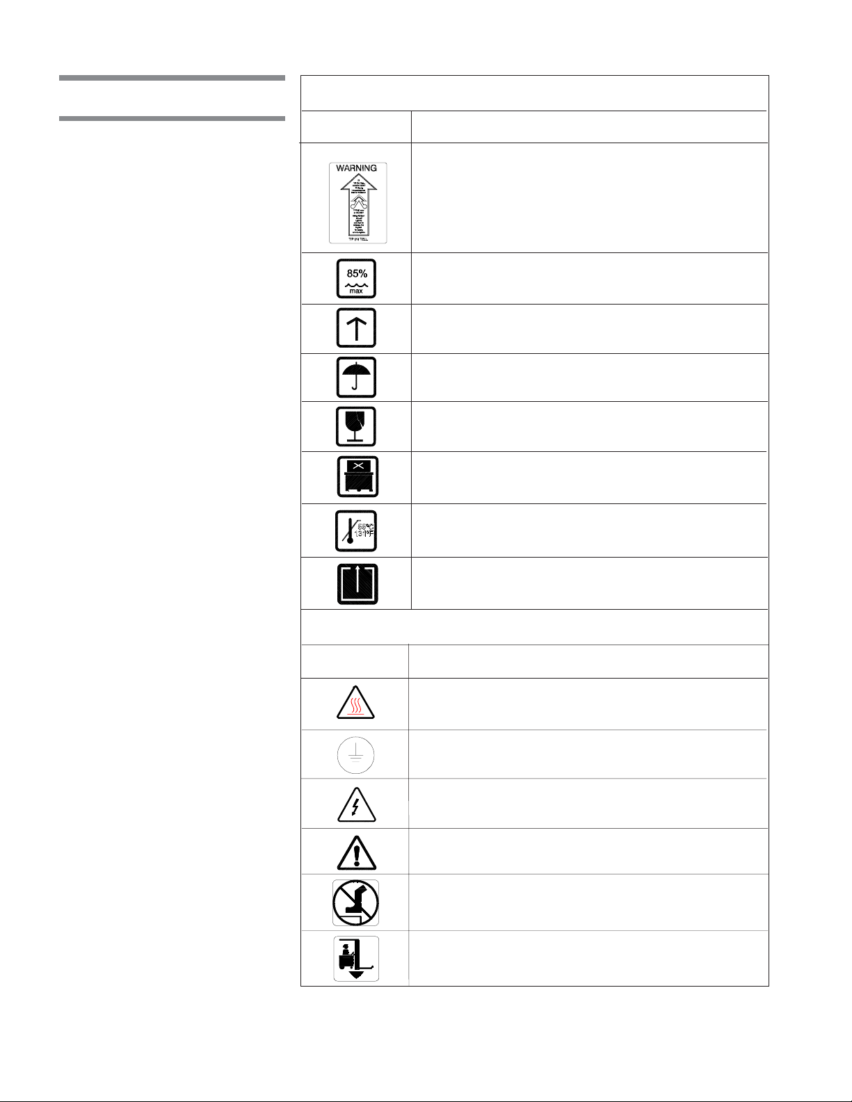
Symbols on the Crate:
Symbol Definition
TIP 'N TELL Indicator. "If TIP 'N TELL arrow point is
blue, this package has been on its side or tipped over
in transit. Make note on the bill of lading and check
for damage. Any claims for dripping on this notation.
Maximum Relative Humidity.
This Side Up.
Keep Dry.
Fragile.
Do Not Stack.
Maximum Temperature.
Open This Side.
Symbols on the Unit:
Symbol Definition
Transfer of Heat, Hot Surface.
Protective Earth (Ground).
Warning! Risk of Electrical Shock.
Attention, Consult Manual for Further Instructions.
Warning! Do Not Step Here.
Fork Lift: Place Forks of the Fork Lift Here.
1-4
122998-049 Uncrating/Installation Instructions Listing of Warnings, Cautions, and Symbols
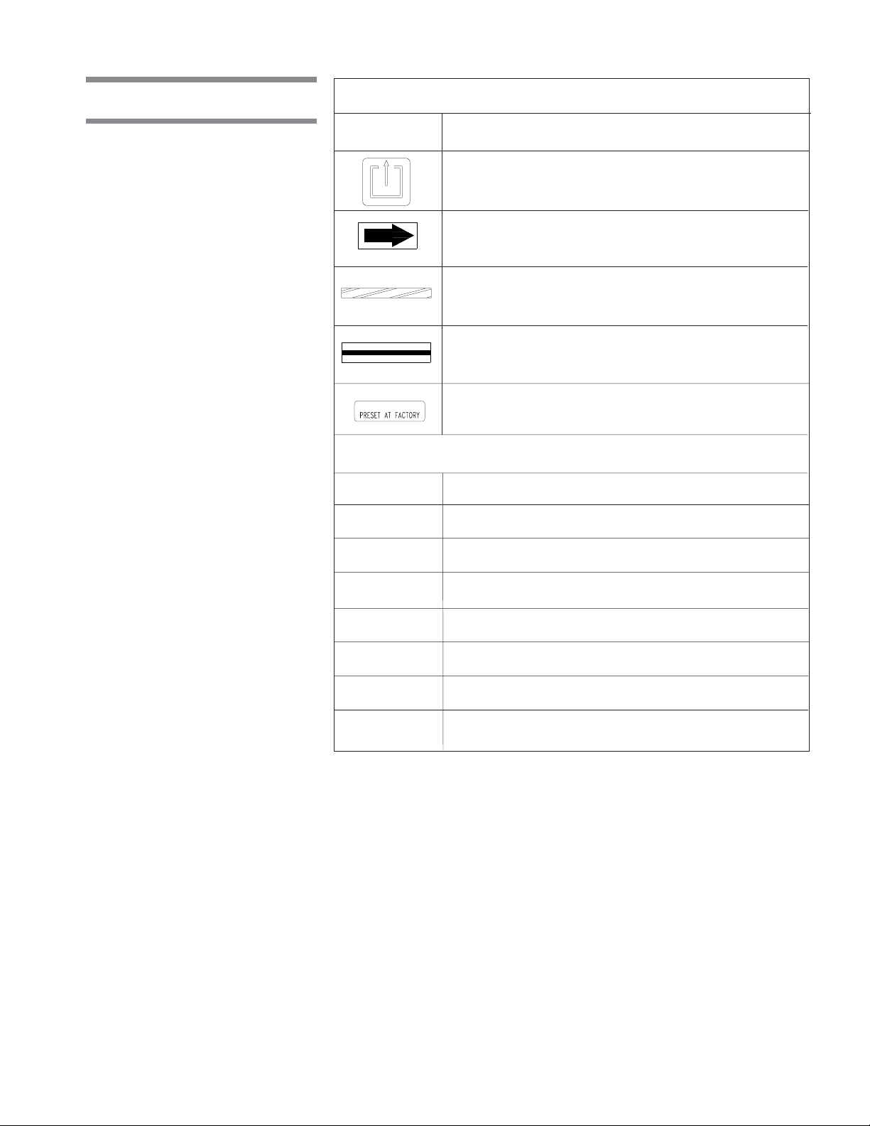
Symbols (cont'd)
Symbols on the Unit (cont'd):
Symbol Definition
Safety Exit: Push Here in Case of Emergency.
Rotation: Direction of the Rotation Device.
Emergency Stop Guard Rails: Push to Stop Washer
and De-energize Control.
Load Delimitation: Do not Place Load Over Marks.
Factory Adjustment: Do Not Adjust.
Information on the Nameplate:
Symbol Definition
MOD. Model Number of the Unit
SER. Serial Number of the Unit
kW Power Rating of the Unit.
VOLTS Voltage Rating of the Unit.
AMPS Amperage Rating of the Unit.
PH/Hz Phase/Hertz — Frequency of the Unit.
YEAR Year of Manufacturing of the Unit.
Listing of Warnings, Cautions, and Symbols Uncrating/Installation Instructions 122998-049
1-5

This Page Intentionally Left Blank
1-6
122998-049 Uncrating/Installation Instructions Listing of Warnings, Cautions, and Symbols
SITE PREPARATION
1. Review permissible environmental conditions: This washer is designed to
2.1 Before Installing
Equipment
give optimal results in an environment where maximum relative humidity is
less than 85% and maximum operating temperature is 104°F (40°C).
2. An optional seismic anchorage system is available for high risk seismic
zones.
3. Review installation requirements:
a. Clearance - Clearance space shown on Equipment Drawing is neces-
b. Barrier wall flange(s) installation - Refer to Equipment Drawing 122998-
c. Utility service lines:
2
sary for easy installation and proper operation and maintenance of
washer (see Equipment Drawing 122998-061).
061 for installation.
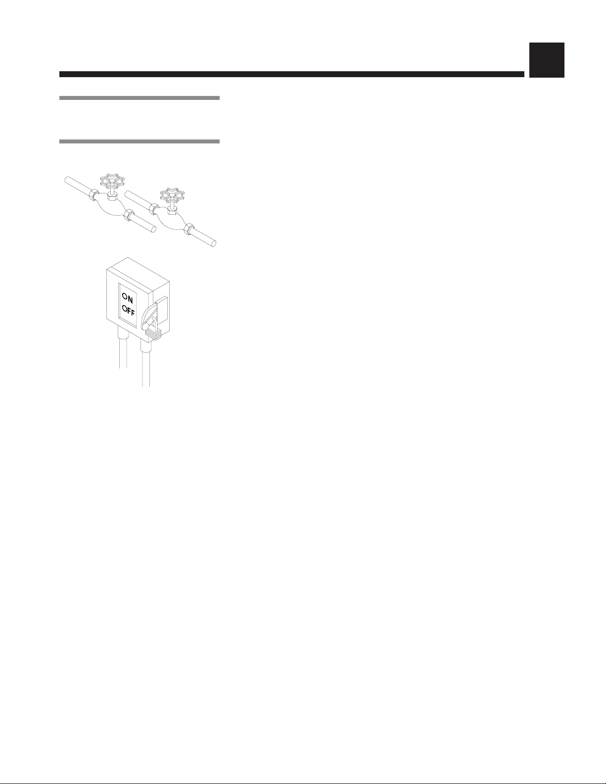
• To allow service on unit without shutting off building supply lines, shutoff
valves (not by STERIS) should be installed on steam, air and water lines
to unit (see Figure 2-1). Shutoff valves must be capable of being locked
in OFF position only.
• Disconnect switch (not by STERIS) must be installed on electric supply
line (see Figure 2-1).
Figure 2-1. Utility Service
Connections
• Disconnect switches must be marked as the disconnecting device for
the equipment and must be capable of being locked in OFF position
only.
• If machine is installed next to other equipment, shutoff valves and
disconnect switches should be located so that service can be shut off
to one piece of equipment at a time.
• The disconnect device of the equipment must be within easy reach of the
operator (preferably no more than 3 feet [1 m] away from equipment).
• Utility service requirements are shown on Equipment Drawing.
d. Electricity:
• Unit requires either 208 V, 60 Hz, 3-phase, 3-wire; 380/400/415 V,
50 Hz, 3-phase, 3-wire; or 480 V, 60 Hz, 3-phase, 3-wire power.
For 208 V, 60 Hz, a 50 A disconnect switch and AWG #6 (16 mm) wire
is recommended.
For 480 V, 60 Hz, a 30 A disconnect switch and AWG #10 (6 mm) wire
is recommended.
For 380/400/415 V, 50 Hz, a 20 A disconnect switch and AWG #12
2
(4 mm
If electrical supply is 380 V or 400 V, locate the 1000 VA transformer,
inside the main electrical box, and connect red wire of primary side to
380 V (H2) tap connection.
) wire is recommended.
2-1
Site Preparation Uncrating/Installation Instructions 122998-049

• Check Equipment Drawing or Identification nameplate (located on
frame of mobile mechanical core, above main electrical box, (see Figure
3-2) for proper voltage and amperage.
• This unit is overvoltage (Installation Category II).
• This equipment is not intended to be connected close to the main supply
of the building.
• This equipment needs to be installed according to local electrical codes.
4. This is a Class 1 equipment
A protective conductor connection is essential for the safe operation of the
equipment. Check for presence of protective conductor at equipment terminal
and verify if connection is well secured inside terminal with proper torque
requirement.
• Torque requirement for supply conductor terminals:
(L1-L2-L3): 0.89 -1.03 lb/ft (1,2 - 1,4 N•m)
• Protective conductor terminal:
16.96 - 29.50 lb/ft (23 - 40 N•m)
5. Make sure washer is placed, as shown on Equipment Drawing, in correct
relation to building supply lines. If unit is not at installation site, refer to
Section 3 for proper moving instructions.
6. If washer is pit-mounted:
• Pit must be clean.
• Pit drain piping should be level with pit floor to allow water to drain.
2-2
122998-049 Uncrating/Installation Instructions Site Preparation
UNCRATING/INSTALLATION INSTRUCTIONS
NOTE: Use a forklift to move crates.
3.1 Open Crates
NOTE: Uncrate on level floor as close to installation site as possible.
3
3.1.1 Assembled Unit
WARNING– PERSONAL INJURY AND/OR EQUIPMENT
DAMAGE HAZARD: When
moving the unit, use a forklift.
WARNING – LACERATION /
EYE INJURY HAZARD:
When removing bands, wear
gloves and eye protection,
and always use a tool specifically designed to cut the
bands. The bands used to
secure these crates can
cause personal injury when
cut and tension is released.
IMPORTANT
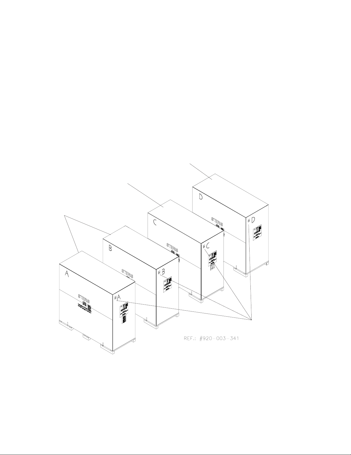
A fully equipped, assembled unit should consist of two or more crates:
• Crate A: Sump, floor, roof, non-service side panels, hardware box, control
panel(s), doors;
Dimensions: 89" W x 117" H x 109" L (2260 x 2972 x 2769 mm);
Max. Weight: 4000 lb (1818 kg).
• Crate C: Mechanical core;
Dimensions: 49" W x 85" H x 108" L (1245 x 2159 x 2743 mm);
Max. Weight: 2000 lb (909 kg).
• Crate D: Drying package (option) and/or enclosure wall option and/or
ramp (option):
Dimensions: 48" W x 44" H x 60" L (1229 x 1118 x 1524 mm).
Max. weight: 550 lb (250 kg).
NOTE: There is no Crate B for assembled units.
1. Bring washer as close as possible to installation site.
2. Position unit to open wooden crate from top and side. Provide a clear work
area on all sides.
3. Remove transparent plastic wrap from around crate.
4. Check Tip Indicator, located on upper left side of crates (see Figure 1). Tip
Indicator contains a blue compound at the bottom of the indicator. If unit has
been tipped, residue from the blue compound will be found higher up in the
indicator. If unit has been tipped, notify your STERIS regional office. A
service technician will review the equipment and determine if unit was
damaged.
::
: Bring in and uncrate only one crate at a time (see Figure 3-1).
::
5. Remove wood panels from top and sides of washer.
6. With skid under washer, lift and bring washer close to installation site.
7. Lift washer and remove skid from under washer.
8. Place washer into pit at final installation site. See Equipment Drawing (122998-061) and seismic anchorage report if option applies (122-997-987) for
proper installation.
IMPORTANT: Be sure that suction piping is located on service side.
9. Floor mounted units:
• Use a 24" spirit level, level sump, end-to-end and side-to-side, to adjust
the four leveling legs (one at each corner of sump).
• Distance from door sill and floor can be adjusted between 7" and 9" (18
cm to 23 cm).
• Make sure washer is flush with floor.
3-1
Uncrating/Installation Instructions Uncrating/Installation Instructionsl 122998-049
Basil 9500 Cage and Rack Washer
Drying Option
Mechanical Core
Tip Indicators
Figure 3-1. Crates
3-2
122998-049 Uncrating/Installation Instructions Uncrating/Installation Instructions

10. Pit-mounted units:
• Use a 24”spirit level, level sump, end-to-end and side-to-side, to adjust
four leveling legs (one at each corner of sump).
• To access leveling legs, external cabinet corners and front service panels
may have to be removed:
a) Remove screws holding front service panel in place, and remove panel.
b) Remove screws holding non-control side external cabinetcorner
panel in place and remove panel.
NOTE: leveling legs on control side panels can be reached from behind control
side panel without having to be removed.
11. Inside wash chamber: Cut bands and remove control(s) from bottom of
wash chamber.
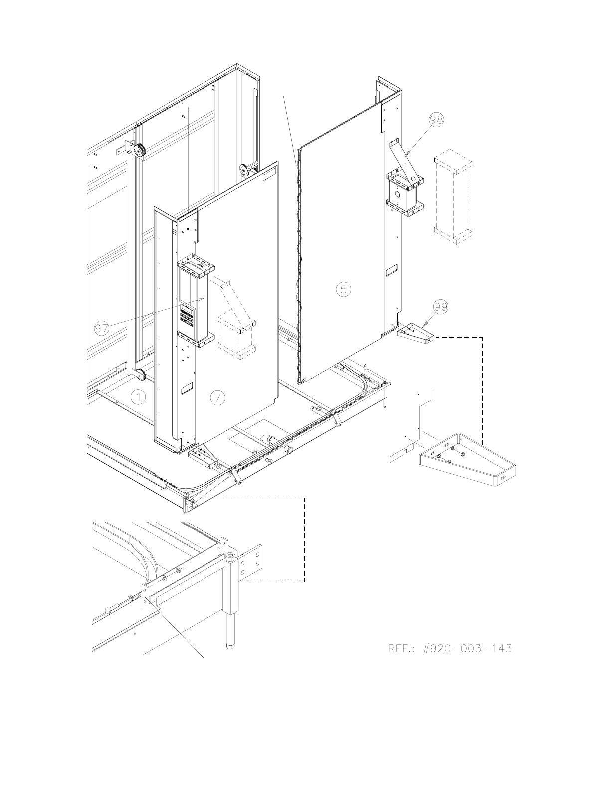
12. Install controls on service side cabinet corner (5, 7) using hardware
provided on controls (97, 98), tighten all hardware (see Figure 3-4).
NOTE: Always verify with customer if the location of main control with printer
corresponds to configuration required.
NOTE: Control Configuration. If controls have been changed from one end to
the other, align control with control door window as follows:
1. Close locks on control door.
2. Place control next to transparent membrane as if to operate control touch
pad.
3. Align control with control door window.
4. Tighten nuts.
5. Use Blank Sticker to cover printer window on secondary control side (see
Figure 3-14, detail "A").
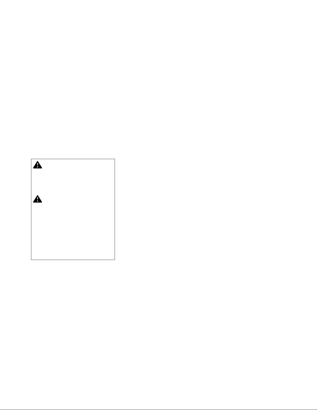
• Remove bolts holding pieces of wood securing spray headers in place.
• Remove bolts and remove wooden floor frame inside wash chamber.
• Remove pieces of wood securing doors in place.
Once unit is in place, see Section 3.2.25 (Crate C) and Section 3.3.5 (Crate D)
to complete washer installation.
3-3
Uncrating/Installation Instructions Uncrating/Installation Instructionsl 122998-049
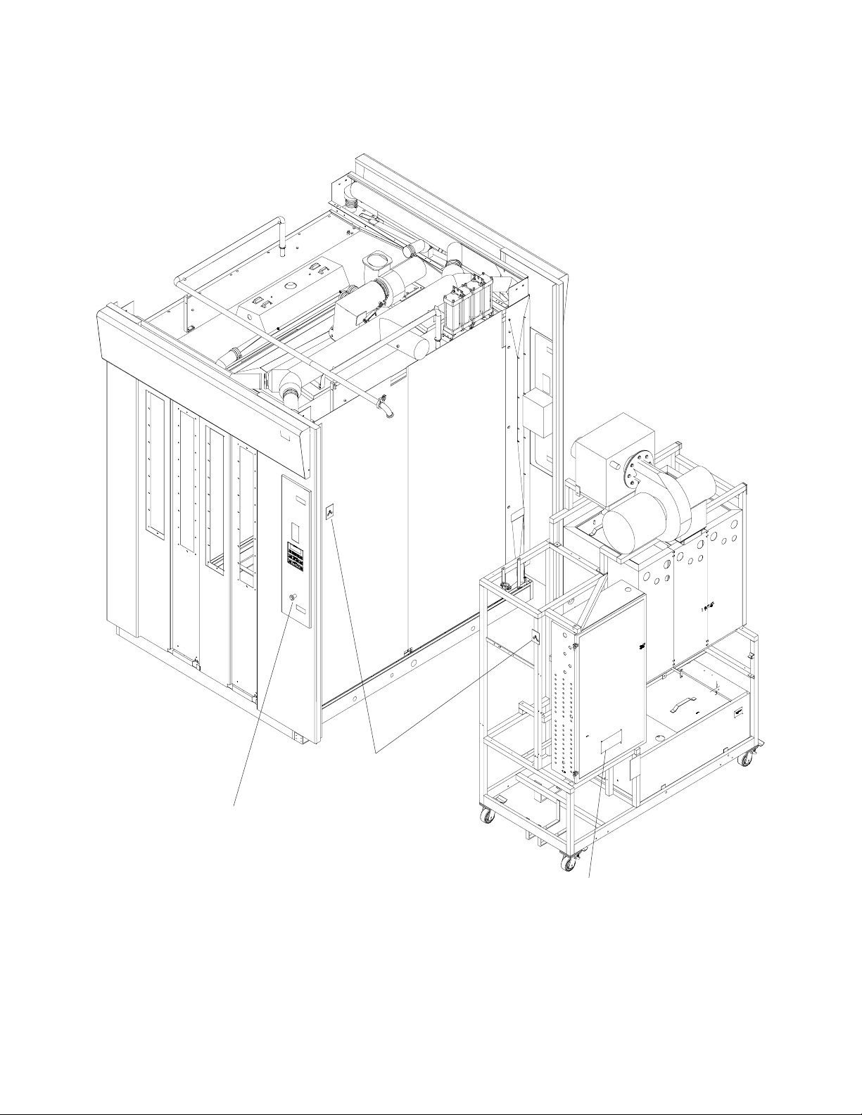
Non-Service Side
Right Side
Mechanical Core
Left Side
Tip Indicators
Emergency Stop Pushbutton
Service Side
Ref.: 920-003-135
Nameplate
Figure 3-2. Basil® 9500 Cage and Rack Washer, Reference View Point for All
Installation Locations
3-4
122998-049 Uncrating/Installation Instructions Uncrating/Installation Instructions
3.1.2 Disassembled Unit
A fully equipped, disassembled unit should consist of four crates:
• Crate A: Sump, floor, roof, non-service side panels, hardware box;
Dimensions: 49" W x 85" H x 108" L x (1245 x 2159 x 22743 mm);
Max. weight: 2000 lb (909 kg).
• Crate B: End roof, piping, guards, doors;
Dimensions: 49" W x 85" H x 108" L x (1245 x 2159 x 22743 mm);
Max. weight: 2000 lb (909 kg);
If option side panel add 200 lb (91 kg).
• Crate C: Mechanical core;
Dimensions: 49" W x 85" H x 108" L x (1245 x 2159 x 22743 mm);
Max. weight: 2000 lb (909 kg).
• Crate D: Drying package (option);
Dimensions: 48" W x 44" H x 60" L x (1229 x 1118 x 1524 mm);
Weight: 550 lb (250 kg);
and/or enclosure wall option, Weight: 700 lb (317 kg);
and/or ramp (option);
Weight: 550 lb (250 kg).
WARNING– PERSONAL INJURY AND/OR EQUIPMENT
DAMAGE HAZARD: When
moving the unit, use a forklift.
WARNING – LACERATION /
EYE INJURY HAZARD:
When removing bands, wear
gloves and eye protection,
and always use a tool specifically designed to cut the
bands. The bands used to
secure these crates can
cause personal injury when
cut and tension is released.
1. Remove transparent plastic wrap from around crate.
2. Check Tip Indicator, located on upper left side of crates (see Figure 3-1). Tip
indicator contains a blue compound at the bottom of the indicator. If unit has
been tipped, residue from the blue compound will be found higher up in the
indicator. If unit has been tipped, notify your STERIS regional office. A
service technician will review the equipment and determine if unit was
damaged.
3. Position wooden crate to enable opening from top and side. Provide a clear
work area on all sides.
4. Remove and discard side wooden panels.
IMPORTANT
::
: Do not remove wooden top and side crate frames. All parts must
::
be removed from crate ends. Do not remove parts from top of crates.
NOTE: Do not remove white protective adhesive paper until after utilities are
connected.
5. Mobile mechanical core:
• Check Tip Indicator, located on frame below main electrical box (see
Figure 3-2). If unit has been tipped, notify your STERIS regional office. A
service technician will review the equipment and determine if unit was
damaged.
6. Repeat steps 1 through 3 for each crate.
IMPORTANT
::
: Become familiar with components and installation instructions
::
before installing washer. (see Fig. 3-2).
3-5
Uncrating/Installation Instructions Uncrating/Installation Instructionsl 122998-049
1" [25 mm] Min. Clearance
94" [2,39 m] Pit
92" [2,34 m] Washer
3" [77 mm] Min. Clearance
6" [152 mm] Min.
Suction Piping
Mechanical Core
1" [25 mm] Min.
68-3/4" [1,75 m] Washer
78" [1,98 m] Pit
Mechanical Core
Washer Outline
Figure 3-3. Pit Mounted Unit
3-6
122998-049 Uncrating/Installation Instructions Uncrating/Installation Instructions
3.2 Disassembled Unit Assembly
IMPORTANT: Uncrate and assemble only one crate at a time.
NOTE: Major components in crate are numbred to assist in inventory and
assembly of unit. Review crate contents by matching numbers on components
to numbers listed in parenthesis ( ) and on figures.
NOTE: Bolts, washers, nuts, and other items needed for the assembly of the unit
are in a box labeled HARDWARE, inside Crate A.
3.2.1 Crate A
3.2.2 Sump
Contents:
• Sump, without floor and floor grating assembly (1).
• Cabinet corner panels, non-service side, left (2) and right (4).
• Cabinet corner panels, service side, left (7) and right (5).
• Roof mounting brackets (9).
• Non service side roof (10) and service side roof (11).
• Floor frame (31).
• Floor grating sections: 1 central section (32) 2 side sections (33).
• Main Control (97).
• Remote Control (98).
• Cabinet supports (99).
• Hardware Installation Kit: bolts, silicon, etc.
Figure 3-3
1. See Equipment Drawing (122998-061) and seismic anchorage report if
option applies, (122997-987) for complete installation details.
NOTE: For seismic installation, refer to Seismic Anchorage Instructions (included with documentation).
2. Install sump (1) on floor or in pit (if pit-mounted unit).
IMPORTANT
WARNING – PERSONAL INJURY AND/OR EQUIPMENT
DAMAGE HAZARD: When
moving the unit, use a forklift.
WARNING– LACERATION
HAZARD: When removing
bolts, wear gloves to potect
your hands.
Uncrating/Installation Instructions Uncrating/Installation Instructionsl 122998-049
3. Floor mounted units:
• Use a 24” spirit level, level sump, end-to-end and side-to-side, to adjust
four leveling legs (one at each corner of sump).
• Distance from door sill and floor can be adjusted between 7 and 9 inches
(18 cm to 23 cm).
4. Pit-mounted units:
• Make sure that no floor covering materials, such as tile or wood, will be
installed after unit is into pit. If a floor covering is required, make sure unit
is flush with floor covering.
• Use a 24” spirit level, level sump, end-to-end and side-to-side, to adjust
four leveling legs (one at each corner of sump).
• Make sure washer is flush with floor.
5. Floor Gratings:
a) Install floor frame (31) inserting pins in holes (non-service side).
b) Install floor gratings (center (32), sides (33) ) on floor frame.
: :
: Be sure that suction piping is located on service side.
: :
3-7
Apply Silicone
Apply Silicone
Detail C
Wall
Detail A
Angle Bracket
Detail B
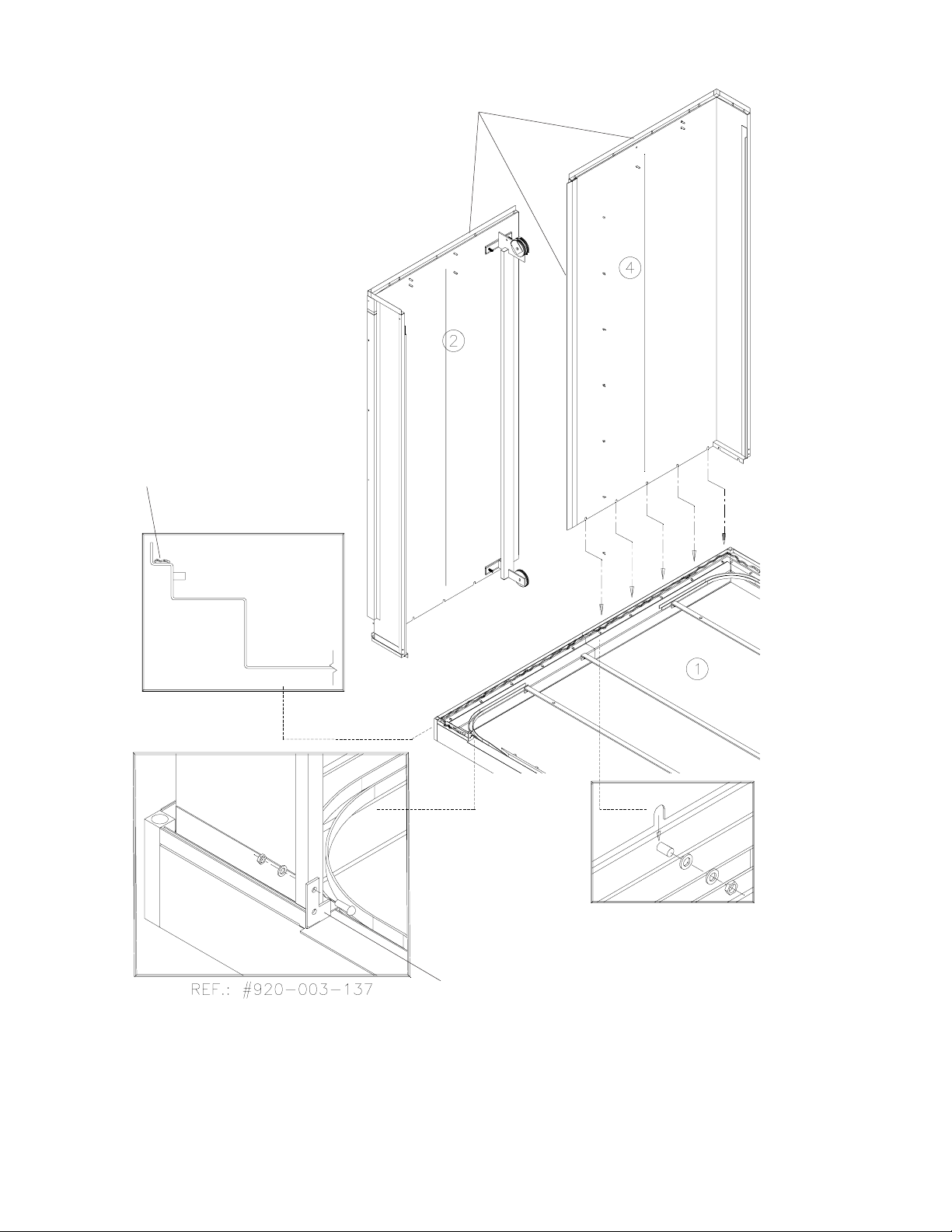
Figure 3-4. Non-Service Side Walls
3-8
122998-049 Uncrating/Installation Instructions Uncrating/Installation Instructions

3.2.3 Non-Service Side Walls
Figure 3-4
IMPORTANT
1. Spread a 3/8 inch (11 mm) bead of silicone on non-service side sump base
(1).
2. Spread a 3/8 inch (11 mm) bead of silicone on top and side of left corner
panel (2).
NOTE: For washer installation with no clearance on non-service side of wash
cabinet, bolt non-service side panels together (step 6), before bringing panels
close to the washer.
3. Bring left corner panel (2) using installation cutout handles. Seat over sump,
behind angle brackets (see Detail B).
NOTE: Finger-tighten the 1/4 - 20 bolts first to support the panel.
4. Finger-tighten hardware holding corner panels to sump, use 5/16 washers,
5/16 spring washers, and nuts at bottom of sump (see Detail A). Use 1/4 20 x 3/4 bolts, 1/4 lockwashers, and 1/4-20 nuts for angle brackets (see
Detail B).
5. Repeat steps 2 through 4 to install right non-service corner panels (4).
6. From outside, on non-service side, fix non-service side panels together,
using four 5/16-18 x3/4 bolts, eight 5/16 washers, and four 5/16 lockwashers
provided.
::
: Two people minimum are required to assemble side walls.
::
7. Tighten wall to sump and secure wall to angle brackets (see Detail B).
8. Spread a 3/8 inch (11 mm) bead of silicone on central joint of panel (see
Detail C).
3-9
Uncrating/Installation Instructions Uncrating/Installation Instructionsl 122998-049
Apply Silicone
Angle Bracket
Detail A
Figure 3-5. Service Side Panels
3-10
122998-049 Uncrating/Installation Instructions Uncrating/Installation Instructions

3.2.4 Service Side Panels
Figures 3-4 and 3-5
3.2.5 Control
Configuration
IMPORTANT
1. Apply a 3/8 inch (11 mm) bead of silicone on service side sump base (1).
2. Apply a 3/8 inch (11 mm) bead of silicone on side of right corner panels (5).
3. Bring right corner service side panel (5) and seat over sump, behind angle
brackets (see Figure 3-4, Detail A).
::
: Two people minimum are required to assemble side walls.
::
NOTE: Finger-tighten the 1/4-20 bolts first to support the panel.
4. Finger-tighten hardware holding corner panels to sump. Use 5/16 washers,
5/16 springwashers and nuts at bottom of sump (see Figure 3-4, Detail A).
Use 1/4 - 20 x 3/4 bolts, 1/4 lockwashers, and 1/4-20 nuts for angle brackets
(see Figure 3-4 Detail B).
5. Repeat steps 2 through 4 to install left corner service side (6).
6. From outside, on service side, fix service side panels together, using four
5/16-18 x 3/4 bolts, eight 5/16 washers, four 5/16 lockwashers, and nuts
provided.
7. Tighten wall to sump and secure wall to angle brackets.
Single door units:Single door units:
Single door units:
Single door units:Single door units:
Install Main Control (97) on unit, using 1/4 washers and 1/4-20 nuts
provided. Make final adjustment when installing cabinet and tighten
hardware (39, or 40) (See Figure 3-4 and 3-11).
Double door units:
NOTE: Controls can be installed to suit customer requirements.
Factory installation: Main Control, (97) is installed to the right and remote
control (98) is installed to the left (operator facing service side of unit).
1. To change printer location, dismantle both support with controls, (controls
should stay on supports) (see Figure 3-5) and re-install on opposite ends
of washer, using 1/4 washers and 1/4-20 nuts provided.
2. Install control cabinet supports (99), one bottom right and one bottom left
corner, using 1/4 washers and 1/4-20 nuts provided. Make final adjustments when installing cabinet (39, 40) and tghten hardware (see Figure
3-14).
3-11
Uncrating/Installation Instructions Uncrating/Installation Instructionsl 122998-049
Studs
Figure 3-6. Temporary Roof Support
3-12
122998-049 Uncrating/Installation Instructions Uncrating/Installation Instructions

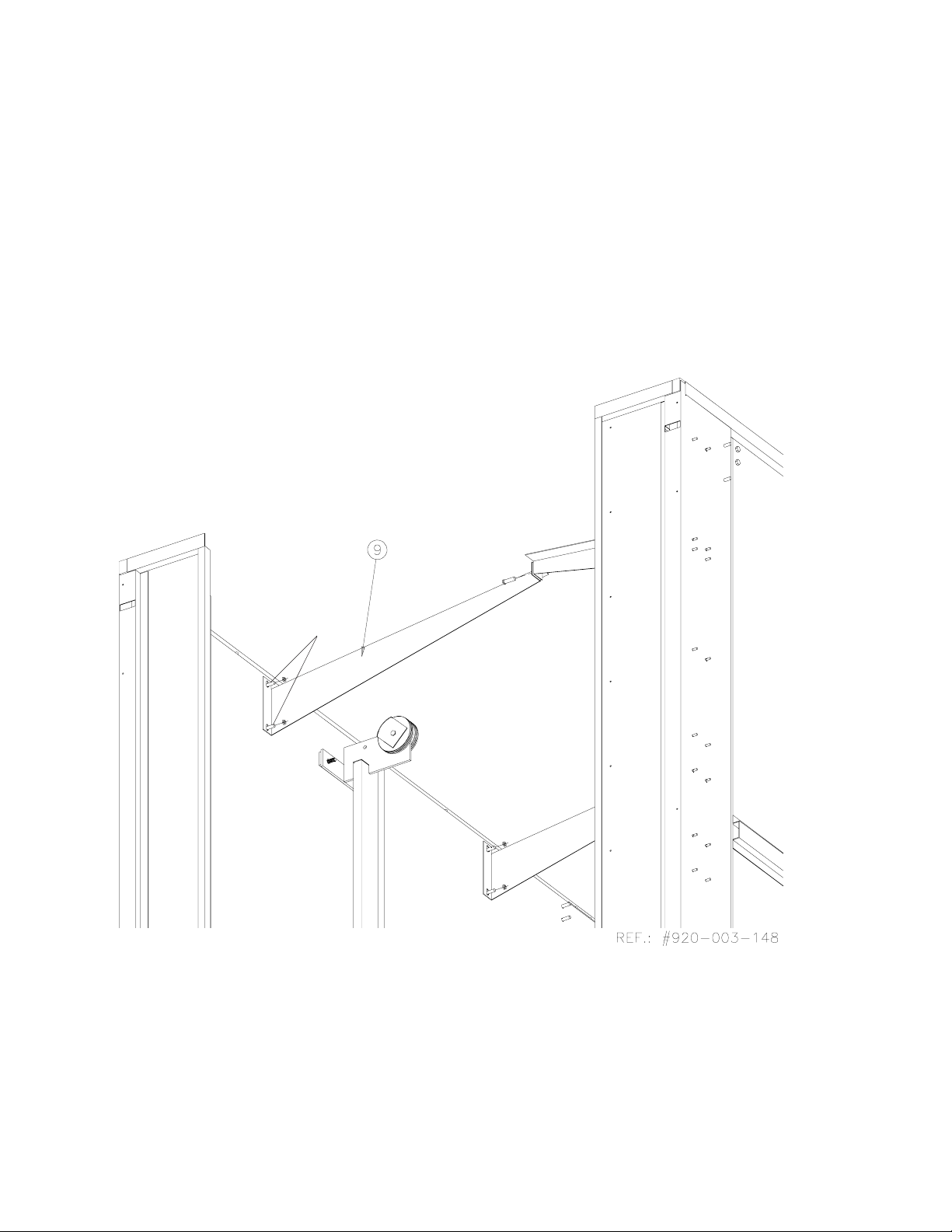
3.2.6 Temporary Roof Support
Figure 3-6
1. On each side of washer, install temporary roof mounting supports (9).
Position supports so they are in the highest position. Bolt temporary roof
mounting supports to wall, using 5/16-18 nuts and 5/16 washers provided.
2. Bolt supports together in the middle with 5/16 -18 x 3/4 bolts, 5/16 washers
and 5/16 nuts.
3-13
Uncrating/Installation Instructions Uncrating/Installation Instructionsl 122998-049
Detail A
Roof, apply Silicone
Side Wall Stud
Apply
Silicone
Figure 3-7. Roof
3-14
122998-049 Uncrating/Installation Instructions Uncrating/Installation Instructions

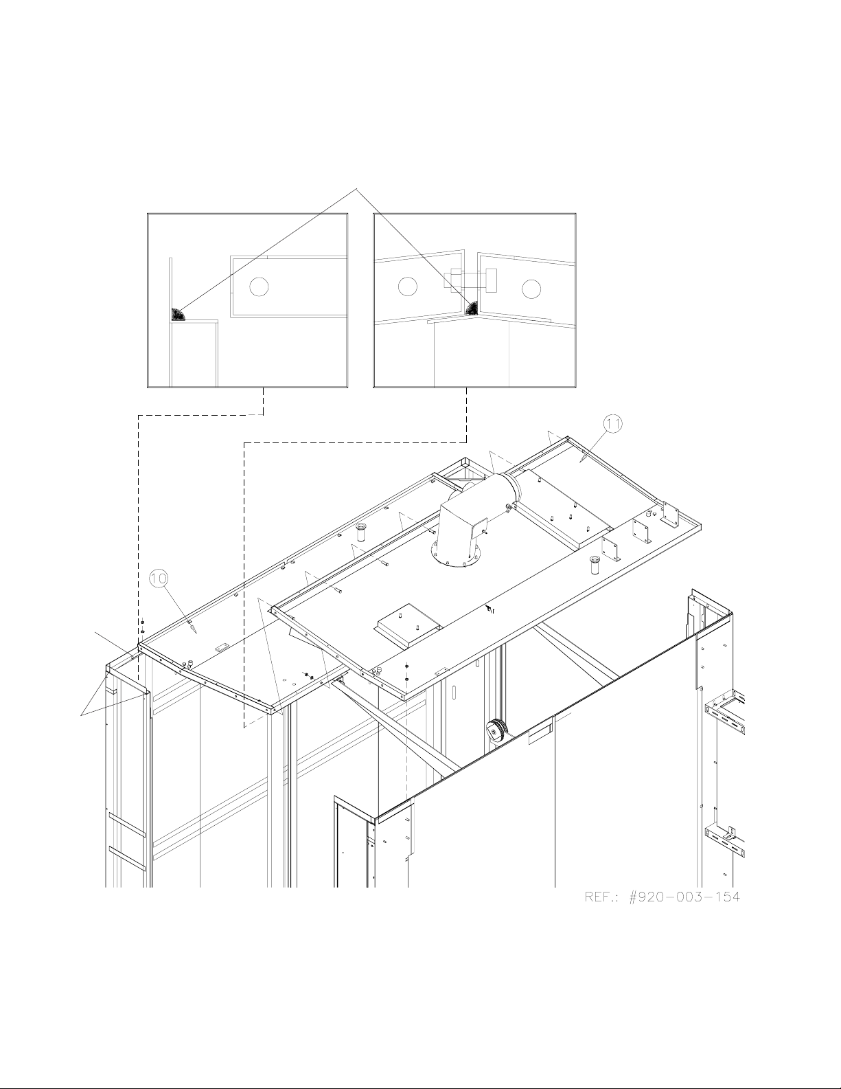
3.2.7 Roof
Figure 3-7
IMPORTANT: Installation of roof must be completed within 45 minutes
maximum, before silicone starts to dry.
NOTE: Refer to Equipment Drawing 122998-061 for clearance.
1. Apply a 3/8 inch (11 mm) bead of silicone along the corner of side panels,
non-service and service side (see Detail A).
2. Slide non-service side roof (10) over temporary mounting supports aligning
holes and studs.
3. Apply a 3/8 inch (11 mm) bead of silicone on edge of service side roof panel
(see Detail A).
4. Slide service-side roof (11) over temporary mounting supports.
IMPORTANT: Do not tighten nuts yet.
5. Assemble roof sections, using 5/16-18 x 3/4" bolts, 5/16-18 washers, 5/1618 lockwashers and 5/16-18 nuts provided.
6. Bolt roof sections to side wall studs, using 5/16-18 nuts, 5/16 washers, and
5/16-18 lockwashers provided. Do not tighten.
3-15
Uncrating/Installation Instructions Uncrating/Installation Instructionsl 122998-049

This Page Intentionally Left Blank
3-16
122998-049 Uncrating/Installation Instructions Uncrating/Installation Instructions

3.2.8 Crate B
Contents:
• Two Roof End Sections (pre-assembled), Left (12) and Right (13).
• Door Rails Supports, two for single door units (41, 42), four for double door
units (43, 44).
• Exterior Stainless Steel Jacket Panels, non-service side (14,15) (Option).
• Exhaust Fan (17) (option).
• Oil Tanks, left (18), right (16).
• Main Air Duct (19) (option, drying).
• Four Secondary Drying Ducts (20, 21, 22, 23) (option).
• Two Air Exhaust Ducts (24, 25).
• Two Spray Header Inlet Piping (26 long, 27 short).
• Traveler System Assembly (28).
• Guard Rails, Non-service side (29), and Service side (30).
• Spray Headers, Non-service side (35) and Service side (36).
• Cabinet Panel, Left non-service side (37).
• Cabinet Panel, Right non-service side (38).
• Cabinet Panel, Left service side (39).
• Cabinet Panel, Right service side (40).
• Door Frames,(45) and (46); If double door unit: Door Frames, (47) and (48).
• Door Panels (45 a) (45 b) and (46 a) (46 b); If double door unit: (47 a) (47 b)
(48 a ) and (48 b).
• Roller Guide (52).
• Spray Header Guide (49) (53).
• Roof Stoppers (54).
• Ventilation Duct Assembly (with gaskets) (55).
• Pulley Guards (56).
• Single Door Panels (option) (57), cover plates (63).
• Traveler System Driver Cable (66).
• Traveler System Safety Cable (67).
• Front Service Panels (76) (77) (if double door unit).
• Temporary Roof End Mounting Bracket (86).
• Transition Plate (91) (92) (Option).
• Transition Plate Support (93) (94) (95) (Option).
3-17
Uncrating/Installation Instructions Uncrating/Installation Instructionsl 122998-049

Apply Silicone
DETAIL A
Door Guide
Support Angle
Figure 3-8. Roof End
3-18
122998-049 Uncrating/Installation Instructions Uncrating/Installation Instructions

3.2.9 Roof End
Figure 3-8
1. Spread a 3/8 inch (11 mm) bead of silicone on edge of roof.
WARNING – PERSONAL INJURY HAZARD: Two people
are required to install the
roof end sections. Using a
step ladder, first set roof end
on temporary roof end support brackets, then lift up
and sit into position.
2. On (both) side(s) of washer (for a double door unit), install Temporary Roof
End mounting brackets (86). Position brackets so they are in the highest
position.
3. Lift left-end roof section (12) and place on temporary roof end support
brackets (86). Lift over edge of roof and sit into position. Align holes and
studs. Bolt into place.
4. Repeat steps 1 through 3 for right-end section (13).
5. On each end, bolt roof end sections to roof using 5/16-18 x 3/4 bolts, 5/16
washers, and 5/16 lockwashers provided. Do not tighten yet.
6. Bolt roof ends on side wall panel corner studs using 5/16 washers, 5/16
lockwashers, and 5/16-18 nuts.
7. Remove temporary roof end mounting brackets (9).
8. Tighten all nuts on top of unit (center and edges of roof panels).
9. From inside washer, screw drying ducts to roof.
3-19
Uncrating/Installation Instructions Uncrating/Installation Instructionsl 122998-049

Guide Rail Holder
Studs
Door Rail Holder
Rail Holder Angle
Door Rail
Fix to End Roof Fold
Figure 3-9. Door Rail Holders
3-20
122998-049 Uncrating/Installation Instructions Uncrating/Installation Instructions

3.2.10 Door Rail Holders
Figure 3-9
1. Install door rail supports (41, 42, 43, 44) on interior cabinet walls and roof,
using 5/16-18 nuts, 5/16 washers, 5/16 lockwashers, and 5/16 nuts (see
Figure 3-8, Detail A).
2. Install door rails (two on single units, four on double-door units) on door
guide support angles using setscrews.
3. Opposite end of rails should sit on end roof fold. Bolt rails to end roof fold
using 1/4-20 x 3/4 nuts and lockwashers.
4. Tighten roof and door guide assemblies in the following order: bolts on top
of roof, bolts on guide rail holders.
3-21
Uncrating/Installation Instructions Uncrating/Installation Instructionsl 122998-049

Detail A
Figure 3-9. Roof Components
3-22
122998-049 Uncrating/Installation Instructions Uncrating/Installation Instructions

3.2.12 Roof Components
Figure 3-10
1. On service side, install main drying manifold (19) (option) on roof, fingertighten 5/16 washers, 5/16 lockwashers, and 5/16-18 nuts.
2. Install exhaust fan (17) (option) on service-side roof using 5/16-18 x 3/4 bolts,
5/16 lockwashers, 5/16 washers, 5/16 nuts and pre-assembled collar and
gaskets on damper.
3. Install roof piping with supports (26) on non-service side and (27) on service
side, using 1/4 spring washers, 1/4 washers, and 1/4-2 0 x 1 / 2 bolts.
4. Install secondary drying manifolds (20, 21, 22, 23), using clamps and gaskets
already installed on manifolds.
5. Install damper suction piping (24, 25) using collar and gaskets already
installed.
6. Install oil tanks (16) (single door unit) or (16 and 18) (double door units) and
bolt into place using 5/16-18 x 1 bolts, 5/16 washers, 5/16 lockwashers and
5/16-18 nuts (see Detail A).
7. Tighten hardware.
8. Install traveler drive mechanism (28) on service side wall using studs welded
to walls to fix supports. Use 3/8 washers, 3/8 lockwashers and 3/8-16 nuts
provided.
3-23
Uncrating/Installation Instructions Uncrating/Installation Instructionsl 122998-049

Apply Silicone
Apply Silicone
Apply Silicone
Apply Silicone
Figure 3-11. Single-Door Washer Back Panel (Option)
3-24
122998-049 Uncrating/Installation Instructions Uncrating/Installation Instructions

3.2.13 Single-Door Washer
Back Panel Installation
(option)
Figure 3-11
IMPORTANT: For single door units, install Back Panel before installing
Emergency Guard Rails.
1. Apply silicone on cabinet corners and on door frames.
2. Secure back panel (57) to side walls using 10 - 32 x 1/2 screws, 3/16
washers, and 3/16 lockwashers provided.
3. Remove nut from corner (see Figure 3-17).
4. Apply silicone on upper corner panels.
5. Install cover plates (63) on top of right and left cabinet corners.
3-25
Uncrating/Installation Instructions Uncrating/Installation Instructionsl 122998-049

Detail A
Microswitch Actuator
Top Guard Rails
Installation
Stud
Emergency Guard
Rail
Rod
Roof
Hole
Detail B
Roof Connection
Gasket
Plastic Support
Bottom Guard Rails
Assembly
Detail C
Figgure 3-12. Crate D: Inside Chamber Components
3-26
122998-049 Uncrating/Installation Instructions Uncrating/Installation Instructions

3.2.14 Emergency Guard Rails
Figure 3-12
IMPORTANT: For single door units, Back Panel must be installed before
installing Emergency Guard Rails. Refer toSection 3.2.13, “Single-Door Washer
Back Panel Installation."
1. Remove floor gratings and floor frame.
2. Remove nuts and microswitch actuator from end of guard rail (29, 30).
3. On non-service side, install guard rail (29). Insert top of rod into roof holes.
4. Fix guard rail frame to roof studs. Make sure gasket is inserted between roof
and top of guard rail frame. Finger-tighten 5/16 washers, 5/16 lockwashers,
and 5/16-18 nuts (see Detail A).
5. Finger-tighten hardware to fix bottom of guard rail frame to the floor frame
using two 5/16 -18 x 1 bolts, 5/16 lockwashers, and 5/16 flat washers
provided (Detail C).
6. Repeat steps 2 through 5 for service side guard rail.
7. Distance between the two guard rails (side to side) should be 46” (1.168 m).
Adjust if necessary. Tighten all hardware.
8. Lower guard rail.
9. On top of wash chamber, re-install nuts and actuator on guard rail rod. Raise
actuator until microswitch rod rests into actuator notch. Tighten three nuts
to fix actuator. The microswitch should “click” when raised.
10. From inside wash chamber raise guard rail.
11. On top of washer, check for proper adjustment of actuator. Microswitch
should move freely, without clicking, when guard rail is raised.
12. Re-install floor frame (31) and floor gratings (32, 33).
NOTE: Microswitch must be triggered when Emergency Guard Rail is raised.
3-27
Uncrating/Installation Instructions Uncrating/Installation Instructionsl 122998-049

Figure 3-13. Spray Headers
3-28
122998-049 Uncrating/Installation Instructions Uncrating/Installation Instructions

3.2.15 Spray Headers
Figures 3-12 and 3-13
1. On non-service side, install spray headers (35) on pre-assembled spray
header mechanism (see Figure 3-1,2 Detail B), using 1/4-20 x1/2 bolts
provided securing plate, 1/4 washers, and 1/4 lockwasher on mechanism.
2. Connect end of hoses to roof connections, using clamps and gaskets
provided. Prior to tightening clamps, twist hose towards cabinet approximately 1/2 turn. Tighten all clamps. Verify that hose is close to side wall.
Loosen and twist 1/2 turn until hose moves freely along the wall.
3. Install spray header guide (49) using 8-32 x 3/8 screw and 3/16 washer on
top: fix bottom of guide using 5/16 washer and 5/16 lock washer (see Figure
3-13).
NOTE: Make sure guide fold is inserted between the two plastic roller guides
fixed to spray header.
4. Repeat steps 1 and 2 for service side spray headers (36).
3-29
Uncrating/Installation Instructions Uncrating/Installation Instructionsl 122998-049

RIGHT SIDE
DETAIL A
Blank Sticker
Side Fixation
Figure 3-14. Cabinet Corners
Front
Fixation
LEFT SIDE
3-30
122998-049 Uncrating/Installation Instructions Uncrating/Installation Instructions

3.2.16 Cabinet Corners
Figure 3-14
NOTE: Match cabinet corner number to corresponding number on cabinet side.
1. Install cabinet control side panel (39 and/or 40) using two 1/4-20 x 3/4 bolts,
1/4 washers and lockwashers, 1/4-20 nuts, and two 10-32 x 3/8 screws.
2. Install cabinet non-control side panel (37 and/or 38), using 1/4 washers 1/4
lockwashers, and 1/4-20 nuts.
NOTE: For single door units with Exterior Stainless Steel Jacket option,
configuration will include corner panels: 37, 38, 39, 40.
3. Single door unit without Exterior Stainless Steel Jacket option:
• A set of panels (37 and 39 or 38 and 40) will be installed depending on
control side.
4. Double door unit configuration will include cabinet panels 37, 38, 39 and 40.
5. Non-service side cabinet option installation:
NOTE: View Point is from service side.
• Install exterior stainless steel jacket panel, non-service, right (14), using
10-32 x 1-1/4 screws and 3/16 washers.
• Install exterior stainless steel jacket panel, non-service, left (15) using 10-32
x 1/4 screws and 3/16 washers.
NOTE: For floor mounted units with Exterior Stainless Steel Jacket option,
install base covering panel on non-service side.
3.2.17 Control Panel Adjustment
Figure 3-14
NOTE: Control Configuration. If controls have been changed from one side to
the other, align control with control door window, as follows:
1. Close locks on control door.
2. Place control next to transparent membrane as if to operate control touch
pad (see Figure 3-14, Detail A).
3. Align control with door window.
4. Tighten nuts.
5. Use Blank Sticker to cover printer window on secondary control side.
NOTE: Control Configuration verification will be performed later in Section 5,
Start-Up Test.
3-31
Uncrating/Installation Instructions Uncrating/Installation Instructionsl 122998-049

Detail A
Detail B
Detail D
Detail C
Figure 3-15. Door Frames
3-32
122998-049 Uncrating/Installation Instructions Uncrating/Installation Instructions

3.2.18 Door Frames
Figure 3-15
1. Align top pulleys (see Detail A).
2. Install door frame (45) halfway into corner. Make sure bottom hinges are
aligned with door opening (see Detail B).
3. From inside unit, lift door frame placing bottom rollers into door rails (see
Detail C).
4. Lift door frame to install top rollers and adjust door frame (see Detail D).
5. Install door frame (46) following the same procedure.
6. On double door units, repeat steps 1 through 4 for door frames (47) and (48).
3-33
Uncrating/Installation Instructions Uncrating/Installation Instructionsl 122998-049

Detail A
Detail B
Detail C
Figure 3-16. Roller Stoppers
3-34
122998-049 Uncrating/Installation Instructions Uncrating/Installation Instructions

3.2.19 Roller Stoppers
Figure 3-16
1. Slide door frame inside washer.
2. Remove plastic tape from plastic blocks (see Figure 3-15, Detail B).
3. Place plastic blocks on both sides of pivoting arm.
4. Push and snap cover (52) onto plastic block and pivoting arm (see Detail A).
5. Finger tighten two (1/4-20 x 1/2) bolts, washers and lockwashers; and four
(10-32 3/4) screws in place (see Detail B).
6. Pry slightly to make sure cover is flush with top of pivoting arm (see Detail
C).
7. Tighten all bolts and screws.
8. Install roof stopper (54) on pulley support. Use 10/32 x1/2 screws (see
Figure 3-14).
9. Slide doors on rails and verify that pivots and pulleys slide freely. Make sure
stoppers slide under ventilation duct screws.
10. Repeat steps 1 through 5 for each door frame.
3-35
Uncrating/Installation Instructions Uncrating/Installation Instructionsl 122998-049

Detail C
Detail A
Ground Cables
Detail B
Figure 3-17. Door Panels
3-36
122998-049 Uncrating/Installation Instructions Uncrating/Installation Instructions

3.2.20 Door Panels
WARNING – ELECTRICAL
SHOCK HAZARD: Fasteners
and star washers are used
to ensure protective bonding continuity. Always reinstall any star washers
which may have been removed during installation or
servicing.
WARNING – PERSONAL INJURY AND/OR EQUIPMENT
DAMAGE HAZARD: Do not
remove protective paper
covering from front of doors
until installation is complete.
Paper secures exterior glass
in place during transport and
installation.
CAUTION– POSSIBLE
EQUIPMENT DAMAGE: Do
not remove adhesive tape
from corner spring traps
before installation of doors
is completed.
Figure 3-17
1. Install door panel (45 a). Align top and bottom bolts. Slightly lift door panel
to adjust into lower rod by pushing door panel slightly at the bottom.
Thighten bottom screw using a 3-32 allen hex key. Lock in upper position
(see detail A).
2. Install door panel 45 b following step 1.
3. Install ground cables (see Detail B).
4. To close door sections, fold left side panel into right side panel, then press
panels firmly into place (see Detail B).
NOTE: After installing corner spring trap guides remove adhesive paper from
spring trap.
5. On double door units, repeat steps for door panels 47 a, 47 b, 48 a and 48 b
(not shown).
NOTE: Do not remove white protective adhesive paper from window before
completing installation of doors.
IMPORTANT: After completing installation of doors, insert a screw driver
between door frame and door panels to pry doors downwards to make sure
doors are adjusted in place (see Detail C).
3-37
Uncrating/Installation Instructions Uncrating/Installation Instructionsl 122998-049

End Roof
Section
Detail A
Ventilation Duct
Alignment Bolts
Figure 3-18. Ventilation Duct
3-38
122998-049 Uncrating/Installation Instructions Uncrating/Installation Instructions

3.2.21 Ventilation Duct
Figure 3-18
1. Completely slide doors inside washer.
2. Install ventilation duct (55) inside wash chamber, matching holes on end
roof section (12), using 8/32 x 3/8 screws.
3. Slip duct gasket over door top baffle (see Figure 3-8).
IMPORTANT: Make sure that Ventilation Duct slides and fits between the three
alignment bolts and end roof section.
4. Repeat steps 1 through 3 on opposite end of washer.
5. Verify that doors open and close freely.
3-39
Uncrating/Installation Instructions Uncrating/Installation Instructionsl 122998-049

Ventilation Duct
Door Rail Holder
Fold
Figure 3-19. Pulley Guards
3-40
Uncrating/Installation Instructions Uncrating /Installation Instructions 122998-049

3.2.22 Pulley Guards
Figure 3-19
1. Install pulley guards (56) in each corner of the unit (two on single door units,
four on double door units), using four 8-32 x1/4 screws to secure into position.
Make sure that fold is facing down.
2. Check that doors open and close freely.
3-41
Uncrating/Installation Instructions Uncrating /Installation Instructions 122998-049

Step 25
Step 9
Detail B
67
66
Step 24
Step 14
Cylinder
Step 3
Central Left
Pulley
Step 18
Step 12
Step 5 Step 4
Step 11
Step 10
Step 8
Step 2
Left Wing Pulley
Cylinder
Bracket
Step 23
Step 13
Step 1
Retention Plate
Step 7
Lower Service
Side Pulley
Step 6
Detail A
Figure 3-20. Traveler Cable
3-42
122998-049 Uncrating/Installation Instructions Uncrating/Installation Instructions

3.2.23 Traveler Driver Cable
Figures 3-20 and 3-21
NOTE: Remove floor gratings from bottom of wash chamber.
Refer to numbers indicated on Figures 3-18 and 3-19.
• From outside, on service side:
1. To fix driver cable to cylinder bracket (66), run cable under retention plate
from left. Be sure cable is inserted into retention plate groove. Leave
approximately 1 inch (2,54 cm) of slack in cable. Tighten bolts (step 1).
2. Insert cable between pulley guard and left wing pulley (step 2).
3. Insert cable between pulley guard and central left pulley (step 3).
4. Pass cable through left wall hole (step 4).
• From inside unit:
5. Inside washer apply tension to cable (Detail A). Position cable around top
left inside pulley. Make sure cable does not touch guards. Guards should
be positioned at a 45
6. Insert cable between guard and left pulley. (pulley nearest to wall seen from
inside) (step 6).
7. Run cable along service side wall. Pass cable between spray header and
roller mechanism. Pass cable between lower service side pulley. Verify
pulley is adjusted at highest point, if not, loosen and adjust to highest point.
(step 7).
o
angle (Detail B) (step 5).
WARNING – PERSONAL INJURY AND/OR EQUIPMENT
DAMAGE HAZARD: Only
fully qualified service personnel should assemble
and/or make adjustments to
this equipment. Assembly
or adjustments done by inexperienced, unqualified
personnel could cause personal injury or result in
costly damage. Contact
your STERIS sales or service representative regarding service options.
8. Run cable beneath floor frame until it reaches low non-service side pulley.
Insert cable between guard and pulley. Be sure cable is not blocked
between floor frame and sump frame (step 8).
9. Pass cable between spray header and roller mechanism
. .
. Pass cable
. .
through upper non-service side right pulley. Apply tension to cable . Be sure
cable is correctly inserted in all pulleys and not touching any pulley guard
(step 9).
10. Run cable across towards service side wall. Run cable through left hole
(seen from inside) in plastic block (step 10).
• From outside unit:
11. Pull out cable from hole and insert between guard and right central pulley
(step 11).
12. Insert cable between guard and right wing pulley on traveler mechanism
support (step 12).
13. Secure cable end to retention plate. Apply tension and tighten bolts (step
13).
14. Position retention plate block on service side left end of cylinder. Be sure
that retention plate is at the end of the stroke (step 14).
15. Re-install floor gratings (step 15).
16. Position center of non-service side spray header tubing at 7-1/4 inches,
+/ 1/8" (18.4 cm, +/- 3 mm) from ceiling to center (step 16) (See Figure 3-19).
17. Insert cable into right retention block and tighten bolts (step 17).
3-43
Uncrating/Installation Instructions Uncrating /Installation Instructions 122998-049

Drive Cable 66
Safety Cable 67
1/2" [1,2 cm] Appx. Loose
Step 7
7-1/4" [18,4 cm]
Spray Headers
Tubing
Step 16
Step 26
Step 17
7-1/4" [18,4 cm]
Step 19
Adjustment
Loose Cable
Traveler
Mechanism
Detail A
Cable Under
Tension
Figure 3-21. Traveler Drive Cable
3-44
122998-049 Uncrating/Installation Instructions Uncrating/Installation Instructions

• From outside washer:
18. Move cylinder cable retention plate to right end (step 18).
• From inside unit, on service side:
19. Lift service side traveler mechanism until spray header tubing is 7-1/4
inches, +/- 1/8" (18.4 cm +/- 3 mm) from ceiling to center of spray nozzle
(step 19).
20. Insert cable into left retention plate block and tighten bolts (step 20).
21. From inside of unit, on non-service side, lower spray header to lowest point
possible. Verify mechanism doesn’t touch lower part of support or pulleys
before cylinder has completed a full course (from outside unit). Traveler
movement should be stopped by cylinder stroke (step 21).
22. Repeat the same procedure on service side. Verify that cable is not in
contact with guards (step 22).
NOTE: To adjust cable tension, untighten one of the lower pulleys, and lower
it into slot until snug tension is reached (see Detail A).
NOTE: Do not overtighten cable. Overtightening might damage system components.
3.2.24 Traveler Safety Cable
Figures 3-20 and 3-21
• From inside unit:
23. On traveler mechanism, on service side, insert safety cable (67) between
retention plate and mechanism. Leave approximately 1/2 inch (1 cm) of
free cable. Tighten plate with bolts (step 19).
24. From inside unit, position traveler halfway. Insert security cable between
guard and right pulley on service side (step 17).
25. Run cable across non-service side and insert between guard and left pulley
on non-service side (step 25).
26. On non-service side, insert cable between retention plate and mechanism.
Tighten retention plate slightly. Pull out cable from center until there is 1/2
inch (1 cm) slack on safety cable. Tighten bolts.
NOTE: Tension should be on traveler cable and not on traveler safety cable.
NOTE: If an adjustment is made to the traveler cable, the traveler security cable
must also be adjusted.
3-45
Uncrating/Installation Instructions Uncrating /Installation Instructions 122998-049

Skid
Anchoring Hooks
Clearance:
14' (4 m)
minimum
Stopper Block
Mechanical Core
Transition Ramp
Hook
Figure 3-22. Slide Mechanical Core
3-46
122998-049 Uncrating/Installation Instructions Uncrating/Installation Instructions

3.2.25 Crate C
Contents:
• Mechanical Core (65).
• Flexible Rubber Hose (58).
• Flexible Rubber Hose (59).
• Recirculation Piping (60) (if manifolded utensil cart option), or elbow (60) for
pneumatic 3-Way Valve.
• Pneumatic Valve Piping (61).
• Fully Drainable Valve (62).
• Drain Discharge Piping (64).
• Leveling legs (109) (Accessory).
• Injection Hose (110) (Automatic Descaler option).
• Hot Water Inlet (111) (if flexible utility hose option).
• Air Hose (112) (if flexible utility hose option).
• Steam Inlet (114) (if flexible utility hose option) .
• Steam Outlet (113) (if flexible utility hose option).
• Cold and Hot Water Inlet Hoses (115) (if flexible utility hose option).
3.3 Move and Remove Skid
3.3.1 Mobile Mechanical Core
WARNING– PERSONAL
INJURY AND/OR EQUIPMENT DAMAGE HAZARD:
When moving the unit, use
a forklift.
NOTE: Before moving mobile mechanical core, check center of gravity (see
Figure 3-22)
Figure 3-20
1. With mobile mechanical core still mounted on skid, use a forklift to move
mechanical core to installation site.
2. Remove stopper block at crate end and middle stopper blocks. Free
wheels. Remove anchoring hooks, two on each side of mechanical core.
3. Use transition ramp provided inside crate. Place ramp against unit frame
and secure with hook already installed on ramp (see Figure 3-22).
4. Turn wheels at a 90° angle facing ramp and unlock.
5. Position mechanical core close to unit service side as indicated on Equipment Drawing (122-998-061).
3-47
Uncrating/Installation Instructions Uncrating /Installation Instructions 122998-049

Figure 3-23. Mobile Mechanical Core - Center of Gravity
3-48
122998-049 Uncrating/Installation Instructions Uncrating/Installation Instructions

Condensate Port
Detail C
Detail B
Injector
Longest flat side upwards
Detail A
Figure 3-24. Mechanical Core Piping
3-49
Uncrating/Installation Instructions Uncrating /Installation Instructions 122998-049

Drain Piping
Name Plate
pH Probe
Figure 3-25. pH Probe Location
3-50
122998-049 Uncrating/Installation Instructions Uncrating/Installation Instructions

3.3.2 Mechanical Core
WARNING– PERSONAL
INJURY AND/OR EQUIPMENT DAMAGE HAZARD:
Only fully qualified service
personnel should assemble and/or make adjustments to this equipment.
Assembly or adjustments
done by inexperienced,
unqualified personnel
could cause personal injury or result in costly damage. Contact your STERIS
sales or service representative regarding service
options.
CAUTION – POSSIBLE
EQUIPMENT DAMAGE: Use
clamps to tighten quick disconnect clamps. Pump
damage may result if air
passes through union.
Figure 3-24 and 3-25
1. Bring mechanical core (65) as close to installation site as possible, at
approximately 12 inches (305 mm) from unit. Allow sufficient space to make
connections between mechanical core and washer.
2. Install seismic anchorage if option applies (see report 122-997-987).
IMPORTANT
(next to nameplate) until installation is completed and until building water
supply valve is opened (see Figure 3-25).
3. Connect suction hose (58) to suction pump inlet using pre-assembled
clamps and gaskets.
4. Connect flexible hose (59) to pump outlet using pre-assembled clamps and
gaskets.
5. Install 90o elbow (60) on roof piping using pre-assembled clamps and
gaskets.
6. Connect flexible hose (61) for utensil cart (Manifold Coupling System
Option) to pneumatic valve and other end to sump using pre-assembled
quick disconnect clamps and gaskets.
7. Install drain valve (62). Connect service side left valve to the lower drain
outlet. Connect suction pump hose end to service side right drain valve.
Tighten piping support using 1/4-20 x 3/4 bolts, 1/4 washers, and
1/4 lockwashers. (see Figure 3-24, Detail B).
8. Connect main drain as follows:
a) If unit is provided with Drain Discharge Cooldown tank (option), connect
drain line (64).
b) Connect flexible hose to condensate port on drain line (64). Connect
other end of hose to exhaust fan (option) port to the HVAC (not by STERIS)
condensate drain port (see Figures 3-24 and/or 3-25).
::
: Do not remove pH probe attached to mechanical core frame
::
9. Move mechanical core as needed to make connections.
10. Connect suction pump piping (58) to washer upper drain connection (see
Equipment Drawing (122998-061).
11. Connect flexible hose (59) to unit.
12. Connect suction hose (58) to sump.
13. Connect hose end (62) to valve assembly.
14. Install cold water injection system without tank (Cooldown option) (76) using
5/16-18 x2-1/2 bolts, 5/16-18 nuts, and 5/16 lockwashers (see Figure 3-24).
15. Remove injector from green hose (110); see Figure 3-24, (if automatic
descaler option).
16. From inside washer, insert injector into O-ring. Insert injector through
service panel hole.
17. From outside unit, secure injector to panel using nut provided. Make sure
longest flat end of injector is facing up when tightening nut (see Figure 3-24,
Detail A).
18. Connect hose (110) to injector.
3-51
Uncrating/Installation Instructions Uncrating /Installation Instructions 122998-049

Figure 3-26. Flexible Utility Hoses
3-52
122998-049 Uncrating/Installation Instructions Uncrating/Installation Instructions

3.3.3 Flexible Utility Hoses
and Quick-Disconnect
System (Option)
Figure 3-25
1. Connect Hot Water Inlet (111) to Tee Hot Water Inlet connection on
Mechanical Core. Apply teflon tape on thread.
2. Connect all quick-disconnect clamps from flexible hoses (112, 113, 114, and
115).
3.3.4 Leveling Legs (Accessory)
1. Install leveling legs (109) on Mechanical Core frame using 5/16 x 1-1/2 bolts
and 5/16 spring washers (see Figure 3-24, Detail C).
2. Move Mechanical Core to its final position.
3. Place a spirit level along and across frame.
4. Adjust leveling legs as necessary by tightening or untightening adjusting
nut.
NOTE: Use an adjustable wrench to lock top of rod on leveling legs when
tightening nuts.
3-53
Uncrating/Installation Instructions Uncrating /Installation Instructions 122998-049

Detail A
Figure 3-27. Drying Option
3-54
122998-049 Uncrating/Installation Instructions Uncrating/Installation Instructions

3.3.5 Crate D
Assembled Units or Disassembled Units. Contents vary depending uponAssembled Units or Disassembled Units. Contents vary depending upon
Assembled Units or Disassembled Units. Contents vary depending upon
Assembled Units or Disassembled Units. Contents vary depending uponAssembled Units or Disassembled Units. Contents vary depending upon
options ordered.options ordered.
options ordered.
options ordered.options ordered.
3.3.6 Drying Option Disassembled Units
WARNING– PERSONAL
INJURY AND/OR EQUIPMENT DAMAGE HAZARD:
Only fully qualified service
personnel should assemble and/or make adjustments to this equipment.
Assembly or adjustments
done by inexperienced,
unqualified personnel
could cause personal injury or result in costly damage. Contact your STERIS
sales or service representative regarding service
options.
WARNING– PERSONAL
INJURY AND/OR EQUIPMENT DAMAGE HAZARD:
Do not assemble Drying
System components
(frame, fan and heat exchanger) prior to installation on the mechanical
core. Lifting assembled
Drying System may result
in back injury or equipment
damage.
Figure 3-27
IMPORTANT
1. Install vertical drying system frame support (68) using 5/16-18 x 2-1/2 bolts,
5/16-18 flat washers, lockwashers, and nuts.
2. Install horizontal drying system frame support (69) using 5/16 - 18 x1 bolts,
5/16 flat washers, 5/16 lockwashers, and nuts for top frame.
3. Lift heat exchanger (70) over drying option frame. Secure two vertical posts
with two 5/16-18 x 2-1/2 bolts, 5/16 flat washers, 5/16 lockwashers, and
5/16-18 nuts.
4. Spread a 3/8" (11 mm) bead of silicone on silicone gasket (72) to fix gasket
to drying fan. Lift drying fan (71) and position next to heat exchanger.
5. Secure fan to heat exchanger with 5/16-18 x 1-1/4 bolts, 5/16 washers, 5/16
lockwashers, and 5/16-18 nuts.
6. Secure assembly to frame using two 3/8-16 x 1 bolts, two 3/8 -16 x 2-1/2 bolts,
3/8 washers, 3/8 lockwashers, and 3/8 -16 nuts.
7. Link heat exchanger to duct with 6 inch (15 cm) flexible hose (73) (about
24 inches long [61 cm]), using 2 collars already installed on hose.
8. Connect drain hoses (64) to heat exchanger box (70) and exhaust fan hose
(71) (option) using collars already installed on hose. If there is no exhaust fan,
connect on customer ventilation duct (see Equipment Drawing 122998-061).
9. Connect steam inlet union piping (74) to heat exchanger box (remove tape
on union).
10. Connect steam return piping (75) to heat exchanger box.
::
: Two people are required for this task.
::
3-55
Uncrating/Installation Instructions Uncrating /Installation Instructions 122998-049

Figure 3-28. Bottom Pneumatic Connections
3-56
122998-049 Uncrating/Installation Instructions Uncrating/Installation Instructions

3.3.7 Pneumatic Connections
NOTE: Pressurized air line supply bundle is sheathed in black flexible conduit.
Connect air line supply as follows, matching numbers as described below :
Connections at Bottom of Washer (Fig.3-28).
1. Make AC5/2 BLUE connection.
2. Make AC5/2 RED connection.
WARNING– PERSONAL
INJURY AND/OR EQUIPMENT DAMAGE HAZARD:
Only fully qualified service
personnel should assemble and/or make adjustments to this equipment.
Assembly or adjustments
done by inexperienced,
unqualified personnel
could cause personal injury or result in costly damage. Contact your STERIS
sales or service representative regarding service
options.
3. If floor tilt option is present, make AC14/4 RED connection for automatic
floor tilt pilot valve, at bottom of unit.
4. If floor tilt option is present, make AC14/4 BLUE connection for automatic
floor tilt pilot valve, at bottom of unit.
Connections at Top of Washer (Fig.3-29).
TRAVELERS:
1. Make AC2/2 BLUE connection for right traveler cylinder pilot valve, on top
of unit.
2. Make AC3/2 RED connection for left traveler cylinder pilot valve, on top
of unit.
DAMPERS:
3. Make AC13/4 RED connection for damper pilot valve, on top of unit.
4. Make AC13/4 BLUE connection for damper pilot valve, on top of unit.
5. Make AC13/4 RED connection for drying damper, on top of unit (option).
6. Make AC13/4 BLUE connection for drying, on top of unit (option).
AIR/OIL TANKS:
NOTE: There are two Air/Oil Tanks on a single door unit, and four on a double
door unit (one for each door section).
7. Make AC12/4 RED
(if applicable).
8. Make AC11/4 BLUE connection on right door open oil tank, on top of unit
(if applicable).
9. Make AC10/4 RED connection on left door close oil tank, on top of unit (if
applicable).
10. Make AC9/4 BLUE connection on left door open oil tank, on top of unit (if
applicable).
11. Remove plugs from pneumatic tubing (AC “A”, AC “B”, AC “C” and AC
“D”).
12. Make AC “A” connection on left door open cylinder, on top of unit (if
applicable).
13. Make AC “B” connection on left door open cylinder, on top of unit (if
applicable).
14. Make AC “C” connection on right door open cylinder, on top of unit (if
applicable).
Uncrating/Installation Instructions Uncrating /Installation Instructions 122998-049
connection on right door close oil tank, on top of unit
3-57

Figure 3-29. Top of Washer, Pneumatic Connections
3-58
122998-049 Uncrating/Installation Instructions Uncrating/Installation Instructions

15. Make AC "D" connection on right door close cylinder, on top of unit (if
applicable).
16. Completely insert tubing into compression fitting, press as necessary and
tighten nut firmly.
17. Open pneumatic valves.
NOTE: To adjust oil level in Air/Oil Tanks, refer to Section 5.
3-59
Uncrating/Installation Instructions Uncrating /Installation Instructions 122998-049

Cylinder
Attachment
Link Attachment
Figure 3-30. Door Links
3-60
122998-049 Uncrating/Installation Instructions Uncrating/Installation Instructions

3.3.8 Door Links
Figure 3-30
1. Remove ties from door links.
WARNING– PERSONAL
INJURY HAZARD: Keep
hands/fingers away from
closing doors to prevent
crushing between the two
doors.
2. Slide doors into closed position.
3. Secure door links to door frames, using blue Loctite on 3/8 -16 x 1-1/2 bolts,
3/8 washers, and 3/8 lockwashers.
4. Tighten bolts.
5. Slide doors into open position and verify that door links and pulleys slide
freely.
3-61
Uncrating/Installation Instructions Uncrating /Installation Instructions 122998-049

Figure 3-31. Electrical Connections
3-62
122998-049 Uncrating/Installation Instructions Uncrating/Installation Instructions

3.3.9 Electrical Connections
For all electrical connections see Figure 3-31.
NOTE: Wire bundle is sheathed in flexible black conduit.
NOTE: Left and right refer to the position when facing service side.
WARNING– PERSONAL
INJURY AND/OR EQUIPMENT DAMAGE HAZARD:
Only fully qualified service
personnel should assemble and/or make adjustments to this equipment.
Assembly or adjustments
done by inexperienced,
unqualified personnel
could cause personal injury or result in costly damage. Contact your STERIS
sales or service representative regarding service
options.
Make electrical wiring connections as follows, matching numbers as described below:
Connections on Service Side of Washer:
NOTE: Main operator terminal can be located on either left or right side.
1. Make
2. Make P82 connection for main operator terminal communication,
3. Make ESB A connection for EMERGENCY STOP Button, behind main
4. If double door unit, make P70 connection for secondary operator termi-
5. If double door unit, make ESB B connection for EMERGENCY STOP
P92 connection for main operator terminal supply, behind main
controls (printer side).
behind main controls (printer side).
controls (printer side).
nal communication, behind secondary controls (non-operating end
terminal).
Button, behind secondary controls (non-printer side).
Connection on Top of Washer, for Left Side:
6. If double door unit or single door unit with doors on left side, make LS2/4
connection for left door safety load sensor, on top of unit.
7. If double door unit or single door unit with doors on left side, make LDPSS
connection for left door pump safety switch, on top of unit.
8. LS7/4 remains unconnected (not shown).
9. If double door unit or single door unit with doors on left side, make LS3/4
connection for left door close sensor, on top of unit.
10. If double door unit or single door unit with doors on left side, make PLL
connection for left indicator light, on top of control panel.
11. Make LS0/2 connection for
of unit.
12. Make ESGNSS connection for emergency stop guard rail, non-service
side, on top of unit.
13. Make ESGSS connection for
top of unit.
traveler cylinder left position sensor, on top
emergency stop guard rail, service side, on
Connections on Top of Unit, for Right Side:
14. If double door unit or single door unit with doors on right side, make LS8/4
connection for
15. LS13/4 remains unconnected (not shown).
16. If double door unit or single door unit with doors on right side, make LS15/4
connection for right door safety load sensor, on top of unit.
right door close sensor, on top of unit.
3-63
Uncrating/Installation Instructions Uncrating /Installation Instructions 122998-049

This Page Intentionally Left Blank
3-64
122998-049 Uncrating/Installation Instructions Uncrating/Installation Instructions

WARNING– PERSONAL
INJURY AND/OR EQUIPMENT DAMAGE HAZARD:
Only fully qualified service
personnel should assemble and/or make adjustments to this equipment.
Assembly or adjustments
done by inexperienced,
unqualified personnel
could cause personal injury or result in costly damage. Contact your STERIS
sales or service representative regarding service
options.
17. If double door unit or single door unit with doors on right side, make RDPSS
connection for right door pump safety switch, on top of unit.
18. If double door unit or single door unit with doors on right side, make PLR
connection for right indicator light, on top of control panel.
19. Make
LS1/2 connection
for for
for traveler cylinder right position
for for
sensor, on
top of unit.
Connections in middle top of unit:
20. Make IL
21. If exhaust fan option is present, make EF connection, for exhaust fan
system on top of unit. (Match wire numbers inside motor electrical box.)
22. If drying option is present, make D RTD connection, for drying RTD on top
of unit.
connection for interior light, on top of unit.
Connections on top of mobile mechanical core:
23. If drying option is present, make DF connection, for drying system on top
of mobile mechanical core. (Match wire numbers inside motor electrical
box.)
3-65
Uncrating/Installation Instructions Uncrating /Installation Instructions 122998-049

Cold Water Connection
Steam Supply Connection
Electrical Connection
Air Connection
Hot Water Connection
Steam Return
Figure 3-32. Supply Line Connections
3-66
122998-049 Uncrating/Installation Instructions Uncrating/Installation Instructions

3.4 Connect Utilities
WARNING– PERSONAL
INJURY AND/OR EQUIPMENT DAMAGE HAZARD:
Only fully qualified service
personnel should assemble and/or make adjustments to this equipment.
Assembly or adjustments
done by inexperienced,
unqualified personnel
could cause personal injury or result in costly damage. Contact your STERIS
sales or service representative regarding service
options.
Figure 3-32
Connect the following supply lines to the unit (refer to Equipment Drawing for
proper location):
• HOT WATER - Blow out hot water supply line to remove chips, scale, etc.
Connect line to unit connection, accessible from top of mobile mechanical
core.
NOTE: Water is hot; run water line to a safe sink or drain.
• COLD WATER (required on models equipped with a Drain Discharge
Cooldown System or a pH Neutralizer System) - Blow out the building cold
water supply line to remove chips, scale, etc. Connect line to unit
connection, accessible from top of mobile mechanical core.
• STEAM - Blow out building steam supply line to remove chips, scale, etc.
Connect line to unit connection, accessible from top of mobile mechanical
core.
NOTE: Live steam; run steam line to a safe drain.
• CONDENSATE RETURN - Connect building condensate return line to
unit connection, accessible from top of mobile mechanical core. Condensate return must be vented and non-pressurized.
• DRAIN - Connect building waste line to unit drain line, accessible from
bottom of mobile mechanical core.
• VENT - Connect building ventilation system to unit vent connection or to
Exhaust Fan (if option is present), accessible from top of unit.
• COMPRESSED AIR - Connect building supply line to unit connection,
accessible from top of mobile mechanical core.
• ELECTRIC - Connect building electrical supply to unit electrical supply
box, accessible from top of mobile mechanical core. Tighten electrical
connections.
2. Open building supply valves and check for leaks. Correct if necessary.
3-67
Uncrating/Installation Instructions Uncrating /Installation Instructions 122998-049

Figure 3-33. Service Panels
3-68
122998-049 Uncrating/Installation Instructions Uncrating/Installation Instructions

3.5 Service Panels
1. Install Front Service panels (76, 77) as shown on Figure 3-33.
2. Install Front Service panels on exterior of service-side walls.
3. Secure into position using 10-32 x 1/4 screws.
CAUTION – POSSIBLE
EQUIPMENT DAMAGE: After
utilities are connected to
washer, slowly remove the
protective adhesive paper
from the exterior cabinet panels to reduce the risk of static
discharge.
4. Install transition supports (91, 94) level with floor using 10-32 x 3/8 screws
if unit is pit mounted.
5. Install transition plates (92, 93) using 10-32 x 3/8 screws if unit is pit
mounted.
6. Install protection panel (95) using 10-32 x 3/8 screws if unit is floor mounted.
7. Remove all white protective adhesive paper from the unit cabinet panels.
Slowly peel paper away from stainless steel to reduce level of static
discharge.
3-69
Uncrating/Installation Instructions Uncrating /Installation Instructions 122998-049

DETAIL B
Angle Bracket
DETAIL A
Block
Mounting Bracket
Block
DETAIL C
Figure 3-34. Ramp (Accessory)
3-70
122998-049 Uncrating/Installation Instructions Uncrating/Installation Instructions

3.6 Ramp
(Accessory) (All
Units)
Figure 3-34
1. Bolt angle bracket (80) to sump, below door sill. Use five truss head screws
(10 - 32 x 1/2).
2. Place ramp base under angle bracket (see Detail A).
3. Install ramp base (81). Level ramp base to angle bracket and floor (see Detail
A). Use six bolts 3/8 - 16 x 2 and six nuts 3/8-16 provided on both ends to
adjust ramp base height.
4. Bolt blocks on ramp sides (83, 84). One on each side of Ramp. Use four 10
- 32 x 1/2 truss head screws and two 1/4- 20 x 1/2 bolts (see Detail B).
5. Temporarily tape side mounting bracket (85) on each side guard (83 and
84) to hold in place.
6. Fix side mounting brackets (85) from side guards to ramp. Use four 3/8 - 16
nuts. Non-slip guard should be placed on control panel side.
7. Place aluminum plate (82) on base. Bolt aluminum plate to mounting bracket
and to ramp base using 10 - 32 x 1/2 truss head screws provided.
8. Repeat steps 1 through 7 to install second ramp on a double door unit.
3-71
Uncrating/Installation Instructions Uncrating /Installation Instructions 122998-049

Detail C
Detail A
Detail B
Figure 3-35. Service Access Panels
3-72
122998-049 Uncrating/Installation Instructions Uncrating/Installation Instructions

3.7 Service Access Panels
Figures 3-35 and 3-36
NOTE: Do not remove white protective adhesive paper from service and door
panels until complete installation.
IMPORTANT: two people may be required to assemble Service Access
Panels.
1. To install door frame (100), align middle door frame bracket flush with
Mechanical Core frame (see Figure 3-35, Detail A) and lower door frame
brackets. Mark holes on Mechanical Core frame.
2. Remove door frame. Drill Ø1/4 and tap 5/16 -18 into Mechanical Core Frame.
Re-install and fix door frame on Mechanical Core using 5/16-18 x 3/4 bolts.
3. Fix bottom of side frame (101) to bottom and top of door frame (100); (see
Detail B). Mark holes on Mechanical Core side frame (see Detail C).
4. Remove side frame. Drill Ø1/4 and tap 5/16 -18 into Mechanical Core
frame. Re-install side frame on Mechanical Core using 5/16-18 x 3/4 bolts.
5. Repeat steps 3 and 4 to insall side frame (102).
6. Make sure Mechanical Core ends are flush with washer.
7. Lift slightly and slide extension panel (107) on service side panel (103) to
adjust distance with washer.
8. Mark holes on corner control panel. Remove side panel (107).
9. Drill Ø 5/32 and tap 10-32 into corner control panel. Attach extension panel
(107) using 10-32 x 1/2 screws.
10. Repeat same procedure on opposite side for extension side panel (108)
on service panel (104).
11. Install service door panels (105 and 106) on frame (100). Insert doors into
top rods (see Figure 3-36, Details A and B). Use 3/8 - 16 x 1-1/2 bolts and
3/8-16 locknuts on door bottom.
12. Install ground cables inside side top door holes using 8-32 x 3/8 screws
(see Figure 3-36, Detail C).
3-73
Uncrating/Installation Instructions Uncrating /Installation Instructions 122998-049

Detail A
Detail C
Detail A
Figure 3-36. Service Access Panels
3-74
122998-049 Uncrating/Installation Instructions Uncrating/Installation Instructions

3.8 Cleanup
1. Remove all white protective adhesive paper found on panels, door(s) and
inside chamber with a small amount of non-flammable cleaning product.
Keep solvent away from all painted surfaces or damage may result.
NOTE: After removing protective paper from doors, make sure outside glass
fixture is firmly clipped over glass.
CAUTION: Slowly remove
the protective adhesive paper from the exterior cabinet panels to reduce the risk
of static discharge.
CAUTION: When removing
adhesives from stainless
steel, use a small amount of
non-flammable cleaning solvent. Rub in a back-andforth motion (in same direction as surface grain). Solvent rubbed in a circular
motion or applied with a
wire brush or steel wool on
door and chamber assemblies can be harmful to stainless steel. Do not use solvents on painted surfaces.
2. Remove all white assembling stickers from unit with a small amount of non-
flammable cleaning product. Keep solvent away from all painted surfaces
or damage may result.
3. Inspect unit and work area to be sure all material used during installation
have been removed.
4. Remove three floor grids and clean sump thoroughly. Tie wraps, screws or
other items could enter and damage or jam suction pump.
THIS COMPLETES THE INSTALLATION. Before operating equipment, Installation Checklist (Section 4) and Operational Test (Section 5) should be
conducted by a qualified service technician.
3-75
Uncrating/Installation Instructions Uncrating /Installation Instructions 122998-049

This Page Intentionally Left Blank
3-76
122998-049 Uncrating/Installation Instructions Uncrating/Installation Instructions

INSTALLATION CHECKLIST
Installation checklist must be completed after the washer is installed and prior
to performing the operational test to assure complete and correct installation.
NOTE: Contact your STERIS representative to schedule a technician to test
your installation and demonstrate proper equipment operation.
❏Shutoff valves (not by STERIS), for maintenance purposes and capable of
being locked in OFF position only, installed on steam, air, and water lines and
in compliance with local occupational health and safety regulations, as well
as electric and plumbing codes.
❏Disconnect switches (not by STERIS), for maintenance purposes and
capable of being locked in OFF position only, installed in electrical supply lines
near the unit and in compliance with local occupational health and safety
regulations, as well as electric and plumbing codes. Disconnect switches
must bear the identification of the equipment to which they are connected.
NOTE: If unit is installed next to other equipment, shutoff valves and disconnect
switches should be located so that service can be shut off to one piece of
equipment at a time.
❏Washer positioned, as shown on Equipment Drawing, with required clearance
space and in relation to building supply lines.
4
❏Washer is level. Use leveling legs if necessary.
❏Building cold water line supplies water to unit as specified on Equipment
Drawing (required only if Drain Discharge Cool Down System, pH Neutralizing System or Cold Water Injection is present).
❏Building hot water line supplies water to unit as specified on Equipment
Drawing.
❏Building steam line provides steam to unit as specified on Equipment
Drawing.
❏Building condensate return line is connected to washer as specified on
Equipment Drawing.
❏Building air line supplies air to unit as specified on Equipment Drawing.
❏Building waste line is connected to washer as specified on Equipment
Drawing.
❏Building ventilation system is connected to washer as specified on Equipment
Drawing.
❏Electrical supply for unit is as specified on Equipment Drawing.
❏Floor surrounding unit has nonslip surface.
❏Piping connections between washer and mobile mechanical core are as
specified in Section 3.
❏Electrical connections between washer and mobile mechanical core are as
specified in Section 3.
❏Air line connections between washer and mobile mechanical core are as
specified in Section 3.
4-1
Checklist Uncrating/Installation Instructions 122998-049

❏If present, drying option connections between washer and mobile mechanical
core are as specified in Section 3.
❏If present, ramp is correctly attached to washer as specified in Section 3.
IMPORTANT: After a few weeks of operation, inspect units for leaks. Retighten all clamps and connections.
4-2
122998-049 Uncrating/Installation Instructions Checcklist

START-UP TEST
5
WARNING– PERSONAL
INJURY HAZARD: To open
doors from inside wash
chamber, press Emergency
Safety Guard Rails. Washer
operation will automatically
stop. Then, push firmly between door panels using
shoulder and upper arm,
applying upper body force.
Do not push between the
doors, but between door
panels.
WARNING– PERSONAL
INJURY AND/OR EQUIPMENT DAMAGE HAZARD:
To test or demonstrate
Emergency Exit Safety
Doors, first press Emergency Stop Pushbutton) located under control) or
Emergency Safety Guard
Rails (inside wash chamber) to turn power OFF. If
power is still on while adjusting or servicing doors,
the Photoelectric Sensor
will detect the movement of
the door panels and doors
will open automatically.
Test procedures included in this section should be performed by a STERIS
trained service technician prior to normal operation of the washer.
NOTE: Chamber doors should still be open; if not, manually open doors.
1. Verify that wash chamber is empty and all packing material (tie wraps) has
been removed.
2. Verify that debris screen is correctly positioned in wash chamber sump.
3. Make sure both clamps are properly secured over suction plate hose.
4. Verify Emergency Stop Guard Rails, inside wash chamber, are pulled up.
5. Make sure Emergency Stop Pushbutton(s) are pulled out (see Figure 3-2 for
location).
5-1
Start-up Test Uncrating/Installation Instructions 122998-049

5.1 Installation of pH Probe
Figure 5-1.
1. Remove tape from Neutralizing Pump inlet piping.
2. Remove polystyrene wrap from pH Probe.
3. Remove gel-filled cap from pH Probe.
WARNING– PERSONAL
INJURY AND/OR EQUIPMENT DAMAGE HAZARD:
Assembly or adjustments
done by inexperienced,
unqualified personnel
could cause personal injury or result in costly damage. Contact your STERIS
sales or service representative regarding service
options.
CAUTION – POSSIBLE
EQUIPMENT DAMAGE:
Handle pH Probe with care;
pH Probe is fragile. Hitting
or rubbing pH probe may
damage probe sensor.
4. Carefully insert pH Probe into Neutralizing Suction Pump inlet piping. Do
not overtighten pH Probe.
5. Open water, steam and air building supply valves.
Remove pH
Probe
Neutralizing Pump
Inlet Piping
Figure 5-1. pH Probe
5-2
122998-049 Uncrating/Installation Instructions Start-up Test

5.2 How to Enter
Factory Set-Up Mode
POWER-OFF/
STANDBY
PRINT/PRINT
VALUES
Figure 5-2. Control Panel
and Printer
If main control and remote control panels have been interchanged from factory
location, enter Factory Set-Up Mode to configurate control.
1. Position electrical disconnect switch to ON
2. Set POWER-OFF/STANDBY switch, located behind printer door, to
POWER (see Figure 5-2) and immediately press and hold PRINT on
PRINT/PRINT VALUES
NOTE: Top portion of PRINT/PRINT VALUES switch must be pressed immediately after POWER has been pressed, otherwise washer will automatically
enter Automatic Mode.
3. Display shows:
STERIS
BASIL 9500
Then:
ENTER SERVICE MODE
ACCESS CODE: XXXX
4. Enter Factory Set-Up Access code:
Printer Function Switch.
STATUS
STATUS
..
.
..
DOOR
CLOSE
DOOR
OPEN
DOOR
CLOSE
▲▲
▲
▲▲
DOOR
OPEN
CHANGE
VALUES
SAVE
VALUES
VALUE
▼▼
▼
▼▼
CHANGE
VALUES
a) Press DOOR CLOSE touch pad.
b) Press DOOR OPEN touch pad.
c) Press DOOR CLOSE touch pad.
d) Press DOOR OPEN touch pad.
5. Press CHANGE VALUES touch pad (CVTP).
6. Answer NO to Delete Configuration question.
7. Press SAVE VALUES touch pad (SVTP) to review existing configuration.
8. Answer YES to all questions that will appear on display (check unit
options), until you arrive to:
STATUS
LOAD DOOR SIDE
LEFT
9. Press
NOTE: You should stand facing Mechanical Core Service Side to determine left
and right side.
10. Press CHANGE VALUES touch pad to confirm.
VALUEVALUE
VALUE (up or down) touchpad to move to RIGHT.
VALUEVALUE
5-3
Start-up Test Uncrating/Installation Instructions 122998-049

11. Display shows:
STATUS
PRINTER CONTROL SIDE
LOAD
VALUE
▲▲
▼▼
▲
▼
▲▲
▼▼
CHANGE
VALUES
SAVE
VALUES
CHANGE
VALUES
WARNING– PERSONAL
INJURY AND/OR EQUIPMENT DAMAGE HAZARD:
Only fully qualified service
personnel sould assemble
and/or make adjustments
to this equipment. Assembly or adjustments done by
inexperienced unqualified
personnel could cause personal injury or result in
costly damage. Contact
your STERIS sales representative regarding service
options.
Values to
configurate when
exchanging control
panels
12. Press VALUE touchpad to move to UNLOAD.
NOTE: You should stand facing Mechanical Core Service Side to determine left
and right side. Check Equipment Drawing to determine workflow operation.
13. Press CHANGE VALUES (CVTP) until the end of menu.
14. Press SAVE VALUES to answer NO to Review Configuration.
15. Press CHANGE VALUES to print new configuration. Printer prints:
*************************
FACTORY SETUP
************************
11:35:04P 0/12/20
UNIT HAS BEEN
RECONFIGURED
11:35:36p 0/12/20
========================
UNIT CONFIGURATION
11:35:40P 0/12/20
========================
DOUBLE DOOR UNIT
YES
DRYING PACKAGE
YES
DRAIN COOLDOWN
COOLDOWN TANK
FLOOR TILTING
YES
FINAL R. WATER TEMP. =
185.0
LOAD DOOR SIDE
LEFT
PRINTER CONTROL SIDE
LOAD
S/N 3608100003
CYCLE CNT =00000030
ADDITIONAL WASH TANK
YES
pH NEUTRALIZATION
NO
MANIFOLD COUPLING
YES
AUTOMATIC DESCALER
YES
========================
Figure 5-3. Typical Configuration Printout
5-4
122998-049 Uncrating/Installation Instructions Start-up Test

5.2.1 How to Verify Indicator Lights
CYCLE
START
CYCLE
START
16. Display returns to:
STATUS
SERVICE MODE
BASIL 9500
then:
STATUS
I/O TESTS TOUCHPADS
DISPLAYS PRINTER
indicates flashing position.
17. Press CYCLE START to iniciate verification. Display shows:
STATUS
DIG.OUT DIG. IN
ANALOG IN
indicates flashing position.
18. Press CYCLE START again to go to first I/O menu:
STATUS
01 pp sp tl tr ff fd
mf ef df np rl gl rr
CURSOR
▲▲
▲▲
▲
CURSOR
▲▲
▲▲
▲
CURSOR
▲▲
▲▲
▲
▼▼
▼▼
▼
▼▼
▼▼
▼
▼▼
▼▼
▼
▲▲
▲
▲▲
▲▲
▲
▲▲
▲▲
▲
▲▲
VALUE
VALUE
VALUE
CURSOR
▲▲
▲▲
▲
▼▼
▼
▼▼
▼▼
▼
▼▼
▼▼
▼
▼▼
19. Use CURSOR arrows (right or left) to select rl output, press VALUE (up)
to activate output (RL). Verify that right red light is on. Press VALUE again
to deactivate output.
NOTE: When output is selected, letters will change from lower case to capital
letters. When de-activated, letters will change from capitals to lower case.
NOTE: Missing options are represented by two dashes: - -.
20. Use CURSOR arrows to select gl output, press VALUE (up) to activate
output (GL). Verify that left green light is on. Press VALUE again to
deactivate output.
21. Use CURSOR arrows to select rr output, press VALUE (up) to activate
output (RR). Verify that right red light is on. Press VALUE again to
deactivate output.
22. Press SELECT CYCLE twice to go to second outputs menu:
STATUS
02 gr lt p1 p3 p4 p5
f1 f2 f3 cw wh dh l1
23. Use CURSOR arrows to select gr output, press VALUE (up) to activate
▼▼
▼▼
▼
output (GR). Verify that right green light is on. Press VALUE again to
deactivate output.
IMPORTANT: In case indicator lights do not correspond to correct side
configuration, verify that PLL cable is on the right side and that PLR cable is on
left side.
5-5
Start-up Test Uncrating/Installation Instructions 122998-049

5.2.2 How to Verify Door Configuration
SELECT
CYCLE
24. Press SELECT CYCLE twice to go to third outputs menu:
STATUS
03 o1 l2 o2 l3 o3 cd
pd sd cl ol cr or dp
CURSOR
▲▲
▲▲
▲
CURSOR
▲▲
▲▲
▲
CURSOR
▲▲
▲▲
▲
CURSOR
▲▲
▲▲
▲
▼▼
▼▼
▼
▼▼
▼▼
▼
▼▼
▼▼
▼
▼▼
▼▼
▼
▲▲
▲
▲▲
▲▲
▲
▲▲
▲▲
▲
▲▲
▲▲
▲
▲▲
VALUE
▼▼
▼
▼▼
VALUE
▼▼
▼
▼▼
VALUE
▼▼
▼
▼▼
VALUE
▼▼
▼
▼▼
EXTEND
CYCLE
25. Use CURSOR arrows to select
output (OL). Verify that doors on left side open. Press VALUE again to deactivate output.
26. Use CURSOR arrows to select
output (CL). Verify that doors on left side close.
27. Use CURSOR arrows to select
output (OR). Verify that doors on right side open. Press VALUE again to deactivate output.
28. Use CURSOR arrows to select
output (CR). Verify that doors on right side close.
29. Press EXTENDED CYCLE to return to Automatic Mode.
olol
ol output, press VALUE (up) to activate
olol
clcl
cl output, press VALUE
clcl
oror
or output, press VALUE (up) to activate
oror
crcr
cr output, press VALUE (up) to activate
crcr
(up) to activate
5-6
122998-049 Uncrating/Installation Instructions Start-up Test
 Loading...