


OPERATOR MANUAL
Basil® 6000 Tunnel Cage Washer
(2005-08-17) P122993-622

A WORD FROM STERIS CORPORATION
This manual contains important information on proper use of the Basil® 6000
Tunnel Cage Washer. All personnel involved in the use of this equipment must
carefully review and comply with the warnings, cautions, and instructions
contained in this manual. These instructions are important to protect the
health and safety of personnel operating a Basil 6000 Tunnel Cage Washer
and should be retained in a conveniently accessible area for quick reference.
Equipment drawings have been furnished for utility and clearance space
requirements. If missing, contact STERIS for replacement copies, giving the
serial and model numbers of the unit.
Advisory
Indications For Use
A listing of the
servicing this equipment can be found in Section 1 of this manual. Do not
operate or service the washer until you have become familiar with this
information.
To help ensure operators are adequately trained in the safe use of equipment,
STERIS recommends:
- all personnel who operate or maintain the equipment are trained in its
operation and in its safe use;
- personnel working with toxic chemicals and vapors (if applicable) have
comprehensive training about the washer process, relevant health
hazards, and methods to detect the escape of toxic materials;
- there is regular training of all personnel concerned with the operation and
maintenance of the equipment; attendance records are maintained; and
the evidence of understanding is demonstrated.
The Basil 6000 Tunnel Cage Washer is a tunnel-type, conveyorized washer
designed for thorough, efficient cleaning of cages, debris pans, bottles,
feeder bowls, and miscellaneous items used in the care of laboratory animals.
Safety Precautions
to be observed when operating and
©2005, STERIS Corporation. All rights reserved. Printed in Canada.
Table of Contents Operator Manual 122993-622
i

Service Information
A thorough preventive maintenance program is essential to help ensure safe
and proper equipment operation. Customers are encouraged to contact
STERIS concerning extended service maintenance agreements to give the
washer planned maintenance, periodic inspections, and adjustments to help
ensure low-cost peak performance. STERIS can provide information regarding these annual maintenance agreements.
STERIS carries a complete line of accessories for use in this equipment. A
STERIS representative will gladly review these with you.
NOTE: Certain options may not be available in your area. Contact STERIS for
product availability and ordering information.
Manufacturer:
Corporation STERIS
Canada
Beauport, Qc, CANADA
The base language of this document is
ENGLISH. Any translations must be made
from the base language document.
ISO 13485
Certified
Facility
EC Authorized Representative:
STERIS Limited
STERIS House
Jays Close
Viables
Basingstoke
Hampshire
RG22 4AX
Sales and Service:
STERIS Corporation
5960 Heisley Road
Mentor, Ohio 44060
440-354-2600 • 800-444-9009
www.steris.com
United Kingdom
ii
122993-622 Operator Manual Table of Contents

TABLE OF CONTENTS
Section Title Page
A WORD FROM STERIS CORPORATION ............................................. i
Advisory ..................................................................................................................................i
Indications For Use ................................................................................................................. i
Service Information ................................................................................................................ ii
1 SAFETY PRECAUTIONS AND SYMBOLS ........................................ 1-1
1.1 Symbols on Unit .......................................................................................................... 1-3
1.2 Symbols, Information on Nameplate ........................................................................... 1-3
2 INSTALLATION VERIFICATION ....................................................... 2-1
2.1 Installation Checklist ................................................................................................... 2-1
2.2 Technical Specifications ............................................................................................. 2-2
2.2.1 Voltage, Amperage, and Power Consumption .................................................... 2-2
2.2.2 Per
2.2.3 Seismic Anchorage System................................................................................. 2-3
2.3 Chemical Additives Specifications ............................................................................. 2-3
3 COMPONENT IDENTIFICATION....................................................... 3-1
3.1 Washer Sections ......................................................................................................... 3-1
3.2 POWER-OFF/ST
3.3 Control Panel .............................................................................................................. 3-3
3.3.1 Display Screen
3.3.2 Cycle Status Touch Pads..................................................................................... 3-4
3.3.3 Manual Control Touch Pads................................................................................. 3-4
3.3.4 Pr
3.4 Printer ......................................................................................................................... 3-5
3.5 Unload Side Contr
3.6 Safety System ............................................................................................................. 3-7
3.7 Drive System Control .................................................................................................. 3-7
3.8 Hydraulic Hold-Down
3.9 Garb-el Control Panel (Option) ................................................................................... 3-8
missible Environmental Conditions ................................................................ 2-3
ANDBY Switch................................................................................... 3-3
.................................................................................................... 3-4
ogram Touch Pads ........................................................................................... 3-5
ol Panel (Double-Door Units)......................................................... 3-7
System ..................................................................................... 3-8
4 OPERATING INSTRUCTIONS .......................................................... 4-1
4.1 Before Operating Washer ........................................................................................... 4-1
4.2 Loading
4.3 EMERGENCY STOP Pushbutton ................................................................................ 4-2
4.4 Cycle Operation ..........................................................................................................
4.5 Stop Cycle .................................................................................................................. 4-5
4.6 Abor
4.7 Control Conveyor Belt, Pumps, and Drain Operations ............................................... 4-6
4.7.1 Run Belt (or Stop B
4.7.2 Pumps ................................................................................................................. 4-7
4.7.3 T
4.8 Shutdown Procedure
4.9 Proximity Switch Conveyor Stop ................................................................................. 4-9
4.10 Dryer Section (Option)
Table of Contents Operator Manual 122993-622
Unit ............................................................................................................... 4-2
4-3
t Cycle ................................................................................................................. 4-6
elt) ......................................................................................... 4-7
ank Dump .......................................................................................................... 4-8
.................................................................................................. 4-9
............................................................................................ 4-10
iii

TABLE OF CONTENTS (Cont'd)
Section Title Page
5 CYCLE AND CONTROL VALUE PROGRAMMING ............................ 5-1
5.1 Program Touch Pads .................................................................................................. 5-1
5.2 Change Values Mode ................................................................................................. 5-1
5.2.1 Programming Cycle V
5.2.2 Programming Operating Values .......................................................................... 5-7
5.3 Programming Values With Access Code Enabled ......................................................
5.4 Review and Print Specific Cycle Program ................................................................ 5-10
6 ROUTINE MAINTENANCE ............................................................... 6-1
6.1 General ....................................................................................................................... 6-1
6.2 Preventive Maintenance Schedule .............................................................................
6.3 Daily Cleaning Procedures ......................................................................................... 6-5
6.4 Weekly Cleaning Pr
6.4.1 Clean Washer Interior .......................................................................................... 6-6
6.4.2 Clean Spray Jets and Headers ...........................................................................
6.5 Monthly Cleaning Procedure ...................................................................................... 6-8
6.5.1 Remove Hard Water Deposits From Chamber and Accessories ........................ 6-8
6.5.2 Clean Building Supply-Line Strainers ..................................................................
6.5.3 Clean Wash Temperature Control Probe ............................................................. 6-9
6.5.4 Clean Rinse Temperature Contr
6.5.5 Clean Water Level Sensing Probes
6.6 Changing Printer Paper Roll .....................................................................................
6.7 Storing Thermal Paper .............................................................................................. 6-13
6.8 Replace Detergent Container ................................................................................... 6-13
6.9 Replace Detergent Squeeze Tube ............................................................................ 6-14
6.10 Replace Cabinet Door Gasket ................................................................................ 6-15
6.11 Adjust Conveyor Drive Clutch.................................................................................
6.12 Grease Conveyor
6.13 Final Rinse Temperature Contr
6.14 Balance Final Rinse Water Flow.............................................................................. 6-19
6.15 Adjust Hydraulic Hold-Down System...................................................................... 6-21
6.16 Lubricate Pump Motor ............................................................................................ 6-22
6.17 Inspect and Clean Self-Cleaning Filter ................................................................... 6-23
6.18 Lubricate Blower Motor (Option) ............................................................................ 6-24
6.19 Adjust Dryer Temperature Contr
6.20 Belt Speed Control .................................................................................................. 6-25
ocedures...................................................................................... 6-6
Bearings .................................................................................... 6-17
alues ................................................................................. 5-2
ol Probes ......................................................... 6-10
ols ........................................................................... 6-18
ols (Dryer Section Option) ................................... 6-25
5-9
6-2
6-7
6-9
................................................................... 6-11
6-12
6-16
7 TROUBLESHOOTING ....................................................................... 7-1
iv
122993-622 Operator Manual Table of Contents

SAFETY PRECAUTIONS AND SYMBOLS
1
The following
the potential for personal injury and CAUTION indicates the potential for damage to equipment. For emphasis, certain
Safety Precautions
operating or servicing the unit.
Safety Precautions
are repeated throughout the manual. It is important to review ALL
must
be observed when operating or servicing this equipment. WARNING indicates
Safety Precautions
before
WARNING – PERSONAL INJURY AND/OR EQUIPMENT DAMAGE HAZARD:
Always load baskets on appropriate loading cart or surface.
In case of an emergency situation involving conveyors, always press EMERGENCY STOP pushbutton to stop all
washer and conveyor operations.
Regularly scheduled preventive maintenance is required for safe and reliable operation of this equipment.
Contact STERIS to schedule preventive maintenance.
Repairs and adjustments to this equipment must be made only by STERIS or STERIS-trained service personnel.
Nonroutine maintenance performed by unqualified personnel or installation of unauthorized parts could cause
personal injury, result in improper equipment performance, void the warranty, or result in costly damage. Contact
STERIS regarding service options.
WARNING – CHEMICAL BURN AND/OR EYE INJURY HAZARD:
Detergents are caustic and can cause adverse effects to exposed tissues. Do not get in eyes, on skin, or attempt
to swallow. Read and follow the precautions and instructions on the detergent label and in the Material Safety
Data Sheet (MSDS) prior to handling the detergent, refilling the detergent container, or servicing the detergent
injection pump. Wear appropriate Personal Protective Equipment (PPE) whenever handling the detergent or
servicing the detergent injection pump and lines.
WARNING – ELECTRICAL SHOCK AND/OR BURN HAZARD:
Disconnect all utilities to washer before servicing. Do not service the washer unless all utilities have been properly
locked out. Always follow local electrical safety-related work practice standards.
Fasteners and star washers are used to ensure protective bonding continuity. Always reinstall any star washer
which may have been removed during installation or servicing.
POWER-OFF/STANDBY switch does not shut ac power off to the unit.
WARNING – BURN HAZARD:
Before performing any service on the unit, wait until chamber and piping cool to room temperature.
Do not adjust balancing valve while washer is operating.
Do not reach into sump.
Pipes may be extremely hot.
Water discharge may be extremely hot.
When unloading processed items from conveyor, wear appropriate Personal Protective Equipment (PPE). Clean
items may be extremely hot or contain hot rinse water.
Safety Precautions and Symbols Operator Manual 122993-622
1-1

WARNING – SLIPPING HAZARD:
To avoid slippery floor conditions, immediately wipe up any spilled liquids or drippage. If spilled liquids or
drippage are detergents or other chemicals, follow safety precautions and handling procedures set forth on
detergent or chemical label and/or Material Safety Data Sheet (MSDS).
CAUTION – POSSIBLE EQUIPMENT DAMAGE:
Use nonabrasive cleaners when cleaning unit. Follow directions on container and rub in a back-and-forth motion
(in same direction as surface grain). Abrasive cleaners will damage stainless steel. Cleaners rubbed in a circular
motion or applied with a wire brush or steel wool will scratch and dull stainless steel. Do not use these cleaners
on painted surfaces.
When choosing a detergent, select one with a low chloride content. Detergents with a high chloride content can
corrode stainless steel.
1-2
122993-622 Operator Manual Safety Precautions and Symbols
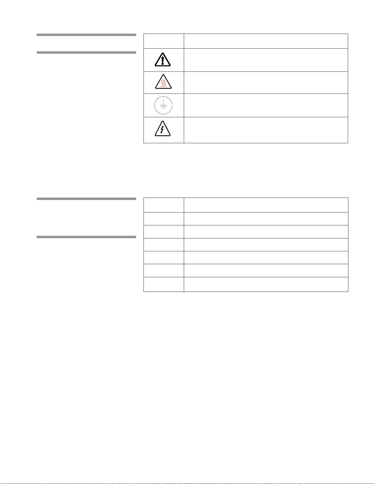
1.1 Symbols on Unit
Symbol Definition
Warning. Refer to Manual For Further
Information.
Transfer of Heat, Hot Surface.
Protective Earth (Ground).
Warning! Risk of Electrical Shock.
1.2 Symbols,
Information on
Nameplate
Symbol Definition
MOD. Model of the Unit.
SER. Serial Number of the Unit.
kW Power Rating of the Unit.
V Voltage Rating of the Unit.
A Amperage Rating of the Unit.
PH/Hz Phase/Hertz – Frequency of the Unit.
Safety Precautions and Symbols Operator Manual 122993-622
1-3

INSTALLATION VERIFICATION
After washer has been installed by qualified service technicians, complete the
2.1 Installation Checklist
following checklist to help ensure the installation is complete and correct.
Contact STERIS and schedule a technician to test the installation and demonstrate proper equipment operation.
❑ Disconnect switches (not provided by STERIS) capable of being locked in
OFF position only for maintenance purposes, installed in electrical supply
lines near unit and in compliance with local occupational health and safety
regulations, as well as electric and plumbing codes for any special requirements that may pertain to installation of this unit.
❑ Shutoff valves (not provided by STERIS) capable of being locked in OFF
position only for maintenance purposes, installed on steam and water lines
and in compilance with local occupational health and safety regulations, as
well as electric and plumbing codes for any special requirements that may
pertain to installation of this unit.
NOTE: If the washer is installed next to other equipment, shutoff valves and
disconnect switch should be placed so service can be shut off to any one unit.
❑ Washer positioned, as shown on equipment drawing, with required service
clearance space and in relation to building supply lines.
❑ Building steam line provides maximum dynamic steam pressure and flow
rate to washer as specified on equipment drawing.
2
❑ Building hot water line supplies water to washer at pressure and temperature
specified on equipment drawing.
❑ If applicable, building cold water line supplies water to washer at pressure
specified on equipment drawing.
❑ If applicable, building pure water line supplies water to washer at pressure
specified on equipment drawing.
❑ Electrical supply for washer is as specified on equipment drawing.
❑ Condensate return is sized as specified on equipment drawing.
❑ Vent connections are sized as specified on equipment drawing.
❑ Wash pump pressure is within 25 to 60 psig.
❑ Proper supply and injection hoses are connected to wash pump.
❑ Rinse pump pressure is within 25 to 60 psig.
❑ Proper chemical supply and injection hoses are connected to rinse pump.
❑ Self-cleaning screen assembly functioning properly.
❑ All piping is leak-free.
❑ Wash section generates a small overflow.
❑ Rinse section generates a small overflow.
❑ Pre-wash spray correctly adjusted (approximately twelve inches above
conveyor belt).
❑ Hydraulic hold-down system correctly balanced.
2-1
Installation Verification Operator Manual 122993-622

❑ Wash solution temperature heated at 140 °F minimum (60 °C minimum).
Wash section steam coil functioning properly.
❑ Rinse water temperature maintained at 180 °F (82 °C). Rinse section steam
coil functioning properly.
❑ Final Rinse water temperature maintained at 185 °F (85 °C) mean value.
❑ Optional Garb-el section is working properly.
❑ All gauges are functioning correctly.
❑ Drive system stop buttons on load- and unload-end control panels function-
ing properly.
❑ Optional photoelectric conveyor stop functioning properly.
❑ Cabinet joints are completely sealed, no leaks. (For verification, run unit for
half an hour.)
IMPORTANT: After a few weeks of operation, inspect unit for leaks. Retighten all clamps and connections.
2.2 Technical
Specifications
2.2.1 Voltage, Amperage, and Power Consumption
The Basil® 6000 Tunnel Cage Washer operates on:
• 208 V~, 60 Hz, three-phase
• 480 V~, 60 Hz, three-phase
The maximum current and power consumptions are:
Model Numbers
Voltage 6024 6024D 6024G 6024GD
208 V 30 Amp 40 Amp 50 Amp 60 Amp
480 V 15 Amp 20 Amp 25 Amp 30 Amp
Model Numbers
Voltage 6036 6036D 6036G 6036GD
208 V 30 Amp 40 Amp 50 Amp 60 Amp
480 V 15 Amp 20 Amp 25 Amp 30 Amp
2-2
122993-622 Operator Manual Installation Verification

2.2.2 Permissible
Environmental Conditions
This equipment is designed to give optimal results in an environment where
maximum relative humidity is 80% for temperatures up to 88 °F (31 °C),
decreasing linearly to 50% relative humidity at 104 °F (40 °C).
2.2.3 Seismic Anchorage System
2.3 Chemical
Additives
Specifications
A seismic anchorage system is available for high-risk seismic zones.
The customer may select what chemical additives to use in the washer,
however, to achieve optimal performance, the selected chemical additives
must meet as a minimum, the following specifications:
Product Use Dilution pH Range Other Applicable
Description Range Oz/Gal at Use Dilution Requirements
Alkaline 1/4 - 4 9.0 - 12.0 liquid, non foaming, and
Chemicals (2 - 32) viscosity below 200 ssu.
Acidic 1/4 - 4 3.0 - 6.0 liquid, non foaming, freeChemicals (2 - 32) rinsing, and viscosity be-
Descalers 1/2 - 2 < 2.5 liquid, non foaming, phos-
(mL/L)(mL/L)
(mL/L)
(mL/L)(mL/L)
low 200 ssu.
(4 - 16) phoric acid-based, and
viscosity below 200 ssu.
Follow detergent label recommendations for concentration of chemical to use.
To achieve maximum cleaning efficiency, select chemical appropriate to soil
type being processed. STERIS recommends the following chemicals:
• Cage-Klenz® 100 Alkaline Cage Wash Detergent - a liquid phosphate-free
detergent formulated for the removal of urine scale, organic soils, and metal
oxides from cage materials.
• Cage-Klenz® 150 Alkaline Cage Wash Detergent - a chlorinated alkaline
detergent formulated for the cleaning of a broad spectrum of soils from
cages and bottles.
• Cage-Klenz® 180 Alkaline Cage Wash Detergent - a general purpose
detergent formulated for the removal of animal fats and oils, organic soils,
and metal oxides from polycarbonate, stainless-steel, and aluminum animal
cages.
• Cage-Klenz® 200 Acid-Based Cage Wash Detergent - a combination of
phosphoric and citric acid film and scale remover for the removal of hard
water scale, urine scale, and metal oxide from on all types of metal surfaces
as well as plastics and glass.
• Cage-Klenz® 220 Acid-Based Cage Wash Detergent - a liquid, phosphate-
free hydroxyacetic detergent formulated to loosen and remove hard water
and urine scale, organic soils, and metal oxides from most metals and
plastics (with the exception of aluminum).
2-3
Installation Verification Operator Manual 122993-622

• Cage-Klenz® 250 Acid-Based Cage Wash Detergent - a liquid phosphate-
free citric acid-based cleaning compound for removal of hard water scale,
urine scale, organic soils, and metal oxides from most types of metal
surfaces as well as plastic and glass.
• Cage-Klenz® 280 Acid-Based Cage Wash Detergent - a cleaner for the
removal of a wide spectrum of soils from most metals, plastics, and glass.
• Liquid Descale Liquid Scale Remover - for removing scale and other hard
water deposits. For use in animal care centers.
NOTE: Certain products may not be available in your area. Contact STERIS
for availability of these products and for ordering information.
IMPORTANT:
STERIS does not promote, recommend nor endorse the use
of any other type of chemical additives in the processing of articles in the Basil
6000 Tunnel Cage Washer, such as drying agents, strong alkaline detergents
(pH>12), alcohol rinses, and liquid germicides including hypochloric acid
(bleach).
2-4
122993-622 Operator Manual Installation Verification

COMPONENT IDENTIFICATION
IMPORTANT: A listing of the Safety Precautions to be observed when operat-
3.1 Washer Sections
ing and servicing this equipment can be found in Section 1 of this manual. Do
not operate or service the equipment until you have become familiar with this
information.
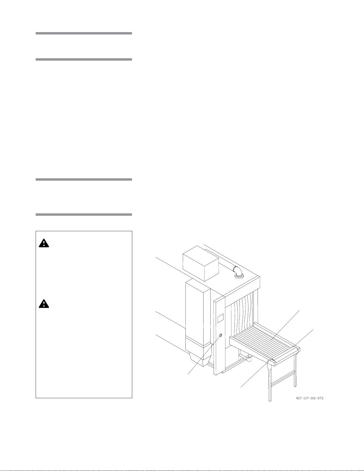
Before operating the unit, it is important to become familiar with the location and
function of all major components and controls (see Figure 3-1).
Items are automatically conveyed through each chamber section, where the
following functions occur:
Optional Garb-el station - disposal unit is installed on the load side of the
conveyor. It provides a quick and easy bedding disposal before wash cycles
into the tunnel washer. Fresh water supply eliminates bedding which passes
through a hammermill pulverizer and then sent to drain.
Use cold water only, except where the Garb-el is used to dispose of large
volumes of greasy plate scrappings. Hot water should be used in such cases
for both sanitary and unit efficiency reasons.
Pre-wash section - water from the rinse recirculating tank is pumped through
spray jet system then sent to drain.
Wash section - hot detergent solution recirculates through the spray jet
system under pump pressure. Solution temperature is maintained by a steam
coil located in the wash recirculating tank.
3
Rinse section - two rinse functions occur within the rinse chamber section:
• Recirculated rinse - hot water recirculates through the spray jet system
under pump pressure. Water temperature is maintained by a steam coil
located in the rinse recirculation tank.
• Final rinse - hot water from building supply, heated by the final rinse heat
exchanger, is sprayed through a separate spray jet system. Water is not
recirculated and falls to rinse recirculating tank.
Optional dryer section - hot air, heated by steam coils, is recirculated through
the dryer chamber where an air knife blow-off system is removing surplus water
from washer item.
3-1
Component Identification Operator Manual 122993-622

Pre-Wash Chamber
Solution Screens
LOAD END
Conveyor
Optional
Garb-el
Section
Pre-Wash Section
Self-Cleaning Screen
Figure 3-1. Side View of Washer
Wash Pump
Solution Screens
Wash Chamber
Rinse Pump
Solution Screens
Rinse Chamber
Final Rinse Heat
Exchanger
Electrical Control Box
Wash Section
Service Access Doors
Rinse Section
Optional Dryer Section
Washer 6000
Garb-El
Dryer Coils
Optional Blower Fan
Conveyor Drive Assembly
UNLOAD END
Proximity Switch
Conveyor Stop
Optional Discharge
Conveyor
3-2
122993-622 Operator Manual Component Identification

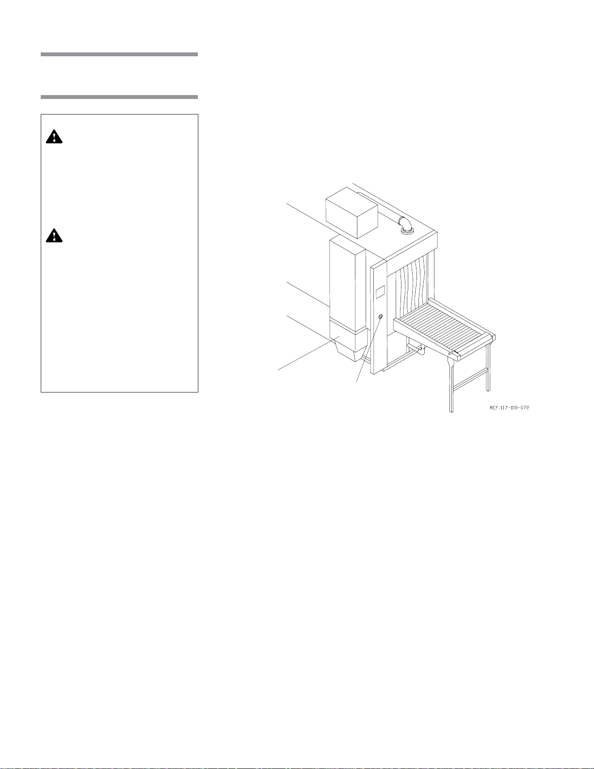
3.2 POWER-OFF/
STANDBY Switch
WARNING– ELECTRICAL
SHOCK AND/OR BURN
HAZARD: POWER-OFF/
STANDBY switch does not
shut ac power off to the
unit.
The POWER-OFF/STANDBY switch supplies unit operation status to the
washer control (see Figure 3-2). Setting the switch to POWER activates the
control and permits unit operation. Setting the switch to OFF/STANDBY places
control in a Standby mode. While in Standby mode, unit operation is not
possible.
NOTE: Control should be placed in Standby mode after the last cycle of the day
and when washer is not in use for an extended period of time.
Printer Door
POWER
OFF
3.3 Control Panel
Display Screen
STANDBY
POWER-OFF/STANDBY
Switch
Printer
Ref.: 920-008-959
Figure 3-2. POWER-OFF/STANBDY Switch Location
The control panel is used to direct all washer functions (see Figure 3-3). The
operator may program specific cycles, review and select cycles, start, stop or
reset cycle operation, extend or by-pass cycle phases, and monitor cycle
performance from the control panel.
Cycle Status Touch Pads
Manual Control Touch Pads
Program Touch Pads
Figure 3-3. Control Panel
3-3
Component Identification Operator Manual 122993-622

3.3.1 Display Screen
3.3.2 Cycle Status Touch Pads
CYCLE
MENU
The two line alpha-numeric screen displays cycle program data on demand,
in-cycle performance data, and operator instructions. Display screen also
indicates certain abnormal conditions that may occur during a cycle.
• CYCLE MENU touch pad - press to view the first cycle menu. Press again
to advance the screen to the next cycle menu. Three menus are available,
each with four cycles.
SELECT
CYCLE
REVIEW
CYCLE
CYCLE
START
STOP
RESET
• SELECT CYCLE touch pad - press until the desired cycle name flashes.
NOTE: When a displayed cycle name or phase value is selected, the
corresponding word or digit flashes.
• REVIEW CYCLE touch pad - press to review the cycle phases and values
programmed for the selected cycle.
• CYCLE/START touch pad - press once to display the name of the selected
cycle. Press a second time to start the cycle.
NOTE: The selected cycle name remains on the screen for five seconds after
pressing CYCLE/START touch pad once. To start a cycle, CYCLE/START
touch pad must be pressed a second time while the selected cycle name is
displayed. If touch pad is not pressed within the five seconds, screen
automatically returns to the cycle menu.
• STOP/RESET touch pad - press once to stop operation of the cycle. Press
a second time to abort cycle and return screen to the cycle menu.
NOTE: When cycle is stopped, press CYCLE/START touch pad once to
resume cycle operation. Cycle operation resumes. When cycle is aborted,
cycle operation is discontinued and cycle must be restarted.
3.3.3 Manual Control Touch Pads
••
• EXTEND PHASE touch pad - press to double the programmed treatment
EXTEND
PHASE
BY-PASS
PHASE
MANUAL
MENU
ALARM
REPLY
3-4
122993-622 Operator Manual Component Identification
••
time while reviewing a cycle in Review Cycle mode, Refer to
Operating Instructions,
••
• BY-PASS PHASE touch pad - press to by-pass the programmed treatment
••
for instructions on extending treatment time.
time while reviewing a cycle in Review Cycle mode, Refer to
Operating Instructions,
for instructions on by-passing treatment time.
Section 4,
Section 4,
• MANUAL MENU touch pad - press to view the washer functions which can
be controlled manually.
• ALARM REPLY touch pad - press to turn off alarm buzzer and acknowledge
the displayed alarm message. Refer to
Section 7, Troubleshooting,
for
specific alarm conditions and corrective actions.

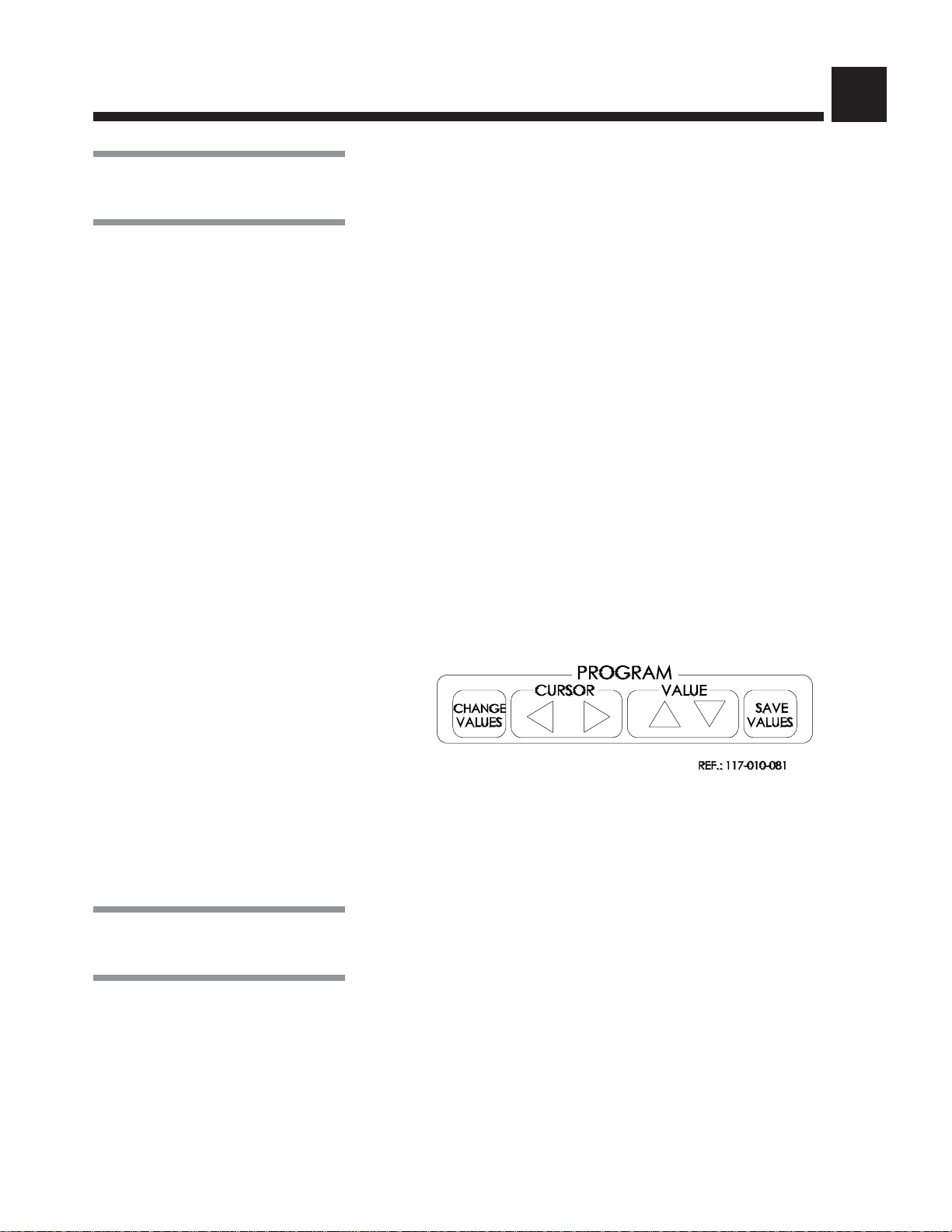
3.3.4 Program Touch Pads
The Program touch pads allow the programming of twelve distinct cycles and
changing of previously programmed cycle values to process different types of
loads. Cycle programming may be limited by access code to ensure process
integrity. Refer to
on cycle programming and access code feature.
Section 5, Cycle and Control Value Programming,
for details
WW
W
WW
SS
S
SS
CHANGE
VALUES
CURSOR
XX
X
XX
VALUE
TT
T
TT
SAVE
VALUES
• CHANGE VALUES touch pad - press to access the Change Values mode.
The Change Values mode allows authorized operators to change the userprogrammable items. Refer to
ming,
for details on the Change Values mode.
NOTE: Examples of user-programmable items include cycle name, phase
temperature, and questions regarding phase options.
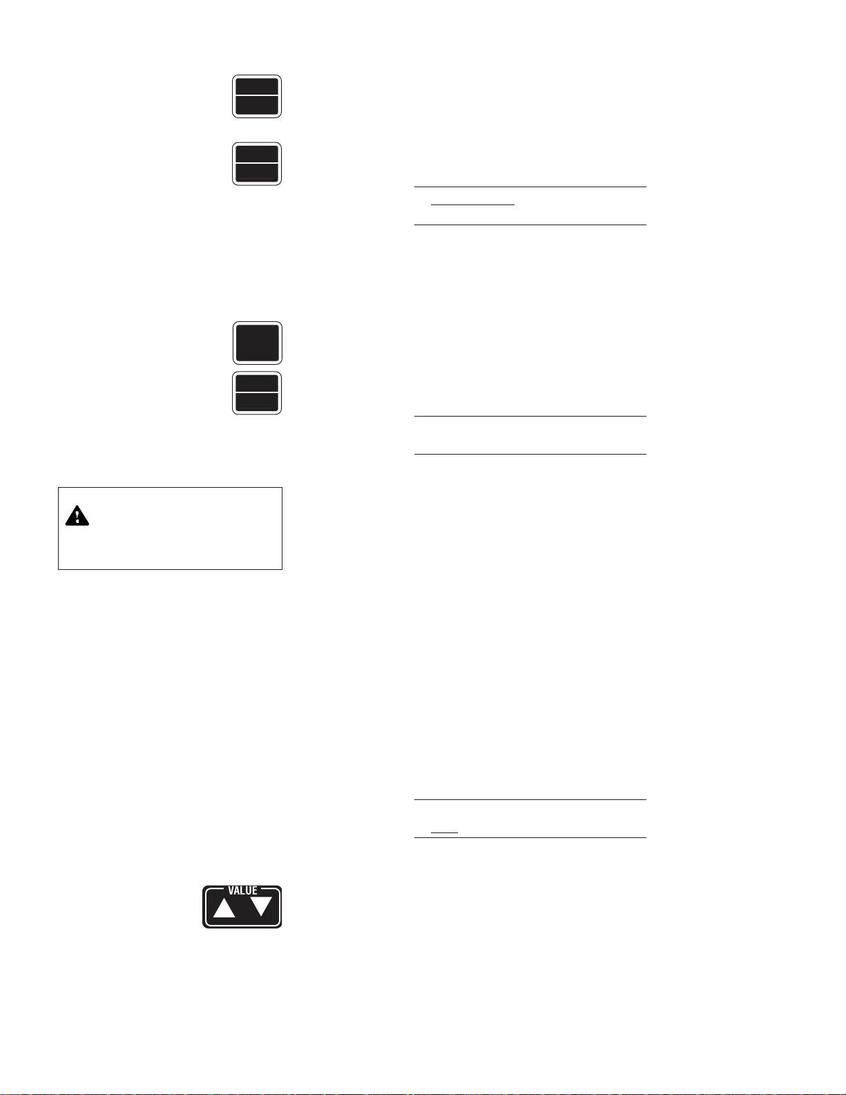
• CURSOR arrows (left or right)
or number) flashes.
• VALUE arrows (up or down) - depending on the item flashing (selected),
press to either toggle between answer selections or scroll through the
alphabet and numbers 0 through 9.
NOTE: Alphabet includes characters for an underline and a space ( ■ ).
• SAVE VALUES touch pad - press to save changes made, exit the Change
Values mode, and return screen to the cycle menu.
Section 5, Cycle and Control Value Program-
- press until item to be changed (word, letter,
3.4 Printer
Thermal Paper
Printer Function Switch
The printer records pertinent cycle data on 2-1/4-inch wide thermal paper (see
Figure 3-4). Refer to
on changing the paper roll and storing thermal paper.
Take-Up Spindle
Section 6.6, Changing Printer Paper Roll,
for information
Figure 3-4. Printer Components
3-5
Component Identification Operator Manual 122993-622

Sample Printouts (see Figures 3-5 and 3-6):
* CONTROL ON HH:MM:SSP
YY/MM/DD
========================
MODEL 6000
S/N 3600000000
========================
========================
CYCLE - CYCLE 1
========================
CYCLE START HH:MM:SS
CYCLE DATE YY/MM/DD
UNIT NUMBER 0000000
---------------------------------------------TANKS DUMP IN XX DAY(S)
AT HH:MM:SS AM
---------------------------------------------HH:MM:SS YY/MM/DD
---------------------------------------------PHASE F
---------------------------------------------AT HH:MM:SS
ALK. WASH SP=XXX.X
ACTUAL TEMP. XXX.X
ACID WASH TEMP. RANGE
LO=XXX.X F HI=XXX.XF
ACTUAL TEMP. 151.3
RINSE SP=XXX.X
ACTUAL TEMP. XXX.X
FINAL RINSE SP=XXX.X
ACTUAL TEMP. XXX.X
*CYCLE PAUSED HH:MM:SS
*CYCLE ABORTED HH:MM:SS
• POWER UP
When POWER-OFF/STANDBY switch is set to POWER, the generated
printout lists time and date the control was turned on, unit serial number, unit
title, and unit model.
• CYCLE START
When CYCLE/START touch pad is pressed twice to begin the selected
cycle, the generated printout lists name of the cycle started, time and date
the cycle was started, the cycle number, unit number, and when the next tank
dump will happen.
• IN-CYCLE PERFORMANCE
During a cycle, the generated printout lists the phase in progress, the
temperature (°F or °C), the time of the printout, the alkaline wash set point
and tank temperature, the acid wash set point and tank temperature, the
rinse set point and tank temperature, and the final rinse set point and tank
temperature.
• CYCLE STOP
When cycle is stopped, printer prints time at which cycle stop was requested.
• CYCLE ABORT
When cycle is aborted, printer prints time at which cycle abort was requested.
• ALARM CONDITION
When an alarm condition occurs, the generated printout lists the type of
alarm and time it occurred (see Figure 3-6). Once the operator presses the
ALARM REPLY touch pad, the generated printout lists the time the alarm
was acknowledged.
Figure 3-5. Sample Printout
-------------------------------------------------*ALARM HH:MM:SSP
-------------------------------------------------DET. TANK
TOO LONG IN FILL
ALARM ACKNOWLEDGED
AT HH:MM:SSP
Figure 3-6. Sample Alarm
Printout
3-6
122993-622 Operator Manual Component Identification

3.5 Unload Side
Control Panel
(Double-Door Units)
3.6 Safety System
3.7 Drive System Control
A remote control column is installed on the unload side of the unit. This remote
control column is wired directly to the main control processor and includes a
control panel. Most washer functions can be directed from this control panel,
and the display screen concurrently shows the same cycle performance data
as the load-side control panel. There is no printer on remote control column.
Service doors are equipped with a safety switch to stop washer operation if one
of doors is opened during a cycle and to prevent start of washer operation if
door is not securely closed. Load-side and unload-side have a drive system
EMERGENCY STOP pushbutton.
Load-side and unload-side control panels are also equipped with STOP/
RESET touch pads. Press touch pad once to stop cycle operation and twice
to abort cycle.
Additional controls affecting the drive system are located on the front of the
electrical control box (see Figure 3-7).
• MANUAL DRIVE SYSTEM - position switch to ON to run conveyor only.
• ADJUSTABLE BELT SPEED - position dial to desired conveyor speed from
low to high.
• PROXIMITY SWITCH BYPASS - position switch to ON to bypass proximity
switch.
MANUAL DRIVE
SYSTEM
LOW HIGH
ADJUSTABLE BELT SPEED
PROXIMITY SWITCH
BYPASS
ON
OFF
Figure 3-7. Drive Sytem Control
3-7
Component Identification Operator Manual 122993-622

3.8 Hydraulic HoldDown System
WARNING – BURN HAZARD: Do not adjust balancing valve while washer is
operating.
Hydraulic hold-down system allows control of the water pressure exiting the spray
jet systems during cycle operation. By decreasing the water pressure to the lower
spray jets, the downward pressure from the upper jets will hold the product down
on the conveyor (see
Section 6.15, Adjust Hydraulic Hold-Down System
).
System includes balancing valves installed in the water supply lines, located inside
the wash, rinse and final rinse chambers, on opposite side of chamber from the
access door (see Figure 3-8). Balancing valve is a ball valve with a blue handle.
Balancing Valve
3.9 Garb-el Control Panel (Option)
Figure 3-8. Spray System Balancing Valve
The Garb-el control panel is used to direct Garb-el functions (see Figure 3-9).
• GARB-EL AND DRIVE SYSTEM STOP - pull to operate Garb-el and push
to stop Garb-el and washer belt drive.
IMPORTANT:
stops instantly but water and pulverizer mechanism continue to run for up to
five minutes to provide extra flushing of the waste line.
• GARB-EL SYSTEM ON/OFF - position to ON to run Garb-el. Feeder
mechanism and pulverizer start simultaneously.
When Garb-el is placed in OFF position, feeder mechanism
GARB-EL AND DRIVE
SYSTEM STOP
GARB-EL SYSTEM
OFF ON
Figure 3-9. Garb-el Control Panel
3-8
122993-622 Operator Manual Component Identification

OPERATING INSTRUCTIONS
IMPORTANT: A listing of the Safety Precautions to be observed when operat-
4.1 Before
Operating Washer
WARNING– CHEMICAL
BURN AND/OR EYE INJURY
HAZARD: Detergents are
caustic and can cause adverse effects to exposed tissues. Do not get in eyes, on
skin, or attempt to swallow.
Read and follow the precautions and instructions on
the detergent label and in
the Material Safety Data
Sheet (MSDS) prior to handling the detergent, refilling
the detergent container, or
servicing the detergent injection pump. Wear appropriate Personal Protective
Equipment (PPE) whenever
handling the detergent or
servicing the detergent injection pump and lines.
ing and servicing this equipment can be found in Section 1 of this manual. Do
not operate or service the equipment until you have become familiar with this
information.
1. Ensure building electrical supply disconnect switch (circuit breaker) is
positioned to ON. Verify steam and water supply valves are open.
2. Open service access doors and ensure chambers are empty.
3. Verify chamber solution screens are clean and in place (see Figure 4-1)
and screen access panels are secure.
4. Ensure all service access doors are closed securely.
5. Verify detergent supply (provided by customer). Ensure supply hose is
correctly placed in detergent container.
NOTE: Always use a non-foaming detergent for effective cleaning and
proper pump and water level control operation. To achieve maximum
cleaning efficiency, select detergent appropriate to soil type being processed.
4
WARNING – BURN HAZARD: Do not reach into
sump.
WARNING – SLIPPING
HAZARD: To avoid slippery
floor conditions, immediately wipe up any spilled liquids or drippage. If spilled
liquids or drippage are detergents or other chemicals,
follow safety precautions
and handling procedures set
forth on detergent or chemical label and/or Material
Safety Data Sheet (MSDS).
CAUTION – POSSIBLE
EQUIPMENT DAMAGE:
When choosing a detergent,
select one with a low chloride content. Detergents
with a high chloride content
can corrode stainless steel.
Figure 4-1. Two-Piece Solution Screen
4-1
Operating Instructions Operator Manual 122993-622

4.2 Loading Unit
WARNING – PERSONAL
INJURY AND/OR EQUIPMENT DAMAGE HAZARD:
Always load baskets on
appropriate loading cart or
surface.
If Garb-el option is not present,
1. Empty all soiled bedding from cages before placing them inside washer.
2. Load feeder bottles upside down in appropriate accessory.
3. Place items to be washed upside down on load table. Push slightly until
conveyor belt inside pre-wash chamber routes items or accessory inside
chamber.
or
If load-side conveyor option is present, place items upside down on
conveyor. Conveyor transports items inside chamber automatically.
load items to be washed as follows:
4.3 EMERGENCY
STOP Pushbutton
WARNING – PERSONAL
INJURY AND/OR EQUIPMENT DAMAGE HAZARD:
In case of an emergency
situation involving conveyors, always press EMERGENCY STOP pushbutton
to stop all washer and conveyor operations.
If Garb-el option is present,
1. Place Garb-el ON/OFF switch to ON (see Figure 3-9).
2. Place cage containing soiled bedding upside down on Garb-el screen.
Cage is shaken to empty soiled bedding into grinder hopper.
IMPORTANT:
3. Push cage on washer load table until conveyor belt inside pre-wash
chamber routes cage inside chamber.
or
If load-side conveyor option is present,
so cage is loaded automatically inside pre-wash chamber.
There is a red EMERGENCY STOP pushbutton located at each end of the unit.
Both pushbuttons stop the drive belt. Also, unload-end EMERGENCY STOP
pushbutton stops dryer section.
If Gab-el option is present, press Garb-el and drive system STOP pushbutton
(see Figure 3-9) to stop washer conveyor and Garb-el operations simultaneously.
Do not cram or pack the waste in grinder hopper.
load items to be washed as follows:
push cage slightly on conveyor
4-2
122993-622 Operator Manual Operating Instructions

4.4 Cycle Operation
WARNING– ELECTRICAL
SHOCK AND/OR BURN
HAZARD: POWER-OFF/
STANDBY switch does not
shut ac power off to the
unit.
Cycle Temperature
Phase
The Basil® 6000 Tunnel Cage Washer is equipped with a microcomputer
control capable of storing parameters for twelve distinct cycles. Authorized
operators have capability of customizing/programming all the cycles to meet
specific washing needs. For instructions on cycle programming or changing
cycle parameters, refer to
Section 5, Cycle and Control Value Programming
On initial receipt of washer, each cycle is set with a basic demonstration cycle
consisting of sections of the unit, for example Pre-Wash, Alkaline Wash, Rinse,
Final Rinse, and Dry. Refer to Table 4-1 for phase values of the demonstration
cycle.
To begin cycle operation:
1. Set POWER-OFF/STANDBY switch, located behind printer door, to
POWER.
Unit name temporarily appears, then display shows first cycle menu:
.
Pre-wash Same as
Rinse Tank
Alk. Wash 140°F (60°C)
OR
Acid Wash 140°F (60°C)
Rinse 180°F (82°C)
Final Rinse 180°F (82°C)
Drying Manually Adjusted
Table 4-1. Demonstration
Cycle Phase Values
CYCLE
MENU
SELECT
CYCLE
CYCLE 1 CYCLE 2
CYCLE 3 CYCLE 4
_ Indicates flashing position
and printer message is:
* CONTROL ON HH:MM:SS
MM:DD:YY
===========================
MODEL 6XXX
S/N 36XXXXXXXXXX
============================
2. Press CYCLE MENU touch pad until desired cycle menu appears. Display
shows:
CYCLE 9 CYCLE 10
CYCLE 11 CYCLE 12
_ Indicates flashing position
3. Press SELECT CYCLE touch pad until desired cycle name flashes.
Display shows:
CYCLE 9 CYCLE 10
CYCLE 11 CYCLE 12
_ Indicates flashing position
CYCLE
START
4. When desired cycle name is flashing, press CYCLE/START touch pad.
Name of selected cycle appears and remains displayed for five seconds.
Display shows:
CYCLE 9 CYCLE 10
CYCLE 11 CYCLE 12
__ Indicates flashing position
4-3
Operating Instructions Operator Manual 122993-622

CYCLE
START
5. To start selected cycle, press CYCLE/START touch pad a second time
while selected cycle name is displayed.
NOTE: If
CYCLE/START
touch pad is not pressed a second time while the
selected cycle name is displayed, display automatically returns to the cycle
menu.
Once selected cycle is started, printer message is:
==============================
CYCLE - CYCLE 01
=============================
CYCLE START HH:MM:SS
CYCLE DATE MM:DD:YY
UNIT NUMBER 36XXXXXXXX
------------------------------------------------------TANKS DUMP IN XX DAYS
AT HH:MM:SS AM
-------------------------------------------------------
Washer automatically progresses through selected cycle.
NOTE: When operating the unit, note the following:
1) If temperature guarantee feature is selected, belt stops if the solution/
water temperature in chamber sump is lower than the set point. There is a
G after temperature on the display if the guarantee is on.
2) Cycle operation may be halted at any time by pressing
touch pad once. To resume cycle operation, press
pad.To abort cycle operation, press
STOP/RESET
CYCLE/START
STOP/RESET
touch
touch pad a second
time.
During cycle, display alternates between following messages, every four
seconds:
ALK. TEMP = XXX.X F
ACID* TEMP = XXX.X F
*RINSE if acid is not present.
and:
RINSE TEMP = XXX.X F
FINAL RINSE* = XXX.X F
*Only if unit has two wash chambers.
NOTE: If proximity switch conveyor stop option is provided, washer must
be equipped with the discharge conveyor option. Proximity switch conveyor
stop can only be installed in the optional discharge conveyor.
Printer records tank temperatures on a timed interval set in operating
values menu. In each section, the following occurs:
• •
• PRE-WASH
• •
Hot water from the rinse tank is sprayed on load and goes down the
drain.
••
• ACID OR ALKALINE WASH
••
Heated detergent solution from the alkaline or acid sump is pumped
through the spray header, over and under the load, then falls back into
the alkaline or tank sump to be recirculated.
4-4
122993-622 Operator Manual Operating Instructions

4.5 Stop Cycle
• RINSE
Heated water from the rinse sump is pumped through the spray header
over and under the load, then falls back into the rinse sump to be
recirculated.
• FINAL RINSE
Hot water from building supply is fed through an instantaneous heat
exchanger, through the final rinse spray header, and falls into the rinse
tank.
NOTE: If temperature guarantee feature is selected for the Final Rinse,
the display shows a G after the Final Rinse temperature. The belt only
runs if the temperature is greater or equal to set point.
• DRYING (OPTION)
Hot air recirculates through drying section. An air knife blow-off system
removes surplus water from washed items.
STOP
RESET
CYCLE
START
1. Press STOP/RESET touch pad to immediately halt operation of cycle in
progress. Display indicates cycle was stopped:
PRESS STOP TO ABORT
OR START TO RESUME
and printer message is:
*CYCLE PAUSED HH:MM:SSP
2. Press CYCLE/START touch pad to resume cycle operation. Display shows:
ALK. TEMP = XXX.X F
ACID TEMP = XXX.X F
and:
RINSE TEMP = XXX.X F
FINAL RINSE = XXX.X F
and printer message is:
*CYCLE RESUMED HH:MM:SSP
4-5
Operating Instructions Operator Manual 122993-622

4.6 Abort Cycle
STOP
RESET
STOP
RESET
4.7 Control
Conveyor Belt,
Pumps, and Drain
Operations
1. Press STOP/RESET touch pad to halt cycle in progress.
2. Press STOP/RESET touch pad a second time to abort cycle. Display
indicates cycle was aborted:
CYCLE ABORTED...
and printer message is:
*CYCLE ABORTED HH:MM:SSP
Control automatically returns to selected cycle menu. Display shows:
CYCLE 1 CYCLE 2
CYCLE 3 CYCLE 4
__Indicates flashing position.
The user may manually control certain washer functions by accessing the
Manual Control mode when a cycle is not in progress.
MANUAL
MENU
SELECT
CYCLE
CYCLE
START
STOP
RESET
4-6
122993-622 Operator Manual Operating Instructions
1. Press MANUAL MENU touch pad to access Manual Control mode:
MANUAL CONTROL MODE
and to display menu of available manual functions:
RUN BELT PUMPS
TNK DUMP
__Indicates flashing position.
2. Use SELECT CYCLE touch pad to move around menu.
3. When desired choice is flashing, press CYCLE/START touch pad.
4. Pressing STOP/RESET touch pad will return you to cycle menu.

4.7.1 Run Belt (or Stop Belt)
CYCLE
START
CYCLE
START
4.7.2 Pumps
CYCLE
START
Used to energize/de-energize drive belt motor. If RUN BELT is flashing and
CYCLE/START touch pad is pressed, display shows:
PRESS START TO RUN
BELT DRIVE
If STOP BELT is flashing and CYCLE/START touch pad is pressed, display
shows:
BELT DRIVE
STOPPED
Program returns to Manual Control mode main menu.
If PUMPS is flashing and CYCLE/START touch pad is pressed, and access
code is turned on, display shows:
DO YOU KNOW ACCESS
CODE? NO
SELECT
CYCLE
CYCLE
START
__Indicates flashing position.
1. Use VALUE arrows (up or down) to change NO to YES. Display shows:
ENTER ACCESS
CODE=0000
__Indicates flashing position.
If access code is entered correctly, display shows:
WASH RINSE
DRYER ALL
__Indicates flashing position.
2. Use SELECT CYCLE touch pad to select pump(s).
3. Press CYCLE/START touch pad to energize. Desired pump(s) is (are)
energized and then control returns to Pumps menu.
• WASH: energizes alkaline and acid pumps.
• RINSE: energizes rinse pump.
• DRYER: energizes dryer blower and dryer steam.
• ALL: energizes all of the above.
4-7
Operating Instructions Operator Manual 122993-622
STOP
RESET
4. Press STOP/RESET touch pad to turn off all pumps and return to Manual
Mode menu.
CYCLE
START
4.7.3 Tank Dump
SELECT
CYCLE
CYCLE
START
WARNING– BURN HAZARD:
Water discharge may be
extremely hot.
Used to open selected drain ball valve during tank drain time set. If TANK
DUMP is flashing and CYCLE/START
touch pad is pressed, display shows:
WASH TANK RINSE
ALL TANKS ALK/RINSE
__Indicates flashing position.
1. Use SELECT CYCLE touch pad to select tank(s).
2. Press CYCLE/START touch pad to start. Desired tank(s) dumps and then
control return to Tank Dump menu. Displays shows (typical):
WASH TANK DUMP
TIME = MM:SS
and printer message is:
MM:SS PM YY/MM/SS
============================
= MANUAL TANK(S) DUMP =
============================
• ALK.: opens alkaline drain ball valve for TANK DRAIN time.
• RINSE: opens rinse drain ball valve for TANK DRAIN time.
• ACID: opens acid drain ball valve for TANK DRAIN time.
• ALL: opens all drain ball valves for TANK DRAIN time.
NOTE: Tank drain time can be modified in Change Values mode (see
Section 5.2, Change Values Mode).
3. When selected tank has been drained, it is possible to refill it. Display shows:
REFILL TANK(S)?
YES
__Indicates flashing position.
4. Use VALUE arrows (up or down)
to select YES or NO.
If YES is selected, tank starts filling and heating.
If NO is selected, the tank drain ball valve(s) closes, so unit can be powered
down and tanks rinsed out. In power up, ball valve(s) closes and tanks fill
and heat.
4-8
122993-622 Operator Manual Operating Instructions
4.8 Shutdown Procedure
At the end of a work session, the washer should be shut down and cleaned
thoroughly. Refer to
instructions and scheduled minor maintenance.
1. Access Manual Control mode and drain tanks as explained in
tion 4.7.3, Tank Dump
2. Position POWER-OFF/STANDBY switch to OFF/STANDBY.
3. Position building electrical disconnect switch (circuit breaker) to OFF and
close building supply valves.
Section 6, Routine Maintenance,
.
for complete cleaning
Sec-
4.9 Proximity
Switch Conveyor
Stop
WARNING – BURN HAZARD: When unloading processed items from conveyor,
wear appropriate Personal
Protective Equipment
(PPE ). Clean items may be
extremely hot or contain hot
rinse water.
4. Clean unit as described in
5. Ensure building electrical disconnect switch is positioned to ON after
completion of cleaning and minor maintenance procedures.
Section 6.3, Daily Cleaning Procedures
.
NOTE: Leaving disconnect switch in OFF position overnight will shorten life
span of battery backed-up control memory.
A proximity switch, located at the end of the optional discharge conveyor,
stops the conveyor drive system when an item reaches the end of the conveyor
(see Figure 4-2).
WARNING – SLIPPING
HAZARD: To avoid slippery
floor conditions, immediately wipe up any spilled
liquids or drippage. If
spilled liquids or drippage
are detergents or other
chemicals, follow safety
precautions and handling
procedures set forth on
detergent or chemical label
and/or Material Safety Data
Sheet (MSDS).
EMERGENCY STOP
Pushbutton
Proximity Switch
Optional Discharge Conveyor
(by Gravity or Powered)
Basket Barrier
Figure 4-2. Optional Discharge Conveyor
4-9
Operating Instructions Operator Manual 122993-622
4.10 Dryer Section (Option)
WARNING – BURN HAZARD: When unloading processed items from conveyor,
wear appropriate Personal
Protective Equipment
(PPE ). Clean items may be
extremely hot or contain hot
rinse water.
WARNING – SLIPPING
HAZARD: To avoid slippery
floor conditions, immediately wipe up any spilled
liquids or drippage. If
spilled liquids or drippage
are detergents or other
chemicals, follow safety
precautions and handling
procedures set forth on
detergent or chemical label
and/or Material Safety Data
Sheet (MSDS).
A stainless-steel hot air dryer section is built into washer at the unload end (see
Figure 4-3). During normal cycle operation, hot air recirculates through this
section. Recirculated air temperature is adjustable up to 210 °F (99 °C). An
air-knife blow-off system removes surplus water from washed items.
Dryer Coils and Blower Fan
EMERGENCY STOP
Pushbutton
Figure 4-3. Dryer Section (Option)
4-10
122993-622 Operator Manual Operating Instructions
CYCLE AND CONTROL VALUE PROGRAMMING
IMPORTANT: A listing of the Safety Precautions to be observed when
5.1 Program Touch Pads
operating and servicing this equipment can be found in Section 1 of this
manual. Do not operate or service the equipment until you have become
familiar with this information.
The microprocessor control of the Basil® 6000 Tunnel Cage Washer allows the
adjustment of previously programmed cycles to process different types of
loads. All program changes are made using the program touch pads on the
washer control panel.
Program touch pads function as follows (see Figure 5-1):
• CHANGE VALUES touch pad - press to access Change Values mode.
• CURSOR arrows (left or right) - press until item to be changed (word, letter,
or number) flashes.
• VALUE arrows (up or down) - depending on the item flashing (selected),
press to either toggle between answer selections or scroll through the
alphabet and numbers 0 through 9.
NOTE: Alphabet includes characters for an underline and a space ( ■ ).
5
5.2 Change Values Mode
• SAVE VALUES touch pad - press to save changes made, exit the Change
Values mode, and return screen to the cycle menu.
Figure 5-1. Program Touch Pads
The Change Values mode allows authorized operators to change both the
cycle values and general operating values. In Change Values mode, the cycles
may be altered and saved as custom cycle programs to meet specific washer
needs.
5-1
Cycle and Control Value Programming Operator Manual 122993-622

5.2.1 Programming Cycle Values
WARNING– ELECTRICAL
SHOCK AND/OR BURN
HAZARD: POWER-OFF/
STANDBY switch does not
shut the ac power off the
unit.
CYCLE
MENU
SELECT
CYCLE
The following procedure is based on a washer equipped with certain optional
features. This washer displays messages pertaining to specific optional
functions. The specific optional messages change the sequence of messages
and additional messages are shown in the following pages to accommodate
various washer configurations.
1. Set POWER-OFF/STANDBY switch, located behind printer door, to
POWER. Unit name temporarily appears, then display shows first cycle
menu:
CYCLE 1 CYCLE 2
CYCLE 3 CYCLE 4
__Indicates flashing position.
2. Press CYCLE MENU touch pad until desired cycle menu appears. Display
shows:
CYCLE 9 CYCLE 10
CYCLE 11 CYCLE 12
__Indicates flashing position.
3. Press SELECT CYCLE touch pad until desired cycle name flashes.
Display shows:
CYCLE 9 CYCLE 10
CYCLE 11 CYCLE 12
CHANGE
VALUES
__ Indicates flashing position.
4. When desired cycle name is flashing, press CHANGE VALUES touch pad
to access Change Values mode. Printer message is:
*CHANGE VALUE HH:MM:SSP
and first Change Values display appears:
CHANGE CYCLE NAME
CYCLE 10
__ Indicates flashing position.
NOTE: When changing values, note the following:
1) If access code feature is enabled and the selected cycle is locked out,
the access code sequence appears after
CHANGE VALUES
touch pad is
pressed.
2) Change Values mode may be exited at any time by pressing
VALUES
touch pad. Control saves changed values and returns to selected
SAVE
cycle menu.
5. To change cycle name, press CURSOR arrows (left or right) touch pad to
advance flashing position one space at a time. Press VALUE arrows (up
or down) touch pad to select desired letter, number, punctuation, or
space. Cycle name can be a maximum of nine characters including
spaces.
NOTE: Pressing
CURSOR arrows
(left or right) or
VALUE arrows
(up or
down) repeatedly in one direction cycles through all available positions or
letters and numbers.
5-2
122993-622 Operator Manual Cycle and Control Value Programming

CHANGE
VALUES
6. Press CHANGE VALUES touch pad. Alkaline wash selection appears.
Display shows:
ALK. WASH THIS
CYCLE? YES
__Indicates flashing position.
7. Press VALUE arrows (up or down) to toggle between YES and NO.
Selecting NO by-passes alkaline wash tank function during cycle (go to
Step 17). Selecting YES provides alkaline wash during cycle.
CHANGE
VALUES
CHANGE
VALUES
NOTE: Change Values mode may be exited at any time by pressing
VALUES
touch pad. Control saves changed values and returns to selected
SAVE
cycle menu.
8. Press CHANGE VALUES touch pad. Alkaline wash tank temperature
display appears:
CYCLE 1 SP = 140.0 F
ALKALINE WASH TANK
__ Indicates flashing position.
9. To enter Wash temperature set point, press CURSOR arrows (left or right)
to select position and VALUE arrows (up or down) to select desired
number (0-9). Temperature set point is input as any number value to 1/10
of a degree.
NOTE: When changing values, note the following:
1) With any tank temperature guarantee feature enabled, the belt does no t
start unless set point is reached. It is important set point be an attainable value.
2) Change Values mode may be exited at any time by pressing
VALUES
touch pad. Control saves changed values and returns to selected
SAVE
cycle menu.
10. Press CHANGE VALUES touch pad. Alkaline wash tank temperature
guarantee option appears. Display shows:
th
GUARANTEE ALK. TEMP?
NO
__ Indicates flashing position.
11. Press VALUE arrows (up or down) to toggle between YES and NO.
Selecting NO starts belt as soon as cycle starts. Selecting YES guarantees
acid wash tank temperature is equal to or greater than programmed set
point before belt starts.
NOTE: With any temperature guarantee feature enabled, the belt does not
start unless set point is reached.
CHANGE
VALUES
12. Press CHANGE VALUES touch pad. Display shows:
ACID WASH THIS
CYCLE? YES
__ Indicates flashing position.
5-3
Cycle and Control Value Programming Operator Manual 122993-622

13. Press VALUE arrows (up or down) to toggle between YES and NO.
Selecting NO by-passes acid wash tank function during cycle. Selecting
YES provides acid wash during cycle.
CHANGE
VALUES
CHANGE
VALUES
NOTE: Change Values mode may be exited at any time by pressing
VALUES
touch pad. Control saves changed values and returns to selected
SAVE
cycle menu.
14. Press CHANGE VALUES touch pad. Acid wash tank temperature guar-
antee option appears. Display shows:
GUARANTEE ACID TEMP?
NO
__ Indicates flashing position.
15. Press VALUE arrows (up or down) to toggle between YES and NO.
Selecting NO starts belt as soon as cycle starts. Selecting YES guarantees
acid wash tank temperature is equal to or greater than programmed set
point before belt starts.
NOTE: When changing values, note the following:
1) With any temperature guarantee feature enabled, the belt does not start
unless set point is reached.
2) Change Values mode may be exited at any time by pressing
VALUES
touch pad. Control saves changed values and returns screen to
SAVE
selected cycle menu.
16. Press CHANGE VALUES touch pad. Rinse tank temperature option
appears. Display shows:
CYCLE 1 SP=180.0 F
RINSE TANK
CHANGE
VALUES
__Indicates flashing position.
17. To enter rinse temperature set point, press CURSOR arrows (left or right)
to select position and VALUE arrows (up or down) to select desired
number (0 to 9). Temperature set point is input as any number value to 1/
10th of a degree.
NOTE: When changing values, note the following:
1) With any tank temperature guarantee feature enabled, the belt does not
start unless set point is reached. It is important set point be an attainable value.
2) Change Values mode may be exited at any time by pressing
VALUES
touch pad. Control saves changed values and returns screen to
SAVE
selected cycle menu.
18. Press CHANGE VALUES touch pad. Rinse tank temperature guarantee
option appears. Display shows:
GUARANTEE RINS TEMP
NO
__ Indicates flashing position.
5-4
122993-622 Operator Manual Cycle and Control Value Programming

CHANGE
VALUES
19. Press CHANGE VALUES touch pad. Final rinse temperature display
appears:
CYCLE 1 SP=180.0 F
FINAL RINSE
__ Indicates flashing position.
20. To enter final rinse temperature set point, press CURSOR arrows (left or
right) to select position and VALUE arrows (up or down) to select desired
number (0-9). Temperature setpoint is input as any number value to 1/10
of a degree.
NOTE: When changing values, note the following:
1) With any tank temperature guarantee feature enabled, the belt does not
start unless set point is reached. It is important set point be an attainable value.
2) Change Values mode may be exited at any time by pressing SAVE
VALUES touch pad. Control saves changed values and returns screen to
selected cycle menu.
th
CHANGE
VALUES
CHANGE
VALUES
21. Press CHANGE VALUES touch pad. Final rinse temperature guarantee
option appears. Display shows:
GUARANTEE FINAL RINS
NO
__ Indicates flashing position.
22. Press VALUE arrows (up or down) to toggle between YES and NO.
Selecting NO starts belt as soon as cycle starts. Selecting YES guarantees
final rinse water temperature is equal to or greater than programmed set
point, before belt starts.
NOTE: When changing values, note the following:
1) With any temperature guarantee feature enabled, the belt does not start
unless set point is reached.
2) Change Values mode may be exited at any time by pressing
VALUES
touch pad. Control saves changed values and returns to selected
SAVE
cycle menu.
23. Press CHANGE VALUES touch pad. Display shows:
DRY THIS CYCLE?
YES
__ Indicates flashing position.
24. Use CURSOR arrows (left or right) and VALUE arrows (up or down) to
turn dryer section ON or OFF.
CHANGE
VALUES
25. Press CHANGE VALUES touch pad. Print cycle values option appears.
Display shows:
PRINT CYCLE VALUES?
NO
__ Indicates flashing position.
5-5
Cycle and Control Value Programming Operator Manual 122993-622

26. Press VALUE arrows (up or down) to toggle between YES and NO.
Selecting YES generates a printout of cycle phase values once SAVE
VALUES touch pad or CHANGE VALUES touch pad is pressed.
27. At any point during change values sequence, operator has the option to
either continue in Change Values mode or to save values and exit Change
Values mode.
SAVE
VALUES
CHANGE
VALUES
• To exit Change Values mode, press SAVE VALUES touch pad. Control
saves changed values and returns to selected cycle menu. Display
shows:
CYCLE 9 CYCLE 10
CYCLE 11 CYCLE 12
__ Indicates flashing position.
• To continue in Change Values mode, press CHANGE VALUES touch
pad. Change operating values option appears. Display shows:
CHANGE OPERATING
VALUES? NO
__Indicates flashing position.
NOTE: Refer to Section 5.2.2, Programming Operating Values, for
details on continuing in the Change Values mode.
5-6
122993-622 Operator Manual Cycle and Control Value Programming

5.2.2 Programming Operating Values
The following procedure is based on a washer equipped with certain optional
features. This washer shows messages pertaining to specific optional functions. The specific optional messages change the sequence of messages and
additional messages are shown in the following pages to accommodate
various washer configurations.
NOTE: The demonstration cycle is set with the access code feature OFF.
1. Set POWER-OFF/STANDBY switch, located behind printer door, to
POWER. Unit name temporarily appears, then display shows first cycle
menu:
CYCLE 1 CYCLE 2
CYCLE 3 CYCLE 4
__ Indicates flashing position.
CHANGE
VALUES
CHANGE
VALUES
2. Press CHANGE VALUES
touch pad to access Change Values mode.
NOTE: Access to operating values may be made through any cycle.
First change values display appears:
CHANGE CYCLE NAME
CYCLE 1
__ Indicates flashing position.
NOTE: Change Values mode may be exited at any time by pressing
VALUES
touch pad. Control saves changed values and returns to selected
SAVE
cycle menu.
3. Press CHANGE VALUES touch pad several times to advance through
phase values displays until print cycle values option appears. Display
shows:
PRINT CYCLE VALUES?
NO
__ Indicates flashing position.
4. Press
VALUE arrows (up or down) to toggle between YES and NO.
NOTE: Selecting YES generates a printout of the cycle phase values once
SAVE VALUES
touch pad or
CHANGE VALUES
touch pad is pressed.
CHANGE
VALUES
5. Press CHANGE VALUES touch pad. Change operating values option
appears. Display shows:
CHANGE OPERATING
VALUES? NO
__ Indicates flashing position.
CHANGE
VALUES
6. Press CHANGE VALUES touch pad
..
. Display shows:
..
PRINTER ENABLED?
YES
__ Indicates flashing position.
5-7
Cycle and Control Value Programming Operator Manual 122993-622

7. Press
VALUE arrows (up or down) to toggle between YES and NO.
CHANGE
VALUES
CHANGE
VALUES
8. Press CHANGE VALUES touch pad
..
. If timed printout option is ON, display
..
shows:
PRINTOUT = MM:SS
__ Indicates flashing position.
9. Use CURSOR arrows (left or right) and VALUE arrows (up or down) to
set time interval between printing out tank temperature and tank temperature details.
10. Press CHANGE VALUES. Date and time display appears:
DATE YY/MM/JJ
TIME HH:MM:SSA
__Indicates flashing position.
11. To enter correct date and time, press CURSOR arrows (left or right) to
advance flashing position one space at a time. Press VALUE arrows (up
or down) to select desired number (0-9). Date is input as two-digit
numerical values for Year/Month/Day. Time is input as Hour/Minute/
Seconds.
NOTE: Pressing
CURSOR arrows
(left or right) or
VALUE arrows
(up or
down) repeatedly in one direction cycles through all available positions or
letters and numbers.
CHANGE
VALUES
12. Press CHANGE VALUES touch pad. Automatic dump day and time
interval appears. Display shows:
AUTO DUMP T= XX DAYS
DUMP AT= HH:MM
__ Indicates flashing position.
13. Use CURSOR arrows (left or right) and VALUE arrows (up or down) to
set automatic day interval between dumps and time at which dumping
occurs.
5-8
122993-622 Operator Manual Cycle and Control Value Programming

5.3 Programming
Values With Access
Code Enabled
The access code feature is used to prevent unauthorized changes to the
parameters of designated cycles and/or operating values. With this feature,
access to cycle values may be selectively limited to authorized operators,
depending on the security needs of the washer environment. When access
code is enabled, only authorized operators can change operating values
regardless of cycles locked out.
The following procedure provides examples of how to access Change Values
mode when the access code feature is enabled.
CHANGE
VALUES
CHANGE
VALUES
1. When desired cycle name is flashing, press CHANGE VALUES touch pad
to access Change Values mode. Printer message is:
* CHANGE VALUE HH:MM:SSP
and, if selected cycle is locked out, display shows:
DO YOU KNOW ACCESS
CODE? NO
__ Indicates flashing position.
2. Press VALUE arrows (up or down) to toggle between YES and NO. If NO
is selected, control returns to cycle menu once CHANGE VALUES touch
pad is pressed.
3. Press CHANGE VALUES touch pad. If YES was selected, display shows:
ENTER ACCESS CODE
CODE=0000
__ Indicates flashing position.
4. To enter access code, press CURSOR arrows (left or right) to advance
flashing position one space at a time. Press VALUE arrows (up or down) to
select desired number (0 - 9). If an incorrect access code is entered, control
returns to cycle menu once CHANGE VALUES touch pad is pressed.
NOTE: Pressing
CURSOR arrows
(left or right) or
VALUE arrows
(up or
down) repeatedly in one direction cycles through all available positions or
letters and numbers.
CHANGE
VALUES
5. Press CHANGE VALUES touch pad. First change values display ap-
pears:
CHANGE CYCLE NAME
CYCLE 1
__Indicates flashing position.
At this point, operator has access to all phase values displays of selected
cycle and operating values displays. Sequence and procedures for
changing cycle phase and operating values are the same as previously
discussed.
NOTE: If access code feature is enabled and selected cycle is not locked
out, only the operating values are protected by access code. The access
code message sequence occurs after the date and time display. After
entering correct access code, the operator has access to remaining
operating values displays.
5-9
Cycle and Control Value Programming Operator Manual 122993-622

5.4 Review and Print
Specific Cycle
Program
All cycle programs may be reviewed by accessing the Cycle Review mode
when a cycle is not in progress. The Cycle Review mode allows the user to
review and printout the cycle values programmed for the specific cycle
selected.
CYCLE
MENU
SELECT
CYCLE
REVIEW
CYCLE
REVIEW
CYCLE
1. Press CYCLE MENU touch pad until desired cycle menu appears. Display
shows:
CYCLE 5 CYCLE 6
CYCLE 7 CYCLE 8
__Indicates flashing position.
2. Press SELECT CYCLE touch pad until desired cycle name flashes.
Display shows:
CYCLE 5 CYCLE 6
CYCLE 7 CYCLE 8
__Indicates flashing position.
3. Press REVIEW CYCLE touch pad to access Cycle Review mode, and
review selected cycle.
4. Continue to press REVIEW CYCLE touch pad to sequentially review
selected cycle. At end of review, display shows:
PRINT CYCLE VALUES?
REVIEW=YES STOP=NO
REVIEW
CYCLE
5. To generate a printout of reviewed cycle phases and values, press REVIEW
CYCLE touch pad
..
. Display returns to first phase of selected cycle:
..
CYCLE 6 T = XXX.XF
ALK. TANK SP = XXX.XF
5-10
122993-622 Operator Manual Cycle and Control Value Programming

and printer message is:
===========================
== CYCLE PROGRAM REVIEW ==
== CYCLE E - CYCLE 6 ==
===========================
REVIEW TIME HH:MM:SS
REVIEW DATE YY/MM/DD
UNIT NUMBER 0000000
PHASE F
----------------------------------------------------ALK. WASH SP=XXX.X
ACTUAL TEMP. = XXX.X
TANK LIM LO LP=XXX.X
TANK LIM HI HP=XXX.X
ACID WASH TEMP. RANGE
LO=XXX.X HI=XXX.X
ACTUAL TEMP. = 177.X
TANK LIM LO LP=XXX.X
TANK LIM HI HP=XXX.X
RINSE SP=XXX.X
TANK LIM LO LP=XXX.X
TANK LIM HI HP=XXX.X
ACTUAL TEMP. = XXX.X
FINAL RINSE SP=XXX.X
ACTUAL TEMP. = XXX.X
------------------------------------------------------
STOP
RESET
NOTE: At this point, user may either initiate the selected cycle or exit the Cycle
Review mode. To initiate selected cycle, press
twice. To exit the Cycle Review mode, press
CYCLE/START
CYCLE MENU
touch pad
touch pad. Control
exits the mode and returns display to the selected cycle menu.
6. To by-pass printout option, press
STOP/RESET
touch pad. Control exits
Cycle Review mode and display returns to selected cycle menu. Display
shows:
CYCLE 5 CYCLE 6
CYCLE 7 CYCLE 8
__Indicates flashing position.
5-11
Cycle and Control Value Programming Operator Manual 122993-622

ROUTINE MAINTENANCE
IMPORTANT: A listing of the Safety Precautions to be observed when operat-
6.1 General
ing and servicing this equipment can be found in Section 1 of this manual. Do
not operate or service the equipment until you have become familiar with this
information.
6
WARNING – PERSONAL
INJURY AND/OR EQUIPMENT DAMAGE HAZARD:
Regularly scheduled preventive maintenance is required for safe and reliable
operation of this equipment. Contact STERIS to
schedule preventive maintenance.
WARNING– BURN HAZARD:
Before performing any service on the unit, wait until
chamber and piping cool to
room temperature.
WARNING – ELECTRIC
SHOCK AND/OR BURN
HAZARD:
• Disconnect all utilities to
washer before servicing.
Do not service washer unless all utilities have been
properly locked out. Always
follow local electrical codes
and safety-related work
practice standards.
Procedures described in this section must be performed at regular intervals as
indicated. The indicated frequencies are minimums and should be increased
with increased usage of the equipment. If a problem occurs, refer to
Troubleshooting
A sample preventive maintenance schedule is included in this section. Use the
sample schedule as a guide to establish a facility preventive maintenance
record for your washer.
This section also includes procedures for the adjustment, repair, or replacement of selected washer components. Exploded views and assembly drawings showing various parts and assemblies referred to can be found in the
Illustrated Parts Breakdown (P910000-020).
.
Section 7,
• Fasteners and star washers are used to ensure protective bonding continuity.
Always reinstall any star
washer which may have
been removed during installation or servicing.
6-1
Routine Maintenance Operator Manual 122993-622

It is important, for the proper and efficient operation of the washer, to set up a
6.2 Preventive
Maintenance
Schedule
schedule of periodic inspection and maintenance following established institutional practices. Close attention should be paid to conditions in the operating
environment which affect the frequency of some maintenance procedures
indicated (e.g. mineral content of water supply, frequency of washer usage).
The following schedule should be used as a guide to properly maintain the
washer. These procedures should be carried out only by STERIS or STERIStrained service technicians. Contact STERIS when service is required. Preventive Maintenance is not covered under warranty.
Table 6-1. Preventive Maintenance Schedule
Recommended frequency of inspection is indicated in the right column. Usage, and utility Suggested
conditions may require more or less frequent inspections. Tasks are defined on a yearly basis. Frequency
1.0 PREPARATION FOR PREVENTIVE MAINTENANCE
1.1 Discuss equipment operation with department personnel. 6 X/year
1.2 Inspect printouts for signs of trouble. 6 X/year
1.3 If required, install test equipment. 6 X/year
1.4 When necessary, shut off all building services and drain all lines. 6 X/year
2.0 DOOR ASSEMBLIES (EACH DOOR)
2.1 Inspect door for ease of operation. 6 X/year
2.2 Inspect condition of door gasket for wear. Replace if necessary. 6 X/year
3.0 CHAMBER COMPONENTS
3.1 Inspect spray jets. Align and clean as necessary. 6 X/year
3.2 Inspect spray headers. Flush out as necessary. 6 X/year
3.3 Remove hard water deposits from recirculating tank and/or chamber interior. 6 X/year
3.4 Inspect water level sensing probes. Clean as necessary. 6 X/year
3.5 Verify proper water level in recirculating tank. 3 X/year
4.6 Check piping system for leaks. Repair if necessary.* 6 X/year
4.0 EACH SUPPLY-LINE STRAINER
Inspect supply-line strainers for debris. Clean as necessary.* 2 X/year
5.0 EACH STEAM TRAP
5.1 Inspect steam trap for proper operation. 6 X/year
5.2 Rebuild steam trap as required. As required
* Contact STERIS for this service. Service charges may be incurred. Consult your warranty for details.
6-2
122993-622 Operator Manual Routine Maintenance

Table 6-1. Preventive Maintenance Schedule (Cont'd)
Recommended frequency of inspection is indicated in the right column. Usage, and utility Suggested
conditions may require more or less frequent inspections. Tasks are defined on a yearly basis. Frequency
6.0 EACH VALVE*
6.1 Inspect each valve. Clean if necessary. 2 X/year
6.2 Inspect each solenoid valve for proper operation. Replace if necessary. 2 X/year
6.3 Rebuild each solenoid valve based on history of unit failure. 2 X/year
6.4 Inspect check valves. Clean or replace as necessary. 2 X/year
6.5 Inspect each throttling valve for proper operation. Adjust if necessary. 2 X/year
6.6 Inspect each hydraulic hold down balancing valve. Adjust if necessary. 2 X/year
7.0 PUMP MOTOR*
7.1 Inspect pump seal for leakage. Replace if necessary. 3 X/year
7.2 Verify proper pump rotation. 6 X/year
7.3 Check for noise and vibration. 6 X/year
7.4 Grease pump motor bearings where applicable. 1 X/year
8.0 SELF-CLEANING SCREEN*
Inspect self-cleaning screen. Disassemble and remove debris from screen as necessary. 6 X/year
9.0 CONVEYOR DRIVE SYSTEM*
9.1 Inspect drive clutch. Adjust if necessary. 6 X/year
9.2 Grease conveyor bearings. 2 X/year
9.3 Verify roller guides for wear. Replace if necessary. 6 X/year
9.4 Verify belt tension and speed. Adjust if necessary. 2 X/year
10.0 MICROCOMPUTER CONTROL SYSTEM*
10.1 Calibrate temperature set points. 2 X/year
10.2 Replace battery backed RAM chip as required. As required
10.3 Replace printer paper as required. As required
11.0 ELECTRICAL CONTROL BOX*
11.1 Verify all sockets for proper seating of electrical components. 6 X/year
11.2 Inspect wiring, terminals, and socket connections for damage or fraying. 6 X/year
12.0 OPTIONAL DRYER SECTION*
12.1 Lubricate dryer blower motor. 1 X/year
12.2 Grease blow off chains and bearings. 2 X/year
* Contact STERIS for this service. Service charges may be incurred. Consult your warranty for details.
6-3
Routine Maintenance Operator Manual 122993-622

Table 6-1. Preventive Maintenance Schedule (Cont'd)
Recommended frequency of inspection is indicated in the right column. Usage, and utility Suggested
conditions may require more or less frequent inspections. Tasks are defined on a yearly basis. Frequency
13.0 OPTIONAL GARB-EL SECTION – INTEGRATED
13.1 Grease Garb-el chains and bearings. 2 X/year
13.2 Inspect spray jets. Align and clean as necessary. 6 X/year
13.3 Verify Garb-el belt tension. Adjust if necessary. 2 X/year
14.0 FINAL TEST*
14.1 Clean lint and dirt from components. 6 X/year
14.2 Run machine through two cycles to verify proper operation. Verify all displays 6 X/year
and printouts.
14.3 Remove all test equipment installed for inspection. 6 X/year
14.4 Install any panel or cover removed during inspection. 6 X/year
14.5 Inspect work area and washer to ensure removal of all materials used during inspection. 6 X/year
* Contact STERIS for this service. Service charges may be incurred. Consult your warranty for details.
6-4
122993-622 Operator Manual Routine Maintenance
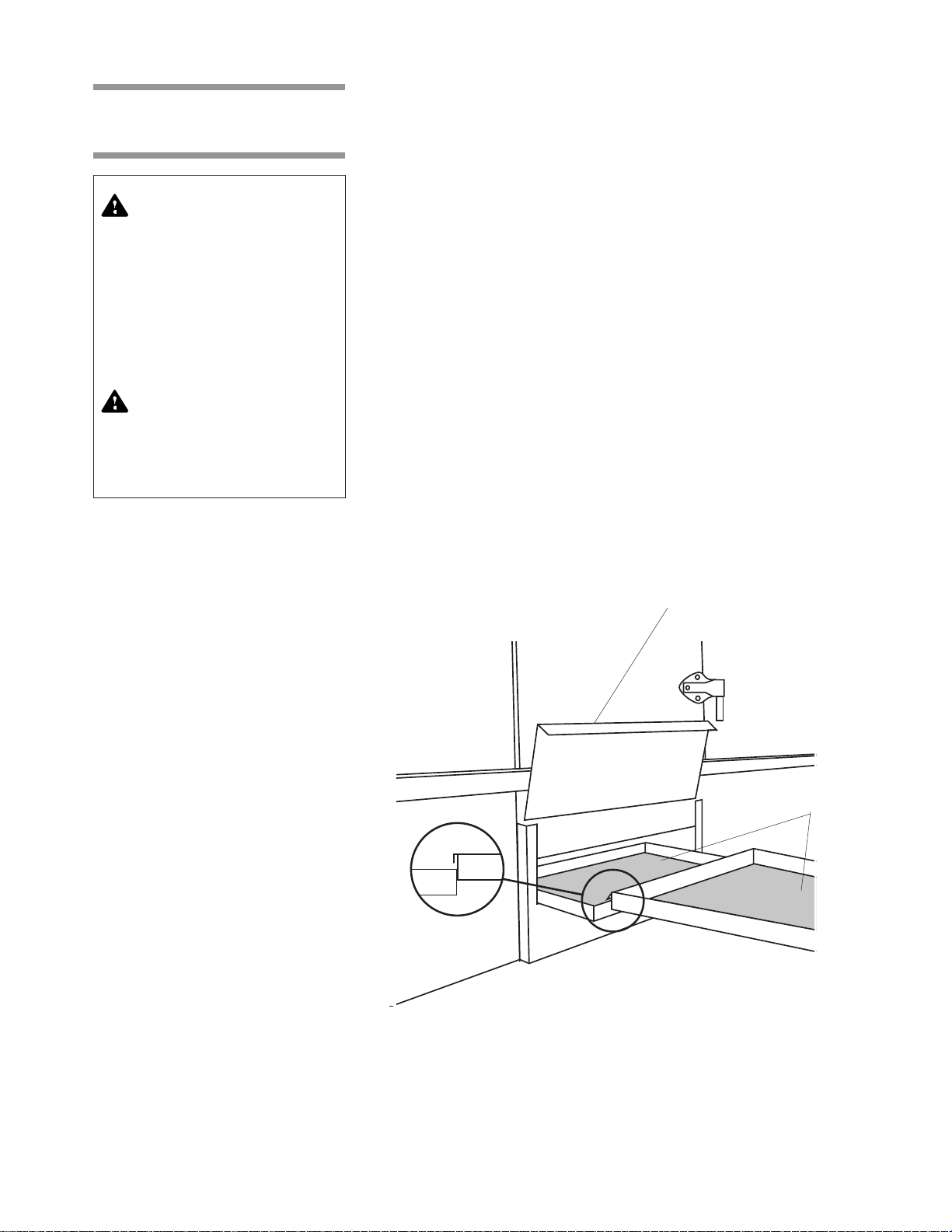
6.3 Daily Cleaning Procedures
• Chamber Solution Screen
NOTE: Clean chamber solution screens while they are still wet, before foreign
matter dries.
1. Lock disconnect switch in OFF position and close building supply valves.
WARNING– ELECTRICAL
SHOCK AND/OR BURN
HAZARD: Disconnect all
utilities to washer before
servicing. Do not service the
washer unless all utilities
have been properly locked
out. Always follow local
electrical safety-related
work practice standards.
WARNING– BURN HAZARD:
Before performing any service on the unit, wait until
chamber and piping cool to
room temperature.
2. Remove access panel from side of cabinet section.
3. Slide screens out of chamber and separate screen pieces as they appear
(see Figure 6-1).
4. Remove any debris from screens.
5. Slide screens back into chamber. Ensure screen pieces are hooked
together (see Figure 6-1).
6. Replace access panel and re-energize washer utilities.
• Garb-el (Option)
After each day of use, run Garb-el for several minutes until both the feed hopper
and the grinding chamber are clear of waste material. This procedure flushes
out the sewer line.
In addition, wash down hopper interior using a few pails of water or a hose.
Disinfectants may be used. Ensure to use disinfectants that will not damage
metal or stainless steel.
Screen Access Panel
Chamber Solution
Screens
Figure 6-1. Two-Piece Solution Screen
6-5
Routine Maintenance Operator Manual 122993-622

6.4 Weekly Cleaning Procedures
6.4.1 Clean Washer Interior
WARNING– CHEMICAL
BURN AND/OR EYE INJURY
HAZARD: Detergents are
caustic and can cause adverse effects to exposed tissues. Do not get in eyes, on
skin, or attempt to swallow.
Read and follow the precautions and instructions on
the detergent label and in
the Material Safety Data
Sheet (MSDS) prior to handling the detergent, refilling
the detergent container, or
servicing the detergent injection pump. Wear appropriate Personal Protective
Equipment (PPE) whenever
handling the detergent or
servicing the detergent injection pump and lines.
WARNING – SLIPPING
HAZARD: To avoid slippery
floor conditions, immediately wipe up any spilled liquids or drippage. If spilled
liquids or drippage are detergents or other chemicals,
follow safety precautions
and handling procedures set
forth on detergent or chemical label and/or Material
Safety Data Sheet (MSDS).
CAUTION – POSSIBLE
EQUIPMENT DAMAGE: Use
nonabrasive cleaners when
cleaning unit. Follow directions on containers and rub
in a back-and-forth motion
(in same direction as surface
grain). Abrasive cleaners will
damage stainless steel.
Cleaners rubbed in a circular
motion or applied with a wire
brush or steel wool will
scratch and dull stainless
steel. Do not use these cleaners on painted surfaces.
1. Wash chamber using a mild detergent solution.
2. Rinse with tap water and dry with a lint-free cloth.
3. If interior is stained, use a general purpose cleaner to remove general
stains or a stainless-steel stain remover for stubborn stains, as follows:
a. Using a damp cloth or sponge, apply cleaner in a back and forth
motion, in same direction as surface grain.
b. Thoroughly wipe off cleaner.
c. Polish surface with a clean, dry, and lint-free cloth.
6-6
122993-622 Operator Manual Routine Maintenance

6.4.2 Clean Spray Jets and Headers
WARNING– ELECTRICAL
SHOCK AND/OR BURN
HAZARD: Disconnect all
utilities to washer before
servicing. Do not service the
washer unless all utilities
have been properly locked
out. Always follow local
electrical safety-related
work practice standards.
WARNING– BURN HAZARD:
Before performing any service on the unit, wait until
chamber and piping cool to
room temperature.
WARNING – SLIPPING
HAZARD: To avoid slippery
floor conditions, immediately wipe up any spilled
liquids or drippage. If
spilled liquids or drippage
are detergents or other
chemicals, follow safety
precautions and handling
procedures set forth on
detergent or chemical label
and/or Material Safety Data
Sheet (MSDS).
1. Lock disconnect switch in OFF position and close building supply valves.
2. Remove top and bottom spray headers one at a time (see Figure 6-2). Lift
header up until locator pins clear positioning holes and pull header out of
O-ring connector.
3. Insert a wire (smaller diameter than a jet nozzle) into those spray jet nozzles
that appear clogged, and push debris through nozzles into header.
NOTE: Jet nozzles are factory aligned to provide maximum washing
efficiency. Do not move the spray jets when cleaning.
4. Remove plug from end of header and rinse header under running water to
clean out debris.
5. Replace plug and reinstall header in proper location. Ensure header is
pushed into O-ring connector and each locator pin is seated in its proper
hole.
NOTE: Locator pins are aligned with specific positioning holes. Do not force
header into incorrect positioning holes.
6. Re-energize washer utilities.
Top Spray
Header
Spray
Jets
Balancing
Valve
Bottom Spray
Header
Figure 6-2. Spray Header Removal
6-7
Routine Maintenance Operator Manual 122993-622

6.5 Monthly
Cleaning Procedure
NOTE: Depending on the hardness of water being used, it may be necessary
to remove hard water deposits more often. Remove deposits from chamber and
material handling accessories whenever deposits become visible.
6.5.1 Remove Hard Water
Deposits From Chamber
and Accessories
WARNING– CHEMICAL
BURN AND/OR EYE INJURY
HAZARD: Detergents are
caustic and can cause adverse effects to exposed
tissues. Do not get in eyes,
on skin, or attempt to swallow. Read and follow the
precautions and instructions on the detergent label
and in the Material Safety
Data Sheet (MSDS) prior to
handling the detergent, refilling the detergent container, or servicing the detergent injection pump.
Wear appropriate Personal
Protective Equipment
(PPE) whenever handling
the detergent or servicing
the detergent injection
pump and lines.
1. If desired, place empty accessory rack in chamber.
2. Turn off detergent supply pump (by others).
3. Pour one quart of descaling liquid into chamber sump and close door.
4. Press MANUAL MENU touch pad to access Manual Control mode.
5. Select and start PUMP/DRIVE function.
6. Let washer run for 15 minutes, then press STOP/RESET touch pad.
7. Once hard water deposits are removed, select and start DRAIN function
to drain descaler solution from sump (see
8. Manually fill and drain chamber sump again to remove any residue.
9. Press STOP/RESET touch pad to exit Manual Control mode and turn on
detergent supply pump.
Section 4.7.3, Tank Dump
).
WARNING – SLIPPING
HAZARD: To avoid slippery
floor conditions, immediately wipe up any spilled
liquids or drippage. If
spilled liquids or drippage
are detergents or other
chemicals, follow safety
precautions and handling
procedures set forth on
detergent or chemical label
and/or Material Safety Data
Sheet (MSDS).
6-8
122993-622 Operator Manual Routine Maintenance

6.5.2 Clean Building
Supply-Line Strainers
WARNING– ELECTRICAL
SHOCK AND/OR BURN
HAZARD: Disconnect all
utilities to washer before
servicing. Do not service the
washer unless all utilities
have been properly locked
out. Always follow local
electrical safety-related
work practice standards.
WARNING– BURN HAZARD:
• Before performing any service on the unit, wait until
chamber and piping cool to
room temperature.
• Pipes may be extremely hot.
NOTE: Piping tools are required. Contact facility maintenance technician.
1. Set POWER-OFF/STANDBY switch to OFF/STANDBY. Lock disconnect
switch in OFF position and close building supply valves.
2. Remove hex caps from each strainer body.
3. Pull out strainer screen from body.
4. Using a wire brush or steel wool, scrape all rust and residue from strainer
screen and body. Ensure all perforations are clear, by poking open with a
wire. Replace screen if damaged or corroded.
5. Verify no dirt or other particles remain in strainer body and insert screen
into strainer body.
6. Using pipe joint sealing compound, replace and tighten hex cap.
7. Verify all pipe connections are tight and leak free after reassembly.
8. Re-energize washer utilities.
6.5.3 Clean Wash
Temperature Control
Probe
WARNING– CHEMICAL
BURN AND/OR EYE INJURY
HAZARD: Detergents are
caustic and can cause adverse effects to exposed
tissues. Do not get in eyes,
on skin, or attempt to swallow. Read and follow the
precautions and instructions on the detergent label
and in the Material Safety
Data Sheet (MSDS) prior to
handling the detergent, refilling the detergent container, or servicing the detergent injection pump.
Wear appropriate Personal
Protective Equipment
(PPE) whenever handling
the detergent or servicing
the detergent injection
pump and lines.
1. Lock disconnect switch in OFF position and close building supply valves.
2. Lower water level in wash recirculating tank to below probe opening.
3. Loosen compression fitting nut and remove probe from recirculating tank.
4. Using a rag dampened with acid or descaler, remove hard water deposits
from probe.
5. Reinstall probe and tighten compression fitting nut.
6. Re-energize washer utilities.
WARNING– ELECTRICAL
SHOCK AND/OR BURN
HAZARD: Disconnect all
utilities to washer before
servicing. Do not service the
washer unless all utilities
have been properly locked
out. Always follow local
electrical safety-related
work practice standards.
WARNING– BURN HAZARD:
Before performing any service on the unit, wait until
chamber and piping cool to
room temperature.
6-9
Routine Maintenance Operator Manual 122993-622

6.5.4 Clean Rinse
Temperature Control
Probes
WARNING– ELECTRICAL
SHOCK AND/OR BURN
HAZARD: Disconnect all
utilities to washer before
servicing. Do not service the
washer unless all utilities
have been properly locked
out. Always follow local
electrical safety-related
work practice standards.
WARNING– BURN HAZARD:
Before performing any service on the unit, wait until
chamber and piping cool to
room temperature.
WARNING– CHEMICAL
BURN AND/OR EYE INJURY
HAZARD: Detergents are
caustic and can cause adverse effects to exposed
tissues. Do not get in eyes,
on skin, or attempt to swallow. Read and follow the
precautions and instructions on the detergent label
and in the Material Safety
Data Sheet (MSDS) prior to
handling the detergent, refilling the detergent container, or servicing the detergent injection pump.
Wear appropriate Personal
Protective Equipment
(PPE) whenever handling
the detergent or servicing
the detergent injection
pump and lines.
1. Lock disconnect switch in OFF position and close building supply valves.
2. Lower water level in rinse recirculating tank to below probe opening.
3. Loosen compression fitting nut and remove probe from recirculating tank.
4. Using a rag dampened with acid or descaler, remove hard water deposits
from probe.
5. Reinstall probe and tighten compression fitting nut.
6. Re-energize washer utilities.
6-10
122993-622 Operator Manual Routine Maintenance

6.5.5 Clean Water Level Sensing Probes
1. Lock disconnect switch in OFF position and close building supply valves.
2. Remove wires from each of two probes in wash and rinse recirculating
tanks.
WARNING– ELECTRICAL
SHOCK AND/OR BURN
HAZARD: Disconnect all
utilities to washer before
servicing. Do not service the
washer unless all utilities
have been properly locked
out. Always follow local
electrical safety-related
work practice standards.
WARNING– BURN HAZARD:
Before performing any service on the unit, wait until
chamber and piping cool to
room temperature.
WARNING– CHEMICAL
BURN AND/OR EYE INJURY
HAZARD: Detergents are
caustic and can cause adverse effects to exposed
tissues. Do not get in eyes,
on skin, or attempt to swallow. Read and follow the
precautions and instructions on the detergent label
and in the Material Safety
Data Sheet (MSDS) prior to
handling the detergent, refilling the detergent container, or servicing the detergent injection pump.
Wear appropriate Personal
Protective Equipment
(PPE) whenever handling
the detergent or servicing
the detergent injection
pump and lines.
NOTE: Make note of wire locations for reassembly. Reversing wires can
cause washer to malfunction.
3. Lower water level in each tank below probe openings.
4. Remove probes. Using a rag dampened with acid or descaler, remove
hard water deposits from each probe.
5. Reinstall probes and attach wires in original positions.
6. Re-energize washer utilities.
6-11
Routine Maintenance Operator Manual 122993-622

6.6 Changing Printer Paper Roll
See Figure 6-3.
NOTE: Do not operate printer without paper.
1. Open printer door.
2. Grasp remaining paper and pull it upward and out of printer.
3. Remove take-up spindle from its drive mechanism by pulling it to left.
4. Remove paper roll from take-up spindle and set empty take-up spindle
aside.
5. Lower platen and remove lower paper spindle by pulling it straight forward.
6. Place new paper roll onto lower spindle with paper feeding downward from
back of paper roll.
NOTE: Verify paper roll is positioned correctly. Thermal printer does not
print if the paper roll is inserted backwards. Use only STERIS thermal paper
(P129359-008). Damage to printer mechanism can occur if paper of
different width or thickness is used.
7. Place lower spindle (with new paper roll) back into position by pressing
from front until it snaps into place.
8. Pull four or five inches of paper out from roll and tear corners off end.
9. Slide tab of paper roll into printer from back (with platen still in down
position) until it exits from front of printer.
10. Grasp tab of paper, pull up 10 to 12 inches of paper, and feed this paper
through opening in platen.
11. Insert tab of new paper roll into slot of take-up spindle and rotate spindle
to secure paper in slot.
12. Raise platen back up into position and snap in place under catch.
13. Press take-up spindle back onto drive mechanism and allow motor to
rotate spindle to verify paper is secured to take-up roll.
14. Set POWER-OFF/STANDBY switch to OFF/STANDBY position then to
POWER to verify paper is correctly routed into mechanism and printer
prints. Printer does not print if thermal paper was placed on wrong side.
15. Close printer door.
6-12
122993-622 Operator Manual Routine Maintenance
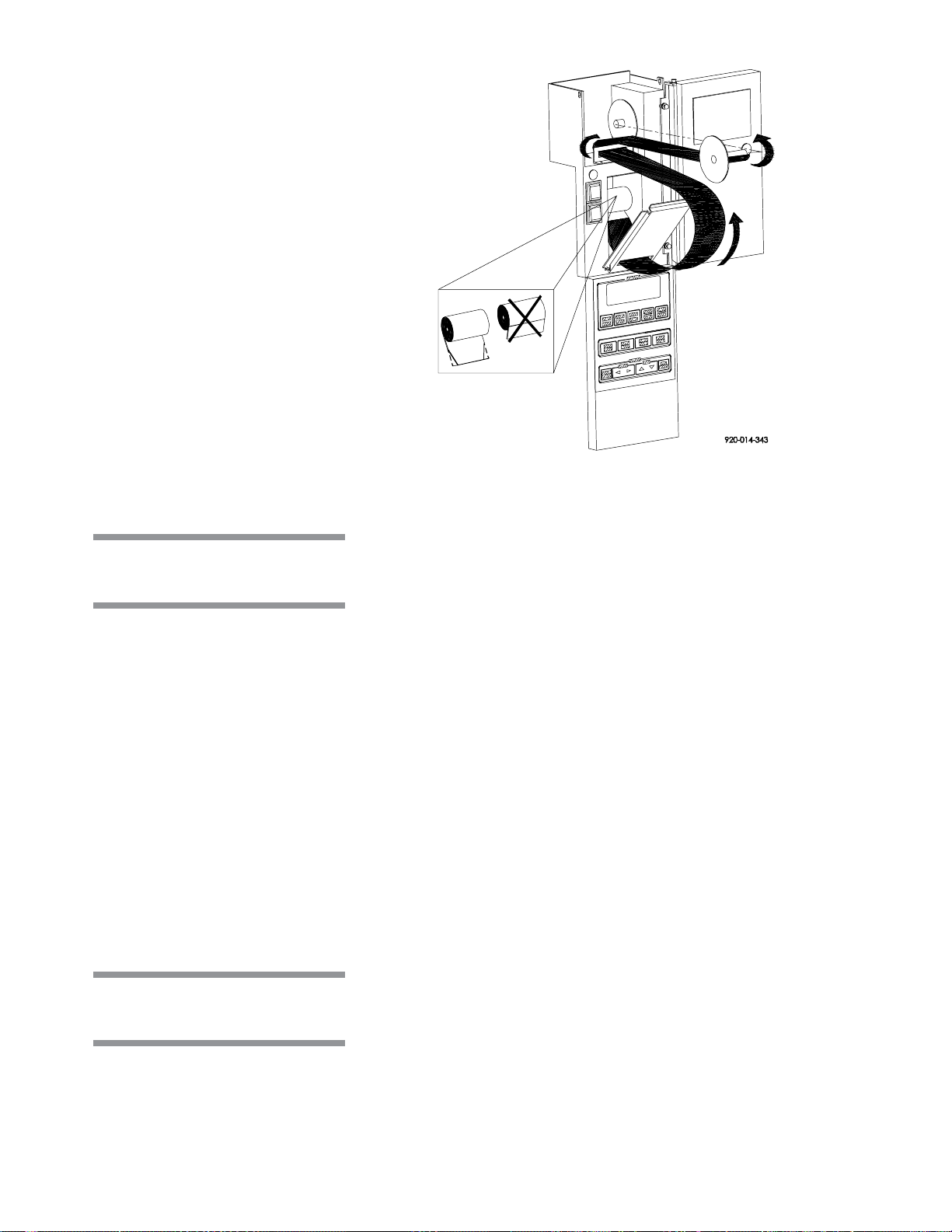
6.7 Storing Thermal Paper
YES NO
Figure 6-3. Changing Printer Paper Roll
Thermal paper is subject to fading with time, humidity, and exposure to light.
It is the manufacturer's recommendation that thermal paper be stored in a dark
place with an average ambient temperature of less than 77 °F (25 °C) and a
relative humidity less than 65%. Under these conditions, the paper remains
readable for at least five years. It is recommended that if the printed data is to
be retained for periods of time longer than five years (6 to 25 years), an
additional photocopy should be made for record retention. In any case, a
duplicate set of records should be maintained in the files of the engineering or
maintenance departments.
Thermal paper begins to develop color at about 158 °F (70 °C), however,
under humid conditions, it might begin to develop at an accelerated rate. If
stored for 24 hours at 140 °F (60 °C), the paper will show some signs of
development. It will also show signs of development if stored for 24 hours at
113 °F (45 °C) and a relative humidity of 90%.
Do not store thermal paper next to other chemically treated papers - such as
pressure sensitive paper or other type of recording round charts - as this may
cause fading in print. If thermal paper is to be stored in the same area, always
ensure it and other chemically treated papers are kept in separate envelopes.
Thermal paper discolors when exposed to direct sunlight.
(Automatic Detergent Injection System)
6.8 Replace
1. Lift supply hose and low level sensor out of detergent container.
Detergent Container
2. Replace detergent container.
3. Insert supply hose and low level sensor in new detergent container.
IMPORTANT:
detergent container.
Routine Maintenance Operator Manual 122993-622
Ensure supply and low level sensor are inserted in proper
6-13

6.9 Replace
Detergent Squeeze
Tube
(Automatic Detergent Injection System)
IMPORTANT:
pump at a time.
1. Set POWER-OFF/STANDBY switch to OFF/STANDBY. Lock disconnect
switch in OFF position and close building supply valves.
2. Locate detergent supply pump.
It is recommended to disconnect and reconnect one detergent
WARNING– CHEMICAL
BURN AND/OR EYE INJURY
HAZARD: Detergents are
caustic and can cause adverse effects to exposed
tissues. Do not get in eyes,
on skin, or attempt to swallow. Read and follow the
precautions and instructions on the detergent label
and in the Material Safety
Data Sheet (MSDS) prior to
handling the detergent, refilling the detergent container, or servicing the detergent injection pump.
Wear appropriate Personal
Protective Equipment
(PPE) whenever handling
the detergent or servicing
the detergent injection
pump and lines.
CAUTION – POSSIBLE
EQUIPMENT DAMAGE:
When choosing a detergent, select one with a low
chloride content. Detergents with a high chloride
content can corrode stainless steel.
3. Remove clamps and disconnect supply and injection hoses from squeeze
tube (see Figure 6-4).
4. Remove screws from pump cover and lift off pump cover.
5. Grasp one end of squeeze tube and pull tube out of pump. Discard tube.
6. Clean all pump surfaces.
7. Lubricate new squeeze tube (P117950-583). Liberally apply lubricant
(P117950-599) over tube surface to within two inches of each end.
8. Insert one end of squeeze tube into pump. Feed tube through pump by
manually rotating roller block.
9. Spread lubricant over rollers in roller block.
10. Replace pump cover and fasten with screws previously removed.
11. Connect supply and injection hoses to ends of squeeze tube and attach
clamps.
IMPORTANT:
Ensure supply and injection hoses are connected to proper
detergent pump (squeeze tube).
12. Re-energize washer utilities.
NOTE: Detergent supply pump automatically primes once energized.
Ensure proper pump is priming.
Pump
Cover
Roller
Block
Squeeze
Tube
Supply and
Injection Hoses
Figure 6-4. Detergent Supply Pump
6-14
122993-622 Operator Manual Routine Maintenance

6.10 Replace
Cabinet Door Gasket
WARNING – PERSONAL
INJURY AND/OR EQUIPMENT DAMAGE HAZARD:
Repairs and adjustments to
this equipment must be
made only by STERIS or
STERIS-trained service personnel. Nonroutine maintenance performed by unqualified personnel or installation of unauthorized
parts could cause personal
injury, result in improper
equipment performance,
void the warranty, or result
in costly damage. Contact
STERIS regarding service
options.
1. Lock disconnect switch in OFF position and close building supply valves.
2. With cabinet access door open, remove old gasket from around door
opening (see Figure 6-5).
3. Insert new gasket on door lip of chamber door frame.
4. Starting at top center of door opening, press gasket in place. Work gasket
around entire opening, pressing and smoothing gasket as it is installed.
5. When gasket is completely installed around metal lip, overlap installed
gasket, with remaining gasket, by three inches and cut off the excess.
6. Starting at top center, press and smooth gasket again.
7. Re-energize washer utilities.
WARNING– ELECTRICAL
SHOCK AND/OR BURN
HAZARD: Disconnect all
utilities to washer before
servicing. Do not service the
washer unless all utilities
have been properly locked
out. Always follow local
electrical safety-related
work practice standards.
Metal Lip
Door Gasket
Figure 6-5. Replace Door Gasket
6-15
Routine Maintenance Operator Manual 122993-622
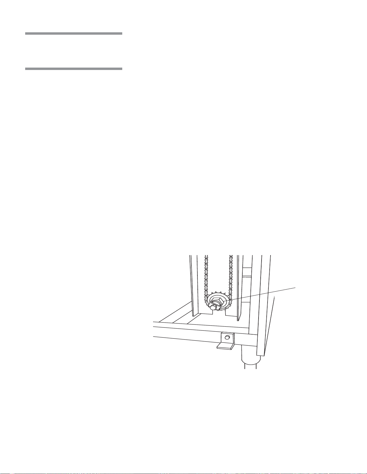
6.11 Adjust
Conveyor Drive
Clutch
1. If washer is running, press STOP/RESET touch pad.
2. Open cabinet access doors and verify nothing is blocking conveyor
movement. Close access doors.
3. Start conveyor belt by turning on manual drive system power switch,
located on back of electrical control box.
4. From unload-end control panel, push drive system EMERGENCY STOP
pushbutton (see Figure 4-3).
5. Lock disconnect switch in OFF position and close building supply valves.
6. Remove chain guard to access drive motor gear reducer (see Figure 6-6).
7. Loosen Allen head setscrews on adjusting nut.
8. Torque adjusting nut to 65 ft/lb (average setting).
9. Tighten setscrews and reinstall chain guard.
10. Re-energize washer utilities.
11. Pull out drive system EMERGENCY STOP pushbutton and verify correct
adjustment. When correctly adjusted, drive clutch will disengage and stop
belt movement if the conveyor belt is obstructed.
If conveyor belt slips, repeat procedure and increase torque setting by 5lb.
Increments until satisfied with adjustment.
Adjusting Nut
Figure 6-6. Conveyor Drive Clutch
6-16
122993-622 Operator Manual Routine Maintenance
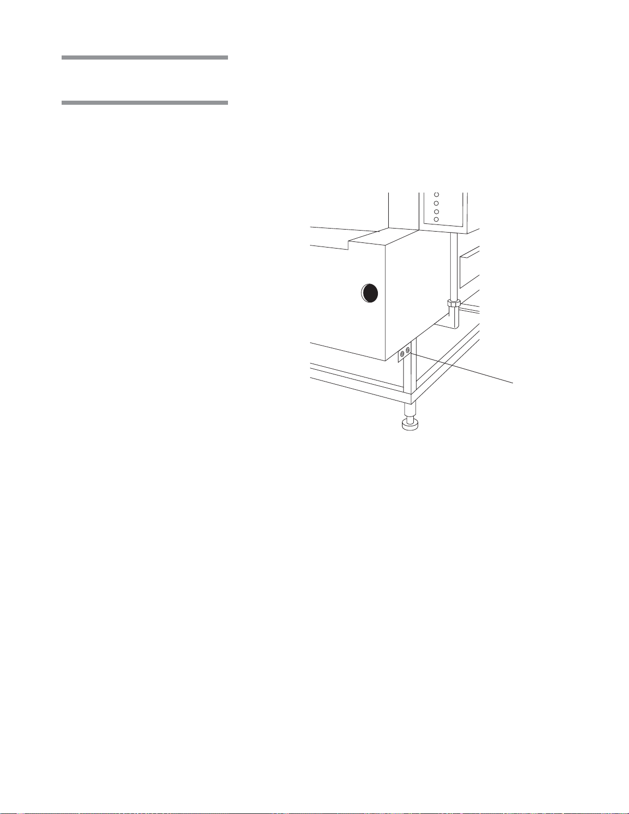
6.12 Grease
Conveyor Bearings
Conveyor bearings must be greased twice a year as follows:
1. Locate conveyor grease fittings, two at each end of washer (see Fig-
ure 6-7).
2. Apply a high temperature molybdenum grease.
Conveyor
Grease Fittings
(Load-End)
Figure 6-7. Conveyor Grease Fittings
6-17
Routine Maintenance Operator Manual 122993-622

6.13 Final Rinse
Temperature
Controls
The final rinse water temperature can be controlled manually by regulating the
flow of steam and hot water through the final rinse heat exchanger.
Adjust final rinse water temperature between 185 and 195 °F (85 and 91 °C)
as follows:
1. If washer is running, press STOP/RESET touch pad.
2. Completely close steam throttling valve and open fully final rinse water
throttling valve (see Figure 6-8).
3. If necessary, allow solution/water in recirculating tanks to reach set
temperatures.
4. Press CYCLE START touch pad.
5. Verify reading on heat exchanger temperature gauge. Gauge indicates
temperature of final rinse water after water passes through heat exchanger.
6. Slowly open steam throttling valve until temperature gauge reads desired
temperature.
7. If gauge does not reach desired temperature after steam throttling valve
is fully open, slowly close final rinse water throttling valve until desired
temperature is reached.
IMPORTANT
: Final rinse water flow must be re-balanced if the final rinse
water throttling valve is adjusted (closed) while setting the final rinse water
temperature.
Final Rinse Water Throttle
Valve
Optional Dryer Steam
Throttle Valve
Heat Exchanger
Temperature Gauge
Steam Throttling Valve
Figure 6-8. Final Rinse Temperature Controls
6-18
122993-622 Operator Manual Routine Maintenance

6.14 Balance Final Rinse Water Flow
WARNING – PERSONAL
INJURY AND/OR EQUIPMENT DAMGE HAZARD:
Repairs and adjustments to
this equipment must be
made only by STERIS or
STERIS-trained service personnel. Nonroutine maintenance performed by unqualified personnel or installation of unauthorized
parts could cause personal
injury, result in improper
equipment performance,
void the warranty, or result
in costly damage. Contact
STERIS regarding service
options.
WARNING– ELECTRICAL
SHOCK AND/OR BURN
HAZARD: Disconnect all
utilities to washer before
servicing. Do not service the
washer unless all utilities
have been properly locked
out. Always follow local
electrical safety-related
work practice standards.
WARNING– BURN HAZARD:
• Before performing any service on the unit, wait until
chamber and piping cool to
room temperature.
1. Completely close pre-wash and wash tap valves (see Figure 6-9).
2. Ensure manual wash and rinse drain valves are closed.
3. Using a pipe wrench, remove observation caps from wash and rinse drain
spouts (see Figure 6-10).
4. Press CYCLE START touch pad.
5. Observe wash and rinse overflows. At this time, there should be no
overflow from wash section. Rinse section should be generating a heavy
overflow.
6. Adjust wash water level as follows:
a.Fully open wash tap valve. Once overflow is observed, completely close
valve then reopen valve one turn (360°) only.
b.Allow washer to run for three minutes while observing wash overflow.
c.If wash section generates a small overflow (trickle), adjustment is
correct. If a heavy overflow is produced, partially close the wash tap
valve. If no overflow exists, open tap valve in 1/4-turn increments until
correct overflow is observed.
NOTE: After each adjustment, allow washer to run for three minutes and
recheck overflow.
7. Adjust pre-wash water spray as follows:
a.Open pre-wash tap valve two turns.
b.Carefully observe pre-wash spray by opening neoprene curtain on load
end.
c.Pre-wash spray is adjusted correctly if bottom jets spray water up to
twelve inches higher than conveyor belt. If water is sprayed out of
chamber, partially close pre-wash tap valve. If water is not sprayed high
enough (twelve inches above conveyor belt), open tap valve in one turn
increments until correct spray is obtained.
8. Allow washer to run for ten minutes.
9. Observe wash and rinse overflows. At this time, wash section should be
generating a small overflow (trickle) and rinse section should be generating at least a small overflow. If no overflow exists from rinse section,
decrease pre-wash water spray.
• Pipes may be extremely hot.
6-19
Routine Maintenance Operator Manual 122993-622
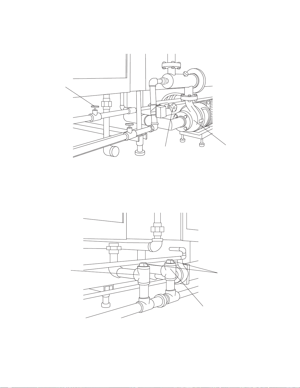
Pre-Wash Tap Valve
Wash Drain Spout
Wash Tap Valve
Figure 6-9. Close Pre-Wash and Wash Tap Valves
Wash Treatment Pump
Observation
Caps
Rinse Drain Spout
Figure 6-10. Observation Caps
6-20
122993-622 Operator Manual Routine Maintenance
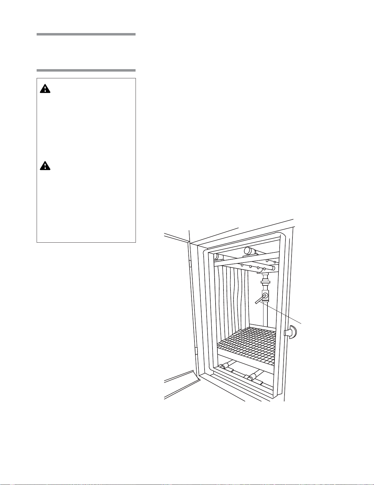
6.15 Adjust
Hydraulic Hold-Down
System
WARNING– ELECTRICAL
SHOCK AND/OR BURN
HAZARD: Disconnect all
utilities to washer before
servicing. Do not service the
washer unless all utilities
have been properly locked
out. Always follow local
electrical safety-related
work practice standards.
WARNING– BURN HAZARD:
• Before performing any service on the unit, wait until
chamber and piping cool to
room temperature.
• Do not adjust balancing
valve while washer is operating.
Hydraulic hold-down system allows manual control of the solution/water
pressure exiting the spray jet systems during cycle operation. The water
pressure to the upper and lower spray jets can be controlled by adjusting the
balancing valves, located inside the wash and rinse chambers.
1. During unit operation, observe items as they appear at unload end of
washer.
2. If items are flipped from original loading position, adjust balancing valves
as follows:
a.Press STOP/RESET touch pad.
b.Open wash and rinse cabinet access doors.
c. Locate balancing valves, usually a two-inch ball valve with a blue handle
(see Figure 6-11).
d.Slowly turn wash and rinse valve handles up toward horizontal position
to reduce water pressure to lower spray jets.
e.Close cabinet doors.
3. Load items on conveyor and press CYCLE START touch pad. Observe
items as they appear at unload end of washer.
4. If items are still flipping, repeat Steps 2 and 3 until satisfied with adjust-
ment.
• Pipes may be extremely hot.
Balancing
Valve
Figure 6-11. Balancing Valve Location (Typical)
6-21
Routine Maintenance Operator Manual 122993-622
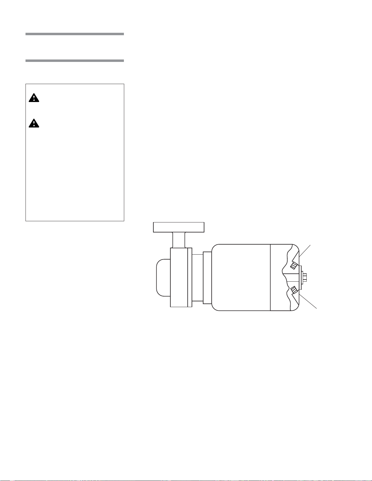
6.16 Lubricate Pump Motor
WARNING – BURN HAZARD: Pipes may be extremely hot.
WARNING – SLIPPING
HAZARD: To avoid slippery
floor conditions, immediately wipe up any spilled
liquids or drippage. If
spilled liquids or drippage
are detergents or other
chemicals, follow safety
precautions and handling
procedures set forth on
detergent or chemical label
and/or Material Safety Data
Sheet (MSDS).
Pump motor must be lubricated once a year. When necessary, grease can be
completely renewed by forcing out old grease with new grease.
1. If possible, place a pan under motor to catch old grease.
NOTE: Motor should be lubricated while warm.
2. Thoroughly wipe off housing around fill and drain plugs.
3. Remove fill and drain plugs (see Figure 6-12). Clear drain hole of any
hardened grease which may have accumulated.
NOTE: Depending on model and year of pump, motor may be equipped with
one or two grease fittings. If motor is not provided with grease fittings, no
lubrication is necessary.
4. Using a low pressure grease gun, add recommended grease through fill
hole until it starts to come out of drain hole.
NOTE: Use only fresh, uncontaminated lubricant.
5. Run motor for ten to twenty minutes to expel any excess grease.
6. Thoroughly clean the fill and drain plugs before replacing them.
Figure 6-12. Lubricate Pump Motor
Fill Plug
Drain Plug
6-22
122993-622 Operator Manual Routine Maintenance

6.17 Inspect and
Clean Self-Cleaning
Filter
Self-cleaning screen must be inspected and manually cleaned once a month.
1. Lock disconnect switch in OFF position and close building supply valves.
2. Remove three bolts and loosen fourth on vertical plate directly above
pump (see Figure 6-13).
3. Move plate to one side and remove Teflon gasket.
WARNING– ELECTRICAL
SHOCK AND/OR BURN
HAZARD: Disconnect all
utilities to washer before
servicing. Do not service the
washer unless all utilities
have been properly locked
out. Always follow local
electrical safety-related
work practice standards.
WARNING– BURN HAZARD:
• Before performing any service on the unit, wait until
chamber and piping cool to
room temperature.
• Do not adjust balancing
valve while washer is operating.
• Pipes may be extremely hot.
4. Remove screen by pulling straight out on handle (see Figure 6-13).
5. Rinse screen to remove any debris and inspect for damage.
6. Carefully reinsert screen in assembly housing and replace gasket. Reposition plate over gasket and evenly tighten all four bolts.
NOTE: The gasket should last for several inspection procedures. When
necessary, order replacement gasket (P764324-398) from STERIS.
7. Re-energize washer utilities.
Vertical Plate
Screen
Assembly
Housing
Handle
Figure 6-13. Self-Cleaning Screen Assembly
6-23
Routine Maintenance Operator Manual 122993-622
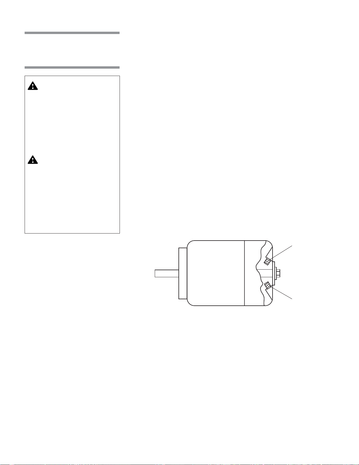
6.18 Lubricate
Blower Motor
(Option)
Blower motor must be lubricated once a year. When necessary, grease can
be completely renewed by forcing out old grease with new grease.
1. If possible, place a pan under motor to catch old grease.
NOTE: Motor should be lubricated while warm.
2. Thoroughly wipe off housing around fill and drain plugs.
WARNING– ELECTRICAL
SHOCK AND/OR BURN
HAZARD: Disconnect all
utilities to washer before
servicing. Do not service the
washer unless all utilities
have been properly locked
out. Always follow local
electrical safety-related
work practice standards.
WARNING– BURN HAZARD:
• Before performing any service on the unit, wait until
chamber and piping cool to
room temperature.
• Do not adjust balancing
valve while washer is operating.
• Pipes may be extremely hot.
3. Remove fill and drain plugs (see Figure 6-14). Clear drain hole of any
hardened grease which may have accumulated.
NOTE: Depending on model and year of blower, motor may be equipped
with one or two grease fittings. If motor is not provided with grease fittings,
no lubrication is necessary.
4. Using a low pressure grease gun, add recommended grease through fill
hole until it starts to come out of drain hole.
NOTE: Use only fresh, uncontaminated lubricant.
5. Run motor for ten to twenty minutes to expel any excess grease.
6. Thoroughly clean fill and drain plugs before replacing them.
Fill Plug
Drain Plug
Figure 6-14. Blower Motor
6-24
122993-622 Operator Manual Routine Maintenance

6.19 Adjust Dryer
Temperature
Controls (Dryer
Section Option)
Temperature of recirculated hot air is adjustable up to 210 °F (99 °C) by
controlling the amount of steam supplied to the radiator (see Figure 6-15).
1. To increase temperature, turn steam valve counter-clockwise.
2. To decrease temperature, turn steam valve clockwise.
A temperature gauge is provided to monitor air temperature.
Balanced Dial
Steam Handling Valves
(Dual Radiator System)
6.20 Belt Speed Control
Figure 6-15. Dryer Temperature Control
Conveyor belt speed can be adjusted using the adjustable belt speed dial,
located on the back of the electrical control box (see Figure 6-16).
Adjustment is made by turning dial towared low or high, to select desired
speed. Belt speed is variable from two to ten feet per minute.
DRIVE SYSTEM
STOP
LOW HIGH
ADJUSTABLE BELT SPEED
Proximity
Switch By-Pass
ON
OFF
Figure 6-16. Drive System Control
6-25
Routine Maintenance Operator Manual 122993-622

TROUBLESHOOTING
IMPORTANT: A listing of the Safety Precautions to be observed when operat-
WARNING – PERSONAL
INJURY AND/OR EQUIPMENT DAMGE HAZARD:
Repairs and adjustments to
this equipment must be
made only by STERIS or
STERIS-trained service personnel. Nonroutine maintenance performed by unqualified personnel or installation of unauthorized
parts could cause personal
injury, result in improper
equipment performance,
void the warranty, or result
in costly damage. Contact
STERIS regarding service
options.
WARNING– ELECTRICAL
SHOCK AND/OR BURN
HAZARD: Disconnect all
utilities to washer before
servicing. Do not service the
washer unless all utilities
have been properly locked
out. Always follow local
electrical safety-related
work practice standards.
ing and servicing this equipment can be found in Section 1 of this manual. Do
not operate or service the equipment until you have become familiar with this
information.
This section contains detailed information on the types of washer malfunctions
likely to occur, and possible causes and corrective actions.
If you are unable to correct the problem with use of the following Troubleshooting Charts, or if a problem occurs that is not described on the charts, please
call STERIS. A factory-trained technician will promptly place your washer in
proper working condition.
NOTE: Never allow unqualified persons to service the washer.
7
WARNING– BURN HAZARD:
• Before performing any service on the unit, wait until
chamber and piping cool to
room temperature.
• Pipes may be extremely hot.
7-1
Troubleshooting Operator Manual 122993-622

Table 7-1. Troubleshooting Chart
PROBLEM POSSIBLE CAUSE AND/OR CORRECTION
1. No power.
2. Washer does not start.
3. Washer does not stop.
1. Building electrical supply disconnect switch (circuit breaker) to OFF
position. Position switch to ON.
2. Incomplete or loose electrical connection. Inspect all wiring connections. Complete or tighten as necessary.
3. Fuse in power supply failed. Replace fuse.
4. Power supply failed. Replace power supply.
5. Power switch failed. Replace power switch.
1. POWER-OFF/STANDBY switch to POWER.
2. Hot water supply valve closed. Open water supply valve.
3. Water level sensing probe malfunction. Verify operation. Clean or
replace as necessary.
4. Building supply-line strainers clogged. Clean strainers.
5. Incomplete or loose electrical connection. Inspect all wiring connections. Complete or tighten as necessary.
6. Blown fuse. Replace fuse.
Manual drive system or optional dryer system power switches on.
Turn manual switches off.
4. Insufficient or no spray volume
generated through wash and
rinse spray jets.
1. Spray jets clogged. Clean spray jets and headers.
2. Spray header plugs missing. Replace plugs.
3. Self-cleaning screen clogged. Remove debris from screen.
4. Loose hose connection on pump suction pick-up pipe. Tighten hose
clamps or replace as necessary.
5. Water level sensing probe malfunction. Verify operation. Clean or
replace as necessary.
5. Insufficient or no spray volume
generated through final rinse
spray jets.
1. Supply valves not fully open. Open building and washer supply
valves.
2. Spray jets clogged. Clean spray jets and headers.
3. Spray header plugs missing. Replace plugs.
4. Building supply-line strainers clogged. Clean strainers.
5. Final rinse water flow incorrectly set. Balance final rinse water flow.
6. Final rinse water solenoid valve fails. Repair or replace as necessary.
7-2
122993-622 Operator Manual Troubleshooting

Table 7-1. Troubleshooting Chart (Cont'd)
PROBLEM POSSIBLE CAUSE AND/OR CORRECTION
6. Too much water entering chamber. Excess amount of water going
to overflow drain.
7. Insufficient water entering chamber.
8. Pump runs with insufficient or no
pump pressure.
1. Water level sensing probe malfunction. Verify operation. Clean or
replace as necessary.
2. Fill solenoid valve remains open. Repair or replace valve as
necessary.
3. Poor electrical connection between water level sensing probe and
control. Inspect connections and tighten if necessary.
1. Hot water supply valve closed. Open water supply valve.
2. Manual drain valve open. Close valve.
3. Water level sensing probe malfunction. Verify operation. Clean or
replace as necessary.
4. Building supply-line strainers clogged. Clean strainers.
1. Water level sensing probe malfunction. Verify operation. Clean or
replace as necessary.
2. Pump suction pick-up pipe clogged. Clean pick-up pipe.
3. Water temperature in excess of 195 °F (91 °C). Lower temperature
set point.
4. Self-cleaning screen clogged. Remove debris from screen.
9. Pump runs with too much pressure.
10. Recirculating tank does not drain
completely.
5. Loose hose connection on pump suction pick-up pipe. Tighten
hose clamps or replace as necessary.
6. Too much soap in wash recirculating tank. Drain wash recirculating tank, refill with fresh water, and decrease detergent injection
rate.
1. Self-cleaning screen clogged. Remove debris from screen.
2. Spray jets clogged. Clean spray jets and headers.
3. Drain line plugged. Flush out line.
1. Drain opening at bottom of recirculating tank plugged. Flush out
drain opening.
2. Drain line plugged. Flush out line.
3. Defective drain valve. Repair or replace as necessary.
7-3
Troubleshooting Operator Manual 122993-622

Table 7-1. Troubleshooting Chart (Cont'd)
PROBLEM POSSIBLE CAUSE AND/OR CORRECTION
11. Low water wash light on.
12. Low water rinse light on.
13. Vapor escaping around door(s).
1. Manual wash drain valve open. Close valve.
2. Too much detergent. Drain wash recirculating tank, refill with fresh
water, and decrease detergent injection rate.
3. Final rinse water flow incorrectly set. Balance final rinse water flow.
4. Water level sensing probe malfunctions. Verify operation. Clean or
replace as necessary.
1. Manual rinse drain valve open. Close valve.
2. Supply valves not fully open. Open building and washer supply
valves.
3. Building supply-line strainers clogged. Clean strainers.
4. Final rinse water flow incorrectly set. Balance final rinse water flow.
5. Water level sensing probe malfunctions. Verify operation. Clean or
replace as necessary.
6. Final rinse water solenoid valve fails. Repair or replace as necessary.
1. Exhaust dampered too much. Adjust dampering system.
2. Exhaust system off. Verify operation.
3. Spray jets misaligned. Realign jets toward load surfaces.
4. Spray header plugs missing. Replace plugs.
14. Water leaks from washer. 1. Cabinet joints leaking. Seal joints where necessary.
2. Cabinet door gasket worn or defective. Replace gasket.
3. Spray jets misaligned. Realign jets away from doors.
4. Piping leaking. Verify hose clamps, valves, and piping. Tighten
connections as necessary.
15. Foam in wash recirculating tank. 1. Detergent is foaming. Use recommended products.
2. Too much detergent injected into wash recirculating tank. Verify
injection rate.
3. Debris collecting in recirculating tank. Drain and refill tank more
often.
7-4
122993-622 Operator Manual Troubleshooting

Table 7-1. Troubleshooting Chart (Cont'd)
PROBLEM POSSIBLE CAUSE AND/OR CORRECTION
16. Items come out dirty. 1. Empty detergent container. Refill or replace container.
2. Incorrect detergent used. Use recommended products.
3. Spray jets clogged. Clean spray jets and headers.
4. Spray header plugs missing. Replace plugs.
5. Too much detergent injected into wash recirculating tank. Verify
injection rate.
6. Spray jets misaligned. Realign jets toward load surfaces.
7. Pump suction pick-up pipe clogged. Clean pick-up pipe.
8. Loose hose connection on pump suction pick-up pipe. Tighten hose
clamps or replace as necessary.
9. Water level sensing probe malfunction. Verify operation. Clean or
replace as necessary.
10. Self-cleaning screen clogged. Remove debris from screen.
11. Temperature set point too low. Raise temperature set point.
12. Drain line plugged. Flush out line.
13. Manual drain valve clogged. Clean valve.
14. Not enough pressure on lower spray jets. Adjust hydraulic hold down
system.
15. Too much steam pressure. Adjust steam throttling valve, at heat
exchanger, to 185 – 195 °F (85 – 91 °C).
16. Not enough final rinse water. Open final rinse water throttling valve,
at heat exchanger, to 185 – 195 °F (85 – 91 °C).
17. Conveyor not moving. 1. Conveyor jammed. Check for obstructions.
2. Drive system EMERGENCY STOP pushbutton pushed in. Pull out
pushbutton.
3. Solution/water temperature below optional temperature guarantee
set point. Allow solution/water in recirculating tanks to reach temperature.
4. Manual drain valve open. Close valve.
5. Poor electrical connection between drive system and control. Inspect connections and tighten if necessary.
6. Water level sensing probe malfunction. Verify operation. Clean or
replace as necessary.
7. Drive clutch loose. Tighten clutch assembly.
8. Blown fuse. Replace fuse.
9. Drive chain broken. Replace chain.
Continued...
7-5
Troubleshooting Operator Manual 122993-622

Table 7-1. Troubleshooting Chart (Cont'd)
PROBLEM POSSIBLE CAUSE AND/OR CORRECTION
17.
(Cont'd)
18. Wash solution not reaching
temperature.
19. Washer overheating.
10. Worn drive gear in reduction gear box. Replace gear.
11. Temperature control probe malfunction. Verify operation. Clean or
replace as necessary.
12. Coveyor stop proximity switch was activated.
1. Steam supply valve closed. Open steam valve.
2. Temperature set point too high. Lower temperature set point.
3. Temperature control probe malfunction. Verify operation. Clean or
replace as necessary.
4. Poor quality steam supply. Provide quality as specified on equipment
drawing.
5. Exhaust damper (provided by customer) open too wide. Adjust
damper position.
6. Steam valve stuck closed. Clean valve. Repair or replace if necessary.
7. Steam strainer clogged. Clean strainer.
1. Water temperature in excess of 195 °F (91 °C). Lower temperature set
point.
20. Final rinse water not heating.
2. Steam valve stuck open. Clean valve. Repair or replace if necessary.
3. Temperature control probe malfunction. Verify operation. Clean or
replace as necessary.
1. Steam supply valve closed. Open steam valve.
2. Steam strainer clogged. Clean strainer.
3. Low dynamic steam pressure. Provide steam at pressure specified
on equipment drawing.
4. Leaking steam unions. Tighten unions.
5. Not enough steam pressure. Adjust steam throttling valve at heat
exchanger.
6. Too much water volume. Adjust final rinse water throttling valve at heat
exchanger.
7. Poor electrical connection between final rinse steam valve and
control. Inspect connections and tighten if necessary.
8. Final rinse steam solenoid valve fails. Repair or replace as necessary.
7-6
122993-622 Operator Manual Troubleshooting

Table 7-1. Troubleshooting Chart (Cont'd)
PROBLEM POSSIBLE CAUSE AND/OR CORRECTION
21. Final rinse water overheating.
22. Recirculating rinse water not
reaching temperature.
23. Items flipping during cycle operation.
1. Too much steam pressure. Adjust steam throttling valve at heat
exchanger.
2. Not enough final rinse water. Open final rinse water throttling valve at
heat exchanger.
3. Final rinse water solenoid valve fails. Repair or replace as necessary.
1. Steam-supply valve closed. Open steam valve.
2. Temperature set point too high. Lower temperature set point.
3. RTD malfunction. Verify operation. Clean or replace as necessary.
4. Poor quality steam supply. Provide quality as specified on equipment
drawing.
5. Exhaust damper (provided by customer) open too wide. Adjust
damper position.
6. Steam strainer clogged. Clean strainer.
7. Steam valve stuck closed. Clean valve. Repair or replace if necessary.
1. Conveyor jammed. Check for obstructions.
2. Too much pressure on lower spray jets. Adjust hydraulic hold-down
system.
24. If drying option is present, items
are not sufficiently dried.
25. If Garb-el option is present,
Garb-el is backing up.
1. Air temperature too low. Adjust steam throttling valves at radiator.
2. Conveyor belt speed too high. Lower belt speed.
3. Steam solenoid valve malfunctions. Verify operation. Repair or replace as necessary.
4. No air recirculation. Verify blower operation. Repair or replace as
necessary.
5. Steam trap dirty. Clean trap.
6. Steam strainer clogged. Clean strainer.
7. Poor quality steam supply. Provide quality as specified on equipment
drawing.
1. Blades on hammermill worn (cannot grind properly). Blades are worn
when cutting edges are rounded. Edges are at 90O angle when new.
2. Hammermill blades are full of rubber bands or plastic.
3. Mill screen holes are worn, elongated, or broken.
4. Verify proper rotation of hammermill.
5. Verify plumbing system is not clogged.
7-7
Troubleshooting Operator Manual 122993-622

Table 7-1. Troubleshooting Chart (Cont'd)
PROBLEM POSSIBLE CAUSE AND/OR CORRECTION
26. If Garb-el option is present,
hammermill is noisy.
27. If Garb-el option is present,
hammermill vibration.
28. If Garb-el option is present,
hammermill is leaking around
shaft.
29. If Garb-el option is present, auger (worn screw) does not turn.
1. Grinder shaft bearings are defective or worn.
2. Blades are broken.
3. Remove belts to ensure noise is not from main motor.
1. Mill out of balance (possibly because of accumulation of rubber bands).
2. Blades are broken.
3. Bent or twisted hammermill blades.
4. Worn hammermill.
Seal(s) defective.
1. Shear pin is broken.
2. Feeder overload switch is kicked out.
3. Defective feeder motor.
4. Defective capacitor (a bad capacitor can also cause a good feeder
motor to run in wrong direction).
5. When installing a new motor, verify fan to ensure it runs freely.
30. If Garb-el option is present, auger (worn screw) drags.
31. If Garb-el option is present, water leaks where auger shaft enters hopper.
Worn feeder bearings.
Faulty seal and/or thrust plate.
7-8
122993-622 Operator Manual Troubleshooting

Table 7-2. Troubleshooting Chart - Alarms and/or Printouts
PROBLEM POSSIBLE CAUSE AND CORRECTION
1.
Display shows:
STOP/RESET touch pad was pressed.
PRESS STOP TO ABORT
OR START TO RESUME
and printout message:
CYCLE PAUSED 00:00:00
2. Display shows:
DRIVE STOPPED
LOAD END
or
DRIVE STOPPED
UNLOAD END
3. Unload end proximity switch has
been tripped. Display shows:
UNLOAD END
FULL
4. Display shows:
TANKS FILLING...
Press CYCLE START
press STOP/RESET
touch pad to resume cycle operation, or
touch pad again to abort cycle operation.
One of EMERGENCY STOP pushbuttons was pushed in.
1. Press ALARM REPLY touch pad to silence buzzer.
2. Pull EMERGENCY STOP pushbutton to resume cycle, or press
STOP/RESET
touch pad twice to abort cycle operation.
Unload end proximity switch has been tripped.
Remove cage from end to silence buzzer and resume operation.
Upon startup of cycle, if all tanks are not full, processing will not start
until they are.
5. Display shows:
TANKS HEATING...
Tank temperature has not reached GUARANTEED set point in
allotted time.
Belt drive stopped and will not resume until GUARANTEED temperature is reached.
6. Display shows:
F. RINSE HEATING...
Final rinse water temperature has not reached GUARANTEED set
point in allotted time.
Belt drive stopped and will not resume until GUARANTEED temperature is reached.
7. Display shows:
BACKFLUSH
8. Display shows:
MAINTENANCE DUE!
Back flush ball valve opening/closing.
Belt drive will stop because spray may not be at full pressure.
Press ALARM REPLY touch pad to silence buzzer.
Call STERIS.*
CALL SERVICE
and printout message:
MAINTENANCE DUE!
* Service charges may be incurred. Consult your warranty for details.
7-9
Troubleshooting Operator Manual 122993-622

Table 7-2. Troubleshooting Chart - Alarms and/or Printouts (Cont'd)
PROBLEM POSSIBLE CAUSE AND CORRECTION
9. Display shows:
ALK. TANK
TOO LONG IN FILL
and printout message:
ALK.
TOO LONG IN FILL
10. Display shows:
RINSE TANK
TOO LONG IN FILL
and printout message:
RINSE TANK
TOO LONG IN FILL
11. Display shows:
ALK. TANK
FAILED TO REACH TEMP.
and printout message:
ALK. TANK
FAILED TO REACH TEMP
Alkaline tank float did not signal full after tank fill time.
1. Press ALARM REPLY touch pad to silence buzzer. Verify tank fill time
and alkaline tank full float.
2. Press CYCLE/START
touch pad to resume or STOP/RESET touch
pad to abort cycle.
Rinse tank float did not signal full after tank fill time.
1. Press ALARM REPLY touch pad to silence buzzer. Verify tank fill time
and rinse tank full float.
2. Press CYCLE/START
touch pad to resume or STOP/RESET touch
pad to abort cycle.
Alkaline Tank temperature did not reach set point within tank heat time.
Press ALARM REPLY touch pad to silence buzzer. Verify alkaline tank
steam system and tank heat time.
12. Display shows:
UNKNOWN
FAILURE DETECTED
and printout message:
Alarm failure flag set to an unknown alarm.
1. Press ALARM REPLY touch pad to silence alarm.
2. Call STERIS.*
UNKNOWN
FAILURE DETECTED
FAILURE NO. = XX
13. Display shows:
SERVICE DOOR
OPEN WHILE PROCESSING
and printout message:
SERVICE DOOR OPEN
WHILE PROCESSING
* Service charges may be incurred. Consult your warranty for details.
One of the service doors was opened while pumps were running.
1. Press ALARM REPLY touch pad to silence buzzer. Verify all service
doors to see if any opened by accident.
2. Verify all service door contacts.
3. Close door and press to resume or press STOP/RESET touch pad to
abort.
7-10
122993-622 Operator Manual Troubleshooting

Table 7-2. Troubleshooting Chart - Alarms and/or Printouts (Cont'd)
PROBLEM POSSIBLE CAUSE AND CORRECTION
14. Display shows:
PH TOO HIGH
CHECK INJ SYSTEM
and printout message:
PH TOO HIGH
CHECK INJ SYSTEM
15. Display shows:
PH TOO LOW
CHECK INJ SYSTEM
and printout message:
PH TOO LOW
CHECK INJ SYSTEM
16. Display shows:
ALK. TANK
RTD FAILURE
and printout message:
ALK. TANK
RTD FAILURE
pH above high pH setpoint after pH Neutralizer (option) time
timeout.
1. Press ALARM REPLY touch pad to silence buzzer. Verify alkaline
neutralization injection time and alkaline neutralizer injection system.
2. Press CYCLE/START
touch pad to resume or STOP/RESET
touch
pad to abort cycle.
pH below low pH setpoint after pH Neutralizer (option) time timeout.
1. Press ALARM REPLY touch pad to silence buzzer. Verify acid
neutralization injection time and acid neutralizer injection system.
2. Press CYCLE/START
touch pad to resume or STOP/RESET
touch
pad to abort cycle.
Alkaline tank RTD reading below 35 °F (2 °C).
1. Press ALARM REPLY touch pad to silence buzzer.
2. Press STOP/RESET touch pad to abort cycle. Verify alkaline tank
RTD (RTD #1), replace RAM and/or RTD, and recalibrate alkaline
tank RTD.
17. Display shows:
ALK. TANK WATER
TEMP. TOO HIGH
and printout message:
ALK. TANK WATER
TEMP. TOO HIGH
18. Display shows:
RINSE TANK
RTD FAILURE
and printout message:
RINSE TANK
RTD FAILURE
19. Display shows:
RINSE TANK WATER
TEMP. TOO HIGH
and printout message:
RINSE TANK WATER
TEMP. TOO HIGH
Alkaline tank RTD reading above 205 °F (96 °C) (failure).
1. Press ALARM REPLY touch pad to silence buzzer.
2. Press STOP/RESET touch pad to abort cycle. Verify alkaline tank
RTD (RTD #1), replace RAM and/or RTD, and recalibrate alkaline
tank RTD.
Rinse tank RTD reading below 35 °F (2 °C).
1. Press
AA
ALARM REPLY touch pad to silence buzzer.
AA
2. Press STOP/RESET touch pad to abort cycle. Verify rinse tank RTD
(RTD #3), replace RAM and/or RTD and, recalibrate rinse tank
RTD.
Acid tank RTD reading above 205 °F (96 °C) (failure).
1. Press ALARM REPLY touch pad to silence buzzer.
2. Press STOP/RESET touch pad to abort cycle. Verify rinse tank RTD
(RTD #3), replace RAM and/or RTD, and recalibrate rinse tank RTD.
* Service charges may be incurred. Consult your warranty for details.
7-11
Troubleshooting Operator Manual 122993-622

Table 7-2. Troubleshooting Chart - Alarms and/or Printouts (Cont'd)
PROBLEM POSSIBLE CAUSE AND CORRECTION
20. Display shows:
F. RINSE
RTD FAILURE
and printout message:
F. RINSE
RTD FAILURE
21. Display shows:
F. RINSE WATER
TEMP. TOO HIGH
and printout message:
F. RINSE WATER
TEMP. TOO HIGH
22. Display shows:
CONC. TOO LOW
CHECK INJ SYSTEM
and printout message:
CONC. TOO LOW
CHECK INJ SYSTEM
Final rinse tank RTD reading below 35 °F (2 °C).
1. Press ALARM REPLY touch pad to silence buzzer.
2. Press STOP/RESET touch pad to abort cycle. Verify final rinse tank RTD
(RTD #2), replace RAM and/or RTD, and recalibrate acid tank RTD.
Final rinse tank RTD reading above 205 °F (96 °C) (failure).
1. Press ALARM REPLY touch pad to silence buzzer.
2. Press STOP/RESET touch pad to abort cycle. Verify final rinse tank RTD
(RTD #2), replace RAM and/or RTD, and recalibrate rinse tank RTD.
Conductivity setpoint was not reached during set injection time.
Call STERIS.*
23. Display shows:
ALKALINE / ACID
DETERGENT EMPTY
and printout message:
ALKALINE/ACID
DETERGENT EMPTY
24. Display shows:
ALKALINE / ACID
NEUTRALIZER EMPTY
and printout message:
ALKALINE / ACID
NEUTRALIZER EMPTY
25. Display shows:
WASH CHAMBER
TOO LONG IN DRAIN
and printout message:
WASH CHAMBER
TOO LONG IN DRAIN
Corresponding detergent container empty.
Press ALARM REPLY touch pad to silence alarm. Replace by new
detergent container (see
Section 6.8, Replace Detergent Container
).
Corresponding neutralizer container empty.
Press ALARM REPLY touch pad to silence alarm. Replace by new
neutralizer container (see
Section 6.8, Replace Detergent Container
).
Wash chamber was too long to drain.
Press ALARM REPLY touch pad to silence alarm. Call STERIS.*
* Service charges may be incurred. Consult your warranty for details.
7-12
122993-622 Operator Manual Troubleshooting

Table 7-2. Troubleshooting Chart - Alarms and/or Printouts (Cont'd)
PROBLEM POSSIBLE CAUSE AND CORRECTION
26. Display shows:
ALK. CHAMBER
TOO LONG IN DRAIN
and printout message:
ALK. CHAMBER
TOO LONG IN DRAIN
27. Display shows:
RINSE CHAMBER
TOO LONG IN DRAIN
and printout message:
RINSE CHAMBER
TOO LONG IN DRAIN
28. Display shows:
THORNTON CONTROLLER
NOT RESPONDING
and printout message:
Alkaline chamber was too long to drain.
Press ALARM REPLY touch pad to silence alarm. Call STERIS.*
Rinse chamber was too long to drain.
Press ALARM REPLY touch pad to silence alarm. Call STERIS.*
Thornton controller failure to communicate with conductivity sensor
or pH sensor.
Press ALARM REPLY touch pad to silence alarm. Call STERIS.*
THORNTON CONTROLLER
NOT RESPONDING
* Service charges may be incurred. Consult your warranty for details.
7-13
Troubleshooting Operator Manual 122993-622
 Loading...