


 Loading...
MAINTENANCE MANUAL
Basil® 4700 Cage and Rack Washer
(2008/10/15) |
P764333-097 |

|
TABLE OF CONTENTS |
|
|
|
|
Section Title |
Document Number |
|
OPERATOR MANUAL ......................................................................... |
P920509-645 |
|
MAINTENANCE INSTRUCTIONS ........................................................ |
P764333-098 |
|
ILLUSTRATED PARTS BREAKDOWN ................................................. |
P764333-099 |
|
REFERENCE DRAWINGS |
|
|
Cycle Description Chart ............................................................................................................ |
920509-969 |
|
Equipment Drawing ................................................................................................................... |
920509-921 |
|
Process and Instrument Diagram ............................................................................................. |
920510-019 |
|
Electrical Drawing ...................................................................................................................... |
920509-795 |
|
iii
764333-097
OPERATOR MANUAL
Basil® 4700 Cage and Rack Washer
(2008/08/14) P920509-645

A WORD FROM STERIS CORPORATION
Advisory
Indications For Use
This manual contains important information on the proper use of this equipment. Refer to SECTION 6, ROUTINE MAINTENANCE, for instructions in routine care of this washer. All personnel and department heads are urged to carefully review and become familiar with the Safety Precautions and instructions contained herein. These instructions are important to protect the health and safety of personnel operating this Basil® 4700 Cage and Rack Washer and should be retained in a conveniently accessible area for quick reference. This equipment is specifically designed only for the uses outlined in this manual.
Complete instructions for uncrating and connecting utilities, as well as equipment drawings, have been provided. If they are missing, contact STERIS for replacement copies, providing the serial and model numbers of the unit.
IMPORTANT: A listing of the Safety Precautions to be observed when operating this washer can be found in SECTION 1. Do not operate the equipment until you have become familiar with this information.
Any alteration of this equipment not authorized or performed by STERIS will void the warranty. Alteration of equipment which could adversely affect its operation and efficacy may violate national, state and local regulations and could jeopardize your insurance coverage.
The Basil 4700 Cage and Rack Washer is specifically designed for thorough, efficient cleaning of cages, bottles, debris pans and miscellaneous items used in the care of laboratory animals.
This washer is specifically designed to only process goods as outlined in this manual. If there is any doubt about a specific material or product, contact product manufacturer for recommended washing technique.
©2008, STERIS Corporation. All rights reserved. |
Printed in Canada. |
i
Introduction |
Operator Manual |
920509-645 |
Service Information
Certification
A thorough preventive maintenance program is essential to help ensure safe and proper equipment operation. Customers are encouraged to contact STERIS concerning extended service maintenance agreements to give the equipment planned maintenance.
A global network of skilled service specialists can provide periodic inspections and adjustments to help ensure low-cost peak performance. STERIS can provide information regarding the annual maintenance agreements.
STERIS carries a complete line of accessories for use in this equipment. Please contact STERIS for details.
This Basil 4700 Cage and Rack Washer meets the applicable requirements of the following standards:
•Underwriters Laboratories, Inc. (UL)
UL 61010-1, Second Edition.
•Canadian Standards Association (CSA)
CAN/CSA-C22.2 No. 61010-1, Second Edition.
|
|
|
|
|
Manufacturer: |
ISO 13485 |
|
|
Corporation STERIS |
ISO 9001 |
|
|
Canada |
Certified |
|
|
Quebec, Qc, CANADA |
Facility |
|
|
|
|
|
|
|
|
|
The base language of this document is ENGLISH. Any translations must be made from the base language document.
|
Sales and Service: |
|
STERIS Corporation |
STERIS Limited |
5960 Heisley Road |
|
|
STERIS House |
Mentor, Ohio 44060 |
|
|
Jays Close |
440-354-2600 • 800-444-9009 |
|
|
Viables |
|
Basingstoke |
www.steris.com |
|
|
Hampshire |
|
RG22 4AX |
|
United Kingdom |
|
ii
920509-645 |
Operator Manual |
Introduction |

|
|
|
TABLE OF CONTENTS |
|
|
|
|
|
|
Section |
|
|
||
Number |
Description |
Page |
||
|
A WORD FROM STERIS CORPORATION ................................................................ |
I |
||
|
Advisory ........................................................................................................................................................... |
|
i |
|
|
Indications For Use........................................................................................................................................... |
|
i |
|
|
Service Information .......................................................................................................................................... |
|
ii |
|
|
Certification ...................................................................................................................................................... |
|
ii |
|
1 |
SAFETY PRECAUTIONS ..................................................................................... |
|
1-1 |
|
2 |
INSTALLATION VERIFICATION .......................................................................... |
|
2-1 |
|
|
2.1 |
Technical Specifications ........................................................................................................................ |
|
2-1 |
|
2.1.1 Voltage, Amperage and Power Consumption ................................................................................ |
2-1 |
||
|
2.1.2 Permissible Environmental Conditions ........................................................................................... |
2-2 |
||
|
2.1.3 Noise Level ..................................................................................................................................... |
|
2-2 |
|
|
2.1.4 Seismic Anchorage System ........................................................................................................... |
|
2-2 |
|
|
2.2 |
Installation Checklist .............................................................................................................................. |
|
2-2 |
|
2.3 |
Chemical Additives Specifications ........................................................................................................ |
|
2-4 |
3 |
COMPONENT IDENTIFICATION .......................................................................... |
|
3-1 |
|
|
3.1 |
Component Identification ...................................................................................................................... |
|
3-1 |
|
3.2 |
Operator Terminal .................................................................................................................................. |
|
3-2 |
|
3.2.1 Login Passwords ............................................................................................................................ |
|
3-2 |
|
|
3.2.2 Automatic and Manual Mode ......................................................................................................... |
|
3-2 |
|
|
3.2.3 Supervisor Mode ............................................................................................................................ |
|
3-2 |
|
|
3.2.4 Service Mode ................................................................................................................................. |
|
3-2 |
|
|
3.2.5 Operator Terminal Touch Screen ................................................................................................... |
|
3-3 |
|
|
3.2.6 Audible Signal ................................................................................................................................ |
|
3-4 |
|
|
3.3 |
LOCK/UNLOCK/INIT Key Switch ........................................................................................................... |
|
3-5 |
|
3.4 |
Printer .................................................................................................................................................... |
|
3-5 |
|
3.5 |
Typical Printouts .................................................................................................................................... |
|
3-6 |
|
3.6 |
Oscillating Jet System ........................................................................................................................... |
|
3-7 |
|
3.7 |
Safety System ........................................................................................................................................ |
|
3-8 |
|
3.8 |
Heat Exchanger ..................................................................................................................................... |
|
3-9 |
|
3.9 |
Automatic Detergent Injection System ................................................................................................ |
|
3-10 |
|
3.10 Reusable-Throwaway Detergent System .......................................................................................... |
3-10 |
||
|
3.11 Non-Recirculated Final Rinse ............................................................................................................ |
|
3-11 |
|
|
3.12 Feeder Bottle Washing System ......................................................................................................... |
|
3-11 |
|
|
3.13 Automatic Water Flush System for Two Racks .................................................................................. |
3-11 |
||
|
3.14 Drain Discharge Cooldown with Side Tank and Temperature Guarantee ........................................ |
3-12 |
||
|
3.15 Drain Discharge Cooldown System with Cold Water Injection Only ................................................. |
3-12 |
||
|
3.16 Exhaust Fan ....................................................................................................................................... |
|
3-13 |
|
iii
920509-645 |
Operator Manual |
Table of Contents |

TABLE OF CONTENTS (Cont’d)
|
|
|
|
Section |
|
|
|
Number |
Description |
Page |
|
4 OPERATING INSTRUCTIONS |
............................................................................. |
4-1 |
|
4.1 |
Before Operating Washer ...................................................................................................................... |
|
4-1 |
4.2 |
How to Load Washer ............................................................................................................................. |
|
4-2 |
4.3 |
Cycle Operation ..................................................................................................................................... |
|
4-4 |
4.4 |
Review and Print Specific Cycle Program ............................................................................................. |
4-8 |
|
4.5 |
Extend Cycle Phase Time ...................................................................................................................... |
|
4-8 |
4.6 |
Bypass Phase ........................................................................................................................................ |
|
4-8 |
4.7 |
Shutdown Procedure ........................................................................................................................... |
|
4-10 |
4.8 |
Manual Control Mode .......................................................................................................................... |
|
4-10 |
4.8.1 FILL Function ................................................................................................................................ |
4-10 |
|
4.8.2 DRAIN Function ............................................................................................................................ |
4-11 |
|
4.8.3 Draining Sump ............................................................................................................................. |
4-11 |
|
4.8.4 Draining Alkaline Tank ................................................................................................................. |
4-11 |
|
4.8.5 Draining Acid Tank ....................................................................................................................... |
4-11 |
|
4.8.6 Draining Cooldown Tank .............................................................................................................. |
4-12 |
|
4.8.7 PUMP & DRV Function ................................................................................................................. |
4-12 |
|
4.8.8 DRIVE Function ............................................................................................................................ |
4-12 |
|
4.9 Responding to a Fault ......................................................................................................................... |
4-14 |
|
4.10 |
Pause a Cycle .................................................................................................................................... |
4-15 |
4.11 |
Abort a Cycle ..................................................................................................................................... |
4-15 |
4.12 |
Shutdown ........................................................................................................................................... |
4-16 |
4.13 |
Power Failure ..................................................................................................................................... |
4-16 |
5 CYCLE AND CONTROL VALUE PROGRAMMING ................................................ |
5-1 |
|
5.1 |
General .................................................................................................................................................. |
5-1 |
5.2 |
Supervisor Mode ................................................................................................................................... |
5-3 |
5.2.1 Supervisor Mode Menus ................................................................................................................ |
5-3 |
|
5.2.2 Accessing Supervisor Mode .......................................................................................................... |
5-3 |
|
5.3 |
Cycles Menu .......................................................................................................................................... |
5-4 |
6 ROUTINE MAINTENANCE ................................................................................... |
6-1 |
|
6.1 |
Preventive Maintenance Schedule ........................................................................................................ |
6-2 |
6.2 |
Daily Cleaning Procedures .................................................................................................................... |
6-5 |
6.3 |
Weekly Cleaning Procedures ................................................................................................................ |
6-6 |
6.3.1 Clean Washer Exterior .................................................................................................................... |
6-6 |
|
6.3.2 Clean Washer Interior ..................................................................................................................... |
6-6 |
|
6.3.3 Clean Spray Jets and Headers ...................................................................................................... |
6-7 |
|
6.3.4 Inspect Self-Cleaning Screen ........................................................................................................ |
6-8 |
|
iv
Table of Contents |
Operator Manual |
920509-645 |

TABLE OF CONTENTS (Cont’d)
|
|
|
|
Section |
|
|
|
Number |
Description |
Page |
|
6 ROUTINE MAINTENANCE (Cont’d) |
|
||
6.4 |
Monthly Cleaning Procedures: Remove Hard Water Deposits from Chamber and Accessories |
......... 6-9 |
|
6.5 |
Routine Maintenance |
........................................................................................................................... |
6-10 |
|
6.5.1 Grease Exhaust Fan Bearings ..................................................................................................... |
6-10 |
|
|
6.5.2 Clean Side Tanks ......................................................................................................................... |
6-11 |
|
|
6.5.3 Clean Drain Discharge Temperature Control Probe .................................................................... |
6-12 |
|
|
6.5.4 Replace Detergent Squeeze Tube ............................................................................................... |
6-13 |
|
|
6.5.5 Replacing Detergent Container ................................................................................................... |
6-14 |
|
|
6.6 |
Printer Paper Roll Replacement .......................................................................................................... |
6-15 |
|
6.7 |
Changing Printer Ribbon Cartridge ..................................................................................................... |
6-17 |
7 |
TROUBLESHOOTING .......................................................................................... |
7-1 |
|
8 |
REPLACEMENT PARTS AND PRODUCTS ........................................................... |
8-1 |
|
v
920509-645 |
Operator Manual |
Table of Contents |

LIST OF ILLUSTRATIONS
|
|
|
|
Figure |
|
|
|
Number |
Description |
Page |
|
3 |
COMPONENT IDENTIFICATION |
|
|
|
3-1 |
Basil 4700 Cage and Rack Washer Components ............................................................................. |
3-1 |
|
3-2 |
Operator Terminal and Printer ........................................................................................................... |
3-5 |
|
3-3 |
Sample Alarm Printout ....................................................................................................................... |
3-6 |
|
3-4 |
Sample Printout ................................................................................................................................. |
3-6 |
|
3-5 |
Oscillating Jet System ....................................................................................................................... |
3-7 |
|
3-6 |
Safety Cables .................................................................................................................................... |
3-8 |
|
3-7 |
Heat Exchanger ................................................................................................................................. |
3-9 |
|
3-8 |
Non-Recirculated Final Rinse Spray Header ................................................................................... |
3-11 |
|
3-9 |
Drain Discharge Side Tank (Typical) ............................................................................................... |
3-12 |
|
3-10 |
Exhaust Fan ..................................................................................................................................... |
3-13 |
4 |
OPERATING INSTRUCTIONS |
|
|
|
4-1 |
Manual Drain Valves .......................................................................................................................... |
4-1 |
|
4-2 |
Accessories ....................................................................................................................................... |
4-3 |
|
4-3 |
Cycle Operation: Display Flowchart (Typical) ................................................................................... |
4-9 |
|
4-4 |
Manual Control Mode ...................................................................................................................... |
4-13 |
|
4-5 |
Resume or Abort a Cycle ................................................................................................................ |
4-15 |
5 CYCLE AND CONTROL VALUE PROGRAMMING |
|
||
|
5-1 |
Supervisor Mode Flowchart ............................................................................................................... |
5-5 |
6 |
ROUTINE MAINTENANCE |
|
|
|
6-1 |
Spray Header Flush Plug ................................................................................................................... |
6-7 |
|
6-2 |
Self-Cleaning Screen ......................................................................................................................... |
6-8 |
|
6-3 |
Exhaust Fan Grease Fittings ............................................................................................................ |
6-10 |
|
6-4 |
Manual Drain Valve .......................................................................................................................... |
6-12 |
|
6-5 |
Detergent Supply Pump .................................................................................................................. |
6-13 |
|
6-6 |
Replacing Detergent Container ....................................................................................................... |
6-14 |
|
6-7 |
Open Printer Cover .......................................................................................................................... |
6-16 |
|
6-8 |
Open Paper Cover Compartment .................................................................................................... |
6-16 |
|
6-9 |
Cut Paper Edge ............................................................................................................................... |
6-16 |
|
6-10 |
Install Paper Roll .............................................................................................................................. |
6-16 |
|
6-11 |
Changing Printer Ribbon Cartridge ................................................................................................. |
6-17 |
vi
920509-645 |
Operator Manual |
Table of Contents |

LIST OF TABLES
|
|
|
|
|
Table |
|
|
|
|
Number |
Description |
Page |
||
1 |
SAFETY PRECAUTIONS |
|
|
|
|
1-1 Definition of Symbols on Unit ................................................................................................................ |
|
1-3 |
|
|
1-2 Definition of Symbols on Identification Nameplate ................................................................................ |
1-4 |
||
6 |
ROUTINE MAINTENANCE |
|
|
|
|
6-1 Preventive Maintenance Guide ............................................................................................................. |
|
6-2 |
|
7 |
TROUBLESHOOTING |
|
|
|
|
7-1 |
Troubleshooting Chart ........................................................................................................................... |
|
7-2 |
|
7-2 |
Fault Chart ............................................................................................................................................. |
|
7-7 |
8 |
REPLACEMENT PARTS AND PRODUCTS |
|
||
|
8-1 |
Replacement Parts ................................................................................................................................ |
|
8-1 |
vii
920509-645 |
Operator Manual |
Table of Contents |
SAFETY PRECAUTIONS |
1 |
|
|
|
|
|
|
|
The following Safety Precautions must be observed when operating and servicing this Basil® 4700 Cage and Rack Washer. WARNING indicates potential for personal injury and CAUTION indicates potential for damage to equipment. For emphasis, certain Safety Precautions are repeated throughout the manual. It is important to review ALL Safety Precautions before operating and servicing the unit.
WARNING – PERSONAL INJURY AND/OR EQUIPMENT DAMAGE HAZARD:
Only STERIS or STERIS-trained service technicians should make repairs and adjustments to this equipment. Maintenance done by inexperienced, unqualified personnel or installation of unauthorized parts could cause personal injury, invalidate warranty or result in costly damage. Contact STERIS regarding service options.
Regularly scheduled preventive maintenance, in addition to faithful performance of minor maintenance described in this manual, is required for safe and reliable operation of this equipment. Contact STERIS to schedule preventive maintenance.
To open doors from inside wash chamber, pull EMERGENCY STOP cables. Washer operation will automatically stop. Then, push firmly on door panel using shoulder and upper arm, applying upper body force.
WARNING – PERSONAL INJURY HAZARD:
Always wear appropriate Personal Protective Equipment (PPE) when cleaning or removing debris from bottom of wash chamber and over suction plate.
Never perform cleaning of wash chamber until full cycle has been completed. If cycle has not been completed, contaminated debris or water may remain in the bottom of the wash chamber.
Keep fingers away from door hinges to prevent pinching.
Items in washing cart may move during processing and be filled with residual hot water or protrude from cart at the end of the cycle. Always wear appropriate Personal Protective Equipment (PPE) and carefully remove utensils and items from cart.
To prevent tipping, place biggest and heaviest items on the lower levels of accessory cart.
WARNING – CHEMICAL BURN AND/OR EYE INJURY HAZARD:
Washer detergents are caustic and can cause adverse effects to exposed tissues. Do not get in eyes, on skin or attempt to swallow. Read and follow precautions and instructions on detergent label and in Material Safety Data Sheet (MSDS) prior to handling detergent, refilling detergent container or servicing detergent injection pump or lines. Wear appropriate Personal Protective Equipment (PPE) whenever handling detergent or servicing detergent injection pump and lines.
Wear appropriate Personal Protective Equipment (PPE) when removing clamps and replacing squeeze tubes. Residual chemicals might remain in used squeeze tubes. If chemical contacts skin or eyes, immediately flush with running water for at least 10 minutes. If contact was with eyes, seek medical attention.
Wear gloves and eye protection when using a descaling product. Avoid contact with eyes or skin. If spilled or splashed, flush with plenty of water for 15 minutes. If swallowed, DO NOT induce vomiting. Administer an alkali with plenty of water. Seek medical attention immediately.
1-1
Safety Precautions |
Operator Manual |
920509-645 |

WARNING – ELECTRIC SHOCK HAZARD:
Disconnect all utilities to washer before servicing. Do not service washer unless all utilities have been properly locked out. Always follow local occupational health and safety regulations, as well as electric and plumbing codes.
WARNING – BURN HAZARD:
Allow unit to cool down before performing any service on mechanical components and on piping. Components and piping become very hot during operation.
Inner surfaces of washer are very hot after cycle completion. Operator should wear appropriate Personal Protective Equipment (PPE) and avoid all contact with inner walls when entering chamber to unload washer.
Pipes may be extremely hot.
When cycle is complete, partially open chamber door and allow chamber and load to cool. Hot steam may escape through door opening if door is fully opened after a cycle.
WARNING – SLIPPING HAZARD:
To prevent slips, keep floor dry. Promptly clean up any spills or condensation. If spilled liquids are detergents or other chemicals, follow safety precautions and handling procedures set forth on detergent or chemical label and/or Material Safety Data Sheet (MSDS).
CAUTION – POSSIBLE EQUIPMENT DAMAGE:
Always use non-foaming chemical for effective cleaning and proper pump and water level control operation. Follow manufacturer’s recommendations for amount of chemical to be used.
Always use a silicone lubricant to lubricate squeeze tubes. Petroleum-based lubricants, such as Vaseline®1 or grease, will cause squeeze tubes to melt.
Avoid product damage. Always select a cycle appropriate for items being processed.
Before operating unit, always position manifolded Bottle Washing Cart over central water inlet connector. If manifolded accessory is not positioned correctly, damage may result and unit will be unable to effectively wash load.
Do not process load using Bottle Washing Cart when Automatic Floor Tilting option is activated. If Automatic Floor Tilting is used, manifolded water inlet and washer will be damaged.
Remove all cellulose-type bedding from cages and pans before processing. Cellulose bedding can clog filters and piping.
1-2
920509-645 |
Operator Manual |
Safety Precautions |
CAUTION – POSSIBLE EQUIPMENT DAMAGE (Cont’d):
Use nonabrasive cleaners when cleaning unit. Follow directions on containers and rub in a back-and- forth motion (in same direction as surface grain). Abrasive cleaners will damage stainless steel. Cleaners rubbed in a circular motion applied with a wire brush or steel wool will scratch and dull stainless steel. Do not use these cleaners on painted surfaces.
When choosing a detergent, select one with a low chloride content. Detergents with a high chloride content can corrode stainless steel.
1 Vaseline is a trademark of Cheseborough Pond’s Incorporated.
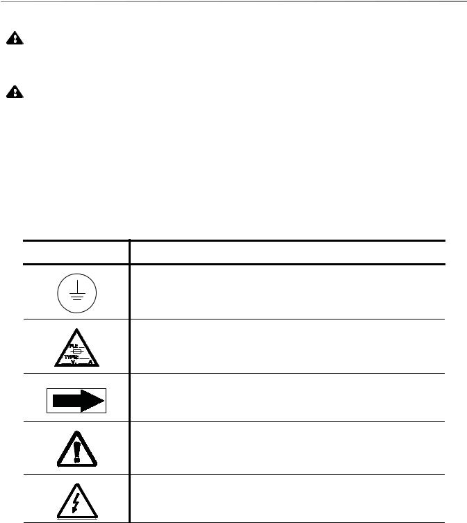
Tables 1-1 and 1-2 define certain symbols which may be on your Basil 4700 Cage and Rack Washer components:
Table 1-1. Definition of Symbols on Unit
Symbol |
Definition |
Protective Earth (Ground).
Fuse Identification.
Pump Rotation.
Attention, Consult Manual for Further Instructions.
Warning! Risk of Electrical Shock.
1-3
Safety Precautions |
Operator Manual |
920509-645 |
|
Table 1-2. Definition of Symbols on Identification Nameplate |
|
|
|
|
Symbol |
|
Definition |
|
|
|
MODEL |
|
Model Number of The Unit. |
|
|
|
S/N |
|
Serial Number of The Unit. |
|
|
|
V3~ |
|
Volt, Number of Phase (3 or 1), Alternate Current. |
|
|
|
WIRE |
|
Number of Wires In The Electrical Cable (Ground Not Included). |
|
|
|
YEAR |
|
Year of Manufacture of The Unit. |
|
|
|
k |
|
Kilovolt-Ampere. |
|
|
|
A |
|
Amperage. |
|
|
|
Hz |
|
Hertz – Frequency of The Unit. |
|
|
|
1-4
920509-645 |
Operator Manual |
Safety Precautions |

INSTALLATION VERIFICATION |
2 |
|
|
|
|
|
|
|
IMPORTANT: A listing of the Safety Precautions to be observed when operating this Cage and Rack Washer can be found in SECTION 1. Do not operate equipment until you have become familiar with this information.
2.1 Technical
Specifications
2.1.1 Voltage, Amperage and
Power Consumption
Complete uncrating and installation instructions, as well as an equipment drawing have been furnished. If any of these documents are missing or misplaced, contact STERIS giving serial, equipment and model numbers of the unit. Replacement copies will be sent to you promptly.
These specifications are intended to describe technical information given on nameplate of your washer and to state other relevant information. Check equipment drawing or identification nameplate for proper voltage and amperage.
Basil® 4700 Cage and Rack Washer operates on:
208 V, 60 Hz, 3-phase, 25 Amps;
480 V, 60 Hz, 3-phase, 15 Amps.
A protective ground is required (Class 1 Equipment).
Maximum currents and power consumptions are indicated on nameplate.
Main supply voltage not exceeding ± 10% of nominal voltage.
Installation category: Overvoltage Category II.
Always follow local electrical installation codes.
Refer to Uncrating/Installation Instructions (P920509-642) for proper connection.
2-1
Installation Verification |
Operator Manual |
920509-645 |

2.1.2 Permissible
Environmental Conditions
2.1.3Noise Level
2.1.4Seismic Anchorage
System
2.2 Installation
Checklist
This equipment is designated to give optimal results under the following conditions:
Indoor use only;
Altitude of operation up to: 6,267 ft (2,000 m);
Maximum relative humidity is 80% for temperatures up to: 88ºF (31ºC) decreasing linearly to 50% relative humidity at 104ºF (40ºC);
Pollution degree 2.
Equivalent Sound Pressure Level: 84 dB (A). Results determined according to ISO-3746: 1995 Standard: Acoustics Determination of Sound Power Levels of Noise Sources Survey Method.
A Seismic Anchorage System is available for seismic zone 3 and 4 requirements.
After your washer has been installed by qualified service technicians, complete the following checklist to assure installation is complete and correct. If you desire, contact STERIS and schedule a technician to test installation and demonstrate proper equipment operation.
To allow service of unit without shutting off building supply lines, shutoff valves (not provided by STERIS) for maintenance purposes, are installed on steam and water lines to unit. Shutoff valves must be capable of being locked in OFF position only.
Disconnect switches (not provided by STERIS) are installed in electric supply lines near washer and within 10' (3 m) of electrical control box. Disconnect switches must be capable of being locked in OFF position only.
NOTE: If washer is installed next to other equipment, shut-off valves and disconnect switch should be placed so that service can be shut off to one piece of equipment at a time.
Washer is positioned as shown on equipment drawing with required service clearance space and in relation to building supply lines.
Washer must be installed between two walls with a key-locked service door so service side is not accessible to operators.
Building steam line provides maximum dynamic steam pressure and flow rate to washer as specified on equipment drawing.
Drip leg with steam trap installed in steam supply line.
2-2
920509-645 |
Operator Manual |
Installation Verification |
Building hot water line supplies water to washer at pressure and temperature specified on equipment drawing.
Building cold water line supplies water to washer at pressure specified on equipment drawing.
Electrical supply for washer is as specified on equipment drawing.
Condensate returns are sized as specified on equipment drawing.
Vent connections are sized as specified on equipment drawing.
Recirculation pump pressure is within 25 to 60 psig.
Recirculation pump motor rotating in direction shown by arrow.
Self-cleaning screen assembly functioning properly.
Carriage drive motor rotating in direction shown by arrow.
Carriage drive system functioning properly.
Carriage drive motor amperage within rating indicated on the motor.
Optional exhaust fan rotating in direction shown by arrow.
All piping is leak-free.
Chamber sump steam coil functioning properly.
Door safety switch(es) functioning properly.
Cabinet joints are completely sealed, no leaks (for verification, run machine for 1/2 hour).
Door(s) easily opens from inside of chamber.
Safety cables immediately stop washer operation when pulled.
Each gear box plastic cap removed and replaced with air vent provided.
Floor surrounding unit has non-slip surface.
IMPORTANT: After a few weeks of operation, inspect unit for leaks. Retighten all clamps and connections.
2-3
Installation Verification |
Operator Manual |
920509-645 |

2.3 Chemical Additives
Specifications
The selection of chemical additives is open for customer preference; however, in order to achieve optimal performance, the selected chemical additives must meet as a minimum, the following specifications:
Product |
Use Dilution |
pH Range |
Other Applicable |
Description |
Range oz/gal |
at Use |
Requirements |
|
(mL/L) Dilution |
|
|
|
|
|
|
|
|
|
|
Alkaline |
1/4 - 4 |
9.0 - 12.0 |
Liquid, non-foaming and |
Chemicals |
(2 - 32) |
|
viscosity below 200 SSU |
|
|
|
(0.0004623 ft2/sec). |
|
|
|
|
Acidic |
1/4 - 4 |
3.0 - 6.0 |
Liquid, non-foaming, free |
Chemicals |
(2 - 32) |
|
rinsing and viscosity |
|
|
|
below 200SSU |
|
|
|
(0.0004623 ft2/sec). |
|
|
|
|
Descalers |
1/2 - 2 |
<2.5 |
Liquid, non-foaming, |
|
|
|
phosphoric acid-based |
|
|
|
and viscosity below |
|
|
|
200SSU |
|
|
|
(0.0004623 ft2/sec). |
|
|
|
|
NOTE: When choosing and using chemicals, take note of the following:
1)Follow chemical label recommendations for concentration of chemical to use.
2)Follow chemical manufacturer's recommendations to determine the temperature of the WASH treatment.
3)Follow chemical manufacturer's recommendations for the amount of chemical used according to water hardness.
To achieve maximum cleaning efficiency, select chemical appropriate to soil type being processed. STERIS recommends the following chemicals:
•Cage-Klenz® 100 Alkaline Cage Wash Detergent –
(Alkaline) formulated to remove urine, scale, animal fats, oils and other organic soils from cage materials.
•Cage-Klenz® 200 Acid-Based Cage Wash Detergent –
(Acidic) formulated to remove urine, scale, animal fats, oils and other organic soils from cage materials.
•Liquid Descaler Acid-Based Scale Remover – for removing scale and other hard water deposits. For use in animal care centers.
NOTE: Certain products may not be available in your area. Contact your STERIS representative for availability of these products and for ordering information.
IMPORTANT: STERIS does not promote, recommend, nor endorse the use of any other type of chemical additives in the processing of articles in the Basil 4700 Cage and Rack Washers, such as drying agents, strong alkaline detergents (pH>12), alcohol rinses, and liquid germicides including hypochloric acid (bleach).
2-4
920509-645 |
Operator Manual |
Installation Verification |

COMPONENT IDENTIFICATION |
3 |
|
|
|
|
|
|
|
IMPORTANT: A listing of the Safety Precautions to be observed when operating this Cage and Rack Washer can be found in SECTION 1. Do not operate equipment until you have become familiar with this information.
3.1 Component
Identification
Basil® 4700 Cage and Rack Washer is a heavy duty, large capacity hydrospray washer designed for thorough, efficient cleaning of cages, racks, debris pans and miscellaneous items used in the care of laboratory animals.
Washer is equipped with a user-programmable PLC control system capable of storing up to twelve treatment cycles to process a wide variety of loads. Computer control system monitors and automatically controls all cycle operations.
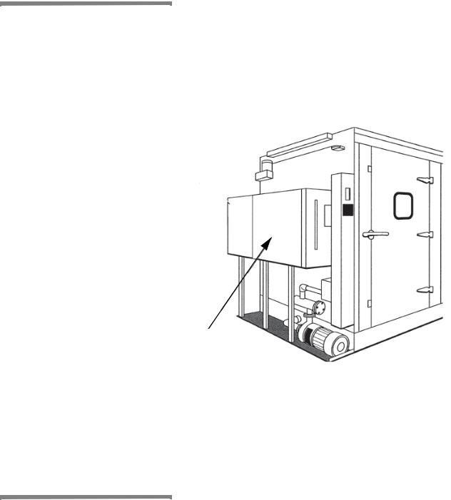
Before operating washer, it is important to become familiar with all control locations and functions (see Figure 3-1).
Chamber
Door and
Viewing
Window
Reusable-
Throwaway
Detergent
Tank
Control Console
Figure 3-1. Basil 4700 Cage and Rack Washer
Components
3-1
Component Identification |
Operator Manual |
920509-645 |

3.2 Operator Terminal See Figure 3-2.
The Basil 4700 Cage and Rack Washer is equipped with an AllenBradley CompactLogix™ Programmable Logic Controller control system1 that features twelve cycles for processing a wide variety of loads.
System monitors and controls washer operations and functions and also monitors current status of chamber, including current chamber temperature and time remaining in phase.
Control system offers four operation modes: Supervisor, Service,
Automatic and Manual. The first two modes are password protected.
Automatic and Manual modes are always available.
There is an operator terminal on load side and an operator terminal on unload side for double door units. Identical information is displayed on both load and unload operator terminals.
3.2.1 Login Passwords Supervisors and service users with appropriate password can access Supervisor mode.
Only a qualified service technician can access Service mode. A predefined password is required to access Service mode.
3.2.2 Automatic and Manual |
Automatic and Manual mode can be selected from mode selection |
Mode |
screen. No login is required to enter in Automatic or Manual modes. |
|
When accessory rack is in proper position inside wash chamber, |
|
operator closes door, manually selects desired cycle on touch |
|
screen, presses START touch pad and appropriate cycle starts. |
3.2.3 Supervisor Mode Supervisor mode allows supervisor to modify preprogrammed cycles,
parameters and options within a range of factory set values such as date and time and to enable printer functions.
 Passwords
Supervisor mode access is secured by a password. Supervisor
Operators
password is configured in Supervisor mode.
 Cycles
3.2.4 Service Mode Service mode allows a qualified service technician to access Service mode menu to configure washer and to perform preventive maintenance, testing and troubleshooting. Service mode is not accessible to operator or supervisor.
A predefined password is required to access Service mode.
1 CompactLogix™ is a trademark of Allen-Bradley, a Rockwell Automation Company.
3-2
920509-645 |
Operator Manual |
Component Identification |
3.2.5 Operator Terminal
Touch Screen
Operator terminal screen is a touch-sensitive color graphics screen. Touch screen displays current status of chamber, including current chamber temperature and phase remaining time, cycle data and operator instructions. Touch screen also indicates any faults that may occur during a cycle.
Touch pads are displayed on touch screen and vary from one menu to another. Some values may be selected in scroll down menus using arrows displayed on touch screen.
 Passwords
 Operators
 Cycles
or
!
Touch Pads:
Supervisor mode: Press Supervisor Mode on Options screen to access Supervisor Mode Login screen.
Service mode: Press Service mode on Options screen to access Service Mode Login screen.
CLOSE: Press X (CLOSE) on touch screen to exit a screen and return to previous screen.
Left or Right arrow: For forward and back navigation. Press Left or Right arrow on touch screen to scroll across a screen to view all menus and/or possible selections available.
BACKSPACE: Used on Keyboard and Numeric Keyboard screens. Press BACKSPACE on touch screen to move one position backwards and delete the preceding space or character.
ENTER: Press ENTER on touch screen to confirm a selection and/or an entry.
STOP: Press STOP on touch screen to interrupt or abort cycle.
ALARM: Symbol displayed on Alarm screen, along with FAULT messages.
3-3
Component Identification |
Operator Manual |
920509-645 |
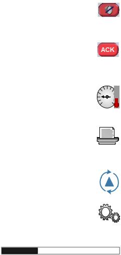
SILENCE BUZZER: Press SILENCE BUZZER on touch screen to stop alarm buzzer.
ACK: Press ACK on touch screen to stop alarm buzzer and acknowledge displayed FAULT messages.
DETAILS: Press DETAILS on touch screen to view current cycle written data of parameters.
PRINT: Press PRINT on touch screen to print specific information from the Cycle, Service and Supervisor modes.
CYCLES: Press CYCLES on touch screen to access Cycles menu.
GEARS: Press GEARS on touch screen to access Machine Setup menu.
Progress Bar: Progress Bar is displayed on Chamber screen while cycle(s) is (are) in progress to show cycle(s) progress.
3.2.6 Audible Signal An audible signal warns operator that an action must be taken.
3-4
920509-645 |
Operator Manual |
Component Identification |
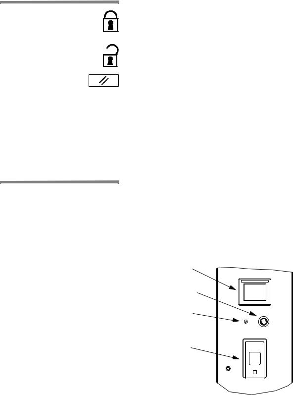
3.3 LOCK/UNLOCK/
INIT Key Switch
3.4 Printer
The LOCK/UNLOCK/INIT key switch is located on control panel door and includes three positions:
•LOCK – Use key to turn selector switch to the left to LOCK position to lock washer for minor maintenance purposes (i.e. cleaning sump). The operator cannot start a new cycle or enter into the Service mode.
•UNLOCK – Use key to turn selector switch to UNLOCK position to unlock washer and enable washer to function normally, i.e. start cycles or enter into the Service mode.
•INITIALIZATION – Use key to turn selector to the right to reset washer normal operation after emergency stop cables or EMERGENCY STOP pushbutton were activated, after a power up or the return of current after a power failure.
NOTE: Selector returns automatically from initialization to UNLOCK position when key is released.
LOCK/UNLOCK/INIT key switch can be turned only using a key. For added safety, key must be accessible only to trained operators.
See Figure 3-2.
A printer is available for use with the Basil 4700 Cage and Rack Washer. Refer to printer User’s Manual [PM190/192-TUD] for detailed information about printer.
Printer allows operator to print cycle data and washer malfunction data. Specific information is printed from Cycle mode (cycle parameters, alarms), Service mode (washer configuration values) and Supervisor mode (supervisor’s list, supervisor setup).
Printer uses 2-1/4" (57 mm) wide, 2" (50 mm) dia. single ply paper (P117913-393) and Ink ribbon (P117026-048)
Display
EMERGENCY STOP
Pushbutton
LOCK/UNLOCK/INIT
Key Switch
Printer
Figure 3-2. Operator Terminal and Printer
3-5
Component Identification |
Operator Manual |
920509-645 |

3.5 Typical Printouts
|
|
|
_ _ _ _ _ _ _ _ _ _ _ _ _ _ _ _ _ _ _ _ _ _ _ _ _ _ _ _ _ _ _ |
||
CYCLE - CYCLE 4 |
|
|
_ _ _ _ _ _ _ _ _ _ _ _ _ _ _ _ _ _ _ _ _ _ _ _ _ _ _ _ _ _ _ |
||
CYCLE START |
2007-03-30 09:22:22 |
|
CYCLE COUNT |
63 |
|
SERIAL NUMBER: 36XXXXXXXX |
|
|
ALK. WASH |
|
|
- START |
09:28:59 |
47.5ºC |
- END |
09:29:04 |
43.5ºC |
-DRAINING SUMP 09:29:15
-TEMPERATURE 31.0ºC
ACID WASH |
|
|
- START |
09:30:45 |
81.9ºC |
- END |
09:34:48 |
77.8ºC |
- ACID SOAK |
09:34:53 |
|
- BYPASSED |
|
|
- DAINING SUMP |
09:35:86 |
|
- TEMPERATURE: |
57.7ºC |
|
FINAL RINSE |
|
|
- START |
09:35:26 |
42.9ºC |
- END |
09:35:37 |
32.5ºC |
Figure 3-4. Sample Printout
3-6
Figures 3-3 and 3-4 are examples of typical cycle printouts.
•POWER UP
When Power Switch is set to POWER, generated printout lists time and date, control was turned on and unit's serial number.
•CYCLE START
When cycle is started, generated printout lists name of cycle started, time and date cycle was started, cycle number and unit number.
•IN-CYCLE PERFORMANCE
During a cycle, generated printout lists start and end time of each phase, along with actual temperature of solution/water in chamber sump.
•END-OF-CYCLE PERFORMANCE SUMMARY
At end of a cycle, generated printout lists time cycle was completed, maximum wash and rinse temperatures reached during cycle and total cycle processing time.
•ALARM CONDITION
When an alarm condition occurs, generated printout lists type of alarm and time it occurred (see Figure 3-3). Once operator presses ACK touch pad, generated printout lists time when alarm was acknowledged.
* ALARM
2007-03-30 09:43:59
COOLDOWN TANK TOO LONG TO DRAIN
Figure 3-3. Sample Alarm
Printout
920509-645 |
Operator Manual |
Component Identification |
3.6 Oscillating Jet
System
Oscillating jet system consists of two spray headers, one on each side of wash chamber, suspended from an oscillating carriage (see FIGURE 3-5). Each spray header is equipped with machined jets angled to reach all surfaces of load.
Oscillating jet system travels back and forth along length of chamber during recirculating/spraying phase function. Jet system is equipped with a safety clutch that stops movement of oscillating carriage if an obstruction is detected.
 Oscillating
Carriage
Spray |
|
|
|
Headers |
|
Spray |
|
|
|
|
Jets |
Figure 3-5. Oscillating Jet System
3-7
Component Identification |
Operator Manual |
920509-645 |
3.7 Safety System
WARNING – PERSONAL INJURY AND/OR EQUIPMENT DAMAGE HAZARD: To open doors from inside wash chamber, pull EMERGENCY STOP cables. Washer operation will automatically stop. Then, push firmly on door panel using shoulder and upper arm, applying upper body force.
Chamber doors are equipped with a safety switch to stop washer operation if door is opened during a cycle and to prevent start of washer operation if door is not securely closed.
Chamber doors are also equipped with a spring-loaded, explosion relief type safety latch. Door can be easily opened when pushed from inside of wash chamber.
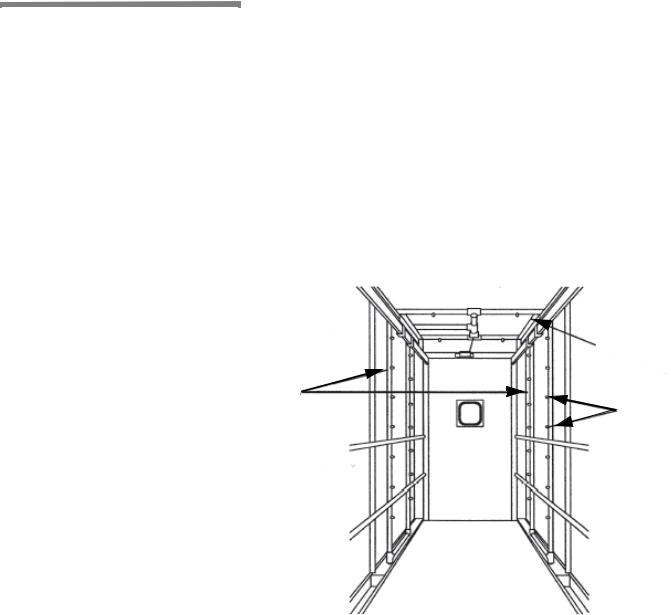
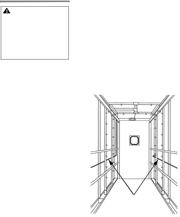
Two stainless-steel, red-coated safety cables are installed inside wash chamber, one along each side (see FIGURE 3-6). If cable is pulled, washer operation is immediately stopped.
Oscillating jet system is equipped with a mechanical clutch to disengage carriage drive if an obstruction is encountered, preventing damage to spray headers and load items.
Load-side and unload-side control panels are equipped with EMERGENCY STOP pushbuttons. If pushbutton is pressed, washer operation is immediately stopped.
Safety Cables
Figure 3-6. Safety Cables
3-8
920509-645 |
Operator Manual |
Component Identification |
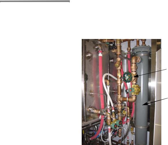
3.8 Heat Exchanger Washer is equipped with a steam heat exchanger and valving system to preheat incoming fill water, reducing normal water/solution heat-up time (see Figure 3-7).
System is fully automatic and works during filling function of Prewash, Wash treatment (if the corresponding tank is not present) and Rinse phases. Heat exchanger steam valve is energized only if temperature is below 165°F (73.9°C).
 Heat Exchanger
Steam Throttling
Valve
 Heat Exchanger
Figure 3-7. Heat Exchanger
3-9
Component Identification |
Operator Manual |
920509-645 |

3.9 Automatic
Detergent Injection
System
Automatic Detergent Injection System includes a peristaltic pump mounted to washer exterior. System also includes a conductivity probe located in chamber sump.
If using alkaline detergent with injection system, alkaline detergent is automatically injected into chamber sump during Wash phase of a cycle.
•Once sump is full, control checks detergent concentration of solution in sump. Alkaline detergent is then injected into sump until solution reaches set concentration level. Alkaline detergent solution is monitored and maintained at set concentration level while recirculating and spraying over load.
If using acid detergent with injection system, acid detergent is automatically injected into chamber sump during Acid Wash phase of a cycle.
•Once sump is full, control checks detergent concentration of solution in sump. Acid detergent is then injected into sump until solution reaches set concentration level. Acid detergent solution is monitored and maintained at set concentration level while recirculating and spraying over load.
3.10Reusable- Washers equipped with Reusable-Throwaway Detergent System can
Throwaway Detergent
System
be programmed to either save or drain detergent solution on completion of phase.
System includes a separate detergent tank and piping constructed of stainless steel. Detergent tank is equipped with a steam coil to maintain detergent solution at programmed temperature. ReusableThrowaway Detergent System can be installed for alkaline and/or acid detergent
3-10
920509-645 |
Operator Manual |
Component Identification |
3.11 Non-Recirculated
Final Rinse
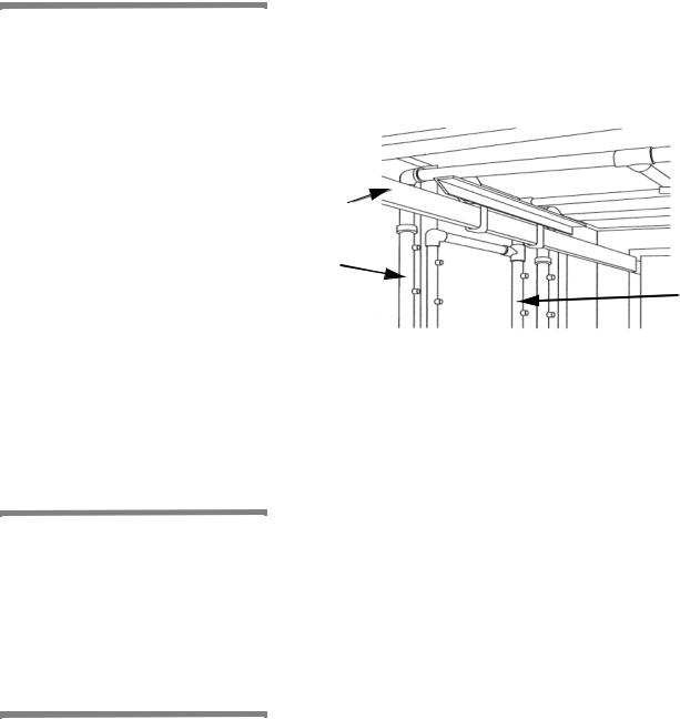
Washers equipped with Non-Recirculated Final Rinse System can be programmed to spray load with fresh, non-recirculated water during standard Final Rinse phase. System includes a separate spray header mounted directly to each side of oscillating carriage, inside of main spray headers (see Figure 3-8).
Carriage
Rail
Main Spray |
Separate |
Spray |
|
Header |
Header For |
|
Fresh |
|
Water |
3.12 Feeder Bottle
Washing System
3.13 Automatic Water
Flush System for Two
Racks
Figure 3-8. Non-Recirculated Final Rinse Spray Header
Feeder Bottle Washing System provides capability of processing a loaded bottle cart during normal cycle operation. System includes a quick disconnect coupler.
NOTE: Bottle washing cart is available as a separate accessory.
Cycle must be programmed to process bottle cart during cycle operation.
Automatic Water Flush System for two racks permits cleaning of facility’s automatic watering system during normal cycle operation. System includes a set of two hoses, each equipped with a quick disconnect fitting, mounted on service side carriage rail.
Hoses are manually connected to customer cage watering racks moved into wash chamber. During Final Rinse filling, fresh hot water is sent through heat exchanger (for recirculated final rinse, temperature setpoint should be over 165ºF [73.9ºC] to activate heat exchanger) and sprayed over cage watering racks for programmed filling time interval.
3-11
Component Identification |
Operator Manual |
920509-645 |
3.14 Drain Discharge
Cooldown with Side
Tank and Temperature
Guarantee
A separate tank is typically mounted along service side of washer to temporarily retain and cool all drain discharges (see Figure 3-9).
NOTE: Location of drain discharge side tank may change depending on other options ordered with washer.
During draining function of each phase, if sump water temperature is over 140ºF [60ºC], solution/water in sump is automatically pumped to side tank where cold tap water is added. Cold water remains on until water temperature in side tank reaches programmed set point. Once cooled to set temperature, side tank gravity drains to building drain system.
3.15 Drain Discharge Cooldown System with Cold Water Injection Only
Drain Discharge
Side Tank
Figure 3-9. Drain Discharge Side Tank (Typical)
Washer drain system is piped to automatically cool all drain discharges using building cold water supply.
During draining function of each phase, cold tap water is injected into washer drain line as washer drain discharges are sent directly to building drain system. Cold water remains on until sump drain valve closes.
3-12
920509-645 |
Operator Manual |
Component Identification |
Loading...