


UNCRATING/INSTALLATION INSTRUCTIONS
®
Basil
4600 Cage and Rack Washer
Basil® 4602 Cage and Rack Washer
(2004-02-13) P910000-015

A WORD FROM STERIS CORPORATION
Advisory
Follow each step of these
presented. To avoid damage to the equipment inside, open the carton
carefully
slight), show it to your supervisor.
To properly install this unit, you will need the Equipment Drawings provided,
showing all utility service and space requirements. If drawings cannot be
located, replacement copies may be obtained by writing, faxing, or telephoning STERIS, giving the serial number and model of your unit.
Once installed, unit operation should be tested by a STERIS-trained service
technician prior to your equipment usage.
If STERIS supervision is desired for installing and starting up this equipment,
contact STERIS for pricing and availability of this service in you region.
IMPORTANT: This unit is specifically designed to only process goods as
outlined in
A listing of the
and testing this equipment can be found in Section 1 of this manual. Do not
begin uncrating/installing the equipment until you have become familiar with
this information.
Any alteration of this equipment not authorized or performed by STERIS which
could affect equipment operation will void the warranty, could adversely affect
cleaning efficacy, could violate national, state, and local regulations, and could
jeopardize your insurance coverage.
. If you find any indication of damage to the equipment (no matter how
Operator Manual
Safety Precautions
Uncrating/Installation Instructions
(P122997-341).
to be observed when uncrating, installing,
in the order
To assure operators are adequately trained in the safe use of the equipment,
STERIS recommends that:
• all personnel who operate or maintain the equipment are trained in its
operation and in its safe use;
• personnel working with toxic chemicals and vapors (if applicable) have
comprehensive instructions in the unit, process, relevant health hazards,
and methods to detect the escape of toxic materials;
• there is regular training of all personnel concerned with the operation and
maintenance of the equipment; attendance records are maintained; and the
evidence of understanding is demonstrated.
©2004, STERIS Corporation. All rights reserved. Printed in Canada
Table of Contents Uncrating/Installation Instructions 910000-015
i

Indications for Use
Service Information
The Basil® 4600 Cage and Rack Washer and Basil® 4602 Cage and Rack
Washer are heavy duty, large capacity hydrospray washers designed for
thorough, efficient cleaning of cages, racks, debris pans and miscellaneous
items used in the care of laboratory animals.
These units are specifically designed to only process goods as outlined in the
Operator Manual. If there is any doubt about a specific material or product,
contact the manufacturer of the product for the recommended washing
technique.
A thorough preventive maintenance program is essential to safe and proper
unit operation. You are encouraged to contact STERIS concerning our comprehensive Annual Maintenance Agreements. Under the terms of these agreements, preventive maintenance, adjustments, and replacement of worn parts
are done on a scheduled basis to help assure equipment performance at peak
capability and to help avoid untimely or costly interruptions. STERIS maintains
a global staff of well equipped, factory-trained technicians to provide this
service, as well as expert repair services. Please contact STERIS for details.
For contact information, see inside back cover.
Certification
The Basil 4600 Cage and Rack Washer and Basil 4602 Cage and Rack
Washer meet the applicable requirements of the following standards:
• Underwriters Laboratories (UL) Standard 1262, as certified by ITS Testing
Laboratories, Inc.
ii
910000-015 Uncrating/Installation Instructions Table of Contents

TABLE OF CONTENTS
Section Title Page
A WORD FROM STERIS CORPORATION ............................................ i
Advisory ................................................................................................................................. i
Indications for Use ................................................................................................................. ii
Service Information ................................................................................................................ii
Certification ............................................................................................................................ii
1 LISTING OF SAFETY PRECAUTIONS ............................................. 1-1
Definition of Symbols ......................................................................................................... 1-2
2 INSTALLATION REQUIREMENTS ................................................... 2-1
3 ASSEMBLY INSTRUCTIONS ........................................................... 3-1
3.1 General Guidelines ...................................................................................................... 3-1
3.2 Base ........................................................................................................................... 3-1
3.3 Cabinet ...................................................................................................................... 3-4
3.4 Chamber (Inner Cabinet) ............................................................................................ 3-11
3.5 Service Side of Cabinet.............................................................................................. 3-15
3.6 Top of Cabinet ............................................................................................................3-19
3.7 Final Assembly/Clean-up ........................................................................................... 3-20
4 INSTALLATION CHECKLIST .......................................................... 4-1
5 OPERATIONAL CHECKLIST ........................................................... 5-1
Table of Contents Uncrating/Installation Instructions 910000-015
iii

LISTING OF SAFETY PRECAUTIONS
1
The following listing of
potential for danger to personnel, and CAUTIONS indicate the potential for damage to equipment. These
Precautions
are repeated, where applicable, throughout the manual.
Safety Precautions
must be observed when installing this equipment. WARNINGS indicate the
WARNING – PERSONAL INJURY HAZARD:
When handling cabinet panels, use extreme care and wear protective gloves. Panels are heavy and may have
sharp edges.
When positioning cabinet panels two people are required to lift and support each panel because of weight and
size. One person must support panel while the other person installs the nuts and bolts.
Before placing any weight on the roof panel, secure panel on top of cabinet by installing bolts and nuts, finger tight,
in all four corners of roof panel.
When installing doors, more than one person is required to lift doors because of weight and size.
When installing control column(s), more than one person is required to lift control column in place because of weight
and size.
When installing detergent tank, more than one person is required to lift tank because of weight and size.
When moving sump coil, more than one person is required to lift coil because of weight and size.
Safety
CAUTION – POSSIBLE EQUIPMENT DAMAGE:
When checking rotation of drive motor, use extreme caution. If rotation is incorrect, carriage will run directly into
the door header.
Listing of Safety Precautions Uncrating/Installation Instructions P910000-015
1-1

Definition of
Symbols
Symbol Definition
Protective Earth (Ground)
Warning! Risk of Electrical Shock
1-2
P910000-015 Uncrating/Installation Instructions Listing of Safety Precautions

INSTALLATION REQUIREMENTS
NOTE: Please review these instructions carefully prior to installing equipment.
Follow instructions in the sequence given.
1. Review installation site and room layout drawings provided with Installation
Kit. It may be necessary to vary the actual installation from the drawings due
to space limitations or existing obstructions.
2. If necessary, unload, uncrate and move equipment to installation site. Refer
to
Uncrating / Utility Connection Instructions
unit.
3. If handling disposal of debris, ensure customer signs off on the disposition
of trash left on the job site.
4. Check the Occupational Health and Safety Act as well as local electrical and
plumbing codes for any special requirements that may pertain to the
installation of this equipment.
5. Recommend to customer that shutoff valves be installed at readily
accessible locations in steam and water supply lines near the equipment.
6. Recommend to customer that disconnect switch (with OFF position lockout
only) be installed in electric supply line within 10 feet of the equipment.
2
(P910000-016) shipped with
NOTE: If washer is installed next to other equipment, shutoff valves and
disconnect switch must be placed so that service can be shut off to any one piece
of equipment at a time.
2-1
Installation Requirements Uncrating/Installation Instructions P910000-015
INSTALLATION INSTRUCTIONS
1. All mounting hardware necessary for complete installation is shipped with
3.1 General Guidelines
3.2 Base
the unit. Not every piece of mounting hardware will be utilized; ample
amounts are provided.
2. If necessary, use 6'' X 6'' X 1/8'' thick stainless-steel shims to level
equipment. Do not exceed 3/4-inch shim height. If equipment requires more
than 3/4" shimming material, use square tubing to level equipment.
3. Use silicone (RTV) provided in Installation Kit to seal all panel joints to
assure water tightness. When caulking, silicone bead should be a minimum
of 1/4 inch wide and completely circle all bolt holes. When in doubt, use
silicone liberally. It is easier to prevent a leak during assembly than to fix
a leak once equipment is in use.
4. All bolts going to atmosphere (from inside of chamber to outside of cabinet)
require sealing washers.
5. All bolts require lockwashers, except the welded nuts along the non-service
side of the washer.
1. Lift door grating and remove sump coil from base. Replace floor grating in
base.
3
2. Position base according to room layout drawings, either in a pit or on the
floor. It pit mounted, make sure face of surface is parallel to pit wall (within
two to thee inches from the non-service side wall) or positioned as specified
in the room layout drawings.
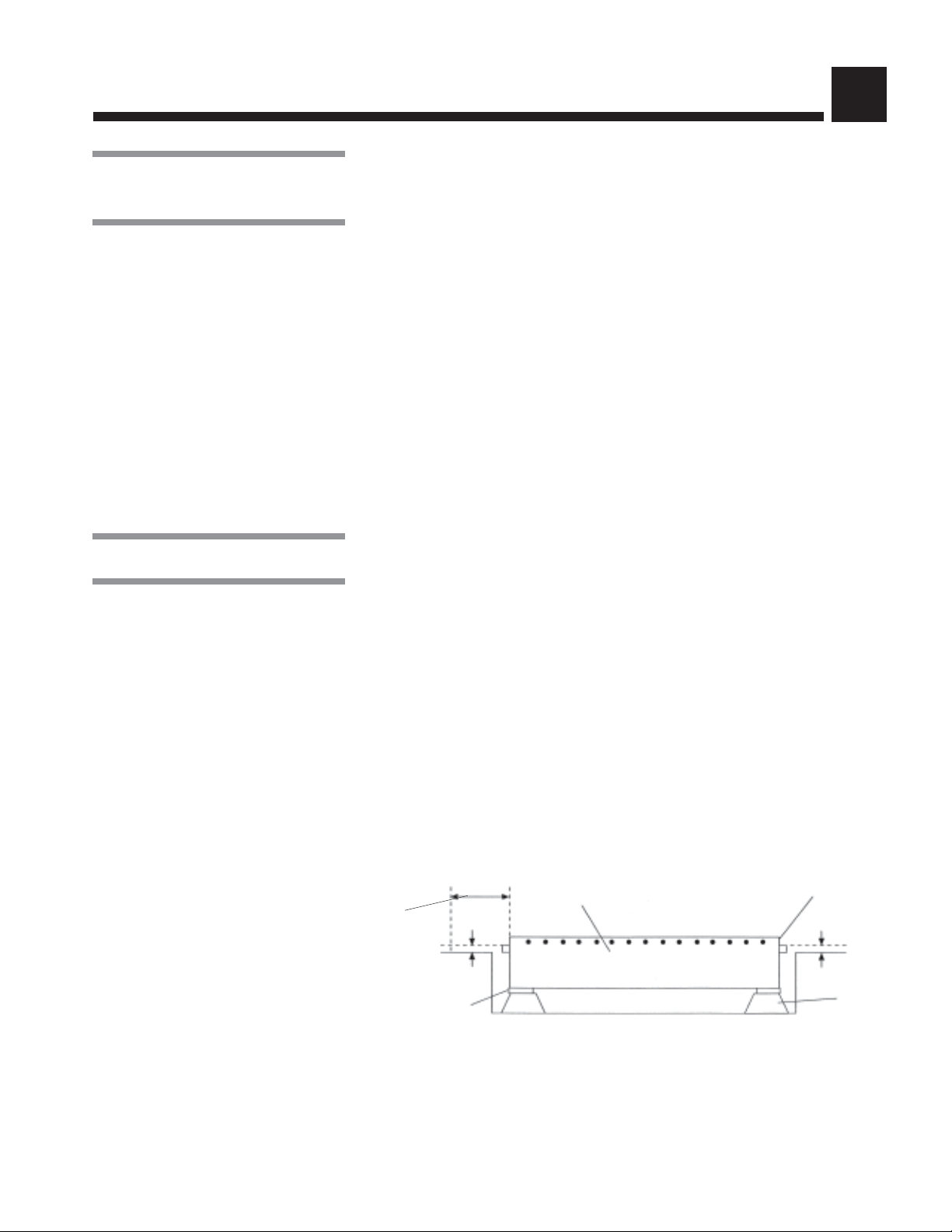
3. Check base height (see Figure 3-1). Ensure the door threshold is at least 1/4"
higher than the highest spot on the floor, along the netire door swing (four
feet from base). If necessary, position shims under corners of base.
Door Threshold
1/4"
Four Feet
Door Swing
1/4"
Add shims here, if
necessary, to achieve
proper height and level
Base
Pit Pad
Figure 3-1. Check Base Height
3-1
Installation Instructions Uncrating/Installation Instructions 920000-015

If pit mounted, use a four-foot level to check the door swing (see
Figure 3-2). Hold one end of level on door threshold and place two 1/8-inch
shims under the opposite end. Check door swing at 90°, 45°, and 15°.
NOTE: When shimming, ensure shim is placed under corner of base with part of
the shim exposed.
Door Threshold
Foor-Foot Level
Figure 3-2. Check Door Swing
4. Check level of base along face and length. If necessary, position shims
under corners of base. If shims are used to level base, base height must
be re-checked once the base is level.
5. In some instances, the base may be shipped in two or three pieces. If base
is split, assemble base pieces as follow:
a. Position base pieces, next to one another, close to the final location
indicated on the room layout drawings.
b. Connect the base pieces by installing the floor grating supports down the
center of the base and on either side of the door threshold (see Figure 3-3).
Floor Grating Supports
Door Threshold
Base
Figure 3-3. Install Floor
c. Align the base pieces by stretching a string across the four alignment
marks located on the side of each piece (see Figure 3-4). If necessary,
position shims under corners of base piece(s).
Alignment
Mark
Alignment
Mark
Alignment
Mark
Base Pieces
Figure 3-4. Align Base Pieces
3-2
910000-015 Uncrating/Installation Instructions Installation Instructions

d. Check base height and level of base as explained in Steps 3 and 4.
e. Once base is level, spot weld a series of one-inch welds along the base
seams to maintain the established position.
NOTE: The heat generated by most welding operations will damage epoxy/vinyl
flooring. Take appropriate precautions to protect floor from heat and welding arc.
f. Completely weld all base pieces together from the inside.
g. Check for pin holes and incomplete welds. All welds must be water tight.
h. Clean up welds using a wire brush.
6. If shims were used, weld shims in place to form a solid foundation (see
Figure 3-5).
Base
Weld
Shims
Pit Pad
Figure 3-5. Weld Shims
7. Attach pump plate to service side of washer (see Figure 3-6). Ensure
brackets are facing up and plate does not cover drain hole.
Pump
Plate
Brackets
(Facing Up)
Service Side
of Washer
Drain Hole
Figure 3-6. Install Pump Plate
8. Check level of pump plate along the plate width and length. If necessary,
position shims under the brackets attached to pump plate. Silicone shims
in place, using a heavy bead of silicone between the shims, between the
pump plate and shims and between the shims and floor.
If pit mounted, ensure shims are flush with the pit wall.
9. Re-tap threads on all welded nuts (along the non-service side of the washer)
with 5/16''-18 threads/inch tap.
3-3
Installation Instructions Uncrating/Installation Instructions 920000-015

3.3 Cabinet
WARNING–PERSONAL
INJURY HAZARD:
• When handling cabinet panels, use extreme care and
wear protective gloves. Panels are heavy and may have
sharp edges.
• When positioning cabinet
panels, two people are required to lift and support
each panel because of
weight and size. One person must support the panel
while the other installs the
nut and bolts.
NOTE: Cabinet must be completely assembled and tightened within the same
day, before silicone hardens.
1. Remove paper from all cabinet panels.
2. Select any corner panel to begin cabinet assembly.
3. Count the number of bolts holes along side of corner panel (e.g. six bolt
holes). Do not count bolt holes along face (load/unload side) of corner panel.
NOTE: When caulking, fully open caulk nozzle to allow for a heavy silicone bead.
4. On inside of base, silicone around and between the number of bolt holes
counted plus one (e.g. seven bolt holes; see Figure 3-7). Do not silicone
along face of unit
..
. Make sure to silicone in a consistent line.
..
NOTE: Only silicone around and between the base bolt holes needed to install
one panel at a time.
DO NOT Silicone
Face of Cabinet
Silicone
Bolt Holes
Figure 3-7. Silicone Around and Between Bolt Holes
5. Position bottom of corner panel on base lip. Using your foot, hold bottom
of panel on the lip and raise panel up into place. Insert alignment pins, one
on either end, to align panel and base bolt holes (see Figure 3-8).
NOTE: All bolts going to atmosphere (from inside of chamber to outside of
cabinet) require sealing washers. All bolts require lockwashers, except the
welded nut along the non-service side of the washer.
Alignment
Pin
Corner
Panel
Alignment
Pin
Base Lip
Figure 3-8. Insert Alignment Pins
3-4
910000-015 Uncrating/Installation Instructions Installation Instructions

6. Attach panel to base. Ensure bolts along face of base are installed with the
bolt heads located on outside of base, and bolts along side of base are
installed with the bolt heads located on inside of base (see Figure 3-9).
NOTE: During panel assembly, all bolts are installed snug (tight enough to flatten
the silicone). Once cabinet is completely assembled, bolts will be securely
tightened.
Bolt and Sealing
Washer
Nut and
Lockwasher
Nut and
Lockwasher
Side of Base
Face of Base
Bolt and Sealing
Washer
Figure 3-9. Bolt Positions for Corner Panel
7. Locate next panel to be installed. Each panel is numbered and installed in
sequential order, starting with the number assigned to the first corner panel
installed.
8. Count the number of bolt holes along bottom of panel.
9. Starting from top of installed panel, silicone around and between bolt holes
along the vertical panel joint and along inside of base (see Figure 3-10).
When caulking base, ensure to silicone around the number of bolt holes
counted plus one.
NOTE: Critical Leak areas are at the top and bottom of vertical panel joints, and
along base seams if base was split. Use silicone liberally in these areas.
Bolt Holes
Silicone
Figure 3-10. Silicone Vertical Panel Joint and Base
3-5
Installation Instructions Uncrating/Installation Instructions 920000-015

10. Position bottom of panel on base lip, with the panel tilted toward inside of
base and two inches away from installed panel (see Figure 3-11). Using your
foot, hold bottom of panel on the lip and slide panel over to within 1/2 inch
of the installed panel. Raise panel up into place; avoid smearing the
silicone. Insert alignment pins through farthest holes, one along horizontal
joint and one along vertical joint as high as possible.
Panel Tilted
Toward Base
Silicone
Base
Lip
Figure 3-11. Install Side Panel
11. Install sealing strip over vertical joint (see Figure 3-12). Ensure numbers on
sealing strip match the connecting panels.
NOTE: When installing sealing strip, ensure panel is supported while alignment
pin is temporarily pulled from the vertical joint.
Sealing Strip
Vertical Joint
Figure 3-12. Install Side Panel
3-6
910000-015 Uncrating/Installation Instructions Installation Instructions

12. Attach panel to base and adjacent panel. Make sure bolts along vertical
joint are installed with the bolt heads facing toward center of cabinet (see
Figure 3-13).
Side Panels
Nut and
Lockwasher
Bolt &
Sealing
Washer
Roof Panel
Nut and
Lockwasher
Bolts
Nut and
Lockwasher
Figure 3-13. Bolt Positions for Side and Roof Panels
13. Install remaining side and corner panels following Steps 3 through 12.
14. Locate door header(s). If pass-through unit, door headers are labelled
according to where the header should be mounted (i.e., load or unload end
of cabinet).
15. Silicone both ends of door header and the mounting area on each corner
panel.
16. Position door header between corner panels using alignment pins to align
header and panel bolt holes (see Figure 3-14). Attach door header to corner.
Door
Header
Control Panel
Silicone
Alignment Pin
Figure 3-14. Position Door Header
17. Verify door header is flush with front (face) of cabinet. Securely tighten bolts
attaching door header to corner panels.
18. Along top of cabinet, fill each joint between the connected panels with
silicone. Run a continuous line of roof gasket along top of each panel. Center
gasket over bolt holes. Silicone between any gasket seams.
3-7
Installation Instructions Uncrating/Installation Instructions 920000-015

19. Working from the top of the cabinet, punch bolt holes through the roof gasket
using alignment pin.
20. Install a continuous line of roof gasket along both sides of the center roof
panel (see Figure 3-15). Start end of gasket along edge of roof panel, below
first bolt hole. Bend gasket up and run gasket over center of the bolt holes.
Before last bolt hole, bend gasket down and finish by running gasket along
edge of roof panel, below last bolt hole. Using an alignment pin, punch bolt
holes through the roof gasket.
Gasket
Bolt Hole
Center Roof
Panel
Side Cabinet
Panel
Figure 3-15. Install Gasket on Center Roof Panel
WARNING–PERSONAL
INJURY HAZARD: Before
placing any weight on the
roof panel, secure panel on
top of cabinet by installing
bolts and nuts, finger tight,
in all four corners of roof
panel.
21. Attach roof panels starting from one end of the cabinet. Panels are labelled
indicating which end is attached to the service side of the cabinet. Use
alignment pins to align bolt holes and install bolts finger tight. Ensure bolts
are installed with the bolt heads located on inside of cabinet (see
Figure 3-13).
NOTE: When lifting roof panels to top of cabinet, do not slide panels over the roof
gasket.
22. Once cabinet is assembled, place a 1/4-inch shim on either side of door
opening.
23. Locate chamber door(s) and verify door latches are open. When open, tooth
is visible; when closed, solid block is visible (see Figure 3-16).
Door Latch
1/4'' Shim
Tooth Visble; Door
Latch Is Open
Figure 3-16. Verify Door Latch is Open
3-8
910000-015 Uncrating/Installation Instructions Installation Instructions

WARNING–PERSONAL
INJURY HAZARD: When installing doors, more than
one person is required to
lift doors because of it
weight and size.
24. Position bottom of door on shims and raise door up into place (see
Figure 3-16). Push door closed.
25. For each door hinge, insert alignment pin through hinge (from the bottom)
to align door and cabinet hinges (see Figure 3-17). Place four-inch door pin
in top of hinge.
26. Using an alignment pin, raise hinges enough to insert first bushing (see
Figure 3-17). Hammer door pin partially down through first bushing. Insert
second bushing and hammer door pin down completely.
Door Pin
Door Hinge
Alignment Pin
Bushing
Figure 3-17. Align Door and Cabinet Hinges
NOTE: It may be necessary to hammer bushing in place between door and
cabinet hinges.
27. Once all door pins and bushings are installed, open door and check door
swing.
28. Verify cabinet is in final position. Verify face of cabinet (load end) is aligned
with face of customer wall. If cabinet position must be adjusted, check level
of cabinet along face and lenght of roof after moving cabinet.
29. To prevent chamber door(s) from sagging while tightening the cabinet
bolts, place a 1/8-inch shim between door header and the non-hinged side
of the door (see Figure 3-18). Using a pry bar between the door threshold
and bottom of door, raise non-hinged side of door and tightly pack the
opening with shims.
1/8'' Shim
PryBar
Figure 3-18. Raise Non-Hinged Side of Chamber Door
3-9
Installation Instructions Uncrating/Installation Instructions 920000-015

30. Securely tighten cabinet bolts in the order listed below (see Figure 3-19):
a. Bolts along vertical joints (sealing strips) connecting cabinet side and
corner panels together.
b. Bolts along cabinet sides and face connecting the base to the cabinet side
and corner panels.
c. Bolts along inner roof panel joints connecting the roof panels together.
d. Bolts along outside of roof panels connecting the roof panels to the cabinet
side and corner panels.
NOTE: If using an impact gun to tighten bolts, do not use the impact gun on
welded nuts located along non-service side of cabinet.
Inner Roof
Panel Joints
Outside Roof
Panel Joints
Vertical Joints
Cabinet Sides and Face
Figure 3-19. Tighten Cabinet Bolts
31. Weld base to face of corner panels using three 1-inch welds on both sides
of door opening (see Figure 3-20).
1-Inch
Welds
Base
1-Inch
Welds
Figure 3-20. Weld Base
32. Attach high voltage electrical box to service side of cabinet. Open electrical
box door and verify that adequate space is available for service access.
3-10
910000-015 Uncrating/Installation Instructions Installation Instructions

WARNING–PERSONAL
INJURY HAZARD: When installing control column(s),
more than one person is
required to lift control column in place because of
weight and size.
33. Attach control column(s) to cabinet. Control column, containing printer, is
mounted on load end of cabinet. If pass-through unit, additional control
column is mounted on unload end of cabinet.
If unit is pit mounted, use a 2 X 4 to balance control column over pit while
attaching column to cabinet (see Figure 3-21).
NOTE: When attaching control column to cabinet, lower door on control column
must be opened to access bolt holes.
Control Column
Cabinet
2" X 4"
Figure 3-21. Attach Control Column
3-11
Installation Instructions Uncrating/Installation Instructions 920000-015

3.4 Chamber (Inner Cabinet)
1. Loosely attach U-bolts to cabinet, two on each side of door opening(s) at
waist height (see Figure 3-22).
U-Bolt
Safety
Cable
Guide
Bracket
U-Bolt
Safety Cable
Socket
Figure 3-22. Attach U-Bolts
2. Install drive cable roller brackets with roller facing up. Attach two brackets
to service side of cabinet exterior, one at each end and two brackets to
cabinet interior, one at either end of chamber centered above door opening
(see Figure 3-23). Ensure outer brackets are installed with open side facing
center of cabinet, and inner brackets are installed with the open side facing
service side of cabinet.
Drive Cable
Roller Brackets
Service Side
of Cabinet
Figure 3-23. Install Drive Cable Roller Brackets
3. Install carraige rails to inside of the brackets located one inch from top of
door opening(s), on both sides of the chamber. Completely attach both
ends of the first carriage rail, and attach only one end of the second rail.
Allow second rail to hang from bracket.
3-12
910000-015 Uncrating/Installation Instructions Installation Instructions

4. Position one side of the carriage on top of the fixed carriage rail (see
Figure 3-24). Ensure eye bolts in center of carriage are facing down and the
carriage hose connector is located on the same side as the cabinet hose
connector.
Carriage
Fixed Carriage
Rail
Figure 3-24. Position Carriage on
Top of Fixed Carriage Rail
5. While supporting the carriage, raise second carriage rail up into position
and attach loose end of rail to inside of bracket (see Figure 3-25). Tighten
bolts at both ends of second rail.
Bracket
Carriage
Carriage Rail
Figure 3-25. Attach Second Carriage Rail
6. Verify carriage rides smoothly along the rails.
7. Rotate the spray header connectors, two on either side of carriage, down
to 90°. Connect the U-shaped spray headers to the connectors on the
carriage.
NOTE: U-shaped spray headers and header connectors are labelled. Connect
appropriate spray header to corresponding connectors.
3-13
Installation Instructions Uncrating/Installation Instructions 920000-015

8. Attach safety hold-down brackets (J-brackets) to the carriage, two on eachside. Position bracket between the carriage and carriage rail, just inside of
the carriage wheel toward the center of the chamber (see Figure 3-26).
Mount brackets directly onto the carriage at a 90° angle to the carriage rail.
Carriage
Wheel
Carriage
Rail
Hold-Down
Carriage
Safety
Brackets
Figure 3-26. Attach Safety Hold-Down Brackets
9. Install hose by connecting one end to the carriage hose connector and the
other end to the cabinet hose conncector, located along bottom center of
chamber wall. If necessary, rotate hose (not nipple) to center it in space
between chamber wall and U-shaped spray header. Do not allow hose to rub
against chamber wall, spray headers, or safety cable.
10. Install two guide rails along each side of chamber. Insert guide rail (one-inch
pipe) into U-bolts (see Figure 3-27). Tighten U-bolts and trim excess bolt,
leaving 1/2 inch from nut.
NOTE: If using vice grips to trim excess bolt, grab bolt 1/2 inch away from nut
and bend bolt up and down until excess breaks off.
Guide Rail
U-Bolt
Trim
Excess
Bolt
Guide
Rail
Figure 3-27. Install Guide Rails
3-14
910000-015 Uncrating/Installation Instructions Installation Instructions

11. Using a 3/8-inch stainless-steel back-up nut, install safety cable along
service side of chamber by attaching bolted end of the cable to bracket
located along service side, on opposite end from main control panel (see
Figure 3-28).
Bracket
Back-Up
Nut
Safety
Cable
Figure 3-28. Attach Bolted End of Safety Cable
12. Feed non-bolted end of the service-side cable through socket into the main
control panel (see Figure 3-29). Ensure cable is positioned around guide
bracket.
Guide Bracket
Socket
Safety
Cable
Figure 3-29. Feed Service-Side Safety
Cable Through Socket
3-15
Installation Instructions Uncrating/Installation Instructions 920000-015

13. Insert end of service-side cable through collar of the microswitch lever,
located in main control panel (see Figure 3-30). Tighten collar.
Collar
Safety Cable
Microswitch
Lever
Microswitch
Figure 3-30. Connect Safety Cable to Microswitch
14. Using a 3/8-inch satinless-steel back-up nut, install safety cable along nonservice side of chamber by attaching bolted end of cable to bracket located
along non-service side.
15. Feed non-bolted end of the non-service side cable through socket into the
microswitch box mounted on top of the cabinet. Ensure cable is positioned
around both guide brackets (see Figure 3-31).
Safety Cable
Guide Brackets
Figure 3-31. Position Non-Service Side Safety Cable
Around Guide Brackets
16. Insert end of non-service side cable through collar of the microswitch lever,
located on top of cabinet. Tighten collar.
3-16
910000-015 Uncrating/Installation Instructions Installation Instructions

17. From inside chamber, pull on each safety cable to verify microswitch
engages and connection tight. Verify each microswitch resets after pulling
the appropriate cable.
If microswitch fails to reset (microswitch lever does not return to neutral
position), loosen retaining bolt connecting the lever to the microswitch.
Allow the spindle, inside of the microswitch, to return to the neutral (nonactivated) position and retighten the retaining bolt.
NOTE: The should be a minimum of one to two inches slack in each safety cable.
If cable is too tight, heat generated during cycle(s) will expand the cabinet and
inadvertently engage the microswitch.
3-17
Installation Instructions Uncrating/Installation Instructions 920000-015

3.5 Service Side of Cabinet
1. Attach tank stand to brackets on pump plate and cabinet exterior. Install
bolts finger tight.
2. Ensure electrical door switch wires on both ends of service side (waist
height on cabinet exterior) are pushed into sockets.
3. Remove three top plates from detergent tank. Two plates are attached with
screws and center plate lifts out.
NOTE: Center plate is shipped upside down.
WARNING–PERSONAL
INJURY HAZARD: When installing detergent tank, more
than one person is required
to lift tank because of weight
and size.
4. Position detergent tank on tank stand by rotating and sliding tank up onto
the stand. Use care when positioning tank; do not rest piping connections
on the stand. Position tank with finished side facing out.
5. Attach top of detergent tank to cabinet by installing three bolts (finger tight)
along back of tank (see Figure 3-32). Attach bottom of detergent tank to
cabinet and stand (four mounting bolts).
Service Side
of Cabinet
Bolts
Detergent
Tank
Figure 3-32. Install Detergent Tank
6. Once all mounting bolts are installed on tank and stand, completely tighten
bolts.
7. Ensure coil unions, along inside of tank, are tight. Replace tank covers.
8. Place recirculation pump on pump plate with motor fan facing pit wall
(opposite load-end of cabinet). Do not bolt pump to pump plate; piping will
hold pump in place.
9. Loosely attach suction pick-up pipe (90° elbow) to front of pump with two
bolts. Slide gasket between pick-up pipe and pump, and securely fasten
pipe to pump (see Figure 3-33). Connect other end of pick-up pipe to threeinch nipple in center of base (see Figure 3-34).
Recirculation Pump
Suction Pick-Up Pipe
Gasket
Figure 3-33. Attach Suction Pick-Up Pipe
3-18
910000-015 Uncrating/Installation Instructions Installation Instructions

10. Attach the self-cleaning screen assembly to top of recirculation pump with
four bolts. Ensure to insert Teflon gasket between self-cleaning screen
assembly and pump. Connect other end of screen assembly to two-inch
union on side of cabinet (see Figure 3-34).
NOTE: Each machine is piped differently. There is only one place for each pipe.
Follow general guidelines listed in Step 11 to install piping.
Self -Cleaning Screen
Assembly
Recirculation
Pump
2'' Union
Suction
Pick-Up
Pipe
3'' Nipple
Figure 3-34. Install Self-Cleaning Screen Assembly
11. Install all piping using guidelines listed below:
a. Prep all male piping connections. Use pipe dope on threads and face of
all unions. STERIS recommends use of a liquid Teflon pipe dope, similar to Permalok.
b. Attach black pipe to black pipe. Black pipe is used for steam supply and
condensate. Condensate pipes normally have a steam trap (thermodisk
type) attached on the exit side of the steam coil.
c. Attach brass pipe to brass pipe. Brass pipe is use for water supply and
alkaline detergent return lines.
d. Attach stainless-steel pipe to stainless-steel pipe. Stainless-steel pipe is
used for spray header system, drain, and optional acid detergent return
lines.
e. Attach galvanized pipe to galvanized pipe. Galvanized pipe is used for
drain or overflow.
f. Install support brackets as required.
3-19
Installation Instructions Uncrating/Installation Instructions 920000-015

12. Attach upper and lower wireways to cabinet (see Figure 3-35). Upper
wireway is located near top of cabinet. Lower wireway is located on side of
detergent tank.
Upper Wireway
Lower Wireway
Figure 3-35. Attach Upper and Lower Wireways
13. Connect all conduit, switches, and solenoids from wireways to the appropriate locations.
NOTE: Each motorized ball valve is equipped with two loose linkage connectors.
Ensure connectors do not fall out when installing valves.
14. Attach drive motor with capstan to top left corner of cabinet (see Figure 3-36).
Capstan
Drive Motor
Figure 3-36. Install Drive Motor with Capstan
15. Terminate all wires. Match numbers from wireways to corresponding
terminals in electrical box or control column.
NOTE: Ensure all electrical conduit and cables are clear of hot pipes and moving
parts.
3-20
910000-015 Uncrating/Installation Instructions Installation Instructions

16. Remove first layer of tape from drive motor capstan. Unwind cable and feed
cable through limit switches (rabbit ears) and outer roller bracket (see Cable
#1 in Figure 3-37).
17. Insert cable through opening in cabinet and feed cable through inner roller
bracket (see Cable #1 in Figure 3-37).
NOTE: It may be necessary to remove brass cap from opening inside the
chamber before inserting cable through cabinet.
Cable #1
(Rabbit Ears)
Inner Roller
Bracket
Limit Switch
Carriage
Eye Bolts
Outer Roller
Inner Roller
Bracket
Brass Cap
Bracket
Outer Roller
Bracket
Cable #2
Drive Motor
with Capstan
Brass Cap
Limit Switch
(Rabbit Ears)
Figure 3-37. Attach Drive Cables to Carriage
18. Attach cable to eye bolt in center of carriage (see Figures 3-37 and 3-38).
NOTE: Cable may be crimped in correct position from the factory testing. Attach
cable to eye bolt in same position.
Clamp
Eye Bolt
Cable Guard
Cable
Figure 3-38. Connect Cable to Eye Bolt
19. Push carriage to opposite end of chamber until the cable is tight.
20. Remove remaining tape from drive motor capstan. Unwind and feed cable
through other set of outer and inner roller brackets (see Cable #2 in
Figure 3-37). Attach cable to eye bolt in center of carriage (see Figure 3-38).
3-21
Installation Instructions Uncrating/Installation Instructions 920000-015

21. From inside the chamber, pull down on the cable and verify carriage only
moves slightly. There should be no slack in the cable and a minimum of one
to two inches free play. If necessary, adjust cable tension using the eye
bolts. Ensure to adjust eye bolts evenly to maintain a centered carriage.
NOTE: Do not overtighten cable. Immediate damage or accelerated wear may
occur.
22. Once cable tension is adjusted, remove brass caps from the outer roller
bracket openings inside the chamber. Fill each cap with silicone and
replace.
23. If applicable, install sight glass on side of detergent tank. Completely
install top and bottom fittings. Angle bottom fitting 45° from vertical. Insert
sight glass into fittings and rotate bottom fitting into position. Tighten
fittings finger tight.
NOTE: Verify O-rings are situated in fittings before installing sight glass.
3-22
910000-015 Uncrating/Installation Instructions Installation Instructions

3.6 Top of Cabinet
1. If optional automatic damper is provided, install damper as follows:
a. Verify motor linkage on damper is tight by manually moving the damper
blade before installation. Motor shaft should rotate when damper blade is
moved. If shaft does not rotate, remove motor and tighten screw on motor
linkage (see Figure 3-39).
Optional
Automatic
Damper
Screw
Motor Shaft
Damper Blade
Motor
Figure 3-39. Tighten Motor Linkage on
Optional Automatic Damper
b. Silicone around and between damper bolt holes. Securely attach damper
to top of cabinet with motor (electrical connection down) pointing toward
service side of cabinet (see Figure 3-40).
Optional
Automatic
Damper
Motor
Figure 3-40. Position Optional Automatic
Damper on Top of Cabinet
c. Connect damper to appropriate wire(s) on upper wireway.
2. If optional exhaust fan is provided, install fan as follows:
a. Silicone around and between bolt holes on exhaust fan. Securely attach
exhaust fan to top of cabinet with motor pointing toward service side of
cabinet.
3-23
Installation Instructions Uncrating/Installation Instructions 920000-015

b. Attach a remote bracket (supplied by others) and grease fittings to an
easily accessible location on the washer exterior. Run a separate copper
line from each remote grease fitting to the grease bearings located at top
of exhaust fan housing (see Figure 3-41).
Grease
Bearings
Figure 3-41. Optional Exhaust Fan Grease Bearings
c. Purge both lines with a high temprature, water-resistant grease
(P117951-457) up to the bearing connection points. Attach purged lines
to the exhaust fan grease bearings.
d. Connect exhaust fan to appropriate wire(s) on upper wireway.
3. Install insulation on top of entire cabinet, except around the optional
automatic damper (if applicable). Insulation must be cut to fit.
4. Install roof covers on top of cabinet by bowing the cover and sliding cover
under lip of roof panels.
3-24
910000-015 Uncrating/Installation Instructions Installation Instructions

3.7 Final Assembly/ Clean-Up
1. If pit-mounted unit, fit edge of transition plate(s) over lip of the drip gutter
(see Figure 3-42). Slide transition plate as far away from the unit as the interlocked surfaces will allow. Secure transition plate to floor with 1/4-inch drive
rivets and weld transition plate to drip gutter, maintaining the maximum
allowable opening for the drip gutter.
Transition Plate
1/4'' Drive Rivet
Drip Gutter
WARNING–PERSONAL
INJURY HAZARD: When
moving sump coil, more
than one person is required
to lift coil because of weight
and size.
Figure 3-42. Install Transition Plate
2. Trim excess silicone and remove any paper or tape from the cabinet interior
and exterior.
3. Lift off floor grating and trim any excess silicone around chamber sump.
4. Sweep up all debris from sump and chamber interior.
5. Replace sump coil in chamber sump (see Figure 3-43). Reattach coil to
piping connection.
NOTE: The 5/16-inch shipping bolt(s), previously removed from opposite side of
piping connection, remains off.
Sump Coil
Figure 3-43. Replace Sump Coil
NOTE: Use pipe dope on threads and face of sump coil connection before
replacing.
6. Wipe down cabinet exterior with WD-40.
7. If customer is connecting utilities, mark all service connections for customer's
convenience.
3-25
Installation Instructions Uncrating/Installation Instructions 920000-015

8. Recommend to customer that building exhaust system be all male
connections. All washer exhaust connections are female to allow any
condensate contained in the building exhaust system to flow into the
washer.
9. Recommend to customer that all pressurized drain pipes be centered over
the drain hole. All drain holes should be 1-1/2 times larger than the size of
the drain pipe.
10. Recommend to customer that sprinkler heads be mounted at least 10 feet
away from the unit and be able to withstand temperatures of at least 190°F
(88°C).
3-26
910000-015 Uncrating/Installation Instructions Installation Instructions

INSTALLATION CHECKLIST
NOTE: Installation checklist must be completed after washer is assembled and
prior to start-up procedures.
Complete the following checklist to assure washer is correctly assembled:
❑ Control voltage (120 VAC) verified.
❑ Pump and motor voltages (3-phase) verified.
❑ Optional exhaust fan amperage within rating indicated on fan motor.
❑ Optional exhaust fan belt tension correctly adjusted.
❑ Grease lines equipped with grease fittings and mounted to washer
exterior for convenient maintenance access.
❑ Grease lines purged and connected to optional exhaust fan bearings.
❑ Recirculation pump amperage within rating indicated on pump motor.
❑ Cable tension correctly adjusted.
❑ U-shaped spray headers square to washer.
❑ Each gear box plastic cap removed and replaced with provided air vent.
❑ Spray header connectors tight.
❑ Cabinet-to-carriage hose connection located away from cables, spray
headers, and cabinet wall.
4
❑ All steam coil unions tightened.
❑ All other unions tightened.
❑ Chamber door(s) square to washer.
❑ Chamber door(s) latch functioning properly.
❑ Gray silicone used for exterior cabinet gaps.
❑ Excess silicone trimmed off.
❑ All sharp edges deburred.
❑ Base welded to face of cabinet on both sides of door opening(s).
❑ Transition plate(s) welded in correct position.
❑ All welds polished.
❑ Electrical connections tight.
❑ All wires wire tied.
❑ 5/16" shipping bolt(s), securing sump coil during transportation, has
been removed.
❑ Lockable shut-off valves installed in steam and water lines within 10 feet
of the equipment.
❑ Disconnect switch (with OFF position lockout only) installed in electric
supply line in the same q Washer positioned as shown on the equipment drawing with required service clearance space and in relation to
building supply lines.
4-1
Installation Checklist Uncrating/Installation Instructions P910000-015

❑ Building steam line provides maximum dynamic pressure and flow rate
as specified on the equipment drawing.
❑ Drip leg with steam trap installed in steam supply line.
❑ Building hot water line supplies water to washer at the pressure and
temperature specified on the equipment drawing.
❑ If applicable, building cold water line supplies water to washer at the
pressure specified on the equipment drawing.
❑ Electrical supply for washer is as specified on the equipment drawing.
❑ Customer condensate returns are sized as specified on the equipment
drawing.
❑ Customer vent connections are sized as specified on the equipment
drawing.
❑ Recirculation pump pressure is within 25 to 60 psig.
❑ Recirculation pump motor rotating in direction shown by arrow.
❑ Self-cleaning screen assembly functioning properly.
❑ Carriage drive motor correctly rotating.
❑ Carriage drive system clutch correctly adjusted.
❑ Carriage drive motor amperage within rating indicated on the motor.
❑ Optional exhaust fan rotating in direction shown by arrow.
❑ All piping is leak-free.
IMPORTANT: After a few weeks of operation, inspect unit for leaks. Retighten
all clamps and connections.
4-2
P910000-015 Uncrating/Installation Instructions Installation Checklist

START-UP PROCEDURES
NOTE: Start-up procedures are to be performed after utility connections and
installation chekclist are completed and prior to unit operation by the customer.
1. Adjust spray jets along top and sides of chamber as follows:
a. Using a flat surface (e.g., credit card), determine where each spray jet is
directed.
b. Roughly position the four carriage spray jets (top of chamber) straight
down by rotating the main pipe.
c. Roughly position spray jets on both U-shaped headers (both sides of
chamber) to direct water straight across from each header.
NOTE: Jets must be positioned so that spray is 6'' away from the door when
carriage is at end of the chamber.
d. Individually adjust the bottom header spray jets to direct water 45° inward
(see Figure 5-1).
e. Individually adjust the corner header spray jets to direct water 45° inward
(see Figure 5-1).
5
Corner Header
Spray Jet
Bottom
Header
Spray Jet
Figure 5-1. Adjust Header Spray Jets
f. Individually adjust the remaining header spray jets to direct water
straight out.
g. Securely tighten all spray jets. Do not leave spray jets finger tight.
2. Close manual drain valve and turn main disconnect switch on. Ensure
control displays time of day when unit is powered up.
3. Check rotation of recirculation pump(s). Bump the motor starter and watch
the pump shaft to see if it is rotating in correct direction. If pump shaft is
rotating in wrong direction, disconnect main power, reverse any two high
voltage wires and recheck pump rotation.
4. If applicable, check rotation of optional exhaust fan. Bump the exhaust fan
motor starter. From top of cabinet, light a match and verify the smoke is
being drawn into the exhaust fan. If exhaust fan is rotating in wrong
direction, disconnect main power, reverse any two high voltage wires and
recheck fan rotation.
5-1
Start-Up Procedures Uncrating/Installation Instructions P910000-015

5. Adjust drive system clutch. Remove safety cover from top of the drive
motor capstan. Loosen the setscrews on the 3/4-inch adjusting nut located
in the center of the capstan. Torque the adjusting nut to 35 ft/lb. When
properly adjusted, clutch prevents damage to equipment and load if
carriage assembly becomes obstructed.
CAUTION – POSSIBLE
EQUIPMENT DAMAGE:
When checking rotation of
drive motor, use extreme
caution. If rotation is incorrect, carriage will run directly into the door header.
6. Verify rotation of drive motor and direction of carriage assembly as follows:
a. Press
MANUAL MENU touch pad to access the Manual Control Mode (see
Figure 5-2).
b. Press SELECT CYCLE touch pad to access the Manual Control Mode
(see Figure 5-2).
c. Press CYCLE/START touch pad to initiate the drive motor.
SELECT CYCLE
Touch Pad
STOP/RESET
Touch Pad
CYCLE/START
Touch Pad
MANUAL MENU
Touch Pad
Figure 5-2. Control Panel
NOTE: Keep your finger on the STOP/RESET Touch pad while visually chekcing
the drive motor. It may be necessary to immediately stop the drive function.
d. As the drive motor is rotating, watch the actuator block located on the
cable. Once the actuator block strikes the limit switch (rabbit ears), drive
motor should stop and reverse rotation, and carriage assembly should
reverse direction.
e. If the actuator block pulls the limit switch (rabbit ears) past 90°,
immediately press STOP/RESET touch pad. Disconnect main power and
switch any two incoming high voltage wires on the motor starter. Re-check
drive motor rotation.
NOTE: DRIVE function is the only manual function that can be operated while
the chamber door is open.
7. Turn on building water supplies and check for piping leaks. Wait for
detergent tank to fill and check for tank leaks.
8. Access the manual control mode and individually test each manual
function.
a. Select FILL function and press CYCLE/START
touch pad.
Looking
through the door window, check for incoming water flow. Once fill function
automatically stops, open chamber door and check that float switch is
engaged (sump is full).
5-2
P910000-015 Uncrating/Installation Instructions Start-Up Procedures

b. Select DRAIN function and press CYCLE START touch pad. Once drain
function automatically stops, open chamber door and one to two inches
of water remains in the chamber sump.
c. Select PUMP/DRIVE function and press CYCLE/START touch pad.
During pump/drive function, check for proper operation of recirculation
pump and carriage drive system; water should spray from the carriage
and header spray jets as the carriage assembly moves back and forth.
d. Exit manual control mode by pressing STOP/RESET touch pad.
9. Select any pre-programmed cycle and press CYCLE/START touch pad.
Run one complete cycle and check mechanical operation of washer.
10. Check operation of each emergency safety cable. Actuate the traveller
drive system in the manual control mode. Pull on emergency cable by
reaching cable from outside of the washer. Verify all washer operations
immediately stop. Press ALARM REPLY touch pad.
11. Run several cycles, testing all the available options. Ensure washer
functions properly and is leak-free.
5-3
Start-Up Procedures Uncrating/Installation Instructions P910000-015

OPERATIONAL CHECKLIST
NOTE: Operational checklist must be completed prior to unit operation by the
customer.
Complete the following checklist to assure washer is correctly operating:
Chamber sump steam coil functioning properly.
Detergent tank filling to required level.
Detergent tank steam coil functioning properly.
Reusable-throwaway detergent system functioning properly.
Spray jets aimed correctly.
Pre-wash phase functions as programmed during entire specified time
period.
Alkaline wash phase functions as programmed during entire specified
time period.
Optional acid wash phase functions as programmed during entire
specified time period.
Optional acid soak timer functions properly.
Rinse phase(s) functions as programmed during entire specified time
period.
6
Final rinse phase functions as programmed during entire specified time
period.
Carriage drive system functioning properly during all cycles.
Each cycle is functioning as specified by customer order.
Cabinet joints are completely sealed, no leaks. (For verification, run
machine for 1/2 hour.)
Door(s) easily opens from inside of chamber.
Safety cables immediately stop washer operation when pulled.
Washer is now ready for customer operation.
6-1
Operational Checklist Uncrating/Installation Instructions P910000-015

Contact Information:
Sales and Service:
STERIS Corporation
5960 Heisley Road
Mentor, Ohio 44060
Tel.: 440 354 2600
Fax : 440 639 8199
Manufacturer:
Corporation STERIS Canada
490 boul. Armand-Paris
Beauport (Québec)
Canada G1C 8A3
Tel.: 418 664 1549
Fax: 418 664 0188
Technical Assistance:
STERIS Engineering Services
2424 West 23rd Street
Erie, PA 16506
Tel.: 814 452 3100
Fax: 814 870 8400
Authorized EU Representative:
STERIS Limited
STERIS House
Jays Close
Viables
Basingstoke
Hampshire RG22 4AX
United Kingdom
Tel.: 44 1256 840400
Fax: 44 1256 866502
Web Site: www.steris.com
 Loading...