


OPERATOR MANUAL
Basil 4600 Cage and Rack Washer
Basil 4602 Cage and Rack Washer
(2008-06-12) P122997-341

A WORD FROM STERIS CORPORATION
This manual contains important information on proper use and main-
tenance of this equipment. Refer to S
NANCE, for instructions in routine care of this washer. All personnel
involved in the use and maintenance of this equipment must
carefully review and comply with the warnings, cautions and
instructions contained in this manual. These instructions are
important to protect the health and safety of personnel operating a
®
4600 Cage and Rack Washer or a Basil® 4602 Cage and
Basil
Rack Washer and should be retained in a conveniently accessible
area for quick reference.
This equipment is specifically designed only for the uses outlined in
this manual.
Complete instructions for uncrating and connecting utilities, as well
as equipment drawings, have been provided. If they are missing,
contact STERIS for replacement copies, providing the serial and
model numbers of the unit.
Advisory IMPORTANT: A listing of the Safety Precautions to be observed
when operating this washer can be found in S
ate the equipment until you have become familiar with this information.
Any alteration of this equipment not authorized or performed by
STERIS could void the warranty, adversely affect its efficacy and violate national, state and local regulations.
ECTION 6, ROUTINE MAINTE-
ECTION 1. Do not oper-
To help assure operators are adequately trained in the safe use of
the equipment, STERIS recommends that:
• all personnel who operate or maintain the equipment are trained
in its operation and in its safe use;
• personnel working with toxic chemicals and vapors (if
applicable) have comprehensive instructions in the unit, washing
process, relevant health hazards and methods to detect the
escape of toxic materials;
• there is regular training of all personnel concerned with the
operation and maintenance of the equipment; attendance
records are maintained; and the evidence of understanding is
demonstrated.
©2008, STERIS Corporation. All rights reserved. Printed in Canada.
Introduction Operator Manual 122997-341
i

Indications For Use The Basil 4600 Cage and Rack Washer and Basil 4602 Cage and
Rack Washer are heavy duty, large capacity hydrospray washers
designed for thorough, efficient cleaning of cages, racks, debris
pans and miscellaneous items used in the care of laboratory animals.
These units are specifically designed to only process goods as outlined in this manual. If there is any doubt about a specific material or
product, contact the manufacturer of the product for the recommended washing technique.
Service Information A thorough preventive maintenance program is essential to safe and
proper unit operation. This manual contains maintenance schedules
and procedures which should be followed for satisfactory equipment
performance.
Customers are encouraged to contact STERIS concerning extended
service maintenance agreements to give their equipment planned
maintenance assuring equipment performance according to factory
specifications.
A global network of skilled service specialists can provide periodic
inspections and adjustments to help ensure low-cost peak performance. STERIS representatives can provide information regarding
annual maintenance agreements. STERIS carries a complete line of
accessories for use with this washer. Please contact STERIS for
details.
Basil 4600 Cage and Rack Washer and Basil 4602 Cage and Rack
Washer meet the application requirements of the following standard:
• 61010-1 Electrical Equipment for measurement; control and
laboratory use; Part 1 General requirements as certified by
Underwriters Laboratories (UL).
Manufacturer:
Corporation STERIS
Canada
Beauport, Qc, CANADA
The base language of this document is
ENGLISH. Any translations must be made
from the base language document.
ISO 13485
ISO 9001
Certified
Facility
Sales and Service:
STERIS Corporation
5960 Heisley Road
Mentor, Ohio 44060
440-354-2600 • 800-444-9009
www.steris.com
ii
122997-341 Operator Manual Introduction

TABLE OF CONTENTS
Section
Number Description Page
A WORD FROM STERIS CORPORATION................................................................. I
Advisory ........................................................................................................................................................... i
Indications For Use .........................................................................................................................................ii
Service Information .........................................................................................................................................ii
1 SAFETY PRECAUTIONS .....................................................................................1-1
2 INSTALLATION CHECKLIST ...............................................................................2-1
2.1 General .................................................................................................................................................. 2-1
2.1.1 Technical specifications ................................................................................................................. 2-1
2.1.2 Amperage and Power Consumption .............................................................................................. 2-1
2.1.3 Permissible Environmental Conditions ........................................................................................... 2-2
2.1.4 Noise Level ..................................................................................................................................... 2-2
2.1.5 Seismic Anchorage System ........................................................................................................... 2-2
2.2 Installation Checklist .............................................................................................................................. 2-2
2.3 Chemical Additives Specifications ........................................................................................................ 2-4
3 COMPONENT IDENTIFICATION ..........................................................................3-1
3.1 General .................................................................................................................................................. 3-1
3.2 POWER-OFF/STANDBY Switch ............................................................................................................. 3-2
3.3 Interior Light ........................................................................................................................................... 3-2
3.4 Control Panel ......................................................................................................................................... 3-3
3.4.1 Display Screen ............................................................................................................................... 3-3
3.4.2 Cycle Status Touch Pads ............................................................................................................... 3-3
3.4.3 Manual Control Touch Pads ........................................................................................................... 3-4
3.4.4 Program Touch Pads ..................................................................................................................... 3-4
3.5 Printer .................................................................................................................................................... 3-5
3.5.1 Printer Function Switch ................................................................................................................... 3-5
3.5.2 Sample Printout .............................................................................................................................. 3-6
3.6 Unload-Side Control Panel .................................................................................................................... 3-7
3.7 Oscillating Jet System ........................................................................................................................... 3-7
3.8 Safety System ........................................................................................................................................ 3-8
3.9 Heat Exchanger ..................................................................................................................................... 3-9
3.10 Automatic Detergent Injection System ................................................................................................ 3-9
3.11 Reusable-Throwaway Acid Detergent System ..................................................................................3-10
3.12 Non- Recirculated Final Rinse ........................................................................................................... 3-10
3.13 Feeder Bottle Washing System ......................................................................................................... 3-11
Continued...
122997-341 Operator Manual Table of Contents
iii

TABLE OF CONTENTS (Cont’d)
Section
Number Description Page
3 COMPONENT IDENTIFICATION (Cont’d)
3.14 Automatic Water Flush System for Two Racks .................................................................................. 3-11
3.15 Drain Discharge Cooldown with Side Tank and Temperature Guarantee ........................................ 3-12
3.16 Drain Discharge Cooldown System with Cold Water Injection Only ................................................. 3-13
3.17 Exhaust Fan ....................................................................................................................................... 3-13
4 WASHER OPERATION .........................................................................................4-1
4.1 Before Operating Washer ...................................................................................................................... 4-1
4.2 How to Load Washer ............................................................................................................................. 4-2
4.3 Cycle Operation ..................................................................................................................................... 4-4
4.4 Review and Print Specific Cycle Program ........................................................................................... 4-17
4.5 Stop Cycle Operation .......................................................................................................................... 4-19
4.6 Abort Cycle Operation ......................................................................................................................... 4-19
4.7 Extend Cycle Phase Time .................................................................................................................... 4-20
4.7.1 During a Cycle ............................................................................................................................. 4-20
4.7.2 Prior to Starting a Cycle ............................................................................................................... 4-20
4.8 Bypass Phase ...................................................................................................................................... 4-22
4.9 Shutdown Procedure ........................................................................................................................... 4-22
4.10 Manual Control Mode ........................................................................................................................ 4-23
4.10.1 Accessing Manual Control Mode ............................................................................................... 4-24
4.10.2 FILL Function .............................................................................................................................. 4-24
4.11 DRAIN Function ................................................................................................................................. 4-25
4.11.1 Draining Sump ........................................................................................................................... 4-25
4.11.2 Draining Alkaline Tank ............................................................................................................... 4-26
4.11.3 Draining Acid Tank ..................................................................................................................... 4-27
4.11.4 Draining Cooldown Tank ............................................................................................................ 4-27
4.12 PUMP/DRV Function .......................................................................................................................... 4-28
4.13 DRIVE Function .................................................................................................................................. 4-29
5 CYCLE PROGRAMMING ......................................................................................5-1
5.1 Program Touch Pads ............................................................................................................................. 5-1
5.2 Change Values Mode ............................................................................................................................ 5-1
5.3 Programming Cycle Values ................................................................................................................... 5-3
5.3.1 Pre-Wash ........................................................................................................................................ 5-4
5.3.2 Alkaline Wash ................................................................................................................................. 5-4
5.3.3 Acid Wash ...................................................................................................................................... 5-5
5.3.4 Rinse .............................................................................................................................................. 5-7
Continued...
iv
Table of Contents Operator Manual 122997-341

TABLE OF CONTENTS (Cont’d)
TABLE OF CONTENTS
Section
Number Description Page
5 CYCLE PROGRAMMING (Cont’d)
5.4 Programming Operating Values .......................................................................................................... 5-10
5.5 Programming Values with Access Code Enabled ............................................................................... 5-11
6 ROUTINE MAINTENANCE ...................................................................................6-1
6.1 General .................................................................................................................................................. 6-1
6.2 Preventive Maintenance Schedule ........................................................................................................ 6-2
6.3 Daily Cleaning Procedures .................................................................................................................... 6-4
6.4 Weekly Cleaning Procedures ................................................................................................................ 6-5
6.4.1 Clean Washer Exterior..................................................................................................................... 6-5
6.4.2 Clean Washer Interior ..................................................................................................................... 6-5
6.4.3 Clean Spray Jets and Headers ...................................................................................................... 6-6
6.4.4 Inspect Self-Cleaning Screen ........................................................................................................ 6-7
6.5 Monthly Cleaning Procedures ............................................................................................................... 6-8
6.5.1 Remove Hard Water Deposits From Chamber and Accessories .................................................. 6-8
6.6 Routine Maintenance ............................................................................................................................. 6-9
6.6.1 Grease Exhaust Fan Bearings ....................................................................................................... 6-9
6.6.2 Clean Drain Discharge Side Tank ................................................................................................ 6-10
6.6.3 Clean Drain Discharge Temperature Control Probe .................................................................... 6-12
6.6.4 Replace Detergent Squeeze Tube ............................................................................................... 6-13
6.6.5 Replacing Detergent Container ................................................................................................... 6-14
6.7 Printer Paper ........................................................................................................................................ 6-15
6.7.1 Printer Paper Roll Replacement ................................................................................................... 6-15
6.7.2 Storing Thermal Paper ................................................................................................................. 6-17
7 TROUBLESHOOTING .......................................................................................... 7-1
5.1 Test Procedure – Allen-Bradley Control ................................................................................................ 5-1
5.2 Test Procedure – Siemens Control ........................................................................................................ 5-7
122997-341 Operator Manual Table of Contents
v

TABLE OF CONTENTS (Cont’d)
LIST OF FIGURES
Section
Figure
Number Description Page
2 INSTALLATION CHECKLIST
2-1 Shutoff Valves and Disconnect switch ................................................................................................. 2-1
3 COMPONENT IDENTIFICATION
3-1 Washer Components - Basil 4600 (Typical) ........................................................................................ 3-1
3-2 Control Column ................................................................................................................................... 3-2
3-3 Control Panel ....................................................................................................................................... 3-3
3-4 Printer .................................................................................................................................................. 3-5
3-5 Sample Printout ................................................................................................................................... 3-6
3-6 Sample Alarm Printout ......................................................................................................................... 3-6
3-7 Unload-Side Control Panel .................................................................................................................. 3-7
3-8 Oscillating Jet System ......................................................................................................................... 3-7
3-9 Safety Cables ...................................................................................................................................... 3-8
3-10 Heat Exchanger .................................................................................................................................. 3-9
3-11 Non-Recirculated Final Rinse Spray Header .................................................................................... 3-10
3-12 Drain Discharge Side Tank (Typical) ................................................................................................ 3-12
3-13 Exhaust Fan ....................................................................................................................................... 3-13
4 WASHER OPERATION
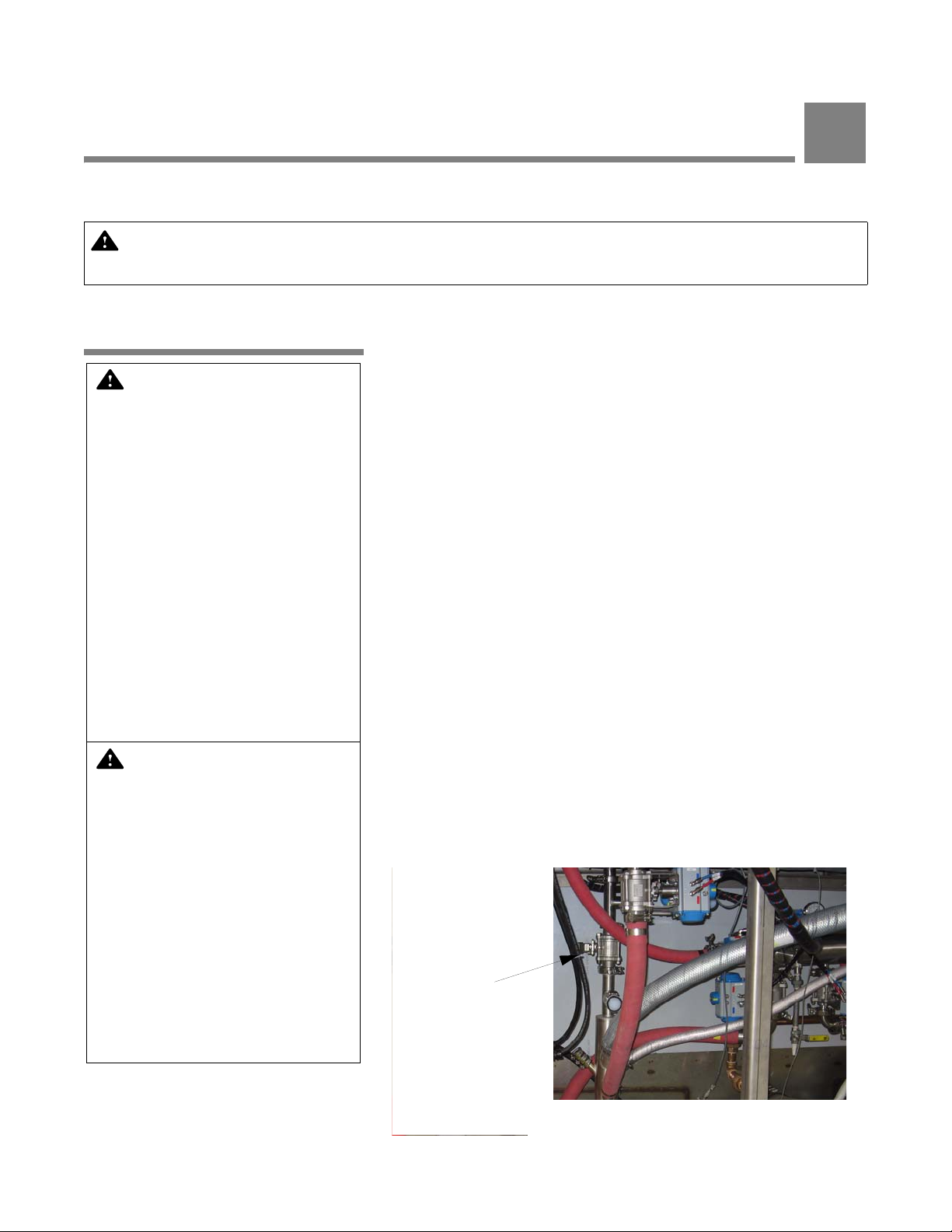
4-1 Manual Drain Valve ............................................................................................................................. 4-1
4-2 Accessories ......................................................................................................................................... 4-3
4-3 Manual Control Mode Flow Chart ...................................................................................................... 4-23
5 CYCLE PROGRAMMING
5-1. Program Touch Pads ............................................................................................................................ 5-1
6 ROUTINE MAINTENANCE
6-1. Spray Header Flush Plug ..................................................................................................................... 6-6
6-2. Self-Cleaning Screen ............................................................................................................................ 6-7
6-3. Exhaust Fan Grease Fittings ................................................................................................................ 6-9
6-4. Manual Drain Valve ............................................................................................................................ 6-10
6-5. Replace Squeeze Tube ...................................................................................................................... 6-13
6-6. Replacing Detergent Container........................................................................................................... 6-14
6-7. Printer Paper Roll Replacement ......................................................................................................... 6-16
vi
Table of Contents Operator Manual 122997-341

SAFETY PRECAUTIONS
The following Safety Precautions must be observed when operating or servicing this equipment. WARNING indi-
cates the potential for personal injury and CAUTION indicates the potential for damage to equipment. For empha-
sis, certain Safety Precautions are repeated throughout the manual. It is important to review ALL Safety
Precautions before operating or servicing the unit.
1
WARNING – PERSONAL INJURY AND/OR EQUIPMENT DAMAGE HAZARD:
Always wear appropriate Personal Protective Equipment (PPE) when cleaning or removing debris from
bottom of wash chamber and over suction plate.
Only STERIS or STERIS-trained service personnel should make repairs and adjustments to this equipment. Maintenance done by inexperienced, unqualified personnel or installation of unauthorized parts
could cause personal injur y, invalida te warranty, or result in costly damage. Contact STERIS regarding
Service options.
Regularly scheduled preventive maintenance, in addition to faithful performance of minor maintenance
described within this manual, is required for safe and reliable operation of this equipment. Contact
STERIS to schedule preventive maintenance.
To open doors from inside wash chamber, pull EMERGENCY STOP cables. Washer operation will
automatically stop. Then, push firmly on door panel using shoulder and u pper arm, applying upper bod y
force.
WARNING – PERSONAL INJURY HAZARD:
Items in washing cart may move du ring processing and be filled with residual hot w ater or protrude from
cart at the end of the cycle. Always wear appropriate personal protective equipment (PPE) and carefully
remove it ems from cart.
Never perform cleaning of wash chamber until full cycle has been completed. If cycle has not been
completed, contaminated debris or water may remain in the bottom of the wash chamber.
Keep fingers away from door hinges to prevent pinching.
To prevent tipping, place biggest and heaviest items on the lower levels of accessory cart.
WARNING – ELECTRIC SHOCK AND/OR BURN HAZARD:
Disconnect all utilities to washer before servicing. Do not service washer unless all utilities have been
properly locked out. Always follow local occupational health and safety regulations, as well as electric
and plumbing codes.
Safety Precautions Operator Manual 122997-341
1-1

WARNING – CHEMICAL BURN AND/OR EYE INJURY HAZARD:
Washer chemicals are caustic an d can cause ad v erse ef f ect s to exposed tissues. Do not get in eyes , on
skin, or attempt to swallow. Read and follow precautions and instructions on chemical label and in
Material Safety Data Sheet (MSDS) prior to handling deter gen t conta iner s, or servicing detergent injection pumps, tank, and lines . W ear appropriate Personal Protective Equipment (PPE) whenever handling
chemicals or servicing chemical injection pumps, tank, and lines.
Wear appropriate Personal Protective Equipment (PPE) when removing clamps and replacing squeeze
tubes. Residual chemicals might remain in used squeeze tubes. If chemical contacts skin or eyes,
immediately flush with running water for at least 10 minutes. If contact was with eyes, seek medical
attention.
Wear gloves and eye protection when using a descaling product. Avoid contact with eyes or skin. If
spilled or splashed, flush with plenty of water for 15 minutes. If swallowed, DO NOT induce vomiting.
Administer an alkali with plenty of water. Seek medical attention immediately.
WARNING – BURN HAZARD:
Allow unit to cool down before performing any service on mechanical components and on piping. Components and piping become very hot during operation.
Inner surfaces of washer are very hot after cycle completion. Ope rator should wear appropriate Personal Protective Equipment (PPE) and avoid all contact with inner walls when entering chamber to
unload washer.
Pipes may be extremely hot.
When cycle is complete, partially open chamber door and allow chamber and load to cool. Hot steam
may escape through door opening if door is fully opened after a cycle.
WARNING – SLIPPING HAZARD:
To avoid slippery floor conditions, k eep floor d ry. Promptly wipe up any spilled liquids or condensation. If
spilled liquids are detergents or other chemicals, follow safety precautions and handling procedures set
forth on detergent or chemical label and/or Material Safety Data Sheet (MSDS).
CAUTION – POSSIBLE EQUIPMENT DAMAGE:
Always use non-foaming chemical for effective cleaning and proper pump and water lev el contr ol oper ation. Follow manufacturer’s recommendations for amount of chemical to be used.
Always use a silicone lubricant to lubricate squeeze tubes. Petroleum-based lubricants, such as
Vaseline
Avoid product damage. Always select a cycle appropriate for items being processed.
1
Vaseline is a trademark of Chesebrough Pond's Incorporated.
®1
or grease, will cause squeeze tubes to melt.
1-2
122997-341 Operator Manual Safety Precautions

CAUTION – POSSIBLE EQUIPMENT DAMAGE (Cont’d):
Before operating unit, always position manifolded Bottle Washing Cart over central water inlet connector. If manifolded accessory is not positioned correctly, damage may result and unit will be unable to
effectiv ely wash load.
Do not process load using Bottle Washing Cart when Automatic Floor Tiltin g o ption is act ivated. If Automatic Floor Tilting is used, manifolded water inlet and washer will be damaged.
Remove all cellulose-type bedding from cages and pans before processing. Cellulose bedding can clog
filters and piping.
Use nonabrasive cleaners when cleaning unit. Follow directions on containers and rub in a back-andforth motion (in same direction as surface grain). Abrasive cleaners will damage stainless steel. Cleaners rubbed in a circular motion applied with a wire brush or steel wool will scratch and dull stainless
steel. Do not use these cleaners on painted surfaces.
When choosing a detergent, select one with a low chloride conte nt. Detergents wi th a high chlo ride content can corrode stainless steel.
Safety Precautions Operator Manual 122997-341
1-3
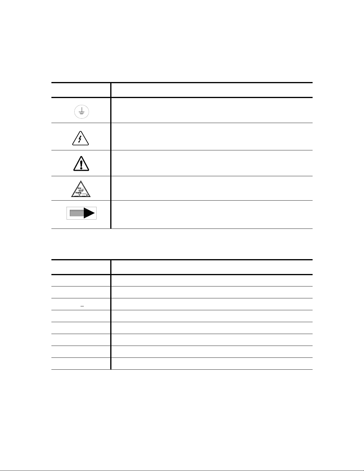
The tables below contain symbols which may be on your Basil 4600 Cage and Rack Washer or 4602 Cage and
Rack Washer components:
Table 1-1. Definition of Symbols on Unit
Symbol Definition
Protective Earth (Ground).
Warning! Risk of Electrical Shock.
Attention! Refer to Manual for Further Instructions.
Fuse Identification.
Pump Rotation
Table 1-2. Definition of Symbols on Identification Nameplate
Symbol Definition
MODEL Model Number of the Unit.
S/N Serial Number of the Unit.
V 3
~ Volt, Number of the Phase (Three) Alternating Current.
WIRE Number of Wires of the Unit, Ground not Included.
YEAR Year of Manufacture of the Unit.
kW Power Rating of the Unit
A Amperage.
Hz Hertz – Frequency of the Unit.
1-4
122997-341 Operator Manual Safety Precautions

2
INSTALLATION CHECKLIST
IMPORTANT: A listing of the Safety Precautions to be observed when operating and servicing this Cage
and Rack Washer can be found in S
this information.
2.1 General An equipment drawing, showing all utility and space requirements,
ECTION 1. Do not install equipment until you have become familiar with
was supplied with the washer. Clearance space specified on equipment drawing is necessary for ease of installation and to assure
proper operation and maintenance of equipment. If documents are
missing or misplaced, contact STERIS giving unit serial, equipment,
and model numbers. Replacement copies will be sent to you
promptly.
2.1.1 Technical specifications
2.1.2 Amperage and Power Consumption
These specifications are intended to describe technical information
given on nameplate of your washer and to state other relevant information. Check equipment drawing or identification nameplate,
located inside control door, above main electrical box, for proper
voltage and amperage.
Basil® 4600 Cage and Rack Washer and Basil® 4602 Cage and
Rack Washer operate on:
• 208 V~, three-phase, 60 Hz
• 480 V~, three-phase, 60 Hz.
A protective ground conductor is required (Class 1 Equipment).
Installation Category is Overvoltage II.
Refer to equipment drawing (920-505-383 for Basil 4600; 920-505-
871 for Basil 4602 or custom equipment drawing) for proper connection.
IMPORTANT: Customer is responsible for compliance with
applicable codes and regulations.
Maximum currents and power consumptions, are indicated on
nameplate.
Installation Checklist Operator Manual 122997-341
2-1

2.1.3 Permissible
Figure 2-1. Shutoff Valves and
Disconnect Switch
Shutoff Valves
Disconnect Switch
Environmental Conditions
2.1.4 Noise Level Equivalent Sound Pressure Level: 84 dB (A). Results determined
This unit is designed to give optimal results under the following con-
ditions:
- Indoor use only;
- Altitude of operation up to 6562 ft (2000 m);
- Temperature 41°F to 104°F (5°C to 40°C);
- Maximum relative humidity is 80% for temperatures up to 88°F
(31°C) decreasing linearly to 50% relative humidity at 104°F
(40°C);
- Installation Category II;
- Pollution Degree 2.
according to ISO-3746: 1995 Standard: Acoustics Determination of
Sound Power Levels of Noise Sources Survey Method.
2.1.5 Seismic Anchorage
2.2 Installation Checklist
Washer can be built to seismic zone 3 and 4 requirements.
System
After installing washer according to Uncrating/Installation Instructions (P910000-015), complete the following checklist to assure
complete and correct installation. Contact STERIS to schedule a
technician to test your installation and demonstrate proper equipment operation.
❑ Shutoff valves (not provided by STERIS) should be installed on
steam and water supply lines to unit (see Figure 2-1). Shutoff
valves must be capable of being locked in OFF position only and
in compliance with occupational health and safety regulations,
as well as electric and plumbing codes for any special requirements that may pertain to installation of this unit.
❑ Disconnect switches (not provided by STERIS) should be
installed in electric supply lines near unit (see Figure 2-1). Disconnect switches must be capable of being locked in OFF position only. Disconnect switches must be installed in electric
supply line near unit (within 10' [3 m] of equipment) and in compliance with occupational health and safety regulations, as well
as electric and plumbing codes for any special requirements
that may pertain to installation of this unit.
2-2
122997-341 Operator Manual Installation Checklist
NOTE: If washer is installed next to other equipment, shutoff valves
and disconnect switch should be placed so that service can be shut
off to any one unit.

❑ Washer is positioned, as shown on equipment drawing, with
required service clearance space and in relation to building supply lines.
❑ Basil 4600 Cage and Rack Washer and Basil 4602 Cage and
Rack Washer must be installed between two walls, with a key-
locked service door, so washer service side is not accessible to
operator.
❑ Building steam line provides maximum dynamic steam pressure
and flow rate to washer as specified on equipment drawing.
❑ Drip leg with steam trap installed in steam supply line.
❑ Building hot water line supplies water to washer at pressure and
temperature specified on equipment drawing.
❑ Building cold water line supplies water to washer at pressure
specified on equipment drawing.
❑ Electrical supply for washer is as specified on equipment draw-
ing.
❑ Condensate returns are sized as specified on equipment draw-
ing.
❑ Vent connections are sized as specified on equipment drawing.
❑ Recirculation pump pressure is within 25 to 60 psig.
❑ Recirculation pump motor rotating in direction shown by arrow.
❑ Self-cleaning screen assembly functioning properly.
❑ Carriage drive motor rotating in direction shown by arrow.
❑ Carriage drive system functioning properly.
❑ Carriage drive motor amperage within rating indicated on the
motor.
❑ Optional exhaust fan rotating in direction shown by arrow.
❑ All piping is leak-free.
❑ Chamber sump steam coil functioning properly.
❑ Door safety switch(es) functioning properly.
❑ Cabinet joints are completely sealed, no leaks (for verification,
run machine for 1/2 hour).
❑ Door(s) easily opens from inside of chamber.
❑ Safety cables immediately stop washer operation when pulled.
❑ Each gear box plastic cap removed and replaced with air vent
provided.
❑ Floor surrounding unit has non-slip surface.
IMPORTANT: After a few weeks of operation, inspect unit for leaks.
Retighten all clamps and connections.
Installation Checklist Operator Manual 122997-341
2-3

2.3 Chemical Additives Specifications
The selection of chemical additives is open for customer preference;
however, in order to achieve optimal performance, the selected
chemical additives must meet as a minimum, the following specifications:
Use Dilution
Product
Description
Range oz/
gal (mL/L)
Dilution
Alkaline
Chemicals
Acidic
Chemicals
Descalers 1/2 -2 <2.5
1/4 - 4
(2-32)
1/4 - 4
(2-32)
pH
Range
at Use
9.0 - 12.0
3.0 - 6.0
Other Applicable
Requirements
Liquid, non-foaming, and viscosity below 200 SSU
(0.0004623 ft2/sec).
Liquid, non-foaming, free
rinsing, and viscosity below
200 SSU (0.0004623 ft2/sec).
Liquid, non-foaming, phosphoric acid-based, and viscosity below 200 SSU
(0.0004623 ft2/sec).
NOTE: When choosing and using chemicals, take note of the following:
1) Follow chemical label recommendations for concentration of
chemical to use.
2) Follow chemical manufacturer's recommendations to determine
the temperature of the WASH treatment .
3) Follow chemical manufacturer's recommendations for the amount
of chemical used according to water hardness.
To achieve maximum cleaning efficiency, select chemical appropriate to soil type being processed. STERIS recommends the following
chemicals:
®
• Cage-Klenz
100 Alkaline Cage Wash Detergent -
(Alkaline) formulated to remove urine, scale, animal fats, oils and
other organic soils from cage materials.
®
• Cage-Klenz
200 Acid-Based Cage Wash Detergent -
(Acidic) formulated to remove urine, scale, animal fats, oils and
other organic soils from cage materials.
• Liquid Descaler Acid-Based Scale Remover - for
removing scale and other hard water deposits. For use in animal
care centers.
NOTE: Certain products may not be available in your area. Contact
your STERIS representative for availability of these products and for
ordering information.
IMPORTANT: STERIS does not promote, recommend, nor endorse
the use of any other type of chemical additives in the processing of
articles in the Basil 4600/4602 Cage and Rack Washers, such as
drying agents, strong alkaline detergents (pH>12), alcohol rinses and
liquid germicides including hypochloric acid (bleach).
2-4
122997-341 Operator Manual Installation Checklist
3
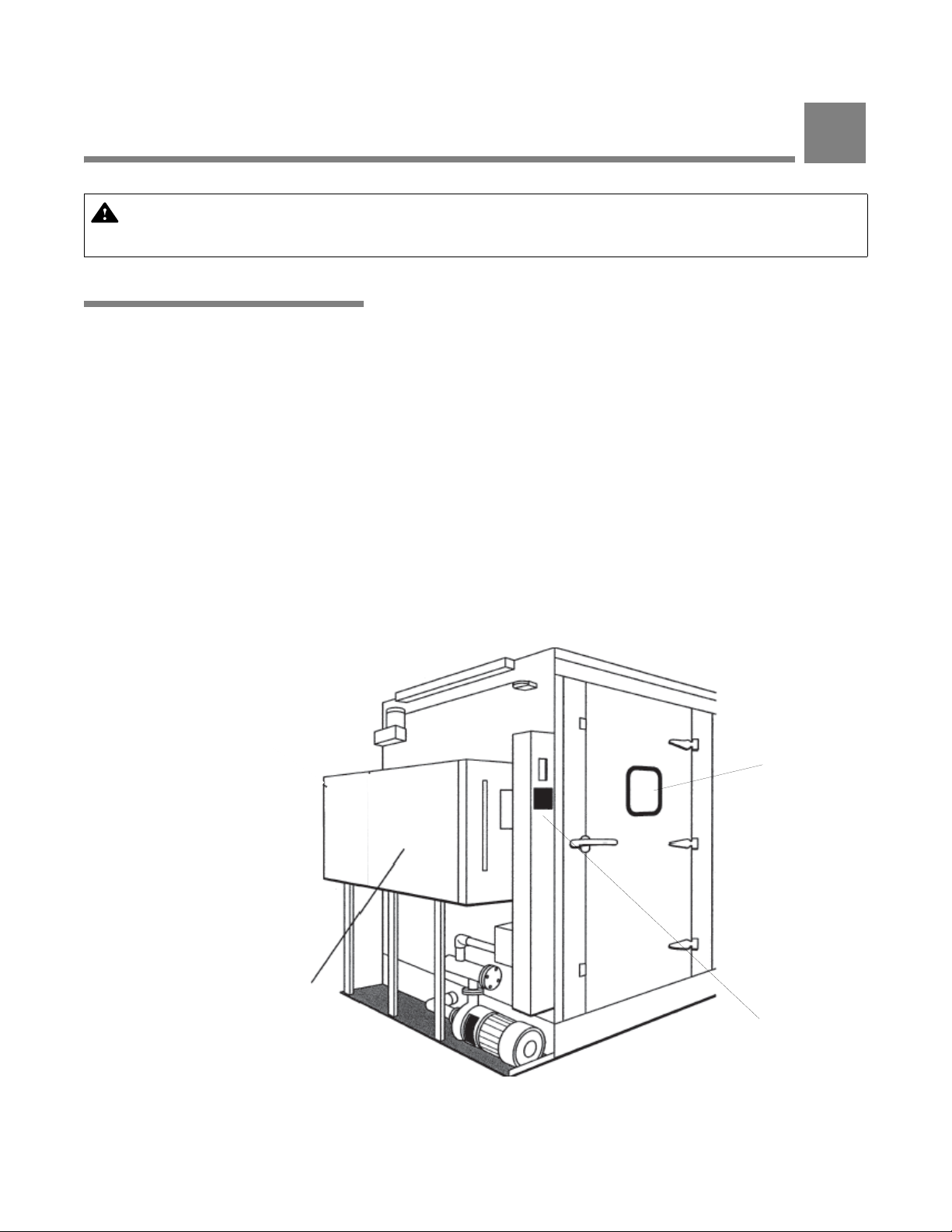
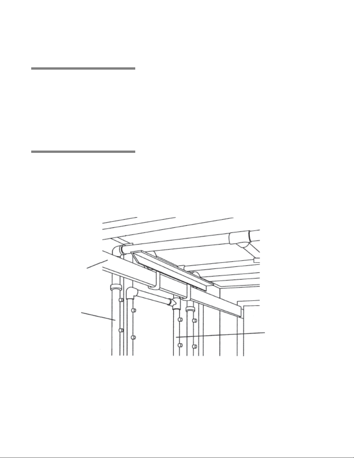
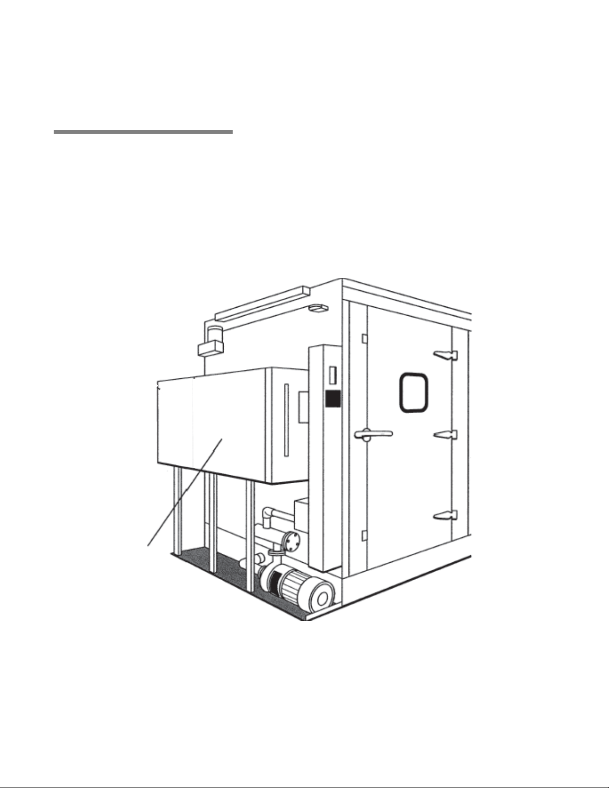
Figure 3-1. Washer Components - Basil 4600 (Typical)
Reusable-Throwaway
Detergent Tank
Chamber Door
and Viewing
Window
Control Console
COMPONENT IDENTIFICATION
IMPORTANT: A listing of the Safety Precautions to be observed when operating and servicing this Cage
and Rack Washer can be found in S
this information.
3.1 General Become familiar with location and function of all major components
ECTION 1. Do not install equipment until you have become familiar with
and controls, as well as their function before operating this unit (see
Figure 3-1).
Two models are available: Basil
®
4602 Cage and Rack Washer.
Basil
•Basil
4600:
Wash Chamber: 46" W x 85" H x 92" L (1168 x 2159 x 2336 mm)
Overall Unit: 82" W x 102" H x 99" L (2082 x 2590 x 2514 mm)
Equipped with Reusable - Throwaway Detergent Tank
• Basil 4602:
Wash Chamber: 46" W x 85" H x 188" L (1168 x 2159 x 4775 mm)
Overall Unit: 82" W x 102" H x 195" L (2082 x 2590 x 4953 mm)
Equipped with Reusable - Throwaway Detergent Tank
Each model is equipped with a user-programmable microcomputer
control system capable of storing up to twelve treatment cycles to
process a wide variety of loads. Computer control system monitors
and automatically controls all cycle operations.
®
4600 Cage and Rack Washer and
3-1
Component Identification Operator Manual 122997-341
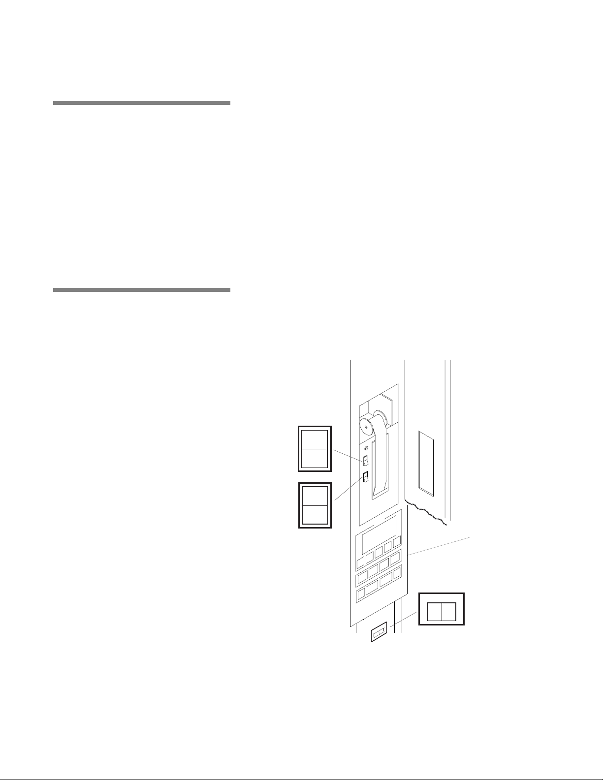
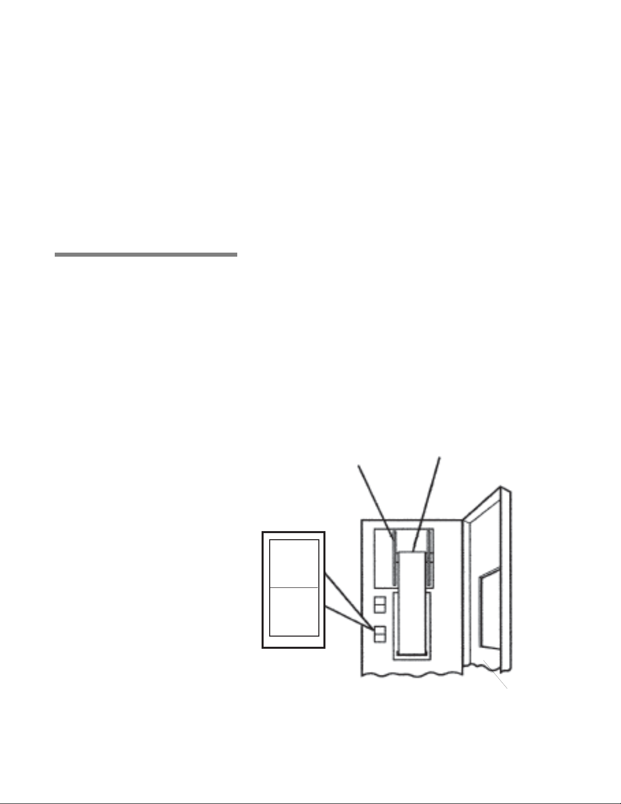
3.2 POWER-OFF/
POWER
OFF
STANDBY
PRINT
PRINT
VALUES
ON
OFF
INTERIOR LIGHT
Figure 3-2. Control Column
Control Panel
STANDBY Switch
POWER-OFF/STANDBY switch, located behind the printer door,
includes two settings which direct operation of control (see Figure 3-
2):
• POWER – Press top portion of POWER-OFF/STANDBY switch to
initialize control and place control in Ready Mode.
• OFF/STANDBY – Press bottom portion of POWER-OFF/
STANDBY switch to initiate Shutdown Cycle and place control in
Standby Mode.
NOTE: Control should be placed in Standby Mode for last cycle of th e
day and when washer is not in use for an extended peri od of time.
IMPORTANT: POWER-OFF/STANDBY switch does not turn off
electrical power to unit.
3.3 Interior Light Interior light, can be manually controlled by operator through a tog-
gle switch located behind printer door, below control panel, on load
side (see Figure 3-2). Interior light illuminates wash chamber when
loading or unloading washer, or it can left ON during a whole washing cycle to view washing process.
3-2
122997-341 Operator Manual Component Identification
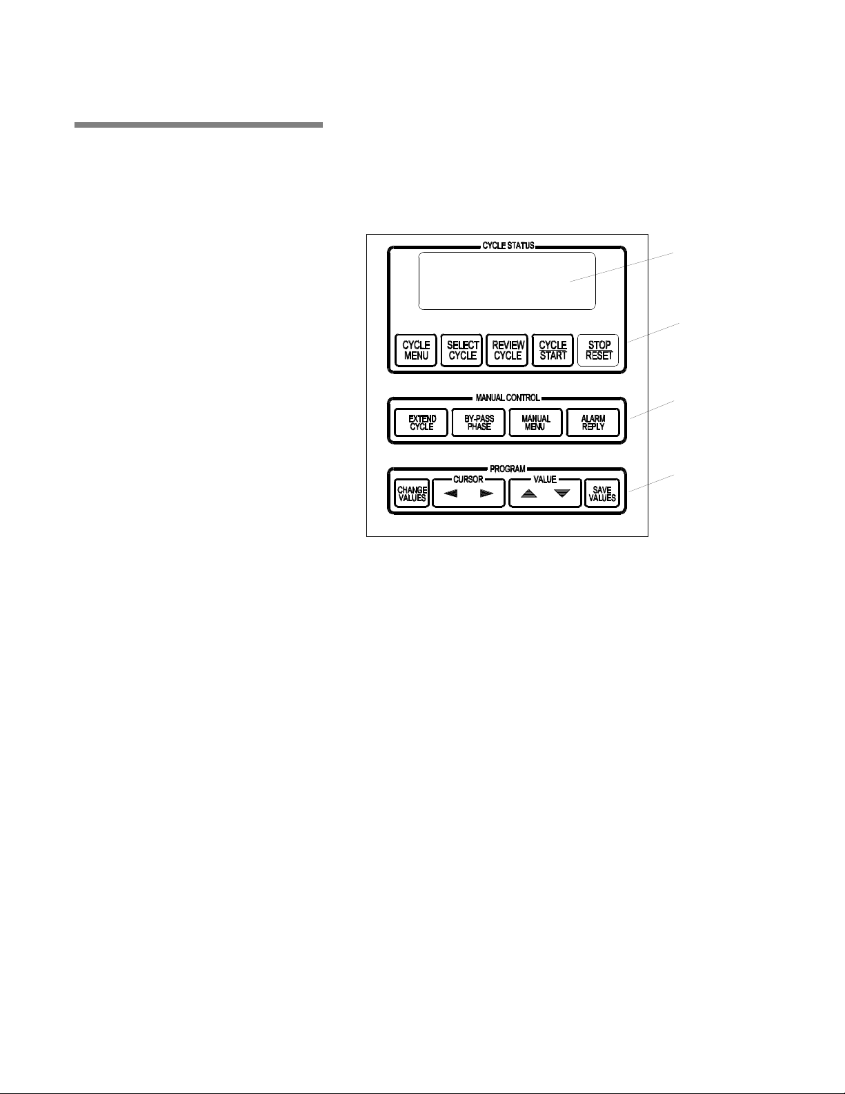
3.4 Control Panel Control Panel is used to direct all washer functions (see Figure 3-3).
Figure 3-3. Control Panel
Display Screen
Cycle Status
Touch Pads
Manual Control
Touch Pads
Program Touch
Pads
Operator may program specific cycles, review and select cycles,
start, stop or reset cycle operation, extend or bypass cycle phases,
and monitor cycle performance.
3.4.1 Display Screen Two line alpha-numeric screen displays cycle program data on
demand, in-cycle performance data and operator instructions. Display screen also indicates certain abnormal conditions that may
occur during a cycle.
3.4.2 Cycle Status Touch Pads
Component Identification Operator Manual 122997-341
• CYCLE MENU touch pad – press to view first cycle menu. Press
again to advance screen to next cycle menu. Three menus are
available, each with four cycles.
• SELECT CYCLE touch pad – press until desired cycle name
flashes.
NOTE: When a displayed cycle name or phase value is selected,
corresponding word or digit flashes.
• REVIEW CYCLE touch pad – press to review cycle phases and
values programmed for selected cycle.
• CYCLE/START touch pad – press once to display name of
selected cycle. Press a second time to start cycle.
NOTE: Selected cycle name remains on screen for 5 seconds
3-3

after pressing CYCLE/START touch pad once. To start a cycle,
CYCLE/START touch pad must be pressed a second time while
selected cycle name is displayed. If touch pad is not pressed
within 5 seconds, screen automatically returns to Cycle Menu.
• STOP/RESET touch pad – press once to stop cycle operation.
Press a second time to abort cycle and return screen to cycle
menu.
NOTE: When cycle is stopped, press Cycle/Start touch pad once to
resume cycle operation. Cycle operation resumes at beginning of
interrupted phase function (i.e., filling, recirculating, draining). When
cycle is aborted, cycle operation is discontinued and cycle must be
re-started from the beginning.
3.4.3 Manual Control Touch Pads
• EXTEND PHASE touch pad – press to temporarily increase
selected phase time. On completion of cycle, phase time returns
to programmed setpoint.
• BYPASS PHASE touch pad – press to bypass specific phase in
progress and advance cycle to next phase.
NOTE: Bypass Phase touch pad can only be used when a cycle
is in progress. During cycle, filling and draining functions can not
be bypassed. In addition, a phase can not be bypassed if
Temperature Guarantee feature is selected for that phase.
• MANUAL MENU touch pad – press to view washer functions
which can be controlled manually.
• ALARM REPLY touch pad – press to turn off alarm buzzer and
acknowledge displayed alarm message. Refer to S
ROUBLESHOOTING, for specific alarm conditions and corrective
T
ECTION 7,
actions.
3.4.4 Program Touch Pads Program touch pads allow programming of twelve distinct cycles
and changing of previously programmed cycle values to process
different types of loads. Cycle programming may be limited by
access code to ensure process integrity. Refer to S
PROGRAMMING, for details on cycle programming and access code
feature.
• CHANGE VALUES touch pad – press to access Change Values
mode. Change Values mode allows authorized operators to
change user-programmable items. Refer to S
PROGRAMMING, for details about Change Values Mode.
ECTION 5, CYCLE
ECTION 5, CYCLE
NOTE: Examples of user-programmable items include cycle
name, phase temperature, phase time, and questions regarding
phase options (e.g., retention of final rinse water).
3-4
122997-341 Operator Manual Component Identification
• CURSOR (left or right) touch pad – press until item to be
PRINT
PRINT
VALUES
Figure 3-4. Printer
Thermal Paper
Take-Up Spindle
Printer Door
changed (word, letter, or number) flashes.
• VALUE (up or down) touch pad – depending on item flashing
(selected), press to either toggle between answer selections or
scroll through alphabet and numbers 0 through 9.
NOTE: Alphabet includes characters for an underline (_) and a
space ( ).
• SAVE VALUES touch pad – press to save changes made, exit
Change Values mode and return screen to cycle menu.
3.5 Printer Printer records pertinent cycle data on 2-1/4" wide thermal paper
(see Figure 3-4). Refer to S
on changing paper roll and storing thermal paper.
3.5.1 Printer Function Switch Printer Function Switch controls the following two printer functions:
• PRINT – press top of Printer Function Switch to generate a print
of alkaline and acid detergent setpoints (if conductivity option)
and all RTD temperatures (actual water temperature).
• PRINT VALUES – press bottom of Printer Function Switch to
generate a complete printout of all cycle parameters.
ECTION 6.7, PRINTER PAPER, for information
Component Identification Operator Manual 122997-341
3-5

3.5.2 Sample Printout The following is an example of a typical cycle printout (see Figure 3-5):
Figure 3-5.Sample Printout
* CONTROL ON 8:32:31A
- - - - - - - - - - - - - - - - - - - - - - - CYCLE – CYCLE 1
- - - - - - - - - - - - - - - - - - - - - - - -
CYCLE START 8:37:33A
CYCLE DATE 4/24/05
CYCLE NUMBER 00000001
UNIT NUMBER 3600000000
PHASE TIME F
- - - - - - - - - - - - - - - - - - - - - - - - - - - - - - - - PRE-WASH 8:38:03A 141.5
8:39:03A 135.0
DET-WASH 8:41:33A 146.3
8:46:33A 144.2
RINSE 1 8:49:10A 183.5
8:50:40A 182.7
RINSE 2 8:53:00A 184.0
8:54:30A 182.5
F. RINSE 8:57:20A 184.3
8:58:50A 183.8
EXHAUST 8:59:50A 183.8
- - - - - - - - - - - - - - - - - - - - - - - - - - - - - - - - -
CYCLE COMPLETE 9:01:20A
MAX WASH TEMP= 146.3F
MAX RINSE TEMP= 184.3F
CYCKE TIME= 0:23:27
- - - - - - - - - - - - - - - - - - - - - - - - - - - - - - - - READY TO UNLOAD
- - - - - - - - - - - - - - - - - - - - - - - - - - - - - - - - -
DOOR OPENED 9:03:42A
Cycle Start In-Cycle Performance
End-of Cycle Performance
Summary
Figure 3-6. Sample Alarm Printout
PHASE TIME F
- - - - - - - - - - - - - - - - - - - - - - - - - - - - - - - - - - - PREWASH 10:15:20A 163.5
10:17:02A 166.8
* ALARM 10:18:02A
SUMP
TOO LONG IN FILL
- - - - - - - - - - - - - - - - - - - - - - - - - - - - - - - - - - - ALARM ACKNOWLEDGED
AT 10:18:15A
• POWER UP
When POWER-OFF/STANDBY switch is set to POWER,
generated printout lists time and date control was turned on and
unit’s serial number.
• CYCLE START
When CYCLE/START touch pad is pressed twice to begin
selected cycle, generated printout lists name of cycle started,
time and date cycle was started, cycle number, and unit
number.
• IN-CYCLE PERFORMANCE
During a cycle, generated printout lists start and end time of
each phase, along with actual temperature of solution/water in
chamber sump.
• END-OF-CYCLE PERFORMANCE SUMMARY
At end of a cycle, generated printout lists time cycle was
completed, maximum wash and rinse temperatures reached
during cycle, and total cycle processing time.
• ALARM CONDITION
When an alarm condition occurs, generated printout lists type of
alarm and time it occurred (see Figure 3-6). Once operator
presses Alarm Reply touch pad, generated printout lists time
alarm was acknowledged.
3-6
122997-341 Operator Manual Component Identification
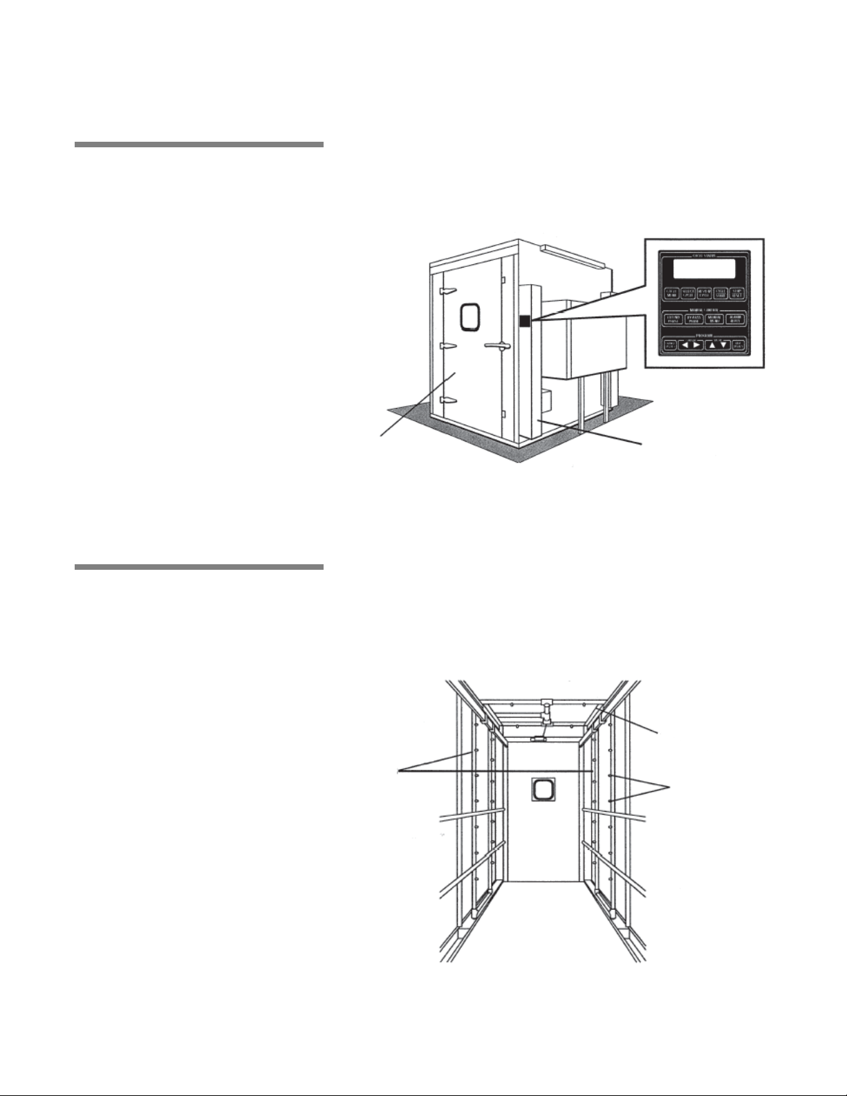
3.6 Unload-Side
Figure 3-7. Unload-Side Control Panel
Second Control
Column
Additional Chamber
Door on Unload Side
Figure 3-8. Oscillating Jet System
Spray Jets
Spray
Headers
Oscillating
Carriage
Control Panel
An additional control column is installed on unload side of unit (see
Figure 3-7). The unload side control panel features same touch pads
and display screen as load end control panel.
All washer functions except POWER-OFF/STANDBY and PRINT/
PRINT VALUES can be directed from this control panel, and display
screen concurrently shows same cycle performance data as loadside control panel.
3.7 Oscillating Jet System
Oscillating jet system consists of two spray headers, one on each
side of wash chamber, suspended from an oscillating carriage (see
Figure 3-8). Each spray header is equipped with machined jets
angled to reach all surfaces of load.
Oscillating jet system travels back and forth along length of chamber
during recirculating/spraying phase function. Jet system is equipped
with a safety clutch that stops movement of oscillating carriage if an
obstruction is detected.
Component Identification Operator Manual 122997-341
3-7
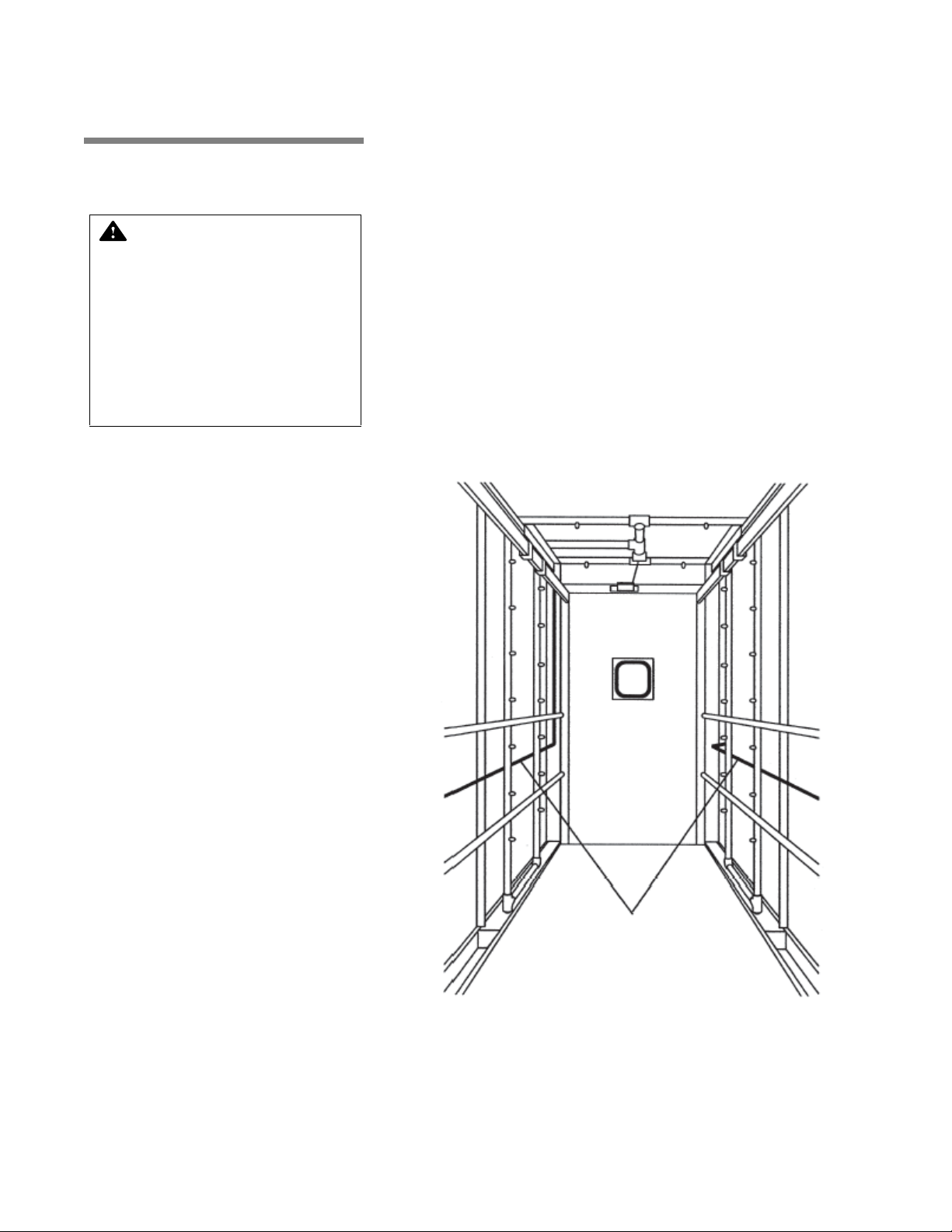
3.8 Safety System Chamber doors are equipped with a safety switch to stop washer
WARNING – PERSONAL
INJURY AND/OR EQUIPMENT DAMAGE HAZARD:
To open doors from inside
wash chamber, pull EMERGENCY STOP cables.
Washer operation will automatically stop. Then, push
firmly on door panel using
shoulder and upper arm,
applying upper body force.
Figure 3-9. Safety Cables
Safety
Cables
operation if door is opened during a cycle and to prevent start of
washer operation if door is not securely closed.
Chamber doors are also equipped with a spring-loaded, explosion
relief type safety latch. Door can be easily opened when pushed
from inside of wash chamber.
Two stainless-steel, red-coated safety cables are installed inside
wash chamber, one along each side (see Figure 3-9). If cable is
pulled, washer operation is immediately stopped.
Oscillating jet system is equipped with a mechanical clutch to disengage carriage drive if an obstruction is encountered, preventing
damage to spray headers and load items.
Load-side and unload-side control panels are equipped with STOP/
RESET touch pads. Press touch pad once to stop cycle operation,
and twice to abort cycle.
3-8
122997-341 Operator Manual Component Identification
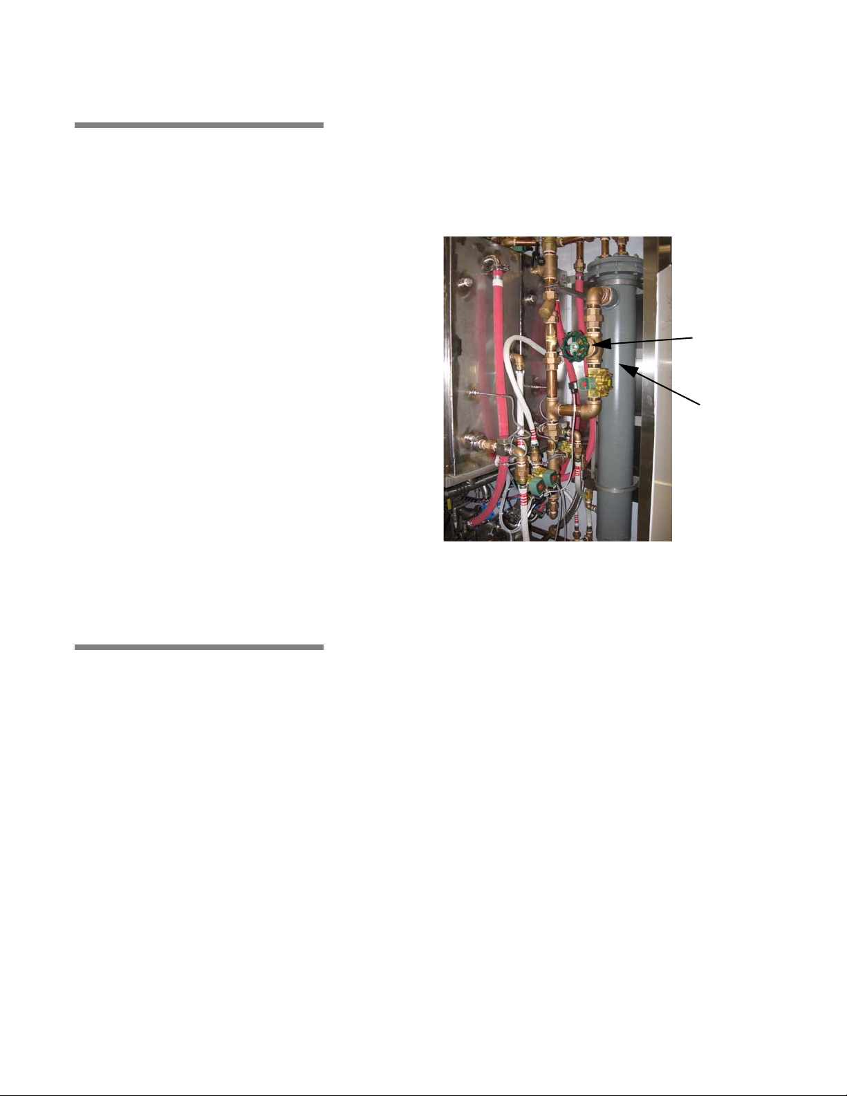
3.9 Heat Exchanger Washer is equipped with a steam heat exchanger and valving sys-
Figure 3-10. Heat Exchanger
Heat
Exchanger
Heat
Exchanger
Steam
Throtling
Valve
tem to preheat incoming fill water, reducing normal water/solution
heat-up time (see Figure 3-10).
System is fully automatic and works during filling function of Prewash, optional Acid Wash (if acid tank is not available), and Rinse
phases. Heat exchanger steam valve is energized only if temperature is below 165°F (73.8°C).
3.10 Automatic
Detergent Injection
System
Automatic Detergent Injection System includes a peristaltic pump
mounted to washer exterior. System also includes a conductivity
probe located in chamber sump.
If using alkaline detergent with injection system, alkaline detergent is
automatically injected into chamber sump during Wash phase of a
cycle.
• Hot detergent solution from alkaline detergent tank fills sump
until required solution level is attained. Once sump is full, control
checks detergent concentration of solution in sump. Alkaline
detergent is then injected into sump until solution reaches set
concentration level. Alkaline detergent solution is monitored and
maintained at set concentration level while recirculating and
spraying over load.
If using acid detergent with injection system, acid detergent is automatically injected into chamber sump during Acid Wash phase of a
cycle.
• Hot detergent solution from acid detergent tank fills sump until
required solution level is attained. Once sump is full, control
checks detergent concentration of solution in sump. Acid
detergent is then injected into sump until solution reaches set
concentration level. Acid detergent solution is monitored and
maintained at set concentration level while recirculating and
spraying over load.
Component Identification Operator Manual 122997-341
3-9
3.11 Reusable-
Figure 3-11. Non-Recirculated Final Rinse Spray Header
Separate Spray Header
for Fresh Water
Carriage Rail
Main Spray Header
Throwaway Acid
Detergent System
Washers equipped with Reusable-Throwaway Acid Detergent System can be programmed to process an Acid Wash phase after
Detergent Wash phase, and to either save or drain acid detergent
solution on completion of phase.
System includes a separate acid detergent tank and piping constructed of stainless steel. Acid detergent tank is equipped with a
steam coil to maintain acid detergent solution at programmed temperature.
3.12 Non- Recirculated Final Rinse
Washers equipped with Non-Recirculated Final Rinse System can be
programmed to spray load with fresh, non-recirculated water during
standard Final Rinse phase. System includes a separate spray
header mounted directly to each side of oscillating carriage, inside
of main spray headers (see Figure 3-11).
3-10
122997-341 Operator Manual Component Identification

3.13 Feeder Bottle Washing System
Feeder Bottle Washing System provides capability of processing a
loaded bottle cart during normal cycle operation. System includes a
quick disconnect coupler.
NOTE: Bottle washing cart is available as a separate accessory.
Cycle must be programmed to process bottle cart before starting
cycle operation.
3.14 Automatic Water
Flush System for Two
Racks
Automatic Water Flush System for two racks permits cleaning of
facility’s automatic watering system during normal cycle operation.
System includes a set of two hoses, each equipped with a quick disconnect fitting, mounted on service side carriage rail.
Hoses are manually connected to customer cage watering racks
moved into wash chamber. During Final Rinse filling, fresh hot water
is sent through heat exchanger and sprayed over cage watering
racks for programmed filling time interval.
Component Identification Operator Manual 122997-341
3-11
3.15 Drain Discharge
Figure 3-12. Drain Discharge Side Tank (Typical)
Drain Discharge Side
Tank
Cooldown with Side
Tank and Temperature
Guarantee
A separate tank is typically mounted along service side of washer to
temporarily retain and cool all drain discharges (see Figure 3-12).
NOTE: Location of drain discharge side tank may change depending
on other options ordered with washer.
During draining function of each phase, solution/water in sump is
automatically pumped to side tank where cold tap water is added.
Cold water remains on until water temperature in side tank reaches
programmed set point. Once cooled to set temperature, side tank
gravity drains to building drain system.
3-12
122997-341 Operator Manual Component Identification
3.16 Drain Discharge
Figure 3-13. Exhaust Fan
Cooldown System with
Cold Water Injection
Only
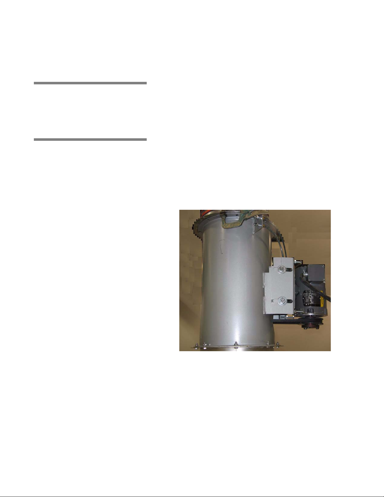
3.17 Exhaust Fan Exhaust Fan is mounted directly in washer exhaust line, on top of unit
Washer drain system is piped to automatically cool all drain discharges using building cold water supply.
During draining function of each phase, cold tap water is injected
into washer drain line as washer drain discharges are sent directly to
building drain system. Cold water remains on until sump drain valve
closes.
(see Figure 3-13).
During unit operation, exhaust fan removes residual vapors from
wash chamber and directs vapors to building exhaust duct.
Component Identification Operator Manual 122997-341
3-13
4
WARNING – CHEMICAL
BURN AND/OR EYE INJURY
HAZARD: Washer chemicals
are caustic and can cause
adverse effects to exposed
tissues. Do not get in eyes,
on skin or attempt to swallow. Read and follow precautions and instructions on
chemical label and in Material Safety Data Sheet
(MSDS) prior to handling
detergent containers, or servicing detergent injection
pumps, tank, and lines. Wear
appropriate Personal Protective Equipment (PPE) whenever handling chemicals or
servicing chemical injection
pumps, tank, and lines.
CAUTION – POSSIBLE
EQUIPMENT DAMAGE:
• Always use non-foaming
chemical for effective
cleaning and proper pump
and water level control
operation. Follow manufacturer’s recommendations for amount of
chemical to be used.
• When choosing a detergent, select one with a low
chloride content. Detergents with a high chl oride
content can corrode stainless steel.
Figure 4-1. Manual Drain Valve
Manual Drain
Valve
WASHER OPERATION
IMPORTANT: A listing of the Safety Precautions to be observed when operating and servicing this Cage
and Rack Washer can be found in S
this information.
ECTION 1. Do not install equipment until you have become familiar with
4.1 Before Operating Washer
Become familiar with location and function of all major components
and controls, as well as their function before operating equipment.
1. Verify building electrical supply disconnect switch (circuit
breaker) is positioned to ON. Verify steam and water supply
valves are open.
2. Open chamber door. Verify chamber is empty and all material
has been removed.
3. Verify debris screens in bottom of sump are clean and properly
installed.
4. Open printer door and check sufficient amount of printer paper
is available.
NOTE: A colored warning stripe is visible when printer paper roll
is near the end. Refer to S
needed.
5. Ensure manual drain valves on bottom of detergent tanks and, if
applicable, optional acid detergent tank are closed (see Figure
4-1).
6. Verify detergent supply (provided by customer). Check sufficient
amount of detergent is available (Refer toS
ING DETERGENT CONTAINER). Ensure supply hose(s) is correctly
placed in detergent container(s) and detergent pump(s) is
turned on.
NOTE: Always use a non-foaming detergent for effective cleaning
and proper pump and water level control operation. To achieve
maximum cleaning efficien cy, sele ct det ergent appro priate to soil
type being processed.
ECTION 6.7, PRINTER PAPER, if paper is
ECTION 6.6.5, REPLAC-
Washer Operation Operator Manual 122997-341
4-1
4.2 How to Load
WARNING – PERSONAL
INJURY HAZARD:
• Keep fingers away from
door hinges to prevent
pinching.
• To prevent tipping, place
biggest and heaviest items
on the lower levels of accessory cart.
WARNING – BURN HAZARD:
When cycle is complete, partially open chamber door and
allow chamber and load to
cool. Hot steam may escape
through door opening if door
is fully opened after a cycle.
WARNING – SLIPPING HAZARD: To avoid slippery floor
conditions, keep floor dry.
Promptly wipe up any spilled
liquids or condensation. If
spilled liquids are detergents
or other chemicals, follow
safety precautions and handling procedures set forth on
detergent or chemical label
and/or Material Safety Data
Sheet (MSDS).
CAUTION – POSSIBLE EQUIPMENT DAMAGE:
• Avoid product damage.
Always select a cycle appropriate for items being processed.
• Before operating unit,
always position manifolded
Bottle Washing Cart over
central water inlet connector. If manifolded accessory
is not positioned correctly,
damage may result and unit
will be unable to effectively
wash load.
• Do not process load using
Bottle Washing Cart when
Automatic Floor Tilting
option is activated. If Automatic Floor Tilting is used,
manifolded water inlet and
washer will be damaged.
CAUTION – POSSIBLE EQUIPMENT DAMAGE:
Remove all cellulose-type bedding from cages and
pans before processing. Cellulose bedding can clog
filters and piping.
Washer
To properly clean items and avoid personal injuries, always follow
these general guidelines:
1. Remove gross soil before processing in washer.
2. Use appropriate accessory racks within cart to load items such
as bottles.
3. Assure no items stick out or hang out of the accessory cart.
4. Place biggest and heaviest items on the lower levels of acces-
4-2
122997-341 Operator Manual Washer Operation
sory cart.
5. As an example, proper placement of items in Washing Cart
would be as follows, from the top down
Accessories (see Figure 4-2):
• Bottle Washing Cart – Used for processing up to six bottle
baskets. Requires Manifold Coupling System.
• Pan Cart – Used to wash pans, floor gratings, cage doors,
etc.
• Universal Cage and Wash Cart – Used to wash 54 stan-
dard mouse boxes or 36 standard rat boxes.
• Rodent Cage Rack – Used to hold up to 92 mouse cages or
32 rat cages, or shoe boxes, covers, and feeder tops.
IMPORTANT: Use baskets for handling and cleaning various
size bottles. Lightweight basket design provides easy
handling and simplifies transport and washing of bottles.
• 5 x 5 Bottle Basket – Used to wash 25,16 oz (454 mL) bottles.
• 4 x 6 Bottle Basket – Used to wash 24, 16 oz (454 mL) bottles.
• 5 x 5 Bottle Basket – Used to wash 25 short 4" (10 cm) bottles.
• 4 x 6 Bottle Basket – Used to wash 24 tall 5-1/2" (14 cm) bot-
tles.
6. Open chamber door and push loaded wash cart(s) into wash
chamber.
a. Ensure all cages, racks, etc. are correctly positioned on
wash cart(s).
b. Position cart(s) in center of wash chamber. Verify clearance
space on both sides of cart permits unobstructed movement
of oscillating jet system.
7. Close and latch chamber doors securely.
NOTE: Door safety switch prevents cycle operation unless
door(s) is closed.
8. Start desired cycle.

Washer Operation Operator Manual 122997-341
4-34
122997-341 Operator Manual Washer Operation
Rodent Cage Rack
Universal Cage and Pan Wash Cart
Bottle Washing Cart (Typical)
Pan Cart
Figure 4-2. Accessories
4-3

4.3 Cycle Operation Basil
Table 4- 1. Demo ns t rati o n Cycle
Phase Values
Cycle
Phase
Time
(minutes)
Temperature
Pre-
Wash
1:00 HTW
Wash 5:00 140ºF (60ºC)
Rinse 1 1:30 180ºF (82ºC)
Rinse 2 1:30 180ºF (82ºC)
Final
Rinse
1:30 180ºF (82ºC)
Exhaust 1:30 N/A
SELECT
CYCLE
CYCLE
START
CYCLE
START
Rack Washer are equipped with a microcomputer control capable
of storing parameters for twelve distinct cycles. Authorized operators
have capability of customizing/programming all cycles to meet specific washing needs. For instructions on cycle programming or
changing cycle parameters, refer to S
On initial receipt of washer, each cycle is set with a basic demonstration cycle consisting of six sequential phases – Pre-wash, Wash,
Rinse 1, Rinse 2, Final Rinse and Exhaust. Refer to Table 4-1 for
phase values of demonstration cycle.
To begin cycle operation:
1. Set POWER-OFF/STANDBY switch, located behind printer door,
®
4600 Cage and Rack Washer and Basil® 4602 Cage and
ECTION 5, CYCLE PROGRAMMING.
to POWER.
Unit name temporarily appears on screen, then screen displays
first cycle menu:
CYCLE 1
CYCLE 2
CYCLE 3 CYCLE 4
__indicates flashing position.
and printer records:
* CONTROL ON 8:32:31A
4/21/05
NOTE: If printer does not print when POWER-OFF/STANDBY
switch is set to POWER, press top of Printer Function Switch to
turn printer on.
2. Press CYCLE MENU touch pad until desired cycle menu
appears on screen. Display shows:
CYCLE 9
CYCLE 10
CYCLE 11 CYCLE 12
__indicates flashing position.
3. Press SELECT CYCLE touch pad until desired cycle name
flashes.
CYCLE 9 CYCLE 10
CYCLE 11 CYCLE 12
__indicates flashing position.
4. When desired cycle name is flashing, press CYCLE/START
touch pad. Name of selected cycle appears on screen and
remains displayed for five seconds.
PRESS START TO
PROCESS CYCLE 10
5. To start selected cycle, press CYCLE/START touch pad a sec-
ond time while selected cycle name is displayed on screen.
NOTE: If CYCLE/START is not pressed a second time while
selected cycle name is displayed, screen automatically returns to
cycle menu.
4-4
122997-341 Operator Manual Washer Operation

Once selected cycle is started, printer records:
CYCLE - CYCLE 10
_ _ _ _ _ _ _ _ _ _ _ _ _ _ _ _ _ _ _ _
CYCLE START 8:37:33A
CYCLE DATE 4/24/05
CYCLE NUMBER 00000001
UNIT NUMBER 3600000000
PHASE TIME F
6. Washer automatically progresses through selected cycle as follows:
NOTE: For cycle operation, note the following:
1) Time displayed on screen counts down time remaining for cycle
phase in progress. If Temperature Guarantee feature is selected,
time displayed for that phase only counts down when solution/
water temperature in chamber sump is equal to or greater than
setpoint.
2) Cycle operation may be halted at any time by pressing STOP/
RESET touch pad once. To resume cycle operation at be gin n ing
of interrupted phase function (i.e., fill, recirculate, drain), press
CYCLE/START. To abort cycle operation, press STOP/RESET a
second time.
• PRE-WASH PHASE
>> Hot water, from building supply, fills sump until required
water level is attained.
NOTE: Sump may contain rinse water retained from previous
cycle.
Display shows:
CYCLE 10 135.7f
PREWASH FILL T=2:00
>> Pre-wash water recirculates through oscillating jet system for
programmed time interval. Display shows:
CYCLE 10 139.5F
PREWASH T=1:00
Printer records time and water temperature in chamber sump at
beginning and end of recirculation:
PREWASH 10:18:15A 139.5
10:19:15A 135.0
• pH NEUTRALIZATION (Option)
>> pH analyzer is initialized. Display shows:
STANDBY NEUTRALIZING SUMP
Washer Operation Operator Manual 122997-341
4-5

>> pH analyzer checks to see if value is within limits. Display
shows:
CHECKING pH
pH = XX.XXX
>> If pH is too low while injecting, acid Neutralizer is injected
to compensate. Display shows:
pH TOO LOW
INJECTING ACID NEUT.
>> Water-Acid neutralizer solution is mixed. Display shows:
pH TOO LOW
MIXING WATER
>> If pH is too high while injecting, alkaline neutralizer is
injected to compensate. Display shows:
PH TOO HIGH
INJECTING ALK. NEUT.
>> Water-Alkaline neutralizer solution is mixed. Display shows:
pH TOO HIGH
MIXING WATER
>> Water contained in traveling spray header is sent to sump
(all units). Display shows:
CYCLE 10 128.5F
HEADER DRAIN T= 1:00
>> Sump water is pumped to drain. Display shows:
CYCLE 10 128.5F
PREWASHDRAIN T= 1:00
>> Water still present in sump is gravity-drained (option).
Displays shows:
CYCLE 10 128.5F
GRAVITY DRAIN T= 1:00
• ALKALINE WASH PHASE
>> Hot water, from alkaline wash tank, fills sump. If temperature
is guaranteed, actual sump temperature alternates with
guaranteed set temperature. Display shows:
CYCLE 10 (G=)137.4F
ALK. WASH FILL T= 2:00
NOTE: Control alternates between these display screens every
four seconds during recirculation. Displayed time only counts
down when solution temperature is equal or greater than
setpoint.
>> Water is heated while recirculating (CONDUCTIVITY
OPTION ONLY). If temperature is guaranteed actual sump
temperature alternates with guaranteed set temperature.
Display shows:
4-6
122997-341 Operator Manual Washer Operation

CYCLE 10 (G=)141.5F
RECIRC./HEATING T= 5:00
NOTE: Control alternates between these display screens every
four seconds during recirculation. Displayed time only counts
down when solution temperature is equal or greater than
setpoint.
>> Alkaline detergent is injected into sump. If temperature is
guaranteed, actual sump temperature alternates with
guaranteed set temperature. Display shows:
CYCLE 10 (G=)141.5F
INJECTING ALK. T= 5:00
NOTE: Control alternates between these display screens every
four seconds during recirculation. Displayed time only counts
down when solution temperature is equal or greater than
setpoint.
>> Detergent solution is recirculated through oscillating jet
system for programmed amount of time. If temperature is
guaranteed, actual sump temperature alternates with
guaranteed set temperature. Display shows:
CYCLE 10 (G=)140.4F
ALKALINE WASH T= 5:00
NOTE: Control alternates between these display screens every
four seconds during recirculation. Displayed time only counts
down when solution temperature is equal or greater than
setpoint.
Printer records time and solution temperature in chamber sump
at beginning and end of recirculation:
ALK. WASH 10:21:55A 141.5
10:26:55A 140.2
• TIME-BASED pH NEUTRALIZATION (Option)
Alkaline neutralizer is injected during programmed amount of
time. If temperature is guaranteed, actual sump temperature
alternates with guaranteed set temperature. Display shows:
CYCLE 10 (G=) 167.8
ALK.NEUTRALIZE T = 2:00
• CONTROLLER-DRIVEN pH NEUTRALIZATION (Option)
>> pH analyzer is initialized. Display shows:
STANDBY
NEUTRALIZING SUMP
>> pH analyzer checks to see if value is within limits. Display
shows:
CHECKING pH
pH = XX.XXX
Washer Operation Operator Manual 122997-341
4-7

>> If pH is too low while injecting, acid neutralizer is injected
to compensate. Display shows:
pH TOO LOW
INJECTING ACIDNEUT.
>> Water-Acid neutralizer solution is mixed. Display shows:
pH TOO LOW
MIXING WATER
>> If pH is too high while injecting, alkaline neutralizer is
injected to compensate. Display shows:
pH TOO HIGH
INJECTING ALK.NEUT.
>> Water-Alkaline neutralizer solution is mixed. Display shows:
pH TOO HIGH
MIXING WATER
>> Water contained in traveling spray header is sent to sump. If
temperature is guaranteed, actual sump temperature
alternates with guaranteed set temperature. Displays shows:
CYCLE 10 (G=) 128.5F
HEADER DRAIN T= 1:00
>> Sump water is pumped to drain. If temperature is
guaranteed, actual sump temperature alternates with
guaranteed set temperature. Display shows:
CYCLE 10 (G=)128.5F
ALK.DRAIN T= 1:00
>> Water still present in sump is gravity-drained (option). If
temperature is guaranteed, actual sump temperature
alternates with guaranteed set temperature. Display shows:
CYCLE 10 (G=)128.5F
GRAVITYDRAIN T= 1:00
>> If water saver is enabled, sump water is sent back to
alkaline tank. If temperature is guaranteed, actual sump
temperature alternates with guaranteed set temperature.
Display shows:
CYCLE 10 (G=)138.7F
ALK.SAVER T= 2:00
>> If sump flush option is available, water still present in
sump is gravity drained. If temperature is guaranteed, actual
sump temperature alternates with guaranteed set
temperature. Display shows:
CYCLE 10 (G=) 128.5F
FLUSH DRAIN T= 00:45
>> If sump flush option is available, water is injected in sump
to remove debris. If temperature is guaranteed, actual sump
temperature alternates with guaranteed set temperature.
Display shows:
CYCLE 10 (G=) 128.5F
FLUSHFILL T= 2:00
4-8
122997-341 Operator Manual Washer Operation

>> If sump flush option is available, refreshed water still
present in sump is gravity drained. If temperature is
guaranteed, actual sump temperature alternates with
guaranteed set temperature. Display shows:
CYCLE 10 (G=) 128.5F
FLUSHDRAIN T= 2:00
• ACID WASH PHASE
>> Hot water, from building supply (or from acid wash tank, if
option applies) fills sump. If temperature is guaranteed,
actual sump temperature alternates with guaranteed set
temperature. Display shows:
CYCLE 10 (G=) 137.4F
ACIDWASHFILL T= 2:00
NOTE: Control alternates between th ese display screens every
four seconds during recirculation. Displayed time only counts
down when solution temperature is equal or greater than setpoint.
>> Water is heated while recirculating (CONDUCTIVITY
OPTION ONLY). If temperature is guaranteed, actual sump
temperature alternates with guaranteed set temperature.
Display shows:
CYCLE 10 (G=) 141.5F
RECIRC/HEATING T= 5:00
NOTE: Control alternates between th ese display screens every
four seconds during recirculation. Displayed time only counts
down when solution temperature is equal or greater than setpoint.
>> Acid detergent is injected into sump. If temperature is
guaranteed, actual sump temperature alternates with
guaranteed set temperature. Display shows:
CYCLE 10 (G=) 141.5F
INJECTINGACID T= 5:00
NOTE: Control alternates between th ese display screens every
four seconds during recirculation. Displayed time only counts
down when solution temperature is equal or greater than setpoint.
>> Detergent solution is recirculated through oscillating jet
system for programmed amount of time. If temperature is
guaranteed, actual sump temperature alternates with
guaranteed set temperature. Display shows:
CYCLE 10 (G=) 140.0F
ACIDWASH T= 5:00
NOTE: Control alternates between th ese display screens every
four seconds during recirculation. Displayed time only counts
down when solution temperature is equal or greater than setpoint.
Washer Operation Operator Manual 122997-341
4-9

Printer records time and solution temperature in chamber sump
at the beginning and end of recirculation:
ACID WASH 10:21:55A 141.5
10:26:55A 140.2
>> Load is soaked in Acid solution for programmed amount of
time. If temperature is guaranteed, actual sump temperature
alternates with guaranteed set temperature. Display shows:
CYCLE 10 (G=) 167.8F
ACIDSOAK T= 2:00
• TIME-BASED pH NEUTRALIZATION (Option)
>> Acid neutralizer is injected during programmed amount of
time. If temperature is guaranteed, actual sump temperature
alternates with guaranteed set temperature. Display shows:
CYCLE 10 (G=) 167.8F
ACIDNEUTRALIZ T= 2:00
• CONTROLLER-DRIVEN pH NEUTRALIZATION (Option)
>> pH analyzer is initialized. Display shows:
STANDBY
NEUTRALIZING SUMP
>> pH analyzer checks to see if value is within limits. Display
shows:
CHECKING pH
pH=XX.XXX
>> If pH is too low while injecting, acid neutralizer is injected
to compensate. Display shows:
pH TOO LOW
INJECTING ACIDNEUT
>> Water-Acid neutralizer solution is mixed. Display shows:
pH TOO LOW
MIXINGWATER
>> If pH is too high while injecting, alkaline neutralizer is
injected to compensate. Display shows:
pH TOO HIGH
INJECTING ALK.NEUT.
>> Water-Alkaline neutralizer solution is mixed. Display shows:
pH TOO HIGH
MIXING WATER
>> Water contained in traveling spray header is sent to sump. If
temperature is guaranteed, actual sump temperature
4-10
122997-341 Operator Manual Washer Operation

alternates with guaranteed set temperature. Display shows:
CYCLE 10 (G=) 128.5F
HEADERDRAIN T= 1:00
>> Sump water is pumped to drain. If temperature is
guaranteed, actual sump temperature alternates with
guaranteed set temperature. Display shows:
CYCLE 10 (G=) 128.5F
ACID DRAIN T= 1:00
>> Water still present in sump is gravity-drained (option). If
temperature is guaranteed, actual sump temperature
alternates with guaranteed set temperature. Display shows:
CYCLE 10 (G=) 128.5F
GRAVITY DRAIN T= 1:00
>> If water saver is enabled, sump water is sent back to acid
tank (if option applies). If temperature is guaranteed, actual
sump temperature alternates with guaranteed set
temperature. Display shows:
CYCLE 10 (G=) 138.7F
ACID SAVER T= 2:00
>> If sump flush option is available, water still present in
sump is gravity-drained. If temperature is guaranteed, actual
sump temperature alternates with guaranteed set
temperature. Display shows:
CYCLE 10 (G=) 128.5F
FLUSHDRAIN T= 00.45
>> If sump flush option is available, water is injected in sump
to remove debris. If temperature is guaranteed, actual sump
temperature alternates with guaranteed set temperature.
Display shows:
CYCLE 10 (G=) 128.5F
FLUSHDRAIN T= 00.30
>> If sump flush option is available, refreshed water still
present in sump is gravity-drained. If temperature is
guaranteed, actual sump temperature alternates with
guaranteed set temperature. Display shows:
CYCLE 10 (G=) 128.5F
FLUSHDRAIN T= 00.45
• RINSE 1 PHASE
>> Hot water, from building supply, fills sump. If temperature is
guaranteed, actual sump temperature alternates with
guaranteed set temperature. Display shows:
CYCLE 10 (G=) 137.4F
RINSE1FILL T= 2.00
Washer Operation Operator Manual 122997-341
4-11

NOTE: Control alternates between these display screens every
four seconds during recirculation. Displayed time only counts
down when solution temperature is equal to or great er than set point.
>> Rinse 1 water is recirculated through oscillating jet system
for programmed amount of time. If temperature is
guaranteed, actual sump temperature alternates with
guaranteed set temperature. Display shows:
CYCLE 10 (G=) 140.0F
RINSE 1 T= 5.00
NOTE: Control alternates between these display screens every
four seconds during recirculation. Displayed time only counts
down when solution temperature is equal to or great er than set point.
Printer records time and solution temperature in chamber
sump at beginning and end of recirculation:
RINSE 1 10:21:55A 141.5
10:26:55A 140.2
• CONTROLLER-DRIVEN pH NEUTRALIZATION (Option)
>> pH analyzer is initialized. Display shows:
STANDBY
NEUTRALIZINGSUMP
>> pH analyzer checks to see if value is within limits. Display
shows:
CHECKINGpH
pH=XX.XXX
>> If pH is too low while injecting, acid neutralizer is injected
to compensate. Display shows:
pH TOO LOW
INJECTING ACIDNEUT.
>> Water-Acid neutralizer solution is mixed. Display shows:
pH TOO LOW
MIXING WATER
>> If pH is too high while injecting, alkaline neutralizer is
injected to compensate. Display shows:
pH TOO HIGH
NJECTING ALK.NEUT.
>> Water-Alkaline neutralizer solution is mixed. Display shows:
pH TOO HIGH
MIXING WATER
>> Water contained in traveling spray header is sent to sump. If
temperature is guaranteed, actual sump temperature
alternates with guaranteed set temperature. Display shows:
4-12
122997-341 Operator Manual Washer Operation

CYCLE 10 (G=) 128.5F
HEADERDRAIN T= 1.00
>> Sump water is pumped to drain. If temperature is
guaranteed, actual sump temperature alternates with
guaranteed set temperature. Display shows:
CYCLE 10 (G=) 128.5F
rinse1DRAIN T= 1.00
>> Water still present in sump is gravity-drained (option). If
temperature is guaranteed, actual sump temperature
alternates with guaranteed set temperature.
CYCLE 10 (G=) 128.5F
GRAVITYDRAIN T= 1.00
• RINSE 2 PHASE
>> Hot water, from building supply, fills sump. If temperature is
guaranteed, actual sump temperature alternates with
guaranteed set temperature. Display shows:
CYCLE 10 (G=) 137.4F
RINSEFILL T= 2.00
NOTE: Control alternates between th ese display screens every
four seconds during recirculation. Displayed time only counts
down when solution temperature is equ al to or gr eate r than setpoint.
>> Rinse 2 solution is recirculated through oscillating jet system
for programmed amount of time. If temperature is
guaranteed, actual sump temperature alternates with
guaranteed set temperature. Display shows:
CYCLE 10 (G=) 140.0F
RINSE2 T= 5.00
NOTE: Control alternates between th ese display screens every
four seconds during recirculation. Displayed time only counts
down when solution temperature is equal to or greater than set
point.
Printer records time and solution temperature in chamber
sump at beginning and end of recirculation:
RINSE 2 10:21:55A 141.5
10:26:55A 140.2
Washer Operation Operator Manual 122997-341
4-13

• CONTROLLER-DRIVEN pH NEUTRALIZATION (Option)
>> pH analyzer is initialized. Display shows:
STANDBY
NEUTRALIZINGSUMP
>> pH analyzer checks to see if value is within limits. Display
shows:
CHECKINGpH
pH=XX.XXX
>> pH too low while injecting. Acid neutralizer is injected to
compensate. Display shows:
pH TOO LOW
INJECTINGACIDNEUT
>> Water-Acid neutralizer solution is mixed. Display shows:
pH TOO LOW
MIXING WATER
>> If pH is too high while injecting, alkaline neutralizer is
injected to compensate. Display shows:
pH TOO HIGH
INJECTINGALK.NEUT.
>> Water-Alkaline neutralizer solution is mixed. Display shows:
pH TOO HIGH
MIXING WATER
>> Water contained in traveling spray header is sent to sump. If
temperature is guaranteed, actual sump temperature
alternates with guaranteed set temperature. Display shows:
CYCLE 10 (G=) 128.5F
HEADERDRAIN T= 1.00
>> Sump water is pumped to drain. If temperature is
guaranteed, actual sump temperature alternates with
guaranteed set temperature. Display shows:
CYCLE 10 (G=) 128.5F
RINSE2DRAIN T= 1.00
>> Water still present in sump is gravity-drained (option). If
temperature is guaranteed, actual sump temperature
alternates with guaranteed set temperature. Display shows:
CYCLE 10 (G=) 128.5F
GRAVITYDRAIN T= 1.00
• FINAL RINSE PHASE
>> Hot water, from building supply, fills sump. If temperature is
guaranteed, actual sump temperature alternates with
guaranteed set temperature. Display shows:
CYCLE 10 (G=) 137.4F
F.RINSEFILL T= 2.00
4-14
122997-341 Operator Manual Washer Operation

NOTE: Control alternates between th ese display screens every
four seconds during recirculation. Displayed time only counts
down when solution temperature is equ al to or gr eate r than setpoint.
>> Final Rinse solution is recirculated through oscillating jet
system for programmed amount of time. If temperature is
guaranteed, actual sump temperature alternates with
guaranteed set temperature. Display shows:
CYCLE 10 (G=) 140.5F
FINAL RINSE T= 5.00
Printer records time and solution temperature in chamber
sump at beginning and end of recirculation:
F. RINSE 10:21:55A 141.5
10:26:55A 140.2
• CONTROLLER-DRIVEN pH NEUTRALIZATION (Option)
>> pH analyzer is initialized. Display shows:
STANDBY
NEUTRALIZINGSUMP
>> pH analyzer checks to see if value is within limits. Display
shows:
CHECKINGpH
pH=XX.XXX
>> If pH is too low while injecting, acid neutralizer is injected
to compensate. Display shows:
pH TOO LOW
INJECTINGACIDNEUT.
>> Water-Acid neutralizer solution is mixed. Display shows:
pHTOO LOW
MIXING WATER
>> If pH is too high while injecting, alkaline neutralizer is
injected to compensate. Display shows:
pH TOO HIGH
INJECTING ALK.NEUT.
>> Water-Alkaline neutralizer solution is mixed. Display shows:
pH TOO HIGH
MIXING WATER
>> Water contained in traveling spray header is sent to sump. If
temperature is guaranteed, actual sump temperature
alternates with guaranteed set temperature. Display shows:
CYCLE 10 (G=) 128.5F
HEADERDRAIN T= 1.00
>> Sump water is pumped to drain. If temperature is
guaranteed, actual sump temperature alternates with
Washer Operation Operator Manual 122997-341
4-15

guaranteed set temperature. Display shows:
WARNING – PERSONAL
INJURY HAZARD:
Items in washing cart may
move during processing and
be filled with residual hot
water or protrude from cart
at the end of the cycle.
Always wear appropriate
personal protective equipment (PPE) and carefully
remove items from cart.
WARNING – BURN HAZARD:
• Inner surfaces of washer
are very hot after cycle
completion. Operator
should wear appropriate
Personal Protective
Equipment (PPE) and
avoid all contact with
inner walls when entering
chamber to unload
washer.
• When cycle is complete,
partially open chamber
door and allow chamber
and load to cool. Hot
steam may escape
through door opening if
door is fully opened after
a cycle.
WARNING – SLIPPING HAZARD:
To avoid slippery floor conditions, keep floor dry.
Promptly wipe up any
spilled liquids or condensation. If spilled liquids are
detergents or other chemicals, follow safety precautions and handling
procedures set forth on
detergent or chemical label
and/or Material Safety Data
Sheet (MSDS).
CYCLE 10 (G=) 128.5F
F.RINSEDRAIN T= 1.00
>> Water still present in sump is gravity-drained (option). If
temperature is guaranteed, actual sump temperature
alternates with guaranteed set temperature. Display shows:
CYCLE 10 (G=) 128.5F
GRAVITYDRAIN T= 1.00
• EXHAUST PHASE
>> Washer stands idle for programmed time interval allowing
residual vapors to exhaust from wash chamber to room.
Display shows:
CYCLE 10
EXHAUST T= 1.30
Printer records time at completion of phase:
EXHAUST 10:38:05A
NOTE: Customer must connect exhaust vent to building
exhaust system to prevent directly exhausting vapors to room.
• CYCLE COMPLETE
>> Alarm buzzer sounds and an operator instruction is
displayed. Alarm buzzer can be silenced by pressing Alarm
Reply touch pad or opening chamber door(s). Instruction
remains on screen until door(s) is opened. Display shows:
PLEASE OPEN DOOR
AND REMOVE THE LOAD
Printer records:
COMPLETE 10:39:35A
MAX WASH TEMP = 141.5F
MAX RINSE TEMP = 180.8F
CYCLE TIME = 0:23:15
_ _ _ _ _ _ _ _ _ _ _ _ _ _ _ _ _ _ _ _ _
READY TO UNLOAD
_ _ _ _ _ _ _ _ _ _ _ _ _ _ _ _ _ _ _ _
>> Cautiously open chamber door to vent remaining steam
vapors. Allow chamber to cool a few minutes before
removing load. Display returns to Cycle Menu:
CYCLE 9 CYCLE 10
CLE 11 CYCLE12
__indicates flashing position
And printer records:
DOOR OPENED 10:42:10A
_ _ _ _ _ _ _ _ _ _ _ _ _ _ _ _ _ _ _ _
4-16
122997-341 Operator Manual Washer Operation

4.4 Review and Print
Specific Cycle Program
SELECT
CYCLE
All cycle programs may be reviewed by accessing Cycle Review
mode when a cycle is not in progress. Cycle Review mode allows
user to review and printout cycle phases and values programmed for
specific cycle selected.
1. Press CYCLE MENU touch pad until desired cycle menu
appears on screen:
CYCLE 5
CYCLE 6
CYCLE 7 CYCLE 8
__indicates flashing position.
2. Press SELECT CYCLE touch pad until desired cycle name
flashes:
CYCLE 5 CYCLE 6
CYCLE 7 CYCLE 8
__indicates flashing position.
3. Press REVIEW CYCLE touch pad to access Cycle Review
mode, and review first phase of selected cycle.
CYCLE 6 HTW
PRE-WASH (E)T= 01:00
4. Continue to press REVIEW CYCLE to sequentially review each
phase of selected cycle.
CYCLE 6 SP=180.0F
FINAL RINSE (E)T= 01:30
NOTE: For Cycle Review mode, note the following:
1) Cycle Review mode also permits user to review programmed
solution temperature setpoint and actual de tergent solution temperature in detergent tank.
2) Extended treatment time is shown by an "E" before actual time.
5. Press REVIEW CYCLE touch pad until print message appears
on screen (if printer option is enabled).
PRINT CYCLE VALUES?
REVIEW = YES STOP = NO
6. To generate a printout of reviewed cycle phases and values,
press REVIEW CYCLE touch pad. Display screen returns to first
phase of selected cycle:
CYCLE 6 HTW
PREWASH T= 01:00
... and printer records:
CYCLE PROGRAM REVIEW
CYCLE - CYCLE 6
_ _ _ _ _ _ _ _ _ _ _ _ _ _ _ _ _ _ _ _ _ _ _
REVIEW TIME 5:18:25P
REVIEW DATE 4/24/05
UNIT NUMBER 3600000
Washer Operation Operator Manual 122997-341
4-17

PHASE TIME F
STOP
RESET
WARNING – BURN HAZARD:
• Inner surfaces of washer
are very hot after cycle
completion. Operator
should wear appropriate
Personal Protective Equipment (PPE) and avoid all
contact with inner walls
when entering chamber to
unload washer.
• When cycle is complete,
partially open chamber
door and allow chamber
and load to cool. Hot
steam may escape
through door opening if
door is fully opened after a
cycle.
_ _ _ _ _ _ _ _ _ _ _ _ _ _ _ _ _ _ _ _ _ _ _
PRE-WASH 01:00 HTW
DET-WASH 05:00
WATER DRAIN
TANK TEMP 140.0
RINSE 1 01:30
RINSE 2 03:00 180.0
F. RINSE 01:30 180.0G
EXHAUST 01:30 ------
NOTE: At this point, user may either initiate selected cycle or
exit Cycle Review mode. To initiate selected cycle, press
CYCLE/START touch pad twice. To exit Cycle Review mode,
press CYCLE MENU touch pad. Control exits mode and
returns display screen to selected cycle menu.
7. To bypass printout option, press STOP/RESET touch pad. Con-
trol exits Cycle Review mode and display screen returns to
selected cycle menu:
CYCLE 5 CYCLE 6
CYCLE 7 CYCLE 8
__indicates flashing position.
4-18
122997-341 Operator Manual Washer Operation

4.5 Stop Cycle
STOP
RESET
CYCLE
START
STOP
RESET
STOP
RESET
WARNING – PERSONAL
INJURY HAZARD: Items in
washing cart may move during processing and be filled
with residual hot water or
protrude from cart at the end
of the cycle. Always wear
appropriate personal protective equipment (PPE) and
carefully remove items from
cart.
Operation
1. Press STOP/RESET touch pad to immediately halt operation of
cycle in progress. Display screen indicates that cycle is/was
stopped:
CYCLE 4
CYCLE STOPPED!
... and printer records:
RINSE 1 2:54:48p 181.3
* ALARM 2:55:00P
STOP BUTTON PRESSED
2. Press CYCLE/START touch pad to resume cycle operation at
beginning of interrupted phase function (i.e., fill, recirculate,
drain). Phase resets to beginning of interrupted function,
CYCLE 4 180.5F
RINSE 1 T= 1:30
... and printer records:
* CYCLE RESUMED 2:55:22P
RINSE 1 2:55:23P 180.5
Washer Operation Operator Manual 122997-341
4.6 Abort Cycle Operation
1. Press STOP/RESET touch pad to halt cycle in progress.
2. Press STOP/RESET touch pad a second time to abort cycle.
Display screen indicates that cycle was aborted,
CYCLE ABORT...
... and printer records:
* CYCLE ABORT 2:54:48P
Control automatically returns screen to selected cycle menu:
CYCLE 1 CYCLE 2
CYCLE 3 CYCLE 4
__indicates flashing position.
4-19

4.7 Extend Cycle
EXTEND
PHASE
EXTEND
PHASE
Phase Time
Cycle phase times may be temporarily extended by pressing Extend
Phase touch pad either while cycle is in progress or prior to initiating
cycle during cycle program review. Temporarily extended phase
times apply only to immediate cycle selected. On completion of
cycle, phase times return to programmed setpoints.
4.7.1 During a Cycle After starting a cycle, programmed time for each phase may be tem-
porarily extended only when particular phase process is in operation.
CYCLE 6 182.7F
RINSE 2 T= 1:30
To extend phase time, press EXTEND PHASE touch pad while
actual phase process (i.e., recirculating, exhausting) is in operation.
Each time touch pad is pressed, programmed time setpoint is added
to phase time remaining:
CYCLE 6 182.7F
RINSE 2 ET= 2:00
... and printer records:
RINSE 1 4:09:49 182.6
4:11:19P 182.5
RINSE 2 4:14:10P 182.7
RINSE 2 PHASE EXT. 4:15:39P
4:17:39P 182.4
F. RINSE 4:20:22p 182.6
4.7.2 Prior to Starting a Cycle
NOTE: Filling and draining functions are not affected by extend
phase feature. If EXTEND PHASE touch pad is pressed during these
functions, cycle continues as programmed.
1. Once desired cycle is selected, press REVIEW CYCLE touch
pad to access Cycle Review mode. Continue to press REVIEW
CYCLE touch pad to advance screen to desired phase.
CYCLE 6 SP=180.0F
RINSE 2 T=01:30
2. With correct cycle phase displayed, press EXTEND PHASE.
Programmed phase time is temporarily doubled. If Extend Phase
is pressed again, phase time returns to original programmed
time setpoint.
CYCLE 6 SP=180.0F
RINSE 2 ET=03:00
NOTE: While in Cycle Review mode, pressing EXTEND PHASE
touch pad only allows operator to double programmed phase
4-20
122997-341 Operator Manual Washer Operation

time. If a longer phase time is desired, programmed time setpoint
WARNING – SLIPPING HAZARD: To avoid slippery floor
conditions, keep floor dry.
Promptly wipe up any
spilled liquids or condensation. If spilled liquids are
detergents or other chemicals, follow safety precautions and handling
procedures set forth on
detergent or chemical label
and/or Material Safety Data
Sheet (MSDS).
CYCLE
START
WARNING – BURN HAZARD: Inner surfaces of
washer are very hot after
cycle completion. Operator
should wear appropriate
Personal Protective Equipment (PPE) and avoid all
contact with inner walls
when entering chamber to
unload washer.
must either be manually extended during cycle or adjusted in
Change Values mode prior to starting cycle.
3. Press REVIEW CYCLE touch pad until print message appears
on screen (if printer option is enabled):
PRINT CYCLE VALUES?
REVIEW =YES STOP = NO
NOTE: To run cycle with extended phase times, cycle must be
started while in Cycle Review mode. To remain in Cycle Review
mode, operator must answer YES to print message by pressing
REVIEW CYCLE touch pad. If operator answers NO by pressing
STOP/RESET touch pad control exits Cycle Review mode,
display screen returns to cycle menu and any adjustments made
while in Cycle Review mode are erased.
4. Press REVIEW CYCLE touch pad to generate a printout of
reviewed cycle values and return display screen to first phase of
selected cycle. An "E" is printed next to each extended phase
time:
CYCLE PROGRAM REVIEW
CYCLE -CYCLE 6
REVIEW TIME 5:18:25
PREVIEW DATE 4/24/05
UNIT NUMBER 3600000
PHASE TIME F
PRE-WASH 01:00 HWT
DET-WASH 05:00 140.0
WATER DRAIN
TANK TEMP 140.0
RINSE 1 01:30 180.0
RINSE 2 03:00 180.0
F. RINSE 01:30 180.0G
EXHAUST 01:30 - - - - -
Washer Operation Operator Manual 122997-341
5. Press CYCLE/START touch pad twice to initiate cycle. Cycle
automatically progresses through each phase as temporarily
adjusted in Cycle Review mode.
NOTE: Cycle may be started at any point in Cycle Review mode.
6. On completion of cycle, alarm buzzer sounds and an operator
instruction is displayed.
7. When door(s) is opened, display screen returns to first cycle
menu, control exits Cycle Review mode and phase times return
to programmed time setpoints.
WARNING – BURN HAZARD: When cycle is complete,
partially open chamber door and allow chamber and
load to cool. Hot steam may escape through door
opening if door is fully opened after a cycle.
4-21

4.8 Bypass Phase A cycle phase may be bypassed only if Temperature Guarantee is
BYPASS
PHASE
WARNING – BURN HAZARD:
When cycle is complete, partially open chamber door
and allow chamber and load
to cool. Hot steam may
escape through door opening if door is fully opened
after a cycle.
not selected and cycle in progress is not locked out by an access
code. Access code prevents unauthorized bypassing of phases
and/or changing cycle phase values. Refer to S
MING VALUES WITH ACCESS CODE ENABLED, for details on access code
feature.
If Temperature Guarantee is not selected, cycle phase may be
bypassed only while particular phase process is in operation.
Bypassed phases apply only to immediate cycle in progress.
1. To bypass a phase, press BYPASS PHASE touch pad while
actual phase process (i.e., recirculating, exhausting) is in
operation:
CYCLE 8 181.3F
PREWASH T= 1:00
2. Control aborts phase process in operation and automatically
continues with next programmed function:
CYCLE 8 154.6F
PREWASHDRAIN T= 1:00
... and printer records:
PHASE TIME F
PRE-WASH 2:44:08P 181.3
BYPASSED PHASE 2:44:53P
DET-WASH 2:46:53P 181.4
2:51:53P 181.1
RINSE 1 2:54:48P 181.3
NOTE: Filling and draining functions can not be bypassed. If
BYPASS PHASE touch pad is pressed during these functions, control
automatically resets timer and begins filling/draining function again.
ECTION 5, PROGRAM-
4-22
122997-341 Operator Manual Washer Operation
4.9 Shutdown Procedure
At end of a work session, washer should be shut down and cleaned
thoroughly. Refer to S
ECTION 6, ROUTINE MAINTENANCE, for complete
cleaning instructions and scheduled minor maintenance.
1. Access Manual Control mode (refer to S
CCESSING MANUAL CONTROL MODE), and drain washer sump.
A
ECTION 4.10.1,
2. Position POWER-OFF/STANDBY switch to OFF/STANDBY.
3. Position building electrical disconnect switch to OFF and close
building supply valves.
4. Open manual drain valves to completely drain detergent tank
and optional acid tank, if desired.
5. Clean unit as described in S
ECTION 6, ROUTINE MAINTENANCE.
6. Ensure building electrical disconnect switch is positioned to ON
after completion of cleaning and minor maintenance procedures.
NOTE: Leaving disconnect switch in OFF position overnight
shortens life span of battery backed-up control memory.

4.10 Manual Control
CYCLE 1 CYCLE 2
CYCLE 3 CYCLE 4
FILL DRAIN
PUMP/DRV DRIVE
__indicates flashing position
MANUAL
MENU
SELECT
CYCLE
FILL DRAIN
PUMP/DRV DRIVE
FILL
DRAIN
PUMP/DRV DRIVE
FILL DRAIN
PUMP/DRV DRIVE
FILL DRAIN
PUMP/DRV
DRIVE
MANUAL FILL
MANUAL DRAIN
RECIRCULATION PUMPS AND
CARRIAGE DRIVE
CARRIAGE DRIVE
T
T
T
T
T
T
T
T
T
T
T
T
T
T
T
T
Figure 4-3. Manual Control Mode Flow Chart
Mode
Operator or service technician can manually control certain washer
functions by accessing Manual Control Mode. Manual Control Mode
is accessible from Operating Mode when washer is not in a cycle.
Washer Operation Operator Manual 122997-341
4-23

4.10.1 Accessing Manual
MANUAL
MENU
CYCLE
START
SELECT
CYCLE
Control Mode
To access Manual Control mode:
1. From Cycle Menu, press MANUAL MENU touch pad. Display
shows:
CYCLE 1 CYCLE 2
CYCLE 3 CYCLE 4
__indicates flashing position.
2. Display momentarily shows:
MANUAL CONTROL MENU
After four seconds, display shows Manual Control menu:
FILL
DRAIN
PUMP/DRV DRIVE
__indicates flashing position.
3. To perform specific manual functions, refer to descriptions
included in this section, titled same as shown on display screen.
FILL selection allows manual filling of chamber sump. DRAIN
selection allows manual draining of chamber sump and tanks.
PUMP/DRV selection allows manual operation of recirculation
pump(s) and oscillating jet system. DRIVE selection allows manual operation of carriage drive system while chamber door is
open or closed.
4.10.2 FILL Function To access Manual FILL function:
1. In Manual Control Menu, press SELECT CYCLE touch pad until
FILL is flashing and press CYCLE/START touch pad. Display
shows:
FILLING SUMP...
PRESS STOP TO ABORT
NOTE: If necessary, manual functions can be aborted at any t ime
by pressing STOP/RESET touch pad.
2. When sump is full, display shows:
SUMP FULL
After a two second delay, display returns to Manual Control
Menu:
FILL DRAIN
PUMP/DRV DRIVE
__indicates flashing position.
4-24
122997-341 Operator Manual Washer Operation

4.11 DRAIN Function To access Manual DRAIN functions, proceed as follows:
SELECT
CYCLE
CYCLE
START
CYCLE
START
1. From Manual Control Menu, press SELECT CYCLE touch pad
until DRAIN is flashing. Display shows:
FILL DRAIN
PUMP/DRV DRIVE
__indicates flashing position.
2. With DRAIN flashing, press CYCLE/START touch pad. Display
shows DRAIN Menu:
SUMP ALK.TANK
ACIDTANK COOLDOWN
__indicates flashing position.
NOTE: During Manual Drain, note the following:
1) If Acid Tank Hardware and/or Cool Down Tank options are set
OFF (set in Misc. Values function), Acid Tank and Cool Down
selections do not appear on display screen.
2) If necessary, manual functions can be aborted at any time by
pressing STOP/RESET touch pad.
4.11.1 Draining Sump To drain sump manually, proceed as follows:
SELECT
CYCLE
1. From Drain Menu, press SELECT CYCLE touch pad until SUMP
is flashing. Display shows:
SUMP
ACID TANK COOLDOWN
__indicates flashing position.
2. With SUMP flashing, press CYCLE/START touch pad. If sump is
not already full, display shows:
FILLING SUMP...
PRESS STOP TO ABORT
3. When sump is full, display shows:
SUMP FULL
After a delay of three seconds, jet valve(s) closes, sump drain
valve(s) opens, and display shows:
DRAININGSUMP...
PRESS STOP TO ABORT
4. Pump runs for DRAIN TIME. If unit is provided with a cooldown
tank and cooldown tank is not empty, display shows:
STANDBY - COOLDOWN
TANK COOLING
ALK.TANK
... and:
STANDBY - COOLDOWN
TANK DRAINING
4-25
Washer Operation Operator Manual 122997-341

5. When cooldown tank (option) is empty, display shows:
CYCLE
START
SUMP EMPTY
After a two-second delay, display returns to DRAIN Menu:
SUMP
ALK.TANK
ACID TANK COOLDOWN
__indicates flashing position.
4.11.2 Draining Alkaline Tank To drain Alkaline Tank manually, proceed as follows:
SELECT
CYCLE
1. From Drain Menu, press SELECT CYCLE touch pad until ALK.
TANK is flashing. Display shows:
SUMP ALK.TANK
ACID TANK COOLDOWN
__indicates flashing position.
2. With ALK. TANK flashing, press CYCLE/START touch pad. Dis-
play shows:
ALK.TANK DRAININ G
PRESS STOP TO ABORT
3. When sump is full, display shows:
SUMP FULL
4. After a three-second delay, jet valve(s) closes, sump drain
valve(s) opens and treatment pump(s) turns on. Display shows:
DRAINING SUMP...
PRESS STOP TO ABORT
5. Pump runs for DRAIN TIME. On completion, display shows:
FILLING SUMP...
PRESSSTOP TO ABORT
6. When sump is full, display shows:
SUMP FULL
7. After a three-second delay, jet valve(s) closes and sump drain
valve(s) opens, treatment pump(s) is turned on. Display shows:
DRAINING SUMP...
PRESS STOP TO ABORT
8. Pump runs for DRAIN TIME. On completion, display shows:
ALK. TANK
EMPTY
After a two-second delay, display returns to DRAIN menu:
SUMP ALK.TANK
ACID TANK COOLDOWN
__indicates flashing position.
4-26
122997-341 Operator Manual Washer Operation

4.11.3 Draining Acid Tank To drain Acid Tank manually, proceed as follows:
CYCLE
START
SELECT
CYCLE
CYCLE
START
SELECT
CYCLE
1. From Drain Menu, press SELECT CYCLE touch pad until ACID
TANK is flashing. Display shows:
SUMP ALK.TANK
ACID TANK
__indicates flashing position.
COOLDOWN
2. With ACID TANK flashing, press CYCLE/START touch pad. Dis-
play shows:
ACID TANK DRAINING
PRESS STOP TO ABORT
3. When sump is full, screen display shows:
SUMP FULL
4. After a three-second delay, jet valve(s) closes and sump drain
valve(s) opens, treatment pump(s) is turned on. Display shows:
DRAINING SUMP...
PRESS STOP TO ABORT
5. Pump runs for DRAIN TIME. On completion, display shows:
FILLING SUMP...
PRESS STOP TO ABORT
6. When sump is full, display shows:
SUMP FULL
4.11.4 Draining Cooldown Tank
7. After jet valve(s) closes and sump drain valve(s) opens, treatment pump(s) is turned on. Display shows:
DRAINING SUMP...
PRESS STOP TO ABORT
8. Pump runs for DRAIN TIME. On completion, display shows:
ACID TANK
EMPTY
After a two-second delay, display returns to DRAIN menu:
SUMP ALK.TANK
ACID TANK
__indicates flashing position.
COOLDOWN
To drain Cooldown tank manually, proceed as follows:
1. From DRAIN Menu, press SELECT CYCLE touch pad until
COOLDOWN is flashing. Display shows:
SUMP ALK.TANK
ACID TANK COOLDOWN
__indicates flashing position.
2. With COOLDOWN flashing, press CYCLE/START touch pad.
4-27
Washer Operation Operator Manual 122997-341

Display shows:
SELECT
CYCLE
CYCLE
START
STANDBY - COOLDOWN
TANK COOLING
NOTE: If unit is provided with a controller-driven pH monitoring system, additional displays are shown.
3. Display shows:
STANDBY - COOLDOWN
TANK DRAINING
4. Solution is cooled down (and Cool Down water valve energized)
for COOLDOWN TANK time. At end of neutralization phase
(OPTION), displays shows:
STANDBY - COOLDOWN
TANK DRAINING
5. When tank is empty, display shows:
COOLDOWN TANK EMPTY
After a two-second pause, display returns to DRAIN Menu:
SUMP ALK.TANK
ACID TANK COOLDOWN
__indicates flashing position.
4.12 PUMP/DRV Function
To operate recirculation pump(s) and oscillating jet system manually:
1. From Manual Control MT= Menu, press SELECT CYCLE touch
pad until PUMP/DRV is flashing. Display shows:
FILL DRAIN
PUMP/DRV
__indicates flashing position.
DRIVE
2. With PUMP/DRV flashing, press CYCLE/START touch pad. If
sump is not full, display shows:
FILLING SUMP...
PRESS STOP TO ABORT
3. When sump is full, display shows:
SUMP IS FULL
After a two-second delay, display shows:
PUMPING/DRIVING...
PRESS STOP TO ABORT
__indicates flashing position.
NOTE: Recirculation pump(s) and oscillating jet system continue
to operate until Stop/Reset is pressed.
4-28
122997-341 Operator Manual Washer Operation

4. Press STOP/RESET touch pad when done. Display returns to
SELECT
CYCLE
CYCLE
START
STOP
RESET
Manual Control Menu:
FILL DRAIN
PUMP/DRV
__indicates flashing position.
4.13 DRIVE Function To operate carriage drive system manually:
1. From Manual Control Menu, press SELECT CYCLE touch pad
until DRIVE is flashing. Display shows:
FILL DRAIN
PUMP/DRV DRIVE
__indicates flashing position.
2. With DRIVE flashing, press CYCLE/START touch pad. Display
shows:
DRIVING...
PRESS STOP TO ABORT
Carriage oscillates with doors open or closed.
NOTE: Carriage will continue to oscillate until Stop/Reset is
pressed.
DRIVE
3. Press STOP/RESET touch pad when done. Display returns to
Manual Control Menu.
FILL DRAIN
PUMP/DRV DRIVE
__indicates flashing position.
Washer Operation Operator Manual 122997-341
4-29

5
Figure 5-1. Program Touch Pads
CYCLE PROGRAMMING
5.1 Program Touch Pads
5.2 Change Values Mode
Microcomputer control of Basil® 4600 Cage and Rack Washer and
®
4602 Cage and Rack Washer allow adjustment of previously
Basil
programmed cycles to process different types of loads. All program
changes are made using program touch pads on washer control
panel (see Figure 5-1).
Program touch pads function as follows:
• CHANGE VALUES touch pad – press to access Change Values
mode.
• CURSOR (left or right) touch pad – press until item to be
changed (word, letter, or number) flashes.
• VALUE (up or down) touch pad – depending on item flashing
(selected), press to either toggle between answer selections or
scroll through alphabet and numbers 0 through 9.
NOTE: Alphabet includes characters for an underline (_) and a
space ( ).
• SAVE VALUES touch pad – press to save changes made, exit
Change Values mode and return screen to cycle menu.
Change Values mode allows authorized operators to change both
cycle values and general operating values. In Change Values mode,
cycles may be altered and saved as custom cycle programs to meet
specific washing needs. See Table 5-1, C
for programmable values accessible through Change Values mode.
YCLE DESCRIPTION CHART,
Cycle Programming Operator Manual 122997-341
5-1

Basil 4600 Cage and Rack Washer - Cycle Description Chart
PRE-WASH EXHAUST
PHASE: RECIRCULATED RECIRCULATED RECIRCULATED RECIRCULATED
DEFAULT SELECT DEFAULT SELECT DEFAULT SELECT DEFAULT SELECT DEFAULT SELECT DEFAULT SELECT DEFAULT SELECT DEFAULT SELECT
CIRCULATION
(1)
01:00 05:00 05:00 01:30 01:30 01:30 01:30 01:30
TIME:
INJECTION ALKALINE ACID
PUMP DETERGENT DETERGENT
SELECTION: PUMP PUMP
WATER TYPE
OR HTW HEATED HEATED HEATED HEATED HEATED
AIR TEMP 140.0°F 140.0°F 180.0°F 180.0°F 180.0°F
(60°C) (60°C) (82.2°C) (82.2°C) (82.2°C)
X X X X X X X X
X X X X X X X X
X X X X X X X X
X X X X X X X X
X X X X X X X X
X X X X X X X X
XX X XXX X X
X X X X X X X X
X X X X X X X
X X X X X X X X
XX X XXX X X
XX X XXX X X
DEFAULT VALUES NOT SHOWN ON CHART (ADJUSTABLE IN SERVICE MODE ONLY)
SUMP FILL ALARM TIME: 05:00 DETERGENT MONITORING 03:00 NUMBER OF CHEMICAL PUMPS 3
00:01-99:99 00:01-99:99 02 TO 04
RECOMMENDED
SUMP DRAIN ALARM TIME: 01:00
00:01-99:99 COMPLETE CYCLE ALARM TIME 01:00
SUMP HEATING ALARM: 10:00 PH MONITORING LIMITS LOW 06 Ph 00:01-99:00
NOT APPLICABLE
00:01-45:00 01-14 Ph
VALUES ADJUSTABLE BY THE ALKALINE NEUTRALIZER INJECT: 00:05 HIGH 09 Ph
OPERATOR IN AUTOMATIC MODE 00:02:99:99 01-14 Ph
CTW= COLD TAP WATER
WAIT: 00:45 PH MIXING TIME 00:45
HTW= HOT TAP WATER
00:01-99:99 00:01-99:99
ACID NEUTRALIZER INJECT: 00:10 PH NUMBER OF TRIES 9
00:02:99:99 03 TO 15
WAIT: 00:45 PH CONTAINEMENT INJ TIME 00:02
00:01-99:99 00:01-00:98
RESERVICE IN 100 DAYS
RESERVICE IN 1000 CYCLES
CYCLE COUNT: 00000001 (TYPICAL)
REVISION: 0 (2005-11-23)
REF.: #920-506-3844-320
FINAL RINSE
RECIRCULATED
CYCLE 9
CYCLE 10
CYCLE 11
CYCLE 12
CYCLE 5
CYCLE 6
CYCLE 7
CYCLE 8
CYCLE 1
CYCLE 2
CYCLE 3
CYCLE 4
RINSE 1 RINSE 2
X
ALKALINE WASH ACID WASH
RECIRCULATED
ACID SOAK
00:00TO99:99
X
HEATED
140.0°F
(60°C)
TO
180°F (82°C)
00:00TO49:99
HEATED
70.0F (22.0°C)
TO
185.0°F
(85.0°C)
HEATED
70.0F (22.0°C)
TO
185.0°F
(85.0°C)
00:00TO49:99
00:00TO99:99
00:00TO49:99
HEATED
70.0F (22.0°C)
TO
185.0°F
(85.0°C)
00:00TO49:99
HEATED
70.0F (22.0°C)
TO
185.0°F
(85.0°C)
HEATED
140.0°F
(60°C)
TO
180°F (82°C)
00:00TO49:99
HEATED
70.0F (22.0°C)
TO
185.0°F
(85.0°C)
00:00TO99:99
Table 5-1. Cycle Description Chart
5-2
122997-341 Operator Manual Cycle Programming

5.3 Programming
CHANGE
VALUES
CURSOR
CHANGE
VALUES
VALUE
Cycle Values
SELECT
CYCLE
VALUE
1. Set POWER-OFF/STANDBY switch, located behind printer door,
to POWER. Unit name temporarily appears on screen then
display shows first cycle menu:
CYCLE 1
CYCLE 2
CYCLE 3 CYCLE 4
__indicates flashing position.
2. Press CYCLE MENU touch pad until desired cycle menu
appears on screen. Display shows:
CYCLE 9
CYCLE 10
CYCLE 11 CYCLE 12
__indicates flashing position.
3. Press SELECT CYCLE touch pad until desired cycle name
flashes. Display shows:
CYCLE 9 CYCLE 10
CYCLE 11 CYCLE 12
__indicates flashing position.
4. When desired cycle name is flashing, press CHANGE VALUES
touch pad to access Change Values mode. Printer records:
* CHANGE VALUE 8:44:51A
And first Change Values screen appears:
CHANGE CYCLE NAME
C
YCLE 10
__indicates flashing position.
NOTE: For Change Values mode, note the following:
1) If Access Code feature is enabled and the selected cycle is
locked out, the Access Code sequence appears after CHANGE
VALUES is pressed.
2) Change Values mode may be exited at any time by pressing
SAVE VALUES. Control saves changed values and returns
screen to selected cycle menu.
To change cycle name, press CURSOR (left or right) touch pad
to advance flashing position one space at a time. Press VALUE
(up or down) touch pad to select desired letter, number,
punctuation or space. Cycle name can be a maximum of nine
characters including spaces.
NOTE: Pressing CURSOR touch pad or VALUE touch pad
repeatedly in one direction cycles through all available positions
or letters and numbers.
5. Press CHANGE VALUES touch pad. Bottle Washing option
screen appears:
BOTTLE WASHING
NO
__indicates flashing position.
6. Press VALUE (up or down) touch pad to toggle between YES
and NO. Selecting NO disables bottle wash option. Selecting
YES enables bottle wash option.
5-3
Cycle Programming Operator Manual 122997-341

5.3.1 Pre-Wash
CHANGE
VALUES
CURSOR
VALUE
CHANGE
VALUES
CURSOR
CHANGE
VALUES
5.3.2 Alkaline Wash
1. Press CHANGE VALUES touch pad. Pre-Wash screen appears:
CYCLE 10 HTW
PRE-WASH T=MM
__indicates flashing position.
:SS
2. To enter Pre-Wash phase time, press CURSOR (left or right)
touch pad to select position and VALUE (up or down) touch
pad to select desired number (0-9). Phase time is input as minutes and seconds within a range of 0-49 minutes and 0-99 seconds.
1. Press CHANGE VALUES touch pad. Alkaline Wash phase
values screen appears:
CYCLE 10 SP=1
40.0F
ALK.WASH T=MM:SS
__indicates flashing position.
NOTE: If treatment time is set to 0, treatment is bypassed and
question is not displayed.
VALUE
VALUE
2. To enter Wash temperature setpoint and phase time, press
CURSOR (left or right) to select position and VALUE (up or
down) touch pad to select desired number (0-9). Temperature
setpoint is input as any number value to 1/10 of a degree,
between 70 and 185°F (22 and 85°C). Phase time is input as
minutes and seconds within a range of 0-49 minutes and
0-99 seconds.
3. Press CHANGE VALUES. Alkaline wash Temperature Guaran-
tee option screen appears:
GUAR. ALK.WAS TEMP?
NO
__indicates flashing position.
4. Press VALUE (up or down) touch pad to toggle between YES or
NO answer. Selecting NO starts Wash phase time countdown at
beginning of phase. Selecting YES guarantees that Wash phase
time counts down only when solution temperature is equal to or
greater than programmed set point.
NOTE: With Temperature Guarantee feature enabled, phase
time does not count down unless setpoint is reached. It is
important that setpoint be an attainable value. Guaranteed
temperature is shown by a G before setpoint (GSP instead of
SP). Wash chamber returned to drain is shown by an R before
setpoint (RGSP or RSP).
5-4
122997-341 Operator Manual Cycle Programming

CHANGE
VALUES
VALUE
CHANGE
VALUES
CHANGE
VALUES
CHANGE
VALUES
CURSOR
VALUE
5. Press CHANGE VALUES touch pad. If option applies, display
shows Conductivity Option screen:
SELECT CONCENTRATION
1/4 OZ
__indicates flashing position.
6. Press VALUE (up or down) touch pad to scroll available concen-
trations (1/4, 1/2, 1, 2 oz and default concentration name).
7. Press CHANGE VALUES touch pad. If option applies, display
shows Time-based Alkaline Neutralization Option screen:
CYCLE 10
ACID INJ. T=MM
__indicates flashing position.
:SS
NOTE: If water is saved, Return to Alkaline Tank question is not
displayed. To enter alkaline neutralizer injection time, press
CURSOR touch pad to select position and VALUE touch pad to
select desired number (0-9). Injection time is input as minutes
and seconds within a range of 0-99 minutes and 0-99 seconds.
8. Press CHANGE VALUES touch pad. Display shows Alkaline
wash water reuse option:
SAVE ALK. WASH WATER
YES
__indicates flashing position.
9. Press VALUE (up or down) touch pad to toggle between YES
and NO answer. Selecting NO deactivates Alkaline wash water
reuse option. Selecting YES activates Alkaline wash water reuse
option, so that at end of treatment, water is sent back to Alkaline
tank.
5.3.3 Acid Wash
1. Press CHANGE VALUE S touch pad. Acid wash phase values
screen appears:
CYCLE 10 SP=1
ACI D WASH T= MM:SS
__indicates flashing position.
NOTE: If treatment time is set to 0, treatment is byp assed and
question is not displayed.
VALUE
2. To enter Wash temperature setpoint and phase time, press CURSOR (left or right) touch pad to select position and VALUE (up
or down) touch pad to select desired number (0-9). Tempera-
ture setpoint is input as any number value to 1/10 of a degree,
between 70 and 185°F (22 and 85°C). Phase time is input as
minutes and seconds within a range of 0-49 minutes and 0-99
seconds.
Cycle Programming Operator Manual 122997-341
40.0F
5-5

CHANGE
VALUES
VALUE
CHANGE
VALUES
CHANGE
VALUES
CURSOR
CHANGE
VALUES
VALUE
3. Press CHANGES VALUES touch pad. Wash Temperature Guar-
antee option screen appears:
GUAR.ACID WASH TEMP?
NO
__indicates flashing position.
4. Press VALUE (up or down) touch pad to toggle between YES or
NO answer. Selecting NO starts Wash phase time countdown at
beginning of phase. Selecting YES guarantees that Wash phase
time counts down only when solution temperature is equal to or
greater than programmed setpoint.
NOTE: With Temperature Guaranteed feature enabled, phase
time does not count down unless setpoint is reached. It is
important that setpoint be an attainable value. Guaranteed
temperature is shown by a G before setpoint (GSP instead of
SP). Wash water returned to tank is shown by an R before
setpoint (RGSP or RSP).
5. Press CHANGES VALUES. Display shows Conductivity Option
Screen (if option applies):
SELECT CONCENTRATION
1/4 oz
__indicates flashing position.
6. Press VALUE (up or down) touch pad to scroll available con-
centrations (1/4, 1/2, 1, and 2 oz).
VALUE
VALUE
7. Press CHANGE VALUES touch pad. Display shows Time-based
Acid detergent screen, if unit is provided with a time-based acid
detergent setting:
CYCLE 10
ACID INJ. T=MM
__indicates flashing position.
:SS
8. To enter acid detergent injection time, press CURSOR (left or
right) touch pad to select position and VALUE (up or down)
touch pad to select desired number (0-9). Injection time is input
as minutes and seconds within a range of 0-99 minutes and 0-99
seconds.
9. Press CHANGE VALUES touch pad. Display shows Time-based
Acid Neutralization Option (if option applies):
CYCLE 10
ACID NEUT. T=MM
__indicates flashing position.
:SS
NOTE: If water is saved (returned to Acid tank opt ion), question i s
not displayed.
10. To enter acid neutralizer injection time, press CURSOR (left or
right) touch pad to select position and VALUE (up or down)
touch pad to select desired number (0-9). Injection time is input
as minutes and seconds within a range of 0-99 minutes and 099 seconds.
5-6
122997-341 Operator Manual Cycle Programming

CHANGE
VALUES
CURSOR
VALUE
CHANGE
VALUES
CHANGE
VALUES
CURSOR
CHANGE
VALUES
VALUE
11. Press CHANGE VALUES touch pad. Display shows Acid Soak
screen:
CYCLE 1
ACI D S OAK T= MM
__indicates flashing position.
:SS
12. To enter acid soaking time, press CURSOR (left or right) touch
pad to select position and VALUE (up or down) touch pad to
select desired number (0-9). Injection time is input as minutes
and seconds within a range of 0-99 minutes and 0-99 seconds.
13. Press CHANGE VALUES touch pad. If option applies, display
shows Acid Wash Water Reuse option:
SAVE ACID WASH WATER
YES
__indicates flashing position.
NOTE: Question is displayed only if Acid tank option is pres ent
on unit.
14. Press VALUE (up or down) touch pad to toggle between YES
and NO answer. Selecting NO deactivates Acid wash water
reuse option. Selecting YES activates Acid wash water reuse
option, so that at end of treatment, water is sent back to Acid
tank (option).
5.3.4 Rinse
VALUE
VALUE
1. Press CHANGE VALUES touch pad. Rinse 1 phase values
screen appears:
CYCLE 10 SP=1
80.0F
Rinse 1 T= 01: 30
__indicates flashing position.
2. To enter First Rinse temperature setpoint and phase time, press
CURSOR (left or right) touch pad to select position and VALUE
(up or down) touch pad to select desired number (0-9). Temper-
ature setpoint is input as any number value to 1/10 of a degree.
Phase time is input as minutes and seconds within a range of 049 minutes and 0-99 seconds. Temperature is adjustable from
70 to 185 °F (22 to 85°C).
3. Press CHANGE VALUES touch pad. Rinse 1 Temperature Guar-
antee option screen appears:
GUAR. RINSE 1 TEMP.
NO
__indicates flashing position.
4. Press VALUE (up or down) touch pad to toggle between YES or
NO answer. Selecting NO starts First Rinse phase time countdown at beginning of phase. Selecting YES guarantees that First
Rinse phase time counts down only when water temperature is
equal to or greater than programmed setpoint.
Cycle Programming Operator Manual 122997-341
5-7

NOTE: With Temperature Guarantee feature enabled, phase
CHANGE
VALUES
CURSOR
CHANGE
VALUES
CHANGE
VALUES
CURSOR
CHANGE
VALUES
time does not count down unless setpoint is reached. It is
important that setpoint be an attainable value. Guaranteed
temperature is shown by a G before set point (GSP instead of
SP).
5. Press CHANGE VALUES touch pad. Rinse 2 phase values
screen appears:
VALUE
VALUE
CYCLE 10 SP=1
80.0F
RINSE 2 T= 01:30
__indicates flashing position.
6. To enter Rinse 2 temperature setpoint and phase time, press
CURSOR (left or right) touch pad to select position and VALUE
(up or down) touch pad to select desired number (0-9). Tem-
perature setpoint is input as any number value to 1/10 of a
degree. Phase time is input as minutes and seconds within a
range of 0-49 minutes and 0-99 seconds. Temperature is adjustable from 70 to 185°F (22 to 85°C).
7. Press CHANGE VALUES touch pad. Rinse 2 Temperature
Guarantee option screen appears:
GUAR. RINSE 2 TEMP?
NO
__indicates flashing position.
8. Press VALUE (up or down) touch pad to toggle between YES
and NO answer. Selecting NO starts Second Rinse phase time
countdown at beginning of phase. Selecting YES guarantees
that Second Rinse phase time counts down only when water
temperature is equal to or greater than programmed setpoint.
NOTE: With Temperature Guarantee feature enabled, phase
time does not count down unless setpoint is reached. It is
important that setpoint be an attainable value. Guaranteed
temperature is shown by a G before setpoint (GSP instead of
SP).
9. Press CHANGE VALUES touch pad Final Rinse phase values
screen appears:
CYCLE 10 SP=180.0F
:SS
VALUE
F. RINSE T=MM
__indicates flashing position.
10. To enter Final Rinse temperature setpoint and phase time, press
CURSOR (left or right) touch pad to select position and VALUE
(up or down) touch pad to select desired number (0-9). Tem-
perature setpoint is input as any number value to 1/10 of a
degree. Phase time is input as minutes and seconds within a
range of 0-49 minutes and 0-99 seconds. Temperature is adjustable from 70 to 185°F (22 to 85°C).
11. Press CHANGE VALUES touch pad. Recirculated Final Rinse
screen appears:
RECIR. FINAL RINSE
NO
__indicates flashing position.
5-8
122997-341 Operator Manual Cycle Programming

VALUE
CHANGE
VALUES
CHANGE
VALUES
CHANGE
VALUES
CURSOR
CHANGE
VALUES
VALUE
VALUE
NOTE: This display is only shown if non-recirculated final rinse is
available.
12. Press VALUE (up or down) touch pad to toggle between YES
and NO answer. Selecting NO means that final rinse is non-recirculated. Selecting YES means that final rinse is recirculated.
13. Press CHANGE VALUES touch pad. Final Rinse Temperature
Guarantee option screen appears (only if final rinse is recirculated):
GUAR.F.RINSE TEMP.
NO
__indicates flashing position.
14. Press VALUE (up or down) touch pad to toggle between YES
and NO answer. Selecting NO starts Final Rinse phase time
countdown at beginning of phase. Selecting YES guarantees
that Final Rinse phase time counts down only when water temperature is equal to or greater than programmed set point.
NOTE: With Temperature Guarantee feature enabled, phase
time does not count down unless setpoint is reached. It is
important that set point be an attainable value. Guaranteed
temperature is shown by a G before setpoint (GSP instead of
SP).
15. Press CHANGE VALUES touch pad. The following message
screen appears:
REUSE F. RINSE WATER?
NO
__indicates flashing position.
NOTE: This question is not displayed if all three rinses are
bypassed. Water is reused, if final rinse is non-recirculate d.
16. Press VALUE (up or down) touch pad to toggle between YES
and NO answer. Selecting YES retains rinse water in sump at
end of Final Rinse phase. Selecting NO pumps rinse water to
drain.
17. Press CHANGE VALUES touch pad. Exhaust Phase Values
screen appears:
CYCLE 10
M:SS
VALUE
EXHAUST T=M
__indicates flashing position.
18. To enter Exhaust phase time, press CURSOR (left or right)
touch pad to select position and VALUE (up or down) touch
pad to select desired number (0-9). Phase time is input as minutes and seconds within a range of 0-49 minutes and 0-99 seconds.
19. Press CHANGE VALUES touch pad. Print Cycle Values option
screen appears:
PRINT CYCLE VALUES?
NO
__indicates flashing position.
Cycle Programming Operator Manual 122997-341
5-9

VALUE
CHANGE
VALUES
CHANGE
VALUES
CHANGE
VALUES
NOTE: Display is shown only if printer is enabled.
20. Press VALUE (up or down) touch pad to toggle between YES
and NO answer. Selecting YES generates a printout of cycle
phase values once Save Values or Change Values is pressed.
21. At this point, operator has option to either continue in Change
Values mode or save values and exit Change Values mode. To
continue in Change Values mode, press CHANGE VALUES
touch pad. Change Operating Values option screen appears:
CHANGE MISCELLANEOUS
VALUES? NO
__indicates flashing position.
NOTE: See SECTION 5.4, PROGRAMMING OPERATING VALUES, for
details on continuing in Change Values mode.
5.4 Programming Operating Values
VALUE
1. Set POWER-OFF/STANDBY, located behind printer door, to
POWER. Unit name temporarily appears on screen then screen
displays first cycle menu:
CYCLE 1
CYCLE 2
CYCLE 3 CYCLE 4
__indicates flashing position.
2. Press CHANGE VALUES touch pad to access Change Values
mode.
NOTE: Access to operating values may be made through any
cycle.
First Change Values screen appears:
CHANGE CYCLE NAME
YCLE 1
C
__indicates flashing position.
NOTE: Change Values mode may be exited at any time by
pressing Save Values. Control saves changed values and return
screen to selected cycle menu.
3. Press CHANGE VALUES touch pad several times to advance
through phase values screens until Change Miscellaneous Values option screen appears:
CHANGE MISCELLANEOUS
VALUES? NO
__indicates flashing position.
4. Press VALUE (up or down) touch pad to toggle between YES
and NO answer. Select YES to continue in Change Values mode.
NOTE: If NO is selected, pressing Change Values or Save
Values returns display screen to cycle menu.
5-10
122997-341 Operator Manual Cycle Programming

CHANGE
VALUES
VALUE
CHANGE
VALUES
CURSOR
SAVE
VALUES
5. Press CHANGE VALUES touch pad. Printer enabling screen
appears:
PRINTER ENABLED?
NO
__indicates flashing position.
6. Press VALUE (up or down) touch pad to toggle between YES
and NO answer. Select YES to enable printer, NO to disable it.
7. Press CHANGE VALUES touch pad. Date and Time screen
appears:
VALUE
DATE M
M/DD/YY
TIME HH:MM:SSA
__indicates flashing position.
8. To enter correct date and time, press CURSOR (left or right)
touch pad to advance flashing position one space at a time.
Press VALUE (up or down) touch pad to select desired number
(0-9). Date is input as two-digit numerical values for Month/Day/
Year. Time is input as Hour/Minute/Second.
NOTE: When setting the date and time, note the following:
1) Pressing CURSOR touch pad or VALUE touch pad repeatedly
in one direction cycles through all available positions or letters
and numbers.
2) If Access Code feature is enabled and selected cycle is not
locked out, Access Code sequence appear after Date and Time
screen (see S
ECTION 5.5, PROGRAMMING VALUES WITH ACCESS
CODE ENABLED).
9. Press SAVE VALUES touch pad to save miscellaneous value,
exit Change Values mode and return screen to cycle menu.
NOTE: At this point, pressing Change Values also saves all
changed operating values, exit Change Values mode and return
screen to cycle menu.
5.5 Programming
Values with Access
Code Enabled
Access code feature is used to prevent unauthorized changes to
parameters of designated cycles and/or operating values by unauthorized operators. With this feature, access to cycle values may be
selectively limited to authorized operators only, depending on security needs of washer environment. When access code is enabled,
only authorized operators can change operating values.
ADVANTAGES OF ENABLING OR DISABLING ACCESS CODE:
Enabling or disabling access code can impact efficiency of washing
operations. For that reason, supervisor should carefully consider
choices: if access code is ON, supervisor can ensure operators use
washer within predetermined parameters; if access code is OFF,
supervisor can allow operators more flexibility in determining which
cycles to use and how to use them. Deciding factor should be what
works best for facility’s operation.
Cycle Programming Operator Manual 122997-341
5-11

CHANGE
VALUES
VALUE
CHANGE
VALUES
CURSOR
CHANGE
VALUES
VALUE
1. When desired cycle name is flashing, press CHANGE VALUES
touch pad to access Change Values mode. Printer records:
* CHANGE VALUE3:51:17P
and, if selected cycle is locked out, display shows:
DO YOU KNOW ACCESS
CODE? NO
__indicates flashing position.
2. Press VALUE (up or down) touch pad to toggle between YES
and NO answer. If NO is selected, screen returns to cycle menu
once Change Values is pressed.
3. Press CHANGE VALUES touch pad. If YES was selected, dis-
play shows:
ENTER ACCESS CODE
CODE = 0
000
__indicates flashing position.
4. To enter access code, press CURSOR (left or right) touch pad
to advance flashing position one space at a time. Press VALUE
(up or down) touch pad to select desired number (0-9). Access
code is input as a four digit number from 0001 to 9999. If an
incorrect access code is entered, screen returns to cycle menu
once CHANGE VALUES touch pad is pressed.
NOTE: Pressing CURSOR touch pad or VALUES touch pad
repeatedly in one direction cycles through all available positions
or letters and numbers.
5. Press CHANGE VALUES touch pad. Display shows First
Change Values message:
CHANGE CYCLE NAME
YCLE 1
C
__indicates flashing position.
At this point, operator has access to all phase value screens of
selected cycle and operating values screens. Sequence and procedures for changing cycle phase and operating values are same as
previously discussed.
NOTE: If Access Code feature is enabled and selected cycle is not
locked out, only operating values are protected by access code.
Access code screen sequence occurs after "Date and Time" screen.
After entering correct access code, operator has access to remaining
operating values screens.
5-12
122997-341 Operator Manual Cycle Programming

6
WARNING – PERSONAL
INJURY AND/OR EQUIPMENT DAMAGE HAZARD:
• Regularly scheduled preventive maintenance, in
addition to faithful performance of minor maintenance described within
this manual, is required for
safe and reliable operation
of this equipment. Contact STERIS to schedule
preventive maintenance.
• Only STERIS or STERIStrained service personnel
should make repairs and
adjustments to this equipment. Maintenance done
by inexperienced, unqualified personnel or installation of unauthorized parts
could cause personal
injury, invalidate warranty, or result in costly
damage. Contact STERIS
regarding Service options.
WARNING – ELECTRIC
SHOCK AND/OR BURN HAZARD: Disconnect all utilities
to washer before servicing.
Do not service washer unless
all utilities have been properly locked out. Always follow local occupational health
and safety regulations, as
well as electric and plumbing
codes.
WARNING – BURN HAZARD:
Allow unit to cool down
before performing any service on mechanical components and on piping.
Components and piping
become very hot during
operation.
ROUTINE MAINTENANCE
Routine Maintenance Operator Manual 122997-341
6.1 General Procedures described in this section must be performed at regular
intervals as indicated. Indicated frequencies are minimums and
should be increased with increased usage of equipment. If a prob-
lem occurs, refer to S
A sample preventive maintenance schedule is included in this section. Use sample schedule as a guide to establish a facility preventive maintenance record for your washer.
ECTION 7, TROUBLESHOOTING.
6-1

6.2 Preventive
Maintenance Schedule
Table 6-1. Preventive Maintenance Schedule
It is important, for proper and efficient operation of washer, to set up
a schedule of periodic inspection and maintenance following established institutional practices. Close attention should be paid to conditions in operating environment which will affect frequency of some
maintenance procedures indicated (e.g., mineral content of water
supply, washer usage).
The following schedule should be used as a guide to properly maintain washer. These procedures should be carried out only by qualified service technicians. Contact STERIS when service is required.
Recommended frequency of inspection is monthly. Usage, utility conditions may require
more or less frequent inspections. Tasks are defined on a yearly basis,
Min.
Frequency
1.0 PREPARATION FOR PREVENTIVE MAINTENANCE
1.1 Discuss equipment operation with department personnel. 6 x/yr
1.2 Inspect printouts for signs of trouble. 6 x/yr
1.3 If required, install test equipment. A/R
1.4 Before servicing equipment, use Lockout-Tagout practices. Always follow local occupational health and safety regulations as well as electric and plumbing codes
every
inspection
1.5 When necessary, shut off all building services and drain all lines. A/R
1.6 Verify equipment disconnect device is within easy reach and accessible to operator at
all times.
every
inspection
2.0 STAGE IV CONTROL
2.1 Inspect printout for proper operation of printer. 6 x/yr
2.2 Verify paper take-up is working properly. 6 x/yr
2.3 Verify printout for darkness, missing dots, etc. 6 x/yr
3.0 DOOR ASSEMBLY (EACH DOOR)
3.1 Inspect door for ease of operation. 6 x/yr
3.2 Verify operation of door safety switch. Adjust if necessary. 2 x/yr
3.3 Verify operation of interlock system. Adjust if necessary. 2 x/yr
3.4 Inspect condition of door gasket for wear. Replace if necessary. 1 x/yr
4.0 CHAMBER COMPONENTS
4.1 Verify sump under floor sections for debris. Use a hose to clean if necessary. 6 x/yr
4.2 Remove hard water deposits from sump, chamber interior, and accessories. 12 x/yr
4.3 Inspect condition of water level. Clean if necessary. 12 x/yr
4.4 Verify condition of washer accessories. 6 x/yr
*Contact STERIS for this service. Preventive Maintenance is not covered under warranty.
6-2
122997-341 Operator Manual Routine Maintenance

Table 6- 1. Preventive Maintenance Schedule (Con t ’d)
Recommended frequency of inspection is monthly. Usage, utility conditions may require
more or less frequent inspections. Tasks are defined on a yearly basis,
Min.
Frequency
4.0 CHAMBER COMPONENTS (Cont’d)
4.5 Verify interior light. Replace if necessary. 6 x/yr
4.6 Check piping system for leaks. Repair if necessary.* 6 x/yr
4.7 Verify pump suction strainer for debris. Clean if necessary. 6 x/yr
4.8 If option is present, verify connections between riser valve and bottle washing cart is
3 x/yr
secure.
5.0 OSCILLATING JET SYSTEM
5.1 Inspect spray jets. Align and clean if necessary. 1 x/wk
5.2 Inspect spray headers. Flush out if necessary. 1 x/wk
5.3 Inspect oscillating carriage drive and clutch system. Test clutch for slippage.
6 x/yr
Adjust if necessary.*
5.4 Verify drive cable rollers for wear. Replace if necessary.* 6 x/yr
6.0 EACH SUPPLY-LINE STRAINER*
6.1 Inspect supply-line strainers for debris. Clean as necessary. 6 x/yr
7.0 EACH STEAM TRAP
7.1 Inspect steam trap for proper operation. 6 x/yr
8.0 AUTOMATIC DETERGENT INJECTION SYSTEM
8.1 Inspect and lubricate detergent supply and injection hose. Replace if necessary. 6 x/yr
8.2 Lubricate chemical injection pump rollers. 12 x/yr
8.3 Verify pickup tubes screen for debris. Clean as necessary.* 6 x/yr
8.4 Verify amount of detergent injected. 3 x/yr
9.0 OPTIONAL EXHAUST FAN
9.1 Grease fan bearings in two locations. 1 x/wk
10.0 SAFETY FEATURES
10.1 Verify warning plates inside wash chamber for legibility. If worn out, broken, or no longer
3 x/yr
legible, replace with new ones.
10.2 Test Emergency Stop cables for proper operation. 6 x/yr
11.0 FINAL TEST
11.1 Clean lint and dirt from components. every
inspection
*Contact STERIS for this service. Preventive Maintenance is not covered under warranty.
Routine Maintenance Operator Manual 122997-341
6-3

Table 6- 1. Preventive Maintenance Schedule (Con t ’d)
WARNING – PERSONAL
INJURY AND/OR EQUIPMENT DAMAGE HAZARD:
Always wear appropriate Personal Protective Equipment
(PPE) when cleaning or
removing debris from bottom
of wash chamber and over
suction plate.
WARNING – PERSONAL
INJURY HAZARD: Never perform cleaning of wash chamber until full cycle has been
completed. If cycle has not
been completed, contaminated debris or water may
remain in the bottom of the
wash chamber.
WARNING – ELECTRIC
SHOCK AND/OR BURN HAZARD: Disconnect all utilities
to washer before servicing.
Do not service washer unless
all utilities have been properly locked out. Always follow local occupational health
and safety regulations, as
well as electric and plumbing
codes.
Recommended frequency of inspection is monthly. Usage, utility conditions may require
more or less frequent inspections. Tasks are defined on a yearly basis,
11.0 FINAL TEST (Cont’d)
11.2 Verify work area to ensure removal of all material used during inspection. every
11.3 Install any panel or cover removed during inspection. every
11.4 Unlock electrical disconnect switch to ON, and turn all utilities back ON. every
6.3 Daily Cleaning Procedures
6-4
122997-341 Operator Manual Routine Maintenance
1. After last cycle of day, allow unit to cool, close steam, hot and
cold water lines; then, wearing appropriate Personal Protective
Equipment (PPE) enter wash chamber and remove and clean
suction pump strainer as follows:
a. Remove floor gratings in wash chamber.
b. Loosen hose clamps and pull strainer straight out.
c. Rinse strainer under a forceful stream of water to remove all
soil and debris. Always clean filters while still wet before
foreign matter dries.
d. Replace suction pump strainer in chamber sump and tighten
hose clamps.
2. Remove riser valve and inspect for debris. Brush off and rinse
under tap water if necessary.
3. Open steam, hot and cold water lines.
WARNING – BURN HAZARD: Allow unit to cool
down before performing any service on mechanical
components and on piping. Components and piping
become very hot during operation.
Frequency
inspection
inspection
inspection
Min.

6.4 Weekly Cleaning
WARNING – ELECTRIC
SHOCK AND/OR BURN HAZARD: Disconnect all utilities
to washer before servicing.
Do not service washer
unless all utilities have been
properly locked out. Always
follow local occupational
health and safety regulations, as well as electric and
plumbing codes.
CAUTION POSSIBLE EQUIPMENT DAMAGE: Use nonabrasive cleaners when
cleaning unit. Follow directions on containers and rub
in a back-and-forth motion
(in same direction as surface grain). Abrasive cleaners will damage stainless
steel. Cleaners rubbed in a
circular motion applied with
a wire brush or steel wool
will scratch and dull stainless steel. Do not use these
cleaners on painted surfaces.
WARNING – BURN HAZARD:
Never perform cleaning of
wash chamber until full cycle
has been completed. If cycle
has not been completed,
contaminated debris or water
may remain in the bottom of
the wash chamber.
Procedures
6.4.1 Clean Washer Exterior Clean washer exterior with a general purpose cleaner to remove
general stains, a stainless-steel stain remover for stubborn stains,
and a stainless-steel polish to keep equipment looking new.
1. Using a damp cloth or sponge, apply cleaner in a back-and-forth
motion, in same direction as surface grain.
2. Thoroughly wipe off cleaner.
3. Polish surface with a clean, dry and lint-free cloth.
4. Clean door windows with a general window cleaning product.
5. Dry window with a lint-free cloth.
6.4.2 Clean Washer Interior Close steam, hot and cold water lines and wearing appropriate Per-
sonal Protective Equipment (PPE), enter wash chamber and proceed
as follows:
1. Wash chamber with a mild detergent solution.
2. Rinse with tap water and dry with a lint-free cloth.
3. If interior is stained, use a general purpose cleaner to remove
general stains or a stainless-steel remover for stubborn stains, as
follows:
a. Using a damp cloth or sponge, apply cleaner in a back-and-
forth motion, in same direction as surface grain.
b. Thoroughly wipe off cleaner.
c. Polish surface with a clean, dry, lint-free cloth.
d. Clean door windows with a general window cleaning
product.
e. Dry window with a lint-free cloth.
4. Open steam, hot and cold water lines.
Routine Maintenance Operator Manual 122997-341
6-5

6.4.3 Clean Spray Jets and
Figure 6-1. Spray Header Flush Plug
Flush Plug
Spray Header
Headers
1. Observe jet nozzles during unit operation and inspect each
nozzle to detect debris.
2. Insert a wire (smaller diameter than a jet nozzle) into spray nozzles, and push debris through nozzles into header.
3. Remove flush plug from bottom of each spray header (see Figure 6-1).
4. Manually fill sump with water and run pump for 30 seconds to
flush loosened debris from spray headers.
5. Replace flush plugs.
6-6
122997-341 Operator Manual Routine Maintenance

6.4.4 Inspect Self-Cleaning
WARNING – ELECTRIC
SHOCK AND/OR BURN HAZARD: Disconnect all utilities
to washer before servicing.
Do not service washer unless
all utilities have been properly
locked out. Always follow
local occupational health and
safety regulations, as well as
electric and plumbing codes.
WARNING – BURN HAZARD:
• Allow unit to cool down
before performing any service on mechanical components and on piping.
Components and piping
become very hot during
operation.
• Pipes may be extremely
hot.
Figure 6-2. Self-Cleaning Screen
Self-Cleaning Filter
Quick Disconnect
Clamp
Quick Disconnect
Clamps
Screen
NOTE: A STERIS or STERIS-trained service technician is required to
perform this task. Contact STERIS for th is service. Preventive maintenance is not covered under warranty.
IMPORTANT: Intake filter requires periodic inspection and
replacement. Initial inspection is suggested once a week; user should
determine frequency thereafter.
1. Set POWER-OFF/STANDBY switch to OFF/STANDBY. Lock
disconnect switch in OFF position and close building supply
valves.
2. Allow unit to cool down.
3. Remove quick disconnect clamps located directly on filter
assembly (see Figure 6-2).
4. Remove filter cartridge by pulling straight out on handle.
5. Brush and rinse surface of filter cartridge to remove any debris.
Inspect O-ring for damage.
6. Rinse filter under running water.
7. Reinsert filter cartridge. Reposition gaskets, quick disconnect
clamps, and tighten.
NOTE: Gasket should last for several inspection procedures.
When necessary, order replacement gasket (P117951-568 and
P117951-392) from STERIS.
8. Re-energize washer utilities.
Routine Maintenance Operator Manual 122997-341
6-7

6.5 Monthly Cleaning
WARNING – CHEMICAL
BURN AND/OR EYE INJURY
HAZARD: Wear gloves and
eye protection when using a
descaling product. Avoid
contact with eyes or skin. If
spilled or splashed, flush
with plenty of water for 15
minutes. If swallowed, DO
NOT induce vomiting.
Administer an alkali with
plenty of water. Seek medical
attention immediately.
WARNING – SLIPPING HAZARD: To avoid slippery floor
conditions, keep floor dry.
Promptly wipe up any spilled
liquids or condensation. If
spilled liquids are detergents or other chemicals, follow safety precautions and
handling procedures set
forth on detergent or chemical label and/or Material
Safety Data Sheet (MSDS).
Procedures
6.5.1 Remove Hard Water
Deposits From Chamber and
Accessories
NOTE: Depending on hardness of water being used, it m ay be necessary to remove hard water deposits more often. Remove deposits
from chamber and material handling accessories whenever deposits
become visible.
1. Open chamber door. If desired, place empty wash cart(s) and
accessories in chamber.
2. Turn OFF detergent supply pump (optional or by others).
3. Pour 1 gal (3.8 L) of descaling liquid into chamber sump. Exit
chamber and close door.
4. Press MANUAL MENU touch pad to access Manual Control
mode.
5. Select and start Pump/Drive function.
6. Let washer run for 15 minutes, then press STOP/RESET touch
pad.
7. Once hard water deposits are removed, select and start Drain
function to drain descaler solution from sump.
8. Manually fill and drain chamber sump again to remove any residue.
9. Press STOP/RESET touch pad to exit Manual Control mode and
turn ON detergent pump.
6-8
122997-341 Operator Manual Routine Maintenance

6.6 Routine
WARNING – ELECTRIC
SHOCK AND/OR BURN HAZARD: Disconnect all utilities
to washer before servicing.
Do not service washer unless
all utilities have been properly locked out. Always follow local occupational health
and safety regulations, as
well as electric and plumbing
codes.
WARNING – BURN HAZARD:
Allow unit to cool down
before performing any service on mechanical components and on piping.
Components and piping
become very hot during operation.
Figure 6-3. Exhaust Fan Grease Fittings
Grease Fittings
Maintenance
6.6.1 Grease Exhaust Fan Bearings
Exhaust fan bearings must be greased once a week as follows:
1. Locate remote exhaust fan grease fittings (see Figure 6-3).
2. Apply a high temperature, water-resistant grease (P117951-
457).
NOTE: If a standard temperature grease is used, fan bearings
must be greased once at end of each day.
Routine Maintenance Operator Manual 122997-341
6-9

6.6.2 Clean Drain Discharge
Figure 6-4. Manual Drain Valve
Manual Drain
Valve
Side Tank
Side tanks must be cleaned once every two months as follows:
1. Lock disconnect switch in OFF position and close building
supply valves.
2. Open manual drain valve (see Figure 6-4). Allow any remaining
liquids to drain.
3. Lift off tank cover and flush out tank by spraying inside of tank
with hose. Allow tank to drain and replace tank cover.
4. Close drain valve.
5. Repeat procedure for each tank.
6. Re-energize washer utilities.
• Side tank with guaranteed temperature (option):
1. Partially drain side tank using Manual Control mode as follows:
a. Press MANUAL MENU touch pad to access Manual Control
mode:
MANUAL CONTROL MENU
...and display menu of available manual functions:
FILL
DRAIN
PUMP/DRV DRIVE
__indicates flashing position.
6-10
122997-341 Operator Manual Routine Maintenance

b. Press SELECT CYCLE touch pad until DRAIN function is
flashing.
FILL DRAIN
PUMP/DRV DRIVE
__indicates flashing position.
c. Press CYCLE/START touch pad to select DRAIN function. A
menu screen appears listing chamber sump and other
washer tanks which may be drained using this function.
SUMP
ALKTANK
COOLDOWN ACIDTANK
__indicates flashing position.
d. Press SELECT CYCLE touch pad until COOL DOWN tank is
flashing.
SUMP ALKTANK
COOLDOWN
__indicates flashing position.
ACIDTANK
e. Press CYCLE/START touch pad to begin draining cool
down (drain discharge) tank. Current washer status and
operator instruction message appear on screen.
COOLDOWNDRAINING...
PRESS STOP TO ABORT
2. Allow tank to partially drain, then position POWER-OFF/
STANDBY switch to OFF/STANDBY, lock disconnect switch in
OFF position and close building supply valves.
3. Lift off cover and flush out tank spraying inside of tank with hose.
4. Replace tank cover and re-energize washer utilities.
5. Position POWER-OFF/STANDBY switch to POWER and resume
draining side tank.
6. When draining is complete, washer status message temporarily
appears on screen.
COOLDOWN TANK
EMPTY
... then screen returns to drain menu:
SUMP
ALKTANK
COOLDOWN ACIDTANK
__indicates flashing position.
7. Press STOP/RESET touch pad to return screen to manual func-
tion menu.
FILL
DRAIN
PUMP/DRV DRIVE
__indicates flashing position.
8. Press STOP/RESET touch pad to exit Manual Control mode.
Routine Maintenance Operator Manual 122997-341
6-11

6.6.3 Clean Drain Discharge
WARNING – ELECTRIC
SHOCK AND/OR BURN HAZARD: Disconnect all utilities
to washer before servicing.
Do not service washer
unless all utilities have been
properly locked out. Always
follow local occupational
health and safety regulations, as well as electric and
plumbing codes.
WARNING – BURN HAZARD:
• Allow unit to cool down
before performing any
service on mechanical
components and on piping. Components and piping become very hot
during operation.
• Pipes may be extremely
hot.
WARNING – CHEMICAL
BURN AND/OR EYE INJURY
HAZARD: Wear gloves and
eye protection when using a
descaling product. Avoid
contact with eyes or skin. If
spilled or splashed, flush
with plenty of water for 15
minutes. If swallowed, DO
NOT induce vomiting.
Administer an alkali with
plenty of water. Seek medical attention immediately.
Temperature Control Probe
Temperature control probe must be cleaned once every month as
follows:
1. Drain discharge side tank using Manual Control mode.
2. Lock disconnect switch in OFF position and close building supply valves.
3. Locate temperature control probe along side of discharge tank.
4. Loosen compression fitting nut and remove probe from discharge tank.
5. Using a rag dampened with acid or descaler, remove hard water
deposits and debris from probe.
6. Reinstall probe and tighten compression fitting nut.
7. Re-energize washer utilities.
6-12
122997-341 Operator Manual Routine Maintenance

WARNING – CHEMICAL
BURN AND/OR EYE INJURY
HAZARD:
• Washer chemicals are
caustic and can cause
adverse effects to exposed
tissues. Do not get in eyes,
on skin, or attempt to swallow. Read and follow precautions and instructions
on chemical label and in
Material Safety Data Sheet
(MSDS) prior to handling
detergent containers, or
servicing detergent injection pumps, tank, and
lines. Wear appropriate
Personal Protective Equipment (PPE) whenever handling chemicals or
servicing chemical injection pumps, tank, and
lines.
• Wear appropriate Personal Protective Equipment (PPE) when removing
clamps and replacing
squeeze tubes. Residual
chemicals might remain in
used squeeze tubes. If
chemical contacts skin or
eyes, immediately flush
with running water for at
least 10 minutes. If contact was with eyes, seek
medical attention.
CAUTION – POSSIBLE
EQUIPMENT DAMAGE:
Always use a silicone lubricant to lubricate squeeze
tubes. Petroleum-based lubricants, such as Vaseline
®1
or
grease, will cause squeeze
tubes to melt.
1
Vaseline is a trademark of Chesebrough
Pond’s Incorporated
Figure 6-5. Replace Squeeze Tube
Pump Cover
Roller Block
Squeeze Tube
Supply and Injection
Hoses
6.6.4 Replace Detergent Squeeze Tube
Replace detergent squeeze tube as follows:
1. Set POWER-OFF/STANDBY switch to OFF/STANDBY. Lock
disconnect switch in OFF position and close building supply
valves.
2. Locate detergent supply pump.
3. Remove clamps and disconnect supply and injection hoses from
squeeze tube (see Figure 6-5).
4. Remove screws from pump cover and lift off pump cover.
5. Grasp one end of squeeze tube and pull tube out of pump. Discard tube.
6. Clean all pump surfaces.
7. Lubricate new squeeze tube (P177950-583). Liberally apply
lubricant (P117950-599) over tube surface to within 2" [51 mm] of
each end.
8. Insert one end of squeeze tube into pump. Feed tube through
Pump by manually rotating roller block.
9. Spread lubricant over rollers in roller block.
10. Replace pump cover and fasten with screws previously
removed.
11. Connect supply and injection hoses to ends of squeeze tube
and attach clamps.
12. Re-energize washer utilities.
Routine Maintenance Operator Manual 122997-341
6-13

WARNING – CHEMICAL
BURN AND/OR EYE INJURY
HAZARD: Washer chemicals
are caustic and can cause
adverse effects to exposed
tissues. Do not get in eyes,
on skin, or attempt to swallow. Read and follow precautions and instructions on
chemical label and in Material
Safety Data Sheet (MSDS)
prior to handling detergent
containers, or servicing
detergent injection pumps,
tank, and lines. Wear appropriate Personal Protective
Equipment (PPE) whenever
handling chemicals or servicing chemical injection
pumps, tank, and lines.
WARNING – SLIPPING HAZARD: To avoid slippery floor
conditions, keep floor dry.
Promptly wipe up any spilled
liquids or condensation. If
spilled liquids are deterge nts
or other chemicals, follow
safety precautions and handling procedures set forth on
detergent or chemical label
and/or Material Safety Data
Sheet (MSDS).
CAUTION – POSSIBLE
EQUIPMENT DAMAGE:
• When choosing a detergent, select one with a low
chloride content. Detergents with a high chloride
content can corrode stainless steel.
• Always use non-foaming
chemical for effective
cleaning and proper pump
and water level control
operation. Follow manufacturer’s recommendations for amount of
chemical to be used.
Figure 6-6. Replacing Detergent Container
Detergent
Container
Supply Hoses
6.6.5 Replacing Detergent Container
To achieve maximum cleaning efficiency, select a chemical appropriate to soil type being processed. Refer to S
ECTION 2.3, CHEMICAL
ADDITIVES SPECIFICATIONS, and always follow chemical manufacturer’s
recommendations for amount of chemical to be used.
NOTE: Always use a non-foaming chemical for eff ective cleanin g and
proper pump operation.
When chemical is low or has run out:
1. Remove pickup tube and level sensor assembly from empty
container and remove container.
2. Install a new container.
3. Insert pickup tube and level sensor vertically into new container.
6-14
122997-341 Operator Manual Routine Maintenance

6.7 Printer Paper
6.7.1 Printer Paper Roll Replacement
See Figure 6-7.
1. Set POWER-OFF/STANDBY switch to OFF/STANDBY. Lock
disconnect switch in OFF position and close building supply
valves.
2. Open printer door. Pull remaining paper (in an upward motion)
through printer.
3. Remove take-up spindle from its drive mechanism by pulling to
left.
4. Remove paper roll from take-up spindle and set empty take-up
spindle aside.
5. Lower platen and remove lower paper spindle by pulling it
straight forward.
6. Place new paper roll onto lower spindle with paper feeding
downward from back of paper roll.
NOTE: Verify paper roll is positioned correctly. Thermal paper
does not print if paper is inserted backward. Do not use other
brands of thermal paper, use only STERIS thermal paper
(P129359-008). Damage to mechanisms can occur if paper of
different width or thickness is used.
7. Replace lower spindle (with new paper roll) back into position by
pressing from front until it snaps into place.
8. Pull 4 or 5" (10 to 13 cm) of paper out from spool and tear corners to make a point.
9. Slide tab of paper roll into printer from back (with platen still in
down position) until it exits from front of printer.
10. Grab tab of paper, pull out 10 to 12" (25 to 30 cm) of paper, and
feed this paper through opening in platen.
11. Insert tab of new paper roll into slot of take-up spindle and rotate
spindle in direction shown to secure paper in slot.
12. Raise platen back up into position and snap in place under
catch.
13. Press take-up spindle back onto drive mechanism and allow
motor to rotate spindle to verify paper is secured to take-up roll.
14. Set POWER/OFF-STANDBY switch to OFF-STANBY position then
to POWER to verify paper is correctly routed into mechanism and
printer prints. Printer does not print if thermal paper was placed
on wrong side.
15. Close printer door.
Routine Maintenance Operator Manual 122997-341
6-15

Figure 6-7. Printer Paper Roll Replacement
YES
NO
6-16
122997-341 Operator Manual Routine Maintenance

6.7.2 Storing Thermal Paper Thermal paper is subject to fading with time, humidity, and exposure
to light.
It is manufacturer’s recommendation that thermal paper be stored in
a dark place with an average ambient temperature of less than 77°F
(25°C) and a relative humidity less than 65%. Under these conditions, paper remains readable for at least five years. It is recommended that if printed data is to be retained for periods of time
longer than five years (6 -25 years), an additional photocopy should
be made for record retention. In any case, a duplicate set of records
should be maintained in files of engineering or maintenance departments.
Thermal paper begins to develop color at about 158°F (70°C); however, under humid conditions it might begin to develop at an accelerated rate. If stored for 24 hours at 140°F (60°C), paper shows some
signs of development. It also shows signs of development if stored
for 24 hours at 113°F (45°C) and a relative humidity of 90%.
Do not store thermal paper next to other chemically treated papers such as pressure sensitive paper or other type of recording round
charts - as this may cause fading in print. If thermal paper is to be
stored in same area, always ensure it and other chemically treated
papers are kept in separate envelopes.
Thermal paper discolors when exposed to direct sunlight.
Routine Maintenance Operator Manual 122997-341
6-17

7
WARNING – PERSONAL
INJURY AND/OR EQUIPMENT DAMAGE HAZARD:
Only STERIS or STERIStrained service personnel
should make repairs and
adjustments to this equipment. Maintenance done by
inexperienced, unqualified
personnel or installation of
unauthorized parts could
cause personal injury, invalidate warranty, or result in
costly damage. Contact
STERIS regarding Service
options.
WARNING – ELECTRIC
SHOCK AND/OR BURN HAZARD: Disconnect all utilities
to washer before servicing.
Do not service washer
unless all utilities have been
properly locked out. Always
follow local occupational
health and safety regulations, as well as electric and
plumbing codes.
WARNING – BURN HAZARD: Allow unit to cool
down before performing any
service on mechanical components and on piping.
Components and piping
become very hot during
operation.
TROUBLESHOOTING
Troubleshooting Operator Manual 122997-341
This section contains detailed information on types of washer malfunctions likely to occur, and possible causes and corrective actions.
If you are unable to correct problem with use of the following Troubleshooting Charts, or if a problem occurs that is not described on
chart, please call STERIS. A factory-trained technician will promptly
place your washer in proper working condition.
NOTE: Never permit unqualified persons to service washer.
Table Descriptions
Table 7-1 – Problems where NO alarm or printout occur.
Table 7-2 – Problems where alarm and/or printout occur.
7-1

Table 7-1. No Alarm and/or Printout
PROBLEM POSSIBLE CAUSE AND/OR CORRECTION
1. No power, screen is blank. 1. Building electrical supply disconnect switch (circuit breaker) OFF
– position switch to ON.
2. Fuse in power supply failed – replace fuse.
3. Power supply failed – replace power supply.
4. Control board failed – replace control board.
2. Unable to select cycle. 1. Washer in Standby mode – set power switch to POWER.
2. Printer still printing – wait until printout completes.
3. Faulty touch pad – replace.
4. Safety cable pulled – open chamber door and check for obstruction. Press CYCLE/START touch pad to resume cycle operation.
5. Faulty door safety switch – replace safety switch.
3. Cycle does not start when
CYCLE/STARt touch pad is
pressed twice.
1. Chamber doors open – close and latch doors.
2. Hot water supply valve closed – open building and washer supply
valves.
3. Faulty door safety switch – replace safety switch.
4. Faulty touch pad – replace.
4. Doors open once cycle is
started.
5. Too much water entering chamber. Water overflowing from
drip gutter.
1. Exhaust dampered too much – adjust automatic damper.
2. Door latch misadjusted – adjust latch.
1. Water level ball float malfunctions – verify operation of ball float.
Clean or replace as necessary.
2. Fill solenoid valve remains open – repair or replace valve as necessary.
6. Detergent tank overfilling. 1. Water level ball float malfunctions – verify operation of ball float.
Clean or replace as necessary.
2. Fill solenoid valve remains open – repair or replace valve as necessary.
3. Drain line plugged – flush out line.
4. Return valve misaligned – check operation of valve. Repair or
replace as necessary.
7-2
122997-341 Operator Manual Troubleshooting

Table 7-1. No Alarm and/or Printout (Cont’d)
PROBLEM POSSIBLE CAUSE AND/OR CORRECTION
7. Water leaks from washer. 1. Chamber door(s) not fully closed – close and latch door(s).
2. Door gasket worn or defective – replace gasket.
3. Window gasket worn or defective – replace gasket.
4. Spray jets misaligned – realign jets away from doors.
5. Water level float ball malfunctions – verify operation of ball float.
Clean or replace as necessary.
6. Too much water entering chamber – refer to Problem #5.
7. Piping leaks – check hose clamps, valves, and piping. Tighten
connections as necessary.
8. Exhaust dampered too much – adjust automatic damper.
9. Building vent connections inadequate – increase CFM capabili-
ties.
8. Vapor escaping under door(s). 1. Exhaust dampered too much – adjust automatic damper.
2. Optional exhaust system off – verify operation of applicable
option.
3. Optional exhaust fan rotating in wrong direction – reverse fan
rotation.
4. Building vent connections inadequate – increase CFM capabili-
ties.
9. Pump starts before appropriate
sump water level is reached.
10. Pump runs with insufficient or
no pump pressure.
Water level ball float malfunctions – verify operation of ball float.
Clean or replace as necessary.
1. Pump suction strainer clogged – clean strainer.
2. Water level ball float malfunctions – verify operation of float ball.
Clean or replace as necessary.
3. Water temperature in excess of 195°F (91°C) – lower temperature
setpoint.
4. Self-cleaning screen clogged – remove debris from screen.
5. Loose hose connection on pump suction strainer – tighten hose
clamps or replace as necessary.
6. Pump rotating in wrong direction – verify pump rotation as indicated by arrow.
7. Foam in chamber – rinse chamber with cold water and decrease
detergent injection rate.
8. Compression fitting on pump RTD, located in suction pick-up
pipe, is leaking air – inspect for leaks and improper installation.
Seal leaks or correct installation as necessary.
Troubleshooting Operator Manual 122997-341
7-3

Table 7-1. No Alarm and/or Printout (Cont’d)
PROBLEM POSSIBLE CAUSE AND/OR CORRECTION
11. Carriage drive system not operating properly.
1. Drive clutch loose – tighten clutch to specifications.
2. Spray headers hitting sealing strips covering the vertical panel
joints – adjust headers as necessary.
3. Drive cable loose or broken – tighten or replace cable as necessary.
12. Washer operation stops during
cycle.
1. Loose connection in control wiring – inspect all control wiring
connections and tighten if necessary.
2. Electrical component failure (e.g. motor starter) – replace applicable component.
3. Control fuse failed – replace fuse.
13. Foam in chamber. 1. Detergent is foaming – use recommended products.
2. Too much detergent injected during Wash phase – verify injection
rate.
14. Chamber does not drain properly.
1. Self-cleaning screen clogged – remove debris from screen.
2. Drain line plugged – flush out line.
3. Defective drain valve – repair or replace valve as necessary.
4. Drain time set too short – lengthen programmed drain time to
approximately 15 seconds past pressure drop.
15. Load comes out dirty. 1. Empty detergent container – replace container.
2. Incorrect detergent used – use recommended products.
16. Printing defect appears consistently in the same column.
3. Spray jets clogged – clean jets.
4. Pump suction strainer clogged – clean strainer.
5. Water temperature in excess of 195°F (91°C) – lower temperature
setpoint.
6. Self-cleaning screen clogged – remove debris from screen.
7. Loose hose connection on pump suction strainer – tighten hose
clamps or replace as necessary.
8. Spray jets misaligned – realign jets toward load surfaces.
9. Pump rotating in wrong direction – verify pump rotation as indicated by arrow.
Debris trapped on print head – dislodge debris by removing
thermal paper from printer, inserting a 1" [25 mm] wide strip of
bond type paper under print head, and moving paper in both
linear and circular motions.
7-4
122997-341 Operator Manual Troubleshooting

Table 7-2. Operator Troubleshooting Chart - Alarm and/or Printout
PROBLEM POSSIBLE CAUSE AND/OR CORRECTION
1. Display shows:
STOP BUTTON PRESSED!
PUSH START TO RESUME
... and printer prints:
ALARM: HH:SS:MM
STOP BUTTON PRESSED!
2. Display shows:
LOAD DOOR
OPEN WHEN PROCESSING
... and printer prints:
ALARM HH:MM:SS
LOAD DOOR
OPEN WHILE PROCESSING
3. Display shows:
UNLOAD DOOR
OPEN WHEN PROCESSING
... and printer prints:
ALARM HH:MM:SS
UNLOAD DOOR
OPEN WHILE PROCESSING
STOP/RESET touch pad pressed – press CYCLE/START touch
pad to resume cycle operation, or press STOP/RESET touch pad
again to abort cycle operation.
1. Load-side door open – close and latch door. Press CYCLE/
START touch pad to resume cycle operation.
2. If condition reoccurs, call Service.*
1. Unload-side door open – close and latch door. Press CYCLE/
START touch pad to resume cycle operation.
2. If condition reoccurs, call Service.*
4. Display shows:
SUMP
TOO LONG IN FILL
... and printer prints:
ALARM HH:MM:SS
1. Supply valves not fully open – open building and washer supply
valves.
2. Foam in chamber – rinse chamber with cold water and decrease
detergent injection rate.
3. If situation reoccurs, call Service.*
SUMP
TOO LONG IN FILL
5. Display shows:
SUMP
1. Self-cleaning screen clogged – remove debris from screen.
2. If situation reoccurs, call Service.*
TOO LONG IN DRAIN
... and printer prints:
ALARM HH:MM:SS
SUMP
TOO LONG IN DRAIN
* Service Charges may be incurred. Consult your warranty for details.
Troubleshooting Operator Manual 122997-341
7-5

Table 7-2. Operator Troubleshooting Chart - Alarm and/or Printout (Cont’d)
PROBLEM POSSIBLE CAUSE AND/OR CORRECTION
6. Display shows:
SUMP RTD FAILURE
... and printer prints:
ALARM HH:MM:SS
SUMP
RTD FAILURE
7. Display shows:
SUMP
FAILED TO REACH TEMP
... and printer prints:
ALARM HH:MM:SS
SUMP
FAILED TO REACH TEMP
8. Display shows:
ALK. TANK
TOO LONG IN FILL
... and printer prints:
ALARM HH:MM:SS
ALK. TANK
TOO LONG IN FILL
1. Faulty RTD sensor in chamber sump – clean as necessary.
2. If situation reoccurs, call Service.*
1. Steam supply valve not fully open – open building and washer
supply valves.
2. Temperature set too high – decrease programmed temperature
setpoint.
3. Poor electrical connection between sump RTD sensor and control
– inspect connections and tighten if necessary.
4. Damper opened too wide – partially close damper.
5. Low dynamic steam pressure – provide steam at pressure specified on equipment drawing.
6. Faulty RTD sensor in chamber sump – clean as necessary.
7. If situation reoccurs, call Service.*
1. Hot water supply valve closed – open building and washer supply
valves.
2. Manual drain valve open – close valve.
3. Water level float ball malfunctions – verify operation of ball float.
Clean as necessary.
4. Building water supply pressure too low – increase supply pressure.
5. If situation reoccurs, call Service.*
9. Display shows:
ALK. TANK
1. Faulty RTD sensor in detergent tank – clean as necessary.
2. If situation reoccurs, call Service.*
RTD FAILURE
and printer prints:
ALARM HH:MM:SS
ALK. TANK RTD FAILURE
* Service Charges may be incurred. Consult your warranty for details.
7-6
122997-341 Operator Manual Troubleshooting

Table 7-2. Operator Troubleshooting Chart - Alarm and/or Printout (Cont’d)
PROBLEM POSSIBLE CAUSE AND/OR CORRECTION
10. Display shows:
ALK. TANK
FAILED TO REACH TEMP
... and printer prints:
ALARM HH:MM:SS
ALK TANK
FAIL TO REACH TEMP
11. Display shows:
ACID TANK
TOO LONG IN FILL
... and printer prints:
ALARM HH:MM:SS
ACID TANK
TOO LONG IN FILL
1. Steam supply valve not fully open – open building and washer
supply valves.
2. Temperature set too high – decrease programmed temperature
setpoint.
3. Poor electrical connection between detergent tank RTD sensor
and control – inspect connections and tighten if necessary.
4. Low dynamic steam pressure – provide steam at pressure specified on equipment drawing.
5. Fill water temperature too low – increase temperature of building
water supply.
6. Faulty RTD sensor in detergent tank – clean as necessary.
7. If situation reoccurs, call Service.*
1. Hot water supply valve closed – open building and washer supply
valves.
2. Manual drain valve open – close valve.
3. Water level float ball malfunctions – verify operation of ball float.
Clean as necessary.
4. Building water supply pressure too low – increase supply pres-
sure.
5. If situation reoccurs, call Service.*
12. Display shows:
ACID TANK
RTD FAILURE
... and printer prints:
ALARM HH:MM:SS
ACID TANK
RTD FAILURE
13. Display shows:
ACID TANK
FAILED TO REACH TEMP
... and printer prints:
ALARM HH:MM:SS
ACID TANK
FAIL TO REACH TEMP
1. Faulty RTD sensor in detergent tank – clean as necessary.
2. If situation reoccurs, call Service.*
1. Steam supply valve not fully open – open building and washer
supply valves.
2. Temperature set too high – decrease programmed temperature
setpoint.
3. Poor electrical connection between detergent tank RTD sensor
and control – inspect connections and tighten if necessary.
4. Low dynamic steam pressure – provide steam at pressure speci-
fied on equipment drawing.
5. Fill water temperature too low – increase temperature of building
water supply.
6. Faulty RTD sensor in detergent tank – clean as necessary.
7. If situation reoccurs, call Service.*
* Service Charges may be incurred. Consult your warranty for details.
Troubleshooting Operator Manual 122997-341
7-7

Table 7-2. Operator Troubleshooting Chart - Alarm and/or Printout (Cont’d)
PROBLEM POSSIBLE CAUSE AND/OR CORRECTION
14. Display shows:
EMERGENCY STOP
CABLE ACTIVATED
... and printer prints:
ALARM HH:MM:SS
EMERGENCY STOP
15. Display shows:
COOLDOWN TANK
TOO LONG IN FILL
... and printer prints:
ALARM HH:MM:SS
COOLDOWN TANK
TOO LONG IN FILL
16. Display shows:
COOLDOWN TANK
TOO LONG TO COOL
... and printer prints:
ALARM HH:MM:SS
COOLDOWN TANK
TOO LONG TO COOL
1. Safety cable pulled – open chamber door and remove obstruction
from chamber. Press CYCLE/START touch pad to resume cycle
operation.
2. Safety cable too tight – adjust cable to allow a minimum of two
inches (50 mm) free play.
Call Service.*
1. Cold water supply valve not fully open – open building and
washer supply valves.
2. If situation reoccurs, call Service.*
17. Display shows:
COOLDOWN TANK
TOO LONG IN DRAIN
... and printer prints:
ALARM HH:MM:SS
COOLDOWN TANK
TOO LONG IN DRAIN
18. Display shows:
COOLDOWN TANK
IS FULL
... and printer prints:
ALARM HH:MM:SS
COOLDOWN TANK
IS FULL
Call Service.*
1. Cooldown tank high water level ball float malfunction – verify
operation of float. Clean as necessary.
2. If situation reoccurs, call Service.*
* Service Charges may be incurred. Consult your warranty for details.
7-8
122997-341 Operator Manual Troubleshooting

Table 7-2. Operator Troubleshooting Chart - Alarm and/or Printout (Cont’d)
PROBLEM POSSIBLE CAUSE AND/OR CORRECTION
19. Display shows:
COOLDOWN TANK
FLOAT FAILURE
... and printer prints:
ALARM HH:MM:SS
COOLDOWN TANK
FLOAT FAILURE
20. Display shows:
COOLDOWN TANK
RTD FAILURE
... and printer prints:
ALARM HH:MM:SS
COOLDOWN TANK
RTD FAILURE
21. Display shows:
pH TOO HIGH
CHECK INJ. SYSTEM
... and printer prints:
ALARM HH:MM:SS
pH TOO HIGH
CHECK INJ. SYSTEM
1. Cooldown tank high or low water level ball float malfunction –
verify operation of float. Clean as necessary.
2. If situation reoccurs, call Service.*
Call Service.*
1. Alkaline neutralizer container empty – verify and replace
container.
2. Wrong chemical used – verify and replace as necessary.
3. Self-cleaning screen clogged – remove debris from screen (if pH
is done in sump).
4. If situation reoccurs, call Service.*
22. Display shows:
pH TOO LOW
CHECK INJ. SYSTEM
... and printer prints:
ALARM HH:MM:SS
pH TOO LOW
CHECK INJ. SYSTEM
23. Display shows:
FALSE pH READING
... and printer prints:
ALARM HH:MM:SS
FALSE pH READING
1. Acid neutralizer container empty – verify and replace container.
2. Wrong chemical used – verify and replace as necessary.
3. Self-cleaning screen clogged – clean strainer (if pH is done in
sump).
4. If situation reoccurs, call Service.*
Call Service.*
* Service Charges may be incurred. Consult your warranty for details.
Troubleshooting Operator Manual 122997-341
7-9

Table 7-2. Operator Troubleshooting Chart - Alarm and/or Printout (Cont’d)
PROBLEM POSSIBLE CAUSE AND/OR CORRECTION
24. Display shows:
pH CONTROLLER
NOT RESPONDING
... and printer prints:
ALARM HH:MM:SS
pH CONTROLLER
NOT RESPONDING
25. Display shows:
CONC. TOO LOW
CHECK INJ. SYSTEM
... and printer prints:
ALARM HH:MM:SS
CONC. TOO LOW
CHECK INJ. SYSTEM
26. Display shows:
ALK WASH
DETERGENT EMPTY
... and printer prints:
ALARM HH:MM:SS
ALK WASH
DETERGENT EMPTY
Call Service.*
1. No alkaline detergent in container – verify and replace container.
2. No acid detergent in container – verify and replace container.
3. If situation reoccurs, call Service.*
1. No alkaline detergent in container – verify and replace detergent.
2. If situation reoccurs, call Service.*
27. Display shows:
ACIDWASH
1. No acid detergent in container – verify and replace detergent.
2. If situation reoccurs, call Service.*
DETERGENT EMPTY
... and printer prints:
ALARM HH:MM:SS
ACIDWASH
DETERGENT EMPTY
28. Display shows:
Call Service.*
CARRIAGE
SYSTEM FAILURE
... and printer prints:
ALARM HH:MM:SS
CARRIAGE
SYSTEM FAILURE
* Service Charges may be incurred. Consult your warranty for details.
7-10
122997-341 Operator Manual Troubleshooting

Table 7-2. Operator Troubleshooting Chart - Alarm and/or Printout (Cont’d)
PROBLEM POSSIBLE CAUSE AND/OR CORRECTION
29. Display shows:
UNKNOWN
FAILURE DETECTED
... and printer prints:
ALARM HH:MM:SS
UNKNOWN
FAILURE DETECTED
Call Service.*
* Service Charges may be incurred. Consult your warranty for details.
Troubleshooting Operator Manual 122997-341
7-11
 Loading...