


UNCRATING/INSTALLATION INSTRUCTIONS
®
Basil
3500 Cage and Bottle Washer
(2006-06-14) P122996-977

A WORD FROM STERIS CORPORATION
Follow each step of UNCRATING/INSTALLATION INSTRUCTIONS in the
order presented. Open crate(s) carefully to avoid damage to equip-
ment inside. If you find any indication of damage to equipment (no
matter how slight), show it to your supervisor.
To properly install this unit, you will need equipment drawings (previously furnished), showing all utility service and space requirements.
If drawings cannot be located, replacement copies may be obtained
by writing, faxing or telephoning STERIS, giving serial and model
numbers of your unit.
Once installed, unit operation should be tested by a STERIS-trained
service technician prior to your equipment usage.
Advisory IMPORTANT: Basil
®
3500 Cage and Bottle Washer is specifically
designed to only process goods as outlined in this manual.
A listing of Safety Precautions to be observed when uncrating,
installing and testing this equipment can be found in S
ECTION 1 of
this manual. Do not begin uncrating/installing equipment until you
have become familiar with this information.
Any alteration of this equipment not authorized or performed by
STERIS could void the warranty, adversely affect its efficacy, and
violate national, state, and local regulations.
STERIS supervision is recommended for installing and starting up
this equipment. Contact STERIS for information on this service.
IMPORTANT: Be sure to verify the Occupational Health and Safety
Act, as well as local electric and plumbing codes, for any special
requirements that may pertain to installation of this unit.
Indications for Use Basil 3500 Cage and Bottle Washers are specifically designed for
thorough, efficient cleaning of cages, bottles, debris pans and miscellaneous items used in the care of laboratory animals.
This washer is specifically designed to only process goods as outlined in Operator Manual (P122998-741). If there is any doubt about
a specific material or product, contact product manufacturer for recommended washing technique.
©2006, STERIS Corporation. All rights reserved. Printed in Canada.
Introduction Uncrating/Installation Instructions 122996-977
i

Service Information A thorough preventive maintenance program is essential to safe and
proper unit operation. Customers are encouraged to contact STERIS
concerning extended service maintenance agreements to give their
washer planned maintenance ensuring equipment performance
according to factory specifications.
A global network of skilled service specialists can provide periodic
inspections and adjustments to help ensure low-cost peak performance. STERIS representatives can provide information regarding
annual maintenance agreements.
STERIS carries a complete line of accessories for use in this equipment. Please contact STERIS for details.
Man uf ac tu re r:
Corporation STERIS
Can ad a
Beauport, Qc, CANADA
The base language of this document is
ENGLISH. Any translations must be made
from the base language document.
ISO 13485
ISO 9001
Certified
Facility
EC Authorized Representative:
STERIS Limited
STERIS House
Jays Close
Viables
Basingstoke
Hampshire
RG22 4AX
Sales and Service:
STERIS Corporation
5960 Heisley Road
Mentor, Ohio 44060
440-354-2600 • 800-444-9009
www.steris.com
ii
122996-977 Uncrating/Installation Instructions Introduction

TABLE OF CONTENTS
Section Title Page
A WORD FROM STERIS CORPORATION .................................................. i
Advisory .................................................................................................................................. i
Indications for Use .................................................................................................................. i
Service Information ................................................................................................................ ii
1 SAFETY PRECAUTIONS .................................................................... 1-1
2 UNCRATING INSTRUCTIONS ........................................................... 2-1
2.1 Open Crates .................................................................................................................2-1
2.2 Disassembled Unit Assembly .......................................................................................2-3
2.3 Move Washer and Remove Skid................................................................................... 2-5
2.4 Prepare Washer for Installation .....................................................................................2-8
3 INSTALLATION INSTRUCTIONS ....................................................... 3-1
3.1 Technical Specifications ...............................................................................................3-1
3.1.1 Voltage, Amperage and Power Consumption .......................................................3-1
3.1.2 Permissible Environmental Conditions .................................................................. 3-1
3.1.3 Seismic Anchorage System ..................................................................................3-1
3.2 Installation Requirements .............................................................................................3-2
3.3 Installation .....................................................................................................................3-3
3.4 Connect Utilities ............................................................................................................3-3
3.5 Cleanup ........................................................................................................................3-4
4 INSTALLATION VERIFICATION ........................................................ 4-1
4.1 General .........................................................................................................................4-1
4.2 Installation Checklist .....................................................................................................4-1
5 OPERATIONAL TEST ........................................................................ 5-1
Table of Contents Uncrating/Installation Instructions 122996-997
iii
SAFETY PRECAUTIONS
The following Safety Precautions must be observed when uncrating, installing and testing this Basil® 3500 Cage
and Bottle Washer. WARNING indicates potential for personal injury and CAUTION indicates potential for damage to equipment. For emphasis, certain Safety Precautions are repeated throughout the manual. It is important
to review ALL Safety Precautions before uncrating and installing the unit.
1
WARNING – PERSONAL INJURY AND/OR EQUIPMENT DAMAGE HAZARD:
Use a forklift to move unit.
WARNING – LACERATION HAZARD:
Wear gloves to protect your hands when removing bolts.
WARNING – BURN HAZARD:
Allow piping to cool before inspecting piping and/or cleaning supply line strainers or valves.
Except for an emergency, do not open door when cycle is in progress. In a emergency, first stop cycle
by pressing STOP touch pad and wait for water flow to stop. Wear appropriate Personal Protective
equipment (PPE) whenever reaching into chamber.
When checking automatic stop feature, wear appropriate Personal Protective equipment (PPE) and
open chamber door slowly. Hot water/steam may be sprayed through door opening if door is opened
during a cycle.
WARNING – SLIPPING HAZARD:
To prevent slips, keep floor dry. Promptly clean up any spills or condensation. If spilled liquids are detergents or other chemicals, follow safety precautions and handling procedures set forth on detergent or
chemical label and/or Material Safety Data Sheet (MSDS).
CAUTION – POSSIBLE EQUIPMENT DAMAGE:
Once three-phase power is connected, check pump for correct rotation. Incorrect pump rotation may
result in pump damage and improper cleaning action.
When removing adhesives from stainless steel, use a solvent specially formulated for that purpose. Rub
in a back-and-forth motion (in same direction as surface grain). Solvent rubbed in a circular motion or
applied with a wire brush or steel wool on door and chamber assemblies can be harmful to stainless
steel. Do not use solvents on painted surfaces.
Safety Precautions Uncrating/Installation Instructions 122996-977
1-1
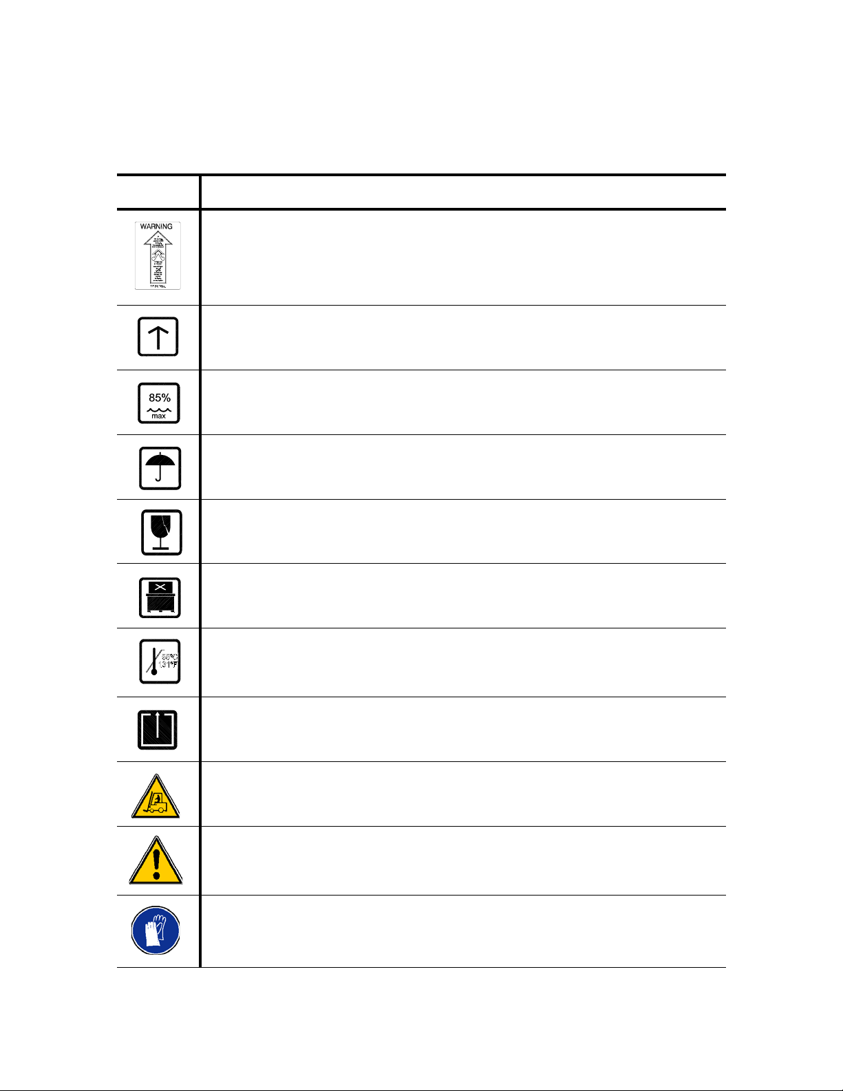
The tables below contain symbols which may be on your Basil 3500 Cage and Bottle Washer components:
Table 1-1. Symbols on Crate
Symbol Definition
Tip Indicator.
"If TIP 'N TELL arrow point is blue, this package has been on its side or tipped over
in transit. Make note on the bill of lading and check for damage. Any claims for tipping will be based on this notation."
This Side Up.
Maximum Relative Humidity.
Keep Dry.
Fragile.
Do Not Stack.
Maximum Temperature.
Open This Side.
Equipment contained in this crate is very heavy. Use a lift truck to move. Uncrate on
a level floor, as near as possible to the final installation location.
Personal injury and/or equipment damage hazard.
Always use tools appropriated for the task to be performed.
1-2
122996-977 Uncrating/Installation Instructions Safety Precautions
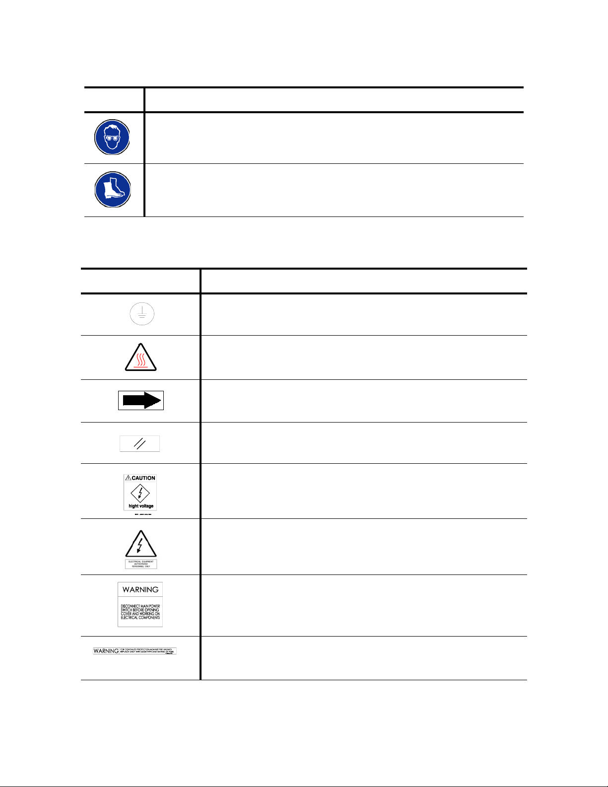
Table 1-1. Symbols on Crate (Cont’d)
Symbol Definition
Always use tools appropriated for the task to be performed.
Always use tools appropriated for the task to be performed.
Table 1-2. Definition of Symbols on Unit
Symbol Definition
Protective Earth (Ground).
Transfer of Heat, Hot Surface.
Rotation: Direction of Rotation Device.
Reset.
CAUTION. High Voltage.
ELECTRICAL EQUIPMENT.
Authorized Personnel Only.
WARNING.
Disconnect Main Power switch before opening cover and working on
electrical components.
WARNING.
For continued protection against fire hazard replace only with same
type and rating of fuse.
Safety Precautions Uncrating/Installation Instructions 122996-977
1-3

Table 1-2. Definition of Symbols on Unit (Cont’d)
Symbol Definition
DANGER.
Do not Operate Without Guards in Place.
WARNING! Chemical Burn Hazard:
Washer detergents are caustic...
Read and follow the precautions...
Wear protective gloves...
WARNING. Burn Hazard.
Surface May Be Hot
CAUTION
Always Cut OFF Electrical Supply Before Doing Any Repair.
Table 1-3. Definition of Symbols on Identification Nameplate
Symbol Definition
MODEL Model Number of The Unit.
S/N Serial Number of The Unit.
YEAR Year of Manufacture of The Unit.
kVA Kilovolt-Ampere.
V_~ Volt, Number of Phase (3 or 1[blank]), Alternate Current.
A Amperage.
Hz Hertz – Frequency of The Unit.
WIRE Number of Wires In The Electrical Cable (Ground Not Included).
PE Protective Ground Wire.
1-4
122996-977 Uncrating/Installation Instructions Safety Precautions

UNCRATING INSTRUCTIONS
IMPORTANT: A listing of the Safety Precautions to be observed when uncrating and installing this Cage
and Bottle Washer can be found in S
this information.
2.1 Open Crates NOTE: When opening crate, note the following:
WARNING – PERSONAL INJURY
AND/OR EQUIPMENT DAMAGE
HAZARD:
move unit.
WARNING – LACERATION
HAZARD:
tect your hands when removing bolts.
Use a forklift to
Wear gloves to pro-
ECTION 1. Do not install equipment until you have become familiar with
1) Use a forklift to move equipment.
2) Uncrate on level floor as close to installation site as possible.
IMPORTANT: Become familiar with components and installation
instructions before installing washer.
NOTE: Bring in and uncrate only one crate at a time.
1. Check tip indicator, located on upper left side of crate. Tip
Indicator contains a blue compound at bottom of indicator. If unit
has been tipped, residue from blue compound will be found
higher up in indicator. If unit has been tipped, notify STERIS. A
service technician will review equipment and determine if unit
was damaged.
2. Position unit to open crate from top. Provide a clear work area on
all sides.
3. Remove and discard wooden panels from top and sides of unit.
4. Remove and discard wooden frame from around unit.
2
5. Remove and discard polystyrene wrap from around unit.
6. For an assembled unit, go to S
REMOVE SKID.
ECTION 2.3, MOVE WASHER AND
Tip N-Tell
Indicator
2
1
Skid
Figure 2-1. Crate(s)
Uncrating Instructions Uncrating/Installation Instructions 122996-977
2-1

• Disassembled Unit:
NOTE: When uncrating unit, note the following:
WARNING – PERSONAL INJURY
AND/OR EQUIPMENT DAMAGE
HAZARD:
Use a forklift to move
unit.
WARNING – LACERATION
HAZARD: Wear gloves to protect your hands when removing bolts.
1) Bring in and uncrate only one crate at a time.
2) Major components in crates are numbered to assist in inventory
and assembly of unit. Review crate contents by matching numbers on components to numbers in parenthesis ( ).
3) Bolts, washers, nuts, and other items needed for the assembly of
unit are in a box labeled HARDWARE, inside Crate 2.
A fully equipped, disassembled unit should consist of two crates:
• Crate 1 contents:
- Frame and sump assembly (corners 1-4 and 2-3);
- Top assembly (20)
• Crate 2 contents:
- Two side panels: load side (6) unload side (7);
- Control panel (5);
- Control box (8);
- Two stainless piping and two brass piping (9, 10, 11, 12);
- Frame supports (21) [for 1, 2, 3, 4];
- Six guides (22) for oscillating spray header;
- Counterweights (23), two for single door units, four on double
door units;
- Door(s): load-side [for single door unit] (24), unload-side (25)
[or back panel for single-door unit];
- Service panels: service-side (26), nonservice-side (27);
- Side panels (1, 4 and 2, 3);
- Oscillating Spray header (28);
- Flexible hose (29);
- Two brackets (30) [for control box and side panels]
- Guides taped on hardware box;
- Envelope taped on hardware box containing:
Manuals, Warranty Card, and Pre-In-Service form. Ensure
appropriate person receives documentation.
- Hardware box (P117942-853):
Screws, bolts, washers, spring washers, wire connectors,
silicone tubes, sealant gun, etc.
- Insulating wool.
2-2
122996-977 Uncrating/Installation Instructions Uncrating Instructions

2.2 Disassembled Unit Assembly
NOTE: Before uncrating washer, take note of the following:
1) Uncrate washer as close as possible to installation site.
2) Refer to equipment drawing and seismic anchorage report, for
complete installation details.
1. Use a forklift to move top of unit from crate and set aside.
WARNING – PERSONAL
INJURY AND/OR EQUIPMENT
DAMAGE HAZARD: Use a
forklift to move unit.
Apply Silicone Here
2. Use a forklift to move frame assembly (bottom part of washer).
Remove four lag bolts securing washer base to skid. Install
frame assembly in place. Each corner is numbered 1, 2, 3, and 4
to ease frame support installation.
3. Using a spirit level, level frame assembly (end-to-end and sideto-side). If necessary, lift assembly and adjust four leveling legs
(one on each bottom corner of assembly). Lower assembly and
verify level.
4. Cut tie-wraps to remove floor grate from sump and set aside.
5. Install unit sides as follows (see Figure 2-2):
a. Install frame supports (1,4). Match support numbers with
those on frame assembly.
b. Apply a generous coat of silicone over sump walls, as shown
on Figure 2-2
c. Install left side panel. Secure left side panel to unit sump
using four 5/16-18 x 3/4 bolts,
6. Repeat Step 5 for right side wall. Use (2, 3) supports.
20
Apply Silicone Here
4
1/4-20 x 1/2" Flat
Head Screws
Apply Silicone Here
1/4-20 Bolts and Nuts
Apply Silicone Here
3
1/4-20 Bolts and Nuts
1/4-20 x 1/2" Flat Head Screws
2
1
Figure 2-2. Sides and Top Installation
Uncrating Instructions Uncrating/Installation Instructions 122996-977
2-3

IMPORTANT: Install oscillating spray header (28) into wash
chamber before installing door(s) and/or back panel.
7. Secure side walls to front and back of unit using sixteen 1/4-20 x
1/2 flat head screws, sixteen 1/4-20 bolts, and twelve 1/4-20 nuts
provided.
8. Install unit top (20) as follows (see F
IGURE 2-2).
NOTE: A forklift is required to install top.
a. Apply a generous coat of silicone on each side of top, before
bolting it.
b. Install top of unit, over sides. Secure with twenty-four 1/4-20
x 1/2" bolts and 1/4" flat washers provided.
9. Install oscillating spray header guides (22) inside wash chamber.
10. Install oscillating spray header (28).
11. Install unit door(s), chains, and counterweights (two for single
door unit, four for double door unit) as follows (see F
IGURE 2-3):
a. From top of unit, slide door(s) into position.
b. Remove tape securing chain over door slide edge.
c. Position chain over gear; then on mounting bracket, tighten
two bolts on gear to secure gear in place (see F
IGURE 2-3).
d. Repeat for each chain and gear.
e. Lift door and secure open using a 2 x 4" piece of wood.
f. Attach each chain to its counterweight, using chain link
provided.
g. Secure each counterweight sliding guide in position, using
eight 10-32 x 1/4" screws and 1/4" lockwashers provided.
h. Remove piece of wood and verify door for smooth operation.
12. Install piping (9-12). Match numbers on piping ends.
13. On exterior of unit, install load (6) and unload side panels (7).
14. Install control box (8) and control panel (5).
15. Connect flexible hose (29) from sump to oscillating spray
header.
16. Install service panels (26, 27) (and back panel, if option applies).
17. Go to S
2-4
122996-977 Uncrating/Installation Instructions Uncrating Instructions
ECTION 3, INSTALLATION INSTRUCTIONS.

10-32 x 1/4" Bolts
and 1/4"
Lockwashers
Bolt Chain Gear
Counterweight
Door
Figure 2-3. Install Chains and Counterweights
2.3 Move Washer and Remove Skid
TOP VIEW
• Assembled units:
NOTE: A fully equipped, assembled unit weighs approximately
2020 lb (916 kg).
1. With washer still mounted on skid, use a forklift to move washer
to installation site.
2. Open lower service access doors (see F
IGURE 2-4).
3. Verify tip indicator, located inside washer service compartment
(bottom left side). If unit has been tipped, notify STERIS.
4. Remove four lag bolts securing washer base to skid.
5. Remove and discard skid from under washer. If necessary, use
a piece of plywood as a small ramp to slide washer from skid to
floor. See F
IGURE 2-5.
6. Position washer in final location. Use tubing as rollers and roll
washer into position.
7. Go to S
ECTION 3, INSTALLATION INSTRUCTIONS.
Uncrating Instructions Uncrating/Installation Instructions 122996-977
2-5

and Viewing Window
Service Access
Door
Figure 2-4. Basil 3500 Cage and Bottle Washer
Control PanelVertical Sliding Door
2-6
122996-977 Uncrating/Installation Instructions Uncrating Instructions

TOP VIEW
Center of Gravity
FRONT VIEW
SIDE VIEW
Center of Gravity
Anchorage Point
Anchorage Point
Figure 2-5. Center of Gravity
Uncrating Instructions Uncrating/Installation Instructions 122996-977
2-7

2.4 Prepare Washer for Installation
1. Remove all tape from washer.
2. Locate electrical box compartment keys (taped inside Main Control Panel). Give keys to department supervisor.
3. Operator Manual, Warranty Card, and pre-in-service form are
enclosed in an envelope inside wash chamber. Ensure appropriate person receives documentation.
4. Before opening door(s), remove 1/4 - 20 x 4" counterweight
retaining bolts (two on each door) to unlock counterweight (see
F
IGURE 2-6) and allow operation of door(s).
5. Discard all packing material removed during uncrating procedures.
Counterweight Retaining Bolts
(1/4-20 x 4")
Counterweight
TOP VIEW
DOOR
Figure 2-6. Remove Counterweight Retaining Bolts
2-8
122996-977 Uncrating/Installation Instructions Uncrating Instructions

INSTALLATION INSTRUCTIONS
IMPORTANT: A listing of the Safety Precautions to be observed when uncrating and installing this Cage
and Bottle Washer can be found in S
this information.
ECTION 1. Do not install equipment until you have become familiar with
3
3.1 Technical
Specifications
3.1.1 Voltage, Amperage and Power Consumption
These specifications are intended to describe technical information given on nameplate of your washer and to state other relevant information.
Basil® 3500 Cage and Bottle Washer operates on:
• Steam-Heated units:
208 V, 60 Hz, 3-phase;
480 V, 60 Hz, 3-phase.
• Electric-Heated units:
480 V, 60 Hz, 3-phase.
A protective ground is required (Class 1 Equipment).
Maximum currents and power consumptions are indicated on nameplate.
Main supply voltage not exceeding ± 10% of nominal voltage.
Installation category: Overvoltage category II.
Always follow local electrical installation codes.
3.1.2 Permissible
Environmental Conditions
3.1.3 Seismic Anchorage System
Installation Instructions Uncrating/Installation Instructions 122996-997
This equipment is designated to give optimal results under the following conditions:
• Indoor use only;
• Altitude of operation up to: 6,265 ft (2,000 m);
• Maximum relative humidity is 80% for temperatures up to: 88ºF
(31ºC) decreasing linearly to 50% relative humidity at 104ºF
(40ºC);
• Pollution degree 2.
A Seismic Anchorage System is available for high risk seismic
zones.
3-1

3.2 Installation Requirements
Review installation requirements:
1. Clearance space shown on equipment drawing is necessary for
easy installation, proper operation and maintenance of washer.
2. Refer to equipment drawing for barrier wall flange(s) installation.
3. Utility service lines:
• To allow service of unit without shutting off building supply
lines, shutoff valves (not provided by STERIS) should be
installed on steam and water lines to unit. Shutoff valves
must be capable of being locked in OFF position only.
• Disconnect switches (not provided by STERIS) should be
installed in electric supply lines near washer
(see F
IGURE
3-1).
Disconnect switches must be capable of being locked in
OFF position only.
• If this machine is installed next to other equipment, shutoff
valves and disconnect switches should be located so that
service can be shut off to one piece of equipment at a time.
• Utility service requirements are shown on equipment drawing. This machine requires either 208 volts, 60 Hz, 3-phase,
3-Wire; or 480 volts, 60 Hz, 3-phase, 3-wire.
• Check equipment drawing or nameplate for proper voltage
and amperage.
• A protective conductor terminal is required (Class 1 Equipment).
Shut Off Valves
4. Floor under unit is a noncombustible surface.
5. Wall behind unit (if applicable) is a noncombustible surface.
6. Always follow local electrical codes and safety-related work
practices for wiring. Wire gauge should be appropriate to rating
of disconnect switch.
DisconnectSwitch
Figure 3-1. Utility Service Connections
3-2
122996-997 Uncrating/Installation Instructions Installation Instructions

3.3 Installation 1. Place washer, as shown on equipment drawing, in correct
relation to building supply lines. If unit is not at installation site,
refer to S
ECTION 2, UNCRATING INSTRUCTIONS, for proper moving
instructions.
2. Verify washer is level:
• Place a spirit level inside washer chamber.
• Level washer, end-to-end and side-to-side, using leveling
legs located at base of washer.
3. Open lower access panels.
3.4 Connect Utilities 1. COLD WATER (Option) - Purge building cold-water supply line
to remove chips, scale, etc. Connect line to washer. Cold-water
line is required for cold water pre-wash option and drain
discharge cool down.
2. HOT WATER - Purge building hot-water supply line to remove
chips, scale, etc. Connect line to washer, at top of unit.
3. STEAM (Option) - Purge building steam supply line to remove
chips, scale, etc. Connect line to washer, at top of unit. Steam
line is required for wash chamber.
4. STEAM RETURN (Option)- Connect washer steam return line to
building steam condensate return piping.
5. WASTE - Connect washer drain line to building waste line.
6. VENTILATION (Option) - Connect washer ventilation to a dedicated building exhaust.
7. COMPRESSED AIR - Connect unit air connection to building air
supply line.
8. ELECTRIC - Connect washer to building electrical supply. Verify
tight electrical connections.
9. Open building supply valves and check for leaks. Correct if necessary.
Installation Instructions Uncrating/Installation Instructions 122996-997
3-3

3.5 Cleanup 1. Remove any adhesive found on panels and inside chamber with
CAUTION – POSSIBLE EQUIPMENT DAMAGE:
ing adhesives from stainless
steel, use a solvent specially
formulated for that purpose.
Rub in a back-and-forth
(in same direction as surface
grain). Solvent rubbed in a
circular motion or applied
with a wire brush or steel
wool on door and chamber
assemblies can be harmful to
stainless steel. do not use
solvents on painted surfaces.
When remov-
motion
a suitable solvent. Keep solvents away from all painted surfaces
or damage may result.
2. Inspect work area to ensure all materials used during installation
have been removed.
THIS COMPLETES THE INSTALLATION. Contact STERIS to
schedule a service technician to test your installation and show persons designated how to operate equipment. Refer to O
PERATOR
MANUAL (P122998-741).
3-4
122996-997 Uncrating/Installation Instructions Installation Instructions

INSTALLATION VERIFICATION
IMPORTANT: A listing of the Safety Precautions to be observed when uncrating and installing this Cage
and Bottle Washer can be found in S
this information.
4.1 General An equipment drawing, showing all utility and space requirements,
ECTION 1. Do not install equipment until you have become familiar with
was supplied with washer. Clearance space specified on equipment
drawing is necessary for ease of installation and to ensure proper
operation and maintenance of equipment. If documents are missing
or misplaced, contact STERIS giving serial, equipment, and model
numbers of the unit. Replacement copies will be sent to you
promptly.
4
4.2 Installation Checklist
After your washer has been installed by qualified service technicians, complete the following checklist to ensure installation is complete and correct. If you desire, contact STERIS and schedule a
technician to test installation and demonstrate proper equipment
operation.
❑ Lockable shut-off valves (not provided by STERIS), for mainte-
nance purposes, are installed in steam and water lines in compliance with local occupational health and safety regulations, as
well as electric and plumbing codes.
❑ Disconnect switch (not provided by STERIS), for maintenance
purposes and capable of being locked in OFF position only,
installed in electric supply line in same room as washer, and in
compliance with local occupational health and safety regulations, as well as electric and plumbing codes.
NOTE: If unit is installed next to other equipment, shutoff valves
and disconnect switches should be located so that service can be
shut off to one piece of equipment at a time.
❑ Washer is positioned, as shown on equipment drawing, with
required service clearance space and in relation to building supply lines.
❑ Washer is installed between two walls with a key-locked service
door so service side is not accessible to operators.
❑ Building steam line provides maximum dynamic steam pressure
and flow rate to washer as specified on equipment drawing.
❑ Drip leg with steam trap installed in steam supply line.
❑ Building hot water line supplies water to washer at pressure and
temperature specified on equipment drawing.
❑ If applicable, building cold water line supplies water to washer at
pressure specified on equipment drawing.
❑ If applicable, building steam line supplies steam to washer at
pressure specified on equipment drawing.
Installation Verification Uncrating/Installation Instructions 122996-977
4-1

❑ Electrical supply for washer is as specified on equipment draw-
ing.
❑ Condensate return (if applicable) is sized as specified on equip-
ment drawing.
❑ Vent connection (if applicable) is sized as specified on equip-
ment drawing.
❑ Recirculation pump pressure is within 25 to 60 psig. Pump
rotates in direction shown by arrow.
❑ Self-cleaning screen assembly functioning properly.
❑ Header drive system functioning properly.
❑ All piping is leak-free and cabinet joints are completely sealed,
no leaks. (Check by running machine for 1/2 hour.)
❑ Door safety switch(es) functioning properly.
IMPORTANT: After a few weeks of operation, inspect units for leaks.
Retighten all clamps and connections.
4-2
122996-977 Uncrating/Installation Instructions Installation Verification

OPERATIONAL TEST
IMPORTANT: A listing of the Safety Precautions to be observed when uncrating and installing this Cage
and Bottle Washer can be found in S
this information.
ECTION 1. Do not install equipment until you have become familiar with
5
WARNING – BURN HAZARD:
• When checking automatic
stop feature, wear appropriate Personal Protective
Equipment (PPE) and open
chamber door slowly. Hot
water/steam may be
sprayed through door
opening if door is opened
during a cycle.
• Except for an emergency,
do not open door when
cycle is in progress. In an
emergency, first stop cycle
by pressing STOP touch
pad and wait for water flow
to stop. Wear appropriate
Personal Protective equipment (PPE) whenever
reaching into chamber.
• Allow piping to cool before
inspecting piping and/or
cleaning supply line strainers or valves.
CAUTION – POSSIBLE EQUIPMENT DAMAGE: Once threephase power is connected,
check pump for correct rotation. Incorrect pump rotation
may result in pump damage
and improper cleaning action.
WARNING – SLIPPING HAZARD:
To prevent slips, keep floor
dry. Promptly clean up any
spills or condensation. If
spilled liquids are detergents
or other chemicals, follow
safety precautions and handling procedures set forth on
detergent or chemical label
and/or Material safety Data
Sheet (MSDS)
Test procedure included in this section should be performed by a
STERIS or STERIS-trained service technician prior to normal operation of equipment.
1. Open chamber door.
2. Verify wash chamber is empty and all packing material has been
removed.
3. Close door, ensure POWER OFF/STANDBY rocker switch is in
POWER position.
4. Press SELECT CYCLE touch pad, then press START touch
pad. Let cycle run approximately 15 seconds to clear piping system of any foreign matter.
5. Verify pump rotation. Pump should turn in direction shown by
arrow. If pump is rotating in wrong direction, disconnect main
power, reverse any two 3-phase wires and recheck shaft rotation.
6. Wear appropriate Personal Protective Equipment (PPE), verify
automatic stop feature.
a. Being careful of hot water escaping, open front (load-side)
chamber door. Automatic Stop should shut off all service to
chamber. Press ALARM REPLY touch pad to silence
buzzer.
b. If double-door unit, close door and press START. Open
back (unload-side) chamber door (if option applies).
Automatic Stop should shut off all service to chamber. Press
ALARM REPLY touch pad to silence buzzer.
7. Remove four bolts securing self-cleaning filter flange in position.
Remove filter cartridge and clean under water. Replace filter cartridge inside self-cleaning filter and secure flange with four bolts
removed previously.
8. Close door and press START touch pad to resume cycle.
Inspect piping assembly for leaks. If any leaks occur, press
STOP touch pad, tighten hose connections and press START
again.
9. Allow cycle to run to completion. Verify that display shows:
PLEASE OPEN DOOR
AND REMOVE LOAD
10. Open door and unload chamber.
WASHER IS NOW READY FOR NORMAL OPERATION.
Operational Test Uncrating/Installation Instructions 122996-977
5-1
 Loading...