


OPERATOR MANUAL
Basil® 1100
Feeder Bottle Filler
(2004-03-04) P122996-004


A WORD FROM STERIS CORPORATION
This manual contains important information on proper use and routine
maintenance of the Basil® 1100 Feeder Bottle Filler. All personnel involved
in the use and maintenance of this equipment must carefully review and
comply with the warnings, cautions, and instructions contained in this
manual. These instructions are important to protect the health and safety of
personnel operating the equipment and should be retained in a conveniently
accessible area for quick reference.
Complete instructions for uncrating and connecting utilities, as well as
equipment drawings, have been furnished. If missing, contact STERIS for
replacement copies, giving the unit serial and model numbers .
STERIS carries a complete line of accessories for use with this equipment. A
STERIS representative will gladly review these with you.
Advisory
Indications for Use
Service Information
A listing of the
servicing this equipment can be found in Section 1 of this manual. Do not
operate or service the equipment until you have become familiar with this
information.
Any alteration of this equipment not authorized or performed by STERIS which
could affect units operation, will void the warranty, could adversely affect
operation efficacy, could violate federal, state and local regulations and
jeopardize your insurance coverage.
The Basil 1100 Feeder Bottle Feeder is designed for efficient filling of feeder
bottles used in animal care laboratories. The acid proportioner unit is designed to mix liquid additives into an animal drinking water dispensed by
bottles. The proportioner system is provided with a pH analyzer and a strip
printer designed to monitor and record the pH of the water outlet.
A thorough preventive maintenance program is essential to safe and proper
unit operation. This manual contains maintenance schedules and procedures
which should be followed for satisfactory equipment performance.
You are encouraged to contact STERIS concerning extended service maintenance agreements to give your unit planned maintenance, assuring equipment performance according to factory specifications. A global network of
skilled service specialists can provide periodic inspections and adjustments
to assure low-cost peak performance. STERIS can provide information
regarding annual maintenance agreements.
Safety Precautions
to be observed when operating and
See inside back cover for contact information.
©2004, STERIS Corporation. All rights reserved. Printed in Canada
Table of Contents Operator Manual 122996-004
i

THIS PAGE INTENTIONALLY LEFT BLANK
ii
122996-004 Operator Manual Table of Contents

TABLE OF CONTENTS
Section Title Page
A WORD FROM STERIS CORPORATION ................................................... i
1 LISTING OF SAFETY PRECAUTIONS AND SYMBOLS ..................... 1-1
2 UNCRATING/INSTALLATION INSTRUCTIONS ................................. 2-1
2.1 Uncrating Instructions ................................................................................................. 2-1
2.1.1 Open Crate ........................................................................................................... 2-1
2.1.2 Move Unit and Remove Skid ................................................................................ 2-1
2.1.3 Prepare Unit for Installation .................................................................................. 2-1
2.2 Installation Instructions ................................................................................................ 2-3
2.2.1 Before Installing Equipment ................................................................................. 2-3
2.2.2 Technical Specifications ....................................................................................... 2-3
2.2.3 Install Anchorage System..................................................................................... 2-4
2.2.4 Connect Utilities ................................................................................................... 2-4
2.2.5 Cleanup ................................................................................................................ 2-4
2.3 Installation Checklist .................................................................................................... 2-5
3 COMPONENT IDENTIFICATION ....................................................... 3-1
3.1 Component Identification ............................................................................................. 3-1
3.2 Control Panel .............................................................................................................. 3-2
3.2.1 Base Units ............................................................................................................ 3-2
3.2.2 Acid Proportioner Units ....................................................................................... 3-3
3.2.3 pH Monitor ............................................................................................................ 3-3
3.2.4 pH Strip Printer ..................................................................................................... 3-3
3.3 Accessories ................................................................................................................. 3-4
3.3.1 Filler Header ......................................................................................................... 3-4
3.3.2 Bottle Baskets ..................................................................................................... 3-5
4 OPERATING INSTRUCTIONS ........................................................... 4-1
4.1 Before Operating Equipment ....................................................................................... 4-1
4.1.1 How to Set a Function........................................................................................... 4-1
4.1.2 How to Prime the Injection Pump ......................................................................... 4-1
4.1.3 How to Change Water type .................................................................................. 4-2
4.1.4 How to Set Purge Time ......................................................................................... 4-3
4.1.5 How to Select Filling Time .................................................................................... 4-3
4.1.6 How to Change Filling Time Settings .................................................................... 4-4
4.2 Bottle Filler Operation .................................................................................................. 4-4
4.2.1 Base Units ............................................................................................................ 4-4
4.2.2 Acid Proportioner Units ........................................................................................ 4-5
4.3 Standby Mode (Acid Proportioner Units)..................................................................... 4-5
Table of Contents Operator Manual 122996-004
iii

TABLE OF CONTENTS (Cont'd)
Section Title Page
5 ROUTINE MAINTENANCE ................................................................ 5-1
5.1 General ........................................................................................................................ 5-1
5.2 Preventive Maintenance .............................................................................................. 5-2
5.3 Cleaning ...................................................................................................................... 5-3
5.3.1 Daily Cleaning ...................................................................................................... 5-3
5.3.2 Weekly Cleaning ................................................................................................... 5-4
5.3.3 Monthly Cleaning .................................................................................................. 5-5
6 TROUBLESHOOTING ....................................................................... 6-1
7 ILLUSTRATED PARTS BREAKDOWN ............................................... 7-1
iv
122996-004 Operator Manual Table of Contents

LISTING OF SAFETY PRECAUTIONS AND
SYMBOLS
1
The following list of the
WARNINGS indicate the potential for danger to personnel, and CAUTIONS indicate the potential for damage to
equipment. These
Safety Precautions
Safety Precautions
are repeated, where applicable, throughout the manual.
must be observed when operating and servicing this equipment.
WARNING – PERSONAL INJURY AND/OR EQUIPMENT DAMAGE HAZARD:
Only fully qualified service personnel should assemble and/or make adjustments to this equipment. Assembly
or adjustments done by inexperienced, unqualified personnel could cause personal injury or result in costly
damage.
Regularly scheduled preventive maintenance, in addition to the faithful performance of the minor maintenance
described within this manual, is required for safe and reliable operation of this equipment. Contact STERIS to
schedule preventive maintenance.
When moving the unit, use a forklift.
WARNING – ELECTRIC SHOCK AND BURN HAZARD:
Disconnect all utilities to unit before servicing. Do not service the equipment unless all utilities have been properly
locked out. Always follow electrical safety-related work practice standards.
Disconnect main power switch before opening cover and working on electrical components.
For continued protection against fire hazard replace only with same type and rating of fuse.
WARNING - CHEMICAL BURN AND/OR EYE INJURY HAZARD:
When filling bottles, always wear gloves that are appropriately resistant to the chemicals being used.
Wear gloves and eye protection when using a descaling product. Avoid contact with eyes or skin. If spilled or
splashed, flush with plenty of water for 15 minutes. If swallowed, DO NOT induce vomiting. Administer an alkali
with plenty of water. Seek medical attention immediately.
Liquid descaler is corrosive and can cause adverse effects to exposed tissues. Do not get into eyes, on skin,
or attempt to swallow. Avoid breathing of mists.
• Read and follow the precautions and instructions on the descaler label and in the Material Safety Data Sheet
(MSDS) prior to use.
• Wear protective clothing, gloves, and face shield when using descaler. If descaler contacts skin or eyes,
immediately flush with running water for 15 minutes. Seek medical attention.
• Use adequate ventilation. In case of inhalation, remove to fresh air and call a physician.
WARNING – LACERATION HAZARD:
When removing bolts, wear gloves to protect your hands.
(See next page for additional Warnings and Cautions)
Listing of Safety Precautions and Symbols Operator Manual 122996-004
1-1

WARNING – HEALTH HAZARD:
Vapors from solvent can be harmful. Use with adequate ventilation. Follow directions on the container.
WARNING - SLIPPING HAZARD:
To prevent slips, keep floors dry. Promptly clean up any spills or condensation
CAUTION – POSSIBLE EQUIPMENT DAMAGE:
Use non-abrasive cleaners when cleaning unit. Follow directions on containers and rub in a back-and-forth
motion (in same direction as surface grain). Abrasive cleaners will damage stainless steel. Cleaners rubbed in
a circular motion or applied with a wire brush or steel wool can be harmful to stainless steel. Do not use these
cleaners on painted surfaces.
When removing adhesives from stainless steel, use a solvent specially formulated for that purpose. Rub in a
back-and-forth motion (in same direction as surface grain). Solvent rubbed in a circular motion or applied with
a wire brush or steel wool on assemblies can be harmful to stainless steel. Do not use solvents on painted
surfaces.
When choosing chemicals, to be added to the water, choose ones which have low viscosity and which have no
abrasives or particles that would tend to gum or clog the Acid Proportioner System.
1-2
122996-004 Operator Manual Listing of Safety Precautions and Symbols
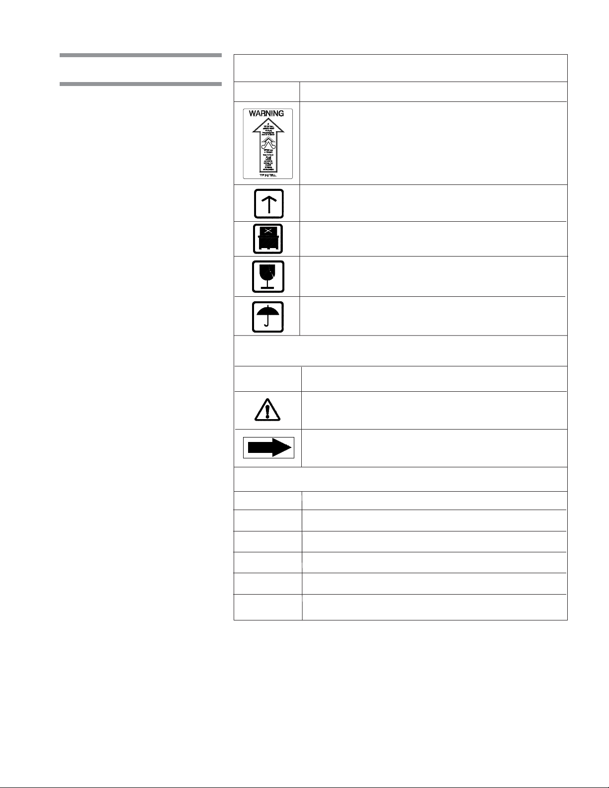
Symbols
Symbols on the Crate:
Symbol Definition
TIP'N TELL Indicator.
"If TIP'N TELL arrow point is blue, this package has
been on its side or tipped over in transit. Make note on
bill of ladding and check for damage. Any claims for
tipping will be based on this notation."
This Side Up.
Do Not Stack.
Fragile.
Keep Dry.
Symbols on the Unit:
Symbol Definition
Warning. Refer to Manual for Further
Information.
Rotation: Direction of the Rotating Device.
Information on the Nameplate:
MOD. Model of the Unit.
SER. Serial Number of the Unit.
kV Power Rating of the Unit.
V Volts.
A Amperage Rating of the Unit.
PH/Hz Phase/Hertz – Frequency of the Unit.
Listing of Safety Precautions and Symbols Operator Manual 122996-004
1-3

THIS PAGE INTENTIONALLY LEFT BLANK
1-4
122996-004 Operator Manual Listing of Safety Precautions and Symbols

UNCRATING/INSTALLATION INSTRUCTIONS
A room layout, floor plan, and equipment drawing, showing all utility and space
2.1 Uncrating Instructions
requirements, were shipped with the unit. The clearance space, specified on
the floor plan, is necessary for proper installation, operation, and maintenance
of the unit. If any of these documents are missing or misplaced, contact
STERIS, giving the unit serial number and model numbers. Replacement
copies will be sent to you promptly.
2
2.1.1 Open Crate
WARNING – LACERATION
HAZARD: When removing
bolts, wear gloves to protect your hands.
2.1.2 Move Unit and Remove Skid
NOTE: When uncrating unit, note the following:
1) Uncrate on a level floor, as close to installing site as possible. Use a forklift
to move crate.
2) Crate dimensions are: 100 x 41 x 79" (2540 x 1041 x 2006 mm).
3) Crate maximum weight is 1100 lbs (499 kg).
1. Verify Tip’N Tell indicator located outside crate (see Figure 2-1). Tip
indicator contains a blue compound at the bottom of the indicator. If unit has
been tipped, residue from the blue compound will be found higher up in the
indicator. If unit has been tipped, notify STERIS to arrange to have a service
technician review the equipment and determine if unit was damaged.
2. Assure crate is positioned so it can be opened from the top. Provide a clear
work area on all sides.
3. Carefully cut and remove bands from crate. Discard bands before continuing.
4. Using a nail puller, remove and discard top wooden panel.
5. Remove and discard side wooden panels.
6. Remove and discard polystyrene wrap from around unit.
1. With the unit still mounted on the skid, position forklift under unit frame and
move unit to installation site.
WARNING – PERSONAL
INJURY AND/OR EQUIPMENT DAMAGE HAZARD:
When moving the unit, use
a forklift.
2.1.3 Prepare Unit for Installation
Uncrating/Installation Instructions Operator Manual 122996-004
2. Unscrew and discard lag bolts holding unit to wooden shipping base.
3. Pull out and discard base.
1. Remove all tape and/or foam packing from Bottle Filler.
2. Remove tape securing drain cap to sump.
3. Slide Filler Header Manifold (accessory) into connection.
2-1
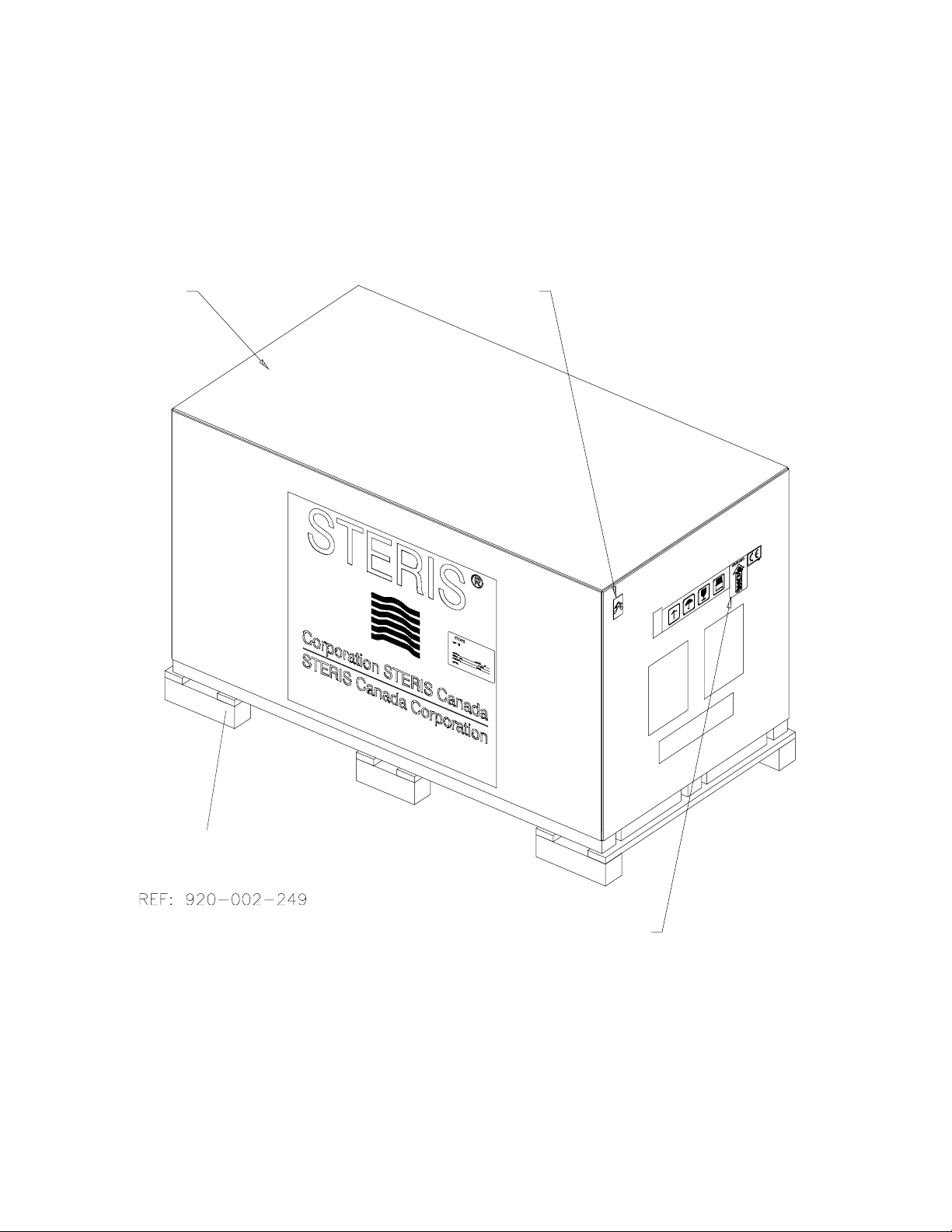
Top
Tip'N Tell
Skid
Tip Indicator
Figure 2-1. Crate
2-2
122996-004 Operator Manual Uncrating/Installation Instructions
2.2 Installation Instructions
2.2.1 Before Installing Equipment
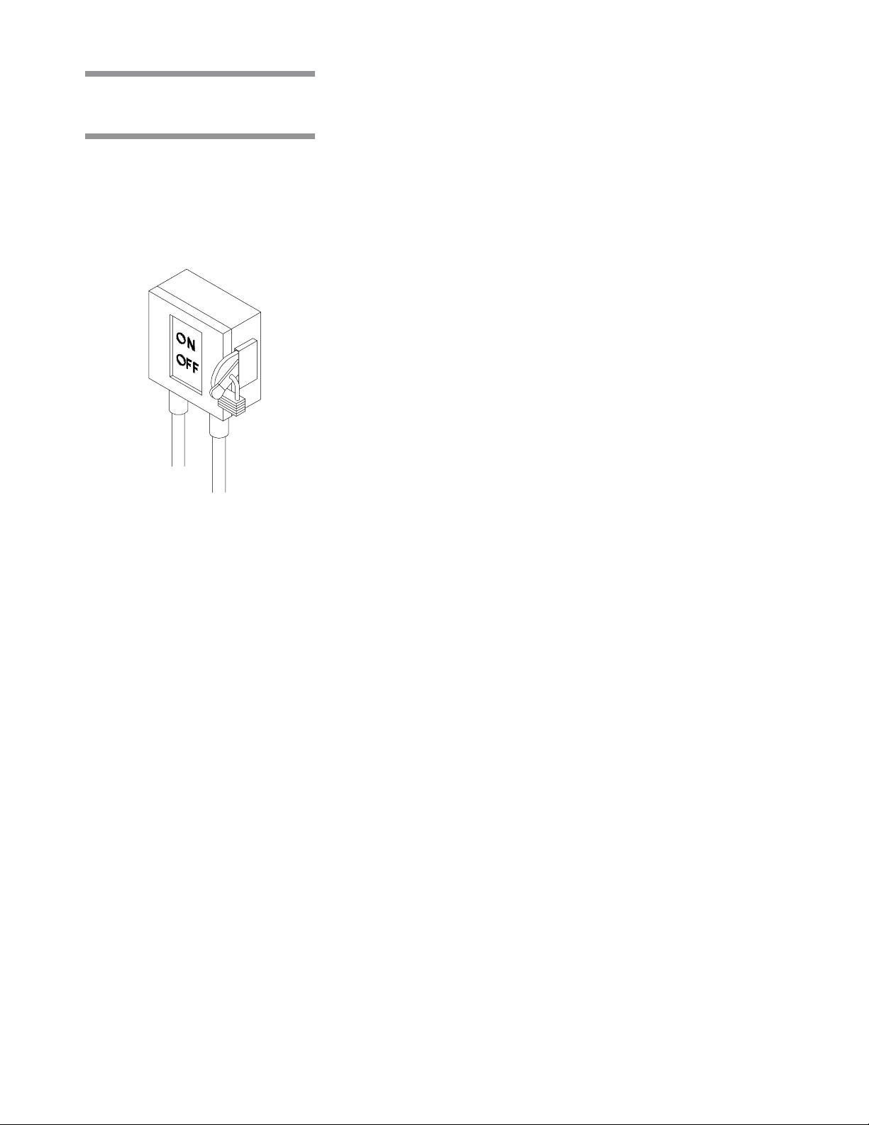
Figure 2-2. Disconnect
Switch
1. Review the installation requirements:
a. Clearance - The clearance space shown on the equipment drawing
indicates the space necessary for easy installation and proper operation
and maintenance of the Basil
b. Utility service lines:
• Disconnect switch (not by STERIS) must be installed in the electric
supply line near the bottle filler (see Figure 2-2). Disconnect switch
must be capable of being locked in the OFF position only.
• If this machine is installed next to other equipment, disconnect switch
should be located so that service can be shut off to one piece of
equipment at a time.
• Utility service requirements are as shown on the equipment drawing.
Verify the equipment drawing or identification plate (located over
electrical box cover) for proper voltage.
2. Assure the unit is placed, as shown on equipment drawing, in correct
relation to building supply lines.
®
1100 Bottle Filler.
NOTE: If unit is not at the installation site, refer to Uncrating Instructions (see
Section 2.1.2) for proper moving instructions.
3. Verify that the bottle filler is level.
a. Place a spirit level end-to-end and side-to-side on top of filling area.
b. If necessary, level the unit end-to-end and side-to-side, by adjusting the
leveling legs.
2.2.2 Technical Specifications
4. Unit is installed on Non-slip floor surface.
These specifications are intended to describe the technical information given
on the nameplate of your unit and to state other relevant information. Verify
Equipment Drawing or nameplate, for proper voltage and amperage.
• Voltage, Amperage, and Power Consumption
The Basil 1000 Bottle Filler
• 120 V~, 60 Hz, 1-phase, 2-wire
• Maximum current and power consumptions are:
• 120 V~, 10A, 1.2 kW
• Permissible Environmental Conditions
This equipment is designed to give optimal results in an indoor environment
where temperature is maintained between 41-104°F (5-40°C) and where
maximum relative humidity is 80% for temperatures up to 88°F (31°C),
decreasing linearly to 50% relative humidity at 104°F (40°C).
• Seismic Anchorage System
A Seismic Tie Down System is available for high risk seismic zones.
operates on:
2-3
Uncrating/Installation Instructions Operator Manual 122996-004

2.2.3 Install Anchorage System
Once unit is level, install anchorage system as follows:
1. Mark floor holes position. (If anchoring brackets do not touch the floor, use
shims.)
2. Using a forklift, move the unit to clear area.
3. Drill holes in floor.
4. Using a forklift, bring unit back into position.
5. Bolt brackets into position using bolts provided.
2.2.4 Connect Utilities
2.2.5 Cleanup
WARNING – HEALTH HAZARD: Vapors from solvent
can be harmful. Use with
adequate ventilation. Follow directions on the container.
CAUTION – POSSIBLE
EQUIPMENT DAMAGE:
When removing adhesives
from stainless steel, use a
solvent specially formulated for that purpose. Rub
in a back-and-forth motion
(in same direction as surface grain). Solvent rubbed
in a circular motion or applied with a wire brush or
steel wool on assemblies
can be harmful to stainless
steel. Do not use solvents
on painted surfaces.
1. DRAIN - Connect building waste line to unit drain line.
2. COLD WATER - Connect cold water supply line from building to unit as
described in the Equipment Drawing.
3. ELECTRICITY - Connect building electrical supply line to unit electrical
supply box as described in the Equipment Drawing.
1. Remove any adhesive found on panels with a small amount of nonflammable cleaning solvent. Keep solvents away from all painted surfaces or
damage may result.
2 Remove all protective paper from the unit cabinet panels. Slowly peel paper
away from stainless steel to reduce the level of static discharge.
3. Inspect filler head and filling area to assure all materials used during
installation have been removed.
THIS COMPLETES THE INSTALLATION.
confirm that all items on installation checklist have been satisfactorily implemented and operational test is conducted by a qualified service technician.
Follow procedure described in Section 4.2,
operation.
Before operating equipment,
Bottle Filler Operation
, to test unit
2-4
122996-004 Operator Manual Uncrating/Installation Instructions

2.3 Installation Checklist
After installing the unit, complete the following checklist to assure complete
and correct installation. Contact STERIS to schedule a demonstration of proper
equipment operation.
Shutoff valve (not provided by STERIS), for maintenance purposes, is
installed on the water line and is in compliance with local codes.
Disconnect switch, capable of being locked in OFF position only, is installed
on electrical supply line near the unit and in compliance with local codes.
NOTE: If unit is installed next to other equipment, shutoff valve and disconnect
switch should be located so that service can be shut off to one piece of
equipment at a time.
Feeder Bottle Filler is positioned, as shown on floor plan, with required
clearance space and in relation to building water supply line.
Feeder Bottle Filler is level. If necessary, use adjustable feet and/or add
shims (not included) to level unit.
Building waste line is connected to unit as specified on equipment drawing.
Non-slip floor surface (not provided by STERIS) around unit.
2-5
Uncrating/Installation Instructions Operator Manual 122996-004

THIS PAGE INTENTIONALLY LEFT BLANK
2-6
122996-004 Operator Manual Uncrating/Installation Instructions

COMPONENT IDENTIFICATION
Become familiar with all component and control locations and functions before
3.1 Component
Identification
Filler Header Manifold
With Spraying Jets
operating the Basil® 1100 Feeder Bottle Filler (see Figures 3-1 and 3-2).
Strainer
3
Control Panel
Curtain
Solution Tank
Seismic Anchorage
Filling Area
Drain
Sump Tank
Adjustable Foot
Recirculation Pump
Figure 3-1. Basil 1100 Feeder Bottle Filler - Base Unit
Control Panel
Filler Header Manifold
With Spraying Jets
Curtain
Stationary Gate
Solution Tank
Seismic Anchorage
Filling Area
Adjustable Foot
Sump Tank
Recirculation Pump
Strainer
Drain
Acid Pump
Stationary Gate
Figure 3-2. Basil 1100 Feeder Bottle Filler - Acid Proportioner Unit
3-1
Component Identification Operator Manual 122996-004

3.2 Control Panel
3.2.1 Base Units
Electrical control panel on base units is composed of the following (see
Figure 3-3):
• Main Power ON/OFF selector switch;
• START-MAN Pushbutton - For Manual Operation, press and hold green
lighted START-MAN pushbutton to obtain desired filling level for bottles;
• START-AUTO Pushbutton - For Automatic Operation, press blue lighted
pushbutton to activate timer;
• Timer - Set desired filling time to automatically fill the bottles.
Main Power ON/OFF
Selector Switch
START-AUTO Pushbutton
START-MAN Pushbutton
Timer
(Blue)
(Green)
Figure 3-3. Control Panel - Base Units
3-2
122996-004 Operator Manual Component Identification

3.2.2 Acid Proportioner Units
NOTE: For further information regarding the acid proportioner, please refer to
manufacturer’s instructions (provided).
Control panel on Acid proportioner units is composed of the following (see
Figure 3-4):
• STOP button - To stop unit operation. When released by twisting, STOP
button will cause the display to show STANDBY and unit will be ready to start
again;
• Alphanumeric Display - To monitor the unit’s operations;
• FUNCTION/SELECT button - To select a function or a function value;
• SET/SAVE button - To set a function value and/or save it;
• FILL/PURGE button - To select fill or purge cycle;
• SILENCE button - To silence the alarm buzzer.
3.2.3 pH Monitor
3.2.4 pH Strip Printer
Alphanumeric Display
SET/SAVE Button
SILENCE Button
pH Monitor analyzes the pH of all solutions before being dispensed to the
bottles. Monitor includes a display from which the operator can take the pH
readings.
NOTE: The pH Monitor touch pads are for use only by a trained technician, to
perform service procedures such as calibration, etc.
pH Strip Printer provides a printed record of solution pH levels being dispensed to the bottles. The printer uses pressure-sensitive paper (see Section 7,
Illustrated Parts Breakdown
, for reordering information), which may be
rewound on the roller as it is used, or torn off in sections and maintained.
Acid Proportioner
FILL/PURGE Button
pH Strip Printer
FUNCTION/SELECT
Button
STOP Button
pH Monitor
Label: "PUSH TO STOP.
TWIST TO RELEASE"
Figure 3-4. Acid Proportioner, pH Monitor, and pH Strip Printer
3-3
Component Identification Operator Manual 122996-004

3.3 Accessories
Stainless-steel manifold headers can accommodate different bottle/basket
sizes. Each manifold has individual stainless-steel jets for each bottle. It
connects to Bottle Filler by a quick-disconnect clamp.
3.3.1 Filler Header
• 5 x 5 Filler Header (Figure 3-5):
Dimensions: 14-3/4 x 16-3/4 x 2-3/4" (370 x 430 x 70 mm)
Coverage: 25 bottles
Figure 3-5. 5 x 5 Filler Header
• 4 x 6 Filler Header (Figure 3-6):
Dimensions: 11-1/2 x 20-1/2 x 2-3/4" (290 x 520 x 70 mm)
Coverage: 24 bottles
Figure 3-6. 4 x 6 Filler Header
3-4
122996-004 Operator Manual Component Identification

3.3.2 Bottle Baskets
Stainless-steel bottle baskets can accommodate different bottle sizes. Refer
to Figures 3-7 Through 3-10.
Figure 3-7. 5 x 5 Bottle Basket
(16 oz bottles [454 mL])
Figure 3-8. 5 x 5 Bottle Basket
(8 oz bottles [227 mL])
Figure 3-9. 4 x 6 Bottle Basket
(16 oz bottles [454 mL])
Component Identification Operator Manual 122996-004
Figure 3-10. 4 x 6 Bottle Basket
(8 oz bottles [227 mL])
3-5

THIS PAGE INTENTIONALLY LEFT BLANK
3-6
122996-004 Operator Manual Component Identification

OPERATING INSTRUCTIONS
NOTE: Refer to Section 3 for component location.
4.1 Before Operating
Acid Proportioner
Unit
4
4.1.1 How to Set a Function
4.1.2 How to Prime the Injection Pump
1. Verify that unit shutoff valve (water) is open.
The FUNCTION/SELECT button permits the selection of the five different
functions: Priming, Water Type, Purge Time, Filling Time, and Time Settings.
To set a particular function:
1. Press the FUNCTION/SELECT button to tell the controller you would like to
set this function. The display will show the present value of the function
selected.
2. To change the selected value, press the FUNCTION/SELECT button until
the desired value appears on the display.
3. Then press the SET/SAVE button to tell the controller to save this choice.
Prime the injection pump as follows:
1. Display must show:
STANDBY
NOTE: If display does not show STANDBY, press Red STOP button and twist
to release.
2. Check to see if plain or treated water has been selected:
CAUTION– POSSIBLE
EQUIPMENT DAMAGE:
When choosing chemicals,
to be added to the water,
choose ones which have
low viscosity and which
have no abrasives or particles that would tend to
gum or clog the Acid
Proportioner System.
Operating Instructions Operator Manual 122996-004
• Press FUNCTION/SELECT button. Display shows:
WATER
• Press SET/SAVE. Display will show:
PLAIN
or
TREATED
• If display shows: TREATED, press SET/SAVE again. Display will return
to: STANDBY.
• If display shows: PLAIN, press FUNCTION/SELECT. Display will
change to TREATED. Press SET/SAVE. Display will show STANDBY.
4-1

WARNING – CHEMICAL
BURN AND/OR EYE INJURY
HAZARD: When filling
bottles, always wear gloves
that are appropriately resistant to the chemicals
being used.
3. To prime injection pump, fill solution tank with approximately one gallon of
water, or enough to cause the display to stop flashing CHEMICAL TANK
LOW.
4. Press SET/SAVE. Display shows:
PRIME?
5. Press SET/SAVE again. Display shows:
PRIMING
...and the injection pump will begin to pump.
6. Loosen the tube fitting at the injection valve and remove tube from fitting.
7. Insert tube into a container. This will make it easier for the pump to complete
priming.
NOTE: Since solution tank is near floor level, placing tank at the same level as
the pump or higher will speed priming greatly.
8. The injection pump is primed when all the air bubbles are out of the solution
tubing and water is coming out of tube, into the container.
9. Press FUNCTION/SET. The injection pump will stop and display will show
STANDBY.
10. Reconnect the tube at the injection valve. Proportioner is now ready.
4.1.3 How to Change Water Type
Display can show either READY or STANDBY.
1. Press FUNCTION/SELECT. Display shows:
WATER
2. Press SET/SAVE. Display will show:
TREATED
or
PLAIN
3. Press FUNCTION/SELECT to select other water type.
4. Press SET/SAVE. There will be three rapid beeps, and display shows:
STANDBY
5. The unit will now dispense type of water selected.
NOTE: Anytime the proportioner is changed from plain to treated water or vice
versa, the proportioner will go into Standby mode. A Purge cycle must be
performed before filling a rack of bottles. The Purge cycle purges the mixing
chamber, piping, and manifold of the previously chosen type of water.
4-2
122996-004 Operator Manual Operating Instructions

4.1.4 How to Set Purge Time
NOTE: Purge is used for two different purposes:
1) To purge piping and manifold of all the previously selected water type
before filling the next rack of bottles with the new type of water selected.
2) To assure uniform bottle filling after unit has been sitting idle for more than
five minutes since the previous fill cycle.
1. Display shows:
READY
or
STANDBY
2. Press FUNCTION/SELECT until display shows:
PURGE TIME
3. Press SET/SAVE. Current purge time is displayed. Tenths of seconds are
flashing.
4. Press FUNCTION/SELECT until the desired tenths of seconds is displayed.
5. Press SET/SAVE. Seconds are flashing.
6. Press FUNCTION/SELECT until desired seconds is displayed.
7. Press SET/SAVE. Minutes are flashing.
4.1.5 How to Select Filling Time
8. Press FUNCTION/SELECT until desired minutes value is displayed.
9. Press SET/SAVE. The controller will emit three rapid beeps and display will
go to READY or STANDBY.
Two different preset filling times can be adjusted so that two different size
bottles can be filled during separate cycles. The two filling times are identified
as "A Time" and "B Time". To select the filling time, proceed as follows:
1. When displays shows READY or STANDBY, press FUNCTION twice.
Display shows:
FILL TIME
2. Press SET/SAVE. Display shows:
A TIME
or ...
B TIME
3. Press FUNCTION to select desired time.
4. Press SET/SAVE to confirm the selection. There will be three rapid beeps
and display goes back to READY or STANDBY.
4-3
Operating Instructions Operator Manual 122996-004

4.1.6 How to Change Filling Time Settings
To change the filling time length A or B, proceed as follows:
1. When displays shows READY or STANDBY, press FUNCTION until
display shows desired time:
A TIME
or..
B TIME
2. Press SET/SAVE once. Display will show the present time in minutes,
seconds and tenths of seconds:
0:00:0
__ Indicates flashing position.
3. To change value of the flashing digit, press FUNCTION/SELECT until
desired value is displayed.
4. Press SET/SAVE. Next digit flashes. Follow same procedure to set all four
time digits.
5. Press the SET/SAVE button to save time selection. Then, the controller will
beep three times and display will shown READY or STANDBY.
4.2 Bottle Filler Operation
4.2.1 Base Units
6. Once unit is in READY mode, retest fill time with a bottle rack in the fill area.
7. Repeat Steps 1 trough 6 to set B TIME.
1. Assure that ON/OFF selector switch is positioned to ON.
2. Set timer for desired fill time, depending on size of bottles. A few trials with
a basket in filling area may be necessary to determine appropriate fill time.
3. When ready, push a basket under filling head.
4. Press blue pushbutton once to fill bottles.
5. When bottles are filled, release basket from basket stopper and push basket
out of filling area.
6. At the end of shift, position ON/OFF selector switch to OFF.
7. Clean as described in Section 5,
Routine Maintenance
.
4-4
122996-004 Operator Manual Operating Instructions

4.2.2 Acid Proportioner Units
WARNING – CHEMICAL
BURN AND/OR EYE INJURY
HAZARD: When filling
bottles, always wear gloves
that are appropriately resistant to the chemicals
being used.
4.3 Standby Mode
(Acid Proportioner
Units)
1. If display shows STANDBY, press FILL/PURGE. Assure bottle fill area is
empty.
2. Press FILL/PURGE. System will purge for the purge time set (default is 25
seconds).
3. When display shows READY, position a rack full of bottles in the fill area.
4. Press FILL/PURGE. Display counts down the time programmed (default
time is 5 seconds for A TIME and 10 seconds for B TIME).
NOTE: When filling the bottles, note the following:
1) Fill times may vary somewhat, depending on the size of the bottles.
2) If time is set to zero and an attempt is made to purge or fill, display will show
NO TIME, then time must be set (refer to Section 4.1.6, How to Change Filling
Time Settings).
3) Operation of the unit may be stopped at any time by pressing STOP. Display
will go blank. Twist STOP button to release it and return proportioner to Standby
mode.
After a rack of bottles is filled, an internal timer begins counting down for five
minutes. If another fill cycle is run, the timer resets to five minutes and begins
counting down again. If the timer counts down five minutes without beginning
another fill cycle, then proportioner will switch into Standby mode. Display will
show: STANDBY, and pump will shut off.
NOTE: Pump runs continuously while proportioner is in ready mode.
Clean unit as described in Section 5,
Routine Maintenance
.
4-5
Operating Instructions Operator Manual 122996-004

THIS PAGE INTENTIONALLY LEFT BLANK
4-6
122996-004 Operator Manual Operating Instructions

ROUTINE MAINTENANCE
Procedures described in this section should be performed at regular intervals
5.1 General
WARNING – PERSONAL
INJURY AND/OR EQUIPMENT DAMAGE HAZARD:
• Regularly scheduled preventive maintenace, in addition to the faithful performance of the minor maintenance described within this
manual is required for safe
and reliable operation of
this equipment. Contact
STERIS to schedule preventive maintenance.
• Only fully qualified service
personnel should assemble and/or make adjustments to this equipment.
Assembly or adjustments
done by inexperienced,
unqualified personnel
could cause personal injury or result in costly damage.
as indicated. Local conditions (water quality, usage, etc.) may require more
frequent maintenance than indicated. The interval frequency should be
increased with increased usage of the equipment. Customer should maintain
a record of all maintanace procedures performed on the unit.
Should a problem occur, refer to Section 6,
tion 7,
Illustrated Parts Breakdown
A preventive maintenance agreement is available to assure peak equipment
performance and avoid unscheduled downtime. The agreement includes
maintenance adjustments and replacement of worn parts by a qualified
technician on a scheduled basis. Contact STERIS for further details. Maintenance procedures should be performed only by a qualified technician. Service
charges may be incurred. Consult your warranty for details.
Never permit unqualified persons to service the Bottle Filler.
Troubleshooting
, for replacement parts list.
5
. Refer to Sec-
WARNING – SLIPPING
HAZARD: To prevent slips,
keep floors dry. Promptly
clean up any sills or condensation.
5-1
Routine Maintenance Operator Manual 122996-004

Table 5-1 is to be used as a preventive maintenance record and, along with
5.2 Preventive Maintenance
the instructions in this section, as a guide to performing preventive maintenance. Preventive maintenance is not covered under warranty.
Table 5-1. Preventive Maintenance
SERVICE PERFORMED Min. Frequency
1.0 PREPARATION FOR PREVENTIVE MAINTENANCE
1.1 Discuss equipment with operators. 6 x per year
1.2 Follow appropriate safety procedures: prepare unit for Preventive Maintenance. 6 x per year
2.0 PIPING COMPONENTS
2.1 Verify each hand valve operates easily; check valve packing for leaks; 6 x per year
rebuild or replace as needed.
2.2 Rebuild fill water solenoid valve, if equipped. 1 x per year
2.3 Inspect cold water strainer for debris; clean if needed. 6 x per year
2.4 Inspect drain strainer for debris; clean if needed. 6 x per year
2.5 Check for plugged headers and jets; clean if needed 6 x per year
2.6 Verify proper alignment of spray jets. 6 x per year
3.0 MECHANICAL SYSTEMS
3.1 Inspect rollers for wear. 6 x per year
4.0 FINAL CHECKOUT AND TEST
4.1 Clean dirt and lint from components. Check all wiring, terminals, and socket 6 x per year
connections for damage or fraying.
4.2 Verify that unit has proper labels (CAUTION, WARNING). 6 x per year
4.3 Run a one-minute Fill Cycle to verify proper operation. 6 x per year
4.4 Reinstall any panel or cover removed. Check area to assure removal of all 6 x per year
materials used during inspection.
4.5 Notify customer that Preventive Maintenance inspection is complete. 6x per year
5-2
122996-004 Operator Manual Routine Maintenance

5.3 Cleaning
WARNING – CHEMICAL
BURN AND/OR EYE INJURY
HAZARD: Wear gloves and
eye protection when using
a descaling product. Avoid
contact with eyes or skin. If
spilled or splashed, flush
with plenty of water for 15
minutes. If swallowed, DO
NOT induce vomiting. Administer an alkali with
plenty of water. Seek medical attention immediately.
STERIS recommends the use of the following cleaning products (see Section 7,
Illustrated Parts Breakdown
• AmscrubTM Multipurpose Cleaner - for routine cleaning and polishing
of unit.
• PRY® Stain Remover Cream, for stubborn stains.
• Stainles Steel Cleaner - for clenaing stainless-steel surfaces.
• Liquid Descale - for removing scale and other hard water deposits from
unit.
, for ordering information).
NOTE: Follow manufacturer’s recommendations for proper product use (concentrations, precautions to be taken, etc). Read the MSDS for safety information.
5.3.1 Daily Cleaning
• Filler Header Manifold:
At the end of each day, visually inspect each filler manifold jet by looking into
each jet opening or by observing the spray pattern of each jet during operation.
If a jet appears to be clugged or partially blocked:
1. Push wire (of smaller diameter than the jet orifice) through each jet that
appears to be plugged.
2. Remove jet from each corner and turn unit on.
3. Replace jets and test for additional blockage.
4. If blockage remains, repeat process until jets are clear.
• Rollers and Sump:
Before cleaning or servicing conveyor rollers or sump, it is necessary to
remove a few rollers:
1. Remove plastic spacers located on side of rollers (see Figure 7-3).
2. Pull roller assembly inward (towards yourself).
3. Place left hand on roller white collar to hold collar firmly in place.
4. Push roller forward, pulling opposite end of roller up and away from
conveyor and roller shaft.
5. Repeat Steps 1 trough 4 for each roller to be removed.
6. Clean rollers in hot water using a mild detergent.
7. Rinse under running water.
8. Dry each roller using a clean, dry, lint-free cloth.
9. Repeat for each roller.
10. Remove plug from drain to drain accumulated water from sump.
5-3
Routine Maintenance Operator Manual 122996-004

11. Using a damp cloth or sponge, apply cleaner on sump panels in a back
and-forth motion.
12. Thoroughly wipe off cleaner.
After cleaning conveyor rollers, it is necessary to reassemble rollers as follows:
1. Insert roller on roller shaft (pulling inward towards you).
2. Push roller assembly on conveyor shaft, white collar included.
3. Turn white collar until it locks in position over shaft.
4. Reinsert roller spacers.
5. Repeat Steps 1 trough 4 for each roller to be reinstalled.
5.3.2 Weekly Cleaning
CAUTION – POSSIBLE
EQUIPMENT DAMAGE:
Use non -abrasive cleaners
when cleaning unit. Follow
directions on containers
and rub in a back-and-forth
motion (in same direction
as surface grain). Abrasive
cleaners will damage stainless steel. Cleaners rubbed
in a circular motion or applied with a wire brush or
steel wool can be harmful
to stainless steel. DO not
use these cleaners on
painted surfaces.
1. Clean Filler Header manifold, sump and rollers as previously described.
2. Clean Basil
®
1100 Feeder Bottle Filler exterior using Amscrub for general
stains and Pry Stain Remover Cream for stubborn stains.
3. Using a damp cloth or sponge, apply cleaner in a back-and-forth motion, in
same direction as surface grain.
4. Thoroughly wipe off cleaner.
5. Polish surface with a clean, dry, lint-free cloth.
5-4
122996-004 Operator Manual Routine Maintenance

5.3.3 Monthly Cleaning Remove hard water deposits from conveyor sump as follows:
NOTE: Depending on hardness of water being used, it may be necessary to
WARNING – CHEMICAL
BURN AND/OR EYE INJURY
HAZARD:
• Wear gloves and eye protection when using a descaling product. Avoid contact with eyes or skin. If
spilled or splashed, flush
with plenty of water for 15
minutes. If swallowed, DO
NOT induce vomiting. Administer an alkali with
plenty of water. Seek medical attention immediately.
• Liquid descaler is corrosive
and can cause adverse effects to exposed tissues.
Do not get into eyes or skin
or attempt to swallow.
Avoid breathing of mists.
remove hard water deposits more often. Remove deposits from sump whenever deposits become visible.
1. Remove a few rollers as described in Section 5.3.1,
3. Pour a small amount of Liquid Descale on a damp cloth, and rub each
sump surface in a back and forth motion (same direction as surface grain)
to remove hard water deposits.
5. Thoroughly wipe off cleaner.
6. Remove plug from sump.
7. Rinse off cleaner with water (using a hose, for example).
8. Reinstall plug in drain hole.
9. Clean rollers as previously described and reinstall.
Daily Cleaning
.
• Read and follow the precautions and instructions
on the label and in the Material Safety Data Sheet
(MSDS) prior to use.
• Wear protective clothing,
gloves, and face shield
when using descaler. If
Descaler contacts skin or
eyes, immediately flush
with running water for 15
minutes. Seek medical attention.
• Use adequate ventilation.
In case of inhalation, remove to fresh air and call a
physician.
5-5
Routine Maintenance Operator Manual 122996-004

THIS PAGE INTENTIONALLY LEFT BLANK
5-6
122996-004 Operator Manual Routine Maintenance

TROUBLESHOOTING
6
WARNING – PERSONAL
INJURY AND/OR EQUIPMENT DAMAGE HAZARD:
Only fully qualified service
personnel should assemble and/or make adjustments to this equipment.
Assembly or adjustments
done by inexperienced,
unqualified personnel
could cause personal injury or result in costly damage.
WARNING – ELECTRIC
SHOCK AND/OR BURN
HAZARD: Disconnect all
utilities to equipment before servicing. Do not service the equipment unless
all utilities have been properly locked out. Always follow electrical safety-related
work practices and standards.
This section describes the types of Basil® 1100 Feeder Bottle Filler malfunctions likely to occur and indicates probable causes and corrective actions.
If you are unable to correct the problem with use of the Table 6-1, Troubleshooting Chart, or if a problem occurs that is not described on the chart, please call
STERIS. A factory-trained technician will promptly place your equipment in
proper working condition. Service charges may be incurred. Consult your
warranty for details.
NOTE: Never permit unqualified persons to perform service on the bottle filler.
• Disconnect main power
switch before opening
cover and working on electrical components.
• For continued protection
against fire hazard, replace
only with same type and
rating of fuse.
WARNING – SLIPPING
HAZARD: To prevent slips,
keep floors dry. Promptly
clean up any spills or condensation.
6-1
Troubleshooting Operator Manual 122996-004

Table 6-1. Troubleshooting Chart
PROBLEM TO CORRECT
1. No water flow when green button
(Base Units) or FILL/PURGE button (Acid Proportioner Units) is
pressed.
2. During purge or fill, display shows
NO TIME (Acid Proportioner
Units).
3. Display shows CHECK WATER
SUPPLY, none of the controls operate (Acid proportioner).
4. Display shows CHEMICAL TANK
LOW (unit with optional acid
Proportioner Units).
5. Display shows an error message
alternating with pH reading (unit
with optional pH analyzer).
Call STERIS*.
Time must be set to other value than zero. Set time as required.
Tank has not filled within 5 minutes. Verify water shutoff valve is open and
water is supplied at pressure specified on floor plan. After water is turned
on, push STOP then release it to restore normal operation. If condition
recurs, call STERIS*.
Silence alarm by pressing SILENCE. Check chemical supply. Replace
if necessary.
Call STERIS*.
* Service charges may be incurred. Consult your warranty for details.
6-2
122996-004 Operator Manual Troubleshooting

ILLUSTRATED PARTS BREAKDOWN
Significant assemblies and components of the Basil® 1100 Feeder Bottle Filler
are illustrated and identified in this section. The part number, the description,
and the quantity required for each usage are given. Each indentation in the
description represents the assembly level. The UNITS PER ASSEMBLY
column is specific for the given assembly or subassembly level.
Use only STERIS authorized parts on this equipment. Use of unauthorized
parts will void the warranty. To reorder replacement parts and/or supply
products, proceed as follows:
1. Determine the function and application of the part required. Select the
most appropriate illustration.
2. From the illustration, obtain the item number assigned to the desired
part. Refer to the accompanying tabular list (usually on the facing page)
for the part number and description of the part.
3. Include the part number and description of your equipment on your
order.
4. Include the model and serial numbers of your equipment in your order.
5. Send your order directly to the STERIS Sales and Service Center
serving your area.
7
Contact STERIS if you need parts that are not listed.
7-1
Illustrated Parts Breakdown Operator Manual 122996-004

Figure 7-1. Basil 1100 Feeder Bottle Filler - Acid Proportioner Unit Shown
7-2
122996-004 Operator Manual Illustrated Parts Breakdown

FIG. &
ITEM
NO.
7-1 BASIL 1100 Feeder Bottle Filler – Acid Proportioner Unit ..... X
1 PANEL, CONTROL .......................................................................... 1
2 117990 354 CURTAIN, 36" .................................................................................. 2
3 117950 631 VALVE, MANUAL BALL, S/S, 3/4F ................................................ 1
4 117951 157 STRAINER, S/S, 3/4" ...................................................................... 1
5 117994 288 STOPPER, BASKET ........................................................................ 1
6 GATE, STATIONARY (SEE FIGURE 7-2) ..................................... 2
7 117990 573 ANCHORAGE, SEISMIC ................................................................. 4
8 117940 260 LEG, ADJUSTABLE ......................................................................... 4
9 TANK, SOLUTION ........................................................................... 1
10 117942 590 PUMP, RECIRCULATION ............................................................... 1
11 TANK, SUMP.................................................................................... 1
12 117941 192 HEADER, 4 X 6, S/S ........................................................................ A/R
PART
NUMBER
117913 096 LED, RED, 120V #M22-LED230-R.............................................. 1
117913 080 LED, GREEN, 120V #M22-LED230-G ........................................ 1
117913 092 LED, BLUE, 120V #M22-LED230-B ............................................ 1
117913 079 HEAD, ILLUMINATED BUTTON GREEN #M22-DL-G............... 1
117913 094 HEAD, ILLUMINATED BUTTON BLUE #M22-DL-B .................. 1
117913 081 CONTACT BLOCK, N.O. ASS #M22-AK10 ................................ 1
117913 095 BUTTON, SEL 2 POS ILLIMUNATED#M22-WRLK-R ............... 1
117913 020 TIMER, MULTI-FUNCTION, NEMA4X B846-500 ....................... 1
117942 548 • PROBE, PH ................................................................................ 1
117912 292 PROPORTIONER, ACID/MON/RECORD BFP674 60HZ .......... 1
117942 595 • BUTTON, STOP ........................................................................ 1
117942 597 • SENSOR, WATER LEVEL ............................................................ 1
117942 599 • KIT, REPAIR .................................................................................. A/R
117942 600 • O-RING .......................................................................................... A/R
117942 598 • SENSOR, WATER LEVEL ............................................................ 1
117941 176 HEADER, 5 X 5, S/S ........................................................................ A/R
117941 092 • JET, SPRAYING, S/S .................................................................... A/R
DESCRIPTION
UNITS PER
ASSEMBLY
Illustrated Parts Breakdown Operator Manual 122996-004
7-3

Figure 7-2. Stationary Gate Assembly
7-4
122996-004 Operator Manual Illustrated Parts Breakdown

FIG. &
ITEM
NO.
PART
NUMBER
DESCRIPTION
7-2 STATIONARY GATE ASSEMBLY ...................................... X
1 117950 866 SCREW, S/S, TRUSS HEAD, 10-32 X 3/8" ................................... 3
2 117950 976 WASHER, S/S, 1/4" ......................................................................... 3
3 117984 710 GATE, STATIONARY ...................................................................... 1
4 117950 952 NUT, S/S, 1/4-20.............................................................................. 2
117950 899 BOLT, S/S, 1/4-20 X 1/2" (NOT SHOWN) ..................................... 2
5 117984 732 ANGLE, STATIONARY GATE ADJUSTABLE ............................... 1
UNITS PER
ASSEMBLY
Illustrated Parts Breakdown Operator Manual 122996-004
7-5

Figure 7-3. Roller Assemblies
7-6
122996-004 Operator Manual Illustrated Parts Breakdown

FIG. &
ITEM
NO.
PART
NUMBER
DESCRIPTION
7-3 ROLLER ASSEMBLIES ...................................................... X
1 117908 287 ROLLER, CPVC (HIGH TEMPERATURE)..................................... A/R
2 117907 005 CAP, ROLLER END (WITHOUT SHOULDER) .............................. A/R
117907 952 CAP, ROLLER END (WITH SHOULDER) ...................................... A/R
3 117984 416 COLLAR, HOLDING ........................................................................ A/R
4 117984 685 AXLE, LONG .................................................................................... A/R
5 117984 686 AXLE, SHORT.................................................................................. A/R
6 117984 684 COLLAR, HOLDING ........................................................................ A/R
UNITS PER
ASSEMBLY
Illustrated Parts Breakdown Operator Manual 122996-004
7-7

THIS PAGE INTENTIONALLY LEFT BLANK
7-8
122996-004 Operator Manual Illustrated Parts Breakdown

FIG. &
ITEM
NO.
PART
NUMBER
DESCRIPTION
Table 7-1. Miscellaneous Parts
1 117942 588 PUMP, INJECTION .......................................................................... 1
2 117942 592 CONTACTOR, MAGNETIC ............................................................. 1
3 117942 593 BLOCK, HEATER ELEMENT .......................................................... 1
4 117940 037 VALVE, SOLENOID, COPPER, 3/4" F ........................................... 1
117941 680 • KIT, REPAIR .................................................................................. A/R
117904 009 VALVE, SOLENOID, S/S, 3/4" F .................................................... 1
5 117942 596 VALVE, WATER INJECTION, PLASTIC, 1/2" ............................... 1
6 117942 594 CABLE, LOW LEVEL SOLUTION................................................... 1
7 117950 209 VALVE, SOLENOID, COPPER, 1"F, WATER ............................... 1
117950 212 • KIT, REPAIR .................................................................................. 1
8 117940 714 FUSE, 0,5 A ..................................................................................... 1
Table 7-2. Cleaning Products
UNITS PER
ASSEMBLY
NM400 Amscrub
TM
Multipurpose Cleaner ....................................................32 oz, 12 per case
1051-08 Liquid Descale Liquid Scale Remover ...........................................1 gal, 4 per case
NM430 Pry® Stain Remover Cream ............................................................ 12 oz, 12 per case
NM410 Stainless Steel Cleaner ...................................................................18 oz can, each
Illustrated Parts Breakdown Operator Manual 122996-004
7-9

THIS PAGE INTENTIONALLY LEFT BLANK
7-10
122996-004 Operator Manual Illustrated Parts Breakdown

Contact Information:
Sales and Service:
STERIS Corporation
5960 Heisley Road
Mentor, Ohio 44060
Tel.: 440 354 2600
Fax : 440 639 8199
Manufacturer:
Corporation STERIS Canada
490 boul. Armand-Paris
Beauport (Québec)
Canada G1C 8A3
Tel.: 418 664 1549
Fax: 418 664 0188
Technical Assistance:
STERIS Engineering Services
2424 West 23rd Street
Erie, PA 16506
Tel.: 814 452 3100
Fax: 814 870 8400
Authorized EU Representative:
STERIS Limited
STERIS House
Jays Close
Viables
Basingstoke
Hampshire RG22 4AX
United Kingdom
Tel.: 44 1256 840400
Fax: 44 1256 866502
Web Site: www.steris.com

 Loading...