


DC400

DC400/A
USER INSTRUCTION SUPPLEMENT
M/N DC400/A, P/N 101-00802
Doc. P/N: 61-101-00802.EF2
Revision G
January 7, 2015
_________________________________________
Adapter Module
MOD C, used with
DC400 OR DC400A
Corporate Headquarters
4101 Northwest 29th Street
Miami, Florida 33142
www.barfieldinc.com
Email: gsesales@barfieldinc.com
P/N’s 101-00800 or 101-00850
Digital DC Fuel Quantity Test Sets
For
BEECHCRAFT MODELS
1900/1900C, UA and UB
and
1900C/1900D, UC and UE
Barfield Inc. Confidential and Proprietary Information.
This document and all the information contained herein is the sole property of Barfield Inc.
No intellectual property rights are granted by the delivery of this document or the disclosure of its content.
This entire document is proprietary information and shall not be reproduced or disclosed to a third party without
the express written consent of Barfield Inc.
This document and its content shall not be used for any purpose other than that for which it is supplied.
Copyright © 2015 Barfield Inc. All Rights Reserved.

THIS PAGE INTENTIONALLY LEFT BLANK

APPLICABILITY
This manual is one of a family of manuals, each developed to address an individual
Adapter Module especially designed for the DC-400 / DC-400A Digital Fuel Quantity Test
Sets. It contains complete instructions for the maintenance, inspection, testing,
troubleshooting, and calibration of the Gull Airborne and Ragen Data Fuel Quantity
Systems.
These aircraft include (at the time of this writing):
1900 ............................... S/N UA
1900C ............................. S/N UB
1900C ............................. S/N UC
1900D ............................. S/N UE
61-101-00802.EF2 (REV. G) APP
January 7, 2015 Page iii

THIS PAGE INTENTIONALLY LEFT BLANK

REVISION RECORD
REV.
A
B
C
D
E
F
G
260-00678
260-00729
260-00779
260-01003
260-01076
ECO #
N/A
260-00617
REV. DATE
Mar/17/03
May/20/03
Sep/15/06
Jan/23/09
Apr / 29 / 10
Apr/29/14
Jan/07/15
First Issue. This supplement replaces
56-101-00802 manual and covers MOD B (or
earlier) releases of 101-00802.
For Mod C or later releases of adapter module.
Modifications to the company logo, company
contact information and listed part 101-00814
were implemented. Beech probe adapter cable
101-00829 is a reflection of the said changes to
adapter cable 101-00814.
Updated Company Logo
List of Approved Repair Facilities and
Recertification Information were added (page iv)
Revised per feedback from Beech and added
section 7. System Wiring Integrity Test.
Updated Barfield logos.
DESCRIPTION OF CHANGE
61-101-00802.EF2 (REV. G) REV
January 7, 2015 Page v

THIS PAGE INTENTIONALLY LEFT BLANK

r
LIST OF APPROVED REPAIR FACILITIES
The manufacturer of this equipment does not recommend the user to attempt any maintenance
or repair. In case of malfunction, contact the manufacturer, to obtain the list of approved repai
facilities worldwide, ensuring that this equipment will be serviced using proper procedures and
certified instruments. A Return Maintenance Authorization (RMA) number will be assigned
during this call, to keep track of the shipment and the service.
BARFIELD PRODUCT SUPPORT DIVISION
Telephone: (305) 894-5400 Shipping Address:
(800) 321-1039
Barfield, Inc.
Fax:
Miami, Florida 33142
Email:
Barfield, Inc.
P.O. Box 025367
Miami, FL 33102-5367
USA
(305) 894-5401 4101 NW 29th Street
gsesales@barfieldinc.com USA
Mailing Address:
Barfield Adapter Module, P/N 101-00802, has a one-year recertification requirement.
Qualified technicians in a shop equipped with the necessary tooling, facilities, and
Barfield-approved procedures must perform the maintenance required by this unit.
61-101-00802.EF2 (REV. G) LOARF
January 7, 2015 Page vii
RECERTIFICATION

THIS PAGE INTENTIONALLY LEFT BLANK

CONTACT INFORMATION
USERS ARE REQUESTED TO
NOTIFY THE MANUFACTURER OF
ANY DISCREPANCY, OMISSION OR
ERROR FOUND IN THIS SUPPLEMENT.
PLEASE SEND YOUR COMMENTS TO:
BARFIELD, INC.
ATTN: GSTE
4101 NORTHWEST 29TH STREET
MIAMI, FL 33142
USA
TELEPHONE (305) 894-5400
(800) 321-1039
FAX (305) 894-5401
EMAIL ADDRESS: gsesales@barfieldinc.com
61-101-00802.EF2 (REV. G) CONTACT INFO
January 7, 2015 Page ix

THIS PAGE INTENTIONALLY LEFT BLANK

TABLE OF CONTENTS
Applicability
Revision Record
List of Approved Repair Facilities / Recertification
Contact Information
Table of Contents
List of Tables
PAGE
1. Description ........................................................................................................ 1
2. Operation
1. System Insulation Test ................................................................................. 3
2. Insulation Test (Individual Probes) ............................................................... 8
3. System Capacitance Test ........................................................................... 12
4. Capacitance Test (Individual Probes) ......................................................... 15
5. Indicator Test ............................................................................................... 21
6. Preferred Calibration Test (with Dry Tanks) ................................................ 26
7. System Wiring Integrity Test ....................................................................... 29
3. Alternate Tests
1. Probes Bench Test ...................................................................................... 34
2. Indicator Bench Test ................................................................................... 37
3. Alternate Calibration (Wet Tanks) ............................................................... 41
61-101-00802.EF2 (REV. G) TOC
January 7, 2015 Page xi

THIS PAGE INTENTIONALLY LEFT BLANK

LIST OF TABLES
PAGE
1. Conductance to Megaohm Conversion ...................................................................... 6
2. Tank Capacitance Empty ........................................................................................... 14
3. Tank Capacitance Full ............................................................................................... 14
4. Probe Capacitance Empty (1900/1900C, UA and UB) .............................................. 18
5. Probe Capacitance Empty (1900C/1900D, UC and UE) ........................................... 18
6. Probe Capacitance Full (1900/1900C, UA and UB) .................................................. 19
7. Probe Capacitance Full (1900C/1900D, UC and UE) ............................................... 19
8. Add for Full .................................................................................................... 27
61-101-00802.EF2 (REV. G) LOT
January 7, 2015 Page xiii

THIS PAGE INTENTIONALLY LEFT BLANK

CHAPTER 1 DESCRIPTION
A. Capabilities
(1) Complete testing of fuel quantity system.
(2) Testing of individual fuel tanks.
(3) Testing of indicators.
(4) Dry and wet tank calibration.
B. Panel Controls
(1) See Instruction Manual 56-101-00850 for details on the DC400A Fuel
Quantity Test Set. See Technical Manual 57-101-00800 for information
on the DC400 Digital Fuel Quantity Test Set.
(2) Refer to Aircraft Maintenance Manual for description of the aircraft fuel
quantity system.
C. Aircraft System Description
(1) Refer to the Aircraft Maintenance Manual for specific procedures and
maintenance practices.
D. Equipment Required (or equivalent)
(1) DC400A Digital Fuel Quantity Test Set, P/N 101-00850 or the DC400
Digital Fuel Quantity Test Set, P/N 101-00800
(2) Barfield Instruction Manual 56-101-00850 (DC400A) or Barfield
Technical Manual 57-101-00800 (DC400)
(3) Fuel Quantity Adapter Module, P/N 101-00802
(4) Probe Adapter Cable, Barfield P/N 101-00829 or 101-00814
(5) Test leads, banana plug to alligator clip, P/N 101-01012
(6) 15-pin adapter cable, Barfield P/N 101-00831 or 101-00817
NOTE: Barfield adapter cables are available as a separate
purchase.
(7) A 1900/1900C/1900D Beech Probe adapter pin
(8) A 28 VDC Power Supply
(9) A Probe Selector Unit:
For 1900/1900C, UA and UB: P/N 114-389001/935
For 1900C/1900D (UC, UE): P/N 118-389004/935
61-101-00802.EF2 (REV. G) CH. 1
January 7, 2015 Page 1 of 44

E. Precautions
(1) Refer to Aircraft Maintenance manual for proper fueling and defueling
procedures. Observe all safety precautions.
(2) Refer to the Aircraft Maintenance manual for location of the system
components and instructions for removal and replacement.
(3) Insure fuel quantity circuit breakers are open and they remain open
while aircraft and test set connections are broken or made.
(4) Insure power remains OFF unless otherwise specified.
F. Preliminary
(1) To insure the integrity of all system components, perform the
Insulation, Capacitance tests first. Then, perform one of the Indicator
tests (System or Bench) and, if necessary, the Probe Bench test.
These tests will provide an effective means for troubleshooting the
system.
(2) After performing an indicator test and before returning the aircraft to
service, calibrate the aircraft fuel quantity system using the Preferred
(or Alternate) Calibration Test.
(3) Failure to calibrate the system could result in an inaccurate fuel
quantity indication.
G. Disclaimer
(1) BARFIELD, INC., neither a vendor nor supplier of fuel quantity systems
or an airframe manufacturer, has no control over calibration figures or
procedures. A variant between actual values and those recommended
may exist. However, the information presented is correct to the best of
our knowledge at time of publication and is presented for reference
only.
61-101-00802.EF2 (REV. G) CH. 1
January 7, 2015 Page 2 of 44

CHAPTER 2 OPERATION
1. SYSTEM INSULATION TEST
Note: Refer to PRECAUTIONS and PRELIMINARY sections (Chapter 1).
Note: This test may be performed with either wet or dry tanks.
A. Aircraft Preparation
(1) Disconnect the aircraft battery.
Caution: When lowering or raising pilot fuel panel, insure aircraft
battery is disconnected.
(2) Access the indicator.
(3) Open the circuit breakers.
Caution: When breaking or making indicator connections, insure that
the applicable circuit breaker(s) are open.
(4) Disconnect the aircraft wiring plug at the indicator.
B. Test Set Preparation
(1) Set the ON/OFF switch to OFF.
(2) Rotate the TEST FUNCTION switch to IND AMP.
(3) Set the INSULATION/SYSTEM switch to INSULATION.
(4) Rotate the INS TEST POINTS switch to LO-Z/GND.
(5) Set the AUX/MAIN switch to MAIN/TOT.
61-101-00802.EF2 (REV. G) CH. 2
January 7, 2015 Page 3 of 44
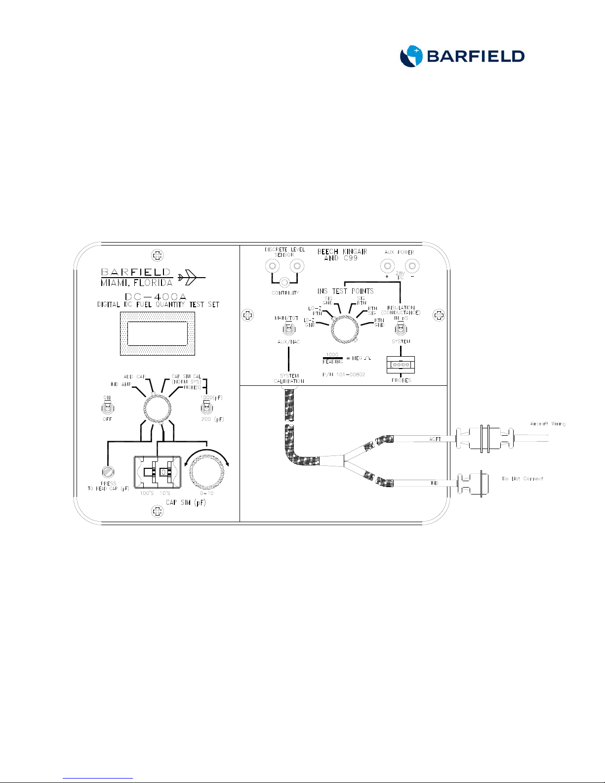
C. Connecting Test Set
(1) Set up the test set (T/S) as shown in Figures 1 and 2.
(2) Connect the test set ACFT connector to the aircraft wiring plug
removed from the indicator.
(3) Connect the test set ACFT connector to the ACFT connector of the
adapter cable.
(4) Do not connect the test set IND connector of the adapter cable.
(5) Do not connect the test set IND connector.
Figure 1 Insulation Test Connector Setup
61-101-00802.EF2 (REV. G) CH. 2
January 7, 2015 Page 4 of 44
 Loading...