

Bard WPV48D, WPV60D Installation Instructions Manual
WATER SOURCE
INSTALLATION
INSTRUCTIONS
HEAT PUMP
MODELS:
WPV48D
WPV60D
Ground Water Temperatures 45° - 75°
Earth Loop Fluid
Temperatures 25° - 110°
BARD MANUFACTURING COMPANY
Bryan, Ohio 43506
Since 1914...Moving ahead, just as planned.
MIS-658
Manual: 2100-250G
Supersedes: 2100-250F
File: Volume I, Tab 8
Date: 09-25-01
Copyright 2001

CONTENTS
Application and Location
General................................................................... 2
Shipping Damage ................................................... 2
Application .............................................................. 2
Location .................................................................. 2
Ductwork................................................................. 2
Filter........................................................................ 3
Condensate Drain................................................... 3
Piping Access to the Unit........................................ 3
Wiring
Main Power............................................................. 4
Thermostat Low Voltage Wiring ............................. 4
Accessories
Add-on DPM26A Pump Module Kit ........................ 6
General................................................................... 6
Installation .............................................................. 6
Closed Loop (Earth Coupled Ground
Loop Applications)
Circulation System Design ..................................... 7
Heat Pump Connections Without Pump Kit............ 9
Piping Connections................................................. 9
System Start Up Procedure .................................. 12
Open Loop (Well System Application)
Water Connections............................................... 13
Well Pump Sizing ................................................. 14
System Start Up Procedure .................................. 14
Water Corrosion ................................................... 15
Remedies of Water Problems............................... 16
Lake and Pond Installations ................................. 17
Sequence of Operation
Cooling With or Without Duct Heaters ................. 19
Single Stage Heat Without Duct Heaters ............. 19
Two Stage Heat With Duct Heaters...................... 19
Emergency Heat ................................................... 19
Pressure T ables .................................................25
Quick Reference Trouble-Shooting Chart .......26
Thermostat Diagrams........................................27
Wiring Diagrams ...........................................28-30
Ground Source Heat Pump
Performance Report ................................31-32
T ables
Table 1 Specifications ...................................... 1
Table 2 Water Coil Pressure Drop.................... 1
Table 3 Indoor Blower Performance ................. 1
Table 4 Accessory Items - Duct Heaters .......... 5
Table 5 Constant Low Valves ......................... 13
Table 6A and 6B Capacity
& Efficiency Ratings............. 23
Table 7 Capacity Multiplier Factors ................ 24
Table 8 Correction Factors ............................. 24
Table 9 Flow Rates for Various Fluids............ 24
Table 10 Pressure Table – Cooling .................. 25
Table 10A Pressure Table – Heating .................. 25
Figures
Figure 1 Filter Removal....................................... 3
Figure 2 Piping Access to the Unit...................... 3
Figure 3 Optional Terminal Board Cover............. 4
Figure 4 Duct Heater........................................... 5
Figure 5 Connection of Water Lines ................... 6
Figure 6 Components for Circulating System ..... 7
Figure 7 .............................................................. 9
Figure 8 .............................................................. 9
Figure 9 .............................................................. 9
Figure 10 Pump Module Hookup ........................ 10
Figure 11 ............................................................ 10
Figure 12 Pump Module Hookup Performance... 11
Figure 13 Pressure and Temperature Sensing
Adapter and Components................... 11
Figure 14 Water Connection Components .......... 14
Figure 15 Cleaning Water Coil............................ 16
Figure 16 Water Well System............................. 18
Figure 17 Functional Components...................... 20
Figure 18 Control Location.................................. 20
Figure 19 Water Source Heat Pump -
Cooling Cycle...................................... 21
Figure 20 Water Source Heat Pump -
Heating Cycle ..................................... 22
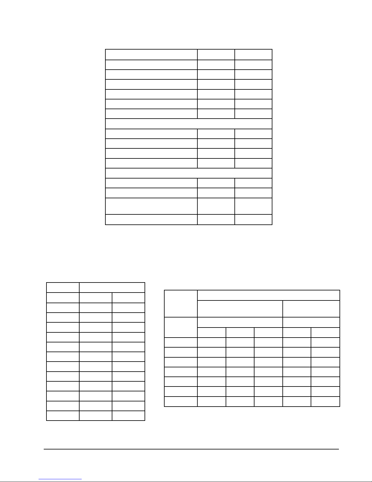
TABLE 1
SPECIFICATIONS
LEDOMD84VPWD06VPW
)HP/V/ZH06(gnitaRlacirtcelE1-802/0321-802/032
egnaRegatloVgnitarepO791-352791-352
yticapmAtiucriCmuminiM5.430.63
eziSeriWdleiF+8#8#
.rkB.tkCro.xaMesuFyaleD++0506
802/032spmAtinUlatoT0.72/7.328.82/9.52
ROSSERPMOC
stloV802/032802/032
802/032spmAdaoLdetaR3.22/0.911.42/2.12
tnerruCnoitceleS.tkChcnarB7.320.52
802/032spmArotoRkcoL921/921841/841
ROTAROPAVEdnaROTOMREWOLB
dpS/PH-rotoMrewolBdps-32/1dps-32/1
spmA-rotoMrewolB7.47.4
/swoR/.tF.qSaerAecaF
hcnIrePsniF
.SBLTHGIEWGNIPPIHS
31/3/6.431/3/6.4
073573
TABLE 2
WATER COIL PRESSURE DROP
ledoMD06VPW,D84VPW
MPGGISPdHtF
4-----5------
656.128.3
753.234.5
801.361.7
968.329.8
0156.457.01
1105.517.21
2104.697.41
3154.722.71
4106.888.91
5109.998.22
TABLE 3
INDOOR BLOWER PERFORMANCE
(CFM – DRY COIL WITH FILTER)
D06VPW,D84VPW
lanoitpOtuohtiW
ledoM
CWniPSE
00.047,1056,1035,1047,1006,1
01.596,1706,1015,1596,1055,1
02.056,1075,1084,1056,1025,1
03.206,1235,1344,1526,1005,1
04.055,1094,1004,1005,1064,1
05.094,1534,1843,1044,1083,1
06.024,1563,1092,1093,1013,1
j
For wet coil CFM multiply by .96
ESP = External Static Pressure (inches of water)
hgiHmuideMwoLhgiHmuideM
dellatsnI54WC
deepSrotoMdeepSrotoM
j
lanoitpOhtiW
dellatsnI54WC
Manual 2100-250
Page 1

APPLICATION AND LOCATION
GENERAL
Units are shipped completely assembled and internally wired, requiring only duct connections, thermostat
wiring, 230-208 volt AC power wiring, and water piping. The equipment covered in this manual is to be
installed by trained, experienced service and installation technicians. Any heat pump is more critical of proper
refrigerant charge and an adequate duct system than a cooling only air conditioning unit.
These instructions and any instructions packaged with any separate equipment required to make up the entire
heat pump system should be carefully read before beginning the installation. Note particularly any tags and/or
labels attached to the equipment.
While these instructions are intended as a general recommended guide, they do not in any way supersede any
national and/or local codes. Authorities having jurisdiction should be consulted before the installation is made.
SHIPPING DAMAGE
Upon receipt of the equipment, the carton should be checked for external signs of shipping damage. If
damage is found, the receiving party must contact the last carrier immediately , preferably in writing, requesting
inspection by the carrier's agent.
APPLICATION
Capacity of the unit for a proposed installation should be based on heat loss calculations made in accordance
with methods of the Air Conditioning Contractors of America, formerly National Warm Air Heating and Air
Conditioning Association. The air duct system should be sized and installed in accordance with Standards of
the National Fire Protection Association for the Installation of Air Conditioning and Ventilating Systems of Other
than Residence Type NFPA No. 90A, and Residence Type Warm Air Heating and Air Conditioning Systems,
NFP A No. 90B.
LOCATION
The unit may be installed in a basement, closet or utility room provided adequate service access is insured.
Ideally , three sides of the unit should have a minimum access clearance of two feet but the unit can be
adequately serviced if two or only one side has a minimum two feet of clearance. The unit should be located
in the conditioned space to prevent freezing of the water lines.
Clearance to combustible materials is 0 inches for the heat pump. If an optional duct heater is installed, follow
the instructions packed with the duct heater for specifications regarding clearance to combustible material.
Before setting the unit, consider ease of piping, drain and electrical connections for the unit. Also, for units
which will be used with a field installed heat recovery unit, consider the proximity of the unit to the water heater
or storage tank. Place the unit on a solid base, preferably concrete, to minimize undesirable noise and
vibration. DO NOT elevate the base pan on rubber or cork vibration eliminator pads as this will permit the unit
base to act like a drum, transmitting objectionable noise.
DUCT WORK
If the unit is to be installed in a closet or utility room which does not have a floor drain, a secondary drain pan
under the entire unit is highly recommended.
DO NOT install the unit in such a way that a direct path exists between any return grille and the unit. Rather,
insure that the air entering the return grille will make at least one turn before entering the unit air coil. This will
reduce possible objectionable compressor and air noise from entering the occupied space.
Design the duct work according to methods given by the Air Conditioning Contractors of America. When duct
runs through unconditioned spaces, it should be insulated with vapor barrier. It is recommended that flexible
connections be used to connect the duct work to the unit in order to keep the noise transmission to a
minimum.
Manual 2100-250
Page 2
FILTER
This unit must not be operated without a filter. It comes equipped with a disposable filter which should be
checked often and replaced if dirty . Insuf ficient air flow due to undersized duct systems or dirty filters can
result in nuisance tripping of the high or low pressure control. Refer to Table 1 for correct air flow and static
pressure requirements. See Figure 1.
FIGURE 1
FILTER REMOVAL
wpv0.tif
CONDENSA TE DRAIN
Determine where the drain line will run. This drain line contains cold water and must be insulated to avoid
droplets of water from condensing on the pipe and dropping on finished floors or the ceiling under the unit. A
trap MUST BE installed in the drain line and the trap filled with water prior to start up. The use of plugged tees
in place of elbows to facilitate cleaning is highly recommended.
Drain lines must be installed according to local plumbing codes. It is not recommended that any condensate
drain line be connected to a sewer main. The drain line enters the unit through the water access panel, see
Figure 2, and connects to the FPT coupling under the condensate drain pan.
PIPING ACCESS TO THE UNIT
Water piping to and from the unit enters the unit casing through the water access panel. Piping connections
are made directly to the heat exchanger coil and are 3/4" or 1" FPT. The access panel can be installed on the
front of the unit (as received) or on the right side of the unit. It is highly recommended that the piping from the
water coil to the outside of the casing be installed while the unit is completely accessible and before it is finally
set in position. Two 1 3/4" inch plastic bushings are provided (packed with unit installation instructions) to
protect piping from sheet metal edges of access panel. See Figure 2.
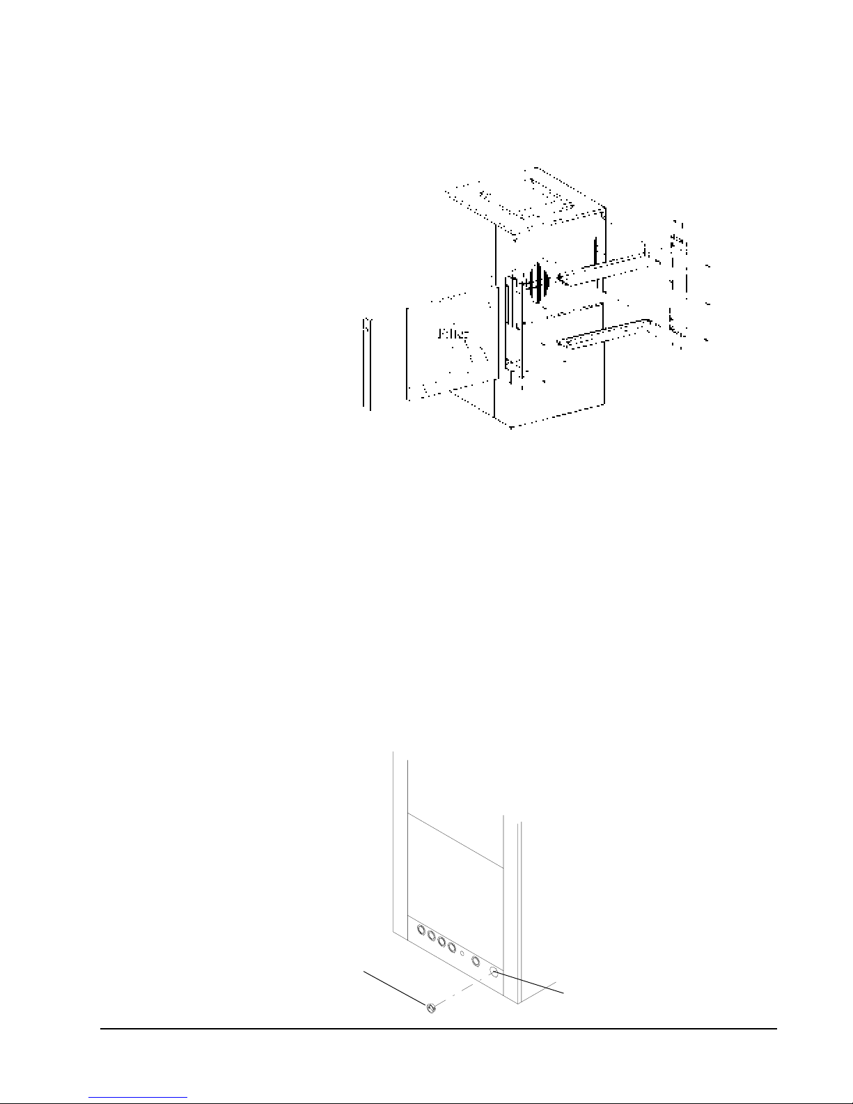
FIGURE 2
PIPING ACCESS TO UNIT
Install 1.750 snap busing
(2 supplied, packed with
installation instructions)
into opening prior to
installation piping.
Remove desired knockout
for piping unit
MIS-381
Manual 2100-250
Page 3

WIRING
All electrical connections are made through the top of the unit. High voltage connections are made with wire
nuts to the factory-provided pigtail leads in the junction box. Low voltage connections are made to the terminal
strip mounted on the top of the unit. Refer to the wiring diagram for connecting the terminals.
MAIN POWER
Refer to the unit serial plate for wire sizing information and correct protection size. Each unit is marked with a
"Minimum Circuit Ampacity ." This means that field wiring connections must be sized to carry that amount of
current. Each unit and/or wiring diagram is also marked "Use Copper Conductors Only ," meaning the leads
provided are not suitable for aluminum wiring. Refer to the National Electric Code for complete currentcarrying capacity data on the various grades of wiring material.
The unit rating plate lists "Maximum Overcurrent Protective Device" that is to be used with the equipment.
This device may be a time delay fuse or HACR type circuit breaker. The correct size overcurrent protective
device must be used to provide for proper circuit protection and to avoid nuisance trips due to the momentary
high starting current of the compressor motor.
THERMOSTAT LOW VOLTAGE WIRING
A 24 volt terminal strip is mounted on top of the unit with an optional terminal board cover included with the unit
installation instructions. See Figure 3. Two types of thermostats are available: 1) Single stage heat, single
stage cool to operate the heat pump alone without backup duct style electric heaters. This thermostat is
equipped with a signal light to indicate when the unit is "locked out" because of the low temperature or high
pressure control. Refer to the wiring diagram 4091-810 for correct connection of the terminals. 2) Two stage
heat, single cool to operate the heat pump or duct heaters on heating or the heat pump on cooling. This
thermostat is also equipped with a signal light to indicate when the unit is "locked out" because of operation of
the low temperature or high pressure control. In addition, a second signal light tells when the unit has been
placed in Emergency Heat. Refer to the wiring diagram 4091-81 1, and to the wiring diagram packed with the
duct heater for correct connection of the low voltage terminals.
Terminal Board
Left Side
FIGURE 3
OPTIONAL TERMINAL BOARD COVER
Remove screws from terminal
board. Place cover in position,
and reinstall screws to secure
cover to board
Terminal board cover packed
with installation instructions)
Right Side
MIS-380
Manual 2100-250
Page 4
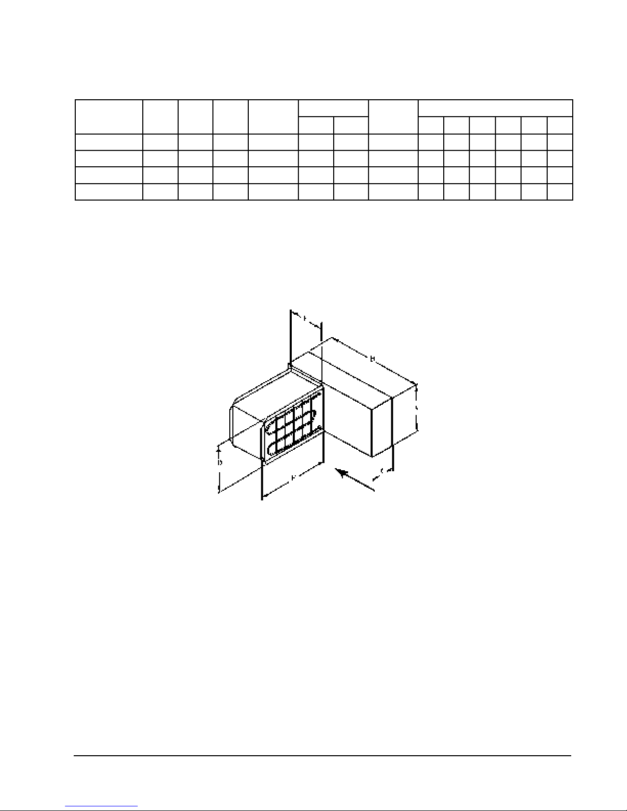
TABLE 4
ACCESSORY ITEMS – DUCT HEATER
(SEE FIGURE 4)
muminiM
.oNtraPHPstloVWK
080-406810420.57201#8#0380147721
180-406810428.9256#4#5580147761
280-4068 k 10427.41874#1#085181511981
380-4068 k 10422.910012#0#0015181511981
j
Use wire suitable for at least 75° C.
k
Fused units (over 48 amperes).
NOTE: All duct heaters are supplied with backup protection and internal fusing as required by NEC.
yticapmA
eziSeriW j
UCLA ABCDEF
mumixaM
esuF
snoisnemiD
FIGURE 4
DUCT HEATER
wpv2.tif
The following is a verbal description of the proper procedure for connecting the low voltage hookups for the
duct heater. (Refer to wiring diagram 4091-811).
1. Black wire from duct heater to C on the 24 volt terminal block.
2. Green wire from duct heater to green wire from thermostat. These wires must be wire nutted and isolated
from the terminal block. Failure to do so will result in improper heater operation.
3. Connect green with tracer from heater to the G terminal on the 24 volt terminal block.
4. Connect the white wire from the heater to W2 on 24 volt terminal block.
A. For the 15 and 20 KW duct heaters, connect the white and white with black tracer wires to W2.
Manual 2100-250
Page 5
ACCESSORIES
ADD-ON DPM26A PUMP MODULE KIT
NOTE: This section applies only if a DPM26A Pump Module is added. Refer to DPM26A instructions for complete
installation details.
GENERAL
This high efficiency water source heat pump series was designed with a refrigerant to water heat exchanger commonly
know as a desuperheater coil factory-installed for ease in installing optional DPMA pump module kit. The addition of
this optional kit allows for heat recovery for hot water heating when connected to a home water heater. The amount of
annual hot water supplied and thus additional energy cost savings will depend on the amount of hot water usage and the
number of hours the heat pump operates. This pump kit is suitable for potable water.
INSTALLATION
1. Follow all local, state, and national codes applicable to the installation of the pump module kit.
2. Follow the installation instructions received with the DPM26A pump module kit.
3. Connect the water lines between the unit, pump module kit, and the water heater.
FIGURE 5
CONNECTION OF WATER LINES
WPV MODEL
WATER TO
WATER
HEATER
WATER TO UNIT
SERVICE
SHUT-OFF
VALVES
DPM26A
WATER FROM
WATER HEATER
SERVICE
SHUT-OFF
VALVE
MIS-1613
Manual 2100-250
Page 6
WATER FROM PUMP KIT

CLOSED LOOP
(Earth Coupled Ground Loop Applications)
NOTE: Low temperature thermostat must be reset from factory setting to 15º for closed
loop applications.
This unit is designed to work on earth coupled ground loop systems, however, these systems operate at
entering water (without antifreeze) temperature well below the temperature normally experienced in water well
system.
For information on earth coupled loop design, piping connections to heat pump and installation refer to manual
2100-099, "Earth Coupled Loop System Design Manual," available from your distributor.
THE CIRCULATION SYSTEM DESIGN
Equipment room piping design is based on years of experience with earth coupled heat pump systems. The
design eliminates most causes of system failure.
Surprisingly , the heat pump itself is rarely the cause. Most problems occur because designers and installers
forget that a closed loop earth coupled heat pump system is NOT like a household plumbing system.
Most household water systems have more than enough water pressure either from the well pump or the
municipal water system to overcome the pressure or head loss in 1/2 inch or 3/4 inch household plumbing. A
closed loop earth coupled heat pump system, however, is separated from the pressure of the household
supply and relies on a small, low wattage pump to circulate the water and antifreeze solution through the earth
coupling, heat pump and equipment room components.
The small circulator keeps the operating costs of the system to a minimum. However, the performance of the
circulator MUST be closely matched with the pressure or head loss of the entire system in order to provide the
required flow through the heat pump. Insufficient flow through the heat exchanger is one of the most common
causes of system failure. Proper system piping design and circulator selection will eliminate this problem.
Bard supplies a worksheet to simplify head loss calculations and circulator selection. Refer to "Circulating
Pump Worksheet" section in manual 2100-099.
Two general methods are used to pipe the water circuit in the equipment room. The first and easiest to use is
to install a pump module. This module comes complete with connecting hose and heat pump adapters
available from Bard. A second method is to "site build" the piping at the installation.
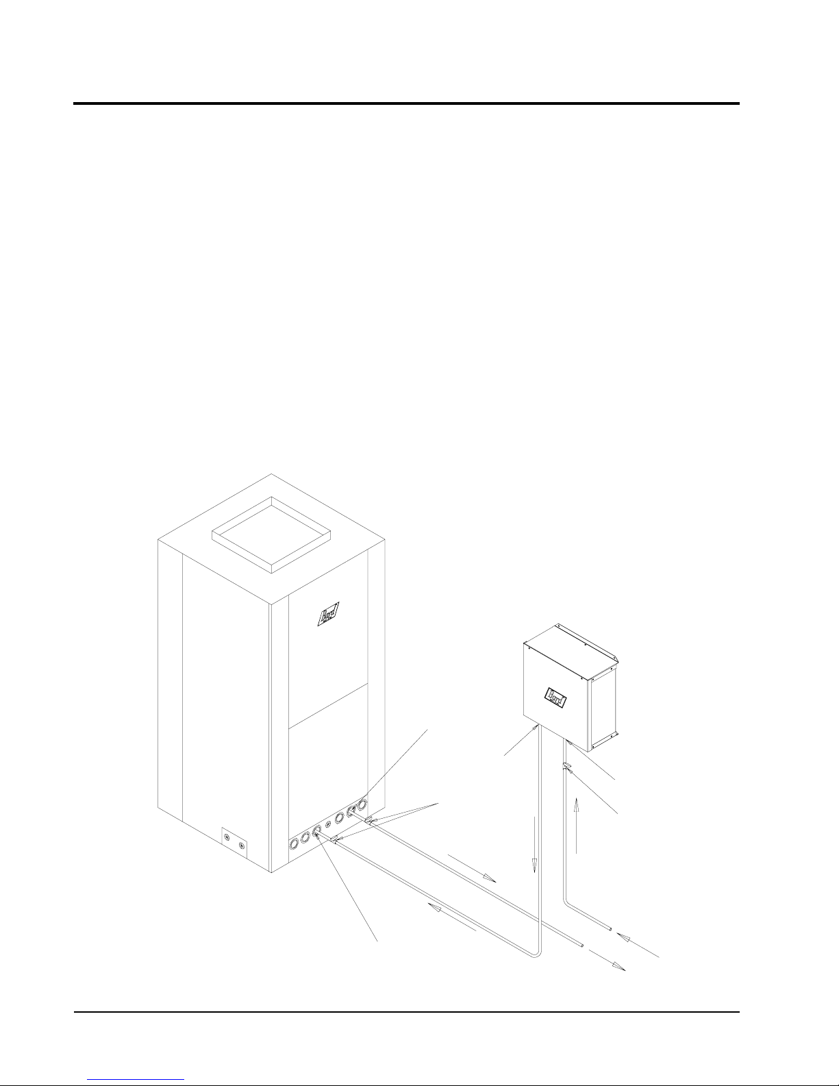
To move the transfer fluid (water or antifreeze and water solution) through the earth loop system and the water
source heat pump, some type of circulation system is required. Design of circulation system must include
provisions for the following. See Figure 6.
1. Selection of a circulation pump or pumps for total system.
2. Providing air bleed off before start-up running.
3. Providing for flow monitoring.
4. Positive pressure control and limiting.
5. Antifreeze charging capability .
NOTE: The expansion and contraction of earth loop piping may cause a 50 to 60 psig water pressure charge
in system between summer to winter.
Manual 2100-250
Page 7
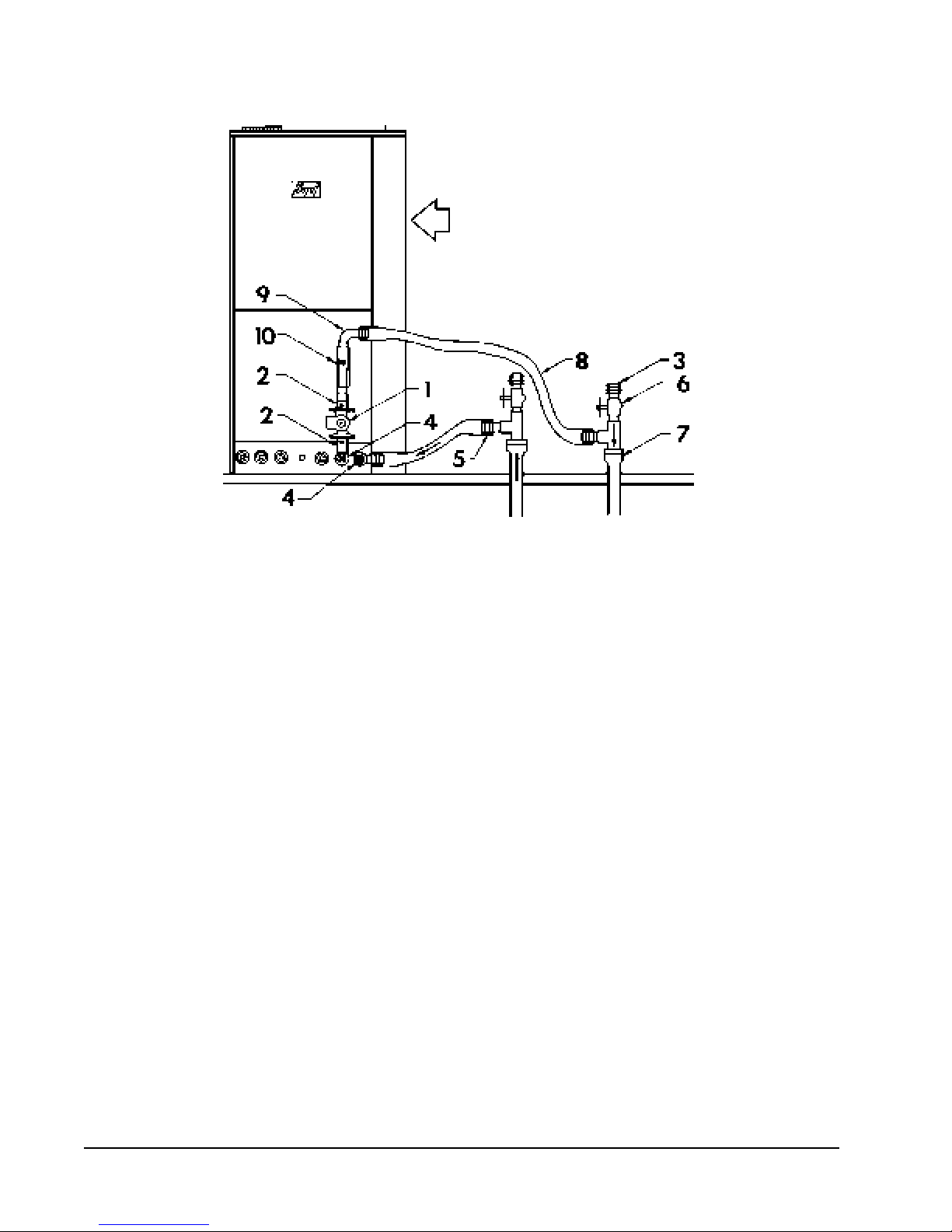
FIGURE 6
COMPONENTS FOR CIRCULATION SYSTEM
RETURN AIR
wpv4.tif
The components for a circulation system are as follows: Refer to Figure 6.
1. Circulating pump systems are engineered for each individual system to provide the correct water flow
and overcome the friction loss of the system piping. Isolation flanges or ball valves are used to insulate
pump from system piping. Y ou need to be able to remove the pump from piping without losing the
transfer fluid for repairs if ever required.
Determining pressure drop and selecting a circulation pump or pumps. It is very important in
selecting the circulating pump that a very accurate pressure drop calculation be made because final
pressure drop at the selected pump must pump against will to determine the actual flow rate (GPM)
that is delivered to the water source heat pump, the pumping cost and efficiency of the entire system.
2. Ball valve and flange
3. Barb X MIP brass adapter
4. Brass test plugs--in order to start up and troubleshoot a closed loop system properly , water in and water
out temperatures at the heat pump must be monitored. A test plug is installed on one leg of each
connection line. A probe thermostat can be temporarily inserted, the temperature monitored and the
thermometer removed. Use one thermometer to monitor these temperatures. Using two different
thermometers to measure the temperature differential can introduce large measurement errors. They
are also used to measure pressure drop to determine coil flow rate.
5. Bard X insert brass adapter
6. Two boiler drains are located on both sides of the circulator for final filling, air purging and antifreeze
addition.
The top drain should be the highest point in the equipment room piping. This will help purge air out of the
system during final filling at start up.
7. PE or PB pipe to fit transition
8. One inch reinforced flexible hose
9. 90º street ell (brass)
10. Flow meter (Bard part No. 8603-017)--or equivalent side to monitor water flow is recommended.
Manual 2100-250
Page 8
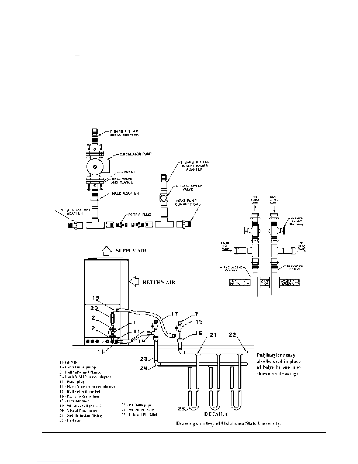
HEAT PUMP CONNECTIONS WITHOUT PUMP KIT
The units have various female connections inside on water coil. To keep losses small, all piping and
components
in the heat pump should be one inch copper or plastic. The transition to one inch pipe should be
made at the exterior of the heat pump if 3/4 inch piping is used in small heat pump models.
Be sure to use a backup wrench when installing the adapters to the heat pump.
PIPING CONNECTIONS
Up to 12 feet of reinforced flexible hose is used. Cut hoses to the desired lengths and install with as few
bends as possible. Close bends increase pipe head loss so any bends should be as wide as possible. Use
the clamps to secure hoses in position.
FIGURE 7
FIGURE 8
FIGURE 9
wpv5.tif
wpv6.tif
wpv7.tif
Manual 2100-250
Page 9
 Loading...