

Bard WL7013B, WL7023A Installation Instructions Manual

INSTALLATION INSTRUCTIONS
WALL MOUNTED
PACKAGE AIR CONDITIONERS
Model
WL7013B
WL7023A
Bard Manufacturing Company, Inc.
Bryan, Ohio 43506
Since 1914...Moving ahead just as planned.
Manual : 2100-428A
Supersedes: 2100-428
File: Volume III Tab 16
Date: 07-25-06
Manual 2100-428A
Page 1 of 18

CONTENTS
Getting Other Information and Publications 3
Wall Mount General Information
Air Conditioning Wall Mount Model Nomenclature .. 4
Shipping Damage .................................................... 6
General ................................................................ 6
Duct Work.......................................................... 6 & 7
Condensate Drain.................................................... 7
Installation Instructions
Wall Mounting Information....................................... 8
Mounting the Unit .................................................... 8
Wiring – Main Power ............................................. 13
Wiring – Low Voltage Wiring ................................. 13
Figures
Figure 1 Unit Dimensions...................................... 5
Figure 2 Mounting Instructions.............................. 9
Figure 3 Electric Heat Clearance ........................ 10
Figure 4 Wall Mounting Instructions.....................11
Figure 5 Wall Mounting Instructions.....................11
Figure 6 Common Wall Mounting Installations.... 12
Figure 7 Unit 24V Terminal Board ....................... 14
Figure 8 Fan Blade Setting ................................. 17
Start Up
Important Installer Note ......................................... 15
Crankcase Heaters................................................ 15
High Pressure Switch ............................................ 15
Three Phase Scroll Compressor Start Up.............. 15
Service Hints ......................................................... 15
Sequence of Operation.......................................... 15
Compressor Control Module.......................... 15 & 16
Adjustments........................................................... 16
Phase Monitor ....................................................... 16
Pressure Service Ports.......................................... 16
Troubleshooting
Fan Blade Setting Dimensions .............................. 17
Removal of Fan Shroud......................................... 17
Refrigerant Charge ................................................ 17
Pressure Table....................................................... 18
Tables
Table 1 Electric Heat Table .................................. 4
Table 2 Electrical Specifications .......................... 6
Table 3 Thermostat Wire Size ........................... 13
Table 4 Wall Thermostat.................................... 13
Table 5 Fan Blade Dimensions.......................... 17
Table 6 Indoor Blower Performance .................. 17
Table 7 Refrigerant Charge ............................... 17
Table 8 Rated CFM and Rated ESP.................. 17
Table 9 Maximum ESP of Operation
Electric Heat Only ................................. 17
Table 10 Pressure Table ...................................... 18
Manual 2100-428A
Page 2 of 18

Getting Other Information and Publications
These publications can help you install the air conditioner
or heat pump. You can usually find these at your local
library or purchase them directly from the publisher. Be
sure to consult current edition of each standard.
National Electrical Code........................ANSI/NFPA 70
Standard for the Installation...................
of Air Conditioning and Ventilating Systems
Standard for Warm Air ..........................
Heating and Air Conditioning Systems
Load Calculation for .............................. ACCA Manual J
Residential Winter and Summer Air Conditioning
Duct Design for Residential...................ACCA Manual
D Winter and Summer Air Conditioning and Equipment
Selection
ANSI/NFPA 90A
ANSI/NFPA 90B
For more information, contact these
publishers:
ACCA Air Conditioning Contractors of America
1712 New Hampshire Ave. N.W.
Washington, DC 20009
Telephone: (202) 483-9370
Fax: (202) 234-4721
ANSI American National Standards Institute
11 West Street, 13th Floor
New York, NY 10036
Telephone: (212) 642-4900
Fax: (212) 302-1286
ASHRAE American Society of Heating Refrigerating,
and Air Conditioning Engineers, Inc.
1791 Tullie Circle, N.E.
Atlanta, GA 30329-2305
Telephone: (404) 636-8400
Fax: (404) 321-5478
NFPA National Fire Protection Association
Batterymarch Park
P.O. Box 9101
Quincy, MA 02269-9901
Telephone: (800) 344-3555
Fax: (617) 984-7057
Manual 2100-428A
Page 3 of 18
WALL MOUNT GENERAL INFORMATION
AIR CONDITIONING WALL MOUNT MODEL NOMENCLATURE
WL 70 2 3 A 10 B N X X X A
MODEL NUMBER CONTROL
CAPACITY
70 - 6 Ton
REVISIONS
FEATURE CODE
3 - 3 ton air openings
on 5 ton cabinet
VOLTS & PHASE
A - 230/208/60/1
B - 230/208/60/3
VENTILATION OPTIONS
B - Blank-off Plate
KW
FILTER OPTIONS
N - No Filter
COLOR OPTIONS
X - Beige (Standard)
1 - White
2 - Mesa Tan
4 - Buckeye Gray
MODULES
COIL OPTIONS
X - Standard
1 - Phenolic Coated Evaporator
2 - Phenolic Coated Condenser
3 - Phenolic Coated Evaporator
and Condenser
OUTLET OPTIONS
X - Front (Standard)
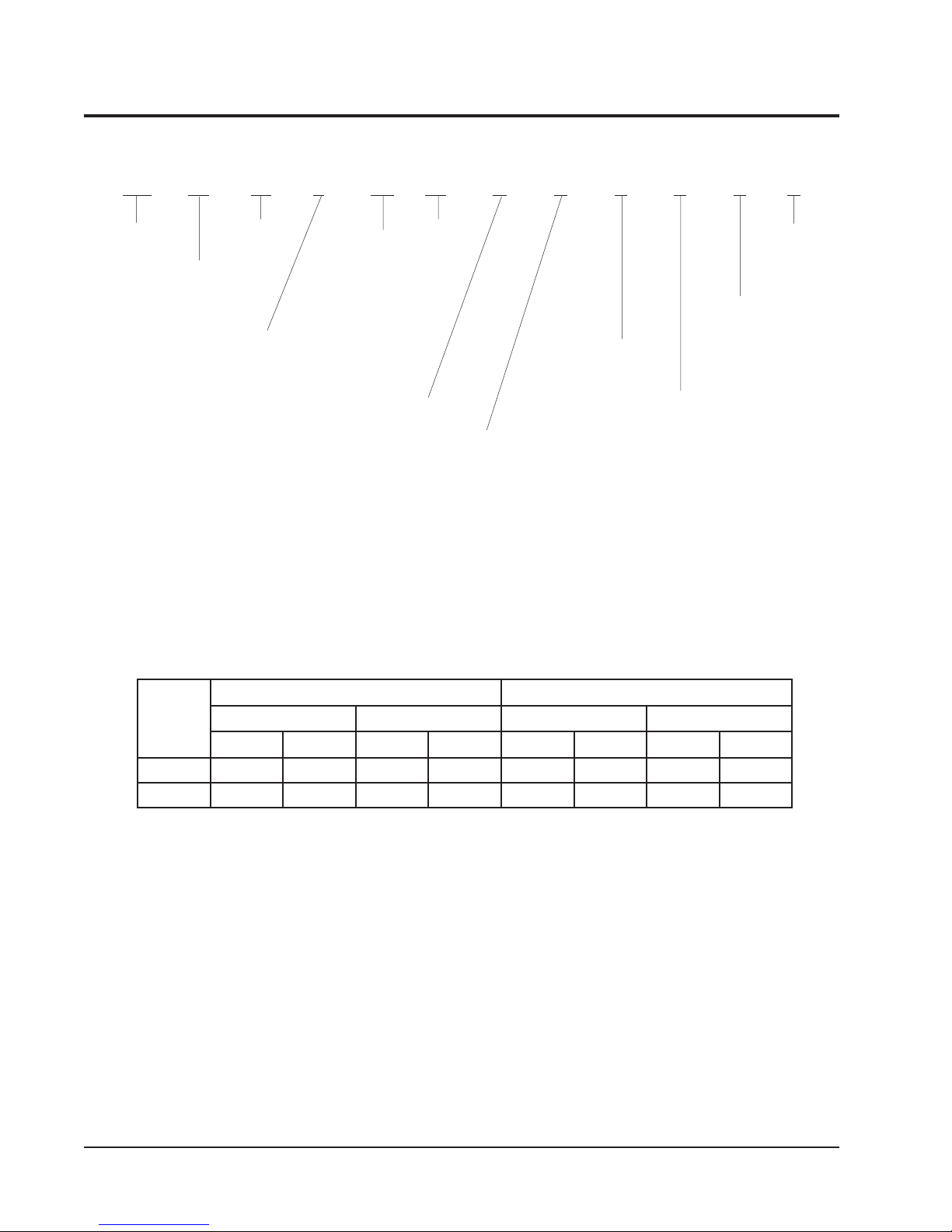
TABLE 1
ELECTRIC HEAT TABLE
sledoM
YLNOA3207LWYLNOB3107LW
1-V0421-V8021-V0421-V802
WK
SPMAHUTBSPMAHUTBSPMAHUTBSPMAHUTB
0.9------------7.12006,037.81030,32
0.016.14031,432.63006,52------------
Manual 2100-428A
Page 4 of 18
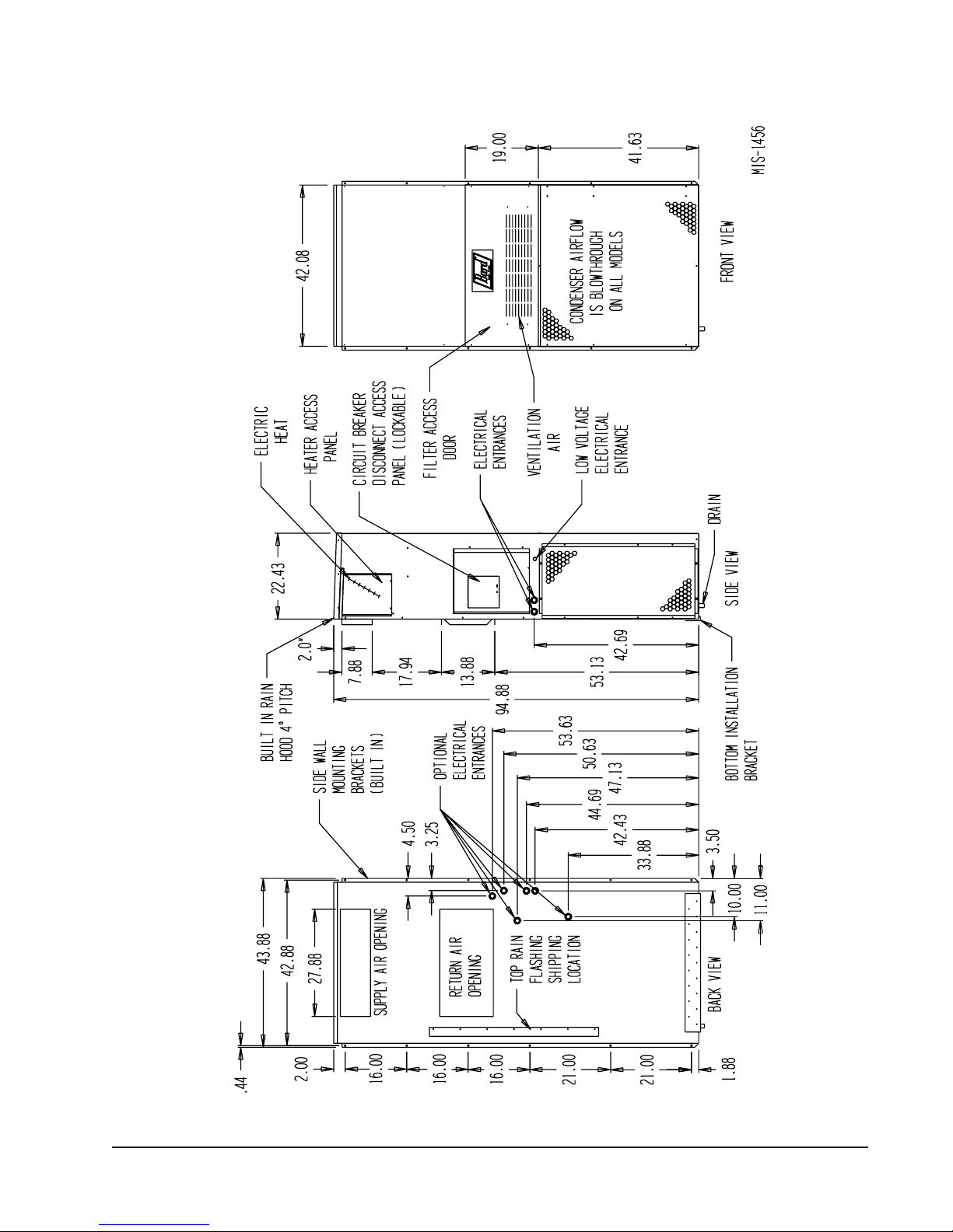
FIGURE 1
UNIT DIMENSIONS
Manual 2100-428A
Page 5 of 18
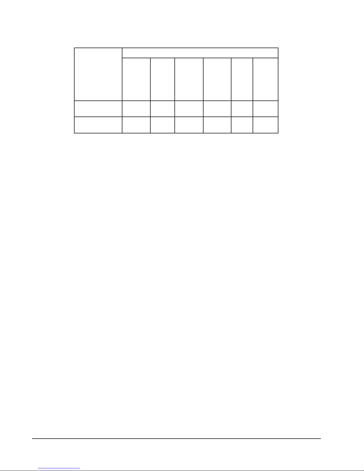
TABLE 2
ELECTRICAL SPECIFICATIONS
TIUCRICELGNIS
detaR
&stloV
ledoM
Z0A3207LW
01A
Z0B3107LW
90B
1 Maximum size of the time delay fuse or HACR type circuit breaker for protection of field wiring conductors.
2 Based on 75° C copper wire. All Wiring must conform to NEC and all local codes.
3 These “minimum Circuit Ampacity” values are to be used for sizing the field power conductors. Refer to the
National Electric Code (latest revision), article 310 for power conductor sizing.
CAUTION: When more than one field power conductor circuit is run through one conduit, the conductors
must be derated. Pay special attention to note 8 of table 310 regarding Ampacity Adjustment
Factors when more than 3 conductors are in a raceway.
esahP
1-802/032
3-802/032
SHIPPING DAMAGE
Upon receipt of equipment, the carton should be
checked for external signs of shipping damage. If
damage is found, the receiving party must contact the
last carrier immediately, preferably in writing,
requesting inspection by the carrier’s agent.
GENERAL
The equipment covered in this manual is to be installed
by trained, experienced service and installation
technicians.
The refrigerant system is completely assembled and
charged. All internal wiring is complete.
The unit is designed for use with or without duct work.
Flanges are provided for attaching the supply and return
ducts.
These instructions explain the recommended method to
install the air cooled self-contained unit and the
electrical wiring connections to the unit.
While these instructions are intended as a general
recommended guide, they do not supersede any national
and/or local codes in any way. Authorities having
jurisdiction should be consulted before the installation is
made. See Page 3 for information on codes and
standards.
3
.oN
dleiF
rewoP
stiucriC
1
1
1
1
muminiM
tiucriC
84
95
63
63
1
.tkC
yticapmA
06
06
05
05
2
mumixaM
lanretxE
roesuF
rekaerB
8
6
8
8
2
dleiF
rewoP
eriW
eziS
dnuorG
eriW
eziS
01
01
01
01
Size of unit for a proposed installation should be based
on heat loss calculation made according to methods of
Air Conditioning Contractors of America (ACCA). The
air duct should be installed in accordance with the
Standards of the National Fire Protection Association
for the Installation of Air Conditioning and Ventilating
Systems of Other Than Residence Type, NFPA No.
90A, and Residence Type Warm Air Heating and Air
Conditioning Systems, NFPA No. 90B. Where local
regulations are at a variance with instructions, installer
should adhere to local codes.
DUCT WORK
All duct work, supply and return, must be properly sized
for the design airflow requirement of the equipment.
Air Conditioning Contractors of America (ACCA) is an
excellent guide to proper sizing. All duct work or
portions thereof not in the conditioned space should be
properly insulated in order to both conserve energy and
prevent condensation or moisture damage.
These instructions and any instructions packaged with
any separate equipment, required to make up the entire
air conditioning system should be carefully read before
beginning the installation. Note particularly any tags
and/or labels attached to the equipment.
Manual 2100-428A
Page 6 of 18
 Loading...