

THE WALL-MOUNT™ STEP CAPACITY GAS/ELECTRIC - WG*S SERIES
Integrated Part Load Value (IPLV) Efficiency Up to 15.5 BTU/WATT
WG3S1, WG4S1, WG5S1 60HZ
GREEN REFRIGERANT
23,000 to 56,500 BTUH Cooling Capacity
36,000 to 99,000 BTUH Heating Capacity
The Bard Wall-Mount Electric Air Conditioner with gas fired heating is a self contained energy efficient system
which is designed to offer maximum indoor comfort at a minimal cost without using valuable indoor floor space
or outside ground space. This unit is the ideal product for versatile applications such as: new construction,
modular offices, school modernization, portable structures, correctional facilities, retail stores or other
commercial applications. Factory or field installed accessories are available to meet specific job requirements.
Engineered Features
Multi-Capacity Two-Stage:
Simple thermostatic control seamlessly
stages the compressor and indoor airflow
rate between high and low capacity
operations without cycling the compressor.
This helps to maximize comfort, humidity
control, energy efficiency and overall
reduction in compressor cycling for
improved system life.
Step Capacity Compressor:
Copeland step-capacity (2-stage) scroll
compressors are designed for increased
efficiency, quieter operation and improved
reliability for longer life.
R-410A Refrigerant:
Designed with R-410A (HFC) non-ozone
depleting refrigerant in compliance with
the Montreal protocol and 2010 EPA
requirements.
Thermal Expansion Valves:
All models use TXV.
Liquid Line Filter Drier:
Protects system against moisture.
Aluminum Finned Copper Coils:
Grooved tubing and enhanced louvered
fin for maximum heat transfer and energy
efficiency.
High & Low Pressure Switches are
Auto-Reset
Built-in lockout circuit resets from the
room thermostat. Provides commercial
quality protection to the compressor.
Compressor Control Module:
Standard on all units. Built-in off-delay
timer adjustable from 30 seconds to 5
minutes. 2-minute on-delay if power
interrupt. 120-second bypass for low
pressure control, and both soft and
manual lockouts for high and low pressure
controls. Alarm output for alarm relay.
Crankcase Heaters:
Factory installed crankcase heaters are
standard on all models. This helps to
insure ease of start at low temperatures
and improves compressor life.
• Complies with efficiency requirements of ANSI/ASHRAE/IESNA 90.1-2007.
• Certified to ANSI/ARI Standard 390-2003 for SPVU (Single Package Vertical Units).
• Intertek ETL Listed to Standard for Safety Heating and Cooling Equipment ANSI/UL
1995/CSA 22.2 No. 236-05, Third Edition.
• Intertek ETL Listed to Standard for Gas-Fired Central Furnaces ANSI Z21.47-2006, CSA
2.3-2006 Fifth Edition, Addenda A dated 10-01-2007, Addenda B dated 06-01-2008.
• Commercial Product - Not intended for Residential application.
Phase Rotation Monitor:
Standard on all 3 phase scroll
compressors. Protects against reverse
rotation if power supply is not properly
connected.
Twin Blowers:
Move air quietly. All models feature
variable speed blower motors providing
automatic airflow adjustment for high
static or free blow (non-ducted) operation
at a very low sound level. Motor overload
protection is standard on all models.
ECM Indoor Blower Motor:
Features a variable speed motor
providing super-high efficiency, low
sound levels and soft-start capabilities.
The motor is self-adjusting to provide the
proper airflow rate for the staged
capacity, and for higher static pressure in
ducted installations without user
adjustment or wiring changes.
Ventilation Controller:
Automatically adjusts damper position to
maintain the desired ventilation airflow rate
up to 480 cfm of fresh air during any
operation mode. Fully closes during
unoccupied modes. Factory set for 480
cfm. Also, CO2 sensor ready - just add
CO2 sensor for demand ventilation based
on CO2 level in the space.
Electrical Components:
Are easily accessible for routine inspection
and maintenance through a right side,
service panel opening. Features a
lockable, hinged access cover to the circuit
breaker or rotary disconnect switch.
PTCR Start Assist:
Standard on 1-phase models.
Heat Exchanger:
Heavy duty 18-gauge stainless steel
tubular heat exchanger. Mechanically
joined construction. Ten-year warranty.
In-Shot Burners:
Advanced burner design, quiet operation.
Low NOx models available. Low NOx
models can be converted to LP gas. High
altitude kits available.
R-410A
MEA # (Heating): 73-03-E
MEA # (Cooling): 179-03-E
Integrated DSI Control:
Direct spark ignition control and
remote sensor delivers smooth,
proven ignition sequence.
Timed blower control and
diagnostics are also features of
integrated control.
Gas Controls:
Honeywell gas valve and
burner orifices are factory
standard for natural gas. Field
convertible to LP gas with
certified conversion kit.
Hinged Service Door:
Hinged door with compression latches (one lockable) for filter
service access, heat exchanger inspection, and indoor blower/
motor service.
Pre-Painted 20 Gauge Zinc Coated Steel Cabinet:
Cleaned, rinsed, sealed and dried before the polyurethane
primer is applied. The cabinet is handsomely finished with a
baked on textured enamel, which allows it to withstand 1000
hours of salt spray tests per ASTM B117-03.
16 Gauge Zinc Coated Unit Base
Two-Inch, Pleated Disposable Air Filters:
Are standard equipment.
Condenser Fan and Motor
Shroud Assembly:
Slides out for easy access.
Circuit Breakers/Rotary Disconnect:
Standard on all versions of single (230/208 volt) and three
phase (230/208 volt) equipment. Rotary disconnects are
standard on all versions of three phase (460 volt) equipment.
Slope Top:
Standard feature for water run-off.
Full Length Mounting Brackets:
Built into cabinet for improved appearance and easy installation.
Top Rain Flashing:
Standard feature on all models.
Ventilation Options:
Several patented ventilation options are available and can be
factory or field installed.
• High Efficiency
• Low Sound Level
Form No. S3396-1112
Supersedes S3396-212
Page 1 of 12
M
E
O
M
G
C
C
V
R
B
L
F
F
F
F
M
B
B
C
C
F
C
S
C
M
C
E
R
C
E
R
I
Specifications
H
F
M
I
O
A
T
C
1
M
I
O
A
T
C
ledo
zH06-gnitaRcirtcel
egnaRegatloVgnitarep
yticapmAtiucriCmumini
eziSeriWdleiF*80141801218801
eziSeriWdnuor
.xaM-esuFyaleD**540351540402060552
rosserpmo
epyTrosserpmo
stlo
spmAdaoLdeta
tnerruCnoitceleStiucriChcnar
spmArotoRdekco
resnednoC&rotoMna
DPS/MPR/PH-rotoMna
spmArotoMna
MFC/.AIDna
rotaropavE&roto
DPS/MPR/PH-rotoMrewol
spmA-rotoMrewol
egatSts1-gnilooCMF
egatSdn2-gnilooCMF
eziSretli
)A014-R(egrah
).sbl(thgieWgnippih
1
* Based on 75°C copper wire. All wiring must conform to the National Electrical Code and all local codes.
** Maximum time delay fuse or HACR type circuit breaker.
1 Add 45 lbs. for factory installed WGSCRVMP-5 Commercial Room Ventilator or WGSEIFM-5 Economizer, and 90 lbs. for WGSERV-5 Energy Recovery Ventilator.
A-1S3GW B-1S3GW C-1S3GW A-1S4GW B-1S4GW C-1S4GW A-1S5GW B-1S5GW C-1S5GW
1-06-802/0323-06-802/0323-06-0641-06-802/0323-06-802/0323-06-0641-06-802/0323-06-802/0323-06-064
352-791352-781605-414352-791352-781605-414352-791352-781605-414
133211838241444371
010141010121010101
llorcSllorcSllorcSllorcSllorcSllorcSllorcSllorcSllorcS
802/032802/032064802/032802/032064802/032802/032064
3.31/4.112.8/5.63.34.71/0.511.11/4.95.41.32/8.910.51/4.317.6
7.612.115.42.125.315.67.526.815.9
28859269881481132126
2-058-3/12-058-3/11-058-3/12-058-3/12-058-3/11-058-3/12-058-3/12-058-3/11-058-3/1
5.25.23.15.25.23.15.25.23.1
0072-"420072-"420072-"420072-"420072-"420072-"420072-"420072-"420072-"42
elbairaV2/1elbairaV2/1elbairaV2/1elbairaV4/3elbairaV4/3elbairaV4/3elbairaV4/3elbairaV4/3elbairaV4/3
6.36.36.37.47.47.40.60.60.6
008008008001100110011003100310031
001100110011005100510051007100710071
2x03x022x03x022x03x022x03x022x03x022x03x022x03x022x03x022x03x02
651651651042042042642642642
585 585 036 586 586 037 017 017 557
ledo
noitarepOegatSdn2,HUTByticapaCgniloo
1 006,43005,64005,65
1 8.015.117.01
noitarepOegatSdn2RE
lioCteW,MFCdeta
noitarepOegatSts1,HUTByticapaCgniloo
noitarepOegatSts1RE
lioCteW,MFCdeta
)3002-093dradnatSIRAotdeifitreC(VLP
edoCtupnIgnitaeHledo
HUTBtupn
2 005,04 000,16 000,18 000,99
)yticapaCgnitaeH(HUTBtuptu
2 0.18 0.18 0.18 0.18
EUF
)F(egnaResiRerutarepme
)F(esiRtnatsnoC/MFCgnitaeHtnatsno
edoCtupnIgnitaeHledo
HUTBtupn
2 000,63 005,45 000,27 005,78
)yticapaCgnitaeH(HUTBtuptu
2 0.18 0.18 0.18 0.18
EUF
)F(egnaResiRerutarepme
)F(esiRtnatsnoC/MFCgnitaeHtnatsno
1 .ledomhcaerofdetcelesebnactupniynA
2 .margorPnoitacifitreCycneiciffEAMAGhtiwecnadroccanideifitrecsgnitargnitaeH
Form No. S3396-1112
Supersedes S3396-212
Page 2 of 12
A B C D
000,05 000,57 000,001 000,521
55-52 06-03 07-04 08-05
53/069 05/0011 05/5631 07/0441
A B C D
000,54 005,76 000,09 005,211
55-52 06-03 07-04 08-05
03/069 54/0011 54/5631 56/0441
1S3GW 1S4GW 1S5GW
001100410061
000,32006,33005,04
8.012.210.11
00800110031
0.415.513.41
etoNeeS—ecnamrofreP&snoitpOyticapaCgnitaeHetareDdleiF%0
etoNeeS—ecnamrofreP&snoitpOyticapaCgnitaeHdradnatSyrotca
11
11 woleB
1
11
11 woleB
1
sgnitaRwolfriA&ycneiciffE,yticapaCmetsySgniloo
sgnitaRwolfriA&ycneiciffE,yticapaCmetsySgnitae
Indoor Blower Performance 1
detaR
LEDOM
PSE
xaM
PSE
suounitnoC
MFC
1S3GW51.005.00080080011069001156310441
1S4GW02.005.052800110041069001156310441
1S5GW02.005.005800310061069001156310441
2
3
detaR
egatSts1
MFCgnilooC
4
detaR
egatSdn2
MFCgnilooC
000,05
UTB
tupnI
1 Motor will deliver consistent CFM through voltage supply range with no deterioration (197-253V for 230/208V models, 414-506V for 460V models).
2 Continuous CFM is the total air being circulated during continuous (manual) fan mode.
3 Will occur automatically with a call for “Y1” signal from thermostat.
4 Will occur automatically with a call for “Y2” signal from thermostat.
5 Will occur automatically with a call for “W” signal from thermostat.
6 Constant CFM of Variable Speed Motor should maintain mid-rise temperature differential through range of allowable static.
MFCgnitaeH 65
000,57
UTB
tupnI
000,001
UTB
tupnI
000,521
UTB
tupnI
Ventilation System Packages
Bard Wall-Mounts are designed to provide optional ventilation packages to meet all of your ventilation and indoor air quality requirements.
All units are equipped with a barometric fresh air damper as the standard ventilation package. All ventilation packages can be built-in at the
factory, or field-installed at a later date.
BLANK OFF PLATE - WGSBOP STANDARD
A blank off plate is installed on the inside of the service door. It covers the air inlet openings which restricts any outside
air from entering the unit. The blank off plate should be utilized in applications where outside air is not required to be
mixed with the conditioned air.
COMMERCIAL ROOM VENTILATOR - WGSCRVMP-5 OPTIONAL
The built-in commercial room ventilator is internally mounted behind the service door and allows outside ventilation air,
up to 50% of the total airflow rating of the unit, to be introduced through the air inlet openings. It includes a built-in
exhaust air damper with integral bug screen. Automatic control is integrated to maintain desired ventilation air at the
various supply airflows while on Stage 1, Stage 2 or ventilation modes of operation.
The commercial room ventilator (CRV) is a simple and innovative approach to improving the indoor air quality by
providing fresh air intake and exhaust capability through the CRV. The damper can be easily adjusted to control the
COMMERCIAL ROOM VENTILATOR
amount of fresh air supplied into the building. The CRV can be controlled by indoor blower operation or field controlled
based on room occupancy. The CRV is power open - spring return on power loss. Complies with ANSI/ASHRAE
Standard 62.1 “Ventilation for Acceptable Indoor Air Quality”.
CO
Sensor Ready: • WGSCRVMP-5 is designed for CO2 based on ventilation control
2
by simply wiring in a field installed CO2 sensor if desired.
ECONOMIZER - WGSEIFM-5 OPTIONAL
The built-in economizer system is internally mounted behind the service door and allows outdoor air to be introduced
through the air inlet openings. The amount of outdoor air varies in response to the system controls and settings defined
by the end user. It includes a built-in exhaust air damper. The economizer is designed to provide “free cooling” when
outside air conditions are cool and dry enough to satisfy cooling requirements without running the compressor. This in
turn provides lower operating costs, while extending the life of the compressor.
Standard Features:
• One Piece Construction - Easy to install with no mechanical linkage adjustment required.
ECONOMIZER
• Exhaust Air Damper - Built in with positive closed position. Provides exhaust air capability to prevent
pressurization of tight buildings.
• Actuator Motor - 24 volt, power open, spring return with built in torque limiting switch.
• Proportioning Type Control - for maximum “free cooling” economy and comfort.
• Moisture Eliminator & Prefilter - permanent, washable aluminum construction.
• Enthalpy Control - adjustable to monitor outdoor temperature and humidity.
• Minimum Position Potentiometer - adjustable to control minimum damper blade position for ventilation purposes.
• Mixed Air Sensor - to monitor outside and return air to automatically modulate damper position.
WALL-MOUNT ENERGY RECOVERY VENTILATOR - WGSERV-5 OPTIONAL
The wall-mount energy recovery ventilator (WGSERV-5) is a highly innovative approach to address indoor air quality ventilation
requirements as established by ANSI/ASHRAE Standard 62.1. The WGSERV-5 allows up to 450 CFM (depending upon
speed setting) of fresh air and exhaust through the unit while maintaining superior indoor comfort and humidity levels. In most
cases this can be accomplished without increasing equipment sizing or operating costs. Heat transfer efficiency is up to 74%
during summer and 80% during winter conditions.
The WGSERV-5 consists of a unique “rotary energy recovery cassette” that provides effective sensible and latent heat
transfer capabilities during summer and winter conditions. Various control schemes are addressed including limiting ventilation
ENERGY RECOVERY VENTILATOR
during building occupancy only.
The WGSERV-5 is designed to be internally mounted behind the service door in the WGS Gas/Electric units. It can be builtin at the factory or field installed as an option. WGSERV-5 can be independently adjusted for intake and exhaust rates.
Manufactured under U.S. Patent Nos. 5,301,744; 5,485,878
NOTE: See Page 4 for WGSCRV Performance Data &
Page 5 & 6 for WGSERV Performance Data
Form No. S3396-1112
Supersedes S3396-212
Page 3 of 12
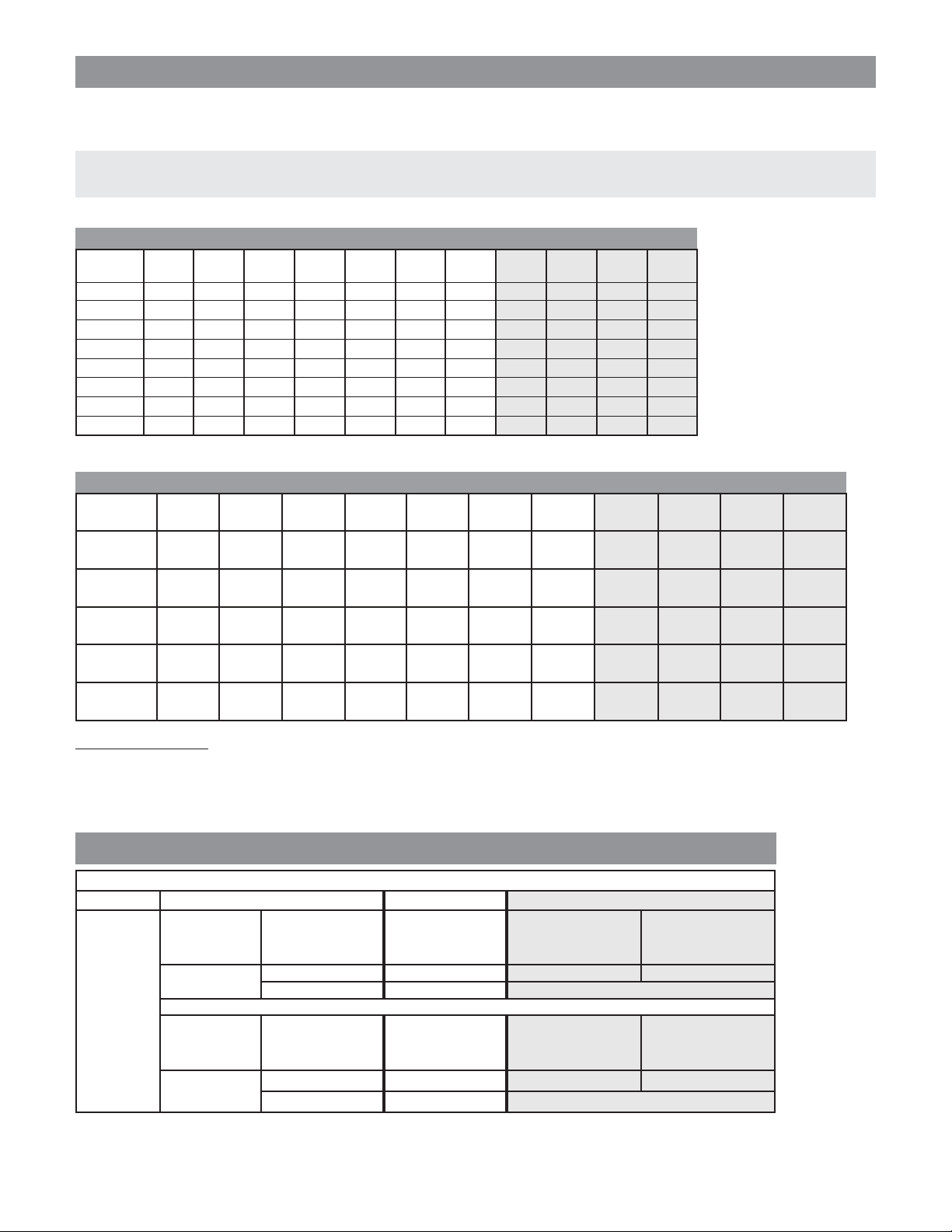
WGSEIFM-5 Economizer and WGSCRVMP-5 Commercial Ventilator Airflow
700
600
500
400
300
Ventilation Airflow (CFM)
200
100
0
0 2.5 5 7.5 10 12.5 15 17.5 20 22.5 25 27.5 30
Vent Position
WG4S Ventilation Airflow
900
800
700
WG3S Ventilation Airflow
Stage #2
Operation
Blower Only
& Stage #1
Operation
600
500
400
Ventilation Airflow (CFM)
300
200
100
0
0 2.5 5 7.5 10 12.5 15 17.5 20 22.5 25 27.5 30
Vent Position
WG5S Ventilation Airflow
1000
900
800
700
600
500
400
Ventilation Airflow (CFM)
300
200
Stage #2
Operation
Stage #1
Operation
Blower Only
Stage #2
Operation
Stage #1
Operation
Blower Only
Form No. S3396-1112
Supersedes S3396-212
Page 4 of 12
100
0
0 2.5 5 7.5 10 12.5 15 17.5 20 22.5 25 27.5 30
Vent Position
Energy Recovery Ventilator Performance Data — WGSERV-A5 (230V) & WGSERV-C5 (460V)
A5C-,A5A-VRESGW—ATADNOITACILPPA
ECNAMROFREPGNILOOCREMMUS
)BW°26/BD°57SNOITIDNOCNGISEDROODNI(
tneibmA
.D.O
/BD
F TLV SLV LLV TRH SRH LRH TLV SLV LLV TRH SRH LRH TLV SLV LLV TRH SRH LRH
BW
575641208541488697821847813149467188911166524901334701536533127094824845860852472
501
0708541085410847884780 88911889110334733470270927090608560850
5608541085410
08 00513 05121 04491 00981 0927 01611 00952 0999 01951 85061 4916 4689 00691 0657 04021 44521 8384 6077
57 56412 05121 4139 97821 0927 9855 94671 0999 9567 24901 4916 9474 65331 0657 6975 8458 8384 9073
001
07 25321 05121 202 1147 0927 121 65101 0999 661 7926 4916 301 6867 0657 621 9194 8384 08
56 05121 05121 0 0927 0927 0 0999 0999 0 4916 4916 0 0657 0657 0 8384 8384 0
06 05121 05121 0 0927 0927 0 0999 0999 0 4916 4916 0 0657 0657 0 8384 8384 0
0809513027907812459812385221314795229972897140161559494111656918406806310852117839078
57564120279447119782123857407946712997756924901559478956533184068037845817837764
59
0725321027923621147238597516510129974612792655942431686784068361919417838401
56027902790238523850299729970
06027902790238523850299729970559455940840684060178317830
08 09513 0927 00342 45981 4734 08541 47952 4995 08991 40161 6173 88321 65691 6354 02151 08521 3092 7769
57 56412 0927 57141 97821 4734 5058 94671 4995 55611 24901 6173 6227 65331 6354 0288 8458 3092 5465
07 25321 0927 2605 1147 4734 7303 65101 4995 2614 7926 6173 0852 6867 6354 0513 9194 3092 6102
09
56 0927 0927 0 4734 4734 0 4995 4995 0 6173 6173 0 6354 6354 0 3092 3092 0
06 0927 0927 0 4734 4734 0 4995 4995 0 6173 6173 0 6354 6354 0 3092 3092 0
08095130684037624598161928306147952699387912401618742626316569142032366108521539144601
5756412068450661978216192369994671699335631249018742564865331420323301845853912166
58
0725321068429471147619259446510169930616792687429183686742032664919453913892
56068406840
06068406840619261920699369930874287420420342030 539153910
57 56412 0342 53091 97821 8541 12411 94671 8991 15651 24901 9321 4079 65331 2151 44811 8458 869 0857
07 25321 0342 2299 1147 8541 3595 65101 8991 8518 7926 9321 8505 6867 2151 4716 9194 869 1593
08
56 2524 0342 2281 1552 8541 3901 6943 8991 8941 8612 9321 929 6462 2151 4311 3961 869 627
06 0342 0342 0 8541 8541 0 8991 8991 0 9321 9321 0 2151 2151 0 869 869 0
07253210 2532111470 114765101065101792607926686706867919409194
57
5625240252415520 1552694306943861208612646206462396103961
06000000000000000000
MFC054--ETARNOITALITNEV
)kcalB(deepShgiH
YCNEICIFFE%06
847884780 88911889110334733470270927090608560850
619261920699369930874287420420342030
MFC073--ETARNOITALITNEV
)eulB(deepSmuideM
YCNEICIFFE%26
559455940840684060178317830
)deR(deepSwoL
YCNEICIFFE%46
539153910
MFC082--ETARNOITALITNEV
LEGEND:
VLT = Ventilation Load - Total
VLS = Ventilation Load - Sensible
VLL = Ventilation Load - Latent
HRT = Heat Recovery - Total
HRS = Heat Recovery - Sensible
HRL = Heat Recovery - Latent
WVL = Winter Ventilation Load
WHR = Winter Heat Recovery
ECNAMROFREPGNITAEHRETNIWA5C-,A5A-VRESGW
)BDF°07SNOITIDNOCNGISEDROODNI(
ETARNOITALITNEV
tneibmA
.D.O
MFC054
.FFE%77
MFC073
.FFE%87
F°/BD LVW RHW LVW RHW LVW RHW
56034207810002065101510911
06068404730004021302030932
55092701650995086404540853
05027908470008032605060874
540512106390999097706570795
04085410321109911053907090717
5301071001910993101901085010638
0304491079410895107421001210659
52078120486108971030410163105701
02003420178108991085510215105911
51037620850208912041710366104131
MFC082
.FFE%97
.noitacilpparetniwrofnwohssiylnoecnamrofrepelbisneS:ETON
Form No. S3396-1112
Supersedes S3396-212
Page 5 of 12

This page intentionally left blank.
Form No. S3396-1112
Supersedes S3396-212
Page 6 of 12
4
0
6
0
0
8
0
0
0
0
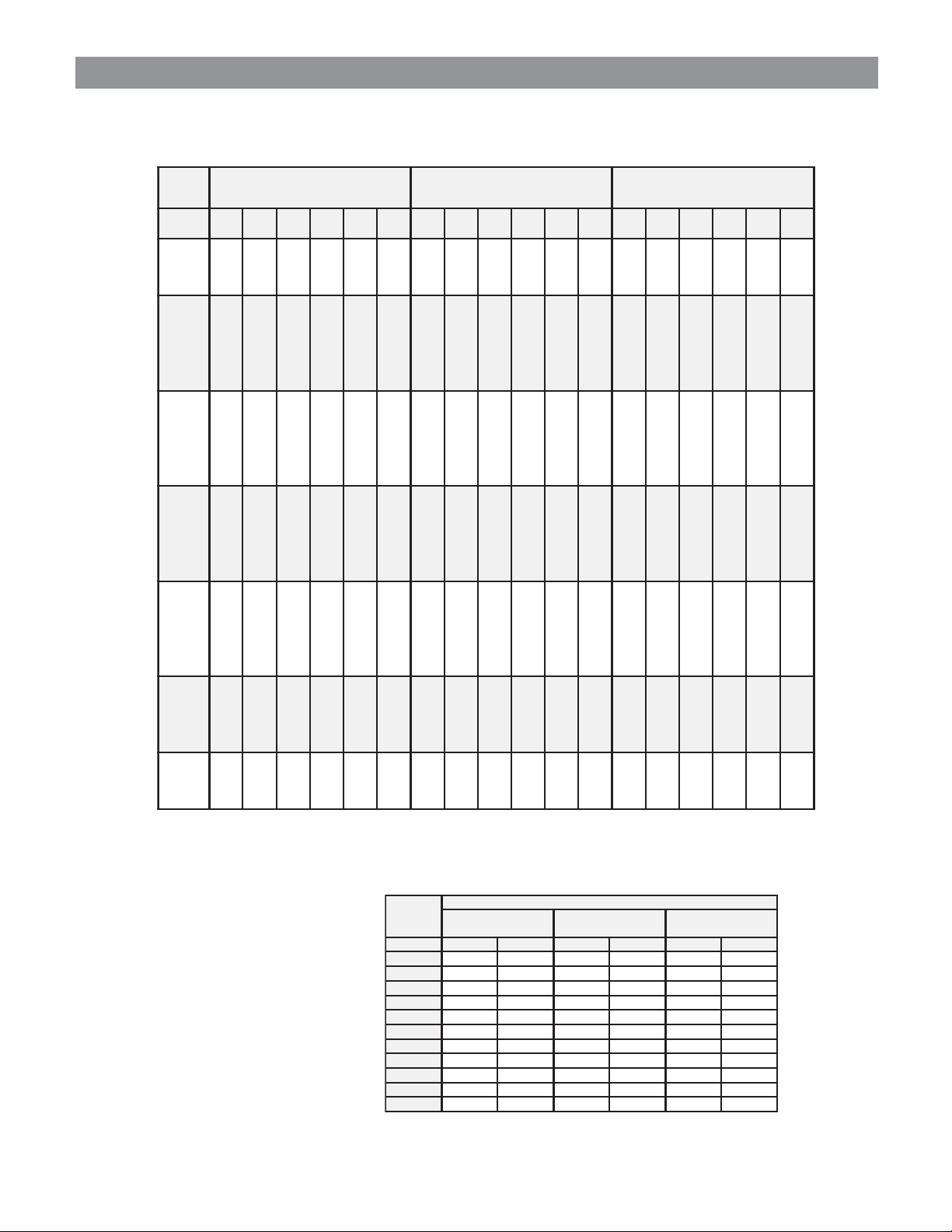
Important Information Concerning Altitude Impact on Heating Input Ratings
Heating input, and thus heating output, decreases with altitude. No orifice change is required up to 6,000 feet elevation and derate occurs naturally due
to altitude impact. Natural gas models may require orifice change based on BTU content of gas. See Natural Gas Orifice and Altitude Tables on
next page for details. For Propane Gas see the Propane Gas Conversion Table below.
Above 6,000 feet elevation orifice changes are required, and capacity reductions are a function of altitude impact and orifice change. Pressure switch
change is required above 6,000 feet elevation. For Natural Gas see the Orifice and Altitude Tables on next page. For Propane Gas see the Propane
Gas Conversion Table below.
SEITICAPACETAREDSAGLARUTAN
detaRGW
tupnI
000,54
000,05
005,76
000,57
000,09
000,001
005,211
000,521
aeS
leveL000100020003000400050006 0007 0008 0009 000,01
000,54065,34021,24086,04006,93088,83089,73
000,05004,84008,64002,54000,44002,34002,24
005,76043,56081,36020,16004,95023,85079,65
000,57006,27002,07008,76000,66008,46003,36
000,09021,78042,48063,18002,97067,77069,57
000,001008,69006,39004,09000,88004,68004,48
005,211009,801003,501007,101000,99002,79059,49
000,521000,121000,711000,311000,011000,801005,501
044,73 027,63 072,63 046,53
006,14 008,04 003,04 006,93
061,65 080,55 504,45 064,35
004,26 002,16 054,06 004,95
088,47 044,37 045,27 082,17
002,38 006,18 006,08 002,97
006,39 008,19 576,09 001,98
000,401 000,201 057,001 000,99
SEITICAPACETARED)PL(ENAPORP
detaRGW
tupnI
005,04
000,54
057,06
005,76
000,57
000,18
000,09
000,001
005,211
000,521
aeS
leveL000100020003000400050006
005,04
000,54
057,06
005,76
000,57
000,18
000,09
000,001
005,211
000,521
258,93
082,44
877,95
024,66
008,37
407,97
065,88
004,89
007,011
000,321
825,93
029,34
292,95
088,56
002,37
650,97
048,78
006,79
008,901
000,221
402,93
065,34
608,85
043,56
006,27
804,87
021,78
008,69
009,801
000,121
655,83
048,24
438,75
062,46
004,17
211,77
086,58
002,59
001,701
000,911
232,83
084,24
843,75
027,36
008,07
464,67
069,48
004,49
002,601
000,811
0007 0008 0009 000,01
485,73
067,14
673,65
046,26
006,96
861,57
025,38
008,29
004,401
000,611
216,63
086,04
819,45
020,16
008,76
422,37
063,18
004,09
007,101
000,311
046,53
006,93
064,35
004,95
000,66
082,17
002,97
000,88
000,99
000,011
443,43
061,83
615,15
042,75
006,36
886,86
023,67
008,48
004,59
000,601
27,23
63,63
80,94
45,45
06,06
44,56
27,27
08,08
09,09
00,101
Gas Pressure Inches W.C.
Minimum permissible gas supply pressure for purpose of input adjustment: Natural 4.5 LP 11.0
Maximum permissible gas supply pressure for purpose of input adjustment: Natural 11.0 LP 13.0
Manifold Pressure: Natural 3.5 LP 10.0
Propane Gas Conversion Kits -- Fits All WG-Series Models
detacidnIsAstiKnoisrevnoCsaGesU--SAG)PL(ENAPORP
SLEDOMtiKnoisrevnoCsaGenaporP1-KCGWesU 2-KCGWesU
yrotcaF
dradnatS
tupnI
S3GW
S4GW
S5GW
All orifice sizes shown are millimeters (mm).
UTB000,52
renruBreP
lanoitpO
dleiF%01
detrevnoC
etareD
056,22-005,22
UTB
renruBreP
saG
taeH
eulaV
.tF.uC/UTB
0052
hctiwSerusserP)55.(dradnatS
saG
taeH
eulaV
.tF.uC/UTB
0052
hctiwSerusserP)55.(dradnatS
teeF0006otpU
ecifirOllatsnI
05.1
teeF0006otpU
ecifirOllatsnI
54.1
05.1 54.1
54.1 04.1
teeF0008ot1006
erusserPseriuqeR
dnaegnahChctiwS
nwohSsaecifirO
teeF0008ot1006
erusserPseriuqeR
dnaegnahChctiwS
nwohSsaecifirO
teeF000,01ot1008
erusserPseriuqeR
dnaegnahChctiwS
nwohSsaecifirO
tiKnoisrevnoCnidedulcnI)24.(hctiwSerusserP
teeF000,01ot1008
erusserPseriuqeR
dnaegnahChctiwS
nwohSsaecifirO
tiKnoisrevnoCnidedulcnI)24.(hctiwSerusserP
Form No. S3396-1112
Supersedes S3396-212
Page 7 of 12
deriuqeRsecifirOfo.oN
gnitaRtupnItinUnodesaB
000,54)2(
000,05)2(
000,86)3(
000,57)3(
000,09)4(
000,001)4(
000,311)5(
000,521)5(
Natural Gas Orifice and Altitude Tables
teeF000,8ot100,6
hctiwSerusserPseriuqeR
yrotcaF
dradnatS
tupnI
UTB00052
renruBreP
*taeHsaG
eulaV
.tF.uC/UTB
oNteeF000,6otpU
tpecxEsegnahC
tnetnoCUTBrof
947-00709.208.207.2
997-05708.207.206.2
ecifirOdnaegnahC
egnahC
tnetnoCUTBnodesaB
teeF000,01ot100,8
hctiwSerusserPseriuqeR
ecifirOdnaegnahC
egnahC
tnetnoCUTBnodesaB
948-00807.206.205.2
998-05806.205.254.2
949-00905.254.2
999-05954.2
**9401-0001
0011-0501
)04.2(
]03.2[
)04.2(
53.2
52.202.2
hctiwSerusserP)55.(dradnatS
ezisecifirodellatsniyrotcafdradnatsehtsi)04.2( dellatsnidleifroftinuehthtiwdeppihserasecifiro]03.2[
etared%01lanoitpo
teeF000,8ot100,6
lanoitpO
dleiF%01
detrevnoC
etareD
UTB00522
renruBreP
*taeHsaG
eulaV
.tF.uC/UTB
oNteeF000,6otpU
tpecxEsegnahC
egnahC
tnetnoCUTBrof
947-00757.207.206.2
997-05707.206.205.2
hctiwSerusserPseriuqeR
ecifirOdnaegnahC
tnetnoCUTBnodesaB
)04.2(
53.2
]03.2[
)24.(tiKhctiwSerusserPedutitlAhgiH981-0268redrO
teeF000,01ot100,8
hctiwSerusserPseriuqeR
ecifirOdnaegnahC
egnahC
tnetnoCUTBnodesaB
948-00806.205.2
998-05805.254.2
949-009
)04.2(
999-05953.2
**9401-0001
]03.2[
53.2
]03.2[
52.202.2
)04.2(
]03.2[
52.2
0011-050152.252.202.2
hctiwSerusserP)55.(dradnatS
.etartupni%01lanoitpodellatsni
*
**
snoitidnoclevel
dleifroftinuehthtiwdeppihserasecifiro]03.2[
.ytivargcificeps06.,detarutas,F06,yrucreMsehcni00.03:snoitidnocdradnatstA
)24.(tiKhctiwSerusserPedutitlAhgiH981-0268redrO
tupnidetarllufrofezisecifirodellatsniyrotcafehtsi)04.2(
aesdnasagtfuc/UTB5201lanimonnodesabsgnitartupnidradnatsdnagnizisecifiroyrotcafsaGlarutaNllA
All other orifice sizes shown are available as individual items. See Orifice charts below for part numbers and number required.
.oNtraPdraB)mm(eziSecifirOretemaiDecifirO
290-010901.26280.0
880-010951.26480.0
780-010902.26680.0
680-010952.25880.0
280-010903.25090.0
Form No. S3396-1112
Supersedes S3396-212
Page 8 of 12
580-010953.25290.0
970-010904.25490.0
480-010954.24690.0
390-010905.24890.0
490-010906.24201.0
590-010907.23601.0
690-010957.22801.0
790-010908.22011.0
890-010909.22411.0

2
0
0
0
0
0
0
0
0
0
1
0
04,71003,61
0
0
0
0
0
0
0
0
06,91006,61
55,22059,61
07,52006,22
05,82056,22
07,23057,22
07,13005,92
01,53002,03
05,72000,52
57,03003,52
00,43002,52
03,53000,13
09,93008,13
09,44008,13
06,54003,93
03,05005,93
58,45008,83
522,81
007,61
054,02
528,61
054,32
522,71
529,62
002,32
577,92
571,32
578,33
051,32
526,82
005,52
527,13
006,52
529,53
006,52
521,73
570,23
055,14
054,23
527,64
575,23
053,74
521,04
058,15
528,93
051,75
525,93
050,91
570,71
003,12
570,71
053,42
525,71
521,82
577,32
527,92
000,62
576,23
009,52
058,73
000,62
059,83
051,33
002,34
001,33
055,84
573,33
570,94
529,04
004,35
051,04
574,95
058,03
574,62
526,33
571,62
577,93
004,62
577,04
002,43
579,13
579,62
006,43
574,62
527,14
577,62
006,24
572,53
524,33
056,72
573,63
522,72
057,24
574,72
050,44
577,53
578,43
053,82
051,83
000,82
008,34
051,82
005,54
003,63
053,63
520,92
529,93
057,82
058,44
528,82
059,64
008,63
058,44
527,33
573,05
571,43
008,05
527,14
005,64
573,43
002,25
579,43
525,25
525,24
572,84
571,53
521,45
527,53
574,45
523,34
050,05
000,63
050,65
054,63
004,65
051,44
528,15
008,63
579,75
571,73
523,85
579,44
002,04
578,91
054,71
051,22
523,71
059,45
574,04
008,16
578,04
005,65
008,04
521,46
055,14
006,85
007,14
527,56
001,24
576,06
006,24
054,76
056,24
577,26
005,34
521,96
002,34
007,02
578,12
050,32
522,42
052,52
528,71
000,32
575,71
051,62
054,81
004,42
523,81
056,72
001,91
008,52
050,91
001,92
057,91
002,72
577,91
055,03
050,13
528,71
523,92
053,42
523,23
521,81
525,03
529,42
006,33
576,81
007,13
524,52
059,43
052,91
009,23
059,52
003,63
528,91
001,43
574,62
056,73
056,33
056,32
050,53
055,32
575,53
521,42
052,63
059,32
005,73
006,42
054,73
053,42
524,93
522,52
001,93
051,52
525,04
058,52
007,04
009,52
006,14
574,62
003,24
056,62
576,24
59,93008,92
053,03
054,63
004,03
577,14
005,03
522,13
008,73
526,03
526,34
571,13
001,23
051,93
058,03
574,54
058,13
059,23
005,04
570,13
523,74
055,23
523,33
006,24
578,13
529,84
058,23
007,33
007,44
007,23
055,05
002,33
570,43
577,64
525,33
571,25
055,33
1
erutarepmeTroodtuO—ataDnoitacilppAgnilooCegatSdn
004,52
004,02
006,82
005,02
000,23
004,02
003,53
000,72
000,93
001,72
009,34
004,72
057,34
054,43
058,84
053,43
008,35
008,73
007,92
007,14
005,92
009,54
005,92
004,84
003,73
006,35
006,73
009,95
009,73
052,06
008,54
058,46
004,44
008,07
057,34
009,33
1
erutarepmeTroodtuO—ataDnoitacilppAgnilooCegatSts
525,62
059,02
058,92
571,12
053,33
578,02
574,63
055,72
053,04
576,72
524,54
050,82
000,54
009,43
057,05
050,53
524,55
002,93
053,03
523,34
571,03
521,74
521,03
529,94
529,73
053,55
573,83
528,16
526,83
001,26
575,64
058,66
522,54
006,27
053,44
526,72
055,12
051,13
008,12
007,43
004,12
576,73
570,82
007,14
572,82
059,64
057,82
052,64
575,04
579,03
529,44
528,03
053,84
057,03
054,15
525,83
001,75
051,93
527,36
573,93
000,46
004,74
528,86
000,64
004,47
529,44
527,82
051,22
054,23
524,22
050,63
529,12
578,83
006,82
520,34
579,14
526,13
055,64
005,13
575,94
053,13
579,25
051,93
058,85
529,93
526,56
031,04
009,56
522,84
008,07
577,64
002,67
005,54
528,92
057,22
057,33
050,32
004,73
053,34
572,23
051,84
051,23
008,05
000,23
005,45
577,93
006,06
007,04
525,76
578,04
008,76
050,94
577,27
055,74
000,87
570,64
529,03
057,44
009,23
577,94
528,23
520,25
006,23
520,65
004,04
053,26
574,14
524,96
526,14
007,96
578,94
057,47
523,84
008,97
056,64
F°05F°55F°06F°56F°07F°57 F°08 F°58 F°09 F°59 F°001 F°501 F°011 F°511
gnilooCelbisneS
gnilooCelbisneS
gnilooCelbisneS
gnilooCelbisneS
gnilooCelbisneS
gnilooCelbisneS
gnilooCelbisneS
gnilooCelbisneS
gnilooClatoT
gnilooClatoT
gnilooClatoT
gnilooClatoT
gnilooClatoT
gnilooClatoT
yticapaC
gnilooC
gnilooClatoT
gnilooCelbisneS
gnilooClatoT
gnilooClatoT
053,32
F°05F°55F°06F°56F°07F°57 F°08 F°58 F°09 F°59 F°001 F°501 F°011 F°511
gnilooCelbisneS
gnilooClatoT
yticapaC
gnilooC
054,22
050,53
576,32
057,83
579,22
gnilooCelbisneS
gnilooCelbisneS
gnilooClatoT
gnilooClatoT
578,82
570,04
521,92
053,44
574,92
572,14
056,92
576,54
570,03
gnilooCelbisneS
gnilooCelbisneS
gnilooClatoT
gnilooClatoT
573,53
574,84
054,92
005,74
058,53
000,05
051,03
057,84
523,63
525,15
058,03
000,05
008,63
gnilooCelbisneS
gnilooCelbisneS
gnilooClatoT
gnilooClatoT
053,43
007,25
057,53
001,75
057,43
056,45
054,63
577,85
051,53
006,65
051,73
054,06
055,53
055,85
058,73
521,26
059,53
gnilooCelbisneS
gnilooCelbisneS
gnilooClatoT
gnilooClatoT
.B.W/.B.D
26/57
76/08
27/58
26/57
76/08
27/58
26/57
76/08
ledoM
1S3GW
1S4GW
27/58
1S5GW
.B.W/.B.D
26/57
76/08
27/58
26/57
76/08
27/58
26/57
76/08
ledoM
1S3GW
1S4GW
27/58
1S5GW
Form No. S3396-1112
Supersedes S3396-212
Page 9 of 12
1 Below 50°F requires a factory of field installed low ambient control.
2 Return air temperature °F

This page intentionally left blank.
Form No. S3396-1112
Supersedes S3396-212
Page 10 of 12
43.38
S1
34.9
M
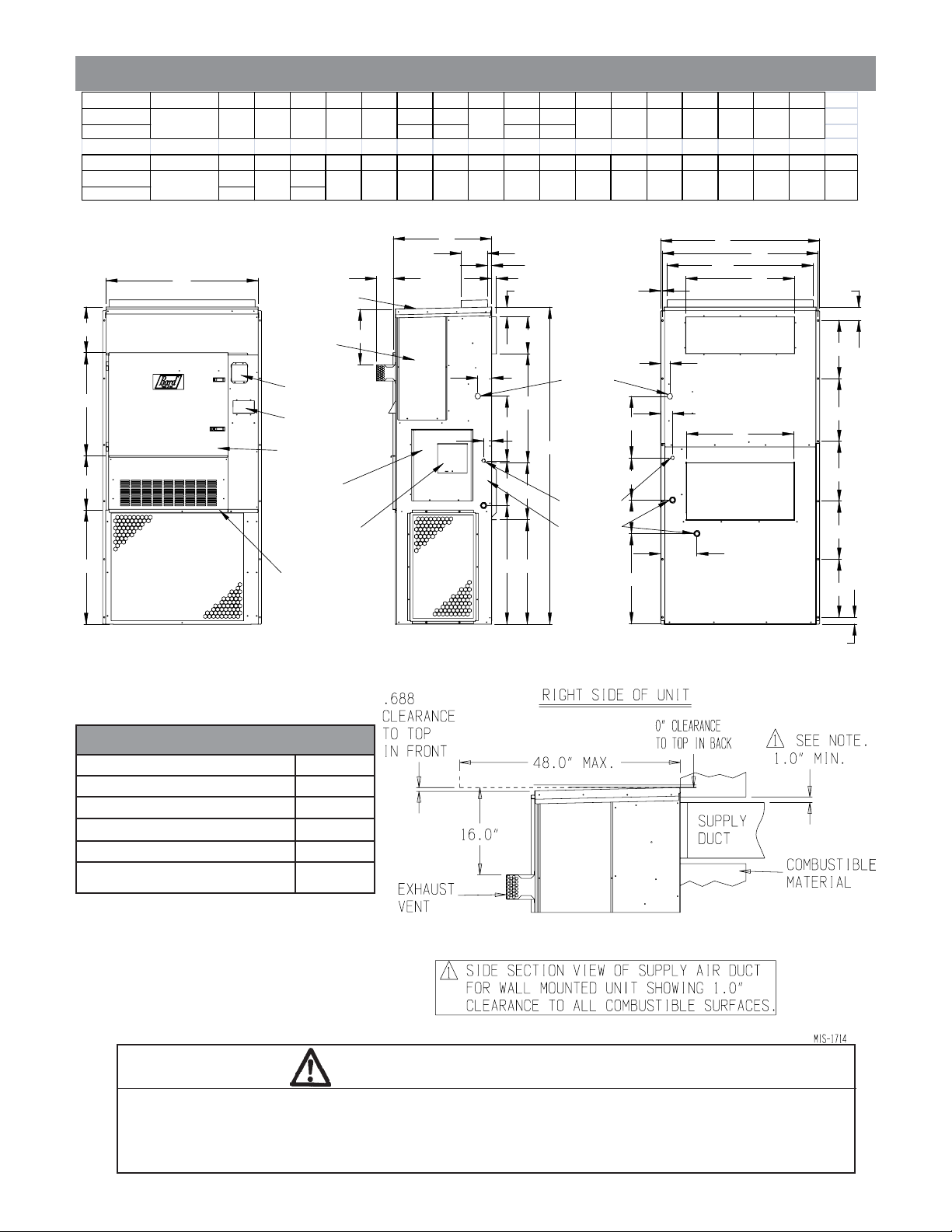
DIMENSIONS OF BASIC UNIT
UNIT A B C D E F G H I J K L M N O P Q R
WG3S1 31.63 87.5 33.38 28.75
G4S1/WG5S1 41.63 97.5
UNIT S T U V W X Y Z AA BB CC DD EE FF GG HH II JJ KK
WG3S1 3.75 24.9
9.88 29.88 15.88 27.25
16 - 6 HOLES
5
13.75
43.81
38.75
12.19 10 40.25
3.25
4.5
2.514.88 30 14.12 15.44 42.8815.31
1.257.25 1.132.253.88 42 17.34 8.44
0.44
2.75 12.75 28.25
3.75
JJ
KK
D
DD
W
4 DEG. PITCH IN TOP
VESTIBULE
DOOR
COMBUSTION
AIR EXHAUST
COMBUSTION
AIR INTAKE
SERVICE/FILTER
HINGED DOOR
F
G
CONDENSER
AIR OUTLET
FRONT
CONTROL
PANEL DOOR
CIRCUIT BREAKER/
DISCONNECT ACCESS
PANEL (LOCKABLE)
VENT OPTION
PANEL
P
N
CONDENSER
AIR INLET
RIGHT SIDE
FF
GG
HH
A
I
C
K
GAS
ENTRANCES
H
LOW VOLTAGE
ENTRANCES
HIGH VOLTAGE
ENTRANCES
U
M
Z
L
J
II
Q
X
AA
Y
V
FIGURE 1
COMBUSTIBLE CLEARANCE
SUPPLY OPENING
BB
RETURN OPENING
CC
EE
E
B
BACK
O
B
R
S
S
S
S
S
T
MIS-2328 D
teltuOresnednoC"02
poT1erugiFeeS
ecivreSrenruB"02
)lairetamgnirevocfoor
A minimum of one (1) inch clearance must be maintained between the supply air duct and combustible materials. This is
required for the first three (3) feet of ducting.
It is important to insure that the one (1) inch minimum spacing is maintained at all points.
Failure to do this could result in overheating the combustible material and may result in a fire causing damage, injury or death.
secnaraelCmumini
)slairetamelbitsubmocmorf(tcuDteltuO'3tsrif"1
)slairetamelbitsubmocmorf(lanimreTtneV"71
CroB,AssalCrodooW(esaBelbitsubmoC
"0
WARNING
Form No. S3396-1112
Supersedes S3396-212
Page 11 of 12

A
Air Conditioning Wall-Mount Model Nomenclature
WG 3 S 1 A X B B X X X X X
MODEL
NUMBER
COOLING
CAPACITY
3 - 3 Ton
4 - 4 Ton
5 - 5 Ton
STEP CAPACITY
SPECIALTY
PRODUCTS
(Non-Standard)
C= Canadian Approval
*125,000 BTU input model is not NOx certified.
REVISION
CODE
VOLTS & PHASE
A - 230/208-60-1
B - 230/208-60-3
C - 460-60-3
EMISSIONS
X - Standard
N - NOx Certified*
HEATING INPUT
A = 50,000
B = 75,000
C = 100,000
D = 125,000*
FILTER OPTIONS
X - 2-inch Pleated
W - 1-inch Washable
VENT OPTIONS
(See Table)
COLOR OPTIONS
X - Beige (Standard)
4 - Buckeye Gray
8 - Dark Bronze
COIL OPTIONS
X - Standard
1 - Phenolic Coated Evap.
2 - Phenolic Coated Cond.
3 - Phenolic Coating on
OUTLET OPTIONS
X - Front (Standard)
T - Top
snoitpOnoitalitneV
sledoM S5GW,S4GW,S3GW
1 .noitareporosserpmocerutarepmetwolrofrezimonocehtiwderiuqersilortnoctneibmawoL
2 .noitceleskcolblanimrethtiw)etar(sdeepstsuahxednaekatnifonoitcelestnednepednI
)eznorBkraD="8";yarGeyekcuB="4";egieB="X"(tinuhctamotdeificepsebtsumnoitporoloC
noitpircseD
)dradnatS(etalPffO-knalB B5-POBSGW
tsuahxE/wnruteRgnirpSgnitaludoM-rotalitneVlaicremmoC V5-PMVRCSGW
tsuahxE/wgnitaludoMylluF)lanretnI(rezimonocE 1 E5-MFIESGW
tsuahxE/wtloV032-rotalitneVyrevoceRygrenE 2 R-A5A-VRESGW
tsuahxE/wtloV064-rotalitneVyrevoceRygrenE 2 R-A5C-VRESGW
dellatsnIyrotcaF
.oNedoC
dellatsnIdleiF
.oNtraP
CONTROL
MODULES
(See Table)
both coils
dellatsnIdleiF-stiKnoisrevnoCteltuOylppuSpoT
SLEDOMHTIWDESU EGIEB-XROLOCTINU YARGEYEKCUB-4ROLOCTINU EZNORBKRAD-8ROLOCTINU
S5GW,S4GW,S3GWX-5GW-OST4-5GW-OST8-5GW-OST
seludoMlortnoCgninoitidnoCri
CPH 1 CPL 2 MCC 3 CAL 4 KS 5 edoCdellatsnIyrotcaF traPdellatsnIdleiF
DTSDTSDTSXA/N
DTSDTSDTS
DTSDTSDTS
DTSDTSDTS
DTSDTSDTS
STD = Standard equipment for these specified models.
1 HPC. High pressure control is auto reset. Always used with compressor control module (CCM) which is included. See note 3.
2 LPC. Low pressure control is auto reset. Always used with compressor control module (CCM) which is included. See note 3.
3 CCM. Compressor control module has adjustable 30-second to 5-minute delay-on-break timer. On initial power-up, or any time the power is interrupted, the delay-on-make will be
2-minutes plus 10% of the delay-on-break setting. There is no delay-on-make during routine operation of the unit. The module also provides the lockout feature (with 1
retry) for high and/or low-pressure controls, and a 2-minute timed bypass for low-pressure control.
4 LAC. Low ambient control permits cooling operation down to 0°F.
5 SK. Start capacitor and potential relay start kit can be used with all -A single phase models. Increases starting torque 9x. Not used for -B or -C three phase models.
)detoNsatpecxEsledoMllA(
H82-AMC
ylnOdellatsnIdleiF A-1S3GWrof411KS
ylnOdellatsnIdleiF A-1S4GWrof111KS
ylnOdellatsnIdleiF A-1S5GWrof511KS
seirosseccAdellatsnIdleiFlanoitpO
NOITPIRCSED REBMUNTRAP
)teeF000,01-0006(tiKhctiwSerusserPedutitlAhgiHsaGlarutaN 981-0268
.selbaTedutitlAdnaecifirOeeS.tnetnocUTBsaGdnaedutitlAnopUgnidnepeDderiuqeReByaMegnahCecifirOsaGlarutaN:etoN
)edutitlAteeF0006-0(tiKnoisrevnoCsaGenaporP 1-KCGW
)edutitlAteeF000,01-0006(tiKnoisrevnoCsaGenaporP 2-KCGW
)tnevlacitrevtoof5rofstrapllasedulcnI(tiKtneVlacitreV A5-KVV
A5-KVVrofnoitcesepiptnevlacitrevtoof1lanoitiddA 102-0268
A5-KVVrofnoitcesepiptnevlacitrevtoof2lanoitiddA 071-0268
A5-KVVrofnoitcesepiptnevlacitrevtoof3lanoitiddA 002-0268
A5-KVVrofnoitcesepiptnevlacitrevtoof5lanoitiddA 171-0268
Form No. S3396-1112
Supersedes S3396-212
Page 12 of 12
Bard Manufacturing Company, Inc.
Bryan, Ohio 43506
www.bardhvac.com
Due to our continuous product improvement policy,
all specifications subject to change without notice.
Before purchasing this appliance, read important energy cost
and efficiency information available from your retailer.
Form No.
S3396
November, 2012
Supersedes S3396-212
 Loading...