

Page 1
INSTALLATION INSTRUCTIONS
Partial Flow
Commercial Room Ventilator
24 Volt On/Off
with Spring Return and Exhaust
Model: CRV-F5
For Use with Bard Single Stage Wall Mount
Air Conditioner and Heat Pump Models:
W42AC, W48AC, W60AC, W72AC
W42HC, W48HC, W60HC
Bard Manufacturing Company, Inc.
Bryan, Ohio 43506
www.bardhvac.com
Manual: 2100-696A
Supersedes: 2100-696
Date: 9-16-19
Page 1 of 17
Page 2

CONTENTS
General Information ...............................................3
Commercial Room Ventilator Model Nomenclature ...
Unpacking .......................................................... 3
General ..............................................................3
Commercial Room Ventilator Features ....................3
Description .........................................................3
Models ...............................................................3
Installation of Field-Installed CRV-F5 .................4
Basic Installation .................................................4
Control System Notes ...........................................8
Blade Adjustment for Desired Ventilation Air ..........8
Sequence of Operation ....................................... 16
3
Figures
Figure 1 Disconnect Power ................................ 4
Figure 2 Remove Side Grilles ............................. 4
Figure 3 Remove Blower Door and Control Panel
Cover .................................................. 4
Figure 4 Remove Blank Off Plates (Both Sides) .... 5
Figure 5 Remove Exhaust Blank Off Plate ........... 5
Figure 6 Install Gasket ...................................... 5
Figure 7 Install Exhaust Blade Assembly ............. 5
Figure 8 Remove Air Filters and Low Voltage
Control Panel Cover .............................. 5
Figure 9 Connect 3000-1622 Wire Assembly ...... 6
Figure 10 Install Vent .......................................... 6
Figure 11 Control Plug Centered in Plug Access
Opening .............................................. 6
Figure 12 Connect CRV Power Plug to Control
Panel Plug........................................... 6
Figure 13 Remove Blade Shipping Screws ............. 6
Figure 14 Set Blade Stop to Adjust Fresh Air ......... 7
Figure 15 Install Intake Sealing Frame and
Lower Block Off Plates ......................... 7
Figure 16 Install Mist Filters ................................ 7
Figure 17 Install Bug Screen and Gaskets ............. 7
Figure 18 Programmable Thermostat Connections
for CRV with Air Conditioners .............. 11
Figure 19 Programmable Thermostat Connections
for CRV with Heat Pumps.................... 12
Figure 20 Non-Programmable Thermostat
Connections for CRV with
Air Conditioners ................................. 13
Figure 21 Non-Programmable Thermostat
Connections for CRV with Heat Pumps . 14
Figure 22 CRV-F* Wiring Diagram ....................... 15
Figure 23 Call for Ventilation With or WIthout
Compressor Operation ........................ 17
Figure 24 Call for Compressor or Fan Only with
Ventilation Off ................................... 17
Manual 2100-696A
Page 2 of 17
Graphs
Graph 1 W42AC CRV-F5 Ventilation Delivery ....... 9
Graph 2 W48AC CRV-F5 Ventilation Delivery ....... 9
Graph 3
Graph 4 W72AC CRV-F5 Ventilation Delivery ..... 10
Table
Table 1
(On/Off CRV)....................................... 16
W60AC
Unit Operation with M Ventilation Option
CRV-F5
Ventilation Delivery ...... 10
Page 3

GENERAL INFORMATION
Commercial Room Ventilator Model Nomenclature
CRV – F 5
Commercial Room Ventilator
Fixed 24 Volt On/Off
Chassis Size
5 – 4, 5 & 6 Ton Models
Unpacking
Upon receipt of the equipment be sure to compare the
model number found on the shipping label with the
accessory identification information on the ordering and
shipping document to verify that the correct accessory
has been shipped.
Inspect the carton housing of each ventilator as it is
received, and before signing the freight bill, verify that
all items have been received and that there is no visible
damage (check parts list below). Note any shortages or
damage on all copies of the freight bill. The receiving
party must contact the last carrier immediately,
preferably in writing, requesting inspection by the
carrier’s agent. Concealed damage not discovered until
after loading must be reported to the carrier within 15
days of its receipt.
General
The ventilator should only be installed by a trained
heating and air conditioning technician. These
instructions serve as a guide to the technician installing
the ventilator package. They are not intended as a stepby-step procedure with which the mechanically inclined
owner can install the package.
The ventilator housing is shipped in one carton which
contains the electrical harness, miscellaneous hardware
and installation instructions.
Ventilator kit includes:
(1) CRV-F5 ventilator
(2) 7003-084 mist filters
(1) 7003-083 exhaust bug screen
(2) 539-405 intake sealing frames
(1) 3000-1622 wire assembly
(2) 1913-002-0808 8-1/2" foam strips
(4) 1913-002-0708 7-1/2" foam strips
(1) 1913-013-2708 foam gasket
(2) 543-223 lower block off plates
(12) 1012-086 screws
(1) 539-414 exhaust damper assembly
(1) 2100-696A installation instructions
Commercial Room Ventilator Features
• Exhaust air damper – built in with positive closed
position. Provides exhaust air capability to prevent
pressurization of tight buildings.
• Actuator motor – 24 volt, power open, spring return
with built in torque limiting switch.
Description
The CRV-F5 ventilator is designed to be used with
the specific models with "letter" revision codes as
designated on the front page of this installation
instructions manual.
The ventilator is an electromechanical vent system
designed to provide fresh air to meet indoor air quality
standards.
Models
When installed in the models listed on the front page,
the CRV-F5 provides built-in exhaust provisions. When
the damper blade opens to bring fresh air in, the
damper also opens an exhaust relief. The exhaust air
will flow into the condenser section of the unit. The
condenser fan will help draw exhaust air out when it
is operating with compressor in cooling or heat pump
mode.
Manual 2100-696A
Page 3 of 17
Page 4
INSTALLATION OF FIELD-INSTALLED CRV-F5
Basic Installation
!
WARNING
Electrical shock hazard.
Disconnect remote electrical power supply
or supplies before servicing.
Failure to do so could result in electric
shock or death.
!
WARNING
Exposed moving parts.
Disconnect electrical power before
servicing.
Failure to do so could result in severe
injury or amputation.
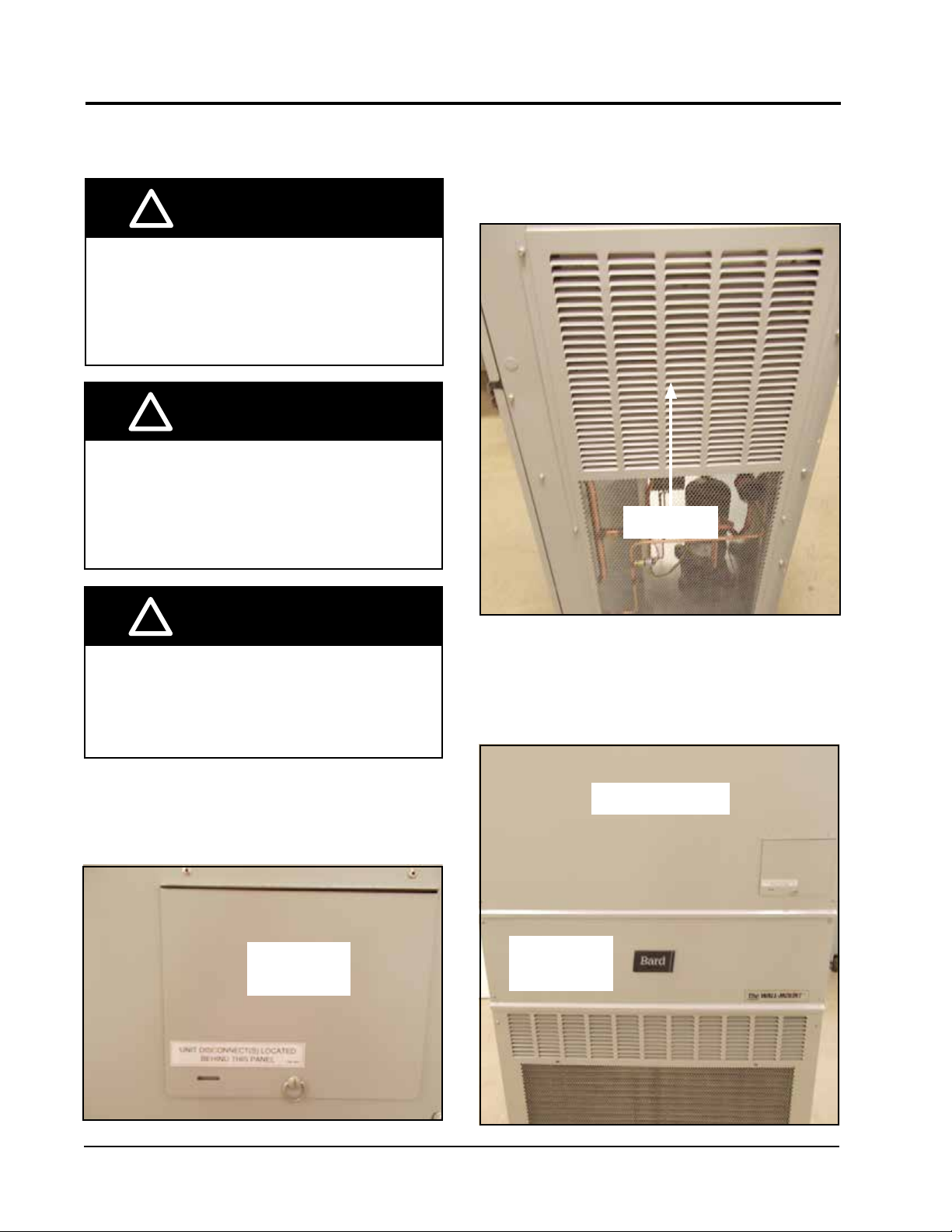
Remove both side grilles (see FIgure 2).
FIGURE 2
Remove Side Grilles
Side Grille
!
CAUTION
Cut hazard.
Wear gloves to avoid contact with sharp
edges.
Failure to do so could result in personal injury.
Disconnect all power to unit (see Figure 1).
FIGURE 1
Disconnect Power
Disconnect
Access Door
Remove upper blower door and outer control panel
cover (see Figure 3).
FIGURE 3
Remove Blower Door and Control Panel Cover
Upper Blower Door
Outer
Control Panel
Cover
Manual 2100-696A
Page 4 of 17
Page 5
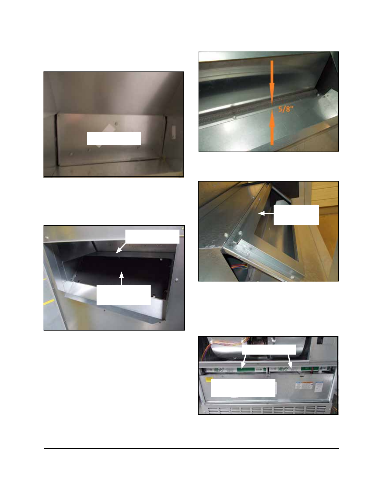
Remove blank off plates on both sides (behind side
grilles) and discard (see Figure 4).
FIGURE 4
Remove Blank Off Plates (Both Sides)
Blank Off Plate
Remove exhaust blank off plate through return or
through side intake openings (see Figure 5).
FIGURE 6
Install Gasket
FIGURE 7
Install Exhaust Blade Assembly
FIGURE 5
Remove Exhaust Blank Off Plate
Exhaust Partition
Exhaust Blank Off
Plate
Install 1913-013-2708 gasket 5/8" from bend as
shown in Figure 6. Then install exhaust blade assembly
using 10 screws (see Figure 7).
Exhaust Blade
Assembly
Remove both air filters and the low voltage inner control
panel cover (see Figure 8).
FIGURE 8
Remove Air Filters and
Low Voltage Inner Control Panel Cover
Air Filters (2)
Low Voltage Inner
Control Panel Cover
Manual 2100-696A
Page 5 of 17
Page 6
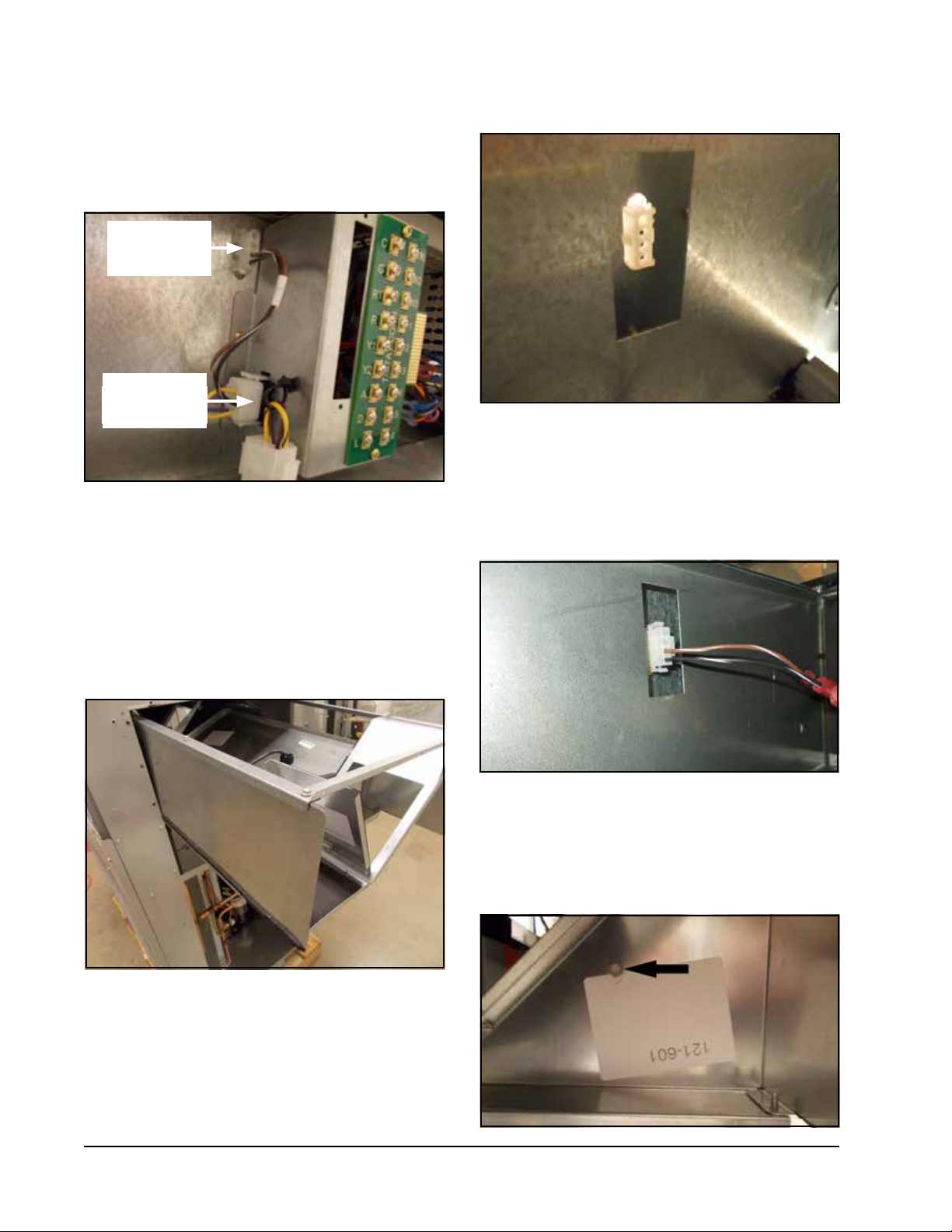
Connect 3000-1622 wire assembly (see Figure 9).
Snap the 4 pin connector into the opening next to the
low voltage box and plug the 12 pin male connector
into the female plug in the low voltage box.
FIGURE 9
Connect 3000-1622 Wire Assembly
4 Pin
Connector
12 Pin Male
Connector
FIGURE 11
Control Plug Centered in Plug Access Opening
From the front, through the filter opening, plug the CRV
power plug into the control panel plug (see Figure 12).
IMPORTANT: Sharp edges--PPE required.
Before installing vent, remove CRV from packaging
and verify there is no damage.
the side as shown in Figure 10. CRV can be installed
from either side.
Set CRV on the exhaust partition (see Figure 5 on page
5) and slide in until flush with the side of the wall
mount.
Install the vent from
FIGURE 10
Install Vent
FIGURE 12
Connect CRV Power Plug to Control Panel Plug
The CRV exhaust blade is fixed in the shipping position
by two (2) screws, one on each side (see Figure 13).
Remove screws to release the blade.
FIGURE 13
Remove Blade Shipping Screws
When the CRV is fully installed, the control plug should
be centered in the plug access opening on the front
panel of the CRV as shown in Figure 11.
Manual 2100-696A
Page 6 of 17
Page 7

Set blade stop (see Figure 14) using airflow charts
found on pages 9 and 10.
To adjust fresh air amount, loosen set screw two turns
on actuator stop. Slide stop to desired setting by
putting pressure toward the center drive shaft with
screwdriver while moving up and down. Use the marks
on the acuator to correlate with the airflow settings as
shown.
FIGURE 14
Set Blade Stop to Adjust Fresh Air Amount
Bend the two (2) sheet metal tabs in the condenser
partition up to hold the bottom of the mist eliminator
in place.
Install 7003-084 mist filters on both sides (see Figure
16). Then re-install the side grilles removed earlier.
FIGURE 16
Install Mist Filters
Mist Filter
Install the 539-405 intake sealing frame and the 543223 lower block off plates (both sides) as shown in
Figure 15. Install two (2) 1913-002-0708 7-1/2" foam
gaskets below the intake sealing frame (both sides).
FIGURE 15
Install Intake Sealing Frame and
Lower Block Off Plates
Intake Sealing
Frame
Lower Block
Off Plate
Remove the front lower (condenser) grille and bend the
two (2) sheet metal tabs in the condenser partition up
to hold the bottom of the bug screen in place. Install
two (2) 1913-002-0808 8-1/2" foam gaskets to sides
of cabinet (see Figure 17). Install the 7003-083
exhaust bug screen. Re-install grille.
FIGURE 17
Install Bug Screen and Gaskets
Foam Gaskets
Exhaust Bug
Screen
Install Gaskets Here
Restore power to unit. The "A" terminal can now be
energized to test blade operation. When blade testing is
complete, disconnect power.
Install both filters, then re-install the inner control panel
cover, outer control panel cover and upper blower door.
Restore power to unit.
Manual 2100-696A
Page 7 of 17
Page 8

Control System Notes
This ventilation package is capable of being set to
meet the current ASHRAE specifications for minimum
occupied airflow rates.
On/Off Operation
Energizing the A terminal in the low voltage connection
box during occupied conditions will drive the fresh
air damper to the fixed position selected as shown in
Figure 14 on page 7.
Blade Adjustment for Desired
Ventilator Air
The amount of ventilation air supplied by the
commercial room ventilator is dependant on four
factors.
1. Return air duct static pressure drop.
2. Supply air duct static pressure drop.
3. Indoor blower motor speed.
4. Damper blade open position setting.
Refer to the appropriate graph on pages 9 and 10 to
determine the blade setting necessary to achieve the
ventilation air required.
Manual 2100-696A
Page 8 of 17
Page 9

GRAPH 1
W42AC CRV-F5 Ventilation Delivery
GRAPH 2
W48AC CRV-F5 Ventilation Delivery
Manual 2100-696A
Page 9 of 17
Page 10

GRAPH 3
W60AC CRV-F5 Ventilation Delivery
GRAPH 4
W72AC CRV-F5 Ventilation Delivery
Manual 2100-696A
Page 10 of 17
Page 11

Completestat
Model #CS9B-THO or
Model #CS9BE-THO
SC
24V
FIGURE 18
Programmable Thermostat Connections for CRV with Air Conditioners
SC
SC
COM
G
Y1 Y2 O/B L DA GND
W2
W1/E
6
Thermostat
Bard #8403-060
Unit Low
Voltage
Term. Strip
1
12-Pin
Vent Plug
Factory installed jumper. Removejumper andconnect
1
to N.C fire alarm circuitif emergency shutdown required.
Wire not needed below15KW.2
Wire required for dehumidification modelsonly.
3
4
Do not connect "A" from thermostat ifoptional CO2controller is used
0-10 VDC modulating C02control signal formodulating ventilation
5
control (optional for ECON only- see vent instruction manuals)
6
9
23 5 7
ALL VENT OPTIONS PLUG IN HERE
If not equipped with a ventilation option to plug in, a jumper plug must be installed.
B/W1
119
2
W1/E
2
7
W2C GRT Y1 Y2
W3
A
LO/BY2Y1R GC W2
4
L DA 3
Change model configuration from heat pump to heat/cool.Must beconfigured to programmable
and fan set to be programmed fan for the "A"output to function duringscheduled occupied
6
periods. Must be configured formulti-stage for Y1output to beactive 1st stage cooling. For
dehumidification, must be configured for "No Economizer" for YO/D tobe active for humidity
control.
7
Install jumper for 1 stageelectric heaton unitswith less than15KW
Do not add these wiresif settingup for modulating control. See note 7.
8
Factory installed jumper. Removejumper to activateBalanced Climate
9
A 2-stage thermostat is recommended forBalanced Climatemode.
3
4
YO/D
5
Optional CO2 Controller
3
65421R
4
1012
Bard Part#8403-067
1
2
3
4
5
6
8
™
24VAC
CO2 OUT
TEMP-OUT
mode.
MIS-3974
A
Manual 2100-696A
Page 11 of 17
Page 12

Completestat
Model #CS9B-THO or
Model #CS9BE-THO
6
Thermostat
Bard #8403-060
SC
24V
FIGURE 19
Programmable Thermostat Connections for CRV with Heat Pumps
SC
SC
COM
G
Y1 Y2 O/B L DA GND
W2
W1/E
W1/E
3
2
4
YO/D
A
LO/BY2Y1R GC W2
Unit Low
Voltage
Term. Strip
1
12-Pin
Vent Plug
Factory installed jumper. Removejumper andconnect
1
to N.C fire alarm circuitif emergency shutdown required.
Wire not needed below 15KW.
2
Wire required for dehumidification modelsonly.
3
Do not connect "A" from thermostat ifoptional CO2controller is used
4
0-10 VDC modulating C02control signal formodulating ventilation
5
control (optional for ECON only- see vent instruction manuals)
6
8
23 5 7
ALL VENT OPTIONS PLUG IN HERE
If not equipped with a ventilation option to plug in, a jumper plug must be installed.
B/W1
119
2
4
3
W2C GRT Y1 Y2
L DA 3
W3
4
Ensure model configuration isheat pumpand notheat/cool. Must be configured to programmable
and fan set to be programmed fan for the "A"output to function during scheduled occupied
6
periods. Must be configured formulti-stage for Y1 output to beactive 1ststage cooling. For
dehumidification, must be configured for "No Economizer" for YO/D tobe active forhumidity
control.
7
Do not add these wiresif settingup for modulatingcontrol.
Factory installed jumper. Removejumper to activateBalanced Climate
8
A 2-stage thermostat is recommended forBalanced Climatemode.
5
Optional CO2 Controller
Bard Part#8403-067
1
24VAC
2
CO2 OUT
3
TEMP-OUT
65421R
1012
4
5
6
7
mode.
™
MIS-4063 A
Manual 2100-696A
Page 12 of 17
Page 13

8403-057
9
(TH311OD1040)
or T4 Pro 8403-089
8403-058
(TH522OD1151)
8403-059
(TH522OD1219/U)
or T6 Pro 8403-090
7
FIGURE 20
Non-Programmable Thermostat Connections for CRV with Air Conditioners
Units With Dehumidification
WCRc YR G
WRc CR G Y Y2
B
O
8
W2
6
35
8403-038
Mechanical Humidist at
8403-047
4
Electronic H umidistat
10
Unit Low
Voltage
Term. Strip
1
12-Pin
Vent Plug
Factory installed jumper. Remove jumper and connect
1
to N.C fire alarm circuit if emergency shutdown required.
2A
Wire not needed below 15KW.
Install Jumper for 1 stage electric heat on units with more
2B
than 10KW.
Wire required for dehumidification models only.
3
For vent operation, add jumper if optional CO2 controller is not used.
4
Vent will run while blower is energized.
For ECON & CRV-V an additional wire change is required
See install Manual.
5
Do not add these wires if setting up for modulating control. See note 7.
6
23 5 7
ALL VENT OPTIONS PLUG IN HERE
If not equipped with a ventilation option to plug in, a jumper plug must be installed.
119
B/W1
2A
3
6
2B
W3
W2C GRT Y1 Y2
L DA 3
4
4
0-10 VDC Modulating CO2 control signal for modulating ventilation control
6
(Optional for ECON Only) - See vent installation manual.
For 8403-058, change "system type", set up Function 1, From 5 (2 Heat/ 1 Cool heat Pump)
7
to 6 (2 Heat / 2 Cool Conventional). For 8403-059, No change required.
Jumper needs added.8
Thermostat will not work with units equipped with economizers.9
Factory installed jumper. Remove jumper to activate Balanced Climate™ Mode.
10
A 2-stage thermostat is recommended for Balanced Climate mode.
Optional CO2 Controller
Bard Part #8403-067
1
24VAC
2
3
CO2 OUT
4
65421R
5
TEMP-OUT
5
6
1012
MIS-3975 A
Manual 2100-696A
Page 13 of 17
Page 14

8403-057
9
(TH311OD1040)
or T4 Pro 8403-089
8403-058
(TH522OD1151)
8403-059
(TH522OD1219/U)
or T6 Pro 8403-090
7
Non-Programmable Thermostat Connections for CRV with Heat Pumps
R G Y Y2
C
FIGURE 21
Units With Dehumidification
8403-038
BCRc YR G
W
O
8
E
AUX
O/BRc
6
35
Mechanical Humidist at
8403-047
4
Electronic H umidistat
10
Unit Low
Voltage
Term. Strip
1
12-Pin
Vent Plug
Factory installed jumper. Remove jumper and connect
1
to N.C fire alarm circuit if emergency shutdown required.
Wire not needed below 15KW.
2
Wire required for dehumidification models only.
3
For vent operation, add jumper if optional CO2 controller is not used.
4
Vent will run while blower is energized.
For ECON & CRV-V, an additional wire change is required.
See install manual
5
Do not add these wires if setting up for modulating control. See note 6.
6
23 5 7
ALL VENT OPTIONS PLUG IN HERE
If not equipped with a ventilation option to plug in, a jumper plug must be installed.
119
B/W1
2
3
W3
W2C GRT Y1 Y2
L DA 3
6
4
4
0-10 VDC Modulating CO2 control signal for modulating ventilation control
6
(Optional for ECON Only) - See vent installation manual.
For 8403-058, change "system type", set up Function 1, From 5 (2 Heat/ 1 Cool heat Pump)
7
to 6 (2 Heat / 2 Cool Conventional). For 8403-059, No change required.
Jumper needs added.8
Thermostat will not work with units equipped with economizers.9
Factory installed jumper. Remove jumper to activate Balanced Climate™ Mode.
10
A 2-stage thermostat is recommended for Balanced Climate mode.
Optional CO2 Controller
Bard Part #8403-067
1
24VAC
2
3
CO2 OUT
4
65421R
5
TEMP-OUT
5
6
1012
MIS-4064 A
Manual 2100-696A
Page 14 of 17
Page 15

FIGURE 22
CRV-F* Wiring Diagram
FEMALE END
26
12 PIN
VENT PLUG
18
BLACK/WHITE
BLACK/WHITE
6
7
BLACK
BROWN/WHITE
PURPLE
9
3
1
17
5
Damper
Motor
16
21 3 4
2
8
17
YELLOW
4
MALE ENDMALE END
RED
BROWN/WHITE
4-Pin
Plug
10
1211
FEMALE END
18
ON/OFF CRV WIRING DIAGRAM
4056-244
Manual 2100-696A
Page 15 of 17
Page 16

Sequence of Operation
On/Off ventilation options energize when the “A” low
voltage strip terminal is energized signaling occupancy,
and de-energize when “A” terminal is no longer
receiving a 24VAC signal. The “G” low voltage strip
terminal is used to operate the indoor blower for unit
airflow.
The M On/Off CRV vent option is a damper blade
operated by a 24VAC motor that when energized opens
to a pre-adjusted setting. The airflow amount being
brought in will be dependent on the blower speed
during unit operation.
Unit Operation with M Ventilation Option (On/Off CRV)
TABLE 1
Unit
Operation
Occ.
Signal
G Y1 Y2 W1 W2 A D 1 2 3-4-5
Low Voltage 24VAC Speed Taps
Fan Speed
1
Comp.
Oper.
Damper
Fan Only Yes X X X Vent Off Open
Fan Only No X X Vent Off Closed
BC Cooling Ye s X X X X B Climate On Open
BC Cooling No X X X B Climate On Closed
Full Load Cool Ye s X X X X X X Lo/Med/Hi On Open
Full Load Cool No X X X X X Lo/Med/Hi On Closed
1st Stage Heat Yes X X X Lo/Med/Hi Off Open
1st Stage Heat No X X Lo/Med/Hi Off Closed
2nd Stage Heat Ye s X X X X Lo/Med/Hi Off Open
2nd Stage Heat No X X X Lo/Med/Hi Off Closed
Dehumidify
Dehumidify
2
2
Yes X X X X B Climate On Open
No X X X B Climate On Closed
BC and B Climate − Balanced Climate
¹ Fan speed is selectable through the blower speed control terminal block. LO (default), MED or HI speeds can be used.
2
Dehumidification operation is disabled when a call for heating or cooling occurs. Unit runs at Balanced Climate speed
during dehumidification operation.
Manual 2100-696A
Page 16 of 17
Page 17

FIGURE 23
Call for Ventilation With or Without Compressor Operation
FIGURE 24
Call for Compressor or Fan Only with Ventilation Off
Manual 2100-696A
Page 17 of 17
 Loading...