

Page 1

INSTALLATION INSTRUCTIONS
Partial Flow
Commercial Room Ventilator
24 Volt On/Off
with Spring Return and Exhaust
Models:
CRV-F2 CRV-F3
For Use with Bard Single Stage Wall Mount
Air Conditioner and Heat Pump Models:
CRV-F2
CRV-F3
: W18A/LB, W24A/LB, W18HB, W24HB
: W30A/LB, W36A/LB, W30HB, W36HB
Bard Manufacturing Company, Inc.
Bryan, Ohio 43506
www.bardhvac.com
Manual: 2100-691
Supersedes: NEW
Date: 3-1-19
Page 1 of 15
Page 2

CONTENTS
General Information ...............................................3
Commercial Room Ventilator Model Nomenclature ...
Unpacking .......................................................... 3
General ..............................................................3
Description .........................................................3
Application .........................................................3
Installation of Field-Installed CRV-F* .................4
Basic Installation .................................................4
Preparing Unit for CRV-F Installation ................. 4
Commercial Room Ventilator (CRV) No Hood
Installation .....................................................7
Blade Adjustment for Desired Ventilation Air ........11
3
Figures
Figure 1 Wall Mount Unit Access Panels ............. 4
Figure 2 Condenser Exhaust Plate with Screen..... 5
Figure 3 Filter Bracket and Filter Bracket
Fill Plate Installation ............................ 6
Figure 4 Extension Cable Installation .................. 7
Figure 5 Damper Assembly Installation ............... 8
Figure 6 Vent Door Assembly .............................. 8
Figure 7 Required Control Connections for CRV
with Air Conditioners ............................ 9
Figure 8 Required Control Connections for CRV
with Heat Pumps ............................... 10
Figure 9 Blade Adjustment For Desired
Ventilation Air .................................... 11
Figure 10 Call for Ventilation With or Without
Compressor Operation ........................ 14
Figure 11 Call for Compressor or Fan Only with
Ventilation Off ................................... 15
Graphs
Graph 1 W18 Ventilation Delivery ...................... 12
Graph 2 W24 Ventilation Delivery ...................... 12
Graph 3
Graph 4 W36 Ventilation Delivery ...................... 13
W30 Ventilation Delivery ....................... 13
CRV FEATURES
• One piece construction – easy to install with no
mechanical linkage adjustment required.
• Exhaust air damper – built in with positive closed
position. Provides exhaust air capability to prevent
pressurization of tight buildings.
• Actuator motor – 24 volt, power open, spring
return with built in torque limiting switch.
Manual 2100-691
Page 2 of 15
Page 3

GENERAL INFORMATION
Commercial Room Ventilator Model Nomenclature
CRV – F 2
COMMERCIAL ROOM VENTILATOR
FIXED (24V ON/OFF)
CHASSIS SIZE
2 – 1.5 & 2 Ton Models
3 – 2.5 & 3 Ton Models
Unpacking
Upon receipt of the equipment be sure to compare the
model number found on the shipping label with the
accessory identification information on the ordering and
shipping document to verify that the correct accessory
has been shipped.
Inspect the carton housing of each ventilator as it is
received, and before signing the freight bill, verify that
all items have been received and that there is no visible
damage. Note any shortages or damage on all copies
of the freight bill. The receiving party must contact
the last carrier immediately, preferably in writing,
requesting inspection by the carrier’s agent. Concealed
damage not discovered until after loading must be
reported to the carrier within 15 days of its receipt.
General
The ventilator should only be installed by a trained
heating and air conditioning technician. These
instructions serve as a guide to the technician installing
the ventilator package. They are not intended as a stepby-step procedure with which the mechanically inclined
owner can install the package.
The ventilator housing is shipped in one carton which
contains the electrical harness, miscellaneous hardware
and installation instructions.
Description
Commercial room ventilators CRV-F2 and CRV-F3 are
designed to be used with the specific models with
"letter" revision codes as designated on the front page
of this installation instructions manual.
The CRV-F ventilator is an electromechanical vent
system designed to provide fresh air to meet indoor air
quality standards.
Commercial room ventilators CRV-F2 and CRV-F3 are
internally mounted dampers with exhaust designed
to provide up to 50% fresh air. The damper blade
is powered by a 24 VAC motor with spring return on
power loss. The damper is powered open anytime A
is energized. Blade stop screws are located under the
fresh air blade and will provide 10 different airflow
settings.
When installed in the models listed on the front page,
the CRV-F provides built-in exhaust provisions. When
the damper blade opens to bring fresh air in, the
damper also opens an exhaust relief. The exhaust air
will flow into the condenser section of the unit. The
condenser fan will help draw exhaust air out when it
is operating with compressor in cooling or heat pump
mode.
Application
The amount of outside fresh air brought into the
structure is dependent on the supply and return duct
static pressure present in the duct system. Refer to
Graphs 1-4 on pages 12-13 for ventilation air that
will be supplied at different blade settings and duct
static pressures. For duct-free applications with return
air filter grilles and supply grilles, use 0.00 supply air
static pressure.
Manual 2100-691
Page 3 of 15
Page 4
INSTALLATION OF FIELD-INSTALLED CRV-F*
Basic Installation
!
WARNING
Electrical shock hazard.
Disconnect remote electrical power supply
or supplies before servicing.
Failure to do so could result in electric
shock or death.
Preparing Unit for CRV-F Installation
1. Disconnect power to unit.
2. Unpack the CRV-F assembly, which includes the
integral controls and electrical harness, body
panels, miscellaneous hardware and installation
instructions.
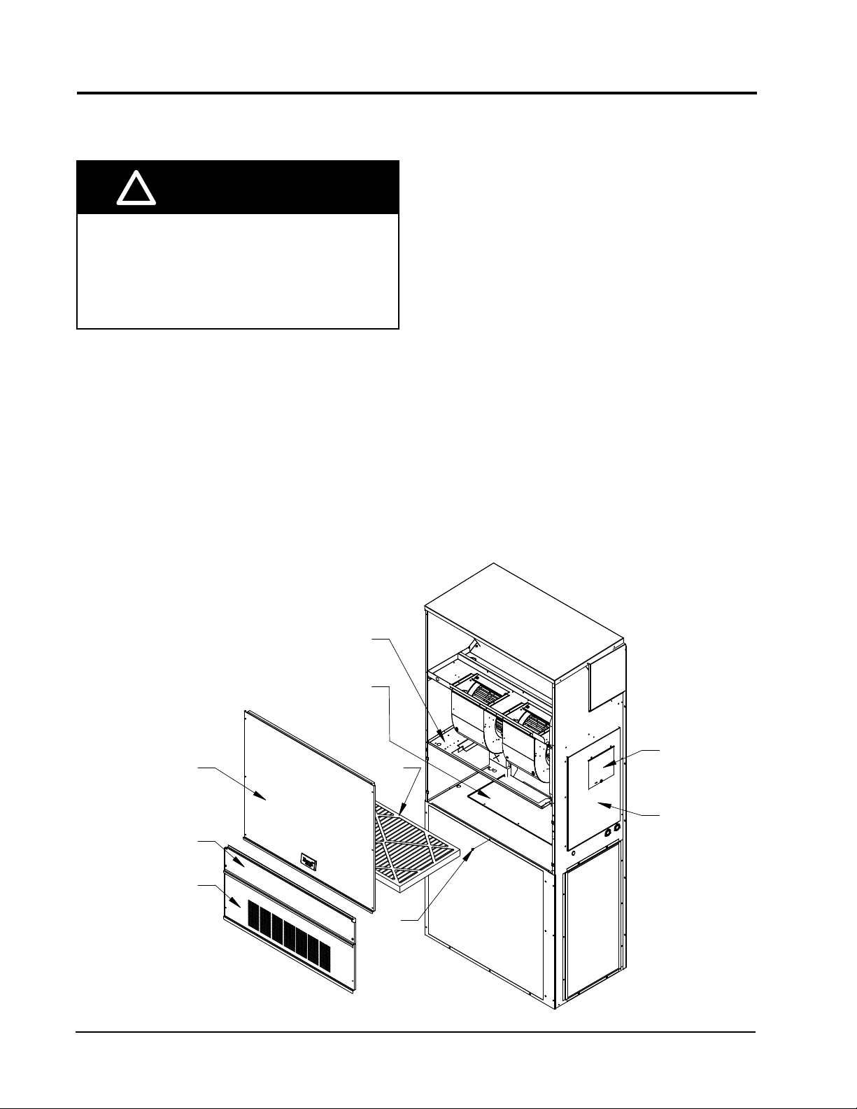
Wall Mount Unit Access Panels
3. From existing wall mount unit, remove and save (or
discard) as directed (see Figure 1):
• Blower access panel (save)
• Vent option panel (save)
• Filter access panel (save)
• Filter (save)
• Outer and inner control panel doors (save)
• Filter tray (discard, if applicable)
• Exhaust cover plate (discard)
4. Install new condenser exhaust plate with screen
over opening into condenser section (see Figure 2).
5. Remove filter brackets, if necessary. Two types
of filter brackets have been used with these wall
mount units. If the filter brackets are mounted
flat, they can be used with the commercial room
ventilator (CRV). If the brackets are set at a 30°
angle, they must be removed and discarded. The
circuit breaker offset plate must be loosened and
moved slightly to gain access to several of the
screws holding the filter brackets in place. Tighten
the screws holding control panel after the filter
brackets have been removed.
FIGURE 1
BLOWER ACCESS PANEL
FILTER ACCESS PANEL
VENT OPTION PANEL
FILTER TRAY
EXHAUST COVER PLATE
(THIS PLATE IS DISCARDED)
FILTER
SCREW
CIRCUIT BREAKER
ACCESS DOOR
CONTROL
PANEL DOOR
MIS-3987
Manual 2100-691
Page 4 of 15
Page 5
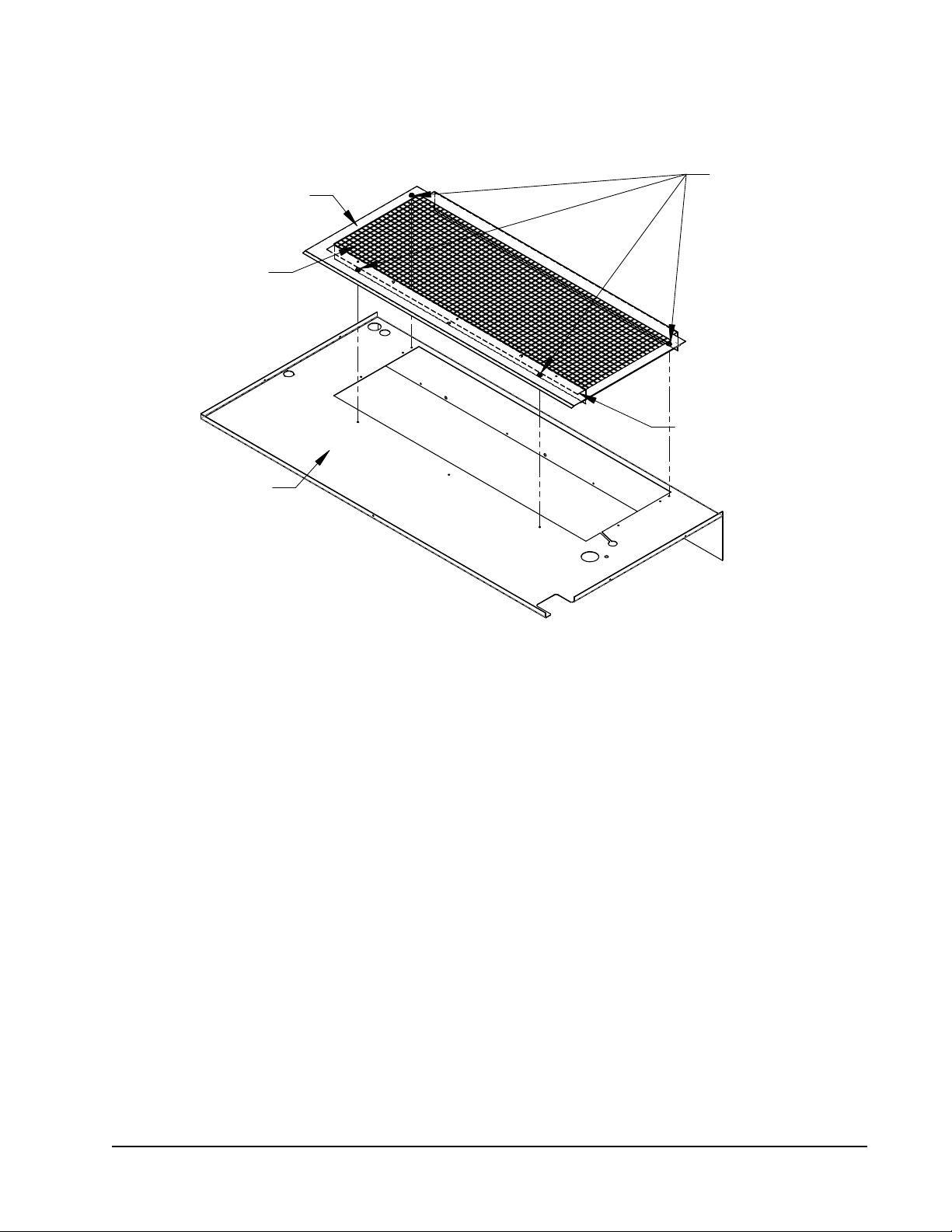
FIGURE 2
Condenser Exhaust Plate with Screen
Condenser Exhaust Plate with Screen
PARTITION COVER
INSTALL COVER PLATE
SCREEN MEDIA FACING
PARTITION
CONDENSER PARTITION
4 SCREWS
PLATE
PARTITION SUPPORT ANGLE
SHOWN FACING DOWN
(HIDDEN)
MIS-3633
If filter brackets were removed in Step 5, proceed
to Step 6. If the brackets were not removed,
proceed to Commercial Room Ventilator (CRV) No
Hood Installation on page 7.
6. Install filter bracket fill plate (if applicable) as
shown in Figure 3 on page 6.
7. Install provided filter brackets on CRV-F assembly
(see Figure 3).
Manual 2100-691
Page 5 of 15
Page 6

FIGURE 3
Filter Bracket and Filter Bracket Fill Plate Installation
INSTALL FILTER BRACKET
FILL PLATE WITH (2) SCREWS
(ONLY FOR 2-3 TON UNITS)
RIGHT HAND UNIT
LONG FILTER
BRACKET
Manual 2100-691
Page 6 of 15
(4) REGULAR SCREWS
(4) REGULAR SCREWS
SHORT FILTER
BRACKET
LEFT HAND UNIT
LONG FILTER
BRACKET
MIS-3988
Page 7

Commercial Room Ventilator (CRV) No Hood
Installation
1. Insert CRV into opening in the wall mount unit
between the filter rack and the condenser section,
being careful not to tear the unit insulation. Fully
seat CRV assembly to rear of the cavity. Slide the
CRV toward the control panel so that it lines up
with the return air opening in the rear of the wall
mount unit (see Figure 5 on page 8).
2. Insert and lock in the 12-pin plug end of the wire
assembly into the front side of the unit’s control
panel (see Figure 5).
Extension Cable Installation
3. Replace the air filters if they were removed (airflow
direction is up).
4. Put mist eliminator filter into place (as shown in
Figure 6 on page 8), then install the unit filter
door.
5. Make all the required thermostat connections per
the applicable connection diagram found on pages
9 or 10, and restore power to the unit.
6. Replace the lower vent option door with the four
(4) screws provided as shown in Figure 6.
FIGURE 4
NOTE: Incorporated with the CRV-F is one piece of 20˝ split
tubing. The tubing will cover the wire assembly routed to
the actuator. The tubing and wires will be routed under the
actuator assembly.
MIS-3989
FOR LEFT HAND MODELS, ROUTE ACTUATOR
WIRES TO THE LEFT SIDE
Manual 2100-691
Page 7 of 15
Page 8

FILTER/FILTER RACK
TOP OF OUTDOOR
COIL
FIGURE 5
Damper Assembly Installation
CONTROL PANEL
(RH SHOWN)
THE WIRE HARNESS
WILL PLUG INTO THE
FRONT SIDE OF THE
CONTROL PANEL.
POSITION SO THAT HOLE FROM LIP IS
WHEN INSTALLING CRV-F
CENTERED OVER HOLE IN CONDENSER
GRILLE TO INSERT A SELF DRILLING SCREW.
FILTER DOOR
ALUMINUM 8 MESH
SCREEN MATERIAL
FILTER
VENT DOOR
AFTER SLIDING THE VENT PACKAGE
INTO THE WALL MOUNT, SLIDE IT
TOWARD THE CONTROL PANEL SIDE
ALIGNING IT WITH THE RETURN AIR
OPENING IN THE REAR.
MIS-3999
FIGURE 6
Vent Door Assembly
INSERT (4) SCREWS
TO HOLD DOOR IN
PLACE.
Manual 2100-691
Page 8 of 15
MIS-3865
Page 9

Completestat
Model #CS9B-THO or
Model #CS9BE-THO
SC
24V
FIGURE 7
Required Control Connections for CRV with Air Conditioners
SC
SC
COM
G
Y1 Y2 O/B L DA GND
W2
W1/E
Thermostat
Bard #8403-060
Unit Low
Voltage
Term. Strip
1
Vent Plug
Factory installed jumper. Remove jumper and connect
1
to N.C fire alarm circuit if emergency shutdown required.
2 Not needed below 15KW.
Additional wire required for dehumidification models.
3
6 1012119 412-Pin
23 5 7
2
W1/E
LO/BY2Y1R GC W2
2
B/W1
W2C GRT Y1 Y2
CRV-F* PLUGS IN HERE
CRV-F PLUGS IN HERE
4
L/1 DA 4
W3/8
Demand ventilation control, which could include switched CO2 control, or secondary
motion activated switch.
3
YO/D
A
3
76532R
MIS-4000
Manual 2100-691
Page 9 of 15
Page 10

Completestat
Model #CS9B-THO or
Model #CS9BE-THO
SC
24V
SC
COM
FIGURE 8
Required Control Connections for CRV with Heat Pumps
SC
W1/E
G
Y1 Y2 O/B L DA GND
W2
Thermostat
Bard #8403-060
Unit Low
Voltage
Term. Strip
1
Vent Plug
Factory installed jumper. Remove jumper and connect
1
to N.C fire alarm circuit if emergency shutdown required.
2 Not needed below 15KW.
Additional wire required for dehumidification models.
3
6 1012119 412-Pin
23 5 7
2
W1/E
LO/BY2Y1R GC W2
2
B/W1
W2C GRT Y1 Y2
CRV-F* PLUGS IN HERE
CRV-F* PLUGS IN HERE
4
L/1 DA 4
W3/8 76532R
Demand ventilation control, which could include switched CO2 control, or secondary
motion activated switch.
3
YO/D
A
3
MIS-4001
Manual 2100-691
Page 10 of 15
Page 11

Blade Adjustment for Desired
Ventilator Air
The amount of ventilation air supplied by the
commercial room ventilator is dependant on four
factors.
1. Return air duct static pressure drop.
2. Supply air duct static pressure drop.
3. Indoor blower motor speed.
4. Damper blade open position setting.
Refer to the appropriate graph on the following pages
to determine the blade setting needed for required
airflow. Adjust blade stop screws accordingly (see
Figure 9).
Blade Adjustment for Desired Ventilation Air
FIGURE 9
BLADE STOP SCREW
BLADE STOPS
BLADE STOP SCREW
MIS-4002
Manual 2100-691
Page 11 of 15
Page 12

GRAPH 1
W18 Ventilation Delivery
GRAPH 2
W24 Ventilation Delivery
Manual 2100-691
Page 12 of 15
Page 13

GRAPH 3
W30 Ventilation Delivery
GRAPH 4
W36 Ventilation Delivery
Manual 2100-691
Page 13 of 15
Page 14

FIGURE 10
Call for Ventilation With or Without Compressor Operation
COOLING COIL
AIR FILTER
MIST
ELIMINATOR
OUTDOOR AIR
SUPPLY AIR
RETURN AIR
EXHAUST AIR
Manual 2100-691
Page 14 of 15
CONDENSER AIR
CONDENSER COIL
MIS-3866
Page 15

FIGURE 11
Call for Compressor or Fan Only with Ventilation Off
COOLING COIL
AIR FILTER
MIST
ELIMINATOR
OUTDOOR AIR
DAMPER BLADE
SUPPLY AIR
100% RETURN AIR
CONDENSER AIR
CONDENSER COIL
MIS-3867
Manual 2100-691
Page 15 of 15
 Loading...