

Page 1
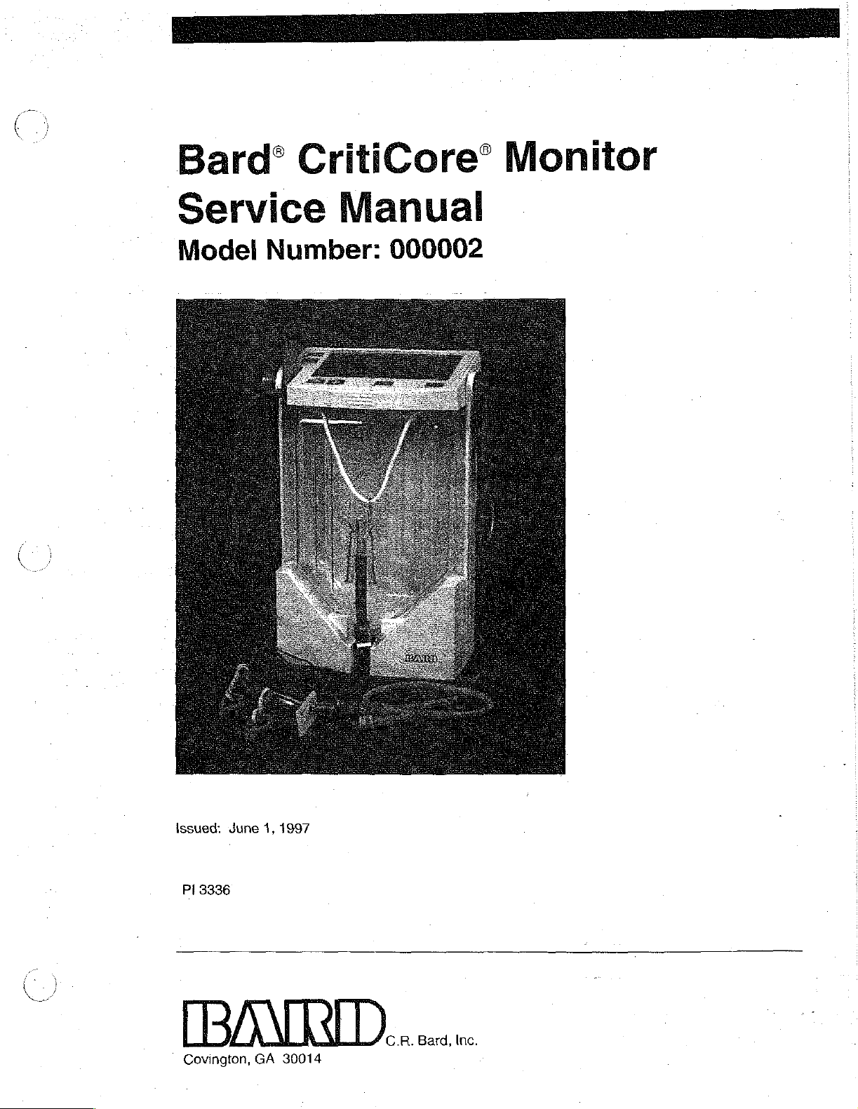
Bardº
CritiCore”
Monitor
Service
Model
Number:
Manual
000002
Issued:
Pl
3336
[BANA
Covington,
June
1,
GA
1997
30014
C.R.
Bard,
Inc.
Page 2
Copyright
©
1997
C.
R.
Bard,
Bard
and
CritiCore
or
an
affiliate.
This
document
information
to
which
dissemination,
this
document
disclosed
U.S.
Patent
to
others
Nos.
agrees
inc.
All
rights
are
registered
and
subject
C.R.
reproduction,
without
4,448,207,
it
shail
matter
Bard,
written
manufacture,
4,658,834.
reserved.
trademarks
enclosed
Inc.
not
be
consent
Printed
herein
retains
the
and
duplicated
of
Other
of
C.R.
are
exclusive
sale.
in
whole
C.R.
Bard,
patents
in
the
U.S.A.
Bard,
Inc.
proprietary
right
Any
party
or
in
Inc.
applied
of
accepting
part,
nor
for.
Notice
to
Service
Personnel
This
manual
Monitor.
Operators
Be
sure
before
Please
contraindications,
The
attempting
consult
Bard
credentials
equivalent
Caution:
Caution: - The
РР
will
help
Use
this
manual
Manual.
to
read
these
to
product
hazards,
CritiCore
of a Certified
only.
Federal
of
physician.
Bard
devices.
proper
to
properly
result
in
you
troubleshoot
in
conjunction
Manuais
disassemble
labels
warnings,
Monitor
should
Biomedical
(USA)
law
CritiCore
Do
not
attempt
personal
and
ground
damage
to
and
become
or
repair
and
inserts
cautions
be
Equipment
restricts
Monitor
to
work
both
your
the
Bard
and
service
with
the
familiar
the
Bard
for
any
and
serviced
this
by
device
contains
disassemble
station
grounding
body
and
CritiCore
the
Bard
Bard
CritiCore
with
their
CritiCore
indications,
directions
individuals
Technician
to
sale
by
static
sensitive
the
Monitor
apparatus.
your
work
Monitor.
CritiCore
Monitor
contents
Monitor.
for
use.
with
the
(CBET)
or
on
or
the
electronic
without
station
order
the
Failure
could
Page 3
Tabie
of
Contents
NOS
Product
Description
Communications
NY
2
Module.
Functional
Troubleshooting
Mechanical
Bezel
Bezel
Membrane
Display
Temperature
Liquid
Front
Attraction
Rear
Battery
Details
Fluid
Temperature
Microcontroller
Display
Keyboard
Power
Checkout...
Testing
Enclosure
Top
Switch..
PCB
Crystal
Enclosure
Plates
Enclosure
Assembly...
of
Electrical
Output
Electronics
Electronics
Management
information „13
and
Repair
Jack
Display
Electronics
Measurement
(LCD)
Assembly
and
Magnets
seen
Operation.
Details
..
Procedures.........
.
..
..
Electronics
mens
sie
…
20
20
Electronic
Power
Transducer
Phototransistor
Tilt
Temperature
Main
CritiCore
Main
Replacement
Product
Measurement
Instrument
index
CritiCore
Testing
Modules
Sensor
PCB.
Communications
PCB
Component
Specifications
Monitor
and
Calibration
.
..
Electronics
Parts
List.
Ranges
Specifications
Schematics.……....
Map
..
and
....
...
Module
......
Limits.
"eos
Procedures...
73
Bard
CritiCore
Monitor
Service
Manual
Page
1
Page 4

Page 5
Introduction
This
manual
satisfactory
qualified
particular,
personnel
microprocessor-controlled
conjunction
The
contents
1.
Product
specifications,
2.
Functional
*
operation
the
CBET
turther
the
testing.
Functional
returning
3.
Troubleshooting
predetermined
isolate
4.
Mechanical
to
(by
verify
general
5.
Electronic
the
test,
disassemble
either
correct
procedures
repair
is
operation
6.
Replacement
parts.
provides
operation
with
of
who
the
this
the
technical
of
the
are
Bard
CrítiCore
manual
service
Bard
CritiCore
familiar
with
Monitor
are
summarized
Description—Description
and
product
Checkout—Use
of
the
Monitor.
will
be
referred
After
Checkout
the
Bard
CritiCore
information.
If
the
to
repair
is
procedure
this
Monitor
the
necessary
made
Monitor
Information—For
failure,
use
this
guide
problem.
Testing
Bard
use,
Testing
to
made,
before
operation
test
and
and
or
the
and
and
use
the
returning
Parts
Kit
Repair
reassemble
CBET),
before
use
returning
Calibration
calibrate
Functional
the
Bard
List—Listing
the
information
Monitor.
It
electro-mechanical
patient
monitors.
Operator's
below.
ot
Bard
CritiCore
test
procedure
fails
(by
either
to
verify
for
general
monitors
to
identify
to
any
test
sections
Bard
correct
use.
with
the
Procedures—Use
the
Monitor.
the
Functional
the
Bard
Procedures—Use
electronics
Checkout
CritiCore
of
available
of
procedure
Monitor
necessary
is
intended
devices,
Use
this
Manual.
Monitor
verify
correct
within
of
this
or
the
CBET),
operation
an
obvious
necessary
these
After
repair
Checkout
CritiCore
these
the
Monitor.
to
for
general
Bard
replacement
to
maintain
for
use
and
manual
functions,
the
checkout,
manual
for
use
before
or
tests
to
procedures
is
made
procedure
Monitor
for
After
verify
correct
use.
by
in
in
to
Warranty
Repairs
Note:
The
Bard
and
electronic
operation
specified
7.
Product
instrument
8.
Schematics—Schematic
control
Bard
provides a 90-day
repairs
repair
facility.
may
forfeit
to
return
To
obtain
contact
Specifications—Measurement
specifications.
block
diagrams
on
products
If
there
any
warranty
the
Monitor
technical
Bard
Customer
CritiCore
components.
of
the
in
the
replacement
and
limited
under
warranty
is
any
provisions
to
its
original
support,
Service
Monitor
Monitor,
diagrams
timing
warranty
must
evidence
and
condition.
product
at
1-800-526-4455.
contains
To
use
only
parts
many
ensure
Bard
kit
ranges
for
the
CritiCore
charts.
on
each
Bard
be
performed
of
unauthorized
may
be
billed
information,
and
custom
safe
and
replacement
list.
and
limits
Monitor.
CritiCore
at a Bard
service
for
the
for
placing
mechanical
proper
parts
along
Includes
Monitor.
designated
the
customer
repairs
orders
as
with
・
All
required
Bard
CritiCore
Monitor
Service
Manual
Page
2
Page 6
Non-Warranty
Repairs
Monitors
no
longer
constraints:
1.
Only
components
the
repair.
2.
No
component
component
3.
Each
repaired
(see
page
Call
Bard
Customer
components
under
has
is
specified
Bard
7)
before
Service
necessary
warranty
included
been
in
CritiCore
it
is
may
in
the
removed
the
replacement
Monitor
returned
Department
to
complete a repair.
be
repaired
replacement
from
the
parts
Monitor
paris
for
general
passes
the
use.
(1-800-526-4455)
within
the
list
are
unless
list.
Functional
to
following
used
to
that
Checkout
order
make
Contacting
Bard
For
orders
and
1-800-526-4455
through
supply
*
*
«+
*
+
*
*
+
‚
If
Return
and
Customer
To
Friday.
the
Your
Name
Hospital
Address
Telephone
Unit
Model
Unit
serial
Description
Was
ihe
Paiient
you
are
advised
Authorization
address
return
the
following
Name
Monitor
status
of
Service
Bard
technical
between
When
calling
information:
Number
Number
number
of
the
reported
used
and
type
to
return
Label
the
repair
Representative.
CritiCore
support,
8:30AM
and
for
technical
problem
contact
on a patient
of
intervention
the
Monitor
or
detailed
facility,
will
Monitor
for
Bard
Customer
4:30PM
when
eastern
support,
the
problem
required
time,
please
(if
applicable).
to a Bard-designated
mailing
be
instructions,
supplied
to
you
service:
Service
Monday
be
prepared
occurred?
repair
with
the
by
your
at
facility,
name
Bard
to
a
1.
Remove
2.
Package
original
8.
Include a brief
number
Note:
3.
Ship
your
4.
If
requested,
before
’
Bard
CritiCore
and
dispose
the
Monitor
materials
of
the
person
Apply a label
shipping
the
Monitor
Bard
Customer
Bard
any
repairs
Monitor
of 6 D-cell
with
adequate
in
which
the
description
to
be
with
of
the
carton.
Transportation
Service
will
evaluate
are
made.
Service
Manual
batteries.
protection.
Monitor
the
contacted
return
was
problem
for
authorization
Prepaid
as
additional
to
Representative.
the
Monitor
if
available,
shipped.
well
as
the
information.
number
the
location
and provide
use
name
and
to
the
specified
an
estimate
the
phone
by
Page
3
Page 7
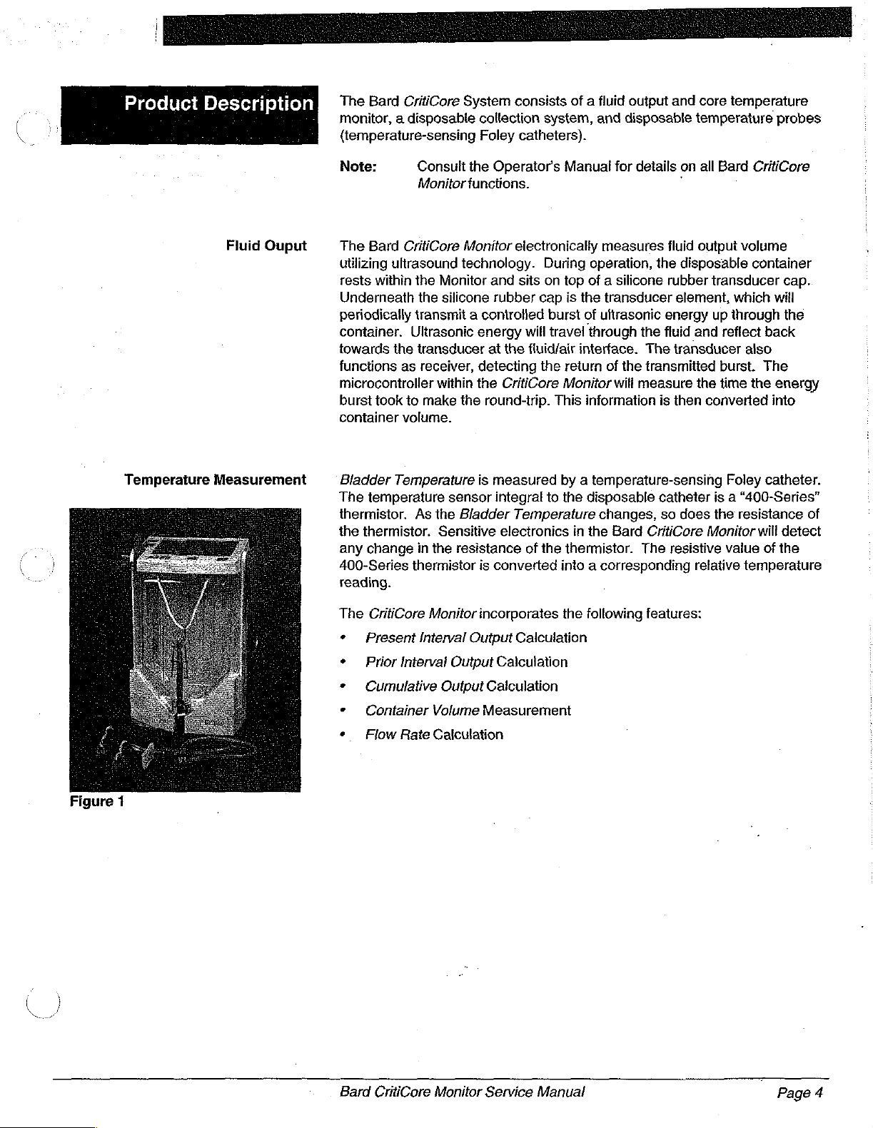
Product
Description
The
Bard
CritiCore
monitor, a disposable
System
(temperature-sensing
consists
collection
Foley
catheters).
of a fluid
system,
output
and
disposable
and
core
temperature
temperature
probes
Temperature
Fluid
Ouput
Measurement
Note:
Consult
Monitor
The
Bard
CritiCore
utilizing
rests
Underneath
periodically
container.
towards
functions
microcontroller
burst
container
Bladder
The
thermistor.
the
any
400-Series
ultrasound
within
the
the
transmit a controlled
Ultrasonic
the
transducer
as
receiver,
within
took
to
make
volume.
Temperature
temperature
As
the
thermistor.
change
in
the
thermistor
Monitor and
silicone
sensor
Sensitive
reading.
the
Operators
functions.
Monitor
electronically
technology.
sits
rubber
energy
at
the
detecting
the
CritiCore
the
round-trip.
is
measured
integral
Bladder
Temperature
electronics
resistance
is
converted
Manual
for
details
measures
During
on
cap
will
fluid/air
the
top
is
the
burst
of
travel
interface.
return
Monitor
This
information
operation,
of a silicone
transducer
ultrasonic
through
the
The
of
the
transmitted
will
measure
by a temperature-sensing
to
the
disposable
changes,
in
the
Bard
CritiCore
of
the
thermistor.
The
into a corresponding
on
all
-
fluid
output
the
disposable
rubber
element,
energy
fluid
and
transducer
the
is
then
converted
catheter
so
does
resistive
relative
Bard
CritiCore
volume
container
transducer
which
up
through
reflect
cap.
will
the
back
also
burst.
time
The
the
energy
into
Foley
catheter.
is a “400-Series”
the
resistance
Monitor
vaiue
will
detect
of
the
temperature
of
Figure
1
The
CritiCore
+ | Present
+ © Prior
+
»
*
Interval
Cumulative
Container
Flow
Rate
Monitor
Interval
incorporates
Output
Output
Output
Volume
Calculation
Calculation
Calculation
Calculation
Measurement
the
following
features:
Bard
CritiCore
Monitor
Service
Manual
Page
4
Page 8
i
/
i
fee
i
ο
i
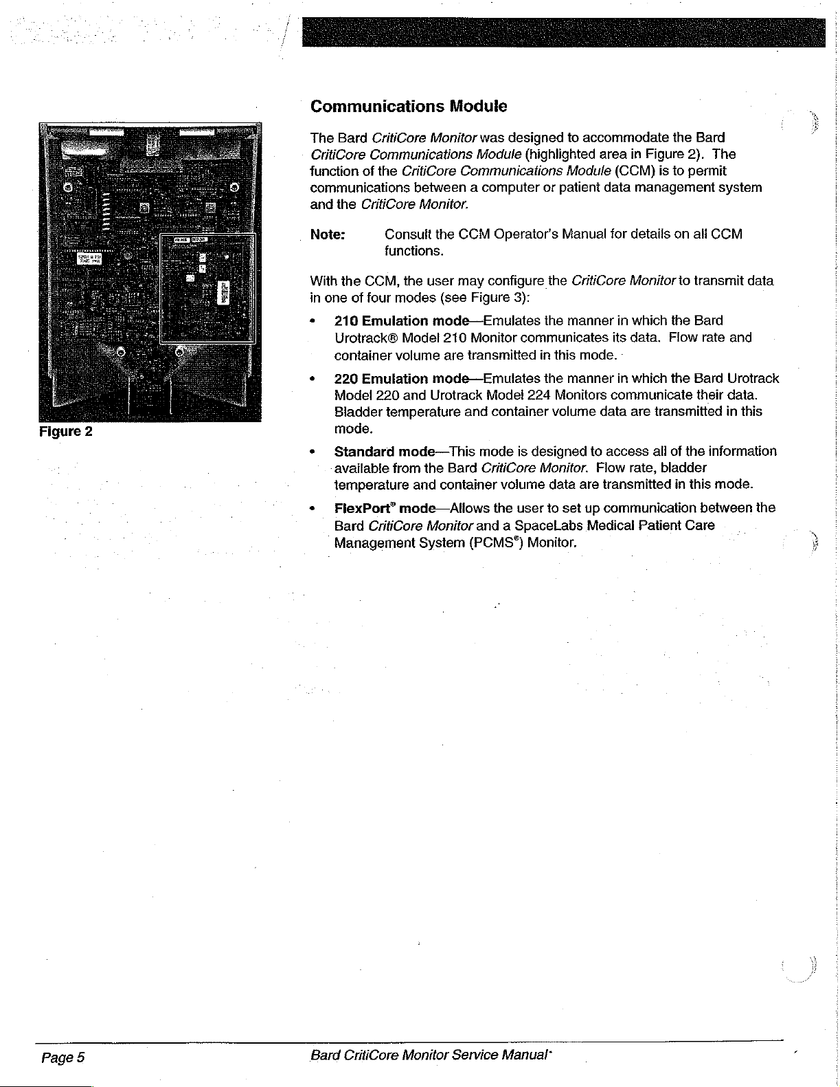
Communications
The
Bard
CritiCore
CritiCore
function
communications
and
Note:
With
in
one
*
+
Figure
2
*
Communications
of
the
the
CritiCore
Consult
functions.
the
CCM,
of
four
modes
210
Emulation
Urotrack®
container
220
Model
Bladder
mode.
Standard
-available
temperature
volume
Emulation
220
temperature
mode—This
from
CritiCore
the
Model
and
Module
Monitor
between a computer
Monitor.
the
user
mode—Emulates
mode—Emulates
Urotrack
the
and
was
designed
Module
Communications
CCM
Operator's
may
configure
(see
Figure
210
Monitor
are
transmitted
Model
and container
mode
Bard
CritiCore
container
volume
3):
communicates
is
to
accommodate
(highlighted
or
the
the
in
this
the
224
Monitors
volume
designed
Monitor.
data
area
Module
patient
Manual
CritiCore
manner
mode.
manner
data
to
Flow
are
transmitted
data
in
Figure
(CCM)
for
in
its
in
communicate
access
is
management
details
Monitor
which
the
data.
Flow
which
the
are
transmitted
all
of
rate,
bladder
the
Bard
2).
to
permit
on
all
to
transmit
Bard
Bard
their
the
in
this
The
system
CCM
data
rate
and
Urotrack
data.
in
this
information
mode.
+
FlexPort”
Bard
Management
mode—Allows
CritiCore
System
Monitor
the
user
to
and a SpaceLabs
(PCMS°)
Monitor.
set
up
communication
Medical
Patient
between
Care
the
у
Page
5
Bard
CritiCore
Monitor
Service
Manual
Page 9
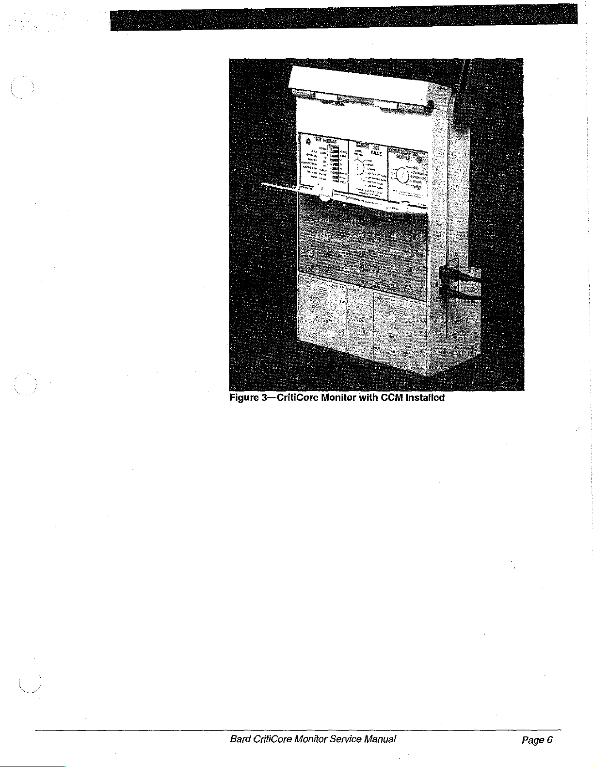
Figure
3—CritiCore
Monitor
with
CCM
Installed
Bard
CritiCore
Monitor
Service
Manual
Page
6
Page 10

Page 11
Functional
Chec
Product
t
Identification
Self
Test
The
Functional
Monitor
is
procedure
Monitor
purchased.
separately
Checkout
Functional
The
use
of
Modes
1.
2.
section
the
been
Hang
Bard
turned
the
surface.
3.
Clean
rubber
Checkout
functioning
is
available
The
(see
the
Replacement
procedure
Checkout
these
on
test
page
is
procedure
CritiCore
off
for
Monitor
both
the
cavity
transducer
procedure
properly
in
before
the
Operator's
Operator's
Parts
repeated
here
are the
modes
12.
Monitor
at
least
will
has
10
be
minutes
from a stable
that
holds
cap
located
at
is
designed
it
is
placed
Manual,
Manual
can
List
on
for
reference.
use
of
discussed
been
turned
before
levet
bracket
the
collection
the
bottom
to
verify
into
which
also
page
68).
In
the
T, - T,
in
the
Additional
on
recently,
initiating
or
set
container
of
the
that
the
service.
is
supplied
be
purchased
The
addition
Monitor
the
it
on a stable
and
cavity.
CritiCore
This
with
every
Functional
to
the
test
modes.
Testing
be
sure
it
self
test.
level
the
silicone
has
Note:
4.
Open
5.
Setthe
Set
Format
CLOCK
TEMPERATURE
BACKLIGHT
FLOW
FLOW
TEMP.
BEEPER
6.
Press
ON.
The
Monitor
should
automatically
Note:
Once
resemble
Use a soft
mild
detergent,
the
rear
control
toggle
RATE
RATE
ALARM
the
and
DISPLAY
ALARM
ON/OFF
will
take
about 4 seconds.
enter
If
the
Monitor
in
the top
the
self
test
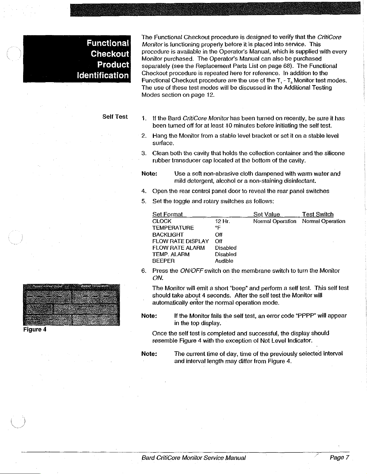
Figure 4 with
non-abrasive
alcohol
panel
rotary
switches
42
Hr.
°F
Of
Off
Disabled
Disabled
Audible
switch
on
emit a short
the
normal
fails
the
display.
is
completed
the
exception
cloth
dampened
or a non-staining
door
to
reveal
as
follows:
Set
Value
Normal
the
membrane
“beep”
and
perform a self
After
the
self
operation
self
and successful,
test,
of
mode.
an error
Not
with
disinfectant.
the
rear
Operation
switch
test
the
code
the
Level
warm
water
panel
switches
Test
Switch
Normal
to
turn
the
test.
This
Monitor
“PPPP”
display
will
should
Indicator.
and
Operation
Monitor
self
will
appear
test
Note:
Bard
The
current
and
interval
CritiCore
Monitor
time
of
day,
length
may
Service
Manual
time
of
differ
from
the
previously
Figure
4.
selected
”
interval
Раде?
Page 12
Check
Container
Status
1.
2.
3.
Lift
the
the
Monitors
Lower
within
Verify
and
“O
display
front
the
iid
ensuring
the
Monitor.
that
the
ML"
appears
assembly
cavity.
that
Check
Container
in
the
and
install
it
completely
status
Present
an
empty
`
closes
indicator
Interval
Output
disposable
and
on
display.
traps
the
display
container
the
into
container
is
not
lit,
Temperature
System
Clock
1.
Install a temperature-sensing
plug
into
the
temperature
Note:
2.
Verify
temperature
employing a temperature
02Ε.
3.
Remove
catheter
and
1.
Tur
HOUR
status
2.
Use
the
3.
Turn
MINUTE
indicator
A
precision
connected
instead
plug
that
the
the
and
that
the
the
SET
position.
indicators
the
Tl
correct
the
SET
position.
are
hour..
of a calibration
resistances.
Check
reading
temperature
verify
Check
VALUE
Verify
are
switches
VALUE
Verify
flashing.
jack
(0.1%
or
to a 3.6mm
Probe
appears
calibration
calibration
that
the
Bladder
Probe
status
rotary
that
the
flashing.
on
the
membrane
rotary
that
Foley
on
the
better)
mono
plug.
status
switch
switch
indicator
in
the
indicator
on
hour
on
the
minute
catheter
left
decade
mini-phone
See
Bladder
plug
plug
Temperature
segment,
or a temperature
side
of
box
page
disappears
Temperature
the
value
or
temperature-sensing
is
lit.
the
rear
control
PM/AM
switch
the
to
rear
control
segment
the
display
set
to
plug
59
for
should
window
set
the
and
assembly.
1954.70
may
be
table
of
and
that
display.
be
displays
panel
to
and
Set
system
panel
to
Set
Value
calibration
and
used
calibration
a
If
98.6°F
+
Foley
“--.-”
the
Value
clock
to
the
status
Page
8
Intervals
4.
Use
the T switches
clock
to
5.
Return
position
that
the
1.
Turn
the
that
the
flashing.
2.
Use
the
intervals: 5 MIN;
3.
Set
the
VALUE
Bard
CritiCore
the
correct
the
SET
VALUE
and
verify
Set
Value
SET
VALUE
interval
Tl
interval
rotary
segment,
switches
length
switch
Monitor
on
time
that
status
rotary
onthe
10
MIN,
to
to
Service
the
membrane
of
day.
rotary
the
correct
indicator
switch
HA/MIN
membrane
15
MIN,
the
preferred
the
NORMAL
Manual
switch
time
is
to
and
20
switch
to
to
the
NORMAL
appears
not
lit.
the
INTERVAL
Set
Value
switch
MIN;
30
to
MIN;
interval
OPERATION
set
the
on
the
status
display
1HR;
and
return
position.
minutes
OPERATION
display.
position.
indicators
the
2HR.
the
of
Verify
Verify
following
SET
the
are
Page 13
Patient
Interval
Figure
5
Data
Heset/Present
Output/Container
Volume
1.
Filla
so
Note:
tf
step
2.
Cut
urine
jnstall
tnser
tube
container
5.
Press
6.
Using
allow
Monitor.
7.
Wait
Monitor
approximately
8.
Press
approximately
seconds
9.
Press
heard.
10.
Press
Volume
the
disposable
that
it
is
higher
A
60cc
container
this
use
an
irrigation
2.
the
inlet
sample
ihe
modified
the plastic
on
the
filled
extending
the
ON/OFF
either
approximately
approximately
and
the
Container
after
and
hold
the
Container
display
Present
Interval
container
than
irrigation
or
two CritiCore
procedure.
only.
syringe
tubing
port
the
the
“100
“100
the
is
of a second
connector.
second
molded
container
from
switch
irrigation
100ML
10
surface
ML"
Volume
ml"
container
the
Patient
Volume
should
Output
with
water
the
Monitor.
syringe
These
used,
seconds
of
in
Verify
read
containers
proceed
disposable
empty
Control
into
the
the
Monitor
to
tum
syringe
of
water
after
the
water
the
Present
switch.
that
volume
Data
switch a second
within
display
(approximately
can
be
used
disposable
to
container
Fit
connector
soft
plastic
(see
the
Monitor
or a second
to
drain
the
water
is
steady.
Interval
The
display
the
container
switch
Reset
switch
3mi
of
the
should
to
fill
containers
should
step
Figure
is
read
be
5,
otherwise
container
into
the
at
the
tubing
5).
ON.
disposable
into
the
has
The
Output
should
volume
pressed.
until a short
time.
value
between
2100mi)
the
collection
can
dedicated
one
inch
Monitor.
end
of
on
the
container,
container
drained
Monitor
display.
read
disappears
“beep”
The
Container
noted
in
“0”
and
hang
be
used
for
test
continue
below
」
the
drain
second
in
the
into
the
should
Step 8 and
and
is
“3
read
30
ML”.
it
for
with
the
Flow
Rate
1.
Set
the
2.
Set
the
Note:
3.
Press
heard.
and
that
4.
Allow a small
The
seconds
steady.
Bard
CritiCore
FLOW
Interval
If
at
step
until
and
hold
Verify
dashes
Present
after
Monitor
RATE
length
least
15
3.
If
less
the
beginning
the
Patient
that
“0
“----”
amount
Interval
the
water
Service
toggle
to “1
minutes
than
ML”
appears
appear
of
water
Output
flow
switch
HR.”
remain
15
minutes
of
the
hour
Data
Reset
in
in
the
to
drain
should
has
stopped
Manual
to
the
ON
position.
in
the
current
remain
before
switch
the
Present
Flow
into
display a new
in
proceeding
until a short
Rate
display.
the
container
and
the
hour,
proceed
the
current
Interval
Output
reading
water
surface
hour,
with
“beep”
in
the
within
with
wait
step
3.
is
display
Monitor.
15
is
Page
9
Page 14
Not
Level
Full
Container
Indicator
Alarm
5.
Repeat
adding
After
from
Interval
With
~
Verify
3.
Return
indicator
1.
Open
to
2.
Verify
alarm
AUDIBLE
3.
Press
displayed
4.
Drain
Container
5.
Press
displayed
step 4 after
only a small
exactly
dashes
Output
the
that
the
the
fill
the
that
is
heard.
the
about
the.
each
amount
10
minutes
*---”
to a value
display.
Monitor
disappears.
drain
container
position.
Container
is
status
Container
is
ON,
the
Not
Monitor
clamp
the
Full
Note
greater
200ml
indicator
less
than
Level
to a level
in
Container
than
from
minute
the
tilt
the
status
on
the
the
Monitor
that
the
Volume
2000mi
the
is
Volume
2000ml
increment
of
water
current
that
is 6 times
Monitor.
indicator
position
upper
container
to
status
BEEPER
switch
and
Monitor
not
lit
and
switch
and
is
for
each
time.
Flow
Rate
the
becomes
and
verify
2050
mi
of
indicator
and
is
container
and
not
flashes
toggle switch
verify
flashing.
the
audible
verify
flashing.
10
consecutive
display
value
in
lit.
that
the
or
use
an
water.
that
the
and
verify
alarm
that
the
minutes,
should
the
Present
Not
change
Level
irrigation
and
an
audible
should
be
Container
that
the
stops
beeping.
Container
syringe
in
the
Volume
Full
Volume
High
Temperature
Alarm
Before
calibration
1.
2.
3.
Note:
4.
5.
performing
plugs
Set
the
BEEPER
Verify
that
Temperature
Turn
the
Verify
that
display.
be
lit.
Use
the
98.4°F.
Turn
the
position.
status
indicator
98.6+
0.2
this
procedure,
and
reset
TEMP
The 101.0°F
ALARM
toggle
SET
The
limit
removed
Tl
SET
Insert a 98.6°F
switch
the
bell
display.
VALUE
the
Set
High
has
not
switches
VALUE
is
°F,:and
icon
Value
Alarm
for
lit,
is
the
Monitor.
toggle switch
to
the
AUDIBLE
appears
rotary
switch
status
and
Check
will
appear
been
reset
an
extended
on
the
membrane
rotary
switch
calibration
the
value
flashing
and
remove
to
in
the
to
indicator
Probe
only
or
if
both
period
to
plug.
in
the
Bladder
the
audible
any
temperature
the
ENABLED
position.
upper
the
HIGH
and
status
if
the
temperature
battery
of
time.
switch
the
NORMAL
Verify
position
right
corer
TEMP.
101.0°F
to
Temperature
alarm
flashes
indicators
packs
set
the
OPERATION
that
the
is
beeping.
probes
'
of
the
ALARM
should
alarm
have
been
alarm
High
display
or
and
the
Bladder
position.
on
the
also
default
limit
to
Alarm
is
Page
10
Bard
CritiCore
Monitor
Service
Manual
Page 15

Low
Temperature
Alarm
6.
Press
value
Alarm
7.
Reset
temperature
Remove
~
2.
Turn
and
on
should
the
in
Silenced
the
the
verify
the
display.
also
Alarm
the
Bladder
High
Temperature
alarm
the
calibration
SET
VALUE
that
the
be
lit.
silence
Temperature
status
value.
Set
The
Low
switch
indicator
Alarm
plug
and
rotary
switch
Value
status
Alarm
to
verify
display
is
lit.
limit
reset
to
indicator
and
Check
that
continues
to
the
the
LOW
the
audible
the
preferred
Monitor.
TEMP.
and
50.0°F
Probe
status
alarm
to
flash
high
ALARM
(10.0°C)
indicators
stops,
and
the
position
the
flashes
Backlighting
Note:
3.
Use
99.0°F.
4.
Tum
position.
5.
insert a 98.6°F
indicator
6.
Reset
alarm
Place
Press
3.
Do
not
that
it
Note:
4.
If
the
toggle
The
50°F
has
not
for
an
extended
the
TL
switches
the
SET
VALUE
-
is
lit
and
the
Low
value.
the
BACKLIGHT
any
switch
touch
any
will
automatically
It
may
backlight
Monitor
switch
will
to
will
appear
been
reset
period
on
ihe
rotary
calibration
the
audible
Temperature
toggle
on
the
membrane
other
key.
shut
be
necessary
is
visible.
be
used
the
OFF
position
only
or
if
both
of
time.
membrane
switch
plug.
Verify
alarm
Alarm
switch
Verify
off
after
to
dim
in
well-lit
to
if
the
temperature
battery
switch
to
the
NORMAL
that
the
is
beeping.
limit
to
the
in
the
ON
switch.
that
the
display
30
seconds.
the
room
conditions
maximize
packs
have
to
set
Low
Alarm
preferred
position.
backlight
lighting
retum
battery
alarm
default
been
the
alarm
OPERATION
status
low
temperature
is
before
the
the
BACKLIGHT
life.
limit
removed
limit
to
on
and
Monitor
At
this
point
the
Completion
containers
required.
Bard
CritiCore
Functional
used
to
Monitor
hold
Checkout
fluid
so
Service
they
can
Manual
Procedure
be
used
is
complete.
to
check
Store
the
the
Monitor
Page
two
as
11
Page 16

Additional
Testing
Modes
There
are
two
CritiCore
additional
mode
is
discussed
page
When
enter
cycling
Once
switch
Liquid
LCD
When
enter
Interval
Bladder
Monitor.
information
T,
is
60)
and
the
rotary
into a display
through a sequence
in
T,
settings.
Crystal
Display
the
rotary
into a software
Output
Temperature
necessary,
Customer
Service
manufacturing
Located
used
only
in
the
Installing
should
TEST
testing
mode,
the
This
allows
Display
procedure
TEST
checksum
window,
have
the
Monitors
Representative
on
on
the
for
calibration
only
be
SWITCH
mode.
of
cycle
will
the
(LCD)
(on
page
SWITCH
the
software
window,
test
modes
the
rear
status
of
of
and
Calibrating
performed
is
rotated
This
decimal
continue
technician
are
functioning
30)
for
is
rotated
and
revision
checksum
the
software
serial
number
for
the
available
control
certain
the
functions.
temperature
the
by
qualified
to
the
mode
will
and
hexadecimal
regardless
to
verify
properly.
details
to
the
display
revision
available
correct
for
panel,
Main
T,
position,
cause
of
that
on
this
T,
position,
will
be
values.
further
T,
PCB
checkout
and
T,
can
Please
circuitry.
procedure
note
Calibration
personnel.
the
Monitor
the
display
numbers/letters.
any
toggle
all
segments
See
the
Testing
test
mode.
the
Monitor
mode.
In
the
displayed.
number
and
is
displayed.
contact
of
provide
that
(on
to
begin
or
rotary
of
the
the
Present
In
the
your
the
.
te.
will
will
If
Bard
Page
12
Bard
CritiCore
Monitor
Service
Manual
Page 17
Troubleshooting
Information
The
following
problems
troubleshooting
with
your
Bard
flowcharts
CritiCore
are
Monitor.
provided
to
help
diagnose
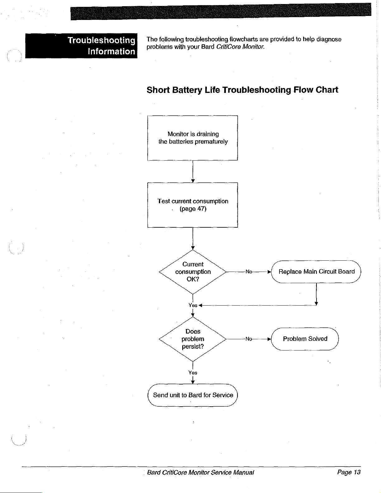
Short
Monitor
the
batteries
Test
Battery
is
draining
prematurely
Y
current
consumption
(page
47)
Life
Troubleshooting
Current
consumption
OK?
Flow
Chart
No
Replace
Main
Circuit
Board
Yes
+
unit
Does
problem
persist?
Yes
to
Bard
Monitor
for
Service
Service
No
Manual
Problem
Send
Bard
CritiCore
Solved
Page
13
Page 18

"Not
"Not
not
Level"
lit
when
Level"
lit
monitor
level.
when
not
level.
indicator
indicator
monitor
is
is
is
is
Tilt
Sensor
„|
Test
the
SENSPWR
(page
Troubleshooting
signal
47).
Flow
Chart
Verify
is
Test
that
within
the
(page
Does
check
the
monitor
6°
of
level.
Display
29)
LCD
out
OK?
LCD
Does
out
Yes
signal
OK?
SENSPWR
check
у
Test
the
Tilt
Sensor
(page
55).
Does
Tilt
Sensor
check
Yes
out
OK?
No:
Replace
Main
Circuit
Board.
Lightly
№-—+
tap
housing
sensor
on
to
3
Tilt
Sensor
loosen
ball.
Page
14
No
Replace
LCD.
ㆍ
Problem
solved.
Re-test
the
(page
Replace
Main
Circuit
Board.
No
Does
check
Problem
Bard
CritiCore
Monitor
Service
Manual
Tilt
Tilt
out
Yes
Sensor
5).
55)
Sensor
OK?
solved.
Page 19
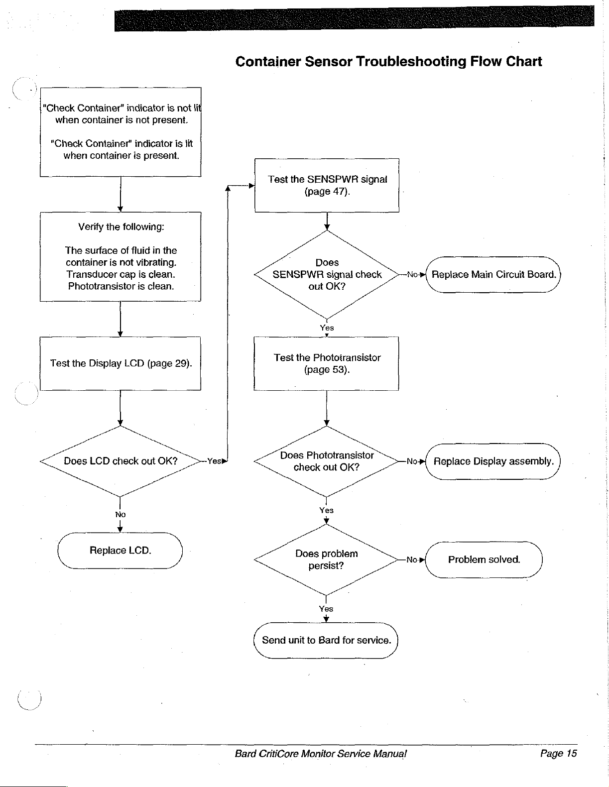
Container
Sensor
Troubleshooting
Flow
Chart
"Check
when
"Check
when
The
container
Transducer
Phototransistor
Test
the
Container"
container
Container"
container
y
Verify
the
following:
surface
is
of
not
cap
Display
indicator
is
not
present.
indicator
is
present.
fluid
in
the
vibrating.
is
clean.
is
clean.
LCD
(page
is
is
29).
not
lit
lit
Test
the
SENSPWR
(page
signal
47).
Does
SENSPWR
Test
the
signal
check
out
OK?
Yes
Phototransistor
(page
53).
No-
Replace
Main
Circuit
Board.
Does
LCD
check
No
Replace
out
LCD.
OK?
Does
Send
unit
Phototransistor
check
out
OK?
Yes
Does
problem
persist?
Yes
to
Bard
for
service.
No
No
Replace
Problem
Display
solved.
assembly.
Bard
CritiCore
Monitor
Service
Manual
Page
15
Page 20
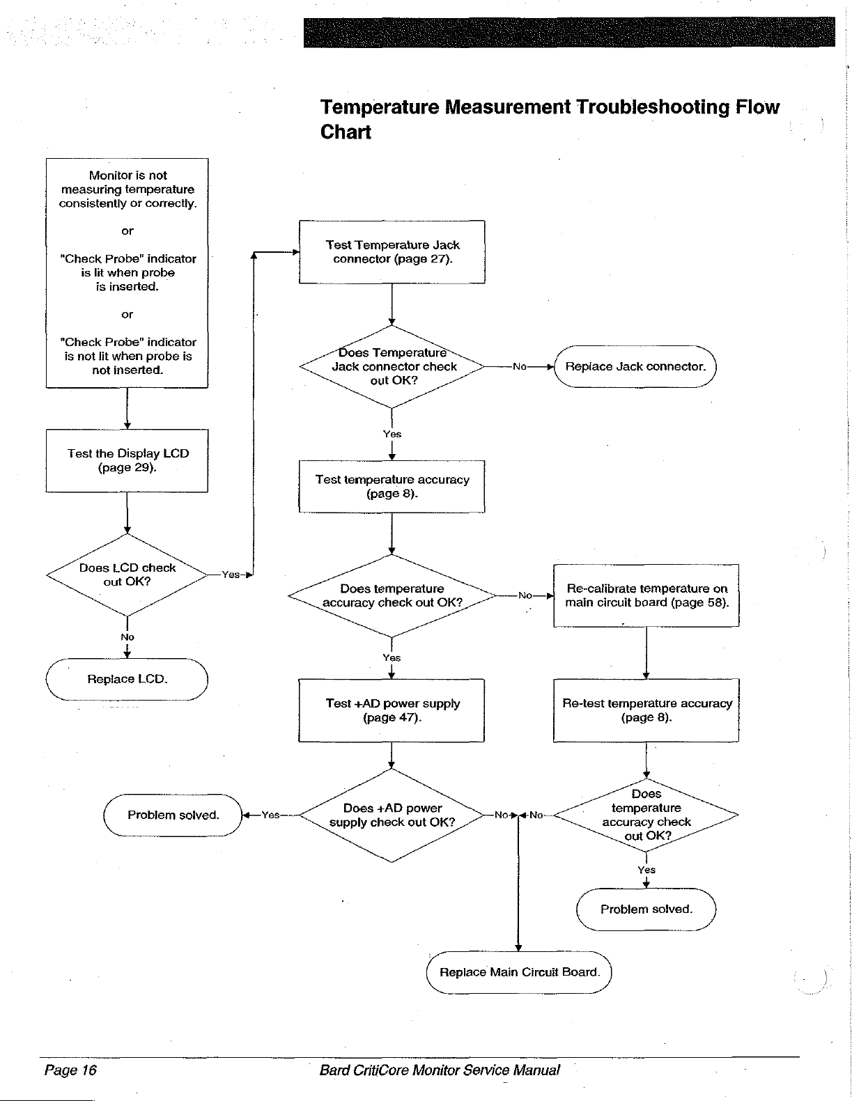
Monitor
measuring
consistently
"Check
is
or
Probe"
lit
when
is
inserted.
or
is
not
temperature
or
correctly.
indicator
probe
Temperature
Measurement
Troubleshooting
Flow
Chart
Test
|*
4
Temperature
connector
(page
Jack
27).
"Check
is
not
Test
Probe"
lit
when
not
inserted.
the
(page
indicator
probe
개
Display
29).
LCD
Does
LCD
|
Replace
out
check
OK?
No
LCD.
is
Does
Jack
Temperature
connector
out
OK?
Yes
check
No
Repiace
Jack
connector.
Test
temperature
(page
Does
accuracy
Test
temperature
+AD
(page
8).
check
Yes
+
power
47).
accuracy
out
OK?
supply
№—
Re-calibrate
main
circuit
Re-test
temperature
board (page
temperature
(page
8).
on
58).
accuracy
Page
16
Problem
solved.
Yes
Does
supply
Bard
+AD
power
check
out
CritiCore
OK?
Replace
Monitor
Main
Service
Circuit
Manual
Board.
Does
temperature
accuracy
out
Yes
Problem
check
OK?
solved.
Page 21

Volume
Measurement
Troubleshooting
Flow
Chart
Monitor
consistently
The
"Not
"Check
Transducer
_
Test
the
is
not
measuring
4
Verify
the
container
2000mi
Level"
Container"
holds
indicator
cap
Display
volume
or
correctly.
following:
less
than
of
fluid.
is
not
indicator
LCD
is
clean.
(page
is
lit.
not
29).
lit.
4
Test
the
STRTXM
signal
(page
Does
Test
STRTXM
check
Yes
the
Transducer
(page
out
y
charge
51).
signa
OK?
signal
50).
N
o:
Replace
Board.
Main
Circuit
Does
LCD
check
out
No
Replace
LCD.
OK?
?
signal
Does
Send
unit
Does
check
problem
to
Transducer
out
OK?
Yes
persist?
Yes
Bard
for
service.
No
z
ο
Replace
Problem
Transducer.
solved.
Bard
CritiCore
Monitor
Service
Manual
Page
17
Page 22
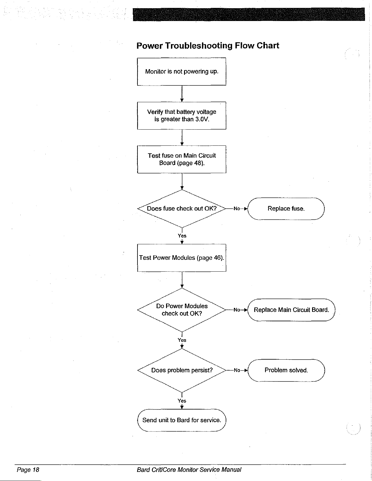
Power
==
Troubleshooting
Flow
Chart
Monitor
Verify
is
greater
Test
Board
Does
is
that
fuse
fuse
not
powering
г
battery
than
r
on
Main
(page
check
Yes
y
up.
voltage
3.0V.
Circuit
48).
out
OK?
No:
Replace
fuse.
Test
Power
Does
Send
Do
check
unit
Modules
Power
out
Yes
problem
Yes
to
Bard
(page
Modules
OK?
persist?
for
service.
46).
No
No
Replace
Problem
Main
Circuit
solved.
Board.
Page
18
Bard
CritiCore
Monitor
Service
Manual
Page 23
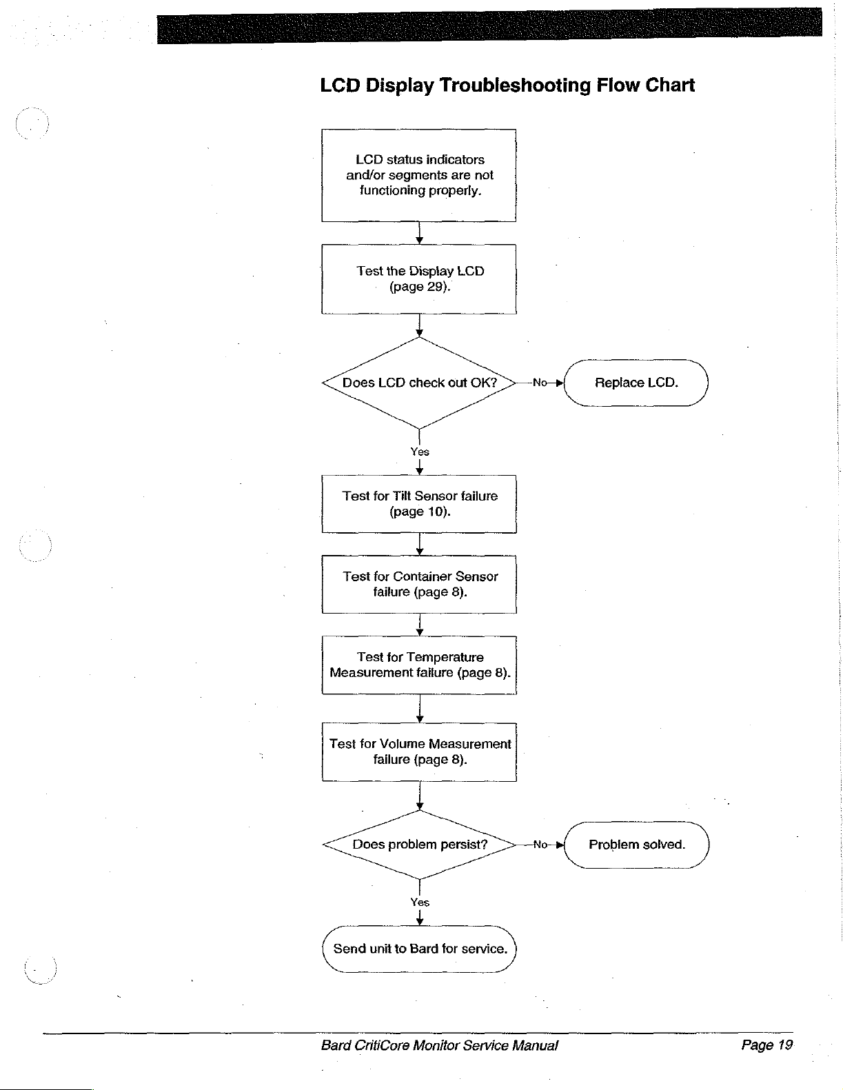
LCD
Display
LCD
status
and/or
segments
functioning
Test
the
(page
Troubleshooting
indicators
are
not
properly.
4
Display
LCD
29).
Flow
Chart
Does
LCD
Test
for
Tilt
(page
Test
for
Container
failure
o
Test
for
Measurement
Test
for
Volume
failure
check
out
Yes
Sensor
failure
10).
!
Sensor
(page
8).
Temperature
failure
(page
4
Measurement
(page
8).
OK?
No
8).
“|
Replace
LCD.
Does
problem
Send
unit
to
Bard
CritiCore
persist?
Yes
Bard
for
Monitor
service.
Service
No
Manual
Problem
solved.
Page
19
Page 24

Page 25

Mechanical
-and
A
Testing
Repair
The
following
assembly
CritiCore
sections
procedures
Monitor.
outline
for
the
the
appropriate
individual
testing,
mechanical
disassembly
components
of
and
the
re-
Bard
Figure
6
Testing
the
Bezel
Enclosure
Bezel
The
from
attached
pins.
the
attraction
container.
seated
signal
Visually
broken
be
must
40)
1.
2.
3.
Enclosure
bezel
enclosure
impact
attraction
replaced.
be
for
Place a disposable
_Lift
onto
and
ff
material
assembly
insert,
to
The
magnets
is
The
on
the
loss
when
inspect
or
cracked,
replaced.
magnet
the
the
rest
the
bezel
remove
and
the
bezel
plates
necessary
force
transducer
If
one
replacement
display
container
on
enclosure
inside
may
Enclosure procedure
must
be
replaced.
insert
and
hinge
isopropyl
alcohol.
(Figure
6)
contamination
top
and
inserted
which
on
to
the
are
apply
and
container
cap.
the
container
the
bezel
enclosure
it
may
allow
or
both
of
See
the
Attraction
procedure.
container
assembly
cap.
The
the
container
hinge
the
hinge
be
hindered.
the
hinge
pins
(below).
lf
foreign
pin
by
using a non
protects.
by
foreign matter.
is
hinged
to
affixed
attached
pressure
cap
This
in
turn
holds
little
for
damage.
fluid
to
enter
the
magnets
Plates
into
the
up
approximately
dispiay
cap.
pin
insert
pin/insert
junction,
To inspect
as
described
If
cracks
matter
abrasive
the
underside
the
front
to
the
bezel
to
the
front
to
ihe
top
ensures
allows
or
no
fluid.
into
are
missing
and
Monitor.
1/2
assembly
is
cracked,
for
cracks
in
are
found,
is
the
cause,
of
The
enclosure
enclosure
enclosure.
of
the
that
for
minimal
if
the
the
display
Magnets
inch
should
or
the
movement
the
Removing
the
clean
cloth
dampened
the
display
bezel
is
by
disposable
the
container
bezel
enclosure
PCB
or
damaged,
section
and
allow
drop
if
there
inside
the
bezel
out
PCB
directly
the
hinge
are
drawn
The
force
is
firmly
transducer
is
and
should
they
(on
page
it
to
drop
unhindered
is
foreign
of
the
display
hinge
pin
the
Bezel
enclosure
the
plastic
with
70%
to
of
Removing
the
Bezel
Enclosure
个
Equipment
*
No. 2 Phillips
e | Needle
Caution:
Required
screwdriver
nose
pliers
The
Bard
static
sensitive
internal
Discharge)
your
components
body
CritiCore
electronic
handling
and
your
Monitor
devices.
without
equipment.
work
station
main
proper
could
and
display
Do
not
ESD
Failure
result
PCB’s
contain
attempt
to
repair
(Electro-Static
to
properly
in
ground
damage
to
any
both
the
Monitor.
Bard
CritiCore
Monitor
Service
Manual
Page
20
Page 26

Page 27

Figure
‘Figure
8
9
Note:
Procedure
1.
Ensure
battery
2.
Place
3.
Remove
Monitor
it.
snap
remove
position
Using a needle-nose
After
Figure
6.
Open
the
puit
7.
Remove
Figures 9 and
door.
8.
Pull
the
the
set
9.
Pull
12),
display
Review
(see
you
that
packs.
the
the
enclosure.
The
snap
ring
it.
by
removing
8.
the
TEST
gently
the
straight
front
of
blank
aside
the
out
on
Disconnect
assembly
the
contents
Replacement
may
need
the
Monitor
Monitor
must
İf
rear
SWITCH
to
the
insert
the
face
hinge
pins
Each
ring
must
be
oriented
the
snap
using a small
both
snap
control
rotary
remove
four
(4)
10
(arrows
up
on
the
Monitor.
in
place
blank
plastic
ejector
the
is
totally
of
Parts
to
keep/discard
is
turned
down
on a soft
which
hinge
be
removed
properly,
ring
is
not
flathead
pliers,
the
6-32x3/8”
display
remove
rings,
pane!
door.
knobs
rotary
indicate
rear
enclosure
The
while
insert.
latches
cable
detached
arrow
the
bezel
List
on
during
off.
Remove
surface.
connect
knobs.
Phillips
removing
on
the
pin
has
in
order
as
properly
screwdriver.
both
pull
out
Ensure
are
set
pan-head
screw
(see
in
Figure
the
display
from
from
enclosure
page
66),
to
disassembly.
the
battery
display
an
e-style
illustrated
oriented,
snap
both
that
to
NORMAL
locations).
Figure
the
the
the
assembly
snap
to
pull
out
in
rings.
hinge
both
screws
11)
11.
illustrates
rear
enclosure.
cable
main
PCB.
Monitor.
replacement
confirm
Figure 7 in
rotate
pins
the
OPERATION,
Close
to
connector
which
doors
to
ring
mounted
the
hinge
it
into
as
illustrated
SET
VALUE
as
illustrated
the
separate
how
Remove
(see
At
this
parts
parts
and
the
pin.
order
correct
then
rear
panel
it
from
to
hold
Figure
point
kit
on
The
to
in
>
and
in
and
°
the
Fi
본
0
igure
Installing
the
Bezel
Enclosure
7
10.
Place
switch
11.
Separate
the
four
Equipment
e
No. 2 Phillips
+
Needle
Caution:
Bard
CritiCore
the
display
is
face
down.
the
bezel
(4)
6-32x1/4”
Required
screwdriver
nose
pliers
The
Bard
static
sensitive
internal
Discharge)
your
body
Monitor.
Monitor
assembly
enclosure
Phillips
CritiCore
electronic
components
handling
and
your
Service
on a soft
from
the
pan-head
Monitor
equipment.
work
Manual
main
devices.
without
station
surface.so
bezel
top
screws.
and
display
Do
not
proper
ESD
Failure
could
result
that
the
membrane
assembly
attempt
(Electro-Static
to
properly
PCB's
in
damage
by
contain
to
repair
ground
removing
any
both
to
the
Page
21
Page 28

Procedure
1.
2.
Figure
11
3.
4.
5.
6.
7.
8.
Install
the
four
(4)
6-32x1/4”
Reconnect
Ensure
are
Place
plastic
the
screws
Ensure
for
Insert
Insert
Stand
SET
on
when
Perform
alt
that
firmly
the
blank
rear
enclosure
(see
that
the
hinge
the
and
the
VALUE
the
two
they
the
display
bezel
enclosure
Phillips
the
display
the
cable has
closed.
rear
enclosure
insert
is
by
Figures 9 and
the
display
pins
are
two
hinge
connect
Monitor
knobs
were
and
the
up,
and
TEST
are
removed.
Functional
general
to
pan-head
cable
been
onto
held
into
installing
10).
assembly
clear.
pins
(see
battery
open
the
SWITCH
oriented
Checkout
Monitor
the
bezel
screws.
connector
fully
inserted
the
front
position
the
four
is
correctly
Figure
8),
packs
and
rear
control
rotary
in
the
same
procedure
functions
top
assembly
to
the
main
and
enclosure,
as
illustrated
(4)
6-32x3/8”
oriented
and replace
install
the
panel
knobs,
ensuring
direction
(see
are
working
by
installing
PCB
that
the
ensuring
in
Figure
Phillips
so
the
battery
door
and
that
that
they
page
7)
properly.
(see
Figure
ejector
that
11.
pan-head
that
the
snap
doors.
reattach
the
were
to
ensure
the
12).
latches
the
Instait
holes
rings.
the
arrows
in
that
Bezel
The
The
directly
enclosure
shows a bezel
Figure
13
Testing
Removing
the
the
Bezel
Bezel
т
Top
Top
Visually
cracked,
replaced.
Equipment
・
+
*
Caution:
Top
bezel
membrane
attached
No. 1 Phillips
No. 2 Phillips
Needle
top
is
which
top
inspect
it
may
Required
nose
The
static
internal
Discharge)
your
Monitor.
the
outermost
switch,
the
allow
Bard
bezel
to
the
bezel
is
hinged
with
the
bezel
fluids
screwdriver
screwdriver
pliers
CritiCore
sensitive
components
handling
body
and
plastic
enclosure
top.
The
by
the
hinge
membrane
top
for
damage.
to
enter
Monitor
electronic
without
equipment.
your
work
enclosure
and
bezel
pins
switch
into
the
main
devices.
proper
station
of
display
top
is
to
the
installed.
If
the
bezel
display
and
display
Do
ESD
Failure
could
the
display
PCB/LCD
assembled
front
enclosure.
top
PCB
not
attempt
(Electro-Static
to
properly
result
is
broken
and
PCB’s
in
damage
assembly.
assembly
to
should
to
the
bezel
Figure
or
be
contain
repair
ground
to
the
aré
13
any
both
Page
22
Bard
CritiCore
Monitor
Service
ポン
Manual
Page 29

Note:
Procedure
1.
Remove
procedure
2.
Disconnect
PCB
3.
Remove
display
PCB/LCD
display
two
Figure
15
15).
Review
replacement
to
confirm
disassembly.
the
on
the
(see
Figure
the
PCB/LCD
assembly
PCB
o-rings
on
the
which
bezet
enclosure
page
20.
membrane
14).
four
(4)
assembly
corners
the
temperature
contents
parts
kit
parts
switch
4-40x1/4”
to
from
the
as
illustrated
of
the
Bezel
(see
Replacement
you
may
per the
mylar
Phillips
the
bezel
bezel
top
in
jack
Top/Membrane
need
Removing
ribbon
pan-head
top.
by
gently
Figure
of
the
display
Parts
to
keep/discard
the
Bezel
cable
screws
Separate
pulling
15.
Take
PCB
List
from
which
the
up on
care
(arrow
Switch
on
page
during
Enclosure
the
display
attach
display
the
to
retain
in
Figure
66),
the
the
Installing
the
A
Bezel
Top
Caution:
Equipment
*
No. 1 Phillips
*
No. 2 Phillips
+ © Needle
Caution:
Procedure
1.
The
bezel
and
panel
procedure
2.
Perform
all
display
The
display
easily
scratched.
Required
screwdriver
screwdriver
nose
pliers
The
Bard
static
sensitive
internal
Discharge)
your
body
Monitor.
top/membrane
seal.
on
page
the
Functional
and
general
PCB/LCD
Be
CritiCore
electronic
components
handling
and
your
switch
To
install,
25.
Checkout
Monitor
assembly
sure
to
Monitor
devices...
without
equipment..
work
station
kit
follow
the
procedure
functions
contains
handle
main
and
Do
proper
comes
installing
ESD
Failure
could
with a new
(see
are
the
LCD
this
assembly
display
the
working
PCB's
not
attempt
(Electro-Static
to
propefly
result
in
damage
membrane
Membrane
page
7)
properly.
which
with
care.
contain
to:repair
ground
.
Switch
to
ensure
is
any.
both
to.tre
switch
that
-
Membrane
The
membrane
contact
adhesive
connects
is
transparent
(LCD).
and
impact.
Bard
CritiCore
Switch
switch
switches.
backing. A mylar
the
The
The
membrane
and
provides
membrane
Monitor
(Figure
membrane
switch
Service
16)
ribbon
switch
the
aiso
is a multi-layered
switch
cable
to
the
user
Manual
is
attached
with a connector
display
visibility
protects
of
the
PCB.
the
LCD
label
to
the
The
center
Liquid
from
containing
bezel
top
is
attached
viewing
Crystal
fluids,
Display
scratches,
6
via
and
area
Page
an
23
Page 30

Note:
There
are
membrane
viewing
gridlines.
The
area,
current
screened
designed
the
viewing
two
versions
switch
and
membrane
onto
the
for
use
area.
design
is
used
viewing
with
an
of
the
has
with
switch
area.
LCD
membrane
gridlines
an
design
which
LCD
This
has
screened
that
does
membrane
switch.
The
onto
does
not
not
have
switch
gridlines
screened
original
the
have
gridlines
is
onto
Figure
17
Testing
the
Membrane
Switch,
Visually
is
PCB
inspect
punctured
and
Equipment
Ohmmeter
Procedure
1.
Remove
page
2.
Use
an
pins
and
contact
from
intermittent
each
ohmmeter
Schematic
signs
probably
Gridlines
the
you
visible
or
should
Required
the
22.
ohmmeter
the
(pin
the
switches.
of
the
for
located
of
an
needs
provide
LCD.
will
need
to
the
the
membrane
torn,
it
be
replaced.
bezei
common
1)
is
the
failure
six
(6)
any
open
circuit
to
distinct
if
you
need
to
replace
user.
could
possibly
top
per
to
check
pin
per
common
Verify
that
by
applying
contacts
break
in
at
the
end
or
intermittent
be
replaced.
to
switch
the
Removing
the
resistance
Figure
line,
there
pressure
for
several
the
circuit.
of
the
separation
replace
the
altow
LCD
for
damage.
fluids
17.
with
the
is
continuity
an
to
the
In
to
seconds,
If
necessary,
manual.
failure,
between
original
ensure
to
Bezel
between
Figure
other
that
If
the
enter
Top
each
17,
lines
membrane
and
the
corresponding
monitoring
refer
If
any
of
the
membrane
the 6 sections
switch,
gridlines
membrane
into
the
procedure
of
the
being
check
are
switch
display
the
contact
left-most
the
signals
for
button
the
to
the
Display
the
contacts
switch
of
on
for
show
Page
24
Removing
the
Membrane
Switch
3.
If
all
contacts
may
be a defect
membrane
Equipment
*
No. 1 Phillips
«
No. 2 Phillips
* o Small
*
Needle
Bard
CritiCore
pass
switch
Required
screwdriver
screwdriver
standard
nose
pliers
Monitor
the
continuity
on
the
main
to
another
screwdriver
Service
Manual
check
PCB.
If
CritiCore
and
the
problem
available,
Monitor
connect
to
verify
persists,
the
suspect
problem.
there
Page 31
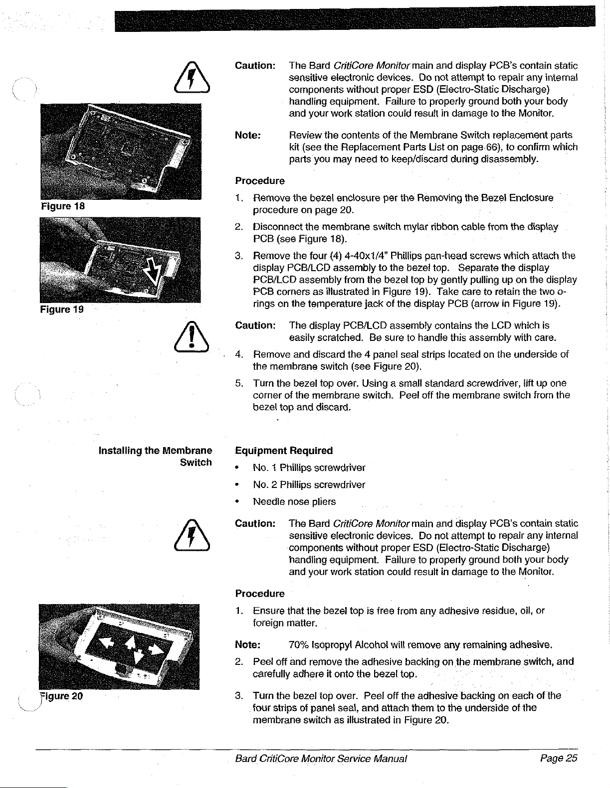
Caution:
个
a
The
Bard
CritiCore
sensitive
electronic
components
handling
and
equipment.
your
work
Monitor
devices.
without
station
proper
Failure
could
main
and
display
Do
not
attempt
ESD
(Electro-Static
to
properly
resuit
in
damage
PCB's
to
ground
to
contain
repair
any
Discharge)
both
your
the
Monitor.
static
internal
body
Figure
Figure
18
19
Note:
Procedure
1.
Remove
procedure
2.
Disconnect
PCB
3.
Remove
display
PCB/LCD
PCB
rings
Caution:
4.
Remove
the
5.
Turn
comer
bezel
Review
kit
parts
the
on
(see
Figure
the
PCB/LCD
assembly
corners
on
the
The
easily
and
membrane
the
bezel
of
the
top
and
the
contents
(see
the
Replacement
you
may
bezel
enclosure
page
20.
the
membrane
18).
four
(4)
assembly
as
ilustrated
temperature
display
scratched.
discard
switch
top
over.
membrane
discard,
of
need
to
per
switch
4-40x1/4”
to
from
the
bezel
in
Figure
jack
of
PCB/LCD
Be
sure
the 4 panel
(see
Figure
Using a small
switch.
the
Membrane
Parts
List
keep/discard
the
Removing
mylar
ribbon
Phillips
the
assembly
bezel
top
the
to
seal
20).
Peel
pan-head
top.
by
gently
19).
Take
dispiay
contains
handle
strips
standard
off
the
Switch
on
page
during
the
cable
screws
Separate
pulling
care
PCB
(arrow
the
this
assembly
located
screwdriver,
membrane
replacement
66),
to
confirm
disassembly.
Bezel
Enclosure
from
the
display
which
attach
the
display
up on
the
to
retain
the
in
Figure
LCD
which
with
care.
on
the
underside
lift
up
switch
from
parts
which
the
display
two
o-
19).
is
of
one
the
{
Na
Figure
20
Installing
the
Membrane
Switch
7
Equipment
*
No. 1 Phillips
*
No. 2 Phillips
*
Needle
Required
nose
Caution: . The
sensitive
components
handling
and
Procedure
1.
Ensure
foreign
Note:
2.
Peel
carefully
3.
Turn
four
that
matter.
70%
off
and
adhere
the
bezel
strips
of
membrane
screwdriver
screwdriver
pliers
Bard
CritiCore
electronic
equipment.
your
work
the
bezel
lsopropyl
remove
panel
switch
it
top
the
onto
over.
seal,
as
Monitor
devices.
without
proper
Failure
station
top
Alcohol
is
could
free
will
adhesive
the
bezel
Peel
off
and
attach
illustrated
in
main
Do
ESD
to
result
from
remove
backing
top.
the
adhesive
them
Figure
and
display
not
attempt
(Electro-Static
properly
any
ground
in
damage
adhesive
any
remaining
on
the.
membrane
backing
to
the
underside
20.
PCB's
to
repair
Discharge)
both
to
the
residue,
adhesive.
on
each
of
contain
any
your
static
internal
body
Monitor.
oil,
or
switch,
of
the
the
and
Bard
CritiCore
Monitor
Service
Manual
Page
25
Page 32

Caution:
Panel
seal
strips
overlapping.
should
meet
É
flush
in
the
corners
with no
г
№
Note:
4.
5.
6.
7.
Figure
Display
The
between
the
The
electrical
The
Ensure
the
Install
ihe
alignment
pan-head
Reconnect
(see
Figure
Install
the
procedure
Perform
ali
display
PCB
display
bezel
display
display
PCB
the
top,
PCB
and
PCB
that
membrane
display
of
temperature
screws.
the
membrane
21).
bezel
enclosure
on
page
the
Functional
and
general
(Printed
user
and
and
is
contains
mechanical
also
there
is
no
lint
or
switch
PCB/LCD
21.
Checkout
CritiCore
Circuit
the
main
connected
ihe
connections
contains a temperature
before
assembly
jack,
by
switch
per
the
Board)
PCB.
to
the
LCD
installing
mylar
Installing
procedure
Monitor
provides
The
main
driver
with
foreign
proceeding
display
electronics
matter
to
the
bezel
the
four
connector
the
Bezel
(see
functions:are
the
PCB
PCB
with
the
LCD.
jack
and a phototransistor:
on
the
with
the
top
ensuring
(4)
4-40x1/4”
to
the
Enclosure
page
7)
working
transfer:
is
directly
the
display
and
provides
LCD
or
on
installation.
Phillips
display
to
ensure
of
data
attached
cable.
PCB
that
property.
the
to
Testing
Figure
22
the
Display
Electronics
PCB
The
temperature
utilizing a mono
of a 400-Series
The
phototransistor
diode
and
detector
collection
Procedure
1.
container.
Perform
function
problem(s)
*
+
*
the
of
Testing
Testing
Testing
Temperature
The
temperature
the
procedures
connecior.
Note:
Before
LCD
indicators
jack
provides
phone
thermistor
the
to
the
the
the
plug.
contains
are
designed
Functional:
display
the
display
Phototransistor
Temperature
Liquid
Jack
jack
connector
below
to
test,
you
test
procedure
are
an
insertion
The
Monitor
into
the
appropriate
an
IR
emitting
to
detect
Checkout
PCB.
PCB.
Crystal
remove,
the
(on
functioning
procedure
Refer
(page
Jack
Display
is
available
temperature
page
30)
properly.
site
for a temperature
is
designed
relative
diode
the
cap
to
to
the
following
55)
(page
27)
(LCD)
as a replacement
and
install
jack,
to
verify
convert
temperature
and
IR
on
the
verify
tests
(page
30)
the
temperature
perform
that
all
probe
the
resistance
reading.
photodetector.
disposable
the
suspect
to
the
LCD
isolate
part.
Testing
status
the
Follow.
jack
the
The
了
~
ゝ
jj
:
Page
26
Bard
CritiCore
Monitor
Service
Manual
Page 33

Testing
the
Temperature
Jack
Connector
Equipment
*
Calibration
Procedure
1.
Turn
2.
Connect a calibration
jack
reading
will
on
3.
Verify
and
intermittent
must
Required
the
Monitor
on
the
in
the
vary
depending
the
Monitor).
that
there
pulling the
be
repiaced.
piug
display
Bladder
readings
or
temperature-sensing
on.
plug
or
temperature-sensing
assembly.
on
are
no
probe
Temperature
the
intermittent
out
are
Note
air
temperature
and
plugging
observed
Foley
that
there
window
readings
it
back
during
this
catheter
should
of
the
as
well
by
in
test,
Foley
catheter
be a temperature
display
as
gently
several
the
(The
the
F°
moving
times.
temperature
to:the
readings
or © setting
the
probe,
If
jack
Note:
Removing
the
Temperature
Jack
Connector
Equipment
e
‘No.1
+
No. 2 Phillips
*
Small
+
Needle
e
Desoldering
Caution:
Note:
Phillips
standard
nose
Figure
23
The
calibration
adjusting
your
and
information.
Required
The
static
internal
Discharge)
your
Monitor.
Review
kit
(see
which
any
Monitor
Calibrating
screwdriver
screwdriver
screwdriver
pliers
tools
Bard
CritiCore
sensitive
components
handling
body
and
the
contents
the
Replacement
parts
you
of
Bladder
components
is
out
of
temperature
the
Main
Monitor
electronic
without
equipment.
your
work
of
the
may
need
Temperature
on
the
display
calibration,
PCB
procedure
main
and
devices.
station
temperature
Parts
to
Do
proper
Failure
could
List
on
keep/discard
is
not
performed
PCB.
see
(on
page
:
display
ESD
PCB’s
not
attempt
(Electro-Static
to
properly
result
in
jack
replacement
page
64),
during
by
If
you
suspect
the
Installing
58)
for
contain
to
repair
ground
damage
to
to
confirm
disassembly.
any
both
the
parts
Procedure
1.
Remove
procedure
2..
Disconnect
PCB
3.
Remove
assembly
from
iltustrated
Bard
CritiCore
(see
the
the
bezel
on
page
the
Figure
the
four
to
the
bezel
in
Figure
Monitor
enclosure
20.
membrane
23).
assembly
bezel
top
by
gently
24.
Service
top.
per
the
switch
Manual
mylar
screws
Separate
pulling
Removing
ribbon:cable
which
attach.
the
display
up
on the
the
Bezel
Enclosure
from
the
the
display.
PCB/LCD-assembly.
display:
PCB
PCB/LCD.
comers
display
as.
Page
27
Page 34
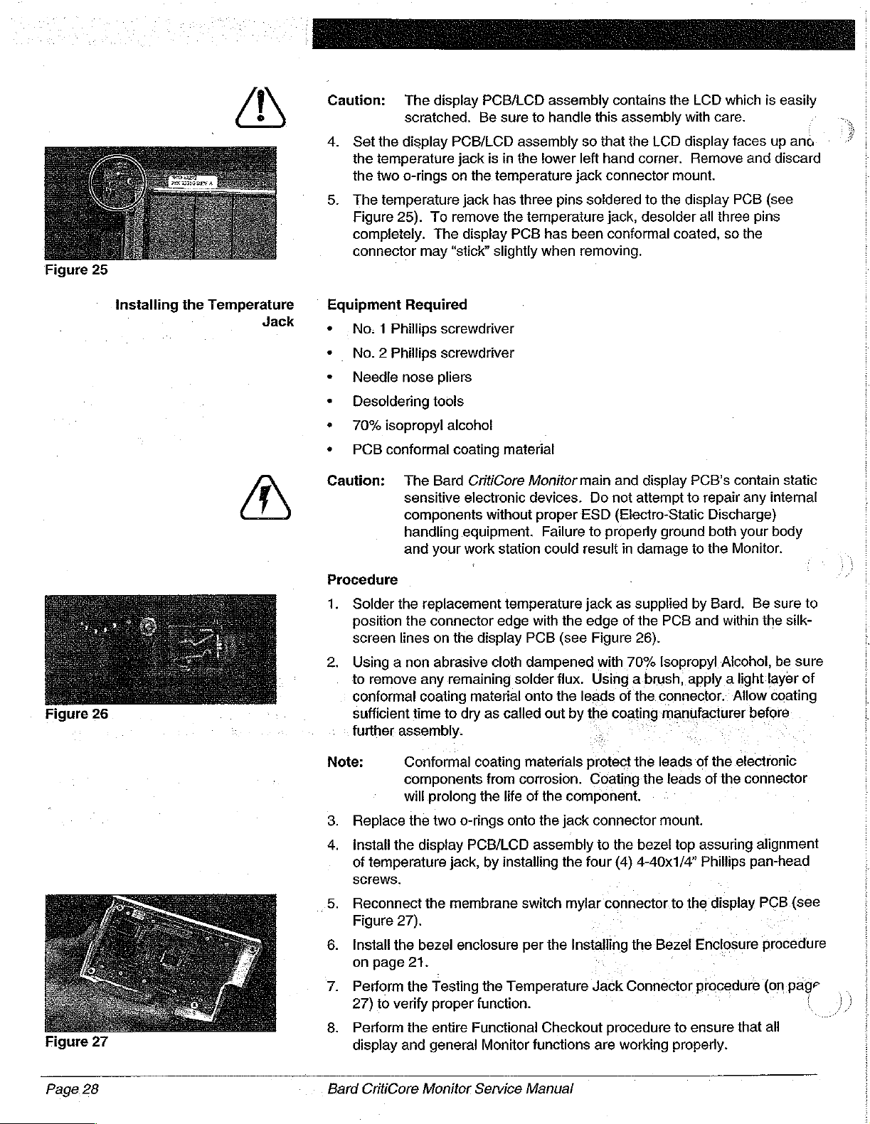
Figure
25
>
Caution:
4.
Set
the
the
temperature
the
two
5.
The
Figure
completely.
connector
The
display
scratched.
display
o-rings
temperature
25).
To
The
may
PCB/LCD
on
remove
“stick”
PCB/LCD
Be
jack
is
the
temperature
jack
has
display
slightly
sure
to
assembly
in
the
lower
three
the
temperature
PCB
has
when
assembly
handle
so
left
jack
pins
soldered
been
removing.
this
contains
assembly
that
the
LCD
hand
corner.
connector
to
jack,
desolder
conformal
the
with
display
Remove
mount.
the
display
coated,
LCD
all
which
care.
faces
PCB
three
so
the
and
pins
is
easily
up
ano
discard
(see
Figure
26
installing
the
Temperature
Jack
4
Equipment
+
.No. 1 Phillips
+
No. 2 Phillips
+
Needle
«
Desoldering
s
70%
isopropyl
+
PCB
conformal
Caution:
Procedure
1.
Solder
position
screen
2.
Using a non
to
remove
conformal
sufficient
further
Required
screwdriver
screwdriver
nose
pliers
tools
alcohol
coating
The
Bard
sensitive
components
handling
and
your
the
replacement
the
connector
lines
on
the
abrasive
any
remaining
coating
time
to
assembly.
material
CritiCore
electronic
without
equipment.
work
station
temperature
edge
display
cloth
solder
material
dry
as
called
Monitor
devices.
proper
Failure
could
with
the
PCB
(see
dampened
flux.
onto
the
out
by
main
and
display
Do
not
attempt
ESD
(Electro-Static
to
properly
result
in
damage
jack
as
supplied
edge
of
the
Figure
Using a brush,
leads
the
`
with
70%
of
coating
26).
the
PCB's
contain
to
repair
Discharge)
ground
PCB
Isopropyl
connector..
manufacturer
both
to
the
Monitor.
by
Bard.
and
within
Alcohol,
apply a light
Allow
any
your
Be
the
layer
before
static
internal
body
sure
to
silk-
be
sure
of
coating
Figure
Page.28
27
Note:
3.
Replace
install
of
screws.
5.
Reconnect
Figure
6.
Install
on
7.
Perform
27)
8.
Perform
display
Bard
Conformal
components
will
prolong
the
the
display
temperature
the
27).
the
bezel
page
21.
the
to
verify
the
and
general
CritiCore
Monitor
coating
two
o-rings
PCB/LCD
jack,
membrane
enclosure
Testing
proper
entire
Functional
Service
materials
from
corrosion.
the
life
of
onto
assembly
by
installing
switch
per
the
Temperature
function.
Monitor
functions
Manual
protect
the
component.
the
jack
the
four
mylar
the
Installing
Checkout
the
Coating
connector
to
Jack
are
the
the
bezel
(4)
4-40x1/4”
connector.to
the
Connector
procedure
working
leads
of
the
leads
of
mount.
top
assuring
Phillips
the
display
Bezel
Enclosure
、
procedure
to
ensure
properly.
electronic
the
connector
alignment
pan-head
PCB
procedure
(on
that
all
(see
page
|
Page 35

Liquid Crystal
The
LCD
is a custom
information
strips
which
pads.
zebra
to
and
“zebra”
provide
The
zebra
strips
between
the
electrical
Display
segmented
user.
The
retainers.
contact
retainer
the
provides
display
(LCD)
glass
LCD
is
Zebra
between
PCB
panel
attached
strips
are
the
that
mechanical
and
which
to
soft,
display
LCD.
provides
the
display
compressible
PCB
and
support
functional
PCB
via
“zebra”
foam
LCD
contact
to.
compress
strips
the
Testing
the
Liquid
Display
Crystal
(LCD)
Note:
Visuaily
broken,
If it
inspect
it
is
suspected
properly,
another
on
Procedure
page
component
13)
There
membrane
and
The
onto
use
area.
Gridlines
the
membrane
that
must
it
will
be
for
are
two
switch
were
used
current
the
viewing
with
an
provide
LCD.
If
switch,
gridlines
the
LCD
be
replaced.
that.a
segment
necessary
of
the
details.
versions
had
with
an
membrane
area.
LCD
which
distinct
you
need
you
are visible
for
damage.
or
to
determine
Monitor.
of
the
LCD.
gridlines
LCD
that
switch
This
has
to
will
status
does
membrane
gridlines
separation
replace
need
to
the
user.
If
the
indicator
if
See
the
Early
versions
screened
did
an
to
LCD
the
onto
not
have
not
have
switch
screened
between
early
version
replace
is
cracked
is
not
problem
the
gridlines.
gridlines
is
onto
the 6 sections
the
LCD
being
is
the
Troubleshooting
of
the
viewing
screened
designed
the
of
the
to
ensure
or
physically
displayed
LCD,
section
area,
for
viewing
of
or
(starting
—
Figure
Dauer
28
1.
Tum
the
SWITCH
Note:
For
purposes
categories:
Segment
Present
Prior
Output
Container
Status
Check
alarm
2.
Turn
the
complete a self
test
all
display
Bard
CritiCore
Monitor
to
H
you
TEST
the
have
SWITCH
off.
T,
position.
COMMUNICATIONS
of
this
Segment
groups
Interval
will
Output,
interval
Volume.
Indicators
Container,
bell
icon,
Monitor
will
Low
etc.
on
test
of
the
segment
should
resemble
Monitor
Service
Open
the
rear
control
Close
the
rear
installed a CritiCore
label
has
MODULE
test,
the
display
groups
refer
Ending
refer
while
cycle
and
to
the
Bladder
Time,
to
all
Battery,
observing
lasting
groups
and
Figure
seven
Temperature,
of
AM
approximately
28.
Communications
been
replaced
label...
will
status
groups
Prior
Output
the
remaining
and
PMindicators,
the
display:
status
Manual
panel
door
control
be
by
broken
panel
a
up
indicators:
of
numeric.
Time,
Volume
indicators;
“The
4-seconds.
indicators
will
:
and
set
door.
Module,
into
two
indicators
interval
and
MLU/HR
Monitor
During
be
lit,
the
TEST
your
main
:
for-
Lengih...
Flow.
Rate!
Set
Value,
indicator,
will
first
this
and
the
Page
29
Page 36

3.
Following
and
the
status
self
test,
indicators
in
the
display
the
following
will
begin
manner:
to
“cycle”
segment
groups
Figure
30
Note:
The
hexadecimal
displaying
step,
All
status
through
0,
2,
example.
All
status
through
1,
3,
for
an
4.
ff
the
main
section
Depending
with a different
will
repeat
position,
segment
remaining
4,
5, 7,
example.
Monitor
PCB.
groups
values,
the
same
indicators
the
following:
6, 8,
A,
indicators
the
following:
9,
does
You
on
page
at
b,
can
58),
on
the
value
itself until
or
until
the
will
begin
with
number
each
step
will
not
C,
E,
will
be
d,
F,
not
cycle
either
or
return
internal
than
the
TEST
Monitor
to
each
individual
or
letter.
for
approximately
turn
on
0,
2, 4,
turned
1,
3,
5, 7,
through
replace
the
state
of
that
which
SWITCH
is
turned
cycle
through
The
when
6,
8,
on
when
9,
as
described,
the
main
Monitor
the
CPU,
is
listed
off.
successive
segment
display
1.5
the
segment
“”,
L, E see
the
segment
H,
P,
PCB
to
Bard
the
betow.
is
moved
of
each
will
cycle
seconds.
values
(blank)
you
(refer
for
service.
“cycle”
Figure
values
may
to
may
This
off
of
decimal
segment
through
cycle
29
cycle
see
Figure
have a faulty
the
Main
cycle
the
for
start
T,
and
group
each
an
30
PCB
Removing
Crystal
Figure
Figure
31
32
the
Liquid
Display
°
(LCD)
4
Equipment
+
No. 2 Phillips
+.
No. 1 Phillips
*
Small
+
Needle
Caution:
Note:
Procedure
1.
Remove
procedure
2.
Disconnect
PCB
(see
3.
Remove
display
PCB/LCD
display
two
o-rings
32).
Required
standard
nose
pliers
The
Bard
sensitive
components
handling
and
your
Review
Replacement
may
need
the
bezel
on
the
Figure
the
four
PCB/LCD
assembly
PCB
corners
on
head
screwdriver
head
screwdriver
screwdriver
CritiCore
electronic
without
equipment.
work
the
contents
Parts
to
keep/discard
enclosure
page
20.
membrane
31).
(4)
4-40x1/4”
assembly
from
as
the
temperature
Monitor
devices.
proper
Failure
station
could
of
the
List
on
per
switch
Phillips.
to
the
the
bezel
illustrated
jack
main
ESD
to
result
LCD
page
during
the
Removing
mylar
bezel
top
in
Figure
of
and
display
Do
not
attempt
(Electro-Static
properly
replacement
64),
disassembly.
ribbon
pan-head
top.
by
the
ground
in
damage
to
confirm
the
cable
screws
Separate
gently
pulling
32:
Take
display
PCB’s
to
to
parts
Bezel
from
care
PCB
contain
repair
any
Discharge)
both
your
the
Monitor.
kit
(see
which
paris
Enciosure
the
display
which
attach
the
display
up
on
the
to
retain
(arrow
in
Figure
:
static
internal
body
the
you
:
the
DA
the“
1%
i
,
Page
30
Bard
CritiCore
Monitor
Service
Manual
Page 37

Caution:
4,
Place
Ensure
display
The
easily
the
display
that
PCB
display
scratched.
PCB/LCD
the
two
are
positioned
PCB/LCD
Be
solder
connections
assembly
sure
to
assembly
to
your
lower
contains
handle
so
that
“ELP1”
ieft
this
the
and
(see
the
LCD
assembly
LCD
is
facing
“ELP2”
Figure
33).
which
with
care.
upwards.
on
the
is
Note:
Figure
Figure
33
34
Installing
the
Liquid
Display
Crystal
(LCD)
5.
Using a No. 1 Phillips
2-56x5/16”
washers
6.
Gently
34.
the
panel
strips
Equipment
s
No. 2 Phillips
*
No. 1 Phillips
‧
Needle
Caution:
Before
“sandwiched”
that
bordered
ELP2.
pull
The zebra
retainers
is still
from
Required
nose
The
sensitive
components
handling
and
further
the
backlight
Phillips
securing
the
zebra
strips
with
soldered
the
zebra
head
head
pliers
Bard
your
disassembly,
between
(the
by
the
zebra
head
pan-head
the
zebra
retainers
may
“stick”
increasing
to
ELP1
retainer.
screwdriver
screwdriver
CritiCore
electronic
without
equipment.
work
station
note
the
LCD
light
green
retainers
screwdriver,
screws,
retainer
away
force.
and
Monitor
devices.
proper
Failure
could
to
to
the
Be
ELP2.
main-and
ESD.
result.
2-56
the
from
LCD,
careful
Do
to
properly
that
the
pink
zebra
and
the
display
panel)
and
remove
not-attempt
(Electro-Static
is
lying
soldered
hex
nuts,
display
the
LCD
so
you
to
Remove
display
in.damage.to
into
the
nine
and
PCB.
as
illustrated
may
note
that
the
PCB’s
to
ground
LCD,
repair
strips
PCB.
Also
below
the
LCD,
ELP1
and
(9)
#2
nylon
in
have
to
pull
the
backlight
and
zebra
contain
any
internal
Discharge)
both
your
body
the
Monitor.
are
note
Figure
at
static
Procedure
Note:
1.
Figure
Figure
35
36
2.
3.
4.
Bard
This
procedure
converse
handed
Inspect
of
rubbing
alcohol.
assembly.
Inspect
contamination
rubbing
70%
Place
soft,
Position
connection
the
conductor
any
contamination
the
pads
Ensure
the
LCD
the
pads
isopropyl
the
Display
surface),
the
edges,
LCD
36).
CritiCore
Monitor
was
written
of
all
highlighted
individuals.
pads
of
the
(oil,
dirt,
etc.)
with a non-abrasive
that
your
hands
pads
and
zebra
(oil,
dirt,
etc.).
You
and
retainers
with a non-abrasive-cloth
alcohol.
PCB
with
the
so
that
the
display
in
your
left
hand
with
the
back
Service
Manual
for
right-handed
position
display
You
can
cloth
are
free
strips.
conductor
(papered
Ensure
can clean
cable
is
so
you
identifiers
PCB.
Ensure
clean
the
dampened
of
oil
and
that
these
components
E
pads
face
facing
hold
side)
you.
the
LCD
facing
individuals.
will
work
for
that
they
pads
by
with
70%
dirt
before
they
down
(see
up
further
are
free
dampened
(on a clean
Figure
along
it’s
(see
Figure
The
left-
are
free
gently
isopropyl
:
of
any
by
gently
with
35).
pad
Page
31
Page 38

Figure
Figure
37
38
Figure
39
Figure
40
5.
On
“bump”
6.
Insert
that
‘
fall
Note:
7.
Carefully
{see
8.
Pick
backlight
9.
Once
assembly
10.
Genily
the
40).
11.
Carefully
holes
nine
corner
directly
12.
Place
tighten.
13.
Replace
14.
Instail
alignment
pan-head
15.
Reconnect
16.
Install
procedure
17.
Perform
of
18.
Perform
all
one
of
is
the
the
retainer’s
slightly
For
to
Figure
Figure
up
the
the
turn
zebra
match
(9)
2-56x5/16”
holes,
under
the
-Tighten
the
the
the
the
the
LCD
the
display
the
edges
towards
long
edges
flanges
inwards
next
few
ensure
insert
over
backlight
in
retainers
position
#2
display
of
screws.
the
bezel
on
segments
and
that
37).
the
38).
display
the
LCD
your
left
the
entire
the
the
display
and
then
the
display
nylon
to
two
o-rings
PCB/LCD
temperature
membrane
enclosure
page
Testing
Functional
general
of
the
LCD
your
left
(see
of
the
LCD
are
facing
as
you
hold
steps,
zebra
PCB
is
against
Phillips
washer
approximately
21.
the
it
is
the
LCD
strips
with
your
and
between
slid
into
place,
hand.
assembly
the
LCD
assembly
PCB
holes.
pan-head
the
remaining
cable).
and
onto
the
assembly
jack,
switch
per
the
LCD
procedure
and’status
Checkout
Monitor
there
is a small
arrow
in
into
the
upwards.
the
assembly
important
is
seated
into
their
right
hand
the
lay
the
over
into
LCD
and
the
so
that
When
screws
five
2-56
hex
2.5
in/lbs.
temperature
to
by
installing
mylar
connector
installing
(on
indicators
procedure
functions
“bump”.
Figure
zebra
into
appropriate
zebra
your
(5)
nut
the
are
36).
retainers,
The
in
your
to
keep
the
and
retainers
display
right
display
the
zebra
the
holes
beginning
holes
onto
of
torque.
jack.
bezel
the
four
-
the
Bezel
page
are
functioning
(on
page
working
just
zebra
each
to
29)
Ensure
making
retainers
hand.
enough
retainers
slots
in
carefully
PCB
hand,
PCB
(excluding
top,
(4)
the
guide
(see
onto
while
(see
retainer
are
lined
with
screw
assuring
4-40x1/4”
display
Enclosure
to
confirm
properly.
7)
to
ensure
properly.
that
sure
may
want
pressure
(see
the
retainer.
the
Figure
the
LCD
keeping
Figure
mounting
up,
insert
the
four
the
hole
and
Phillips
PCB.
that
the
39).
all
that
©
to
?
Figure
Page
41
32
Testing
the
Arms
Arms
The
Bard
CritiCore
such
as a hospital
enclosure
Monitor
to
The
bearing
Procedure
1.
Bard
to
the front
arm
is
that
Visually
armís)
CritiCore
Monitor
bed
and
must
hang
on a level
enclosure.
secured
is
inspect
must
to
press-fit
be
replaced.
Monitor
rail.
move
the
into
each
Service
arm,
arms
allow
The arms
unhindered.
plane.
enclosure
the
The
by a shoulder
arm.
if
either
Manual
the
are
directly
The
arms
arm
Monitor
attached
movement
also
indirectly
、
is
bent,
to
be
hung.on
of
the
attach
screw,
which
cracked,
to
or
the
arms
an
object
front
allow
the
handle
rides
ona
broken,
the
ZÁ
the
Page 39

2.
3.
4,
Turn
the
movement
Figure
Monitor
to
Each
similar
raise
Repeat
raises
the
42
see
if
arm
molded
as
the
handie
in
step 2 and
Monitor
indicates,
itis
contains a molded,
the
handle.
so
that
for
each
arm.
and
Figure
42
If
contaminated.
arm
or
the
plastic
step
is
raised.
raise
if
the
arm
has a broken
you
move
the
each
handle
are
The
arm
on
facing
arm
should
freely
to
does
not
internal
the
arm.
handle.
Verify
does
plastic
plastic
not
the
front.
rest
the
position
move
This
that
raise
step.
Note
as
the
freely,
step
which
causes
each
with
the
left
Monitor
shown
inspect
catches
the
arm
catches
each
range
of
in
in
the
right
the
bearing
ona
handle
and
arm, then
to
either
Equipment
+
Small
+
Standard
+
9/6”
socket
Note:
Procedure
1. . Remove
between
2.
Remove
Figure
Note:
3.
Visually
would cause
bearing
with
70%
silicone-based
Required
jeweler’s
screwdriver
and
Review
Replacement
may
need
the
arm
the
arm
the
shoulder screw
44.
There
are
and a hex
a
smail
screw
is
screwdriver
driver
to
inspect
it
to
with
either
Isopropyl
lubricant
screwdriver
driver
the
contents
Parts
to
keep/discard
cap
by
inserting a small
cap
and
the
two
shoulder
head
screw.
washer.
not
remove:the
the
bind
Keep
available
for
the
slotted
bearing
up.
If
compressed
Alcohol.
to
the
of
the
Arm
replacement
List
on
page
64),
during
arm
as
to
separate
screw
The
this
as a replacement.
head
hex
head
to
verify
the
bearing
air
If
available,
bearing:
disassembly.
flat
illustrated
the
configurations;
slotted
washer
or
only
screw
screw.
that
there
is
contaminated,
anon
apply
parts
to
confirm
head
in
arm
from
shoulder
if a hex
and a 3/8”
is.
abrasive
two
which
jeweler’s
Figure
the
slotted
screw
head
Use a large
ne.contamination
cloth
drops.
kit
(see
parts
screwdriver
43.
enclosure
head
is
used
shoulder
flat
head
hex
head
clean
out the
dampened
of a non-
the
you
as
in
screw
with
nut
which
Note:
Figure
45
4.
Bard
Visually
on
If
Some
plastic
material
inspect
the
inside
either
step
CritiCore
Monitor
oils
have
enclosure.
of
the
the
molded
of
the
arm. Item B is
is
cracked
Service
chemical
Use
arms.
plastic
or
broken,
Manual
compounds
only
oil/grease
steps.
the
the
which
which
Item A in
step
on
the
respective
may
will
Figure
outside
part
must
attack
not
attack
45
of
the
be
the
the
is
the
step
handle.
replaced.
Page
33
Page 40

Figure
46
Figure
47
5.
If
the
the
hook
between
6.
Using a small
arm
insert
arm
must
caps
each
and
be
replaced,
by
inserting a small
hook
cap
and
jeweler’s
remove
screwdriver
the
the
the
hook
hooks
need
flat
head
arm
as
illustrated
or
wire,
as
illustrated
to
be
removed.
jewelers
in
push
the
in
Figure
Separate
screwdriver
Figure
dowel
47.
46.
pin
out
of
the
Installing
the
Arms
Equipment
・
Standard
*
3/8"
Note:
Procedure
1.
If
the
handle
installing
2.
Replace
Replace
Note:
3.
Reattach
and
the
4.
Perform
move
Required
socket
Do
from
handle
has
the
the
Ensure
With
hook(s)-
{see
arm
insert.
arm.
the
freely.
the
screwdriver
and
driver
not
pre-lubricate
Bard.
was
removed
been
attached
Handle
shoulder
arm
cap.
that
the
the
Monitor
openings
left
Monitor
the
hook
to
Secure
Testing
the
the
prior
in
the
procedure
screw,
the
tightening
hook
facing
should
in
Figure
arm
the
dowel
Arms
fs
by
procedure
bearing
to
proper
on
installed
you
in a replacement
arm
installation,
orientation
page
35).
the
with
and.the
face
towards
42).
inserting
pin
by
screw
to
the
proper
arms
hanging
the
the
dowel
replacing
(page
32)
arm
ensure
(see
the
15in/Ibs.
orientation.
down,
front
of
pin
through
the
hook
to
verify
received
that
the,
note
of
the
Monitor
caps
that
in
the
torque.
the
É
the
hook
onto
the
arms
-
Figure
Page
48
34
Testing
the
Handle
Handle
The
Bard
CritiCore
transported.
when
the
Monitor
away
from
any
plane.
attached
Procedure
1.
2.
Bard
The
to
the
Visually
handle
Each
plastic
raised.
must
handle
step
CritiCore
handlé
Inspect
Monitor
The
handle
is
objects
arm,
be
contains a molded,
on
Monitor
also
hung
by
so as
raises
when
which
is
the
handle,
replaced.
the
arm. This
Service
handle
keeps
the
hooks.
to
allow
the
attached
if
causes
Manual
allows.the
the
Monitor
It
is
the
Monitor
arm(s)
the
are
to
the
handle
plastic
the
Monitor
pushed
necessary
to
hang
raised.
front
enclosure.
is
cracked
step
which
handle
to
be
away
to
The
or
catches
to
raise
easily
from
keep
freely
on a level
handle
broken,
as
an.object
the
Monitor
is
the
on a molded
the
arm
is
n
Page 41

3.
Raise
the
handle.
handie
each
or
the
arm
If
the
arm
of
the
Monitor.
handle
has a broken
does
Verify
that
not raise
plastic
step.
each
with
arm
each
catches
arm,
then
and
raises
either
the
Removing
Figure
49
Installing
the
the
Handle
Handle
Equipment
*
Small
+
Standard
+
3/8"
Procedure
Note:
1.
Remove
procedure
2.
Visually
item B in
replaced.
3.
Pull
Equipment
*
Standard
*
3/8”
Required
jewelers
socket
Review
Replacement
may
inspect
outwards
Required
socket
screwdriver
screwdriver
and
driver
the
contents
need
to
both
arms
from
on
page
33.
the
Figure
49),
on
the
screwdriver
and
driver
of
the
Parts
List
keep/discard
the
Monitor
molded,
if
handle
the
plastic
step
ends
is
Handie
on
page
during
per
step
cracked
to
release
replacement
64),
to
confirm
disassembly.
the
Removing
on
the
ends
or
broken,
it
from
the
the
of
the
front
parts
which
Arms
the
handle
handle
kit
(see
parts
you
(see
must
enclosure.
the
be
Figure
50
Testing
the
Hooks
Procedure
Note:
1.
Pull
enclosure.
Install
3.
Perform
operation.
Hooks
Each
Bard
allow
the
hooks
are
Visually
replaced.
Before
are
oriented
over
and
outwards
each
arm
the
CritiCore
Monitor
hinged
inspect
the
installing
the
Monitor,
slightly
on
the
per
Testing
Monitor
to
hang
to
the
hook.
the
the
proper
the
towards
handle
the
Installing
the
Handle
Hook
from
arm
by a dowel
If
the
handle,
way.
outer
the front
ends
procedure
is
attached
an
object
hook
ensure
With
step
of
to
install:
the
Arms
such
pin
is
bent,
that
the
the
handle
of:the
handle should
the
Monitor.
the
handie
procedure
on
page
to
the
arms
as a hospital
(see
Figure
stretched
molded
held
onto
on
34
to
and
bed
50).
or
broken
plastic
straight
be
the
front
page
34.
verify
proper
together
rail.
it
must
steps
up
down
:
they
The
be
Bard
CritiCore
Monitor
Service
Manual
Page
35
Page 42

Removing
the
Hooks
Equipment
*
Smali
Procedure
Required
standard screwdriver
Figure
51
Figure
Installing
52
the
Hooks
Note:
1.
Separate
between
2.
Using a small
insert
and
Procedure
1.
Replace
hook
and arm
orientation:
hook(s)
2.
Secure-the
3.
Visually
that
the
Front
The
and
and
front
remain
are
magnets
of
container.
seated’
signal
Enclosure
front
enclosure
select
attraction
of
the
seated
adhered
on
attraction
on
loss
Review
Replacement
may
need
the
hook caps
each
hook
jeweler’s
remove
the
hook
insert.
With
opening
dowel
inspect
hook
hardware.
Monitor.
to
the
is
The
the
when
the
moves
assembly
plates.
in
the
the
upper
bezel
necessary
force
transducer
the
the
contents
Parts
to
keep/discard
by
cap
and
screwdriver,
the
hook
onto
the
Ensure
the
Monitor
should
pin
hook
freely.
face
by
replacing
Assembly
Attached
The
plastic
These
container
retainers
Monitor,
portion
enclosure
to
apply
on
the
container
cap.
of
the
Hook
List
on
page
during
inserting a small
the
arm
as
push
as
illustrated
arm
by
inserting
that
the
hook
facing
you
towards
to
ensure
contains
to
the
retainers
and
atop
of
are
pressure
This
has
the
that
the
front
allow
the
the
Monitor
drawn
cap
in
turn
little
or
the
hook caps
ensures
no
replacement
64),
to
confirm
disassembly.
jeweler’s
illustrated
the
dowel
in
Figure
the
dowel
is
installed
and
the
front
of
the
hook
front
enclosure,
enclosure
are
located
for
the
disposable
transducer.
next
to
to
the
attraction
to
the
top
that
allows
fluid
inside.
for
parts
kit
which
screwdriver
in
Figure
pin
52.
arms hanging
the
Monitor.
onto
caps
are
the
on
The
the
of
the
the
minimal
51.
out
of
pin
through
with
the
the
arm.
are
secure
handle,
plastic
the
inside
container
attraction
arms.
The
plates.
disposable
container
ultrasound
(see
the
parts
you
the
arm
the
proper
down,
and
arms,
retainers
of
the
to
plates
The
force
is
firmly
the
Figure
Page
53
Testing
36
-
the
Front
Enclosure
Assembly
Directly
transducer/transducer
Note:
—_Vsuaily
broken
Bard
mounied
Figure
arms.
inspect
it
must
CritiCore
to
the
be
replaced.
Monitor
the
front
cap
and
53
illustrates
front
enclosure,
Service
enclosure
rear
enclosure.
the
front
if
the
Manual
are the
enclosure
front
display
enclosure
assembly,
without
is
the
cracked
main
handle
or
PCB,
and
Page 43

Removing
Enclosure
the
Front
Assembly
Equipment
e
Small
«
No. 2 Phillips
*
Needle
Required
standard
nose
pliers
screwdriver
screwdriver
AN
Caution:
Procedure
Note:
Remove
2.
Remove
procedure
3.
Remove
transducer,
enclosure.as
4.
Remove
the
the
The
static
internal
Discharge)
your
Monitor.
Review
(see
parts
main
main
Bard
sensitive
body
the
the
you
the
hooks
the
rear
on
page
the
two
and
illustrated
the
four
PCB
to
PCB.
CritiCore
electronic
componenis
handling
and
your
contents
Replacement
may
need
per the
enclosure
39.
(2)
6-32x3/8”
pull
(4)
the
Removing
out
the
in
Figure
6-32x3/16"
front
enclosure
Monitor
without
equipment.
work
of
to
per
transducer
main
devices.
station
the
front
Parts
keep/discard
the
Removing
Phillips
54.
Phillips
(see
and
Do
proper
Failure
could
enclosure
List
on
the
Hooks
pan-head
and
pan-head
Figure
display
ESD
page
during
the
transducer
PCB’s
not
attempt
(Electro-Static
to
properly
result
in
replacement
64},
disassembly.
procedure
Rear
screws
screws
55).
Lift
contain
to
repair
ground
damage
to
confirm
on
Enclosure
that
secure
cap from
which
up
and
to
the
parts
which
page
the
secure
remove
any
both
kit
36.
the
front
Installing
Enclosure
;
Figure
55
the
Front
Assembly
Equipment
e
Small
e
No. 2 Phillips
e
Needie
Caution:
Procedure
1.
Install
main
Note:
2.
Place
32x3/8"
front
cable
Required
standard
screwdriver
позе
pliers
The
Bard
static
sensitive
internal
Discharge)
your
body
Monitor.
the
four
PCB
to
the
Ensure
transducer
the
transducer
Phillips
enctosure
will
not
be
screwdriver
CritiCore
electronic
components
handling
and your
(4)
6-32x3/16”
front
enclosure
that
there
cap
or
cap
onto
pan-head
as
iftustrated
pinched
when
Monitor
devices.
without
equipment.
work
station
Phillips
(see
is
no
dirt,
transducer.
the
screws
in
Figure
the
and
main
and
display
Do
proper
pan-head
oil
transducer.
rear
ESD
Failure
could
Figure
55).
or
contamination
attach
the
54.
Ensure
enclosure
PCB’s
not
attempt
(Electro-Static
to
properly
result
in
screws
Install
transducer/cap
that
is
attached.
to
damage
and
on
the
two
the
transducer
contain
ground
attach
the
repair
to
the
the
(2) 6-
to
the
any
both
Bard
CritiCore
Monitor
Service
Manual
Page
37
Page 44

3.
Install
the
on
page
install
the
Perform
that
all
rear
40.
hooks
the
entire
display
enclosure
per
the
Functional
and
general
per
the
Installing
Installing
the
Checkout
Monitor
the
Hooks
procedure
functions
Rear
Enclosure
procedure
(on
are
working
on
page
page
properly.
procedure
36.
7)
to
ensure
Replacing
an
Attraction
Plate
个
Attraction
If
an
attraction
damaged,
and
the
Equipment
ον
small
* . Loctite
Procedure
1.
Remove
the
Try a dry
sits
2.
Place a small
Immediately
either
may
Caution:
Plates
the
bezel
enclosure
Required
chisel
454
any
front
enclosure.
fit
flush
in
side
have
squeezed
Loctite
precautions
handling
Allow
the
bond
Without a container
the
magnets
display
to
verify
enclosure.
plate
becomes
plate
may
or
hobby
Adhesive
remaining
with
the
the
recess.
amount
place
of
the
454
of
to
make
that
and
Magnets
be
replaced.
is
not
knite
(or
equivalent)
adhesive
This
can
replacement
of
Loctite
the
replacement
plate).
dry
Be
onto
contains
as
specified
this
adhesive.
as
specified
in
the
contact
the
attraction
the top
detached,
and
If a magnet
damaged,
residue
be
done
attraction
454
into
attraction
sure
to
wipe
side
cyanoacrylate.
by
the
by
Monitor,
with
completely
the
attraction
plate
the
front
has
the
magnet
in
the
with a small
plate
the
attraction
plate
away
of
the
plate.
Observe
manufacturer
the
manufacturer.
close
plates.
is
still.
bonded
OP
BEE
enclosure
become
may
be
attraction
chisel
to
ensure
plate
into
place
excess
AS
ES
adhesive
all
necessary
for
the
the
display
Lift
to
ihe.front
is
not
dislodged,
replaced.
plate
recess
or
hobby
that
the
recess.
(adhere
which
safe
so
up on
the
on
knife.
plate
to
that
Page
38
Replacing a Magnet
Equipment
+
Small
*
Loctite
Procedure
1.
Remove
bezel
Try a dry
flush
Bard
CritiCore
Required
chisel
or
hobby
454
Adhesive
any
remaining
enclosure.
fit
with
in
the
recess.
Monitor
knife
(or
adhesive
This
can
the
replacement
Service
equivalent)
residue
be
done
magnet
Manual
in
the
with a small
to
ensure
:
magnet
chisel
that
recess:on
or
hobby
the.
magnet
the
knife:
sits
 Loading...