

Bard CompleteStat CS9B-THOA, CompleteStat CS9B-THOCA, CompleteStat CS9BE-THOA, CompleteStat CS9BE-THOCA, CS9B-THOA Installation And Operation Manual
...Page 1
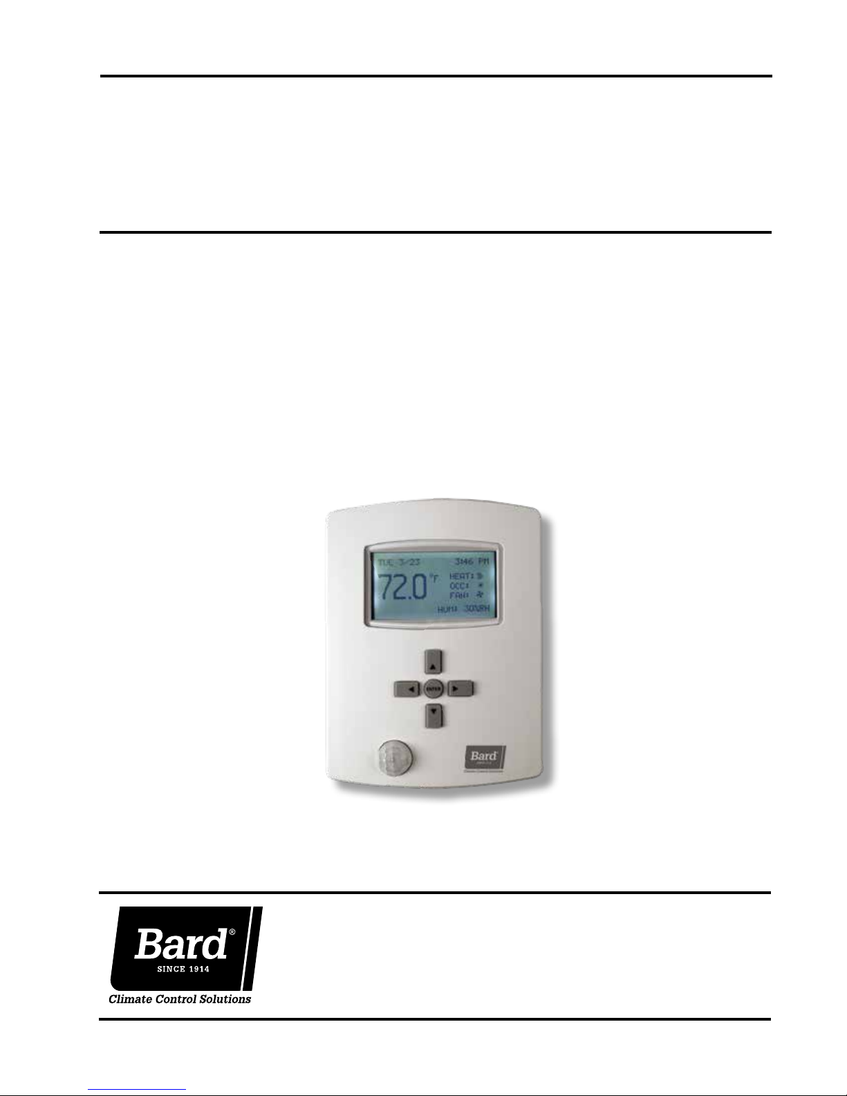
INSTALLATION, OPERATION &
QUICK START GUIDE
CompleteStat
Models:
CS9B-THOA
CS9B-THOCA
TM
Controller
CS9BE-THOA
CS9BE-THOCA
Bard Manufacturing Company, Inc.
Bryan, Ohio 43506
www.bardhvac.com
Manual: 2100-684
Supersedes: NEW
Date: 3-20-18
Page 1 of 25
Page 2

TABLE OF CONTENTS
INSTALLATION ........................................................3
Mounting Controller ............................................ 3
CompleteStat Setup Information .......................... 4
BASIC OPERATION .................................................5
Basic Setup ....................................................... 5
Quick Start Programming .................................... 5
System Selection ............................................. 5
Air Conditioner Applications ............................. 6
Heat Pump Applications................................... 7
System Enable ................................................ 9
Setpoints ........................................................ 9
Sequence of Operation ...................................... 10
WIRING DIAGRAMS .............................................15
FIGURES
Figure 1 CompleteStat Dimensions .................... 3
Figure 2 CompleteStat Buttons and Screens ....... 5
Figure 3 Application Menu ................................ 5
Figure 4 Additional Setup (Air Conditioner) ........ 6
Figure 5 Fan Setup (Air Conditioner) .................. 6
Figure 6 Dehumidification (Air Conditioner) ........ 7
Figure 7 Additional Setup (Heat Pump) .............. 7
Figure 8 Aux Heat Setup ................................. 7
Figure 9 Fan Setup (Heat Pump) ....................... 8
Figure 10 Dehumidification (Heat Pump) ............. 9
Figure 11 Additional Setup (Heat Pump) .............. 9
Figure 12 System Enable .................................... 9
Figure 13 Setpoints ........................................... 9
Figure 14 CompleteStat Terminal Descriptors
and Optional Inputs .......................... 11
TABLES
Table 1 Controller Connections ....................... 11
Table 2 Conventional 1H/1C, 2H/1C, 1H/2C
or 2H/2C without Econ ...................... 12
Table 3 Conventional 1H/1C, 2H/1C, 1H/2C
or 2H/2C with Econ ........................... 12
Table 4
Single Stage Heat Pump without Econ
Table 5 Two Stage Heat Pump without Econ .... 13
Table 6 Single Stage Heat Pump with Econ ..... 14
Table 7 Two Stage Heat Pump with Econ ........ 14
Table 8 Wiring Diagram Index ...................... 115
WIRING DIAGRAMS
WD 1 Conventional 1H/1C, 1H/2C, 2H/1C
or 2H/2C, with or without
Dehumidification and Ventilation,
No Economizer ................................. 16
WD 2 Conventional 1H/1C or 2H/1C with
TM
Honeywell W7220 JADE
Control
Economizer, with or without
Dehumidification .............................. 17
WD 3 Conventional 1H/2C or 2H/2C with
Honeywell W7220 JADE
TM
Control
Economizer, No Dehumidification,
2 Stage Compressor Only ................... 18
... 13
NOTE
Screenshots shown in this manual reflect
default settings (when applicable).
WD 4 Heat Pump 2H/1C or 3H/1C, with or
without Dehumidification and
Ventilation, No Economizer ................ 18
WD 5 Heat Pump 2 Stage, with or without
Dehumidification and Ventilation ........ 19
WD 6 Heat Pump 1 Stage with Honeywell
W7220 JADE
with or without Dehumidification ........ 19
WD 7 Heat Pump 2 Stage with W7220
JADE
TM
without Dehumidification ................... 20
WD 8 Gas/Electric 1H/1C, with or without
Dehumidification and Ventilation,
No Economizer ................................. 20
WD 9 Gas/Electric 1H/2C, with or without
Dehumidification and Ventilation,
No Economizer ................................. 21
WD 10 I-TEC
®
with No Ventilation ............................ 21
WD 11 I-TEC
®
with CRV Ventilation Package ............. 22
WD 12 I-TEC
®
with ERV Ventilation Package and
8403-067 CO
(Fully Modulating) ............................. 23
WD 13 Q-TEC
1 Stage Air Conditioner, with or
without Dehumidification and
Ventilation, No Economizer ............... 24
WD 14 Q-TEC
1 Stage Heat Pump, with or without
Dehumidification and Ventilation ........ 24
WD 15 QW*S Series 2 Stage Heat Pump,
with or without Dehumidification and
Ventilation ....................................... 25
WD 16 C**H Heat Pump 2 Stage with
W7220 JADE
with or without Dehumidification ........ 25
TM
Control Economizer,
Control Economizer, with or
2 Stage Heat Pump Series
2 Stage Heat Pump Series
2 Stage Heat Pump Series
Detector
2
TM
QA**/Q**A Series
TM
QH**/Q**H Series
TM
Control Economizer,
Manual 2100-684
Page 2 of 25
Page 3
INSTALLATION
IMPORTANT: For optimum temperature sensor
performance, the Bard CompleteStat must be mounted
on an interior wall and away from any heat sources,
sunlight, windows, air vents, air circulation obstructions
and/or any other cause of erratic or false temperature
sensing. Thermostat covers are not recommended as
they interfere with motion and temperature sensing.
Mounting Controller
1. It is recommended that18 AWG solid-conductor
control wire is used for installation. See the low
voltage wiring diagrams beginning on page 15 for
exact number of conductors.
NOTE: Shielded wire must be used in applications
where transient signals may accumulate and
affect digital signal from control to unit.
2. Turn the hex screws in the bottom and top of the
controller clockwise (inward) until they clear the
cover. Remove base plate from controller.
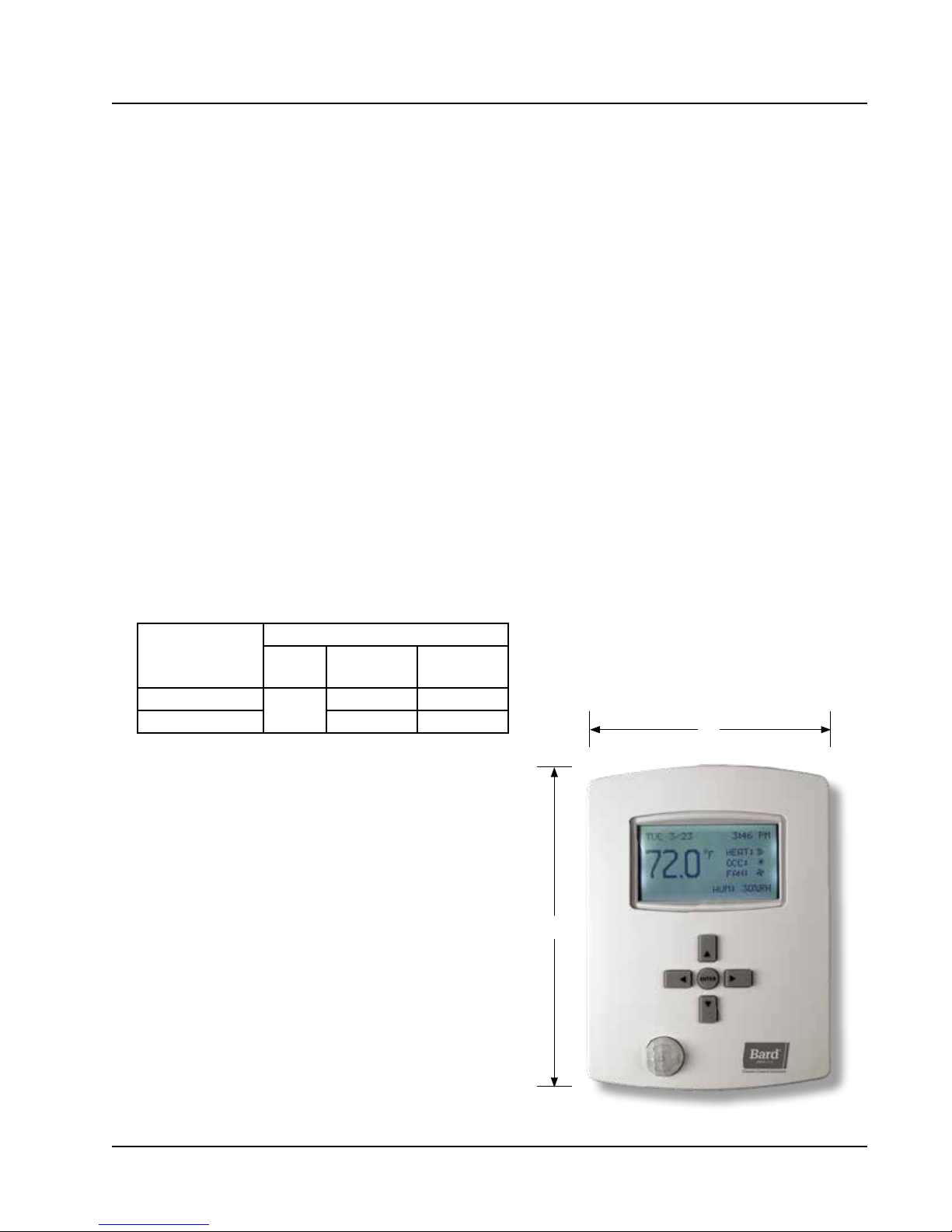
FIGURE 1
CompleteStat Dimensions
3. Route control wiring through base plate.
4. With the embossed “UP” arrows of the base plate
pointing in the appropriate direction, fasten the
base plate to the desired wall location. A vertical/
horizontal 2x4 wall handybox can be used for the
CO
-sensing CompleteStat and a vertical-only 2x4
2
wall handybox can be used for non-CO
-sensing
2
CompleteStat.
5. Make appropriate control wire connections to
terminal blocks. See low voltage wiring diagrams
beginning on page 15.
6. Replace controller over base plate, being careful
not to pinch/dislodge connections.
7. Turn hex screws in bottom/top of controller counterclockwise (outward) to secure cover.
Dimensions in Inches (mm)
Models
CS9B(E)-THOA
CS9B(E)-THOCA 5.192 (132) 1.437 (36.5)
Height
(A)
5.551
(141)
Width
(B)
4.192 (106) 1.125 (29)
Depth
B
A
Manual 2100-684
Page 3 of 25
Page 4

CompleteStat Setup at Time of Installation
Determine the following information prior to installation.
1. Degrees Scale: °F °C
2. Unit Type: A/C HP
3. Options: A/C – 1H/1C 2H/2C 1H/2C 2H/1C
HP – 1 Stage 2 Stage
4. Economizer: Yes No
5. Fan: Off Delay (seconds) Unoccupied: Auto On Occupied: Auto On
6. Humidity: Dehumidification Yes No
7. Humidity Setpoint:
8. Dehum Span:
9. Electric Strip Heat: Yes No
10. Reversing Valve: Active Htg Active Clg
11. System: Off Cool Heat Auto
12. Cool Setpoint:
13. Heat Setpoint:
14. Cool Setback:
15. Heat Setback:
16. Standby Time: Minutes
17. Motion Sensing: Daily Schedule
18. Date:
19. Time:
20. Occupied Minimum Cooling:
21. Occupied Maximum Cooling:
22. Unoccupied Minimum Cooling:
23. Unoccupied Maximum Cooling:
24. CO
25. CO
Setpoint:
2
Span :
2
NOTES _______________________________________________________________________________________
______________________________________________________________________________________________
______________________________________________________________________________________________
______________________________________________________________________________________________
______________________________________________________________________________________________
Manual 2100-684
Page 4 of 25
Page 5
BASIC OPERATION
BASIC SETUP
These instructions are intended to provide the basic settings to get the equipment started.
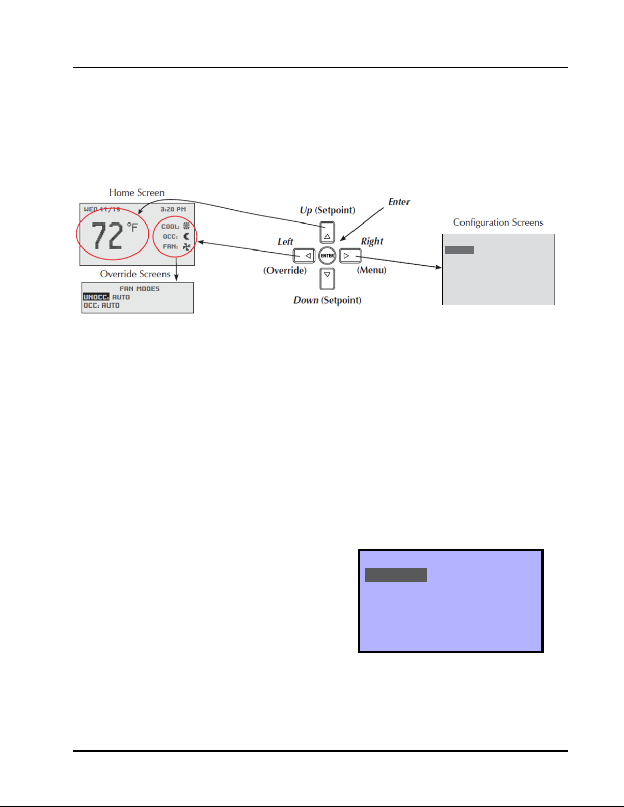
FIGURE 2
CompleteStat Buttons and Home, Overide and Configuration Screens
Navigate the menus and change settings by pressing a
combination of the four arrow buttons and the ENTER
button.
• ENTER button to select and/or exit value editing
• UP or DOWN button to move among entries
• RIGHT or LEFT button to move among value fields
• LEFT button to return to the home screen
NOTE: Although cooling/heating setpoints can be
accessed by simply pressing the UP or DOWN
buttons during normal operation, any changes
made in this fashion will not be permanent
but last only for a specific length of time as an
“override” feature. See Setpoints on page 9 for
further information.
NOTE: The screen will revert back to the home screen
if inactive for “X” number of seconds (factory
default is 120 seconds). See page 14 in
the latest version of CompleteStat Controller
Advanced Programming & Features 2100-685
for information on adjusting the inactivity
setting.
NOTE: If the screen includes up and down arrows in
the upper corners (as shown in Figure 7 on
page 7), additional choices can be found by
continuing to press the UP or DOWN buttons.
SYSTEM
SETPOINTS
DATE/TIME
TECHNICIAN
ABOUT
MAIN MENU
QUICK START PROGRAMMING
System Selection
To select A/C or HP, stages of heating and cooling, and
with/without economizer:
1. Press RIGHT button to access Main Menu screen.
2. Press DOWN button to scroll to TECHNICIAN.
Press ENTER button.
3.
Controller will ask for password. Press UP and RIGHT
buttons to enter ‘BARD’. Press ENTER button.
4. Press ENTER button again to enter the
APPLICATION menu (see Figure 3).
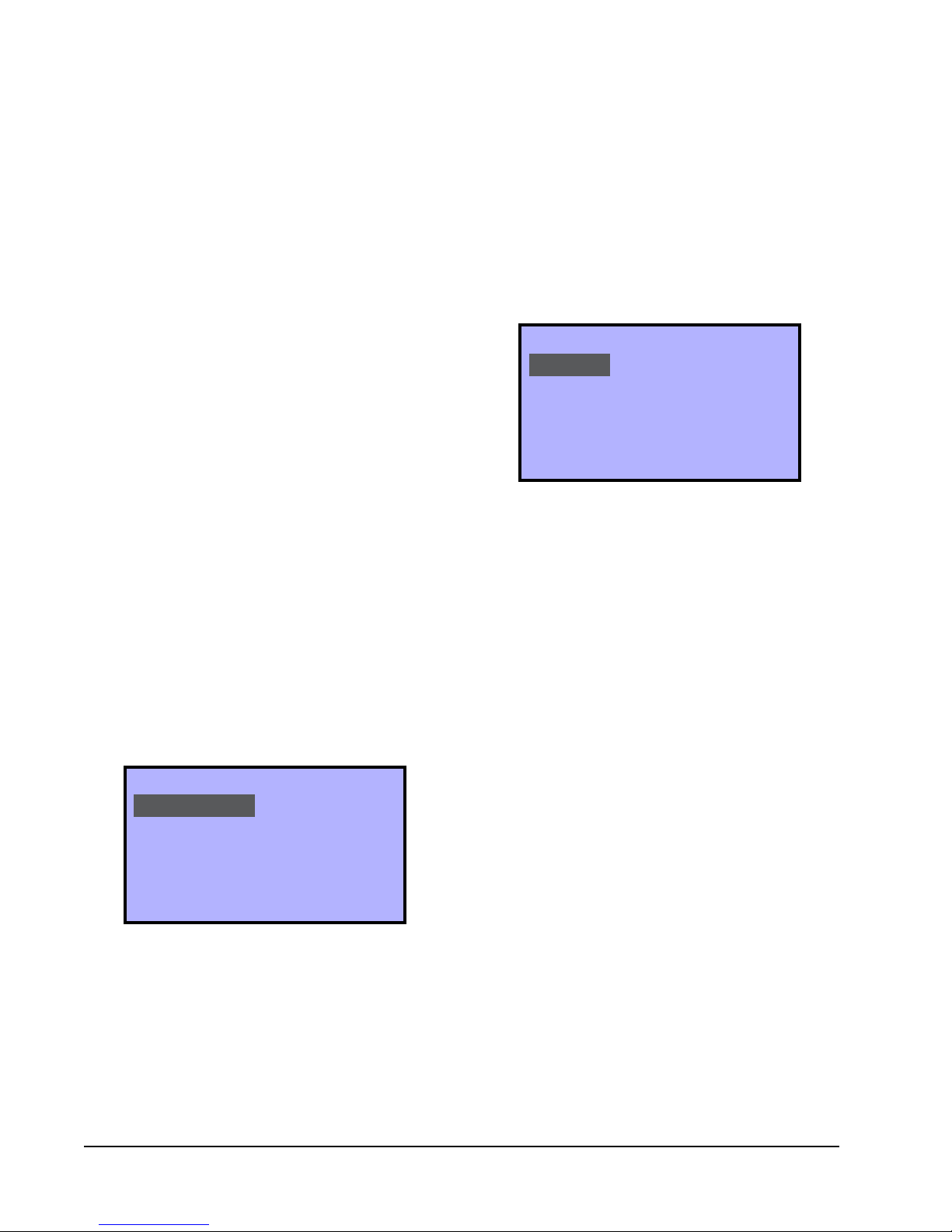
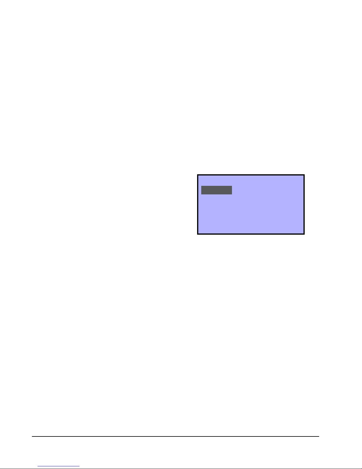
FIGURE 3
Application Menu
APPLICATION
DEGREES: ºF
UNIT_TYPE: HP
OPT: 2 STAGES
ADDITIONAL SETUP
5. Press ENTER button again to choose DEGREES.
NOTE:
The UNIT_TYPE category must be set to “NOT
CONFIGURED” before the controller will allow
the scale to be changed (see step 7 on page 6).
Manual 2100-684
Page 5 of 25
Page 6
6. Press UP or DOWN button to choose °F
(Fahrenheit) or °C (Celsius). Press ENTER to save
selection of scale.
NOTE: The change from F to C will not take effect
on the home screen until the 24VAC power is
cycled off and back on.
7. Press DOWN button to scroll to UNIT_TYPE. Press
ENTER button.
8. Press UP or DOWN button to choose from the
available system types (A/C, HP or Not Configured).
Press ENTER button to select/save appropriate
choice.
3. Press ENTER button to select/save appropriate
economizer option.
4. Press LEFT button to go back to ADDITIONAL
SETUP.
5. The indoor blower can be set for ON or AUTO
in either occupied or unoccupied conditions. To
access or change blower settings, press DOWN
button to scroll to FAN. Press ENTER button to
enter FAN SETUP (see Figure 5).
FIGURE 5
Fan Setup (Air Conditioner)
10. Press DOWN button to scroll to OPT. Press ENTER
button.
11. Press UP or DOWN button to choose from the
following available system stages:
• A/C – 1H/1C HP – 1 Stage
• A/C – 2H/2C HP – 2 Stages
• A/C – 1H/2C
• A/C – 2H/1C
NOTE: These are stages of compressor operation.
12. Press ENTER button to select/save appropriate
model stage.
13. Press DOWN button to scroll to ADDITIONAL
SETUP. Press ENTER button.
Air Conditioner Applications (see Figure 4)
NOTE: The following is for A/C applications. Heat
pump application information can be found in
the following section.
FIGURE 4
Additional Setup (Air Conditioner)
ADDITIONAL SETUP
VENTILATION
FAN
HUMIDITY
MOTION SENSOR
SENSORS
STAGING
Ventilation, Fan and Humidity Setup
1. Press ENTER button to enter VENTILATION menu.
2. Press ENTER button to highlight ECON options.
Press UP or DOWN button to choose from the
available economizer options:
• NONE = No economizer, or standard vent
package (ERV/CRV/MFAD)
• EN/DIS = Economizer in system
FAN SETUP
SPEEDS: CONSTANT SPEED
OFF DELAY (SECS): 0
UNOCC: AUTO
OCC: AUTO
6. Press DOWN button to scroll through selections;
adjust as necessary.
• Speeds: Constant speed (nonadjustable)
• Off Delay: “0” = System fan will run for
specified time after call ends; 0-600 seconds
in 30-second increments.
• Unocc: “ON” = System fan will run
continuously during all operational modes;
“AUTO” = System fan will operate during call
for cooling or heating, but will cycle off when
no compressor or no heating is needed (factory
default).
• Occ: “ON” = System fan will run continuously
during all operational modes; “AUTO” =
System fan will operate during call for
cooling or heating, but will cycle off when no
compressor or no heating is needed (factory
default).
7. Press ENTER button to save changes to FAN mode
selections.
8. Press LEFT button to go back to ADDITIONAL
SETUP.
9. Press DOWN button to scroll to HUMIDITY. Press
ENTER button to enter HUMIDITY SETUP.
10. Press DOWN button to scroll to
DEHUMIDIFICATION. Press ENTER button (see
Figure 6).
11. Press ENTER button again to highlight current
dehum choice (default is ENABLE).
Manual 2100-684
Page 6 of 25
Page 7
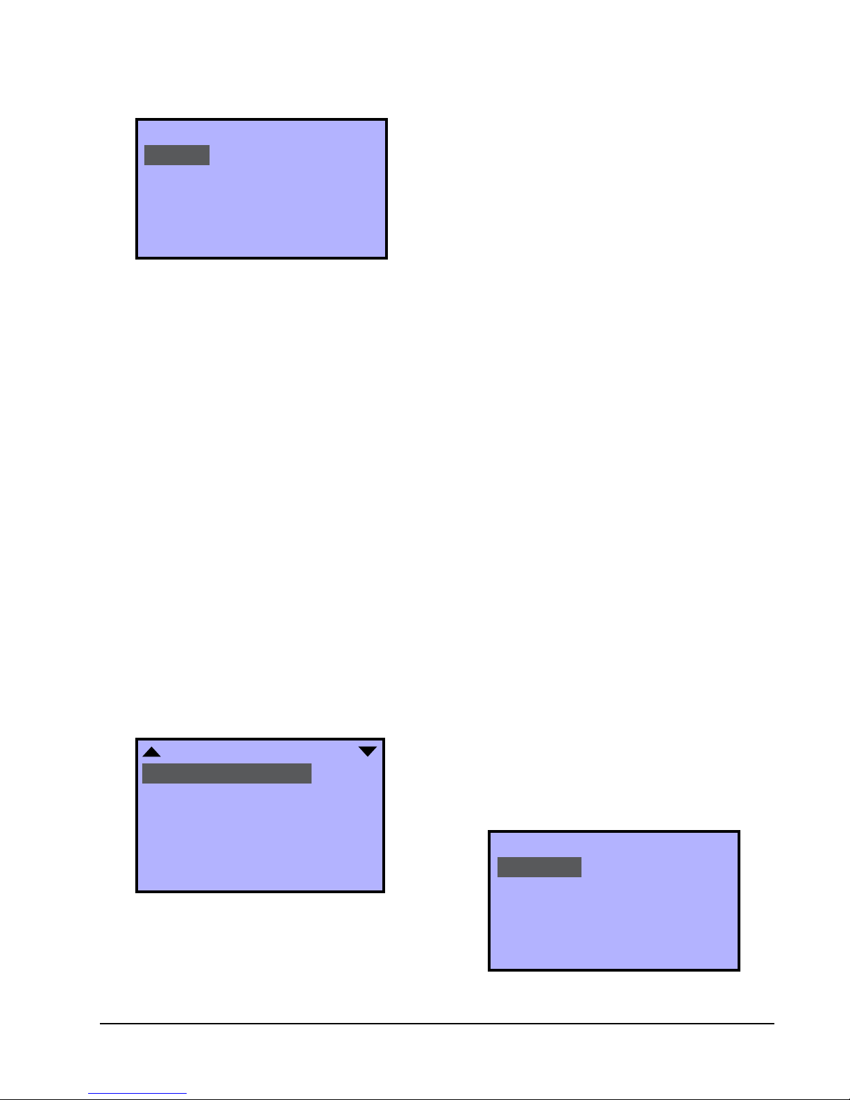
FIGURE 6
Dehumidification (Air Conditioner)
DEHUMIDIFICATION
DEHUM: ENABLE
ALLOW HEATING DEHUM: YES
DEHUM SETPT: 60%RH
DEHUM SPAN: 5%RH
12.
Press UP or DOWN button to toggle ENABLE/
DISABLE. Press ENTER button to select/save choice.
13. Press DOWN button to scroll through additional
DEHUMIDIFICATION screen choices:
• ALLOW HTG DEHUM = Allows
dehumidification in heating: YES/NO (default
is YES).
• DEHUM SETPT = Relative Humidity (RH)
setpoint: 45% RH to 80% RH, 1% increments
(default is 60%RH).
• DEHUM SPAN = Amount of RH% removal
allowed past setpoint: 5% to 10%, 1%
increments (default is 5%RH).
14. Press ENTER button to save changes.
15. Press LEFT button to return to the home screen.
Proceed to System Enable on page 9 to continue
the setup process.
Heat Pump Applications (see Figure 7)
NOTE: The following is for heat pump applications.
A/C application information can be found in
the previous section.
FIGURE 7
Additional Setup (Heat Pump)
1. Press RIGHT button to access Main Menu screen.
2. Press DOWN button to scroll to TECHNICIAN.
Press ENTER button.
3.
Controller will ask for password. Press UP and RIGHT
buttons to enter ‘BARD’. Press ENTER button.
4. In the TECHNICIAN menu screen, press ENTER
button to enter the APPLICATION menu.
5. Press DOWN button to scroll to ADDITIONAL
SETUP. Press ENTER button.
6. Press ENTER button again to choose AUX
ELECTRIC HEAT.
7. Press ENTER button again to highlight current AUX
HEAT choices (see Figure 8).
8. Press UP or DOWN button to scroll through AUX
HEAT screen choices:
• W/O LOCKOUT = Auxiliary heat will activate
regardless of compressor operation or outdoor
air temperature (factory default). If W/O
LOCKOUT is chosen, proceed to set delay-on
time (Step 9).
• COMP LOCKOUT = Compressor locks out
below the selected outdoor air temperature.
Requires optional Bard 8403-061 Outdoor Air
Temperature Sensor.
• NONE = No auxiliary strip heat; controller will
not energize W2. If NONE is chosen, press
LEFT button to return to the home screen.
9. Press DOWN button to highlight DELAY (MINS).
10. Press ENTER button to highlight default DELAY
minutes.
11. Press UP or DOWN button to select amount
of minutes desired to delay the electric heat
before activation: 10-120 minutes, in 10 minute
increments (factory default 15 minutes). Press
ENTER button to save choice.
ADDITIONAL SETUP
AUX ELECTRIC HEAT
VENTILATION
FAN
HUMIDITY
MOTION SENSOR
SENSORS
STAGING
Auxiliary Electric Heat Setup
If the heat pump selection is chosen, electric heat
must be configured. These steps do not apply to air
conditioners or other types of conventional heating. To
configure the auxiliary heat from the home screen:
12. Press LEFT button to return to ADDITIONAL
SETUP.
FIGURE 8
Aux Heat Setup
DEHUMIDIFICATION
AUX HEAT: W/O LOCKOUT
DELAY (MINS): 15
Manual 2100-684
Page 7 of 25
Page 8
If COMP LOCKOUT was chosen during the heat
strip configuration process, an optional outdoor
air temperature sensor will have to be installed/
configured to specifically set the temperature at which
the compressor will no longer be allowed to operate.
Refer to the latest version of CompleteStat Controller
Advanced Programming & Features 2100-685 to
configure the outdoor air temperature sensor.
To install Bard 8403-061 Outdoor Air Temperature
Sensor, attach the leads to terminals “OAT” and
“GND”. To set the compressor outdoor air temperature
limits from the home screen:
1. Press RIGHT button to access Main Menu screen.
2. Press DOWN button to scroll to TECHNICIAN.
Press ENTER button.
3. In the TECHNICIAN menu screen, press UP or
DOWN button to scroll to LIMITS. Press ENTER
button.
4. Press DOWN button to scroll to COMP OAT CLG
LOW. Press ENTER button.
5. Press UP or DOWN button to select outdoor air
temperature for compressor lockout (factory default
0ºF). Press ENTER to save choice.
6. Press LEFT button to return to TECHNICIAN menu.
• Off Delay: “0” = System fan will run for
specified time after call ends; 0-600 seconds
in 30-second increments.
•
• Occ: “ON” = System fan will run continuously
9. Press ENTER button to save changes to FAN
Unocc: “ON” = System fan will run continuously
during all operational modes; “AUTO” = System
fan will operate during call for cooling or
heating, but will cycle off when no compressor
or no heating is needed (factory default).
during all operational modes; “AUTO” =
System fan will operate during call for
cooling or heating, but will cycle off when no
compressor or no heating is needed (factory
default).
SETUP selections.
FIGURE 9
Fan Setup (Heat Pump)
FAN SETUP
SPEEDS: CONSTANT SPEED
OFF DELAY (SECS): 0
UNOCC: AUTO
OCC: AUTO
Ventilation, Fan and Humidity Setup
1. In the TECHNICIAN menu screen, press ENTER
button to enter the APPLICATION menu.
2. Press DOWN button to scroll to ADDITIONAL
SETUP. Press ENTER button.
3. Press DOWN button to scroll to VENTILATION.
Press ENTER button.
4. Press UP or DOWN button to choose from the
available economizer options:
• NONE = No economizer, or standard vent
package (ERV/CRV/MFAD). This is the factory
default.
• EN/DIS = Economizer in system
5. Press ENTER button to select/save appropriate
economizer option.
6. Press LEFT button to go back to ADDITIONAL
SETUP.
7. The indoor blower can be set for ON or AUTO
in either occupied or unoccupied conditions. To
access or change blower settings, press DOWN
button to scroll to FAN. Press ENTER button to
enter FAN SETUP (see Figure 9).
8. Press DOWN button to scroll through selections;
adjust as necessary.
• Speeds: Constant speed (nonadjustable)
10. Press LEFT button to go back to ADDITIONAL
SETUP.
11. Press DOWN button to scroll to HUMIDITY. Press
ENTER button to enter HUMIDITY SETUP.
12. Press ENTER button again to choose
DEHUMIDIFICATION (see Figure 10).
13. Press ENTER button again to highlight current
dehum choice (default is ENABLE).
14. Press UP or DOWN button to toggle ENABLE/
DISABLE. Press ENTER button to select/save
choice.
15. Press DOWN button to scroll through additional
DEHUMIDIFICATION screen choices:
• ALLOW HTG DEHUM = Allows
dehumidification in heating as well as cooling:
YES/NO (default is YES).
• DEHUM SETPT = Relative Humidity (RH)
setpoint: 45% RH to 80% RH, 1% increments
(default is 60%RH).
• DEHUM SPAN = Amount of RH% removal
allowed past setpoint: 5% to 10%, 1%
increments (default is 5%RH).
16. Press ENTER button to save changes.
Manual 2100-684
Page 8 of 25
Page 9

FIGURE 10
Dehumidification (Heat Pump)
• EMER HT = HP mode only.
• OFF = HVAC system is inactive.
DEHUMIDIFICATION
DEHUM: ENABLE
ALLOW HEATING DEHUM: YES
DEHUM SETPT: 60%RH
DEHUM SPAN: 5%RH
Reversing Valve Setup
1. Press LEFT button two (2) times to return to
ADDITIONAL SETUP.
2. Press UP or DOWN buttons to scroll to VALVE (see
Figure 11). NOTE: VALVE does not show up on
first screen. Continuing to press the UP or DOWN
button will display VALVE.
3. Press ENTER button to highlight choice of ACTIVE
HTG or ACTIVE CLG. Press UP or DOWN button to
toggle between the choices. Press ENTER button to
save choice.
4. Press LEFT button to return to the home screen.
• COOLING = System is in “Cooling-Only” mode.
HVAC system will cycle cooling in reference
to cooling setpoint only. Unit will not activate
heating sequence.
• HEATING = System is in “Heating-Only” mode.
HVAC system will cycle heating in reference
to heating setpoint only. Unit will not activate
cooling sequence.
4. Press ENTER button to save choice.
5. Press LEFT button to return to the home screen.
FIGURE 12
System Enable
SYSTEM
SYSTEM ENABLE: AUTO
OCCUPANCY: SCHEDULE
OCC OVRIDE (MINS): 240
SCHEDULE
FIGURE 11
Additional Setup (Heat Pump)
ADDITIONAL SETUP
VENTILATION
FAN
HUMIDITY
MOTION SENSOR
SENSORS
STAGING
VALVE
System Enable
To enable heating or cooling from the home screen:
1. Press RIGHT button to access the Main Menu
screen.
2. Press ENTER button to enter the SYSTEM menu
(see Figure 12).
3. Press ENTER button to choose from available
SYSTEM ENABLE options (use UP or DOWN
buttons to scroll through choices):
• AUTO (factory default) = System is in “Auto-
Changeover” mode. HVAC system will cycle
heating and cooling automatically to stay
within preset heating and cooling setpoints.
Setpoints
To access setpoints from the home screen:
1. Press RIGHT button to access the Main Menu
screen.
2. Press DOWN button to scroll to SETPOINTS. Press
ENTER button (see Figure 13). Factory default
values are shown in the figure.
FIGURE 13
Setpoints
SETPOINTS
COOL SETPT: 74°F
COOL SETBACK: 80°F
HEAT SETPT: 70°F
HEAT SETBACK: 64°F
HUMIDITY
CO2 SETPT (PPM): 1200
CO2 SPAN (PPM): 200
3. Press ENTER button to select COOL SETPT.
4. Press UP or DOWN buttons to enter appropriate
cooling setpoint. Press ENTER button to save new
cooling setpoint.
5. Press DOWN button to scroll to HEAT SETPT. Press
ENTER button.
Manual 2100-684
Page 9 of 25
Page 10

6. Press UP or DOWN buttons to enter appropriate
heating setpoint. Press ENTER button to save new
heating setpoint.
7. Follow the steps provided above to adjust cooling
and heating setback temperatures, dehum setpoint
and span, and CO
setpoint and span of control in
2
parts per million (if available).
8. Press LEFT button to return to the home screen.
NOTE: The controller will not allow heating/cooling
setpoints to contradict one another, or to be
within a degree of conflicting operation.
NOTE: Any system startup with indoor ambient
temperatures lower than 56°F or above 86°F,
or humidity higher than 65%, will experience
an internal Low Temperature or High
Temperature alarm. This will not affect normal
operation and can be cleared easily.
Bard CompleteStat should be operational at this point.
For further controller enhancement or operation detail,
please consult the latest edition of CompleteStat
Advanced Programming & Features 2100-685.
Manual 2100-684
Page 10 of 25
Page 11
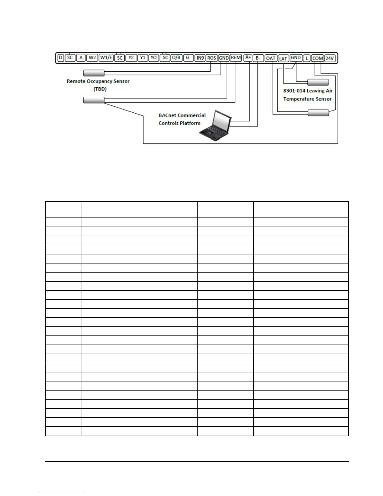
FIGURE 14
CompleteStat Terminal Descriptors and Optional Inputs
8403-062 Indoor Remote
Air Temperature Sensor
8403-061 Outdoor Air
Temperature Sensor
NOTE: Use twisted shielded pair for optional outdoor and indoor air sensors. Connect shield (drain) to 24V
common.
TABLE 1
Controller Connections
Terminal Function Type Form
D Dehumidification Output 24VAC SPST Relay
SC Not Used 24VAC Hot
A Ventilation Call Output 24VAC SPST Relay
nd
W2 2
W1/E 1
Stage Heating Output 24VAC SPST Relay
st
Stage Heating/Emergency Heat Output 24VAC SPST Relay
SC Not Used 24VAC Hot
Y2 2nd Stage Compressor Output 24VAC SPST Relay
Y1 1st Stage Compressor Output 24VAC SPST Relay
Y0 Economizer Output 24VAC SPST Relay
SC Not Used 24VAC Hot
O/B Reversing Valve Output 24VAC SPST Relay
G Indoor Blower Output 24VAC SPST Relay
IN9 Not Used
ROS Remote Occupancy Sensor Input Dry Contact (Input to GND)
GND Sensor Ground
REM Remote Temperature Sensor Input 10K Type II Thermistor
+B Communications
-A Communications
OAT Outdoor Air Temperature Sensor Input 10K Type II Thermistor
LAT Leaving Air Temperature Sensor Input 10K Type II Thermistor
GND Sensor Ground
L Lockout Alarm Input 24VAC
Com 24VAC Common Power
24V 24VAC Hot
Power
Manual 2100-684
Page 11 of 25
Page 12

SEQUENCE OF OPERATION
TABLE 2
Conventional 1H/1C, 2H/1C, 1H/2C or 2H/2C without Economizer
Operation G Y/O Y1 Y2 W1/E W2 O/B D A
Fan Only X
st
Stage Cooling X X
1
nd
Stage Cooling (if employed) X X X
2
st
Stage Heating X X
1
nd
Stage Heating (if employed) X X X
2
Dehumidification X
Ventilation
1
CS9B(E)-THOCA (CO2 Sensing Capability) models will activate both G and A terminals upon a ventilation call;
1
however, the CS9B(E)-THOA (Non-CO
for the indoor blower, whether through space conditioning or through constant fan operation.
Conventional 1H/1C, 2H/1C, 1H/2C or 2H/2C with Economizer
1
X
Sensing) models will activate the A terminal only if there is an existing call
2
TABLE 3
X
Operation G Y/O Y1 Y2 W1/E W2 O/B D A
Fan Only X
st
Stage Cooling (Economizer) X X
1
nd
Stage Cooling X X X
2
rd
Stage Cooling (if employed) X X X X
3
st
Stage Heating X X
1
nd
Stage Heating (if employed) X X X
2
Dehumidification X
Ventilation
1
CS9B(E)-THOCA (CO2 Sensing Capability) models will activate both G and A terminals upon a ventilation call;
1
however, the CS9B(E)-THOA (Non-CO
1
X
Sensing) models will activate the A terminal only if there is an existing call
2
for the indoor blower, whether through space conditioning or through constant fan operation.
X
Manual 2100-684
Page 12 of 25
Page 13

TABLE 4
Single Stage Heat Pump without Economizer
Operation G Y/O Y1 Y2 W1/E W2 O/B D A
Fan Only X
st
Stage Cooling X X
1
st
Stage Heating X X X X
1
2nd Stage Heating X X X X
Emergency Heat X X X
3
3
2
2
X
Dehumidification X
Ventilation
1
CS9B(E)-THOCA (CO2 Sensing Capability) models will activate both G and A terminals upon a ventilation call;
however, the CS9B(E)-THOA (Non-CO
1
2
1
X
Sensing) models will activate the A terminal only if there is an existing call
for the indoor blower, whether through space conditioning or through constant fan operation.
2
CompleteStat controller can be configured to energize reversing valve in cooling (see System Selection on page 5).
3
Electric heat must be configured for a heat pump application (see Auxiliary Electric Heat Setup on page 7).
TABLE 5
Two Stage Heat Pump without Economizer
X
Operation G Y/O Y1 Y2 W1/E W2 O/B D A
Fan Only X
st
Stage Cooling X X
1
nd
Stage Cooling X X X
2
st
Stage Heating X X X X
1
2nd Stage Heating X X X X X
3rd Stage Heating X X X X X
Emergency Heat X X X
3
3
2
2
2
X
Dehumidification X
Ventilation
1
CS9B(E)-THOCA (CO2 Sensing Capability) models will activate both G and A terminals upon a ventilation call;
however, the CS9B(E)-THOA (Non-CO
1
2
1
X
Sensing) models will activate the A terminal only if there is an existing call
for the indoor blower, whether through space conditioning or through constant fan operation.
2
CompleteStat controller can be configured to energize reversing valve in cooling (see System Selection on page 5).
3
Electric heat must be configured for a heat pump application (see Auxiliary Electric Heat Setup on page 7).
X
Manual 2100-684
Page 13 of 25
Page 14

SEQUENCE OF OPERATION (CONT.)
TABLE 6
Single Stage Heat Pump with Economizer
Operation G Y/O Y1 Y2 W1/E W2 O/B D A
Fan Only X
st
Stage Cooling X X X
1
nd
Stage Cooling X X X
2
st
Stage Heating X X X X
1
2nd Stage Heating X X X X
Emergency Heat X X X
3
3
Dehumidification X
Ventilation
1
CS9B(E)-THOCA (CO2 Sensing Capability) models will activate both G and A terminals upon a ventilation call;
1
however, the CS9B(E)-THOA (Non-CO
1
X
Sensing) models will activate the A terminal only if there is an existing call
2
for the indoor blower, whether through space conditioning or through constant fan operation.
2
CompleteStat controller can be configured to energize reversing valve in cooling (see System Selection on page 5).
3
Electric heat must be configured for a heat pump application (see Auxiliary Electric Heat Setup on page 7).
2
2
X
X
TABLE 7
Two Stage Heat Pump with Economizer
Operation G Y/O Y1 Y2 W1/E W2 O/B D A
Fan Only X
st
Stage Cooling X X X
1
nd
Stage Cooling X X X
2
rd
Stage Cooling X X X X
3
st
Stage Heating X X X X
1
2nd Stage Heating X X X X X
3rd Stage Heating X X X X X
Emergency Heat X X X
3
3
2
2
2
X
Dehumidification X
Ventilation
1
CS9B(E)-THOCA (CO2 Sensing Capability) models will activate both G and A terminals upon a ventilation call;
1
however, the CS9B(E)-THOA (Non-CO
1
X
Sensing) models will activate the A terminal only if there is an existing call
2
for the indoor blower, whether through space conditioning or through constant fan operation.
2
CompleteStat controller can be configured to energize reversing valve in cooling (see System Selection on page 5).
3
Electric heat must be configured for a heat pump application (see Auxiliary Electric Heat Setup on page 7).
X
Manual 2100-684
Page 14 of 25
Page 15

TABLE 8
Wiring Diagram Index
WIRING DIAGRAMS
No.
Unit
Type
CompleteStat
Model
CS9B(E)-
1
CompleteStat
System Type
System
Stages
Setting
Economizer
Setting
1 A/C THOA, THOCA A/C 2H/2C None
2 A/C THOA, THOCA A/C 2H/2C EN/DIS
3 A/C THOA, THOCA A/C 2H/2C EN/DIS
4 HP THOA, THOCA HP 1 Stage None
5 HP THOA, THOCA HP 2 Stage None
6 HP THOA, THOCA HP 1 Stage EN/DIS
7 HP THOA, THOCA HP 2 Stage EN/DIS
8 Gas/Electric THOA, THOCA A/C 1H/1C None
9 Gas/Electric THOA, THOCA A/C 1H/2C None
®
10 I-TEC
11 I-TEC
12 I-TEC
HP THOA, THOCA HP 2 Stage None
®
HP THOA, THOCA HP 2 Stage None
®
HP THOA HP 2 Stage None
13 Q-TECTM QA THOA, THOCA A/C 2H/1C None
TM
14 Q-TEC
QH THOA, THOCA HP 1 Stage None
15 QWS THOA, THOCA HP 2 Stage None
16 C**H THOA, THOCA HP 2 Stage EN/DIS
Use with
Bard Units
1 or 2-Stage A/C w/ or
w/o Elec. Heat
1-Stage A/C with or
w/o Elec. Heat
2-Stage A/C with or
w/o Elec. Heat
1-Stage HP with or
w/o Elec. Heat
2-Stage HP with or
w/o Elec. Heat
1-Stage HP with or
w/o Elec. Heat
2-Stage HP with or
w/o Elec. Heat
1-Stage A/C with Gas
Heat
2-Stage A/C with Gas
Heat
2-Stage HP with or
w/o Elec. Heat
2-Stage HP with or
w/o Elec. Heat
2-Stage HP with or
w/o Elec. Heat
1-Stage A/C with or
w/o Elec. Heat
1-Stage HP with or
w/o Elec. Heat
2-Stage Geo/Water
Source HP
2-Stage HP with or
w/o Elec. Heat
Vent
Ventilation System
Control
Type
CRV, ERV, MFAD On/Off
ECONWM Factory "T"
or "W" Economizer w/
On/Off
JADE W7220 Control
ECONWM Factory "T"
or "W" Economizer w/
On/Off
JADE W7220 Control
CRV, ERV, MFAD On/Off
CRV, ERV, MFAD On/Off
ECONWM Factory "T"
or "W" Economizer w/
On/Off
JADE W7220 Control
ECONWM Factory "T"
or "W" Economizer w/
On/Off
JADE W7220 Control
CRV, ERV, MFAD On/Off
CRV, ERV, MFAD On/Off
None On/Off
CRV On/Off
Modulating ERV, use
–THOA plus 8403067 CO
controller
2
Mod.
CRV, ERV On/Off
CRV, ERV On/Off
CRV, ERV On/Off
ECONCH Factory
“S” w/JADE W7220
On/Off
Control
2
1
Either THOA or THOCA version can be used. For THOA, vent output “A” limits vent operation to occupied periods. For THOCA, vent
output “A” operates vent based on CO2 level.
2
Modulating
Manual 2100-684
Page 15 of 25
Page 16

WIRING DIAGRAMS
WIRING DIAGRAM 1
Conventional 1H/1C, 1H/2C, 2H/1C or 2H/2C, with or without Dehumidification and Ventilation, No Economizer
CompleteStat
6
7
Field-installed wires and jumpers
1
2
3
4
Wire for dehumidification units only
Optional wire only for 2 stage heating
(15kW or more)
Remove jumper for 2 stage heat
(15kW or more)
Wire only for 2 stage cooling, if available
Factory-installed wires and jumpers
5
6
7
Wire not used on MFAD ventilation option
W**A2 units use “D” terminal
W**A1 units use “3” terminal
For fire-smoke/emergency shutdown, remove
factory jumper and connect NC contacts from
field-installed device to terminals “RT” and “R”.
Only offered on single stage W**A2 units.
TM
Manual 2100-684
Page 16 of 25
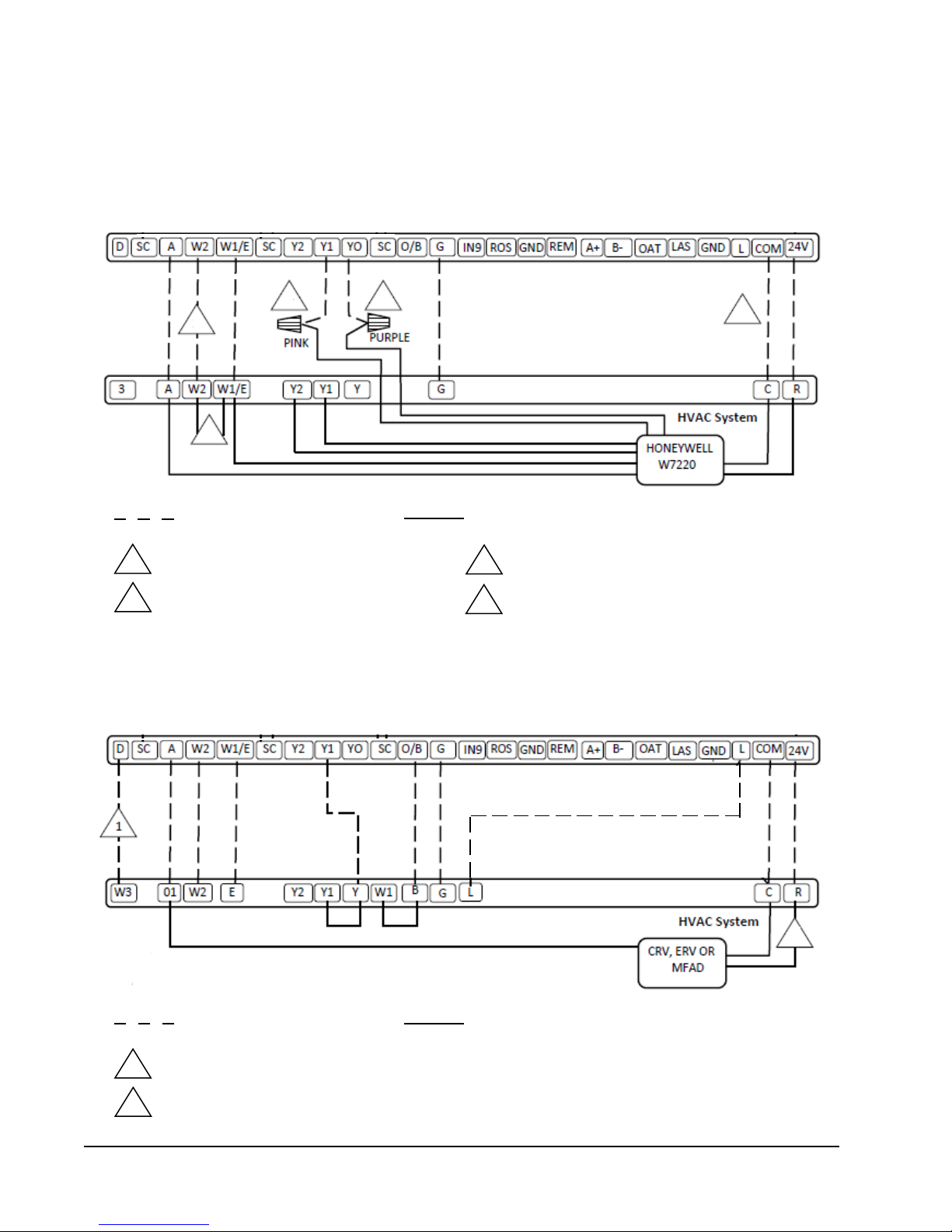
Page 17

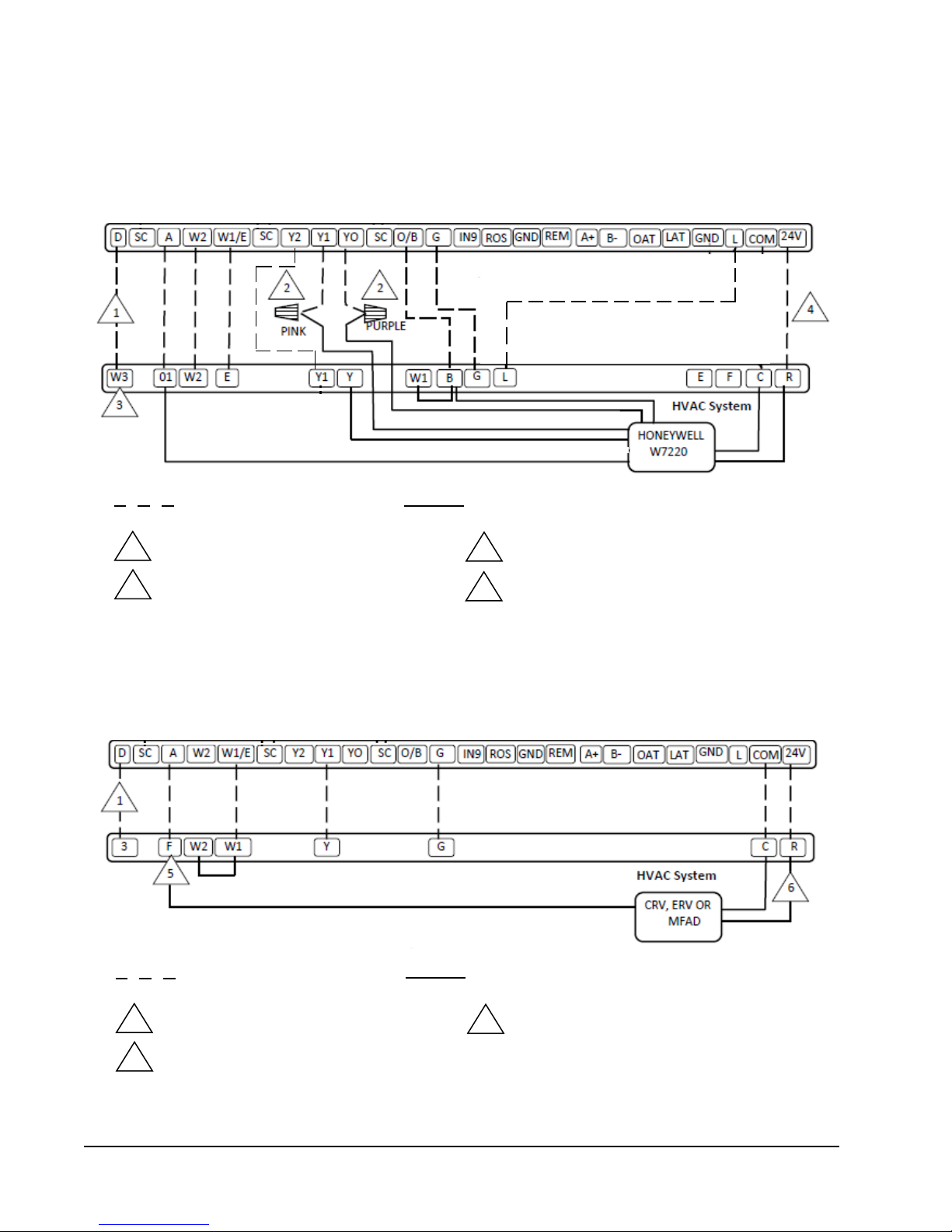
WIRING DIAGRAM 2
Conventional 1H/1C or 2H/1C with Honeywell W7220 JadeTM Control Economizer,
with or without Dehumidification
CompleteStat
TM
JADE
Field-installed wires and jumpers
1
2
3
4
Wire for dehumidification units only
Optional wire only for 2 stage heating
(15kW or more)
Remove jumper for 2 stage heat
(15kW or more)
CompleteStat programmed for damper/
economizer: Enable/Disable
Factory-installed wires and jumpers
5
6
W**A2 units use “D” terminal
W**A1 units use “3” terminal
For fire-smoke/emergency shutdown, remove
factory jumper and connect NC contacts from
field-installed device to terminals “RT” and “R”.
Only offered on single stage W**A2 units.
TM
Manual 2100-684
Page 17 of 25
Page 18
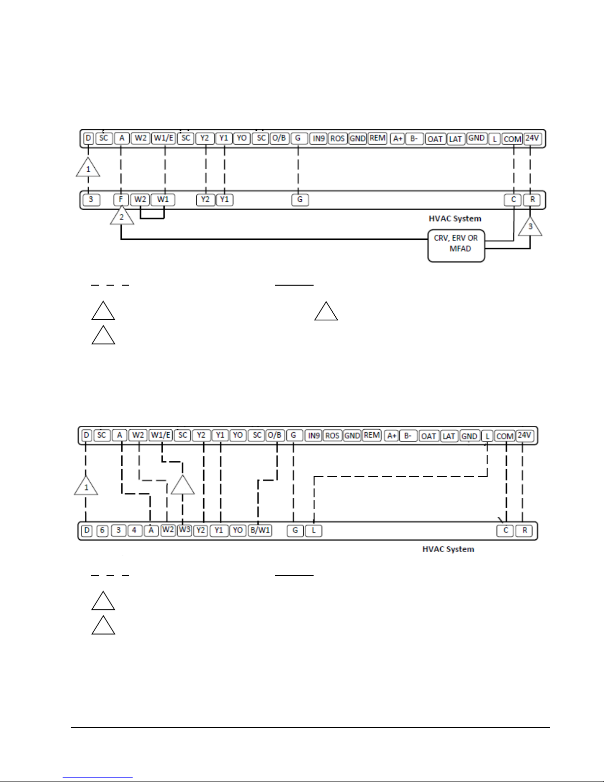
WIRING DIAGRAMS (CONT.)
Conventional 1H/2C or 2H/2C with Honeywell W7220 JadeTM Control Economizer,
No Dehumidification, 2 Stage Compressor Only
WIRING DIAGRAM 3
CompleteStat
TM
3 3
1
2
TM
JADE
Field-installed wires and jumpers
1
2
Optional wire only for 2 stage heating
(15kW or more)
Remove jumper for 2 stage heat
(15kW or more)
Factory-installed wires and jumpers
3
4
Field-installed wire nut
CompleteStat programmed for damper/
economizer: Enable/Disable
4
WIRING DIAGRAM 4
Heat Pump 2H/1C or 3H/1C, with or without Dehumidification and Ventilation, no Economizer
CompleteStat
TM
Field-installed wires and jumpers
1
2
Wire for dehumidification units only
Wire not used on MFAD ventilation option
Manual 2100-684
Page 18 of 25
2
Factory-installed wires and jumpers
Page 19

WIRING DIAGRAM 5
Heat Pump 2 Stage, with or without Dehumidification and Ventilation
CompleteStat
Field-installed wires and jumpers
1
2
Wire for dehumidification units only
CH*S Series heat pumps use “DH”
dehumidification terminal
Factory-installed wires and jumpers
3
Wire not used on MFAD ventilation option
TM
WIRING DIAGRAM 6
Heat Pump 1 Stage with Honeywell W7220 JadeTM Control Economizer, with or without Dehumidification
CompleteStat
TM
JADE
Field-installed wires and jumpers
1
2
Wire for dehumidification units only
Field-installed wire nut on 9 EER W**A2, A1 units. For W**AA units, consult unit installation instructions.
Factory-installed wires and jumpers
TM
3
CompleteStat programmed for damper/economizer: Enable/Disable
Manual 2100-684
Page 19 of 25
Page 20
WIRING DIAGRAMS (CONT.)
WIRING DIAGRAM 7
Heat Pump 2 Stage with Honeywell W7220 JadeTM Control Economizer, with or without Dehumidification
CompleteStat
TM
JADE
Field-installed wires and jumpers
1
2
Wire for dehumidification units only
Field-installed wire nut
Factory-installed wires and jumpers
3
4
CH*S Series heat pumps use “DH“
dehumidification terminal
CompleteStat programmed for damper/
economizer: Enable/Disable
TM
WIRING DIAGRAM 8
Gas/Electric 1H/1C, with or without Dehumidification and Ventilation, No Economizer
Field-installed wires and jumpers
1
2
Wire for dehumidification units only
W**G Series uses “A” terminal for
ventilation
Factory-installed wires and jumpers
3
Wire not used on MFAD ventilation option
CompleteStat
TM
Manual 2100-684
Page 20 of 25
Page 21
WIRING DIAGRAM 9
Gas/Electric 1H/2C, with or without Dehumidification and Ventilation, No Economizer
CompleteStat
Field-installed wires and jumpers
1
2
Wire for dehumidification units only
W**G Series uses “A” terminal for
ventilation
Factory-installed wires and jumpers
3
Wire not used on MFAD ventilation option
TM
WIRING DIAGRAM 10
I-TEC 2 Stage Heat Pump Series with No Ventilation
CompleteStat
2
Field-installed wires and jumpers
1
2
Wire for dehumidification units only
Wire not needed if auxiliary heat strip
is 10 kW or less
Factory-installed wires and jumpers
TM
Manual 2100-684
Page 21 of 25
Page 22

WIRING DIAGRAMS (CONT.)
I-TEC 2 Stage Heat Pump Series with CRV Ventilation Package
WIRING DIAGRAM 11
CompleteStat
Field-installed wires and jumpers
2
1
Wire for dehumidification units only
Wire not needed if auxiliary heat strip
is 10 kW or less
Factory-installed wires and jumpers
TM
Manual 2100-684
Page 22 of 25
Page 23

WIRING DIAGRAM 12
I-TEC 2 Stage Heat Pump Series with ERV Ventilation Package and 8403-067 CO2 Detector (Fully Modulating)
CompleteStat
TM
Field-installed wires and jumpers
1
2
Wire for dehumidification units only
Wire not needed if auxiliary heat strip
is 10 kW or less
Factory-installed wires and jumpers
3
8403-067 to be used with non-CO
sensing CompleteStat
2
Manual 2100-684
Page 23 of 25
Page 24
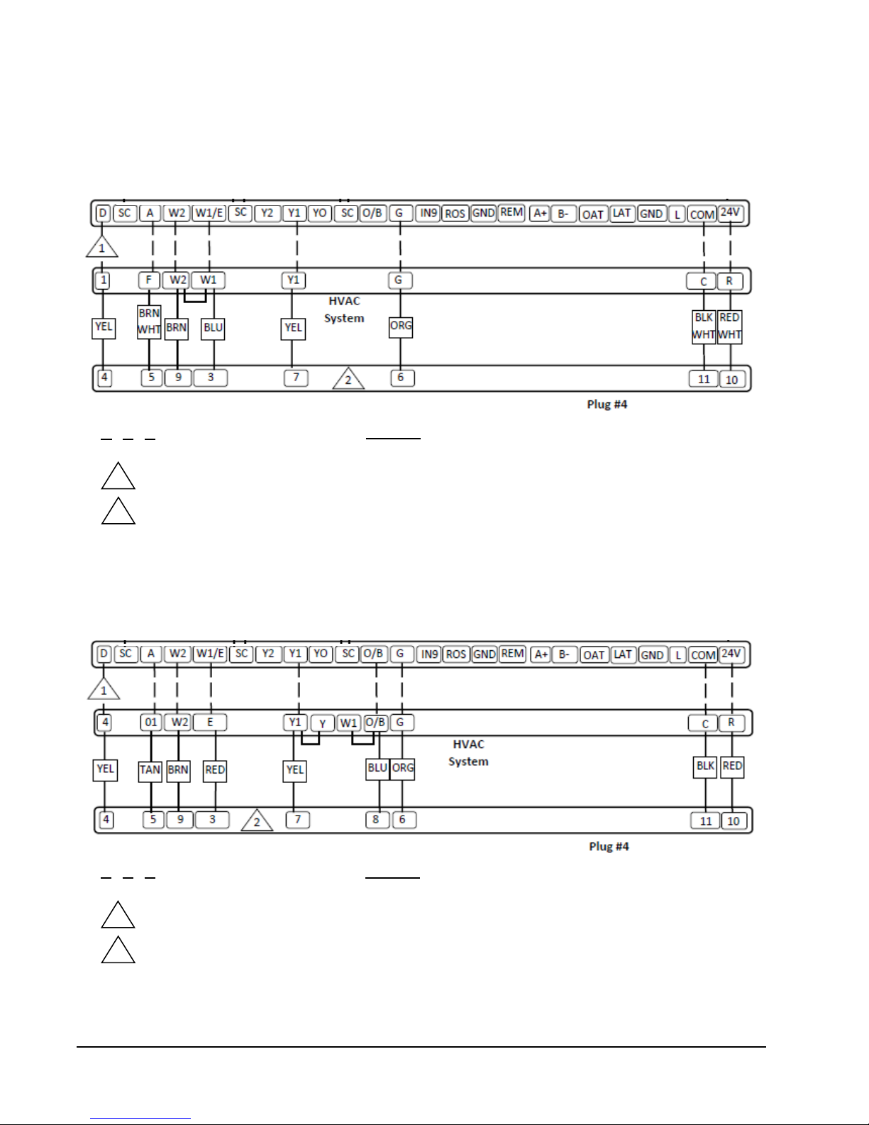
WIRING DIAGRAMS (CONT.)
WIRING DIAGRAM 13
Q-TEC QA**/Q**A Series 1 Stage Air Conditioner with or without Dehumidification and Ventilation, No Economizer
CompleteStat
Field-installed wires and jumpers Factory-installed wires and jumpers
1
2
Wire for dehumidification units only
Q Series with factory-installed thermostat had no terminal board and were wired directly from Plug #4.
Use provided colors to wire CompleteStat.
WIRING DIAGRAM 14
Q-TEC QH**/Q**H Series 1 Stage Heat Pump with or without Dehumidification and Ventilation
TM
CompleteStat
Field-installed wires and jumpers
1
2
Wire for dehumidification units only
Q Series with factory-installed thermostat had no terminal board and were wired directly from Plug #4.
Use provided colors to wire CompleteStat.
Factory-installed wires and jumpers
TM
Manual 2100-684
Page 24 of 25
Page 25

1
HVAC System
PINK
PURPLE
1
W3
01
W2 E Y1 G C R Y E F
W1
B
L
HONEYWELL
BLK
RED
WHT
BLU
YEL
ORG
(USE ENCLOSED RELAY)
D
SC A W2
W1/E
SC
Y2
Y1
YO
O/B
G
IN9
ROS
GND
REM
OAT
LAS
SC
A+
B-
GND
L
COM
24V
CompleteStatTM
Wiring Diagram 22: C**H Heat Pump 2-Stage, with Honeywell W7220 JadeTM Control Economizer, with or w/o dehum.
PURPLE
PINK
BLUE
YELLOW
ORANGE
BLACK
RED
WIRING DIAGRAM 15
QW*S Series 2 Stage Heat Pump with or without Dehumidification and Ventilation
CompleteStat
Field-installed wires and jumpers Factory-installed wires and jumpers
1
2
Wire for dehumidification units only
Q Series with factory-installed thermostat had no terminal board and were wired directly from Plug #4.
Use provided colors to wire CompleteStat.
TM
WIRING DIAGRAM 16
C**H Heat Pump 2 Stage with Honeywell W7220 Jade
TM
Control Economizer, with or without Dehumidification
CompleteStat
TM
1
22
Field-installed wires and jumpers
1
2
Wire for dehumidification units only
Field-Installed wire nuts
Factory-installed wires and jumpers
W7220
JADE
TM
Manual 2100-684
Page 25 of 25
 Loading...