

Page 1
INSTALLATION INSTRUCTIONS
CMA-32
Low Ambient Fan Cycling Control
The CMA-32 is a field-installable low ambient fan cycling
control kit.
for use on R-410A refrigerant systems.
The
• 7960-778 Installation Instructions
• 8607-017 Terminal Block
• 1012-066 Screw (1)
• 8612-027 230V Head Pressure Control
• 1804-0520 Extension Tube Assembly
• 8611-115 Plug Assembly
• 113-353 Mounting Bracket
• 1012-065 Screws (2)
The CMA-32 kit is for use with Bard models W42A2D,
W48A2D and W60A2D wall-mount air conditioners.
This fan cycling low ambient control is only
CMA-32
kit consists of:
INSTALLATION
Disconnect all power to wall-mount unit. Remove outer
and inner control panel covers and right side condenser
inlet grille. Circled numbers provided in Figure 1
on page 2 correspond to the following installation
steps. Dashed lines indicate where a wire has been
disconnected from the terminal.
1. Mount 8607-017 terminal block to unit control
panel with 1012-066 screw as shown in Figure 1.
2. Disconnect black high voltage outdoor motor
lead from compressor contactor and reconnect to
terminal block.
3. Remove the upper service port cap from the liquid
line. Install the low ambient control on the liquid
line by screwing it onto the service port as shown
in Figure 2 on page 3. Use wrenches to make the
connection snug and check for leaks.
4.
Route low ambient control wires up through the
bushing in the bottom of the control panel. Replace
sealing compound after routing wires through the
bushing. Route the wires through the wire holders
in the control panel as shown in Figure 1.
5. Connect the low ambient control wires between the
terminal block and T2 of the compressor contactor
(see Figure 1).
6. Recheck wiring by referring to Figure 1. Turn on
power to unit. Check for proper operation of the
unit by energizing in cooling mode (first or second
stage). The compressor should start—except when
equipped with economizer and enthalpy control is
energizing “free cooling” mode. Energizing “Y2”
will override the enthalpy control allowing the
mechanical cooling to operate. Run the unit for at
least 5 minutes. The condensor fan motor should
not run until the liquid pressure has reached 350
PSI. Should the liquid pressure fall below 225 PSI
while running, the condensor fan motor will deenergize until the head pressure builds to 350 PSI.
7. Apply “This unit is equipped with CMA-32 control
module” label to the inside of the inner control
panel cover above the unit wiring diagram.
8. Replace the right side condenser inlet grille
and inner and outer control panel covers. This
completes the installation.
Bard Manufacturing Company, Inc.
Bryan, Ohio 43506
www.bardhvac.com
Manual: 7960-778
Supersedes: NEW
Date: 5-24-16
Page 1 of 4
Page 2
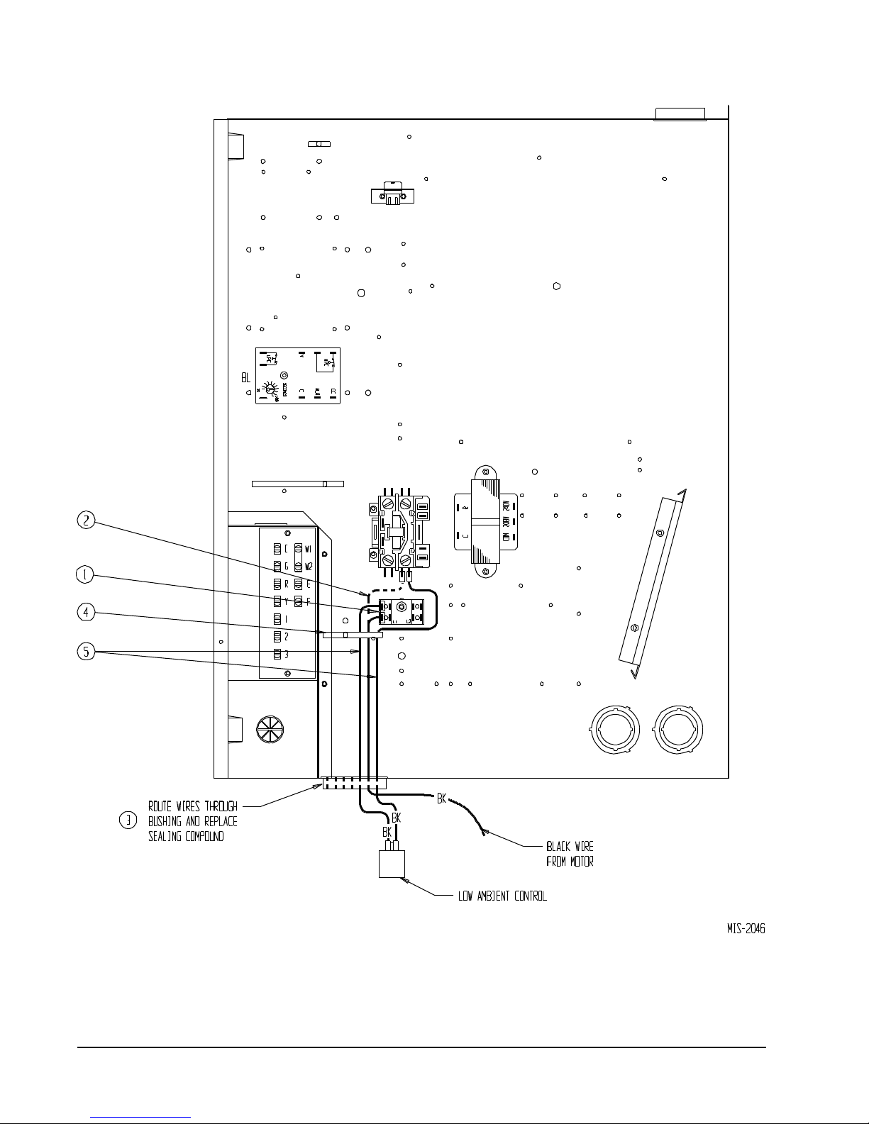
FIGURE 1
Manual 7960-778
Page 2 of 4
Page 3

FIGURE 2
DEHUM INLET TUBE
DEHUM OUTLET TUBE
TUBING GROMMET
LIQUID LINE ASSEMBLY
SUCTION LINE
FIGURE 2
CONNECT TO SERVICE PORT AS SHOWN
ROUTE WIRE THROUGH
BUSHING INTO
CONTROL PANEL
DEHUMIDIFICATION
VALVE ASSEMBLY
ATTACH BRACKET
USING (2) 1012-085
SUPPLIED SCREWS
UNDER BASE
MIS-3842
Manual 7960-778
Page 3 of 4
Page 4

FIGURE 3
Manual 7960-778
Page 4 of 4
 Loading...