

Page 1

OPERATION INSTRUCTIONS
ENERGY RECOVERY VENTILATOR
WITH EXHAUST
Model:
For Use With Bard
2 Through 5 Ton
920-0074
QWSERV
QW*S Series
Bard Manufacturing Company, Inc.
Bryan, Ohio 43506
Since 1914...Moving ahead, just as planned.
Manual: 2100-533A
Supersedes: 2100-533
File: Volume II, Tab 14
Date: 12-08-10
Manual 2100-533A
Page 1 of 12
Page 2

CONTENTS
Electrical Specifications .......................................... 3
General Description of ERV ................................... 3
Control Requirements ............................................ 3
Recommended Control Sequences ....................... 4
Control Wiring ........................................................ 4
Ventilation Airflow ................................................... 4
Performance & Application Data ............................ 5
Energy Recovery Ventilator Maintenance ........6 & 7
Maintenance Procedures ....................................... 7
Figures
Figure 1 Blower Speed Adjustment ....................... 4
Figure 2 Belt Replacement .................................... 8
Figure 3 Hub Assembly with Ball Bearings ............ 9
Figure 4 Disconnect & Tape Off Wiring ................ 11
Figure 5 Field Set CO
Wiring Diagram
.............................................................. 10
Tables
Table 1 Ventilation Air (CFM)................................ 4
Table 2 Summer Cooling Performance ................ 5
Table 3 Winter Heating Performance ................... 6
Sensor Jumpers .............. 12
2
Manual 2100-533A
Page 2 of 12
COPYRIGHT DECEMBER 2009
BARD MANUFACTURING COMPANY, INC.
BRYAN, OHIO USA 43506
Page 3
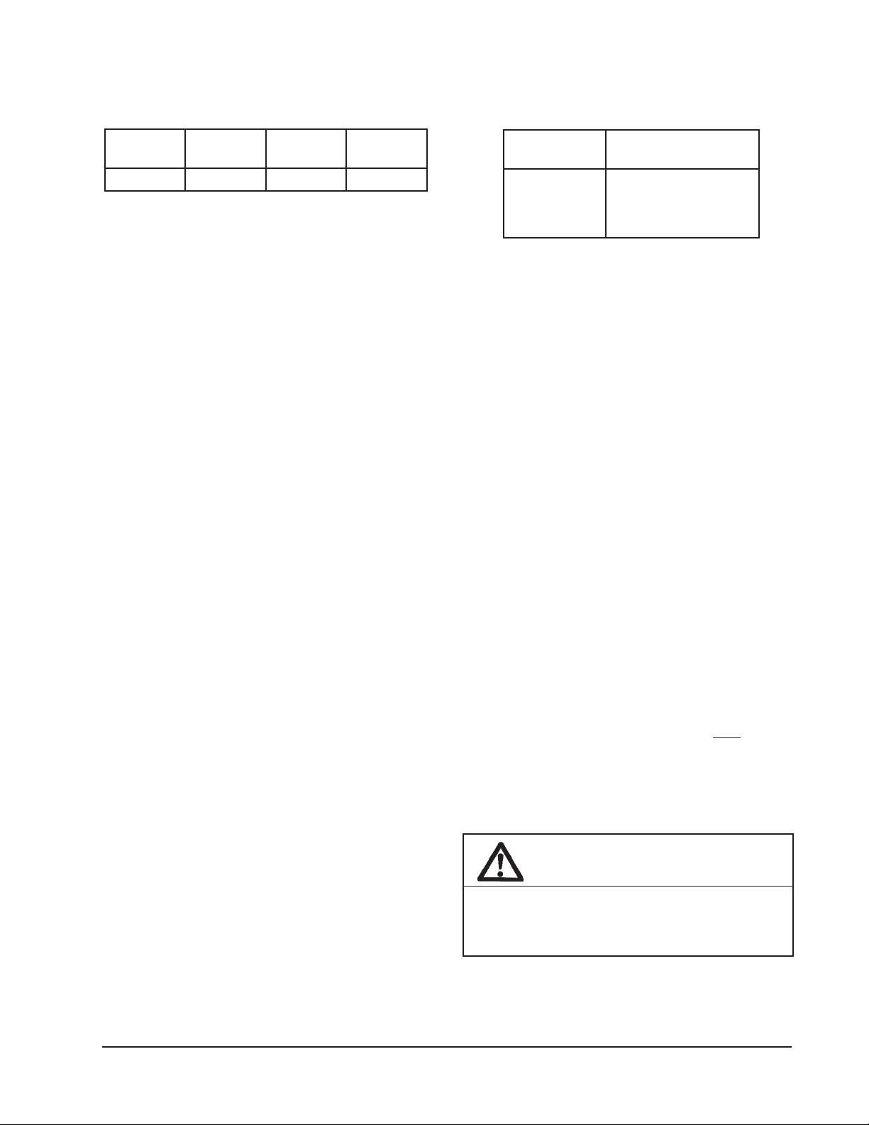
ELECTRICAL SPECIFICATIONS
ledoMegatloVspmA
4700-029802/0322.2V42
egatloV
GENERAL DESCRIPTION
The Energy Recovery Ventilator was designed to
provide energy efficient, cost effective ventilation to
meet I. A. Q. (Indoor Air Quality) requirements while
still maintaining good indoor comfort and humidity
control for a variety of applications such as schools,
classrooms, lounges, conference rooms, beauty salons
and others. It provides a constant supply of fresh air for
control of airborne pollutants including CO2, smoke,
radon, formaldehyde, excess moisture, virus and
bacteria.
The ventilator incorporates patented rotary heat
exchange state-of-the-art technology to remove both
heat & moisture and provides required ventilation to
meet the requirements of ASHRAE 62.1 standard.
It is designed as a single package which is factory
installed. The package consists of a unique rotary
Energy Recovery Cassette that can be easily removed
for cleaning or maintenance. It has two 15-inch
diameter heat transfer wheels for efficient heat transfer.
The heat transfer wheels use a permanently bonded dry
desiccant coating for total heat recovery.
Ventilation is accomplished with 2 blower/motor
assemblies each consisting of a drive motor and dual
blowers for maximum ventilation at low sound levels.
Motor speeds can be adjusted so that air is exhausted at
the same rate that fresh air is brought into the structure
thus not pressuring the building. The rotating energy
wheels provide the heat transfer effectively during both
summer and winter conditions.
lortnoC
ledoM
4700-029
ehthtiwesUroF
stinUgniwolloF
C-,B-,A-S2WQ
C-,B-,A-S3WQ
C-,B-,A-S4WQ
C-,B-,A-S5WQ
CONTROL REQUIREMENTS
1. Indoor blower motor must be run whenever the ERV
is run.
2. Select the correct motor speed on the ERV. Using
Table 1 of the ERV Installation Instructions
determine the motor speed needed to get the desired
amount of ventilation air needed. For instance, do
not use the high speed tap on a ERV if only 200
CFM of ventilation air is needed. Use the low speed
tap. Using the high speed tap would serve no useful
purpose and would effect the overall efficiency of the
air conditioning system. System operation costs
would also increase.
3. Run the ERV only during periods when the
conditioned space is occupied. Running the ERV
during unoccupied periods wastes energy, decreases
the expected life of the ERV, and can result in a large
moisture buildup in the structure. The ERV can
remove up to 60 to 70% of the moisture in the
incoming air, not 100% of it. Running the ERV
when the structure is unoccupied allows moisture to
build up in the structure because there is little or no
cooling load. Thus, the air conditioner is not running
enough to remove the excess moisture being brought
in. Use a control system that in some way can
control the system based on occupancy.
NOTE: The Energy Recovery Ventilator is NOT a
dehumidifier.
NOTE: Operation is not recommended below 5°F
outdoor temperature because freezing of
moisture in the heat transfer wheel can occur.
IMPORTANT
Operating the ERV during unoccupied periods
can result in a build up of moisture in the
classroom.
Manual 2100-533A
Page 3 of 12
Page 4
RECOMMENDED CONTROL
SEQUENCES
Several possible control scenarios are listed below:
1. Use a programmable electronic thermostat with
auxiliary terminal to control the ERV based on daily
programmed occupancy periods. Bard markets and
recommends Bard Part No. 8403-060 programmable
electronic thermostat for heat pump applications.
2. Use a motion sensor in conjunction with a
mechanical thermostat to determine occupancy in
the classroom. Bard markets the CS2000A for this
use.
3. Use a DDC control system to control the ERV based
on a room occupancy schedule.
4. Tie the operation of the ERV into the light switch.
The lights in a room are usually on only when
occupied.
5. Use a manual timer that the occupants turn to
energize the ERV for a specific number of hours.
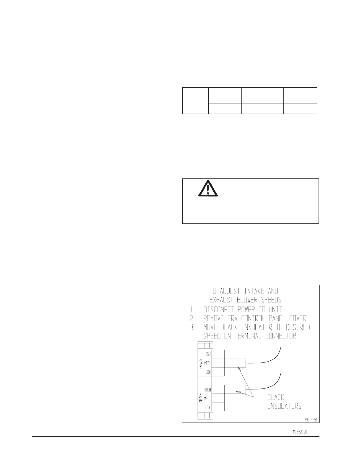
VENTILATION AIRFLOW
The ERV is equipped with a 3-speed motor to provide
the capability of adjusting the ventilation rates to the
requirements of the specific application by simply
changing motor speeds.
TABLE 1
VENTILATION AIR (CFM)
deepShgiH
)kcalB(
MFC
The ERV units are wired from the factory on medium
intake and low exhaust speeds. The ERV is equipped
with independently controlled 3-speed motor to provide
the capability of adjusting the ventilation rates to the
requirements of the specific application and to be able to
provide positive pressure in the structure. This is
accomplished by setting the intake blower on a higher
speed than the exhaust blower.
054573003
deepSmuideM
)eulB(
)deR(
deepSwoL
6. Use a programmable mechanical timer to energize
the ERV and indoor blower during occupied periods
of the day.
7. Use Bard Part No. 8403-056 CO2 controller for “ondemand” ventilation.
CONTROL WIRING
The QWSERV comes wired in the low voltage control
circuit from the factory.
With the “X” Remote Thermostat Option, it is default
wired into the “A” terminal, which drives the vent to
operate only during occupied periods when using a Bard
8403-060 thermostat or Bard CS2000 controller. If you
prefer for the QWSERV to operate anytime the blower
is operational, you will need to install a jumper wire
from “G” to “A”. If you prefer to use Bard 8403-056
CO2 controller to make the ventilation “on-demand”,
there is a connection adjacent to the thermostat
connections in the unit upper right-hand corner, and is
marked to match CO2 controller connections.
Furthermore, disconnect and tape off the wire as shown
in Figure 4 and you will need to field set the CO2 sensor
jumpers per Figure 5.
WARNING
Open disconnect to shut all power OFF before
doing this. Failure to do so could result in injury
or death due to electrical shock.
Moving the speed taps located in the control panel can
change the blower speed of the intake and exhaust. See
Figure 1.
FIGURE 1
BLOWER SPEED ADJUSTMENT
With the “D” Door Mounted Thermostat Option, the
thermostat is already connected and programmed to
operate the QWSERV only during occupied periods.
With the “H” Door Mounted Thermostat and CO
controller, the unit is ready to go with “on-demand”
ventilation as controlled by the CO2 controller.
Manual 2100-533A
Page 4 of 12
2
Page 5

PERFORMANCE AND APPLICATION DATA
1
1
TABLE 2
SUMMER COOLING PERFORMANCE
(INDOOR DESIGN CONDITIONS 75° DB / 62° WB)
tneibmA
.D.O
BW/BD
FseergeDTLVSLVLLVTRHSRHLRHTLVSLVLLVTRHSRHLRHTLVSLVLLVTRHSRHLRH
57
56412
08541
4886
501
07
08541
08541
0
56
08541
08541
0
08
09513
05121
04491
57
56412
05121
4139
001
07
25321
05121
202
56
05121
05121
0
06
05121
05121
0
08
09513
0279
07812
57
56412
0279
44711
59
07
25321
0279
2362
56
0279
0279
0
06
0279
0279
0
08
09513
0927
00342
57
56412
0927
57141
09
07
25321
0927
2605
56
0927
0927
0
06
0927
0927
0
08
09513
0684
03762
57
56412
0684
50661
58
07
25321
0684
2947
56
0684
0684
0
06
0684
0684
0
57
56412
0342
53091
07
25321
0342
08
570756
56
2524
06
0342
25321
2524
06
0
2299
0342
2281
0342
0
0
25321
0
2524
0
0
MFC054–ETARNOITALITNEV
ycneiciffE%56
25931
7749
5744
78871
05121
7375
7749
7749
0
05121
05121
0
7749
7749
0
05121
05121
0
33502
7987
53621
52362
52101
00261
25931
7987
4506
78871
52101
2677
9208
7987
131
39201
52101
861
7987
7987
0
52101
52101
0
7987
7987
0
52101
52101
0
33502
8136
51241
52362
0018
52281
25931
8136
4367
78871
0018
7879
9208
8136
1171
39201
0018
3912
8136
8136
0
0018
0018
0
8136
8136
0
0018
0018
0
33502
8374
49751
52362
5706
05202
25931
8374
3129
78871
5706
21811
9208
8374
0923
39201
5706
8124
8374
8374
0
5706
5706
0
8374
8374
0
5706
5706
0
33502
9513
47371
52362
0504
57222
25931
9513
39701
78871
0504
73831
9208
9513
0784
39201
0504
3426
9513
9513
0
0504
0504
0
9513
9513
0
0504
0504
0
25931
9751
27321
78871
5202
26851
9208
9751
9446
39201
5202
8628
4672
9751
4811
3453
5202
8151
9751
9751
0
5202
5202
0
9208
0
9208
39201
0
39201
4672
0
4672
3453
0
3453
0
0
0
0
0
0
MFC573–ETARNOITALITNEV
ycneiciffE%66
50811
8108
6873
01341
0279
0954
8108
8108
0
0279
0279
0
8108
8108
0
0279
0279
0
47371
2866
29601
06012
0018
06921
50811
2866
3215
01341
0018
0126
3976
2866
111
5328
0018
531
2866
2866
0
0018
0018
0
2866
2866
0
0018
0018
0
47371
5435
82021
06012
0846
08541
50811
5435
9546
01341
0846
0387
3976
5435
7441
5328
0846
5571
5435
5435
0
0846
0846
0
5435
5435
0
0846
0846
0
47371
9004
56331
06012
0684
00261
50811
9004
6977
01341
0684
0549
3976
9004
4872
5328
0684
5733
9004
9004
0
0684
0684
0
9004
9004
0
0684
0684
0
47371
2762
10741
06012
0423
02871
50811
2762
2319
01341
0423
07011
3976
2762
0214
5328
0423
5994
2762
2762
0
0423
0423
0
2762
2762
0
0423
0423
0
50811
6331
96401
01341
0261
09621
3976
6331
7545
5328
0261
5166
8332
6331
2001
5382
0261
5121
6331
6331
0
0261
0261
0
3976
0
3976
5328
0
5328
8332
0
8332
5382
0
5382
0
0
0
0
0
0
MFC003–ETARNOITALITNEV
ycneiciffE%76
7859
2156
5703
2156
2156
0
2156
2156
0
01141
7245
3868
7859
7245
0614
7155
7245
09
7245
7245
0
7245
7245
0
01141
1434
8679
7859
1434
6425
7155
1434
5711
1434
1434
0
1434
1434
0
01141
6523
45801
7859
7155
6523
6523
01141
7589
7155
0712
0712
7859
7155
9981
5801
7155
9981
0
336
6523
622
6523
0
6523
0
6523
0712
93911
0712
6147
0712
6433
0712
0
0712
0
5801
2058
5801
2344
5801
418
5801
0
0
7155
0
9981
0
0
LEGEND
VLT = Ventilation Load – Total HRT = Heat Recovery – Total
VLS = Ventilation Load – Sensible HRS = Heat Recovery – Sensible
VLL = Ventilation Load – Latent HRL = Heat Recovery – Latent
Manual 2100-533A
Page 5 of 12
Page 6

TABLE 3
WINTER HEATING PERFORMANCE — (INDOOR DESIGN CONDITIONS 70°F DB)
tneibmA
.D.OETARNOITALITNEV
BD
FseergeD
TLVSRHSLVTLVSRHSLVTLVSRHSLV
56034244916845202046158302618231292
06068488832790504082307704236562385
5509272385854157060294451106845893578
05027967774491001816569351084631356611
5405121027903425210110284291001824668541
04085414661161920512114899032027907970571
5301071806312043571411841139620431189291402
03044912555188830026122131870306921726013332
52078126947147345228126741364308541559114262
02003420449106840520220461848300261482316192
51037624831264355722224081232402871216418023
01061928233223850034238691716404491149519943
5095132725281365236232312200506012962711973
0020436127240860538246922783508622895812804
5-054630619209275730340642177500342629914734
01-088834011367770042344262651602952452126664
LEGEND
VLT = Ventilation Load – Total HRS = Heat Recovery – Sensible VLS = Ventilation Load – Sensible
.ffE%08MFC054.ffE%18MFC573.ffE%28MFC003
NOTE: Sensible
performance only
is shown for
winter application.
ENERGY RECOVERY VENTILATOR
MAINTENANCE
GENERAL INFORMATION
The ability to clean exposed surfaces within air moving
systems is an important design consideration for the
maintenance of system performance and air quality.
The need for periodic cleaning will be a function of
operating schedule, climate, and contaminants in the
indoor air being exhausted and in the outdoor air being
supplied to the building. All components exposed to the
airstream, including energy recovery wheels, may
require cleaning in most applications.
Rotary counterflow heat exchangers (heat wheels) with
laminar airflow are “self-cleaning” with respect to dry
particles. Smaller particles pass through; larger
particles land on the surface and are blow clear as the
flow direction is reversed. For this reason the primary
need for cleaning is to remove films of oil based
aerosols that have condensed on energy transfer
surfaces. Buildup of material over time may eventually
reduce airflow. Most importantly, in the case of
desiccant coated (enthalpy) wheels, such films can close
off micron sized pores at the surface of the desiccant
material, reducing the efficiency with which the
desiccant can adsorb and desorb moisture.
FREQUENCY
In a reasonably clean indoor environment such as a
school, office building, or home, experience shows that
reductions of airflow or loss of sensible (temperature)
effectiveness may not occur for ten or more years.
However, experience also shows that measurable
changes in latent energy (water vapor) transfer can occur
in shorter periods of time in commercial, institutional
and residential applications experiencing moderate
occupant smoking or with cooking facilities. In
applications experiencing unusually high levels of
occupant smoking, such as smoking lounges, nightclubs,
bars and restaurants, washing of energy transfer
surfaces, as frequently as every six months, may be
necessary to maintain latent transfer efficiency. Similar
washing cycles may also be appropriate for industrial
applications involving the ventilation of high levels of
smoke or oil based aerosols such as those found in
welding or machining operations, for example. In these
applications, latent efficiency losses of as much as 40%
or more may develop over a period of one to three years.
Manual 2100-533A
Page 6 of 12
Page 7

CLEANABILITY AND PERFORMANCE
In order to maintain energy recovery ventilation
systems, energy transfer surfaces must be accessible for
washing to remove oils, grease, tars and dirt that can
impede performance or generate odors. Washing of the
desiccant surfaces is required to remove contaminate
buildups that can reduce adsorption of water molecules.
The continued ability of an enthalpy wheel to transfer
latent energy depends upon the permanence of the bond
between the desiccant and the energy transfer surfaces.
Bard wheels feature silica gel desiccant permanently
bonded to the heat exchange surface without adhesives;
the desiccant will not be lost in the washing process.
Proper cleaning of the Bard energy recovery wheel will
restore latent effectiveness to near original performance.
MAINTENANCE PROCEDURES
NOTE: Local conditions can vary and affect the
required time between routine maintenance
procedures, therefore all sites (or specific units
at a site) may not have the same schedule to
maintain acceptable performance. The
following timetables are recommended and can
be altered based on local experience.
QUARTERLY MAINTENANCE
1. Inspect mist eliminator/prefilter and clean if
necessary. This filter is located in the wall sleeve
and can be accessed by either removing the exterior
louver grille, the vent package from inside the unit,
or by disconnecting the unit from the wall brackets,
and rolling the unit away from the sleeve on its
integral wheel system. The filter is an aluminum
mesh filter and can be cleaned with water and any
detergent not harmful to aluminum.
2. Inspect the comfort air filter and clean or replace as
necessary. This filter is located behind the fronthinged service door.
6. Use a shop vacuum with brush attachment to clean
both sides of the energy recovery wheels.
7. Reverse shop vacuum to use as a blower and blow
out any residual dry debris from the wheel.
NOTE: Discoloration and staining of the wheel
does not affect its performance. Only
excessive buildup of foreign material needs
to be removed.
8. If any belt chirping or squealing noise is present,
apply a small amount of LPS-1 or equivalent dry
film lubricant to the belt.
ANNUAL MAINTENANCE
1. Inspect and conduct the same procedures as outlined
under Quarterly Maintenance.
2. To maintain peak latent (moisture) removal
capacity, it is recommended that the energy
recovery wheels be sprayed with a diluted nonacid
based evaporator coil cleaner or alkaline detergent
solution such as 409.
NOTE: Do not use acid based cleaners, aromatic
solvents, temperatures in excess of 170°F or
steam. Damage to the wheel may result.
Do not disassemble and immerse the entire heat
wheel in a soaking solution, as bearing and
other damage may result.
3. Rinse wheel thoroughly after application of the
cleaning solution, and allow to drain before
reinstalling.
4. No re-lubrication is required to heat wheel bearings
of the drive motor, or to the intake and exhaust
blower motors.
5. If any belt chirping or squealing noise is present,
apply a small amount of LPS-1 or equivalent dry
film lubricant to the belt.
3. Inspect energy recovery ventilator for proper wheel
rotation and dirt buildup. This can be done in
conjunction with Item 2 above. Energize the energy
recovery ventilator after inspecting the filter and
observe for proper rotation and/or dirt buildup.
4. Recommended energy recovery wheel cleaning
procedures follow: Disconnect all power to the unit.
Open the front-hinged service door to the unit.
5. Remove the front cassette retaining panel from the
front of the ERV. Unplug the amp connectors to the
cassette drive motor. Slide energy recovery cassette
out of the ventilator.
Manual 2100-533A
Page 7 of 12
Page 8

If belts "squeak" or "chirp"
lubricate lightly with LPS-1
or equivalent "dry film"
lubricant.
FIGURE 2
BELT REPLACEMENT INSTRUCTIONS
Route (1) replacement belt
in top groove of pulley.
Route (1) replacement belt
in bottom groove of pulley.
Belt Replacement
Instructions
Manual 2100-533A
Page 8 of 12
MIS-2166
Page 9

FIGURE 3
HUB ASSEMBLY WITH BALL BEARINGS
Manual 2100-533A
Page 9 of 12
Page 10

Relay
Control
4
1
2
2
Motor Plug
Motor Plug
Exhaust
Motor
Blower
Capacitor
Exhaust
4
1
3
Exhaust
Motor Plug
Intake
Intake
1
Capacitor
Intake
Motor Plug
Ground
To Unit High Voltage 240/208-60-1
Power Plug
Speed Plug
Exhaust
32
1
2
3
Power Plug
Green
Black
Block
Term.
Black
23 23
23
2
2
4114-100
Motor
Blower
4
3
480V
208V
Transformer
120 V
Com
Speed Plug
Intake
Capacitor
Cassette
Motor Plug
4
3
1
Damper
Motor
Control Relay
Motor
Cassette
2
Motor Plug
Cassette
CO2 Disconnect
Red
Red
Relay
24
Control
29
Brown/White
Brown/White
Black/White
2134567891011
for Wiring Energy Recovery to Unit
12
Note: See Control Wiring Section of Installation Inst.
Black/White
Brown/White
CO2 SENSOR IS USED
DISCONNECT WHEN
2
27
Control Plug
21 3456789101112
Red/White
Brwn/White
Black/White
Orange
Black
1
Black/White
Blk/Red
Red
Transformer
480
240
208
COM
120 V
Exhaust
Speed
Plug
Black
Black
Black
Intake
Speed Plug
Yellow
White
Capacitor
WIRE FOR 208V OPERATION
TERMINAL BLOCK AND CONNECT RED
DISCONNECT ORANGE WIRE FROM
1
26
26
28
28
25
25
Note: See Control Wiring Section of Installation Inst. for Wiring Energy Recovery to Unit
25
25
28
28
26
Brown
Yellow
Green
Orange
26
26
2
3
Cassette
4
Motor Plug
Black
Capacitor
3
Motor
Red (Low Speed)
White
2
28
Motor Plug
Intake
Blue (Med. Speed)
1
Black (High Speed)
Intake
4
Blower
Red (Low Speed)
Blue (Med. Speed)
Black (High Speed)
White
25
2
431
Motor Plug
Exhaust
DANGER
!
*DISCONNECT POWER BEFORE
*ELECTRICAL SHOCK HAZARD
SERVICING.
WARNING
!
USE COPPER CONDUCTORS
75° C.
ONLY SUITABLE FOR AT LEAST
Motor
Blower
Capacitor
Exhaust
1
Black/White
White
Green
Brown
Motor
Cassette
Brown/White
Component Capacitor
Bl ower M otor 4/3 70
Cassette Motor 3/250
Motor
Intake
Damper
Manual 2100-533A
Page 10 of 12
Page 11

FIGURE 4
DISCONNECT & TAPE OFF WIRE
MIS-2759
DISCONNECT AND TAPE OFF FOR
CO2 CONTROLLED VENTILATION
Manual 2100-533A
Page 11 of 12
Page 12

FIGURE 5
FIELD SET CO
SENSOR JUMPERS
2
QWSERV VENT PACKAGE
2 CONTROLLER SETTING FOR 1000 PPM
CO
OFF
"SW1" SET TO ON
ON
OFF
OUTSW2SW1
ON
0-100%
AN
VOLTAGE
CURRENT
20-100%
"AN" SET TO VOLTAGE"SW2" SET TO ON
"OUT" SET TO 20-100%
MIS-2756
Manual 2100-533A
Page 12 of 12
 Loading...