


IMPORTANT
Installers' Information Manual, Users' Information Manual, Wiring Diagram, Parts List and
Warranty are inside or attached and should be read before the Installation is started or before
service is attempted.
After factory final assembly, this furnace has been dielectrically tested. Operation tests have
been performed on the burners, fan control and blower motor.
- TO THE INSTALLER -
AFFIX THIS PACKET ADJACENT TO
THE FURNACE.
- TO THE OWNER -
RETAIN THIS PACKET AND ITS CONTENTS FOR
FURTHER REFERENCE.
in
TABLE OF CONTENTS:
INSTALLERS' MANUAL
INSTALLERS' INFORMATION MANUAL
GAMA VENTING TABLES ADDENDUM
SIDEWALL VENTING ADDENDUM
USER'S MANUAL
(PRINTED IN RED AND BLACK AND INSERTED IN THE CENTER OF THIS PACKET.)
F\ (0 hi
408320 A
f
f'
r’i r\
>, C ;
t f
/■ /
i
ï: 7/- -i-
RAGE
1-35
36-62
63-66
MANUAL PACKET 403293 A
INSTRUCTION ASSEMBLY 408310 B
COVER ASSEMBLY 406303 A
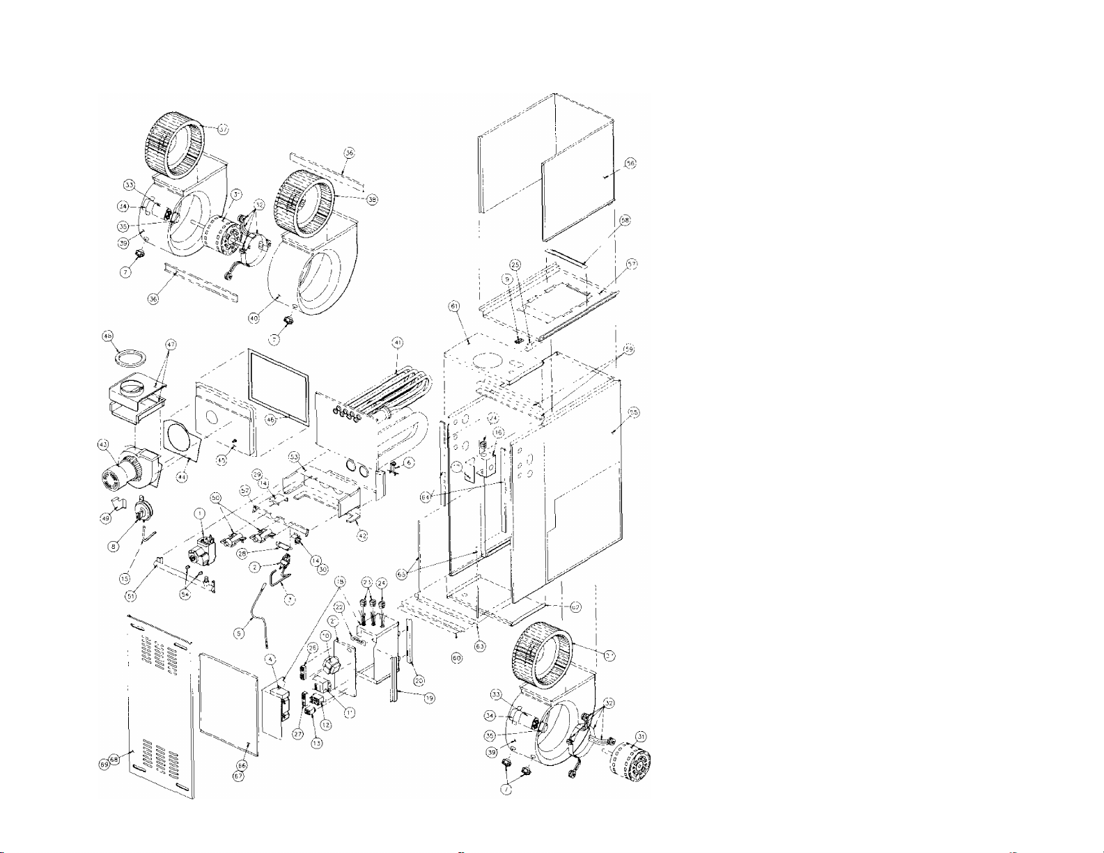
PARTS
FUNCTIONAL PARTS LIST
The format of this parts list allows you to get the part
number quickly. It allows you to easily identify the part and
the part number. Propane Conversion Kit and Filter Frames
are also listed in the parts list.
If you do not know the part number, find the part illustra
tion to the left and note the illustration number. Locate the
illustration number in the Parts List on the back foldout of
this packet Read across the list to locate the part number
for the appropriate size furnace.
EXAMPLE: You need an inducer motor relay for a
60,000 BTUH input 1/3 H.P. furnace:
1. Find the inducer motor relay in the
illustration and get the illustration
number (In this case 13).
2. Go to the table and read down to
illustration number 13.
3. Read across the row to find the part
number for the 60,000 BTUH input
1/3 H.P.furnace.
A.
Read part number 9043-316.
408360 A
INSTALLERS' MANUAL
To assure both sate and proper operation, please caretully toliow the instructions in this manual to
correctly install this new turnace.
ATTENTION, INSTALLER! After installing turnace, give the user:
—Users’ Information Manual —Parts List
—Installers’ Information Manual —Warranty Information
ATTENTION, USER! Your furnace installer should give you the above four important documents relating
to your furnace. Keep these as long as you keep your furnace. Pass these documents on to later furnace
purchasers or Users'. If any of the four documents is missing or damaged, contact your installer or furnace
manufacturer for replacement. For efficient service, please give your furnace model and serial number,
listed in Section 1 of your Users’ Information Manual or from your furnace rating plate. Throughout this
Installers' Information Manual, we frequently use the word "you" when referring to the person responsible
for application, installation and service of your furnace. Please remember to have only qualified service
technicians perform these services.
WARNING', Individuals who install this furnace, must have the training and experience necessary
to Install gas furnaces. They must also have training and experience necessary to Install related
comfort air conditioning appliances. Improper installation could create a hazard, resulting In damage,
injury or death.
While we have written these instructions as accurately and thoroughly as possible, they may not
cover every system variation or contingency. Also, questions of interpretation may arise. For more
information, solutions to particular problems or clarification, contact your focal distributor or the
manufacturer. See the furnace rating plate for who to contact.
Furnace installation must follow all applicable NATIONAL, STATE and LOCAL CODES.
UPFLOW
ELECTRONIC IGNITION INDUCED DRAFT FURNACE
WARNING: FOR YOUR SAFETY, WHAT TO DO IF YOU SMELL GAS:
— DO NOT TRY TO LIGHT ANY APPLIANCE;
— DO NOT TOUCH ANY ELECTRICAL SWITCH; DO NOT USE ANY PHONE IN THE BUILDING;
— IMMEDIATELY CALL YOUR GAS SUPPLIER FROM A NEIGHBOR'S PHONE; FOLLOW GAS
SUPPLIER'S INSTRUCTIONS;
— IF YOU CANNOT REACH GAS SUPPLIER, CALL FIRE DEPARTMENT.
HORIZONTAL
DOWNFLOW
IMPORTANT SAFETY NOTE: After installing the furnace, show the user how to turn off gas and
electricity to furnace. Point out control and switch locations for turning off gas and electricity. Go over
Sections 4 and 6 of Users' Information Manual and Section 29 in this manual with user. Make sure user
understands the importance of following all safety precautions.
920101
404200 A
SECTION
_________________________
TABiE Of CONTENTS
____________________________________
PAPE
SECTION 1
SECTION
SECTION 3
SECTION 4
SECTION 5
SECTION 6
SECTION
SECTION 8
SECTION 9
SECTION
10
SECTION 11
SECTION 12
SECTION
SECTION
13
14
SECTION 15
SECTION
SECTION
SECTION
16
17
18
SECTION 19
SECTION 20
SECTION 21
SECTION 22
SECTION
23
SECTION 24
SECTION 25
SECTION 26
SECTION 27
SECTION
28
SECTION 29
SECTION 30
PREPARING TO INSTALL FURNACE..............................................................................................................................2
IMPORTANT SAFETY RULES..........................................................................................................................................3
2
MEETING CODES.............................................................................................................................................................3
DETERMINING BEST FURNACE LOCATION..................................................................................................................3
IDENTIFYING FURNACE DIMENSIONS. SPECIFICATIONS, AND POSITION..............................................................4
ALLOWING FOR CLEARANCES.......................................................................................................................................7
SUSPENDING FURNACE.................................................................................................................................................8
7
PROVIDING FOR COMBUSTION AND VENTILATION AIR........................................................................................... 9
PROVIDING FOR PROPER VENTING
......
...........................................................................
-........................................13
TOOLS NEEDED FOR INSTALLATION..........................................................................................................................17
INSTALLING GAS PIPING.............................................................................................................................................. 18
INSTALLING ELECTRICAL WIRING.............................................................................................................................. 19
FOLLOWING FIELD WIRING DIAGRAMS......................................................................................................................19
ADJUSTING ROOM THERMOSTAT HEAT ANTICIPATOR...........................................................................................19
SEQUENCE OF OPERATION.........................................................................................................................................20
INSTALLING DUCTWORK..............................................................................................................................................20
SELECTING AND INSTALLING FILTER FRAMES.........................................................................................................23
CHECKING BEFORE STARTING FURNACE.................................................................................................................25
ADJUSTING PILOT..........................................................................................................................................................25
ADJUSTING MANIFOLD PRESSURE.............................................................................................................................26
CHECKING GAS INPUT..................................................................................................................................................27
ORIFICE SIZE..................................................................................................................................................................29
DERATING FOR HIGH ALTITUDES...............................................................................................................................29
ADJUSTING BLOWER SPEED.......................................................................................................................................30
MEASURING DUCT WORK STATIC PRESSURE.........................................................................................................31
MEASURING AIR TEMPERATURE RISE.......................................................................................................................32
CHECKING CONTROLS.................................................................................................................................................33
BLOWER TIMINGS..........................................................................................................................................................33
MAINTAINING FURNACE IN GOOD WORKING ORDER............................................................................................. 34
GETTING OTHER INFORMATION AND PUBLICATIONS.............................................................................................34
SICTION 1 -
PREPARING TO INSTALL TURNACB.
A. Literature.
Review this manual. Users’ Information Manual and Parts
List. In particular, see User's Information Manual and
Parts List for location and identification of furnace com
ponents.
After installing furnace, give this Installers' Information
Manual, Users' Information Manual, Warranty and Parts
List to user. You may have questions as you install the
furnace. If you need help on any of the installation in
structions or other matters relating to the furnace, contact
the office where you bought the furnace. You may also
refer to the furnace rating plate for a contact name.
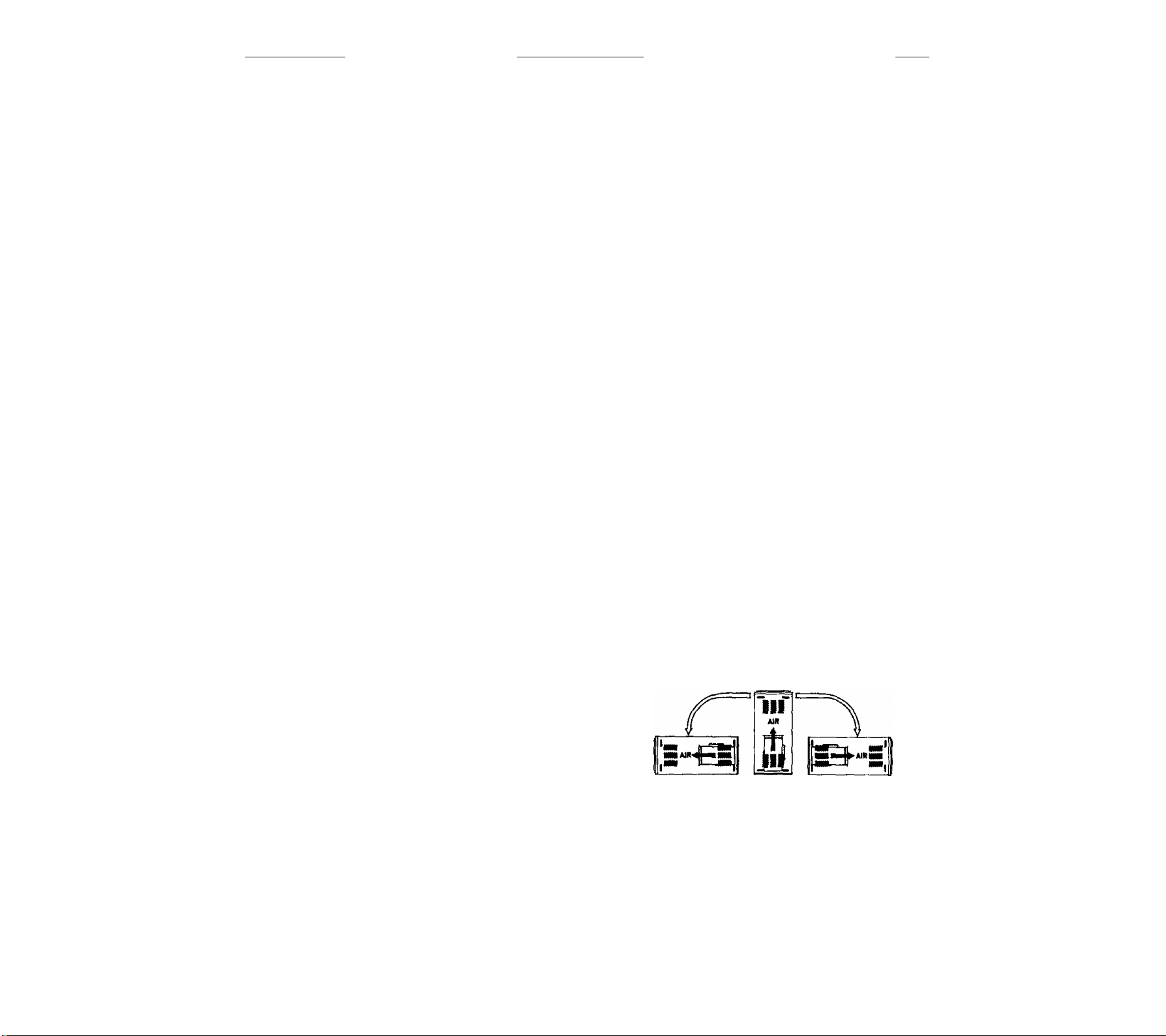
B, Installation Positions.
1. You may install furnace as-shipped in an upflow or
horizontal configuration in one of three positions
shown in Figure 1.
VENT
OUTLET
VENT
OUTLET
HORiZONTAL
LEFT SIDE DOWN
TVPE 1
UPftOW
TVPE 2
HORIZONTAL
RIGHT SIDE OOWN
TVPE 3
FIGURE 1
2. You may convert furnace quickly and easily from its
as-shipped configuration. After conversion, you can
install it as a downflow or horizontal furnace In one
of three positions shown in Figure 2.
VENT
OUTLET
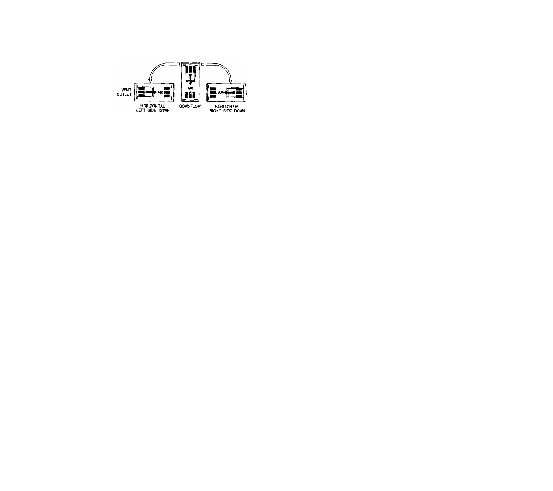
VENT
OUTLET
G. Provide adequate combustion and ventilation air to space
where furnace is being installed. See Section 8 for more
information. Connect this furnace to an approved vent
system, venting combustion products outdoors. See Sec
tion 9 for more information.
H. Never test for gas leaks with an open flame. Use a com
mercial soap made specifically for leak detection to check
all connections. See Section 11 for more information.
VENT
OUTLET
TYPE 4
TYPE 5
TYPE 6
FIGURE 2
SECTION 2 — IMPORTANT SAFETY RULES*
WARNING: Read and exactly follow these rules. Fail
ure to do so could cause Improper furnace operation,
resulting In damage, injury or death.
A. Signal words.
To alert you to potential hazards, we use the signal words
"WARNING" and "CAUTION" throughout this
manual. "WARNING" alerts you to situations that could
cause serious injury or death. "CAUTION” alerts you to
situations that could cause minor or moderate injury or
property damage. To help you, we use the words "must"
and "should" in this manual. "Must" is mandatory, "Should"
is advisory.
6. Use only the type of gas approved for this furnace; refer
to furnace rating plate.
WARNING: Only use natural gas In furnaces de
signed for natural gas. Only use Propane (LP) gas
for furnaces designed for Propane (L.P) gas. Make
sure furnace will operate properly on gas type avail
able to user. Do not use this furnace with butane.
Using wrong gas could create a hazard, resulting In
damage, injury, or death.
C. DO NOT install this furnace outdoors or in a mobile home,
trailer or recreational vehicle. It is not A.G.A. designcertified for these installations. This furnace is suitable
for a home built on site or manufactured home completed
at final site.
D. Carefully choose furnace installation site. DO NOT di
rectly expose furnace to drafts, wind or other outdoor
conditions. See Section 8 for more information.
E. DO NOT install furnace in a corrosive or contaminated
atmosphere. Make sure all combustion and ventilation
air requirements are adhered to in addition to local codes
and ordinances. See Section 8 for more information.
F. DO NOT use this furnace during construction when ad
hesives, sealers, and/or new carpets are being installed.
If the furnace must be used during construction, provide
clean outdoor air for combustion and ventilation to ^rnace
space. See Section 8 for more information.
I. Always install duct system with furnace. Be sure duct
system has external static pressure within allowable fur
nace range. See Sections 16 and 25 for more information.
J. Completely seal supply and return air ducts to furnace
casing. Duct work must run to an area outside furnace
air space. Seal duct work wherever it runs through walls,
ceilings or floors. See Section 16 for more information.
SECTION 3 — MEETING CODES.
Before installing furnace, make sure you know all applicable
codes, National, state and local codes may take precedence
over any instructions in this manual. Be sure to consult:
— Authorities having jurisdiction over furnaces;
— Local code authorities for information on electrical
wiring, gas piping and vent pipe;
— Current National Fuel Gas Code ANSI Z223.1/NFPA
54:
— Current National Electrical Code ANSI/NFPA 70.
See Section 30 for information on getting copies of these
codes.
SECTION 4 — DETERMINING BEST
FURNACE LOCATION.
You may install this furnace as an upflow or downflow fur
nace in an alcove, attic, basement, closet, garage, or utility
room. Install furnace so all electrical components are pro
tected from water.
You may install it as a horizontal furnace in an alcove, garage,
attic, basement or crawl space.
Select furnace location to meet all requirements in this manual,
making sure to refer to;
— Section 2 for safety rules;
— Section 6 for minimum clearances;
— Section 7 for furnace suspension;
— Section 8 for combustion and ventilation air;
— Section 9 for venting:
— Section 11 for gas piping;
— Section 12 for electrical wiring;
— Section 16 and 25 for duct work;
— Section 17 for filters.
Consult local code authorities for additional location require
ments.
Locate the furnace close to the chimney/vent and as near the
center of the air distribution system as possible. Install furnace
as level as possible.
Provide ample space for servicing and cleaning. Location
must allow 30 inches minimum front clearance for service.
Always comply with minimum clearances shown on inside of
front door. Do not install furnace directly on carpeting, tile or
any combustible material other than wood flooring.

NOTE: A combustible floor base, available from manu
facturer, is required for downflow furnace installation on
wood flooring.
HAZARDOUS LOCATIONS.
When furnace is in a residential garage, it must be installed
so that burners and ignition source are located no less than
fS'inches above the floor. Also, furnace should be protected
from physical damage by vehicles.
When furnace is in public garages, airplane hangers, or other
buildings having hazardous atmospheres, install unit in ac
cordance with recommended good practice requirements of
the National Fire Protection Association, Inc. See Section 30.
SECTION 5 — IDENTIFYING FURNACE DI
MENSIONS, SPECIFICATIONS, AND POSITION.
2, Furnace as-shipped position may be converted to a
downflow furnace by following instructions in B. be
low. Once conversion is complete, furnace may be
installed as a downflow furnace. Furnace may also
then be installed as a horizontal on its right or left
side. See Figure 2.
WARNING: Do not install furnace on its back. Doing so
could cause a fire, resulting In damage, injury or death.
See Figure 3 for dimensional drawings and specification table.
B. Converting furnace from as-shipped configuration.
READ ALL INSTRUCTIONS THOROUGHLY BEFORE
STARTING CONVERSION.
NOTE: Start conversion with furnace on its back.
A. A unique feature of this furnace is that it may be installed
as an upflow furnace, horizontal furnace, or downflow
furnace (minor conversion required).
1. Furnace as-shipped is an upflow furnace. Furnace
may be installed in this position or may be installed
as a horizontal on its right or left side without any
conversion. See Figure 1.
BTUH*
INPUT
40,000
40,000 1/3 3"
60,000 1/4 4"
60.000 1/3 4"
60,000
80,000
80,000
60,000
80,000 3/4 4"
100,000 1/3 4"
100,000
100,000 3/4 4"
120,000 1/2 5"
120,000
140,000 3/4 5"
140,000 3/4
'See Furnace rating plate located on blower door.
MOTOR*
H.P.
1/4
1/2 4“
1/4
1/3
1/2
1/2
3/4
VENT
DIAMETER
3"
4"
4"
4"
4"
5'
5'
FURNACE
WIDTH
A
14-1/2
14-1/2
14-1/2
14-1/2 12-7/8"
17-1/2
14-1/2
14-1/2
17-1/2
20-1/2 13-7/8" 18-15/16" (2) 10-4
17-1/2 15-7/8" 15-15/16"
17-1/2
20-1/2
20-1/2 18-7/8" 18-15/16"
20-1/2
23-1/2 21-7/8" 21-15/16"
23-1/2
RETURN
AIR SIZE
13- 23 /3 2" X B
WARNING: When servicing controls, all wires must
be labeled prior to disconnection. Mlswlring can cause
improper operation resulting In damage, Injury, or
death.
1. Remove front door. Study components described in
conversion. See Figure 4.
SUPPLY
AIR SIZE
78-1S/16'* X C
12-7/8" 12-15/16" 10-4 50-80
12-7/8* 12-15/16" 10-6
12-7/8" 12-15/16"
15-7/8" 15-15/16" 10-8
12-7/8" 12-15/16*
12-7/8" 12-15/16" 10-6
15-7/8" 15-15/16*
15-7/8" 15-15/16* 10-8
18-7/8"
18-7/8" 18-15/16" (2) 10-4
21-7/8"
12-15/16" 10-6 45-75
18-15/16"
21-15/16*
BLOWER
WHEEL
SIZE
10-4 45-75
10-4
10-8 50-80
10-6 55-85 1245
(2) 10-4
10-8
(2} 10-4
(2) 10-6
TEMP
RISE “F
30-60 1265
35-65 1635
50-80 915
40-70 1235
40-70 1930
50-80 1585
40-70
45-75 1660
45-75
45-75 I860
50-80 2235
CFM
at 0.50“ W.C.
805
850
1260
1645
1950
1965
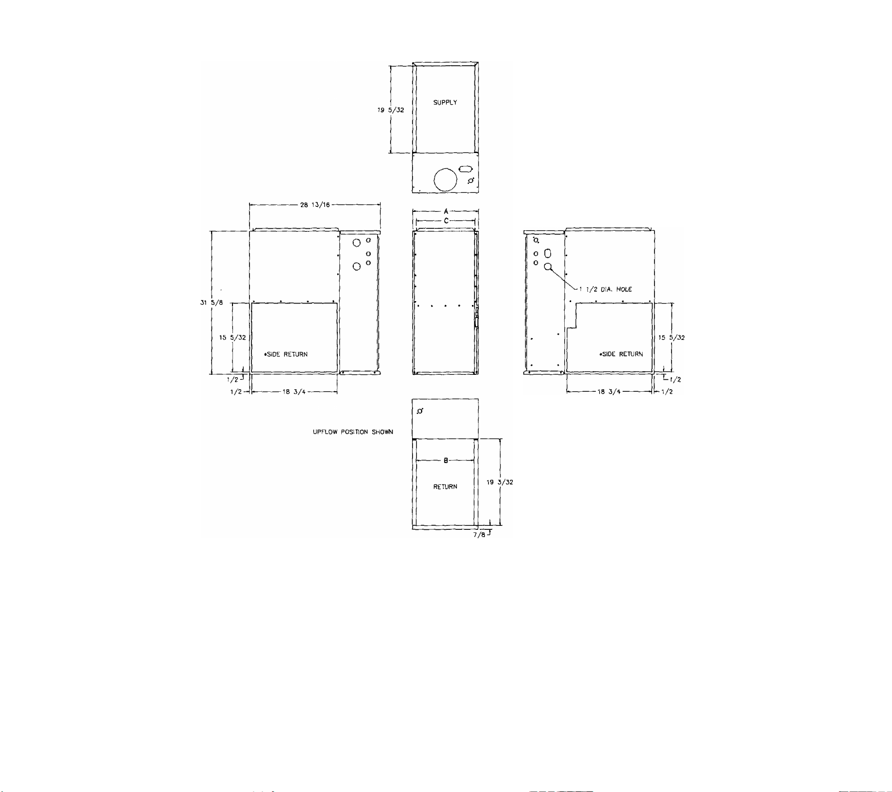
FURNACE AND DIMENSIONS SPECIRCATIONS
FIGURE 3
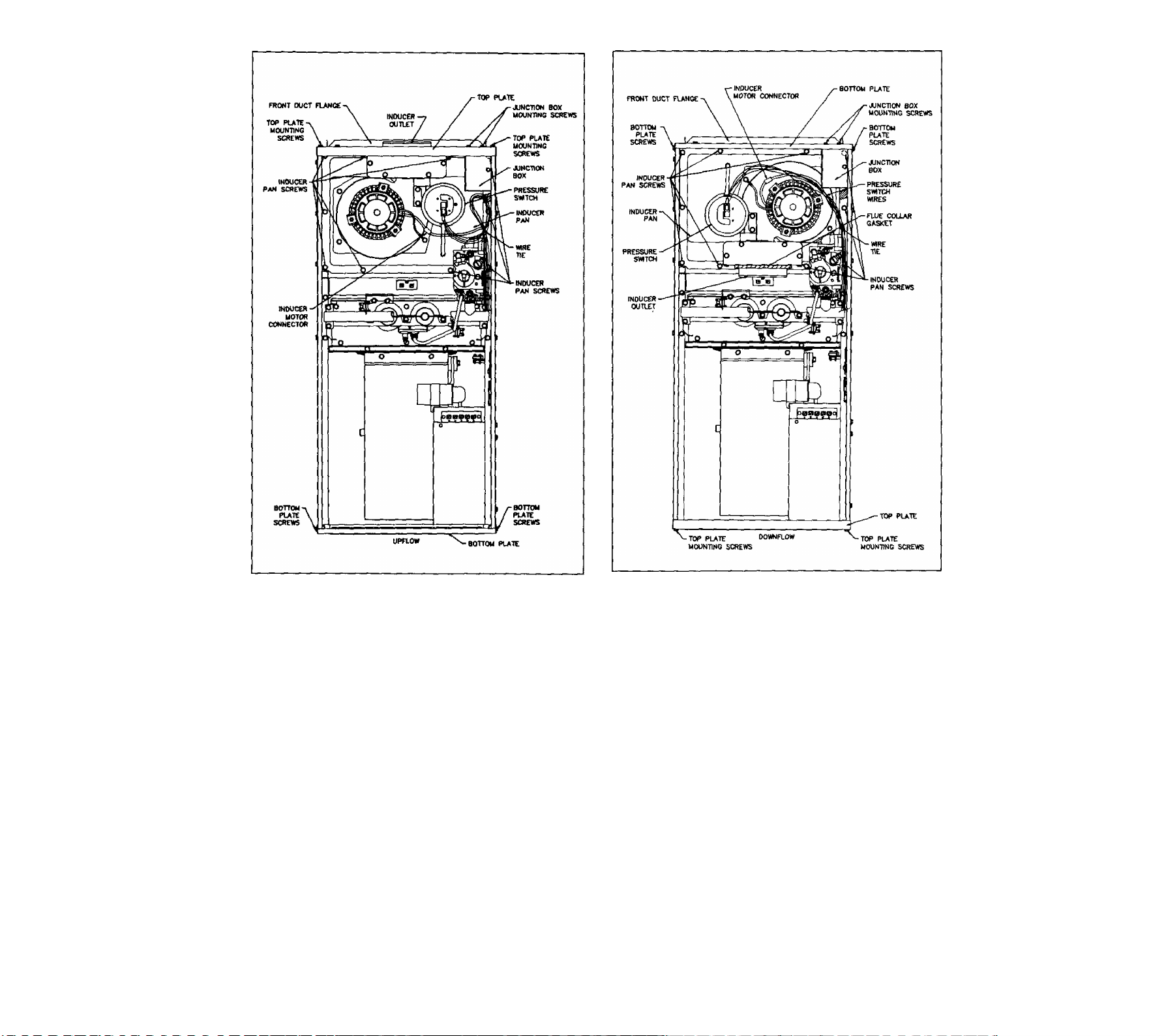
AS-SHIPPED CONFIGURATION
FIGURE 4
CONVERTED CONFIGURATION
FIGURE 5
2. Remove two junction box mounting screws from top
plate. Remove four top plate mounting screws. Save
all screws. Remove top plate and front duct flange.
3. Disconnect pressure switch wires and inducer motor
connector wires.
4. Remove ten screws from the inducer pan; save
screws. DO NOT drop screws into heat exchanger
openings.
5. Lift inducer pan (with inducer motor and pressure
switch stilt in place) about 1/4 inch and tilt left side
up to clear casing flanges. Use care not to damage
inducer gasket.
NOTE: If possible, decide on direction of gas entry
now. Screws to inlet gas valve fitting are accessible.
See Section 11.
6. Rotate inducer pan 180 degrees, line up mounting
holes and place inducer pan in furnace. Use care
not to damage gasket. Replace ten screws in in
ducer pan. See Figure 5.
7. Pressure switch wires will no longer reach pressure
switch. Remove cable tie around excess length of
red/yellow piggyback, blue and purple pressure switch
wires.
8. Connect pressure switch wires as follows. Wires are
numbered on insulation near terminals.
a. #1 Purple wire to pressure switch, terminal 'C
(Common).
b. #2 Blue wire to pressure switch, terminal 'NC
(Normally Closed).
c. #7 and #8 Red/Yellow piggyback wire to pres
sure switch, terminal 'NO' (Normally Open).
d. Route all pressure switch wires over inducer
motor.
e. Reconnect inducer motor connector.
f. Replace wire tie in area that prevents wires from
touching hot surfaces.

9. Rgmove four screws that secure bottom plate to cas
ing sides. Remove bottom plate; save screws,
10. Install top plate, removed in step 2, where bottom
plate was. Secure with four screws. Inducer outlet is
now lined up with vent outlet in top plate.
11. Stand up furnace with top plate down. Line front duct
flange up with holes. Place bottom plate on top of
duct flange and secure both to casing with four
screws.
12. Install junction box on bottom plate using two #6B
screws removed in Step 2. Junction box cover and
screw of junction box must face front of furnace.
13. Gasket around flue collar must be in place. If gasket
is loose, glue It. If gasket is damaged, replace it.
14. Install a single wall vent pipe section (minimum length
30 inches) (Field-Supplied) to inducer outlet with three
equally spaced screws. This pipe serves as an in
ducer outlet extension to which an appropriate vent
can be attached. Due to minor variations in vent pipe,
available from different manufacturers in the field,
and to assure the tightest seal possible, inducer out
let extension is not supplied with furnace. Additional
vent pipe sections or Type B1 adapter may then be
added when installing the furnace.
WARNINGS If Inducer outlet extension Is shorter than
30 Inches and chimney or vent becomes blocked, com
bustion products may be drawn Into furnace. This could
cause nausea or asphyxiation, resulting In Injury or death.
15. Conversion from as-shipped configuration is now
complete.
SECTION 6 — ALLOWING FOR CLEARANCES.
WARNING: Do not Install furnace on Its back, doing so
could cause a fire, resulting In damage. Injury or death.
Establishing clearances from combustible material.
Locate clearance label on inside of front door. See Figure 6.
WARNINGS Furnace Installation must meet all minimum
clearances from combustible material specified In this
manual and all applicable codes. Failure to provide re
quired clearance between furnace and combustible mate
rials could cause a fire, resulting In damage, injury, or
death.
WARNINGS This furnace Is A.G.A. design certified for
direct Installation on wood flooring for upflow and hori
zontal positions.
• Do not install furnace on carpeting, tile or other
combustible material.
• Do not Install furnace In a closet In horizontal
position.
• Do not Install furnace on wood flooring without
special base In downflow position.
MINIMUM INCHES CLEARANCE
CLOSET.
UPFLOW POSITION
• FOR CASING WIDTHS 17 INCHES OR LARGER 0 CLEARANCE MAY
BE USED. 18 INCH FRONT CLEARANCE REQUIRED FOR ALCOVE. FOR
INSTALLATION ON COMBUSTIBLE FLOORING.
MINIMUM INCHES CLEARANCE
CLOSET.
DOWNFLOW POSITJON
• FOR CASING WIDTHS 17 INCHES OR LARGER 0 CLEARANCE MAY
BE USED. 18 INCH FRONT CLEARANCE REOUIRED FOR ALCOVE. FOR
INSTALLATION ON COMBUSTIBLE FLOORING ONLY WHEN INSTALLED ON
SPECIAL BASE PART N0. 4-024400.
MINIMUM INCHES CLEARANCE
• CLEARANCE SHOWN IS FOR AIR INLET AND AIR OUTLET ENDS.
VENT MUST MAINTAIN CLEARANCE LISTED ABOVE.
FOR INSTALLATION ON COMBUSTIBLE FLOORING.
FOR HORIZONTAL POSITION LINE CONTACT IS ONLY PERMISSIBLE
BETWEEN LINES FORMED BY INTERSECTIONS OF TOP AND TWO SIDES OF
FURNACE JACKET AND BUILDING JOISTS. STUDS OR FRAMING.
ALL POSITIONS RLOUIRE 30 INCHES FRONT CLEARANCE FOR SERVICE*
TOP SIDES BACK
1 1* 0
1 0 0 2
TOP SIDES BACK
1 1* 0 6
1 0
HORiZONTAL POSmON
TOP SIDES* BACK
1 2*
1
2*
0 COMBUSTIBLE MATERIAL IN ALCOVE OR
FRONT VENT
0 COMBUSTIBLE MATERIAL IN ALCOVE OR
FRONT VENT
0 2
rO COMBUSTIBLE MATERIAL IN ALCOVE.
FRONT VENT
0 18
0 18
6 WHEN USING SINGLE WALL
6
1 WHEN USING B1
6 WHEN USING SINGLE WALL
1 WHEN USING B1
6 WHEN USING SINGLE WALL
1 WHEN USING B1
40ZB№
MINIMUM CLEARANCES
FROM COMBUSTIBLE MATERIALS
FIGURE 6
1. Upflow Installation.
Upflow position is approved for installation on
wood flooring. Typical upflow furnace installa
tions are an alcove, attic, basement, closet, ga
rage, or utility room. See Figure 6 or furnace
clearance plate for minimum clearances to com
bustible materials.
2. Horizontal Installation
a. Horizontal position is approved for installa
tion on wood flooring. Typical horizontal fur
nace installations are an alcove, garage, at
tic, or crawl space. See Figure 6 or furnace
clearance plate for minimum clearances to
combustible materials.
b. Attic Installation.
Line contact is permissible for furnaces
installed in horizontal positions. The in
tersection of furnace top and sides forms
a line. This line may be in contact with
combustible material. However, maintain
a 6" clearance to vent connection unless
Type B1 vent is used. See Figure 7.
Doing any of the above could cause a fire resulting in
damage, injury, or death.

TYPICAL ATTIC INSTALLATION
FIGURE 7
When using single wall vent pipe in horizon
tal installations, horizontal furnaces with
14.50" high casings must be raised 1" to
have 6” clearance to combustible material.
See Figure 7.
Furnace installation on combustible flooring is
permitted with combustible floor base available
from manufacturer. Read installation instructions
packaged with combustible floor base to correctly
install. See Figure 8.
c. Install a platform under furnace that extends
a minimum 30" in front of furnace. This pro
vides a work area and keeps insulating ma
terials away from combustion air openings.
Secure platform to ioists.
WARNINOs When a furnace Is installed
In an attic or other Insulated space, keep
all insulating materials at least 12" away
from furnace and all burner combustion
air openings. Failure to do so could cause
nausea, asphyxiation or fire, resulting In
damage. Injury, or death.
d. Crawl Space Installation.
Furnace can be hung from floor joists or in
stalled on suitable blocks or pad. Pad or
blocks should provide enough height to re
duce potential for water damage. See Sec
tion 7.
3. Downflow Installation.
You must convert furnace from as-shipped con
figuration for downflow furnace installation. See
Section 5.
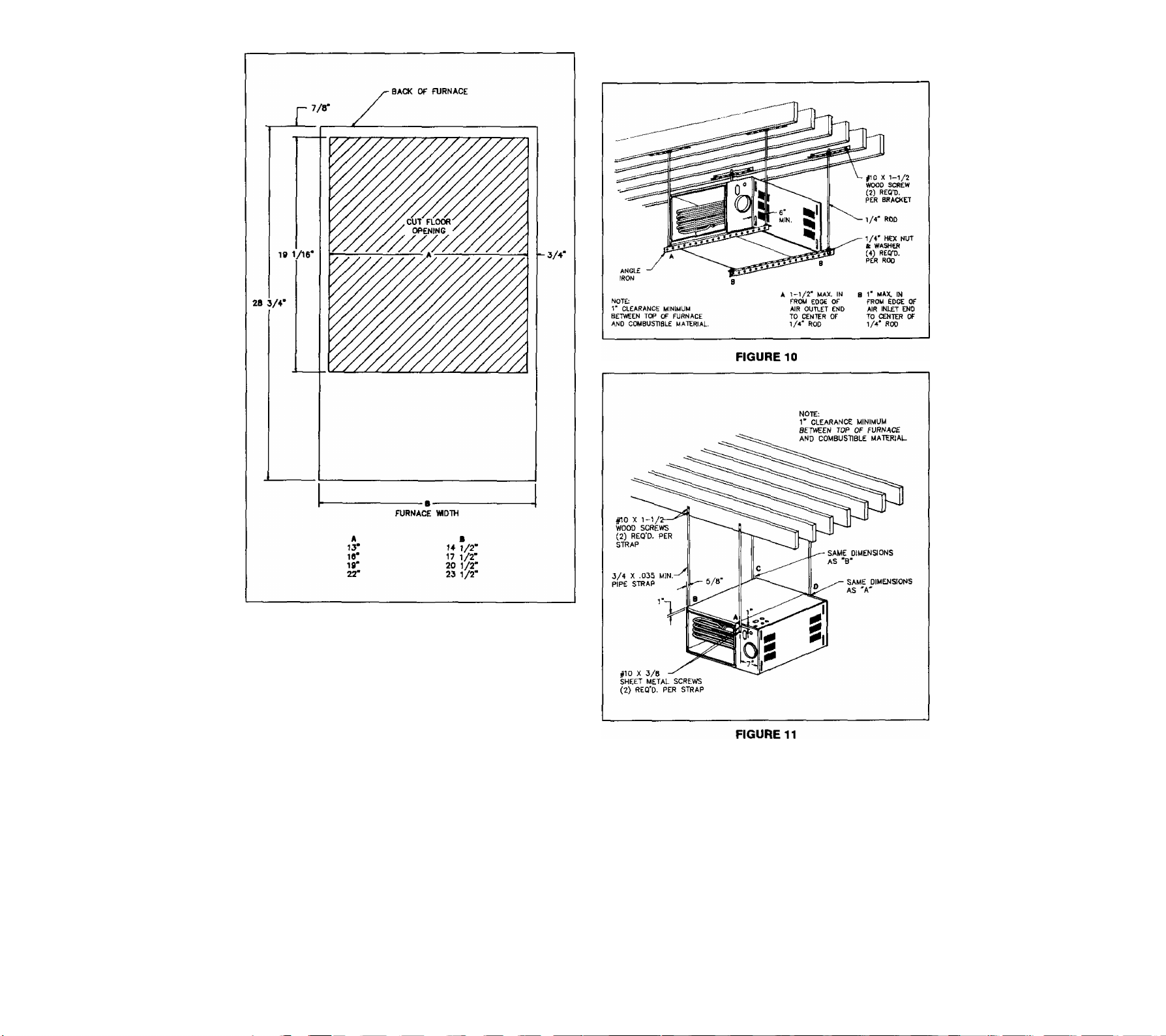
DOWNFLOW FLOOR OPENING
FIGURE 8
See Figure 9 for installation diagram on com
bustible floor.
4. Service Clearance.
Allow minimum front clearance of 30 inches for service.
See Figure 6 or inside of front door for minimum service
clearance.
SECTION 7 — SUSPENDING FURNACE.
Some installations will require that furnace be suspended
from rafters or floor joists.
A common way to do this using threaded rods is shown in
Figure 10. Consider this means when people may walk un
derneath furnace. Figure 11 shows another common suspen
sion means using pipe strap. Other means that provide ad
equate support may be used.
When furnace is not suspended in a crawl space, elevate
furnace off ground to avoid water damage and allow for air
conditioning coil drain.
Downflow position is approved for installation on
non-combustible flooring. Typical downflow fur
nace installations are an alcove, attic, closet,
basement, garage, or utility room. See Figure 6
or furnace clearance plate for minimum clear
ances to combustible materials.
NOTE: Level furnace from front to back and from left to right
within 1M" per four feet.
FURNACE, PLENUM, AND BASE INSTALLED ON A
COMBUSTIBLE FLOOR
FIGURE 9
SICTION S PROVIDING FOR COMBUSTION
AND ViNTILATION AIR.
Before you begin installing furnace, pian to provide enough
combustion and ventiiation air following:
— Current National Fuel Gas Code ANSI Z223.1/NFPA
54, Section 5;
— Local Code authorities. Refer to Section 31 of this
manual for these codes.
Ventilation is the process of replacing air which is required
for furnace operation. The total amount of ventilation air pro
vided within structure must equal all requirements of gas ap
pliances in the building, plus any air quantities removed by
range hoods, exhaust fans, etc.
Another reason to supply fresh outdoor air for combustion
and ventilation is that it dilutes contaminants found in indoor
air. These contaminants include bleaches, adhesives, clean
ing solutions, detergents, solvents, cat litter, spray can pro
pellants and most refrigerants.
WARNINDi Furnace and any other fuel-burning appli
ances must have enough fresh air for propsr combus
tion and ventilation. Lack of adequate combustion and
ventilation air could cause nausea or asphyxiation, re
sulting in injury or death.
WARNINOi During construction, do not use air from
inside structure for combustion and ventilation. Vapors
from soma construction adhesives and materials can be
come corrosive in the presence of a flame. This could
cause failure of heat exchanger or vent system, result
ing in damage. Injury or death.
WARNINO: Combustion and vsntllatlon air that contains
chlorine, fluorine, bromine and Iodine could cause heat
exchanger or vent system failure, resulting In damage,
Injury or death,
WARNINO: When installing a furnace In an attic or other
insulated space, keep furnace free and clear of all lnsu>
lating materials. Make surs all Insulation Is at least 12"
away from burner combustion air openings and well away
from openings into furnace space that supply air for
combustion and ventilation. Failure to do this could causa
nausea, asphyxiation or fire, resulting In damage, injury
or death.
WARNINGS When Installing furnace in an alcove, attic,
basement, closet, garage, or utility room do not store
items in front of furnace or In front of closet or utility
door which would block combustion air openings to fur*
nace. Failure to do this could cause nausea, asphyxia
tion or fire, resulting In damags, Injury or death.
DO NOT install furnace where any combustion or ventilation
air openings will allow outside air to blow directly against
furnace.
WARNINGS Drafts blowing directly against furnace could
cause improper combustion which could cause heat ex
changer failure or fire, resulting In damage, Injury or
death.
Sufficient air MUST be provided to insure there wilt not be a
negative pressure in furnace room or space. In addition, there
MUST be a positive seal between furnace and return air duct
to avoid pulling air from burner area.
Provide adequate combustion and ventilation air by consider'
ing volume of furnace installation space. Use these instruc
tions and current National Fuel Gas Code ANSI Z223.1/NFPA
54 to determine whether furnace is in an unoonfined or con
fined space.
If ratio is less than 50, installation space is a con
fined space. If ratio is 50 or greater, installation space
is an unconfined space.
B. Installing furnace In confined space.
WARNING: You must provide permanent air open
ings to a conflned furnace installation space from
another area as described below. Failure to do ao
could result In Inadéquat# combustion and vsntllatlon
air. Thsae could cause nausea, asphyxiation or fire,
resulting In damage, injury or death.
1. Combustion and ventilation air openings.
a. All combustion and ventilation air from inside the
structure.
1. The furnace space must be provided with
two permanent openings to an additional
room(s) of sufficient volume so that the
combined volume of all spaces meet the cri
teria above for an unconfined space.
The total input of all gas appliances within
the combined space must be considered in
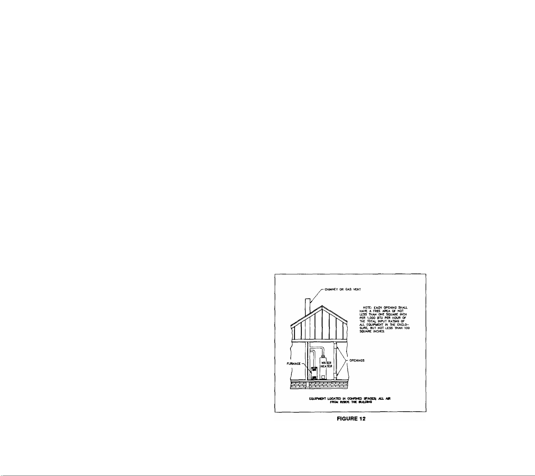
making this determination. See Figure 12.
2. a. Each opening must have minimum free
area of one square Inch per 1,000 Btuh
per hour of the total combined input rat
ing of all gas appliances within the con
fined furnace space, but not less than
100 square inches. One opening must
be within 12 inches of the top and an
other opening within 12 inches of the
bottom of the furnace space. See Fig
ure 12.
A. Determining If your space Is confined or unconflned.
Two factors determine whether a furnace installation
space is confined or unconfined:
— Volume of installation space;
— Total gas input of appliances to be installed in that
space.
To determine which your space is:
1. First calculate furnace installation space volume in
cubic feet.
2. Determine combined input rating (BTUH) of all gas
appliances in furnace installation space, including
furnace input. This is the total combined input rating.
3. Divide total combined input rating by 1,000. Then
divide this number into installation space volume.
Here's the formula:
Space Volume
Ratio
Total lnput/1,000
10
For example:
Total Input
Btuh (square Inches)
40,000-100,000 100
120,000 120
140,000
b. If building is of unusually tight construc
tion, provide a permanent opening di
rectly communicating with the outdoors.
Opening shall have a minimum free area
of one square inch per 4000 Btuh of
total input rating for all equipment in the
enclosure.
If return air is taken directly from hall
way or space next to furnace that com
municates with furnace spaces, all air
for combustion must come from out
doors.
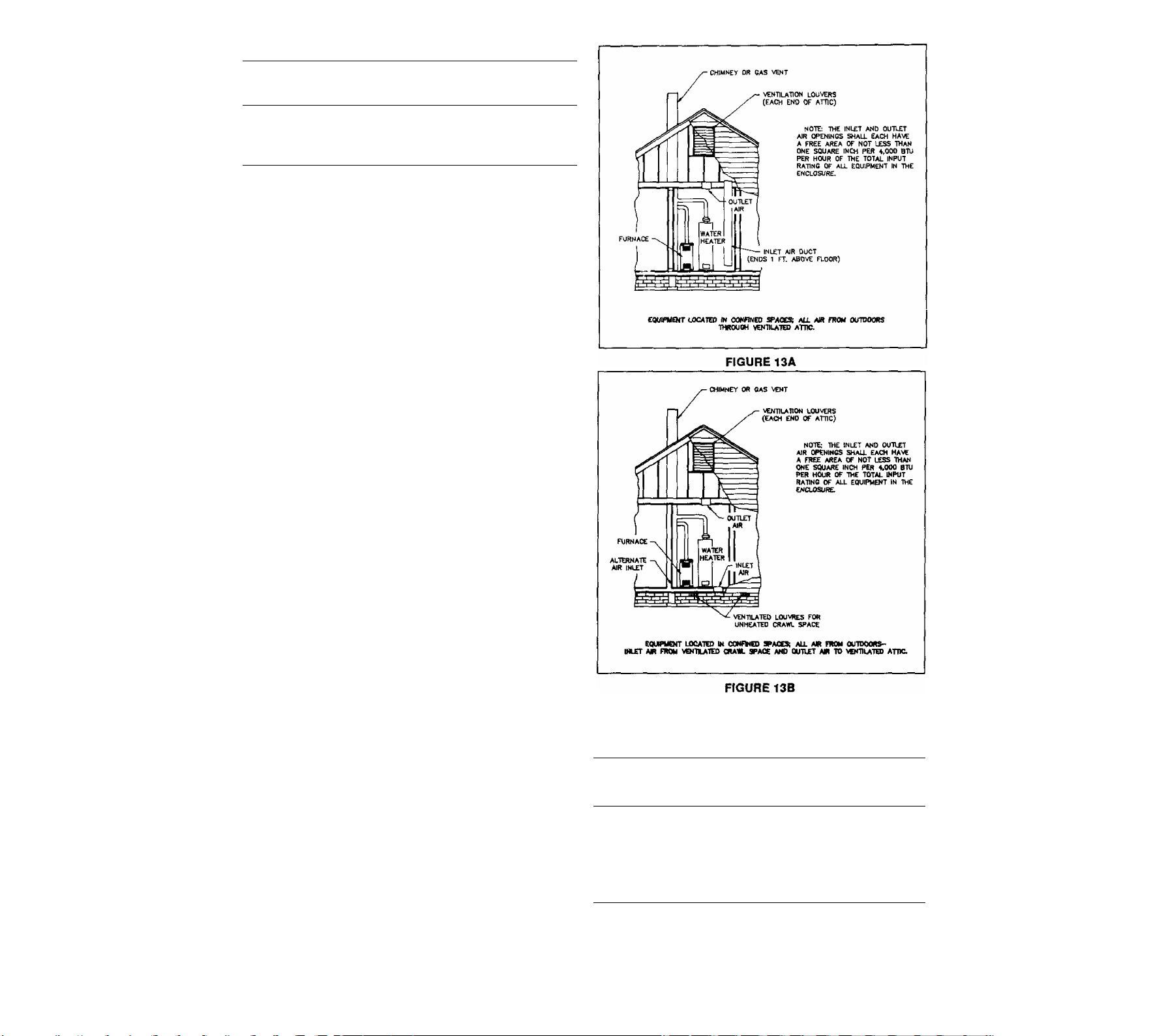
b. All combustion and ventilation air from outdoors.
1. The furnace space must be provided with
two permanent air openings directly to the
outdoors, or by ducts to the outdoors or
spaces (attic or crawl spaces) that freely ac
cess the outdoors. These combustion and
ventilation openings will give fresh air free
access to furnace space for combustion and
ventilation. You must also provide air suffi
cient for all other gas appliances within fur
nace space.
Free Area Per Opening
140
Ducts must freely access outdoors or spaces
(attic or crawl spaces) which freely access
the outdoors. Well ventilated attics or crawl
spaces usually satisfy this requirement.
2. Locate one combustion and ventilation air
operîing within 12" of top of furnace space.
Locate another within 12" of bottom of fur
nace space.
3. When directly accessing the outdoors, each
opening must have a minimum free area of
one square inch per 4,000 Btuh of total
combined input rating of all gas appliances
within furnace space. See Figure 13A.
4. If combustion air ducts will run vertically,
ducts and each opening must have a mini
mum free area of one square inch per 4,000
Btuh total combined input rating. You must
allow for all gas appliances within the fur
nace space. See Figure 13B.
For example:
Required
Total Input
Btuh
40,000 10.0 4
60,000 15.0 5
80,000
100,000
120,000 30.0 7
140,000 35.0
Free Area per Opening
(square inches)
20.0 6
25.0 6
Suggested
Round Pipe
(inches dia.)
7
11
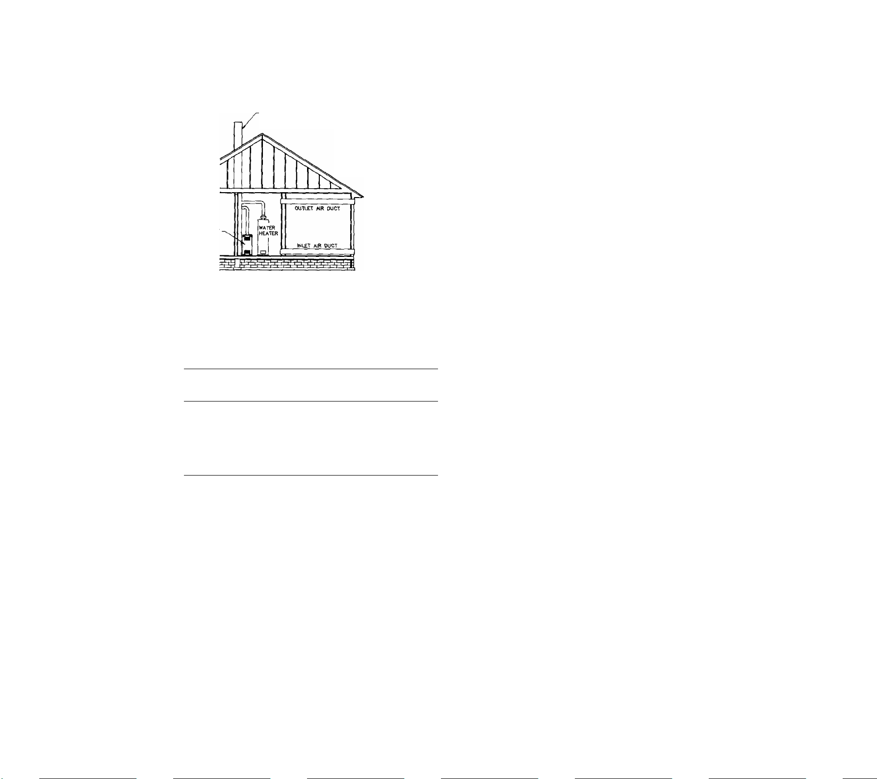
5. if combustion air ducts will run horizontally, ducts
and each opening must have a minimum free
area of one square inch per 2,000 Btuh total
combined input rating. You must allow for all
gas appliances within the furnace space. See
Figure 14.
CHIMNEY OR CAS vent
NOTE: EACH AIR DUCT
OPENINO SHALL HAVE A
FREE AREA OF NOT LESS
THAN ONE SQUARE INCH
PER 2.000 BTU PER HOUR
OF THE TOTAL INPUT RATInC
OF ALL EQUIPMENT IN THE
ENCLOSURE
to 25% free area. Assume metal louvers and grilles
have 60 to 75% free area. Refer to current National
Fuel Gas Code ANSI Z223.1/NFPA 54.
Example: Furnace is 100,000 Btuh input and is to be
installed in a confined space that contains no other
gas appliances. Rectangular combustion and ventilation air ducts will run horizontally from outdoors to
furnace space.
a. Calculate free area required.
Because combustion and ventilation air ducts run
horizontally, allow 2,000 Btuh. See 2b. above.
Furnace Input
Btuh
Free Area Required
2,Q0Q Btuh
per square inch
IF THE EQUIPMENT ROOM IS LOCATED AGAINST AND OUTSIDE WALL ANO THE AIR OPENINGS
COMMUNICATE OIRECTLY WITH THE OUTDOORS. EACH OPENING SHALL HAVE A FREE AfffiA
OF NOT less than one SQUARE INCH PER 4,000 BTU PER HOUR OF THE TOTAL INPUT
RATING OF ALL EQUIPMENT IN THE ENCLOSURE.
EQUIPMENT LOCATED IN CONFINED SPACES; ALL AIR FROM OUTDOORS.
FIGURE 14
For example:
Total input
Btuh
Free Area per Opening
(square Inches)
Round Pipe
(Inches dia.)
40,000 20 6
60,000 30
80,000 40
100,000
50 8
120,000 60 9
140,000 70
6. Ducts which introduce combustion and ventila
tion air from outside structure into furnace space,
must have the same cross sectional area as the
free area of openings to which they connect.
The minimum dimension of rectangular air ducts
shall not be less than 3 inches.
2. Louvers, grilles, and screens.
Sometimes, louvers, grilles, or screens cover com
bustion and ventilation air openings. If so, you must
provide larger openings than those calculated above.
This is necessary because louvers, grilles and
screens block and reduce an opening's free area.
Louver, grille and screen manufacturers supply tech
nical data on their products, which usually includes
the Tree area." Sizing the openings with louvers,
grille or screen in place will provide minimum free
area to furnace space as calculated above. Do not
use screen smaller than 1/4" mesh. If you do not
know free area, assume that wood louvers have 20
7
8
10
100,000
50 square inches
2,000
Each opening must have a free area of 50 square
inches.
Calculate overall area of openings to give needed
b.
free area once you cover them to keep out rain
and other outside elements.
Example: If you will use wood louvers to cover
combustion and ventilation air openings and you
do not know free area of wood louvers, use 20%,
as suggested in ANSI Z223.1/NFPA 54.
100 x Free area
from a) above)
Louver free area
openings expressed
overall area of
openings with wood
louvers installed
as a percentage
100 x 50
250 square inches
20
Each of the two combustion and ventilation air
openings must have a total area of 250 square
inches. This is when wood louvers cover openings
for a 100,000 Btuh input furnace and combustion
and ventilation air ducts run horizontally.
c. Calculate minimum rectangular duct size needed.
If you choose a rectangular duct with the mini
mum allowed dimension of 3", the other duct
dimension must be at least 16-2/3". This is cal
culated by dividing the 50 square inches of free
area from a) by 3", with equals 16-2/3".
WARNINGi You must fix combustion and ventila
tion air louvers and grilles In open position or Inter
lock them with furnace operation. Furnace operation
12

with louvvrs or grilles closed could cause Inadequate
combustion or ventilation air, resulting In Injury or
death.
C. Installing furnace in unconfIned space.
Refer to current National Fuel Gas Code ANSI 2223.1/
NFPA 54 for more information. This code does not re
quire that you make special provisions for combustion
and ventilation when furnace is in an unconfined space.
However, it is always prudent to arrange for combustion
and ventilation air as if installation space is confined
space.
In the past, infiltration through loose construction pro
vided enough air for combustion and ventilation when
furnace was in an unconfined space. Current construction
methods may now prevent infiltration of air into unconfined
space. These current methods include increased insula
tion, vapor barriers, tight fitting doors and windows, and
weather-stripping.
D. Allowing for exhauet fan operation.
1, When furnace is in a ventilated attic, crawl space,
residertce garage, or outside the heated space, ex
haust fan drafts can adversely affect its operation.
These drafts can come from kitchens, bathrooms,
clothes dryers or anywhere within the heated space.
WARNING: Exhaust fans that blow against fur
nace could cause heat exchanger failure or fire,
resulting In damage, Injury, or death.
2. When furnace is in a repair garage or inside the
heated space, exhaust fans can adversely affect its
operation. Exhaust fans in kitchens, bathrooms,
clothes dryers or anywhere within heated space in
crease combustion and ventilation air requirements.
This is because exhaust fans reduce the amount of
combustion and ventilation air available to the fur
nace. A fireplace also reduces amount of combus
tion and ventilation air. You must allow for these
reductions.
WARNING: You must allow for reduction of air
available for combustion and ventilation by ex
haust fans and fireplaces. Failure to do so could
result In Inadequate combustion and ventilation
sir. This could cause nausea, asphyxiation, or
firs, resulting In damage, Injury, or death.
3. Exhaust fan air may contain compounds of chlorine,
fluorine, bromine, and iodine. If used for combus
tion, this contaminated air will adversely affect fur
nace operation.
WARNING: If used for combustion and ventila
tion, contaminated exhaust fan air could cause
heat exchanger or vent system failure resulting
In damage, Injury, or death.
SICTION 9 —
PROVIDING P
Vent furnace using these instructions and Venting Adden
dum. Also, meet requirements of local utilities and other local
code authorities. You must connect furnace to a vent or fac
tory-built chimney or a suitably sized, constructed and lined
masonry chimney. Vent or factory-built chimney must meet a
recognized standard. Chimney lining method and material
must comply with local requirements. Use corrosion-resistant
material meeting nationally recognized standards for vent
construction.
INTING.
WARNING: Inadequate vent or chimney could allow
combustion products to collect In structure, resulting In
Injury or death.
WARNING: Vent this furnace separately from any appli
ance designed to burn solid fuel, particularly wood-burn-
Ing or coal burning appliances. Improper venting could
allow combustion products to collect In structure, result
ing In injury or death.
A. Venting category.
The furnaces covered by this manual are design-certified
as CATEGORY 1 for venting, CATEGORY 1 furnaces
have non-positive vent static pressure and rely on the
beat content of combustion products to vent. You may
common vent CATEGORY 1 furnaces.
The furnaces covered in this manual are also designcertified as CATEGORY 3 for venting, only when they
are installed with manufacturer specified vent system
components and installation practices.
Category 3 gas appliances rely on the heat content of
combustion products and mechanical or other means to
vent. You may not common vent CATEGORY 3 gas ap
pliances.
B. Types of vent systems.
These definitions will help you understand the terms we
use.
1. "Vent" and "chimney" refer to open passageways.
These passageways convey vent gases from vent
connectors to the outside. Gases begin their final
ascent at the vent or chimney. Vents and chimneys
usually run vertically or nearly vertical. When they
serve only one gas appliance, they are called "dedi
cated" vents or chimneys. Whan they serve multiple
gas appliances, they are called "common" vents or
chimneys.
2. A "vent connector" connects a gas appliance to a
vent or chimney. Vent connectors usually run directly
from the furnace draft inducer collar to vent or chim
ney. Vent connectors may have vertical and horizon
tal runs.
3. A "venting system" is a continuous open passage
way from the draft inducer collar to the outside.
Venting systems usually have vent connector(s) and
a vent or chimney. Venting systems commonly serve
a single furnace or a single furnace and a water
heater. Other multiple-appliance venting systems are
13
less common.

C. Design considerations.
1. General considerations.
Avoid oversizing furnace for your application. Se
lect a furnace model with a rated heating output
close to the calculated heating toad. This extends
the firing period, decreasing the potential for con
densate formation in the vent.
a. Too small a vent cannot carry all combustion
products outdoors. Too large a vent will not vent
combustion products rapidly enough to avoid
potential for condensation. Refer to Venting Ad
dendum for correct size vent.
b. Vent height must be a minimum of five feet.
Minimize vent connector horizontal runs to the
extent possible for best performance.
c. The designer must consider the building's ori
entation, answering these questions. Will the
vent terminate outside the building where its op
eration could be adversely affected by winds?
Could any adjacent buildings adversely affect
vent operation? Allowing for these factors can
reduce the possibility of downdraft conditions.
b. Use Type B1 vent connectors in or through at
tics, crawl spaces, or other cold areas. Install
thimbles that meet local codes when vent con
nectors pass through walls or partitions of com
bustible material.
c. Keep vent connectors as short as possible by
locating furnace as dose as practical to vent or
chimney. Avoid unnecessary turns or bends
which create resistance to
Adding an elbow adds resistance. For example,
adding a 6" 90-degree elbow would be the
equivalent of adding 20 feet of horizontal 6" pipe.
45-degree elbows have lower resistance than 90degree elbows, and can work for most vent runs.
d. You may increase vent connector diameter to
overcome installation limitations and obtain con
nector capacity equal to furnace input. Make this
increase as close as possible to draft inducer
collar, allowing for necessary adapters and fit
tings.
e. If you join two or more vent connectors before
they enter the vertical vent or chimney, use cau
tion. See Venting Addendum.
flow of vent gases.
d. If your local experience indicates possible con
densation problems, provide for draining and
disposal of venting system condensate.
2. Vent sizing.
a. Sometimes the horizontal distance from the fur
nace to the vent or chimney is already given;
this is known as the horizontal vent connector
run. The vent or chimney height is also usually
given as is the Btuh input of the gas appliances
served by the vent.
Check these parameters to be sure the venting
system will work. Use approved engineering
practices, Venting Addendum, these instructions,
and Part 7 of current National Fuel Gas Code
ANSI Z223.1/NFPA 54. Use vent capacity tables
in Venting Addendum to check existing or new
vent sizes for CATEGORY 1 furnaces.
b. See Venting Addendum for single appliance
venting and multiple appliance (common) vent
ing. For multi-story installations, refer to current
National Fuel Gas Code ANSI Z223.1/NFPA 54.
c. Minimum vent connector diameter from furnace
to vent or chimney is same as draft inducer col
lar.
3. Vent connector.
a. Vent connectors must be made of noncombus
tible, corrosion resistant material capable of
withstanding vent gas temperatures. They must
be thick enough to withstand physical damage
and be accessible for inspection, cleaning and
replacement.
f. Do not connect this furnace to any portion of a
vent system which operates under positive pres
sure. Positive pressure would result with CAT
EGORY 3 and 4 appliances connected to the
vent.
g. Do not connect vent connector to a chimney flue
serving a fireplace unless you permanently seal
fireplace flue opening.
4. Vertical vent or chimney.
a. Vents and chimneys usually extend vertically with
offsets not exceeding 45-degrees. Consider vent
pipe runs more than 45'degrees as horizontal
runs. Include their length in the total horizontal
run.
b. Designer and installer must provide an appropri
ately sized common vent for all appliances con
nected to it. See Venting Addendum.
c. Connect this CATEGORY 1 furnace only to vent
systems with other CATEGORY 1 appliances.
WARNING: Do not connect this Category 1
furnace to a vent system used by Category 3
and 4 appliances. Do not connect It to vents
with mechanical draft systems operating at
positive pressure. Improper venting could al
low combustion products to collect in struc
ture during use, resulting In damage, Injury
or death.
5. Chimney.
Furnace is suitable for venting into a properly sized
and lined masonry chimney. Consult National Fuel
Gas Code ANSI Z223.1/NFPA 54 for construction
details. If chimney is oversized, liner is inadequate
14
OT evidence of condensate exists, consider using
chimney as a pathway for suitably sized Type B1
vent liner. See Figure 15.
FIGURE 15
WARNIN9I Support Type B1 vent liner in ma
sonry chimney. Maintain at least a 1" clearance
on all sides to reduce possibility of condensate
in vent. Condensate may cause vent to deterio
rate allowing combustion products to collect In
structure, which could result In injury or death.
See Figure 16.
NOTE; For more information on proper chimney in
spection and relining procedures, Gas Research In
stitute (GRI) has a topical report entitled "Masonry
Chimney Inspection and Reiintng". Obtain copies
through American Gas Association (A.G.A.) at
1-800-841-8400.
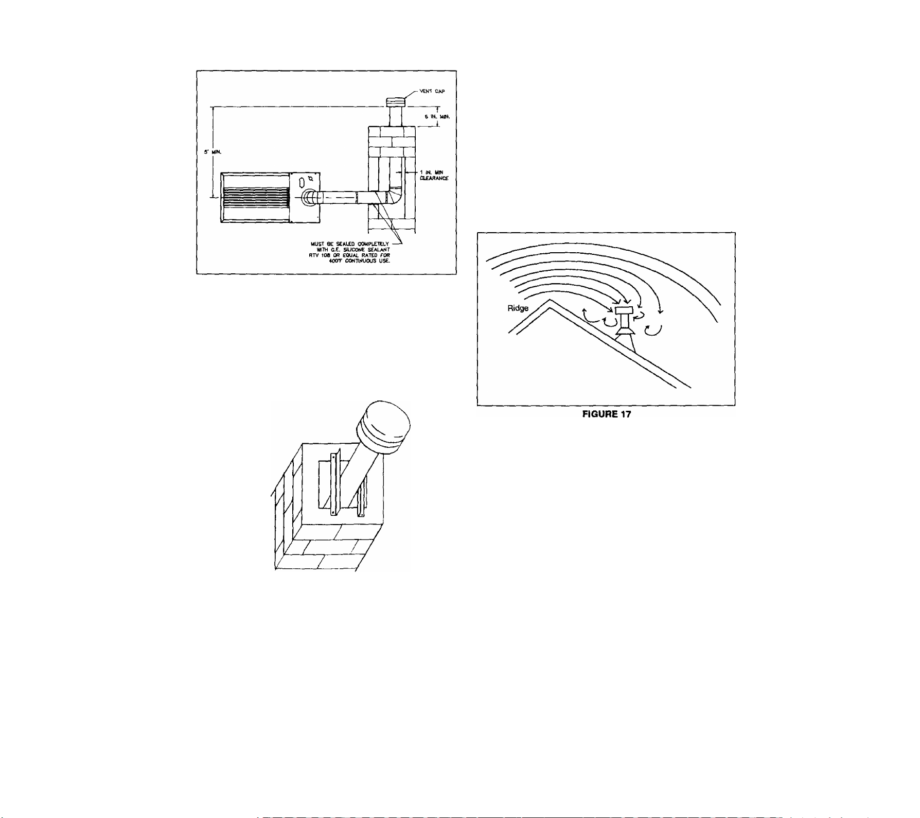
6. Vent termination.
a. Terminate ail verticai vents with a iisted vent
cap or roof assembly unless local codes require
otherwise. See vent cap or roof assembly
manufacturer's instructions. Locate vent termi
nation (vent cap or roof assembly) in an area
without positive wind pressures or eddy currents.
Eddy currents occur when air swirls over roof
peaks. They can cause down-drafts and ad
versely affect vent operation. See Figure 17.
FIGURE 16
WAKNINOi Vent liner muet not block opening
where other epplicncee' vent connector* enter
chimney. Blocked opening* could cau»* com
bustion products to collact In atructur*, r*sutt-
Ing In damag*, Injury or dssth.
WARNINOt Do not uaa unllnad masonry chlm-
naya. Thasa Incraasa risk of condansats forma
tion, which may causa chlmnay to datariorata,
allowing combustion products to collact In
structura, raaulting In damaga. Injury or death.
Some vent terminations or caps protect against
eddy currents and down-drafts, Consult their
manufacturer's instructions. Vent terminations or
caps should usually be at least the same size as
the vent. They may be larger if the installation
warrants.
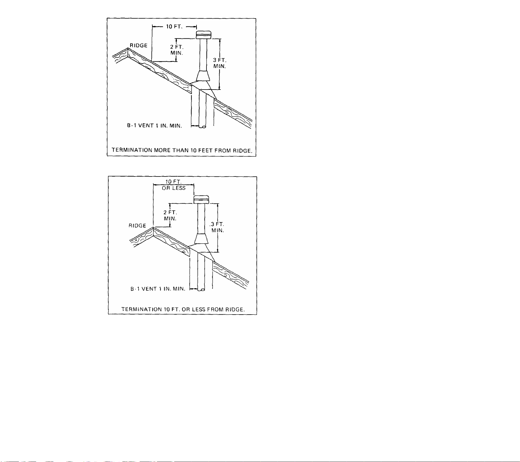
b. Vent systems must end at least five feet above
the highest gas appliance connection. Vent pipe
must extend at least three feet above the point
where it passes through the roof. Vent termina
tion must be at least two feet higher than any
portion of building within ten feet horizontal and
vent termination must be at least two feet higher
than roof peaks within ten feet horizontal. See
Figures 18 and 19. Some vent cap manufactur
ers offer vent caps that allow reduced clearances.
Consult their Instructions.
15
D. Installation.
1. Vent connectors.
Attach vent connector at draft inducer collar. Make
sure flue gasket is in place providing a seat. Use a
minimum of three equally spaced screws around
connection. Connect all other vent pipes using three
equally spaced screws at each joint. Exception is
only when you use Type B1 vent pipe with self
locking connections or high temperature plastic pipe.
WARNINGS Unsecured vent pips connections
may loosen. This can allow combustion products
to collact In structura, resulting In Injury or death.
Install vent connectors without any dips or sags.
Slope them upward from furnace at least f/4” per
foot. To prevent sagging, at each joint support vent
connectors and horizontal portions using hinges,
straps or equivalent. Seal all connections where vent
connectors enter chimney. See Figure 15.
TERMINATION MORE THAN 10 FEET FROM RIDGE
FIGURE 18
TERMINATION 10 FEET OR LESS FROM RIDGE
FIGURE 19
WAftNINGt Failure to properly terminate
vent chimney systems could allow combus
tion products to collect In structure, result
ing In Injury or death.
c. Terminate venting system at least three feet
above any forced-air building inlet within ten feet.
Consider doors, windows and gravity air building
inlets. Locate vent termination at least four feet
below, four horizontal feet from or one foot above
any of these openings.
To avoid blockage, attach vent connector to a ma
sonry chimney above the extreme bottom. For in
spection ease, use thimble or slip joint to make vent
connector removal easy. Firmly attach connector.
Insert all vent connectors into, but not beyond, inside
chimney wall.
2. Vertical vent or chimney systems.
Install vent materials following their listing terms,
manufacturer's instructions, these instructions and
local codes.
A gas vent passing through a roof must extend
through roof flashing, jack or thimble. It must termi
nate above roof surface.
E. Existing vent considerations.
Masonry chimneys previously used for venting solid fuel
or oil burning equipment should be lined with suitable
metal liner. Also provide an accessible clean out per cur
rent National Fuel Gas Code ANSI Z223.1/NFPA 54.1.
1. Inspection of vents (chimneys).
a. Make sure existing vent or chimney is proper
size and construction for appliances that will use
it. The best way to do this is to size as if it were
a new installation. Compare the existing vent to
your calculations and make necessary correc
tions.
b. Examine vent or chimney cleanouts to make sure
they remain tightly closed when not in use. Make
sure vent or chimney passageway is clear and
free of obstructions. Look for evidence of con
densate or deterioration in vent or chimney. Ei
ther of these means an inadequate vent.
c. If you find an inadequate vent or chimney, do
not leave it as is. Repair or replace it. A new
vent must meet these instructions and current
16

National Fuel Gas Code ANSI Z223.1/NFPA 54.
Rabuild a chimney to meet national standards.
MCriON 10 —
TOOLS NIIDID rOR INSTALLATION.
WARNINOi An Inadequate vent or chimney
could allow combuatlon products to collect
In structure, resulting In Injury or death.
d. Sometimes you wiii repiace a common vented
appliance. Make sure common vent size is cor
rect for aJl appliances connected to it. If you re
move a furnace from a common vent without
replacing it, the vent will likely be too large for
remaining appliances. See Venting Addendum.
e. The following steps shall be followed with each
appliance remaining connected to common vent
ing system placed in operation, while other ap
pliances remaining connected to common venting
system are not in operation.
1. Seal any unused openings in common vent
ing system.
2. Visually inspect venting system for proper
size and horizontal pitch and determine there
is no blockage or restriction, leakage, corro
sion and other deficiencies which could
cause an unsafe condition.
3. Insofar as is practical, close all building doors
and windows and all doors between space
in which appliances remaining connected to
common venting systems are located and
other spaces of building. Turn on clothes
dryers and any appliances not connected to
common venting system. Turn on any ex
haust fans, such as range hoods and bath
room exhausts so they will operate at maxi
mum speed. Do not operate a summer ex
haust fan. Close fireplace dampers.
4. Follow Operating Instructions. Place appli
ance being inspected in operation. Adjust
thermostat so appliance will operate con
tinuously.
5. After it has been determined that each ap
pliance remaining connected to common
venting system properly vents when tested
as outlined above, return doors, windows,
exhaust fans, fireplace dampers and any
other gas-burning appliance to their previous
conditions of use.
6. If improper venting is observed during any
of the above tests, common venting systems
must be corrected.
NOTE: Follow current National Fuel Gas
Code ANSI 2223.1/NFPA 54 to correct im
proper common vent operation. Any common
vent resizing must approach minimum size
determined by using Venting Addendum.
ITEM
TOOL DESCRIPTION
HAND TOOLS
A.
1. Carton KnHe
1/4" nut driver
2.
5/16" nut driver
3.
4. 3/8” nut driver
1/4" X 8" straight-
5.
blade screwdriver
#2 X 8" Phillips
6.
screwdriver
7/16" open end or
7.
tubing wrench
2-8" to 14" pipe
8.
wrenches
4" adjustable
9.
wrench
10. 8” Channel-lock
ptiei^
3/16" Allen
11.
wrench
12.
9/64" Allen
wrench
B.
SUPPLIES
13. Pipe thread sealant
suitable for use with
propane (LP) gas
14.
Bottle of soap
solutbn
15.
2-1/8” pipe, manual
shutoff valves
C.
TEST INSTRUMENTS
16.
Volt meter with 50
and 150 volt ranges
17. Clamp around
ammeter with 10 amp
and higher ranges
USED FOR
Furnace removal from
carton
Control box cover
Casing and blower
Blower and motor
mounts
Wire terminals and manifold
pressure adjustment
Components in control box
Main burner orifices
Gas pipe installatbn
Blower wheel set screw
tightening
Strain reliefs
Inlet and outlet pressure tap
plug removal from gas control
Honeywell gas inlet fitting
Gas pipe and controls
Gas leak checking
Gas control inlet and
pressure checking
Electrbal chedt of controls
and power supply
Amp draw of motors and
control check
17

18. 10-turn coil of wire
to fit on ammeter
19. "U" Tube Water
Manometer with O.V
resolution 0“to 15"
W.C. range
20. Slope gauge with
0.01” pressure
measurement taps
and tubing, Oto 1"
W.C. range
Room thermostat heat
anticipator setting
Gas pressure
measurement
Duct work static pressure
furnace. A convenient way to do this when you have
reduced bottom clearance, is to make drip leg by
using a 1/2" to Г NPT Tee, Then install a 1-1/2"
long.l” NPT nipple in Tee with a Г NPT pipe cap to
complete drip leg.
3. When using black iron gas pipe, install an A.G.A.
listed ground joint union between drip leg (sediment
trap) and furnace gas control. Locate ground joint
union to allow easy servicing of burner assembly
and gas control.
4. Install gas pipe to inlet side of furnace gas control.
21. 2 thermometers
with 1 -degree
Fahrenheit
resolution, 50
degrees F to 175
degrees F range
22. Stop watch
23. Torque wrench
(100 inch-pounds)
Temperature rise measured
through lurnace
Gas input meter timing
Proper screw installation
SICTION 11 — INSTALLING GAS PIPING.
Equipment needed: Save time by getting these tools before
you start: Item number(s) 8,12.13 and 14 listed in Section
10.
A. Preparation.
Gas piping must meet requirements of current National
Fuel Gas Code ANSI Z223.1/NFPA 54 and local codes.
Size of pipe running to furnace depends on:
• Length of pipe;
• Number of fittings;
• Specific gravity of gas;
• Input requirements fBtuh) of all gas-fired appli
ances attached to same main supply line.
Refer to current National Fuel Gas Code ANSI Z223.1/
NFPA 54 for correct gas pipe sizing information.
Plan furnace gas supply piping so it will not interfere with
removal of burner assembly, front door or blower door
for servicing.
Always use a pipe thread sealant which is resistant to
propane (LP) gas solvent action. Sparingly apply sealant
to all joints on male threads only, starting two threads
back from end.
B. Installation.
1. Install A.G.A. listed manual shut-off valve in gas
supply line immediately upstream of furnace. Install
1/8" NPT plugged tapping accessible for test gauge
connection. Omit separate, plugged tapping if local
area accepts plugged tapping in gas control inlet.
2. After in-line manual shut-off valve, install a drip leg
(sediment trap) at gas supply line inlet connection to
WARNINGS Do not thread gas pipe too far. Do
ing so may cause gas control to split or crack
which could cause a gas leak or distortion or
malfunction of gas control. Thasa could causa a
firs or explosion resulting in damage, Injury or
death.
5. Isolate gas control from gas supply line pressure
during leak check. Gas supply line test pressure de
termines how you isolate gas control.
WARNINGS At gas supply line, test pressure
equal to or less than 14 Inches W.C. (1/2 PSI).
Isolate gas control from gas supply line by turning
furnace gas control knob clockwise > to off posi
tion. Unexpected surges could damage gas con
trol causing gas to leak, resulting In firs or ex
plosion.
WARNINGS When test pressure la above 14
Inches W.C. (1/2 PSI), completely disconnect gas
control from gas supply line. Failure to Isolate
gas control from test pressure could damage H,
causing gas to leak, resulting in firs or explosion.
6. Use a commercial soap solution made to detect leaks
and check all gas piping connections. Bubbles indi
cate gas leakage. Seat all leaks before proceeding.
WARNINGi Never use an open flams to check
for gas leaks. If a leak doss exist, a firs or explo
sion could occur, resulting In damage. Injury or
death.
Furnace Gas Entry Piping.
1. See below for gas entry holes and knockouts.
a. A 1-1/4* X 2-3/4" knockout in top plate.
b. A 1-1/2" diameter hole and a 1-1/4" x 1-15/16"
knockout in right side of casing.
c. Two 1-5/8" diameter knockouts in left side of
casing.
2. Changing Gas Control Inlet.
You may want to change direction of gas inlet elbow
on gas control. Gas control is shipped for right side
gas entry. If you need top entry, remove the fitting. If
you need left side gas entry, rotate the fitting 180
degrees.
18

a. Use 9/64" Hex Allen wrench to remove tour
screws. Check that O-ring is in bottom of gas
inlet elbow. Rotate elbow to desired position.
WARNINGi Provide furnace with ita own separate elec
trical circuit, means of circuit protection and electrical
disconnect switch. Follow current National Electrical Code
ANSI/NFPA 70 and state and local codes. Failure to pro
vide these shut-off means could cause electrical shock
or fire, resulting In damage, Injury or death.
install proper electrical grounding by attaching grounding
source to green wire conductor in furnace junction box. Fol
low current National Electrical Code ANSI/NFPA 70 and local
codes.
WARNINGS Furnace must have proper electrical ground.
Failure to provide a proper electrical ground could cause
electrical shock or fire, resulting In damage. Injury or
death.
fICTION 13 —
FOLLOWING FIELD WIRING DIAGRAM
HEATING COOUNG
THERMOSTAT MODEL
b. Alternately tighten tour screws to 45 inch pounds
to form a gas tight seal.
c. Use a commercial soap solution made to detect
leaks and check all gas piping connections.
Bubbles indicate gas leakage. Seal all leaks be
fore proceeding.
WARNINOi Never use an open flame to
check for gas leaks. If a leak does exist, a
fire or explosion could occur, resulting In
damage, Injury or death.
3. Allowing tor Electronic Air Cleaners.
Some large electronic air cleaners will interfere with
incoming gas line. Install air cleaner on opposite fur
nace side from gas entry or route gas pipe over top
of air cleaner through one of alternate knockouts.
SICTION 12 —
INSTALLING ILICTRICAL WIRING.
Equipment Needed: Save time by getting these tools before
you start: Item number(s) 2 listed in Section 10.
Select a location for room thermostat that is away from sup
ply and return air registers, on draft-free interior wall, and not
near lights, television, direct sunlight, or other heat sources.
Install thermostat following field wiring diagram in Section
13. Use electrical wiring that meets current National Electrical
Code ANSI/NFPA 70 and local codes. Use Type T (63 de
grees C rise) wire or equivalent. See Section 30 for code
information.
TO 115V 1 PH 60 H2
POWR SUPPLY PER
LOCAL CODES
FIELD WIRING DIAGRAM
FIGURE 21
NOTE: When replacing original wire, use same type, color,
or equivalent wire. Remember to renumber wire ends.
SECTION 14 — ADJUSTING ROOM
THERMOSTAT HEAT ANTICIPATOR
Equipment Needed: Save time by getting these tools before
you start: Item number(s)5,17 and 18 listed in Section 10.
Wire system using field wiring diagram in Section 13.
19

A. Exact haat anticipator setting.
SECTION 1 5 — SEQUENCE OF OPERATION.
Exactly setting heat anticipator helps avoid potential call
backs. If you have any of the following factors, set heat
anticipator to match actual current draw in circuit.
• The system contains controls other than those
specified on wiring diagram;
• The system contains nonstandard (18 AWG) size
thermostat wire;
• The system has longer than a 30-foot distance
between thermostat and furnace.
Follow these steps to exactly set heat anticipator:
1. Use 2-foot piece of 24-guage thermostat wire,
stripped on both ends.
2. Use ammeter capable of reading exact amperage in
0-10 amp range. If it is adjustable, set on 0-10 scale.
3. Wind the 2-foot piece of 24-guage thermostat wire
ten times around one open arm of ammeter. Close
ammeter arms. This will act as a ten times multiplier.
4. Make sure 115-volt power to furnace is on. Connect
ends of wire on ammeter across terminals "R" and
"W" of thermostat sub-base. Follow Figure 22.
■Riermostat Sub-Base Terminals
Ten (10) Turns
>^24 Ga. Wire
See Figure 23 for furnace wiring diagram.
Thermostat calls for heat, energizing electronic ignition lock
out module. Electronic ignition lockout module provides power
to gas control and igniter to light pilot. After proving pilot
flame, inducer relay (IDR) closes, energizing inducer motor.
Inducer motor starts and pressure switch closes, energizing
gas control and time delay relay (TDR). Time delay relay
energizes main blower within 20 to 30 seconds.
NOTE: If system locks out, set room thermostat below room
temperature for at least 10 seconds, then return to desired
setting. To purge gas lines, it may be necessary to operate
furnace through more than one lockout cycle at start-up.
After room thermostat is satisfied, gas control and inducer
relay are de-energized simultaneously. Inducer motor de-en
ergizes and returns pressure switch to normally closed (N.C.)
position. Main blower remains energized through time delay
relay for up to 180 seconds.
SECTION 16 — INSTALLING DUCT WORK,
CAUTION: Install all duct work to meet current standards:
• ASHRAE/NFPA 90, Standard for Installation of
Warm Air Heating and Air Systems;
• State and local codes.
Failure to follow these standards could reduce air flow
or increase air leakage, resulting In reduced system per
formance or furnace damage.
Amprobe ^
FIGURE 22
5.
Read amp draw of furnace circuit on ammeter and
divide by 10. This gives you an exact heat anticipator
setting.
Example:
Meter reading - 9 amos
Divide by 10 turns - 10
Heat anticipator setting « .9 amps
6. Set room thermostat's heat anticipator to this amp
setting. Follow instructions provided with thermostat.
B. Approximate heat anticipator setting.
Find heat anticipator under room thermostat cover. Set
heat anticipator at 0.6 amps. Follow instructions provided
with thermostat.
Properly size duct work based on heat loss and heat gain
calculations. Doing so assures:
• Good heating and cooling installations;
• Potentially fewer callbacks;
• Delivery of required circulating air.
For all furnaces, design duct systems for minimum and maxi
mum external static pressures detailed in Figure 24. See
Section 25 on measuring duct work static pressure.
NOTE: When furnace is installed in an upflow position, air
delivery above 1800 CFM requires both sides of furnace be
used for return air, or a combination of one side and bottom
or bottom only.
Downflow installations use top return or top and side return.
Horizontal installations use end return or end and top return.
20

FIGURE 23
21

EXTERNAL STATIC PRESSURE
(Inches of Water Column)
"INPUT
MINIMUM
MAXIMUM
(BTU/HR)
40,000
60,000
80,000
100,000
120,000
140,000
0.10
0.12
0.12
0.15
0.50
0.50
0.50
0.50
0.20 0.50
0.20
0.50
‘Input is on furnace rating plate on blower door.
FIGURE 24
A. Supply air duct work.
NOTE: Supply air duct (plenum) connection must be the
same size as the furnace supply air opening. Attach to
furnace duct flanges.
If you install furnace in horizontal position with an air
conditioner, design a minimum 18" long transition that
allows free air flow through furnace and cooling coil. Make
sure furnace temperature rise is within range noted on
furnace rating plate. Also, consult air conditioner's duct
work installation Instructions.
Seal supply air duct work to furnace casing, walls, ceilings
or fioors it passes through. End duct work outside furnace
space.
B, Return air duct work.
1. In upflow position, return air duct must be a mini
mum depth of 23-31/32". See Figure 25.
2. In downflow position, return air duct must be a mini
mum 19-7/8" inside depth. See Figure 26.
CASING
WIDTH
14.50
20.50
23.50
BTU/HR"
INPUT
40,000
40,000
60,000
60,000
60,000
80,000
80,000
80,000
80,000
100,000
100,000
100,000
120,000
120,000
NOTE: In upflow position, if bottom return air is not
used, you must attach a solid bottom closure panel
to bottom return air opening. Bottom closure panel is
available from manufacturer as follows:
MOTOR*
H.P.
1/4
1/3
1/4
1/3
1/2
1/4
1/3
1/2
3/4
1/3
1/2
3/4
1/2
BOTTOM CLOSURE
PART NUMBER
4045900
4045901
4045900
4045901
4045902
4045901
4045902
3/4
FIGURE 25
140,000
140,000
3/4
3/4
"See furnace rating plate on blower door.
22
4045903

WARNINOt Failure to install bottom closure
panel could allow combustion products to enter
circulating air stream, resulting In injury or death.
When furnace is installed so that supply air ducts carry
air to areas outside the space containing the furnace,
return air must also be handled by a duct(s) sealed to
furnace casing and terminating outside the space con
taining furnace.
Avoid vent system reverse pressure by running return
air duct work outside furnace space. Seal return air duct
work to furnace casing, walls, ceilings or floors It passes
through. End duct work outside furnace space.
WARNINOt Failure to seal return air duct work could
allow combustion products to enter circulating air
stream through air stream leaks, resulting in Injury
or death.
C. Duct dampers.
You may balance air flow with dampers installed in each
branch run duct and adjust for even temperature
throughout the heated space. For proper furnace opera
tion, make sure:
• Supply air registers and return air grilles are
open;
- Rugs, carpets, drapes or furniture are clear of
registers and grilles;
• Size and shape of supply air plenum is correct;
excess static pressure, adversely affecting furnace and cool
ing system operation.
Follow minimum sizing and quantity recommendations in Fig
ure 27, as well as the air filter manufacturer's.
*GAS INPUT ‘MOTOR FILTERS
BTU/HR H.P. (FIELD SUPPLIED)
40,000
40,000
60,000
60,000
60,000
80,000
80,000
80,000
80,000
100,000
100,000
100,000
120,000
120,000
140,000
140,000
•GAS INPUT and MOTOR H.P. can be found on furnace rating
plate.
1/4
1/3
1/4
1/3
1/2
1/4
1/3
1/2
3/4
1/3
1/2
3/4
1/2
3/4
3/4
3/4
DISPOSABLE AIR
(Two Required)
SIZE
14X25X 1
14X25X 1
14X25X 1
14X25X1
16X25X 1
14X25X 1
14X25X 1
16X25X 1
20 X 25 X t
16X25X1
16X25X 1
20 X 25 X 1
20 X 25 X 1
20 X 25 X 1
20 X 25 X 1
20 X 25 X 1
FIGURE 27
CLEANABLE AIR
FILTERS
(FIELD SUPPLIED)
(One Required)
SIZE
14X2SX 1
14X25X 1
14X25X 1
14X25X1
16X25X 1
14X25X 1
14X25X 1
16X25X 1
20 X 25 X 1
16X25X1
16X25X 1
20 X 25 X 1
20 X 25 X 1
20 X 25 X 1
20 X 25 X 1
20 X 25 X 1
• Number of supply air ducts is correct;
• You consider your own experience and seek as
sistance if needed.
D. Common duct work.
If furnace will share common duct work with a separate
cooling unit, install furnace parallel to or upstream of
cooling unit. This avoids condensation in heating ele
ment. Do not install cooling coil in return air duct work.
With parallel flow, dampers or other means must prevent
chilled air from entering furnace. If dampers or other
means are not in full heat or cool position, furnace or
cooling unit must not operate.
SECTION 17 — SELECTING AND INSTALLING
FILTER CABINETS.
CAUTIONS You must Install air filters to keep these
components clean: blower motor, blower wheel and air
conditioning coll, If there le one. Dirty equipment may
reduce system efficiency or cause erratic control perfor
mance, resulting in damage to blower motor or heat ex
changer and air conditioner (if installed).
Do not install air filters inside furnace casing.
There are no air filters shipped with this furnace. Obtain and
install correct size filters and proper filter frames. Air velocity
must not exceed 300-teet per minute through low velocity
disposable filters.
Air velocity must not exceed 650-feet per minute through
high velocity cleanable filters. Too small a filter could cause
FIGURE 28
23

■ВАСЖ OF nLTER CABINET
AND FURNACE CASING
SIDE OF niTER CABINET
AND FURNACE CASING-
UPFLOW SIDE FILTER CABINET
FIGURE 29
1. Upflow Positions.
a. Upflow position uses a bottom filter cabinet, side fitter
cabinet or return air filter grille (field supplied).
Manufacturer available bottom and side filter cabi
nets provide correct fitter spacing to assure designed
airflow. Field fabricated filter cabinets should allow
1” spacing between filter and furnace.
b. 1. For upflow side return, use a 16x25 filter,
2. For upflow air delivery above 1800 CFM use the
following combinations of return air openings;
1. Bottom only or
2. 1 Side and Bottom or
3. Both sides.
Use appropriate filter cabinets with combinations
listed above.
c. See figures 30A and ЗОВ for floor cut out and filter
size of bottom filter cabinet available from manufac
turer.
FILTIR ОШ1МЕТ
A
13-1/16"
15-1/16"
19-1/16"
19-1/16"
в c
23/32" 14-1/2"
1- 7^52’ 17-.1/2"
23/32" 20-1/2"
2- 7/32" 23-1/2"
UPFLOW FLOOR CUT OUT FOR
BOTTOM FILTER CABINET
FIGURE 30A
Bottom Return Filter Sizes
GAS INPUT
*BTU/HR
40,000
MOTOR
*H.P.
1/4
40,000 1/3
60.000
60,000
1/4
1/3
60,000 1/2
80,000 1/4
80,000 1/3
80,000 1/2
80,000 3/4
100,000 1/3
100,000 1/2
100,000 3/4
120,000 1/2
120,000
140,000
140.000
3/4
3/4
3/4
‘See furnace rating plate located on blower door.
FILTER
SIZE
14 X 25
14x 25
14x 25
14x 25
16 X 25
14x 25
14x 25
16x25
20 X 25
16x 25
16 X 25
20x 25
20x 25
20x 25
20 X 25
20 X 25
24
FIGURE ЗОВ

NOTE: Bottom and side filter cabinets available from
manufacturer have a 1 inch space between furnace
casing and filter for increased filter area. Placing fitter
(field-supplied) directly against furnace bottom or side
will decrease airflow and adversely affect furnace
operation. Allow 1 inch clearance from furnace filter
(field-suf^tied) to furnace.
2. Horizontal Position.
Horizontal position should use an appropriately sized and
installed return air filter grille or duct work air fitter.
3. Downflow Position.
1. Is furnace properly equipped to operate with available
fuel? See Section 2.
2. Is furnace level? See Section 4.
3. Have you cleared away all loose construction and insu
lation materials? See Section 6.
4. Is furnace installed with proper clearances to combus
tible materials? See Section 6.
5. И furnace is in crawl space, is it sufficiently elevated
above the ground? See section 6.
Downflow position furnaces use (2) 16 x 20 filters.
For downflow position, install filter support in return air
plenum Of use return air filter grille. Downflow filter sup
port and filter kit is available from manufacturer.
6. Does furnace have sufficient combustion and ventilation
air? See Section 8.
7. Does vent system meet current National Fuel Gas Code
ANSI Z223.1/NFPA 54 and local codes? See Section 9.
8. Is vent connection securely fastened to draft inducer
collar? See Section 9.
9. Did you completely check gas pipe and controls for gas
leaks? See Section 11.
10. Does electrical wiring follow current National Electrical
Code ANSl/NFPA 70 as well as local codes? See Section
12.
11. Is furnace electrically grounded? See Section 12.
12. Is room thermostat properly installed and heat anticipa
tor set correctly? See Section 14.
13. Is duct work system correctly sized and sealed? See
Section 16.
14. Are air filters in place and correctly sized? See Section
17.
15. Are proper fitter frames or fitter supports installed? See
Section 17.
DOWNFLOW FILTER ARRANGEMENT
FIGURE 31
To inspect, replace or clean air filters, follow Users' Informa
tion Manual instructions.
SECTION 18 CHECKS BEFORE STARTING
FURNACE.
Before starting furnace for the first time, be sure you can
answer "Yes” to each of these questions:
16. On furnace installations above a 2000-foot elevation, Is
furnace derated properly? See Section 23.
SECTION 18 ^ ADJUSTING PILOT.
Equipment needed: Save time by getting these tools before
you start: item number(s) 9,10,14,15,19 and 23 listed in Sec
tion 10.
NOTE; To purge gas lines, it may be necessary to operate
furnace through more than one lockout cycle at start-up.
WARNINGS You must have correct gas supply line and
pilot gas pressures. Correct pressures give proper pilot
Ignition and burner operation. Use e "U" tube water ma>
nometer to measure actual gas pressure. Failure to accu
rately adjust pressure could cause a fire or explosion
resulting in damage, injury or death.
A. Gas supply line pressure.
1. Turn off gas at manual shut-off valve in gas supply
line just ahead of furnace.
2. Remove inlet pressure plug from gas control.
25

3. Make sure valve is in off position, then install 1/8”*
pipe manual shut-off valve in hole vacated by plug.
4. Attach "U" tube water manometer to 1/0"-pipe manual
shut-off valve just installed,
5. Open manual shut-off valve in gas supply line just
ahead of furnace.
6. Open 1/8"-pipe manual shut-off valve leading to "U"
tube water manometer.
7. Turn on all gas appliances attached to gas supply
tine.
8. Whh furnace operating, read gas supply line pres
sure on manometer.
a. Gas supply line pressure must not exceed
10,5 inches W.C. for natural gas.
b. Gas supply line pressure must not exceed
13 inches W.C. for propane (LP) gas.
9. If gas supply line pressure is not within these limits,
call gas supplier.
10. Turn off all gas appliances attached to gas supply
line.
B. Pilot flame adjustment.
Before adjusting pilot flame, confirm that gas supply line
pressure is correct, as explained in paragraph A) above,
then proceed;
3. Disconnect pressure switch, red/yeltow, #7/#8 piggy
back wire from pressure switch, terminal ”N.0.”.
4. Start furnace following Operating Instructions on front
door. Pilot will light; after delay, inducer blower will
come on, but main burners will not light.
5. Pilot flame should cover 1/2” of tip of flame sensor
as shown in Figure 32.
6. If you need to adjust pilot flame, remove pilot adjust
ment cover screw on gas control. Save screw for
reinstallation. Turn inner adjustment screw clockwise
-> to decrease pilot flame; counter-clockwise <- to
increase pilot flame. Install cover screw and tighten
to torque of 5 inch-pounds to prevent gas leakage.
7. Shut off furnace. Connect pressure switch, red/yellow,
#7/#8 piggyback wire to pressure switch, terminal
-N.O.".
8. If you will not be checking gas input now, turn off
gas. Use manual shut-off valve in gas supply line
just ahead of furnace, Remove shut-off valve from
gas control inlet pressure tap. Install pressure tap
plug. Turn on gas.
9. Check pilot adjustment cover screw and gas control
inlet pressure tap plug for gas leaks. Use a commer
cial soap solution made for leak detection.
WARNINOi Never use an open flame to check
for gaa leaks. A gas leak could cause a firs or
explosion, resulting In damags, Injury or death.
1. Open manual shut-off valve located in gas supply
line just ahead of furnace.
2. If necessary, adjust spark gap to 3/18" as shown in
Figure 32. Pilot flame should cover 1/2" of tip of
flame sensor.
3/16 INCH
SICTION 20 — ADJUSTING MANIFOLD
PRiSSURI.
Equipment Needed: Save time by getting these tools before
you start: Item number(s) 9,10,11,15,19 and 23 listed in Sec
tion 10.
WARNINOi Correct manifold pressure Is necessary for
proper ignition and burner operation. Use a "U" tube water
manometer to measure actual gaa pressures. Failure to
accurately adjust pressure could cause heat exchanger
failure, asphyxiation, firs or explosion, resulting In dam*
age, Injury or death.
A. Normal manifold pressures (gas control outlet pres
sures).
<3as. Supply
Natural gas
Propane (LP) gas
Normal
3.5 inches W.C.
10.0 inches W.C.
CAUTIONi Many Installers* sat Propane (LP) manifold
pressure at 11.0 Inches W.C. Do not do this. It could
cause heat exchanger failure or nuisance callbacks.
Check gas supply line pressure first, following instruc
tions in Section 19A.
Connect a "U" tube water manometer to measure
manifold pressure:
FIGURE 32
1. Turn off gas at manual shut-off valve located in gas
supply line just ahead of furnace.
26

2. Remova outlet pressure tap plug from gas control.
3. Make sure shut-otf valve is in off position, then install
1/8”-pipe manual shut-off valve In hole vacated by
plug.
4. Attach "U" tube water manometer to 1/8"-pipe manual
shut-off valve just installed.
5. Turn on all gas appliances attached to gas supply
line.
cause lighting or burning problems on any of the
appliances.
2. Make sure gas control inlet pressure does not ex
ceed 10.5 inches W.C. Use method in Section 19A
to check gas supply line pressure.
3. Make sura all other gas appliances are off. You may
leave pilots on. Start furnace following Operating In
structions on front door or in Users' Information
Manual.
6. Open manual shut-off valve in gas supply line just
ahead of furnace. Start furnace following Operating
Instructions on front door,
7. Open 1/8"-pipe manual shut-off valve leading to ma
nometer.
8. Read manifold pressure on manometer.
9. Make small changes in manifold pressure within al
lowable range (3.2 inches W.C. to 3.8 inches W.C.)
by turning gas control regulator adjusting screw clock
wise -> to increase pressure; turn counter-clockwise
<- to decrease pressure. Make major changes in flow
rate by changing main burner orifice size. See Sec
tion 23.
10. Turn off gas at manual shut-off valve in gas supply
line just ahead of furnace. Install outlet pressure tap
plug in gas control. Turn on gas.
11. Check regulator adjustment cover screw and gas
control plug for gas leaks. Use a commercial soap
solution made for leak detection.
WARNINOs Never use an open flame to check
for gas leaks. A gas leak could cause a fire or
explosion resulting In damage, Injury or death.
4. As furnace warms up, watch gas supply line (gas
control inlet) pressure using "U" tube water manom
eter installed in gas control inlet pressure tap. Natu
ral gas supply line pressure must still not exceed
10.5 inches W.C.
5. After verifying correct gas control inlet pressure, close
shut-off valve in gas control inlet pressure tap. Move
manometer connection to gas control outlet pressure
tap. See Section 20. Open shut-off valve in outlet
pressure tap. Let furnace warm up for 6 minutes.
6. Manifold pressure should be 3.5 inches W.C. Adjust
by removing regulator cover screw on gas control.
Save screw for reinstallation. Turn inner adjustment
screw counter-clockwise <- to decrease manifold
pressure; turn clockwise -> to increase manifold pres
sure. Set correct manifold pressure. Install cover
screw and tighten to torque of 5 inch-pounds to pre
vent gas leakage.
7. Locate gas meter. Determine which dial has the least
cubic feet of gas and how many cubic feet per revo
lution it represents. This is usually one-half, one or
two cubic feet per revolution.
8. With stopwatch, measure time it takes to consume
two cubic feet of gas.
SECTION 21 — CHECKING GAS INPUT.
Equipment Needed; Save time by getting these tools before
you start: Item number(s) 11,14,15,19 and 22 listed in Sectbn 10.
WARNING! Natural gas heating value (BTU/cu.ft.) can
vary significantly, therefore, it Is the installers* responsi
bility to see that BTU Input to furnace Is adjusted prop
erly. Failure to do so could cause heat exchanger failure,
asphyxiation, fire or explosion, resulting in damage, in
jury or death.
Underfiring could cause inadequate heat, excessive conden
sation or ignition problems. Overfiring could cause sooting,
flame impingement or overheating of heat exchanger.
A. Natural Gas.
NOTE; For operations above 2,000 feet elevation, follow in
structions in Section 23.
Before starting natural gas input check, obtain gas heat value
at standard conditions from local supplier.
1. Make sure gas piping is large enough for all appli
ances connected to it to operate at once without
lowering main line pressure. Failure to do so could
27
a. If dial is one-half-cubic foot per revolution,
measure time for four revolutions.
b. If dial is one-cubic foot per revolution, mea
sure for two revolutions.
c. If dial is two-cubic feet per revolution, mea
sure for one revolution.
d. After determining the number of seconds for
two cubic feet of gas to flow through meter,
divide this time by two. This gives average
time for one cubic foot of gas to flow through
meter.
Example:
If it took 58 seconds for two-cubic feet to flow, it
would take 29 seconds for one-cubic foot to flow.
9. a. Use this formula to calculate gas input:
Gas BTU/CU.FT. x 3,600
seconds per/hour
Gas Input =
Seconds for one cubic foot of gas
Btuh

Example:
Gas Input -
Assume it took 29 seconds for one cubic foot of
gas to flow and heating value of 1,000 BTU/
CU.FT.
1,000 x 3,600
124,138 Btuh
29
If you left no other pilots on, this is the furnace
gas input.
b.
If you left water heater, dryer or range pitots on,
allow for them in calculating correct furnace gas
input. A quick way is to allow 1,000 Btuh for a
water heater. Allow 500 Btuh for dryer and 500
Btuh for each range burner pilot.
Example:
If you left gas water heater, dryer, four range
burner pilots and one oven pilot on, allow:
Water heater pilot
Dryer pilot
4 range burner pitot
1 range oven pilot
1.000 Btuh
500 Btuh
2.000 Btuh
500 Btuh
1. Make sure you have correct pilot orifics and main
burner orifices. Be sure that gas piping is large
enough for all appliances connected to it to operate
at once without lowering the main line pressure.
Failure to do so could causa lighting or burning
problems on any of the appliances.
2. Gas control inlet pressure must be between 11
inches and 13 inches for propane (LP) gas. See
Section 19A to check gas supply line pressure.
3. Turn off all other gas appliances. Pilots may be left
on. Start furnace following Operating Instructions
on front door or in Users' Information Manual.
4. As furnace warms up, watch gas supply line (gas
control inlet pressure) using "U" tube water manom
eter in gas control inlet pressure tap. See Section
19A. Supply line pressure must stili be between 11
inches and 13 inches W.C. for propane (LP) gas.
5. After verifying correct gas control inlet pressure,
close shut-off valve tn gas control inlet pressure
tap. Move manometer to gas control outlet pressure
tap. See Section 20. Open shut-off valve in gas
control outlet pressure tap. Let furnace warm up for
6 minutes,
4.000 Btuh
Subtracting 4,000 Btuh from 124,138 Btuh
measured above equals 120,138 Btuh. This
would be the correct furnace gas input after
allowing for pilots left on.
10.
Manifold pressure may be adjusted within the range
of 3.2 inches W.C. to 3.8 inches W.C. to get rated
input. If you cannot get rated input with manifold
pressure within the allowable range, you will need
to change orifices. See Section 23.
11.
Turn off gas. Remove 1/8"-pjpe manual shut-off
valves you used. Install 1/8”-pipe plugs In gas con
trol inlet and outlet pressure taps. Tighten to torque
of 50 inch-pounds. Turn on gas. Check both pipe
plugs for gas leaks. Use a commercial soap solution
made for leak detection.
WARNINOi Never use an open flame to check
for gas leaks. A gas leak could cause a fire or
explosion, resulting In damage, Injury or death.
B. Propane (LP) Gas.
WARNING t Propane (LP) gas Installations do not
have gas meters to double check Input rate. Measure
manifold pressure adjustment with an accurate "U"
tube water manometer. Failure to accurately adjust
pressure could cause heat exchanger failure, as
phyxiation, fire or explosion, resulting In damage,
injury or death.
6. Manifold pressure should be 10.0 inches W.C. +/-
0.3 inches W.C. Adjust by removing regulator cover
screw on gas control. Save screw for re installation.
Turn inner adjustment screw counter-clockwise <to decrease manifold pressure; turn clockwise -> to
increase manifold pressure. Set correct manifold
pressure. Install cover screw and tighten to torque
of 5 inch-pounds to prevent gas leakage.
CAUTIONi Many Installers' set propane (LP)
manifold pressure at 11.0 Inches W.C. Do not
do this. It could cause heat exchanger failure or
nuisance callbacks.
WARNINGS Propane (LP) gas Installsttons do
not have gas meters to double check Input rats.
You must measure manifold pressure adjustment
with an accurate "U" tubs water manometer.
Failure to accurately adjust pressure could cause
hast exchanger failure, asphyxiation, fire or ex
plosion, resulting In damage. Injury or death.
7. Turn off gas before removing the 1/8"-pipe manual
shut-off valves. Install 1/8*-ptpe plugs In gas control
inlet and outlet pressure taps. Tighten to torque of
50 inch-pounds. Turn on gas. Check both pipe plugs
for gas leaks. Use a commercial soap solution made
for leak detection.
WARNINGS Never use an open flame to chock
for gas leaks. A gee leak could ceuee a fire or
explosion resulting In damage, Injury or death.
NOTE: For operation at elevations above 2,000 feet,
follow instructions in Section 23.
28

sicTiON aa — orifici sizi.
See Figure 33 for initial gas orifice sizes as shipped from
factory.
sity of air is reduced, therefore, the furnace should be
derated at the rate of four percent (4%) for aactl 1 >000
feet above sea level. It is the Installers' responsibility
to see that the input is adjusted properly.
Initial Orifice Size
Mnput Natural Gas
BTU/HR ^Orifice Size
All size units
*See furnace rating plate located on blower door.
Check with your local gas supplier to determine heat value
(BTU/CU.FT.) of gas in your area. Depending on your local
heat value and elevation, you may need to adjust manifold
pressure or change orifices to get proper gas input rate.
See Section 23.
2.15mm
FIGURE 33
Propane
Orifice Size
1.30mm
SICTION as — DERATINO FOR HIGH
AiTirUDES.
Equipment Needed: Save time by getting these tools before
you start: ttem number(s) 3,7 and 23 listed in Section 10.
A. Installer responsibility.
For operation at elevations above 2,000 feet the den-
NATURAL GAS-ORIFICE SIZE CHART
if the gas supplier has not already derated the gas
BTU value, derating must be achieved by reducing the
size of the main burner orifices. See Table 34 and 35
for proper sizing. Contact gas supplier for more infor
mation.
Adjustment of the manifold pressure to a lower pres
sure reading than what is specified in Section 20,
Manifold Pressure Adjustment of this manual is con
sidered to be an improper derate procedure. With a
lower density of air and a lower manifold pressure at
the burner orifice, the orifice will not aspirate the proper
amount of primary air into the burner. Insufficient pri
mary air can cause incomplete combustion, yellow tip
ping and quite possibly carbon build-up.
B. New orifice size.
See appropriate chart below to determine new orifice
size.
To accomplish altitude derate, a natural gas orifice kit
containing the natural gas orifices indicated in Figure
34 is available through your supplier. A similar propane
(LP) gas orifice kit is available. Individual orifices are
also available in a convenient lot size. Use only these
orifices to assure proper performance.
Elevation
Gas Up to
Heat^
to
Value 2000
BTU/CU.FT. Feet
2001 3001
to
3000
to
4000
Feet Feet
800-849
850-899
900-949
950-999
1000-1049
1050-1100
NOTE: Shaded orifices above are not included in natural gas orifice kit. They are available separately.
2.25mm
2.20mm
2.15mm
2.10mm
2.20mm
2.15mm
2.10mm
2.05mm
*At standard conditions: 30:0 inches Mercury, 60*’F, Saturated.
2.20mm
2.15mm
2.10mm
2.05mm
2.00mm
4001
to to to
5000 6000
Feet Feet
2.20mm
2.15mm
2.05mm
2.15mm
2.10mm
2.05mm
2.05mm
FIGURE 34
5001
2.20
6001
7000 8000 9000
Feet Feet
2.20mm
2.10mm
2.05mm
2.00mm
2.00mm
1.90mm
PROPANE (LP) GAS—ORIFICE SIZE CHART
Elevation
Gas Up to
Heat*
to
Value 2000
BTU/CU.FT.
Feet
40,000-140,000 1.30mm
NOTE; All orifices above are included in propane (LP) gas orifice kit,
2001 3001
to
to
3000 4000
Feet Feet
1.25mm 1.25mm
4001 5001 6001
to
to to
5000 6000
Feet Feet
1.20mm 1.20mm
FIGURE 35
29
7000
Feet
1.20mm 1.15mm
7001
to
2.15mm
2.10mm
2.10mm
2.05mm
2.05mm
7001 8001
to to
8000 9000
Feet Feet
1.15mm
8001
to
Feet
9001
to
10000
Feet
2.05mm
185mm
9001
to
10000
Feet
1.10mm

C. Changing orifices.
WARNINOz Before changing orifices, turn off
electrical power and gas. Failure to do so could
result In electrical shock or gas leak, resulting In
damage, injury or death.
WARNING! Never use an open flame to check
for gas leaks. A gas leak could cause a fire or
explosion resulting in damage, Injury or death.
15. Check gas input following Section 21.
SECTION 24 — ADJUSTING BLOWER SPEED..
1. Set room thermostat to its lowest or off setting.
2. Turn off electricity at electrical disconnect switch
next to furnace.
3. Turn off manual shut*off valve in gas supply line
just ahead of furnace.
4. Turn gas control knob clockwise -> to OFF posi
tion.
5. Starting with burner farthest from gas control, re
move burner screws and burners. Burners overlap.
Burner farthest from gas control is on top. See Fig
ure 36.
6. Remove original gas orifices.
7. First, hand thread new orifices into manifold. Do
not cross-thread; then tighten to torque of 50 inchpounds.
CAUTION: Heating speed tap should not be reduced
below initial factory setting. Reducing speed tap setting
may result in Inadequate air circulation, and could cause
excessive air temperature rise through furnace. This
could cause high-temperature limit switch to cycle burn
ers on and off. This could reduce furnace efficiency and
shorten life of heat exchanger and blower motor.
1. All models have four blower speeds available for
use.
Motor speed designations are:
#1. High Speed (HI)
#2. Medium High Speed (MH)
#3. Medium Low Speed (ML)
#4. Low Speed (LOW)
2. Determine initial heating and cooling speeds in sys
tem design stage. See Product Data sheet for air
flow data. Depending on test results performed ir'
Sections 25 and 26, you may need to change blower
motor speed.
3. Turn off electricity at electrical disconnect switch
next to furnace.
WARNING: Failure to turn off electrical power
to furnace before changing blower motor speed
could cause electrical shock resulting In dam
age, Injury or death.
8. Replace burners in reverse order from instructions
FIGURE 36
in Step 5,
9. Check burner carryover alignment. They should be
touching but not overlap adjacent burner. Replace
screws.
to. Turn gas control knob counter-clockwise <- to ON
position.
11. Open manual shut-off valve in gas supply line just
ahead of furnace.
12. Set room thermostat to its highest setting.
13. Turn on electricity at electrical disconnect switch
located next to furnace.
14. Check for gas leaks using commercial soap solu
tion made for leak detection.
4. Make blower speed changes at connector block lo
cated at side of blower door. See Figure 37A.
FIGURE 37A
5. Never change the "C" common (WHT) wire.
6. To change cooling speed, black wire is moved to
desired speed. Cooling speed is controlled through
blower motor relay (BMR).
7. To change heating speed, brown wire is moved to
desired speed. Heating speed is controlled through
time delay relay (TDR). Heating speed should not
be reduced below initial factory setting.
30

8. Turn on electricity at electrical disconnect switch
located next to furnace.
SECTION 25 — MEASURING DUCT WORK
STATIC PRESSURE.
Equipment Needed: Save time by getting these tools before
you start: Hern number(s) 20 listed in Section 10.
CAUTIONS High duct work static pressure may cause
low airflow resulting In poor heating performance and
reduced heat exchanger life. Low airflow may also cause
poor cooling performance.
Heating.
a.
Measure duct work static pressure with cir
1.
culating air blower on heating speed. Fol
low instructions below.
Measure air temperature rise with circulat
2.
ing air blower on heating speed. See Sec
tion 26.
Air Conditioning.
b.
1. Measure duct work static pressure with cir
culating air blower on air conditioning
speed. Follow instructions below.
A. Preparing to measure duct work static pressure.
1. Open supply air registers and return air grilles. Make
sure the registers and grilles are free of obstruction
from rugs, carpets, drapes or furniture.
2. Set balancing dampers in supply duct system.
3. Check duct work for obstructions or leaks.
4. Make sure fitters are clean and in place. See Section
17 for filter information,
5. Make sure that blower speed taps are set for proper
heating ar^d cooling. Рог heating operation, initial
speed tap should be set in accordance with Figure
37B. For cooling operation, initial speed tap should
be set in accordance with Figure 38. Refer to Sec
tion 24 for adjusting blower speed.
Air Temperature Rise Range
and Heating Operation Speed Taps
-BTU/HR/Motor
Input/ HP
Air Temperature
Rise Range (*’F)
40,000 / 1/4 50-80
40,000 / 1/3
60,000 / 1/4
60,000 / 1/3
60,000 / 1/2
80.000 / 1/4
80,000 / 1/3
80,000 / 1/2
80,000 / 3/4
100.000 / 1/3
30-60 LO
45-75 ML
45-75 LO
35-65 LO
50-80 MH
40-70 MH
50-80 LO
40-70 LO
55-85 MH
100,000 / 1/2 50-80
100,000 / 3/4
120,000 / 1/2
120,000 / 3/4
140,000 / 3/4
140,000 / 3/4
40-70 ML
45-75
45-75
45-75
50-80
Heating Operation
‘Speed Tap
LO
ML
MH
MH
MH
MH
” These are initial Factory Settings.
— See Furnace Rating Plate for BTU/HR input and
Motor H.P.
FIGURE 37B
2. Measure air temperature rise with circulat
ing air blower on heating speed. See Sec
tion 26.
Air Conditioning Operation Speed Tap Settings
with 0.5" W.C. Ductwork Static Pressure
Air
input /
40,000
40,000
60,000 / 1/4 MH HI
60,000 / 1/3
60,000 / 1/2 —
60,000
80,000 / 1/3 LO ML
80,000 / 1/2
80,000
100,000 / 1/3 LO ML HI HI
100,000 / 1/2 — LO
100,000 / 3/4
120,000 / 1/2
120,000 / 3/4
140,000
140,000 / 3/4
HP
1—1/2 2 2—1/2
/ 1/4 MH HI — —
/ 1/3
/ 1/4 H) HI
/ 3/4
/ 3/4
ML
—
ML
—
—
—
— —
— —
—
— — —
— —
—
—
—
—
— — —
See furnace rating plate for BTU/HR input and motor
H.P.
This table only gives initial speed tap settings for
installations with ductwork static pressure of 0.5”
W.C. figuring 400 CFM per ton of air conditioning.
Ductwork with higher than 0.5" W.C. static pressure
will cause reduced airflow and these speed tap set
tings will not be correct. To determine correct speed
tap settings at ductwork static pressures above 0.5”
W.C., see Product Data Sheet.
FIGURE 38
B. Measuring duct work static pressure.
1. Place slope gauge near furnace where level and
adjust scale to read 0.00 inches W.C.
2. Insert one static pressure tap into supply air transi
tion duct between furnace and cooling coil or in the
supply air plenum for heating only systems. Insert
other static pressure tap in return air plenum. See
Figure 39.
31
3 3—1/2 4
—
MH HI
— — — — —
MH HI
—
— — — —
HI
MH
LO
—
LO
—
—
ML MH HI
— — —
HI
ML MH HI
— ML
MH HI — —
LO
ML HI
LO ML
ML HI
LO
MH HI
— —
MH MH HI
HI —
HI HI
HI
ML HI HI
s
—
—
—
—
—
—

FIGURE 39
A, Preparing to measure air temperature rise.
Follow Steps 1 through 5 in Section 25A of this Manual.
B. Measuring air temperature rise.
Air temperature rise (warm air supply temperature mi
nus cold air return temperature) must be within allow
able air temperature rise range specified on furnace
rating plate and in Figure 37B.
Figure 37B shows heating operation speed tap. Fur
nace is set on this speed tap when shipped from fac
tory.
1. Place thermometer in supply air plenum approxi
mately 2 feet from furnace. Locate thermometer tip
in center of plenum to insure proper temperature
measurement.
2. Place thermometer in return air duct approximately
2 feet from furnace. Locate thermometer tip in cen
ter of duct to insure proper temperature measure
ment.
3. Set room thermostat on highest temperature setting.
Operate furnace 6 minutes. Record supply air and
return air temperatures.
Connect pressure tap attached to supply air transi
tion duct (warm air supply plenum) to positive pres
sure side of slope gauge (bottom of scale). See
Figure 39.
4.
Connect pressure tap attached to return air plenum
to negative pressure side of slope gauge (top of
scale). See Figure 39,
5.
Start blower on cooling speed by jumping terminals
"R" and "G" on 24 volt terminal strip located on
furnace control box.
6.
With blower running, read duct work static pressure
from slope gauge.
NOTE: If air filter location is upstream of return air
pressure tap, duct work static pressure must be
adjusted by subtracting 0.08 inches W.C. to get ac
tual duct work static pressure.
Duct Work
Static Pressure
Duct work static pressure should not exceed 0.5
inches W.C. in order to insure proper volume of air
flow.
8.
Remove jumper wire between terminals "R" and "G"
on 24 volt terminal strip. Remove pressure taps and
seal holes in duct work. Failure to seal holes could
result in reduced system performance.
= Measured Pressure -
0.08 inches W.C.
SECTION 26 — MEASURING AIR
TEMPERATURE RISE.
Equipment Needed: Save time by getting these tools before
you start; Item number(s) 21 listed in Section 10.
4. Calculate air temperature rise by subtracting return
air temperature from supply air temperature.
5. a. If air temperature rise is below maximum tem
perature rise, heating system has sufficient air
flow.
b. If air temperature rise is above maximum tem
perature rise specified in Figure 37B, more
heating air flow ts needed. Change blower
heating speed to a higher setting. Follow in
structions in Section 24 to adjust blower speed.
CAUTIONS Operating furnace above maxi
mum air temperature rise may cause poor
heating performance and decreased heat
exchanger life.
6. Heating speed tap should not normally be reduced
below initial factory setting. Some duct system con
figurations and supply register locations may result
in "cold blow". Setting heating speed tap to next
lower speed may resolve this issue.
7. After making heating airflow adjustments, you must
check air temperature rise following Steps 3 and 4
above to verify that resulting air temperature is within
allowable range.
8. H air temperature rise is still above that specified
on furnace rating plate and in Figure 37B, check
duct work design with a qualified heating engineer.
It may be necessary to resize the duct work.
Recheck air temperature rise after revising duct
system.
9. Set room thermostat to desired setting.
10. Remove thermometers and seal duct work holes.
Failure to seal holes could result in reduced system
performance.
32

SICTIOM 27 » CHICKING CONTROLS.
Equipment Needed: Save time by getting these tools betöre
you start: Item number(s) 3 and 1fi listed in Section 10.
Before leaving the work site, check to see that all controls
are functioning properly.
Follow these steps:
13. Turn off electricity at electrical disconnect switch
located next to furnace. Remove jumper from termi
nal strip, termirwils "R" and "G". Reconnect all room
thermostat wires to original terminal strip, terminals.
See Section 13.
14. Remove "U” tube water manometer from gas control
and replace outlet pressure tap. Turn gas control
knob counter-clockwise <- to ON position.
1. Turn off electricity at electrical disconnect switch
next to furnace.
2. Turn gas control knob clockwise -> to OFF position.
3. Connect a "U" tube water manometer to gas control
outlet (manifold) pressure tap.
4. Set room thermostat to its highest temperature.
5. Turn on electricity at electrical disconnect switch
located next to furnace. Electronic ignition lockout
module should start to spark pilot ignitor, but pilot
burner should not light. Manifold pressure should
remain at zero.
6. Electronic ignition lockout module should spark pi
lot ignitor for given lockout time of module and go
into lockout mode. Lockout time for Honeywell
S8600H is 90 seconds maximum.
NOTE: Honeywell electronic ignition lockout mod
ule will stop sparking whan module locks out.
7. Turn off electricity at electrical disconnect switch
located next to furnace. Turn gas control knob
counter-clockwise <- to ON position. Wait 10 sec
onds for electronic ignition lockout module to reset.
15. Turn on electricity at electrical disconnect switch
next to furnace. With main burners and blower op
erating, block off all return air grilles to restrict return
air. Wait for primary limit control to cycle burners
off.
16. Remove all restrictions from return air grilles. When
primary limit cools, burners should automatically
reignite.
17. Set room thermostat to desired setting.
SRCTION 20 BLOWER TIMINGS.
Equipment Needed: Save lime by getting these tools before
you start; Item number(s) 5 listed in Section 10.
1. Blower on-time setting of heating relay is fixed at
20 to 30 seconds and is not field adjustable.
2. Blower off-time setting is adjustable through a range
of 60 to 180 seconds. Blower off-time is factory set
at 180 seconds.
3. If a shorter blower off-time is desired:
a. Turn off electricity at electrical disconnect switch
located next to furnace.
8. Turn on electricity at electrical disconnect switch
located next to furnace. Pilot should light from spadt
and ignite burners. Wait for main blower to start.
NOTE: To purge gas tines, it may be necessary to
operate furnace through more than one lockout cycle
at start-up.
9. Cycle electrical disconnect switch next to furnace
on and off. Watch at least three ignition cycles. Pilot
should light from spark and light main burners within
10 seconds.
10. Burner flames should look the same with circulation
blower on and off. If not, turn gas control knob
clockwise -> to OFF position.
11. Turn off electricity at electrical disconnect switch
located next to furnace. Disconnect all room ther
mostat wires at control box terminal strip. To start
blower on cooling speed, jump terminal strip, termi
nals "R" and "G". Turn on electricity at electrical
disconnect switch next to furnace.
12. Using a match flame check for air leaks between
bulkhead and blower deck, under burners and up
each side where bulkhead mounts to casing. Tighten
screws until air teaks stop.
b. Remove control box cover and locate heating
relay in control box. Turn the dial counter
clockwise <- to desired setting.
FIGURE 40
4. Install control box cover.
5. Turn on electricity at electrical disconnect switch
next to furnace.
33

SECTION ao — MAINTAINING FURNACE IN
GOOD WORKING ORDER.
WARNINOx Follow these procedures before Inspect
ing furnace.
• Turn room thermostat to its lowest or off set
ting.
* Turn off manual gas shut-off valve.
* Wait at least five minutes for furnace to cool If It
was recently operating.
• Turn off furnace electrical power; failure to do
so could result In injury or death.
WARNING! Use replacement parts listed In parts list.
Failure to do so could cause Improper furnace opera
tion, resulting In damage, Injury or death.
Perform periodic preventive maintenance once before heating season begins and once during heating season. Inspect,
clean, and repair as needed following items:
1. All combustion and ventilation air openings into fur
nace space.
2. All burner combustion air openings.
3. All burners, pilot, collector box, draft inducer as
sembly and complete vent system.
4. All gas pipes leading to furnace.
5. All electrical wiring and connections, including elec
trical ground.
6. All supply air and return air ducts for obstructions,
air leaks and loose Insulation.
7. Blower housing, motor and wheel, air filters, air
conditioning and draft inducer motor. Blower motor
and inducer motor do not require oiling.
A qualified service technician should follow these
steps to remove blower assembly.
a. On downflow furnaces, remove vent pipe inside
furnace.
b. Disconnect wires from low voltage terminal strip
on control box.
c. Remove two screws holding control box to the
side brackets.
d. Remove blower door.
e. Locate connector block beside blower door on
control box side. Remove it by squeezing lock
ing ears of connector block. See Figure 41.
f. Disconnect wires to limit switches on blower
housing.
g. On dual blower wheel models, disconnect wires
to door switch.
h. Remove screws holding blower assembly to
blower deck.
(. 1. Blower assembly will now slide out. DO
NOT damage limit switches on bottom of
blower housing.
2. After cleaning blower assembly, reassemble
in reverse order making sure speed selec
tions are in original positions.
8. Assure the furnace is operating properly and safely.
SECTION 30 — GETTING OTHER INFORMA
TION AND PUBLICATIONS.
These pubiications can help you install the furnace. You
can usually find these at your local library or buy them directly
from the publisher. Be sure to consult current edition of
each standard.
National Fuel Gas Code
National Electrical
Standard for the
installation of Warm Air
Heating and Air
Conditioning Systems
Fireplaces, Vents, and
Solid Fuel Burning
Appliances
For more information, contact these publishers:
ANSI: AMERICAN NATIONAL STANDARDS
INSTITUTE
1430 Broadway
New York, NY 10018
(212) 354-3300
ASHRAE: AMERICAN SOCIETY OF HEATING
REFRIGERATING AND AIR
CONDITIONING ENGINEERS, INC.
1791 Tullie Circle
N.E. Atlanta. GA 30329
(404) 636-8400
NFPA: NATIONAL FIRE PROTECTION
ASSOCIATION
Batterymarch Park
Quincey, MA 02269
(617) 770-3000
34
ANSI Z223.1/NFPA 54
ANSI/NFPA Code 70
ASHRAE/NFPA 90
NFPA211Standard for Chimneys,

INSTALLERS’ MANUAL
NOTES:
I
O
Z
35

o
s
o
VENTING TABLES CATEGORY 1 CENTRAL FURNACES
ACiA
American Gas
Association gama
COPYRIGHT ©1990
GAS APPLIANCE MANUFACTURERS ASSOCIATION
REVISED; JULY,1991
920101
7507-183
36
405740 A

GAMA VENTING TABLES
FOR
CATEGORY I CENTRAL FURNACES
This booklet contains new venting tables designed specifically for use with Category I
central furnaces. These tables are unique, in that, industry wide venting tables now exist for
fan-assisted combustion system central furnaces. Venting tables for these types of appliances
are not contained in the National Fuel Gas Code (NFPA 54/ANSI Z223.1-1988).
All requirements contained in this booklet apply to both Category 1 drafthood equipped
central furnaces as well as fan-assisted combustion system central furnaces. At no time
should a venting system for a listed Category 11, 111, or iV central furnace be sized with these
tables. The National Fuel Gas Code (NFPA 54/ANSI Z223.1-1988) may also be used to size
venting systems for drafthood equipped central furnaces. However, at this time, the National
Fuel Gas Code does not include alternate sizing methods for fan-assisted combustion
systems. Therefore, until engineering data is developed to allow alternate sizing methods
for Category I fan-assisted central furnaces, the enclosed venting tables must be used
for fan-assisted combustion system central furnaces. These tables apply to venting single
appliances and common venting multiple appliances in both metal and masonry chimneys.
The new venting tables were developed by Battelle under contract (GRÎ-5088-245-1728) to
the Gas Research Institute (GRI). The computer program (VENT-11) developed by Battelle
Columbus generated the venting tables in this booklet and this procedure has been accepted
by the American Gas Association Laboratories as an appropriate engineering methodology for
determining venting requirements of Category I central furnaces,
For your information, the general venting requirements listed in this booklet are not
intended to be used as complete installation instructions and represent only a partial list of
venting considerations.
For venting applications that fall outside the parameters of the new venting tables, refer to
the furnace manufacturer's complete installation instructions, the specific vent manufacturer's
complete installation instructions, and state and local codes.
GRI DISCLAIMER
LEGAL NOTICE: This information is, in part, a result of work performed by Battelle under the
sponsorship of the Gas Research Institute (GRI). Neither GRI, members of GRI, nor any
person acting on behalf of either:
a. Makes any warranty or representation, express or implied, with respect to the accuracy,
completeness, or usefulness of this information, or that the use of any apparatus, method,
or process disclosed may not infringe privately owned rights; or
b. Assumes any liability with respect to the use of, or for damages resulting from the use of,
any information, apparatus, method, of process disclosed.
37

VENTING REQUIREMENTS FOR CATEGORY I APPLIANCES
INTRODUCTION
This booklet contains the current definitions,
instructions, and tables necessary to vent todays
modern Category I Gas Fired Appliance. A variety
of definitions of new terms describing today's gas
appliances are included to supplement the actual
venting tables which have been generated to
correctly vent various combinations of Category I
Appliances using Type B or single*wall metal vent
connectors attached to Type B vents or masonry
chimneys. Tables are also included covering similar
venting material combinations when applied to
common venting arrangements of two or more
appliances.
Finally, a series of examples are presented
demonstrating how the vent tables are used to
size the vent connector and the vertical vent for a
variety of typical applications.
I I. DEFINITION OF TERMS
Tan Assisted
Combustion
System"
An appliance equipped with an
integral mechanical means to
either draw or force products of
combustion through the
combustion chamber and/or
heat exchanger.
"FAN Min"
refers to the minimum
appliance input rating of a
Category I appliance with a fanassisted combustion system
that could be attached to the
vent.
"FAN Max"
refers to the maximum
appliance input rating of a
Category I appliance with a fanassisted combustion system
that could be attached to the
vent.
"NAT Max"
refers to the maximum
appliance input rating of a
Category I appliance equipped
with a drafthood that could be
attached to the vent. There are
no minimum appliance input
ratings for drafthood-equipped
appliances.
"FAN+FAN"
refers to the maximum
combined input rating of two or
more fan-assisted appliances
attached to the common vent.
"FAN+NAT" refers to the maximum
combined input rating of one or
more fan-assisted appliance
and one or more drafthoodequipped appliance attached
to the common vent.
"NAT+NAT" refers to the maximum
combined input rating of two or
more drafthood-equipped
appliances attached to the
common vent.
"NR" means not recommended due
to potential for condensate
formation and/or pressurization
of the venting system.
"NA" means not applicable due to
physical or geometric
constraints.
DraftHood A device built into an appliance,
or made a part of the vent
connector from an appliance,
which is designed to (1)
provide for the ready escape of
the flue gases from the
appliance in the event of no
draft, backdraft, or stoppage
beyond the drafthood, (2)
prevent a backdraft from
entering the appliance, and (3)
neutralize the effect of stack
action of the chimney or gas
vent upon the operation of the
appliance.
Vent
A passageway used to convey
flue gases from gas utilization
equipment, or their vent
connectors, to the outside
atmosphere.
Vent Connector The pipe or duct which
connects a fuel-gas burning
appliance to a vent or chimney.
Flue Collar
That portion of an appliance
designed for the attachment of
a drafthood, vent connector, or
venting system.
Categorized
Vent Diameter
The minimum vent diameter
permissible for Category t
appliances to maintain a
nonpositive vent static pressure
when tested in accordance with
nationally recognized standards.
38

) ) I. GENERAL VENTING REQUIREMENTS
All requirements contained in this document apply
to both Category 1 draft hood equipped and fan-
assisted combustion appliances. At no time should
a venting system for a listed Category 11, 111, or IV
appliance be sized with these Tables. The
alternate sizing methods described in the National
Fuel Gas Code (NFPA54;aNS1 Z223.V1988) may
also be used to size the venting system for a
drafthood equipped appliance. At this time,
alternate sizing methods have not been
developed for tan-assisted appliances. Therefore,
until engineering data is developed to allow
alternate sizing methods for Category I fanassisted appliances, the vent tables must be used.
1) The venting tables included in this instaiction
apply to vents and chimneys internal to the
structure below the roof tine. Exterior
chimneys or vents not enclosed by the
structure or a chase below the roof line may
experience continuous condensation
depending on locality. Consult local gas
utility, appliance manufacturer and/or local
codes. A chimney with one or more sides
exposed to the outside of the structure is
considered to be an exterior chimney. A
Type B or listed chimney lining system
passing through an unused masonry chimney
flue is not considered to be exposed to the
outdoors
2) If the vent or connector size determined from
the tables is smaller than the appliance
drafthood outlet or flue collar, the smaller size
may be used provided:
^ The total vent height "FT is at least 10 FT.
3) Single appliance venting configurations with
zero lateral lengths, Tables 1 & 2, are
assumed to have no elbows in the vent
system. For all other vent configurations, the
vent system is assumed to have two 90®
elbows. For each additional 90® elbow, or
equivalenr beyond two, the maximum
capacity listed in the venting table should be
reduced by 10 percent (0.90 x maximum
listed capacity).
* Two 45® elbows are equivalent to one 90® elblow.
4) The common venting Tables 3, 4, 7, & 8 were
generated using a maximum horizontal vent
connector length of 1 1/2 feet (18 inches) for
each inch of connector diameter as follows:
CONNECTOR DIAMETER
MAXIMUM HORIZONTAL
CONNECTOR LENGTH
(INCHES) (FEET)
3
4
5
6
4 1/2
6
7 1/2
9
7 10 1/2
8
9
12
13 1/2
10 15
12 18
14
16
21
24
18 27
20
30
22 33
24
36
b) Vents or connectors for appliance
drafthood outlets or flue collars 12
inches in diameter or smaller are not
reduced more than one table size (e.g.
12 inches to 10 inches is a one size
reduction).
c) Vents or connectors for appliance
drafthood or flue collars above 12
inches in diameter are not reduced
more than two table sizes (e.g. 24
inches to 20 inches is a two size
reduction).
d) The maximum capacity listed in the
tables for a fan-assisted appliance is
reduced by 10% (0.90 x maximum
capacity).
e) The drafthood outlet is greater than 4
inches in diameter. Do not connect a 3
inch diameter vent or connector to a 4
inch diameter drafthood outlet. This
provision does not apply to fan-assisted
appliances.
The vent connector should be routed to the
vent utilizing the shortest possible route.
Connectors with longer horizontal lengths than
those listed above are possible under the
following conditions:
a. The maximum capacity (Fan Max. or Nat
Max.)of the vent connector shall be
reduced 10% for each additional multiple
of the length listed above. For example,
the maximum length listed above for a 4
inch connector is 6 feet. With a connector
length greater than 6 feet but not
exceeding 12 feet, the maximum capacity
must be reduced by 10% (0.90 x maximum
vent connector capacity). With a
connector length greater than 12 feet but
not exceeding 18 feet, the maximum
capacity must be reduced by 20% (0.80 x
maximum vent capacity).
39

b. The minimum capacity (Fan Min.) shaH be
determined by referring to the
corresponding single appliance table
(Tables 1 and 2). In this case, for each
appliance the entire vent connector and
common vent from the appliance to the
vent termination would be treated as a
single appliance vent, as if the other
appliances were not present.
5) If vent connectors are combined prior to
entering the common vent, the maximum
common vent capacity listed in the common
venting tables must be reduced by 10%. the
equivalent of 1 (one) 90® elbow (0.90 x
maximum common vent capacity). See Figure
11 The horizontal length of the common vent
connect or manifold (L) should not exceed
1-1/2 feet (18 inches) for each inch of
common vent connector manifold diameter.
6) If the common vertical vent is offset as shown
in Figure 8. the maximum common vent
capacity listed in the common venting tables
should be reduced by 20%, the equivalent of
2 (two) 90® elbows (0.80 x maximum common
vent capacity). The horizontal length of the
offset shall not exceed 1 1/2 feet for each
inch of common vent diameter.
GAS VENT TERMINATION TABLE
ROOF PITCH
FLAT TO 7/12
OVER 7/12 TO 8/12
OVER 8/12 TO 9/12
OVER 9/12 TO 10/12
OVER 10/12 TO 11/12 3.25 FEET
OVER 11/12 TO 12/12
OVER 12/12 TO 14/12
OVER 14/12 TO 16/12
OVER 16/12 TO 18/12
OVER 18/12 TO 20/12 7.5 FEET
OVER 20/12 TO 21/12
* THIS REQUIREMENT COVERS MOST INSTALLATIONS
MINIMUM HEIGHT
1.0 FEET *
1.5 FEET
2.0 FEET
2.5 FEET
4.0 FEET
5.0 FEET
6.0 FEET
7.0 FEET
8.0 FEET
7) The common vent diameter must always be at
least as large as the largest vent connector
diameter. All interconnection fittings must
also be the same size as the common vent.
8) Type 6 gas vents shall terminate above the
roof surface with a listed cap or a listed roof
assembly in accordance with the terms of their
respective listings and the vent
manufacturer's instructions.
VENT CAPS 12" AND SMALLER
Listed gas venting systems using listed vent
caps 12" and smaller in size may terminate in
accordance with the VENT TERMINATION
TABLE. (SEE FIGURE 1)
VENT CAPS LARGER THAN 12"
Listed ve/it caps larger than 12" must be
located at least 2 feet above the highest point
and at least 2 feet higher than any portion of a
building within a horizontal distance of 10
Feet. (SEE FIGURE 2)
9) Use sea level input rating when determining
maximum capacity for high attitude installation.
Use actual input rating for determining
minimum capacity for high attitude installation.
40

10) No portion of the venting system can extend
into, or pass through any circulating air duct or
plenum.
11) All vent pipe passing through floors, walls,
and ceilings must be installed with the listed
clearance to combustible materials and be fire
stopped according to local codes. In the
absence of local codes, refer to NFGC
(2223.1)
12) Vent connectors serving Category 1
appliances shall not be connected to any
portion of mechanical draft systems operating
under positive pressure such as Category 111
or IV Venting Systems.
13) A Category I appliance must never be
connected to a chimney that is servicing a
solid fuel appliance. If a fireplace chimney
flue is used to vent this appliance, the
fireplace opening must be permanently
sealed.
14) A vent connector shall be supported without
any dips or sags and shall slope a minimum of
1/4 inch per lineal foot of connector, back
towards the appliance.
15) Vent connectors shall be firmly attached to
drafthood outlets or flue collars by sheetmetal screws or other approved means,
except vent connectors of listed Type B vent
material which shall be assembled in
accordance with the manufacturer's
instructions. Joints between sections of
single wall connector piping shall be fastened
by sheet-metal screws or other approved
means,
13) For single appliance vents:
a) If the vertical vent or tile lined chimney has a
larger diameter or flow area than the vent
connector, use the vertical vent diameter to
determine the minimum vent capacity and the
vent connector diameter to determine the
maximum vent capacity. The flow area of the
vertical vent, however, shall not exceed 7
times the flow area of the listed appliance
categorized vent area, drafthood outlet area
or flue collar area unless designed in
accordance with approved engineering
methods. See Table 9 for calculated areas.
b) For multiple appliance vents:
The flow area of the largest section of vertical
vent or chimney shall not exceed 7 times the
smallest listed appliance categorized vent
area, flue collar area, or draft hood outlet area
unless designed In accordance with approved
engineering methods. See Table for
calculated areas.
Maximum vent or tile lined chimney flow area = TTfD*)^ x 7
4
* Drafthood outlet diameter, flue collar diameter, or listed
appliar^ce categorized vent diameter.
c) In no case, shall the vent connector be
upsized more than 2 consecutive table size
diameters over the size of the drafthood
outlet, flue collar outlet, or listed apppliance
categorized vent. Example: An appliance
with a 4 inch diameter flue outlet collar or
drafthood outlet cannot be vented with a
connector diameter larger than 6 inches.
16) When the vent connector used for Category 1
appliances must be located in or pass through
a crawl space or other area which may be cold,
that portion of the vent connector shall be of
listed double-wall Type B vent material or
material having equivalent insulation qualities.
17) The entire length of sirigie wall metal vent
connector shall be readily accessible for
inspection, cleaning, and replacement.
18) For appliances with more than one input rate,
the minimum vent or connector (Fan Min)
capacity determined from the tables shall be
less than the lowest appliance input rating
and the maximum vent or connector (Fan or
Nat Max.) capacity determined from the tables
shall be greater than the highest appliance
input rating.
20) Masonry chimneys used to vent Category I
central furnaces must be either tile-lined or
lined with a listed metal lining system or
dedicated gas vent. Unlined masonry
chimneys are prohibited. (See Note 1).
21) A fan assisted furnace may be common
vented into an existing masonry chimney
provided:
a. The chimney is currently serving at least
one drafthood equipped appliance.
b. The vent connectors and chimney are
sized in accordance with Tables 7 & 8.
SINGLE APPLIANCE VENTING OF A FAN
ASSISTED FURNACE INTO A TILE LINED,
MASONRY CHIMNEY IS PROHIBITED, THE
CHIMNEY MUST FIRST BE LINED WITH
EITHER TYPE B VENT SIZED IN
ACCORDANCE WITH TABLES 1 OR 2 OR A
LISTED, SINGLE WALL, METAL LINING
SYSTEM, SIZED IN ACCORDANCE WITH
NOTE 22.
41

22) Listed, corrugated metallic chimney liner
systems in masonry chimneys shall be sized
by using Tables 1 or 2 tor dedicated venting
and Tables 3 or 4 for common venting with
the maximum capacity reduced by 0.20%
(0.80 X maximum capacity) and the minimum
capacity as shown in the applicable table.
Corrugated metal vent systems installed with
bends or offsets require additional reduction
of the vent maximum capacity (See Note 6).
27) Numbers followed by an asterisk (*) in Table 6,
indicate the possibility of continuous
condensation, depending on locality. Consult
appliance manufacturer, local serving gas
supplier, and/or authority having jurisdiction.
28) In a single run of vent or vent connector, more
than one diameter and type of pipe are
permitted to be used, provided that all the size
are permitted by the tables.
23) For multiple units of gas utilization equipment
all located on one floor, available total height
"H" is measured from the highest drafthood
outlet or flue collar up to the level of the cap or
terminal. Connector rise "R" is measured from
the drafthood outlet or flue collar to the level
where the vent gas streams come together.
(Not applicable to multi-story).
24) For multi-story installations, available total
height for each segment of the system *'H" is
the vertical distance between the highest
drafthood outlet or flue collar entering that
segment and the centerline of the next
higher interconnection tee (See Figure 13).
25) The size of the lowest connector and of the
vertical vent leading to the lowest
interconnection of a multi-story system must
be in accordance with Table 1 OR 2, for
available total height "H" up to the lowest
interconnection (See Figure 14).
26) Common vents in multi-story systems shall be
type B when used in multi-story systems and
have no offsets.
TYPICAL VENTING APPLICATIONS
29) If the desired vent height and connector rise
and/or lateral are between the table entries,
linear interpolation is permitted for calculation
of the permissible appliance input ratrings.
Extrapolation beyond the table entries is not
recommended. (See Example 7)
30) All combinations of pipe sizes, single-wall, and
double-wall metal pipe are allowed within any
connector rur\(s) or within the common vent
provided ALL of the appropriate tables permit
ALL of the desired sizes and types of pipe, as
if they were used for the entire length of the
subject connector or vent. I! single-wall and
Type B double-wall metal pipe are used lor
vent connectors, the comnrion vent must be
sized using Table 4.
31) Locate draft hood outlet or flue collar of
smallest input appliance closest to or under
common vent.
32) When vent table permits more than one
diameter of pipe to be used for a connector or
vent, the smallest permitted diameter should
be preferred.
Table 1 should be used when Type B vent is
used for both the vent connector and the
vertical vent.
Table 2 should be used when a single-wall
metal vent connector is attached to Type B
vertical vent.
42

Tabi* 3 should be used when Type 6 vent
connectors are attached to a Type В common
vent.
Table 4 should be used when single-wall
metal vent connectors are attached to a Type
В common vent.
43

TabI« 5 shall be used when a Type 6, doublewait venl tx>nnector is attached to a tile lined
masonry chimney.
Table 6 shat) be used when a single-wait metal
vent connector is attached to a tile lined
masonry chimney.
FIGURE 9
FIGURE 10
44

VENT TABLES
Capacity of Type B Double-Wall Vents with Type B Double-Wall Connectors
TABLE 1
3”
Height Laterai
H L FAN
(ft)
6 0 0 78 46 0 152 86 0
8
10 0
15
20 0
30 0
50
100 0 NR
Min
(ft)
2 13 51
4 21
6 25 46 32 36 91 61 47
0 0 84 50 0 165 94 0
2 12 57 40
5 23 53 38
8 28
12
2
23 57 40
5
30
10
0
2
11 69 48 15 136 93 20
5
22
10
29 59 41 40
15
35
2
10 75 51
5 21 71
10 28
15 34 58 40 46
20 48 52
2
5
21
27
10
15 33 64 NR
20 56 58 NR 53
30 NR
0
2 8 86 61 11 183 122
5 20
26
10
15 59 70 NR 42 158
20 NR
30 NR
NR
2
5 NR
10 NR
15 NR NR
20
NR NR
30
NR NR
50
NR NR
NAT FAN NAT FAN
Max
Max Min Max
36
34 30 94
49
35 39 98
49
0
88 53 0 175
61 42 17 118 81 23 194 129 26 289
51 36
94 58
0
65
45 30
53
37 48 112 76
97
0
0 100 64 0
9
0 101
61 0 202
48 29
64
44 38 133
35
81 56 13 166
77 54 28 160 108
50 37
70
NR
NR
67 0 216
NR
82
76 NR 35 168 114 45
NR 50
NR
NR 69 131
NR
NR NR
NR
NR
NR NR
NR
NR
NR
NR
NR
NR NR
4"
Appliance Input Rating in Thousands of Btu Per Hour
Max
18 97 67
64 39 153 103 50
16 109 75
103
32
32 113 77
41 104
0 191 112 0
14
55 116 78
71 42 171 115 53
66
100 0 295 166 0
70 54 176 115
130
87 39 219 142 49
121 82
119
100
149
143
96
89
124
84
213
128 0
m
150 102 48
44 141
73 113 NR
27
0
10 194 NR
26
33 182 NR
40 174
47 166
NR NR
96
90 66 237 154 80
132
134
177 319 35
NR
149 NR
NR
218 NR
189 NR
NR
NR
NR
NR
NR
Sen/ing a Single Category I Appliance
Vent and Connector Diameter - D (inches)
5"
Min
27
25
51 164
41 187
51 206
61
18 250 166 20
38
50 229
59 217 142 73 337 217 94 481 308
69 206 134 84
14
36 275 176 45 421 273 58 600 385
57
88
14
54 287 180 66
63
84
12
33 347
43
50
59 311
78 290
NR NR NR 147 428
NAT
Max MaxMax
Max
141
251
157 105
100 59 223 149 78
149
276 155 0 415 235
178 120 28 263 180
109
124 52
327 187
226
150 22 339 225 38
135
195 128 76 301 198 98 429 275 115
0 349 202 0 540 307 0
242 160 47 367 241 62 519 337 73 697
150 62 351 228 81 499 321 95
374 220 0 587 336 0
283 185 18 432 280
171
262
163 70
249
214 NR 104
0 397 232 0
320 206 15 497 314
200 43 487 308
312
190 56 471
299
275 169 76 440 278
250 NR 99 410 259
0 407
NR
354
NR
NR
335 NR 53
321 NR
NR
NR
6" 7" 8"
FAN NAT
375 205
0
32 232
64 247
67 267
0 502 285 0
64 315
59 405
0 665 400 0 997
13
40
62
71
92
157
227
153
255
173
165
447
255
195
280
188 68
175 88
330 217 64 463
208
377
249
206 107
322
261 77 580 371
389 249
237
374
346 219 131
633
455
566
557 369 52
542
528 353 80
513
483 NR 115
102 542 343 119 743 473 139 977 628
363 0
298
288
123 605
375
361
344
180 651 405 197 944
NR
I
FAN NAT FAN NAT FAN NAT
Max
Max
0 524 285 0 698 370
44
66 316
42 365
70
84
40 402
84 445
33 531 346 41
27 613
90 560 357 105
22 715
55 702
73 681 426 86
85 662 413
97
18
68
90
217
321
211
310 205 93 413
583
0
320 0 780 415 0 1006 537
247
356 237
347 227
0 631 345 0
273
392
263
376
245
716
390
475
316
300
288 99
776
430 0 1057 575
464
295
853
475 0
394
507
321 149 702
518 0 1297 708 0
932
445 26
438
642 401 113 888 556 131 1176 722
376 141 844
560
831 510 21 1155
820 504 60 1141
801 493 80 1118 679 94 1492 910
782 482 93 1095
471
763
726
449 131 1029 627
Max
Min
53
79 419 279
50 483
83 473
99 463
48 533
81 522
104 504 330 122.651
45 633 414
76 620
111 654
125 634 410 145 830
33
69
91
65 960 605
100
105 1073
Max Min
285
425
273 110
322 60
313 99
303
847
450 0
355
346
0 970 525 0 1253 682
403
600 386 116
373 134 755
580
470
711
460 86 902 599
443
675
427
650 0
1173
826 535
811 524
788 507 107
490 124
765
444 17!
615
975
935 589 101 1230 773
911 572
522
0 1411
770
700
692
666
653 122 1438 880
575
9"
Mix ftax
897
0
470
63 543 370
536
93
117 596 396
57
95
53
90 800
50 917 612
112 877 576
129 853
42
82 1055
33 1276 813
77
117
161
25 1536 935
71
109
149
217
362
530
354
619 418
607 407
1096
585
684
457
671
446
427
815 544
529
777
507
491
0 1384 752
557
537
855
1548
700
1072
688
668
1028
648
1002
594
929
1730 952
1259 798
747
1203
670
1125
0
1040
1908
926
1519
895
1465
1387 849
787
1288
45

VENT TABLES
Capacity of Тура В Doubla-Walt Vants whh Тура В Doub(a-Wall Connectors
TABLE 1 <Conrd)
1<T 12"
Heigtu Lami Í
L
H
(ft)
6
в
10
15
20
30
SO
100
___
(ft)
0
73
2
4
110 661
6 m 661 435
0 0 1261 660 0 1838 970 0
г 71
5 113 738 503
137
i
0
6B
2
112
5
10 142
0
<3 1019 675 86 1493 985
2
S 103 1003 660 140
10 135
IS
153
0 0 1756 930 0 2637 1350 0
2 59
3 101 1133 738
iO 130 1103 710 172
ISO
15
167
20
0 0
2 54 1351
5 96
10 125
13 143 1272 807
20
160
30
193 1189 745 246
0 0
41 1620 1010
2
5 90
10
IIS
IS
136
20 ISl 1505 924 19S
30 183
0
2
30
3
82
10 108 1923 1142 142 2961 1775 180
IS 126 1892
141
20
30 170
241 16»» 1000 292 2657 15S0 350
50
NAT PAN NAT FAN
PAJ* -
Mm
№
1121 570 0 1643 850 0
0
675 455 103
770 515 9« 1124 745 13Q
746
1377
0
832 560 93 1244 850
839
»17
0
1596 »40
977 635 177
953 610 202 1418 905
1130
107»
1032
1977 1060
1332
1301
1143
2231 1193
1600
1567
1536 94» 177 2327 1437
1446
0
2491
1973
1935
1861
1802
Min
Mtt
147
445
171
134
490 180 1097
• m
547
149
1«7
525
753
81
135
6»»
195 1609
663 217 1371
74
865
»51 127 1981
164 1944 12S4
129
187 1908 1220
207 1873
784
66
996 US
154
972
■76 232
1310 0 3923 2050 0
44
1170
107 3002 1803 136
1159
1124
Ш 2920 1747 206
1107 181
1071 213 2803 1663 265
Mm Mn
9»2 650
973 640 191
967
630 219
ino 733 199
720 231
0
2036 1060
829
1229
1204 795 23»
0
2380 1240
967 182
1476
1446 936 227
1694 noo 107
1674
1079
1641 1045 220
1018 24»
990 273
3004 1550 0
0
2004 1310
1U9
1185
1807 1130
3441
0
1825
2431
1513
2406
1495
2366
1466
22U
1408
2214
1349 287
302? 1820 72
2880
1719 226
Serving a Single Category I Appliance
V«nt ind Connector Diameter - D (tnchct)
I*- 16"
Appliance Inpnt Ballni In Tliantanda of Bln Per Hoar
NAT FAN NAT
Mb
Mn Mm
2267
138
124
192
114
257
174
164
209
237
260
305
151
196
222
244
98
86
1170 0
1346
»90 П8 1769 mo 223
1338
880 242 1761 1160
1330 870 276 1733 П50
2571 1320
1543 lOZQ 168 2030 1340 212
1328
1010 231 2013 13» 311
1514
1000
0
2825 1430 0 3742 1923 0 4712 2450
1713 П30 161 2236
nos
1696
1669 10»0 298
0
3323 1720 0
1350
2062
2041 1327
2009 1289 283
1976 1230 318
3701 1900
1320
2343
2320 1498 219 3071 1978 270
1460 273
2282
2245 1425 306 2988 1910
2210 1390 335 2948 1880
4232 2170 0 5725 2920 0 7420
2786 1800 127 3696 2380 159
2759 ms 206 3666
2716 1733 259 3617 2300 316 4647 2970
2674
1692 292 3570 22»
2633 1650 319
1585
2555
4934
0
2550
3409 2125
3380
2102 191
3332
206* 243
3285 2026
3239 1987
3150 1910
5729 2950 0
4313 2350
4282 2531
4231 2500 223
4182
2*69 252
4133
2438.
4037
2375
3856
2250 415 S2B9
Mu Mu Mb
Mm
2983 13» 0 3802 I960
0 3399 1740 0 4333 2220
2000 1320
289
2238 1461 300 2849
24Э
2209
2270
4423
147
2719
229
2696
2659
2623 1675
4941
0
139 3097 2000
2520 0 6376 3250
3029
2350 252 4701 3020
2200
3523
369 3433
113
274
300
347
93
172
277 3619 3331 330
319
2130 440 4442 2785
0 6711
3440
4354 2840 141 3864
4520 тъ
4464
2767 295
4409
4356 2675 361
4253 2631 412 3523
7914 4050 0 10483
5834 3500 120
5797
3737 3434
567»
5503
FAN NAT
300 2242 1473
341 2235 1470
354
1480 202 2168
364
1430
1770 186
1748
1712 346 3402
0 5678
283
383 3363 2150 479
175
334
1940
372 3835
404
354 4394 2920
384
0 8Л4 4460
234
3»
2721
3475 208
268
30* 7409
3392
3267
378
3100 486 6956 4050
ir
Mu
Mu
2250 1480
2384
1700
2363
1683
2532 1670
1890
1871
1840
2818
2900
3467
2260
2235
3442
2193
2370
3953
2544
3926
2500
3880
2465
2430
3791
3770
4734
3050
2870
4342
3670
5826 3639
3585
5763
5701 3534
5641
3481
3431
5300 0 13434
4600
7591
4366
7548
7478 4509
4451
7341 4394
7209 4279
vr
- PAN_
296
390
437
278
398 3180 2090 476 3863
264 3536
382
459
239
355 4278 2777
432
220
337
413
459
495
199
312
386 5803 3739 456
431
467
NAT
Mb
Mu Mb
Mm
4721 2430 0 3737
0
2782
1850 360
2774
1835
2767
1820
5387 27»
0
3196
2110 336
4»
3163 2070 537 38» 25» 630 4602
5«5 3050 0
0
2340 319 4322 2840
3536
2318 458
3504
2280
0 7099 3620 0 8665 4410
4304
2800
4234
2739
2700
4192
7988
0
4060 0 9785 4980 011733
3200 269
4916
3174 403
4885
3130 489 5896 3830
4835
3C90
4786
4737 3030 585 3792 3760
0 9341 4750
5900 3810 241
3783
5863
5744 3695
5686 36» 548
22"
- FAN
469
323 3363
546
290 5232 Я10 346 6251
426
SIO 5159 3343
564
341 5844
373 7155 4622
307 7026 4527
NAT FAN
Mu Mu
29»
337?
2220 426 4030
3370 221S 535 4023
2210 618 4017
0 6533 3360
3882 2560
2545
7254
3710 0 8682
430)
2818
4268 7П80
5204
3385
5115 3300 663 6129
3983
3910
3880 475 7119
59»
3795
011483
5850
7194
4650
7090 4574
6964
4480
540 5574 3365 635 6842 4375
on 129 5635
171 7339 4630 209 8980 5695
7295 4597 336 8933
Ш
7224
335
396 7135 4511
433 7086
494
138
243 9528 3769 293 11748
318 9447
358 9367 5665 41811569
387
446 9136
572
4»2 419 8855 5385
4479
6933 4421
6700 016817
9577 5800
3717
5613 452 11482
9289
5309
8841
S300 65^ icfm
013767 6940
5654
463
306 8704 5506 386 10488
577
16911803
374 11638
514 11310
, ,,
5Я6 542 10570
8779
5444
8557
1600
7200
7162
7100 436 14103
7037 487 140008610
6975 323 13910
68»
6600
24-
NAT
Mn Mu
Mu
0 6853
3520
2670
2660
2630
0 7838 4010
401 46Я
562 4612
378 3153
340 3132 337)
641 5099
301 6222
599 6175
321 7154 4700
573 7063
631 7000 4575
689 6953
283 8617
439 8574
533 8305
590 8437
639 8370
739 8239
251 10788
394 10737 6818
491 10632
672 10328
0 20578 10300
204 14264
341 14204
592 13720
752 133548100
010393
013848
016694
3030
30*0
3030
44»
3390
3340
5300
4080
4057
4019
3980
6000
4662
4600
4350
7060
5600
5552
5471
5391
5310
3223
84»
6860
6749
6710
6670
6603
8800
8736
8683
8337
8391
46

VENT TABLES
Capacity of Type B Double-Wall Vents with Single-Wail Metal Connectors
TABLE 2
Height LaienI
H L FAN
(ft)
(ft)
6 0 38 77 45 59 151 85
2 39 51 36 60 96 66 85 156 104
4 NR NR 33 74
6 NR
8 0 37
2 39
5 NR NR 37 77
8 NR NR 33
10 0
2 39 61
5 52 56 39 76 111 76 105 185 122 148 277 186 190 388 261
10 NT! NR
15 0
2
5
10
15 NR NR NR NR
20 0 35 96 60
2 37 74 SO 56 148 99
5 50 68 47 73 140
10 NTi NR
15 NR NR NR
20
30 0
2
5 49 74 52
10
15
20 NR NR NR NR NR NR 181 223
30
50 0 33
2 36 84 61 53 181 121
5 48 80 NR
10
15 SR NR
20
30 NR NR NR NR
100 0
2
5 NTI NR NR
10
15 NTI NR NR
20 NTt NR
30
50
NAT FAN NAT FAN NAT FAN NAT FAN
Mix
Mh
Max Min Max
NR 31
83
56 39 59 108 75
37 87
36 93 57 56
38
69
51
63
,NR
NR 39
NR NR
NR
34
99 63
37
80 56 55 164 111 76 281 183
NR NR NR
NR NR 115 131 NR
NR
NR NR NR NR NR NR NR
NR
99
NR NR 89 160 NR 118 292 186
NR
NR NR
NR NR 49 214 NR
NR
NR NR
NR
N"R NR NR
NR NR
NR
NR NR NR NR
S3
50 58 164 93 83 273 1S4
102 69
90
95
57 174
53
41
59 117 80 82 193 128
34 97
47 57
44 75
41
66
NR 112
NR
NR
100 68
190
136 93 80 225 149
128
95
116 79
NR 72 158
54
200 118 78 346 201 114 537
93
129
NR 80 155 208 136 216 325 210 264 469
NR
NR NR 186
N*R
53
211
72 157 106
144
91
213 133
51
70 174
148
NR NR
NR
NR NR NR NR
192 NR 70 351 NR 98 563 373 125 828 508
51
67
186 NR 90 342 NR 125 551
85 175
132
162 NR 138 310 NR 188
NR N-R NR 168 295 NR 224
NR NR
NR
NR NR NR NR NR NR NR
Serving a Single Category I Appliance
Vcot i&d Coonector Diameter • D (Inches)
4" 6"
Appliance Input Rating In Thousands of Btu Per Hour
Max Min
63 102
92
89 60
64
99
111 80 325 186
86 102 216 140 144
94
86
127 76
98
in
NR
NR 113
Max Max
85
249 140 126 373 204 165 522
102
152
114 147
83
107
122 161
82
132 171
128
78
100 239 158 141 363 239
125 223 146 177 344
98
122
151 239
73
73
94
145
176
69
231
99 163 220
176 119 121 261 179 155
114
168
107
293 165 120
112 188 261 171 237 369
201 131
124
186
248 165
192 126 254 306 196 309
372 219 no
271
173 136 417 271 171 595
168
255
157
NR 246
KR
394 230
318 205 104 495 312 133 712
308 198 131 482 305 164 696 435 204 953 602
275 174
257
NR 236 420
Ml 315
403
NR
324
NR 153 532
264 NR 301 448
Mix Max Min Max
Min
123 231
146 225 152
123 412
151 252
175 243
444 254
287 194
119
116 499
337
115
326
308
182
220 290 192
113 375
584 334
109 429 279 139
171 397
377
208
357 228
NR NR NR 389
629
105
461 292
162
441
199
376
100 659 395 131 991
511
487
7' 8"
NAT FAN NAT FAN
Max Min Max
156
159
187
148 207
234
161 580 319 206
171
193 352
163
223
158 628
153 400 272 193
283 153 713 388 195 966 523
224
148
2)7
182
203
228 438
272
306 149 772 428
248 144 528 344
178
224
222 491 316
144 849 472
257
213 570 361 265
242 255
298
361 138
203
244 646 405 299
280
267
285
NR 373
366
156 813 501
354
191 789 486
343 230
270 739 458 325 1046 639
NR
355 685 NR 418 988 NR
NR
540
NR
284
320 213 201
208
313
307
203 263 409
363 246 197 482 321
235 245 470 311
342 225 280 458 300
344
241
473 314 187 631
459 298 231 616 4a 287 795
284 284 592
418
269
334 224
514
301 325
448
285
610
392 175 823 533
382 215
547
349 312
524
333
477
305
928
515
443
671
420
622
389 345
573
NR 442
555
764
473
584
NR
Max Mh Max
695
211
237 416
202
241 518 344 299 667 443
2%
334
1901053
182
277 666 437 339 866 570
374
1841168
360 723
461 670 426
1761292
168
253 923
1661404
1581152
1941J34
2381104
281 1075
617 866
369
423 284 251 541
277
271 327 526
777 414
844
449
531 354 242 681
497
325
413
381
568
367
573
708
468
692 457 279 896 596 3811126 734
640
419
616
400
647 229 1542 852 31219711056
806 521
777
501
750
481
461
701
971
613 209 1273 811 28016151007 401 24261509
583
894
562 363 1183
866 543 415 U50 708 5441473 906
809
502
765 20719001033
698
688
672
656
NR
10"
NAT FAN NAT
Min Max Max Mh Max Max
Max
267 894
295 533
2581002 536
246 617
305 604
344 591
253 1093 584 3511373 718 507 2031 1057
363 643
244 1259
232 812
349 768
404 742
2381379 750
227 914
393 838
448 810
2191069
269 1049
327 1017
379 985
433 955
541 895
2201724
2571252
3131217
521 1086
1961532
2401511 921 32219451153 46029901796
2931477
342 1443
391 1410
491 1343
711 1205
371 U18 569
469
347 673 453
368
409 664 443
360
352
449 656 433
3601257 658
339 768 513 4861120 743
417
418 754 500 5981104 730
404
392 470 740 486
332 849 559
456
409 834 544
492 808 520 6881194 788
423
681 3361591 838
3191015 673
543
392 997 657
526
501
470 966 628
540 937 601
484
3261751 927 473 2631 1346
611 3091146 754
4571092 702
5261060 677
549
5921028 651
526
2961346 863
698
684 3661324 846 524 1971 1283
4401287 821
662
5071251 794 702 1884 1205
638
5701216 768
615
574
7041147 720
948 29522231189
795
3471591 991
765
4181551 963
4811512 934
736
674 1399 848 892 21591318
649
273 2479 1300
25919701168
933
902 38919051133
44718651110
884
50718251087 6902838 1696
864
824 63117471041
NR 895 1591 NR
12"
FAN Nat
5371639 849
498 979 648
584 971 638
638 962 627
521 1852 967
6651089 715
4751242 848
584 1224 825
488 2374 1237
457 1491 983
5621469 963
664 1433 928
7501399 894
443 1689 1098
547 1665 1074
64616261037
730 1587 1005
808 1550 973
454 29961545
424 1999 1308
6201927 1243
7801841 1166
937 17591101
428 3432 1818
49623961490
589 23471455
668 2299 1421
7412251 1387
395 3912 2042
371 30211817
547 2938 1763
618 2888 1730
834 27391627
1138 2547 1489
47

VENT TABLES
TABLE 3
Vent Connector Cepedif
Vent
Height
Connecior
H
(ft)
Rise
R PAN
(ft)
6 1
2 23
3
8 1
2 23
3 24
10
1 22
2 23
3
15
1 21
2 22
3
20
1 21
2 22
3 23
30
1 20
2 21
3 22
50
1
2 21
3
100 1 18
2 19
3 20
3"
NAT
Mm
Min
22
24
22
24 50
24 55
Mu №n Mu Mu
37
26
41
31 37 75 55 48 121 86 60 183 124 79 253
44
35
40 27 35 72 48
44
32 36
47
36 37
43
28
47
33 36
37
50
30 33
53
35 35
40 36
54
31 33
57
37 34 105
60
42 35
62
33 31
64
39 33
66 44 34 123
71
19
22
36 30 133 64
73 43 32
75 48 33
82
37 28
83 44
84
50
Capacity of Type 6 Double-Wall Vents with Type 8 Double-Wail Connectors
Serving Two or more Category I Appliances
Vent Connector Diameter - D (Inches)
NAT PAN NAT
FAN
66
35
38
46 46
81
62 49 132 96 62 199
80 57 51 128
87
64 53 139 101
34 78
37 92 67
50
86
59
89
53
96
63 49
102 71 51
99 56 46
66 48
110 74
113
59 45
118
70 47
79 48
137
76 45
141
86 46 229 134 61 366
158
66 40 262 104 53 442 150 73 611
161
30
31
163
79
89
5"
Appliance Input Rating Limits in Thousands of Btu Per Hour
Mm
Min
49
Mm Min Max
106
72
114
76
90
123 78 65 169
49
51
136
93
146 104
52
47 142
83 64 220 120 88
153
99 66
163 111 68
157
87
167
104
50 176 116 66
181
93 60 288 134
190
no
198 124 64
216
43
42
44
101 57 349 145
223
119
267
123 55
272 138 57 452 200
6”
NAT
FAN
Mu
58 164
64
66 195
67
67
69 220 ISO
62
64
62
59
104
139
176
109
129
210
145
113
134
206
235
142
248
160
246
125
259
149
271
168
299 158
178 88 423 242
309
358
172
194
447
178 75 619 242
7"
NAT
FAN
Min Mu
77 225
Max
142
168
82 275 189
84
243 148
86
269 175
88
290 198
257 154 106
89
282
91
94
182
303 205
298 163
91 320
93
86
89
193
339 218
334
17]
354
202
91 371 228 113
83
391 182
85 408
215
8"
NAT
FAN
Min Mu Mu Min
92 296
95 333 220 112 424 282 131 526 345
97 363
100
103 356 230 121 454
185
248
320 194
105 384 258
341
200 125
374
109
111 402
no
112 419
115 445
107
no 463
103 512 238
105
108
238 128
268
389 214
253
286
436 224 131 552 285
486
300
535
555 317 132 706 405
78 477 197 97 627 257 120 797
81 490
83 502
78
234 100
263 103 661 343
204
627
272
645 306
810
91
94
822 316
97 834
9"
FAN
Max
109 376
114
463
118
408 248 138 507 303
123 492 330 143
436
479
131 515
134
493 273 162 609 333
137
532 323
140 565 365
134 587
265
137 618
125
649 305
129 679 360
282
123 820
126
842
266 112 1038
355
115
118
1054
1069 455
NAT
Mm
237
317
294
FAN NAT
\Cn
128 466 289
134
141 554
257 146
305 149 596
152
342
165
167
158
161
339
164
518
151
155
158 874
144
330
148 1014
392
441 151
341 135
405 139
142 1327
10"
Mm
575
612 402
542
642
658
700
68]
725
764 466
802 372
840 439
984 403
1043
1285
1306
Mu
386
358
314
372
417
394
444
347
414
494
47g
538
417
494
555
Common Vent Capacity
4"
Vent
Height
H FAN
(ft)
6 92
FAN NAT
+FAN+NAT+NAT+FAN+NAT4NAT+FAN+NAT+NAT
81
65 140
FAN
5"
Combi
FAN NAT
116
103 204
8 101 90 73 155 129 J14 224 178
10 no
97
79 169
15 125 112 91 195
20 136 123
30
152
102
138 118
50 167 153 134
100 175
163
NR 311
141
124
164 144
215 183 160 314 255
244 210
279
ISS 361
244
214
277
NR 489 421 NR 751
Common Vent Diameter - D (laches)
6- 1 rj 8- 9" 10"
L
ned Appliance In
FAN FAN NAT
put Rating in The
FAN FAN NAT
+FAN+NAT+NAT
243
161 147
163 339
194
178 367 299
248 200 404
309
275 223 444 348 290 602
242
283 228 206 427 352 280 556
394
459
641 547
310
360 720 585
423
421
229 475
297
266 547
353 310
658 479 1025
msands of Btu Pi
FAN FAN NAT
+FAN+NAT+NATi-FAN+NAT+NAT
314 260
477 377
444
621 499 405
706 550
854
873
!r Hour
FAN FAN
547
434
480 378 740
649 522 405 800
315
365 753 612 465
688
842
470 979
808 605 1209
1164 977
625 1408 1215 800
48
FAN FAN
Nat
+FAN+NAT+NAT
672
335
924 733 565
523 1035
1451 1188 860
705
1784 1502
NAT
520 410
577
465
627
495
826
640
975
740
975

VENT TABLES
TABLE 3 (cont'd)
Vent Cotmector Ctpicltj
12"
Comector
Vent
Height
H R
(ft) (ft)
6 2 174 764 496 223
8 2 186
10 2 196
15 2 214 967 568
20 2 223
30
50
100
Rise
4
6
4
6 198
4
6 207
4
6 228
4
6 237
2 216
4
6
2 206
4
6 221 1631 1031 290 2242 1575
2 192 1923 712 254
4
6 208
FAN
Min
180 897 616 230 1231 827 287 1617
NA NA NA NA NA NA
192
201 997 664 256
221
230
223 1316 792 294 1802 1160
231 1400 952 303 1920
213 1561
200 1984 888 263 2731
NAT
Max Max
822
952
1050 772 252
870
1095 792 263 1509 1118 325 1989 1455 395 2556 1865 494
1085 712 279
1181
1051
1162
1253
1217
1479
1064
2035
Capacity of Type B Double-Wall Vents wKh Type B Double-Wall Connectors
Serving two or more Category I Appliances
Vent Connector Diameter • D (inches)
14"
Appliance Input Rating Limits in Thousands oTBtu Per Hour
FAN
Min
516
238
644 244
536
249
272
856 286
596
291
748 298
900 307
632 286 1664 910 367 2183 1190
689 273
860
281 2139
272
NAT
Max
Max
1046
653
1126
696 298 1478 910 365 1920 1150 NA
1307
884
1445
1072
1195 730 311 1570
1371
924
1334
790 336 1760
1499
1006 344 1978 1320 416
1632 1222 351
1443
840
1597
1064
1726 1288 373
1410
1007
2023
1291 359
2644
1050 326
1346 336 3606 1760
2811
1642 346
16" I 1«" I 20"
NAT
FAN
Max
Min
281
NA
305 1719 U50 372 2211
313
318
357
365
376
384
350 2659 1315
369
Max
1371 853 346
lost 352 2069 1370 NA NA
NA
1902
1390
1804
1205
1030
2157
1610
1911 1095 430 2533 1385 NA NA
2116
1395
2287
1695 450 2984 2145 567
2366
1510
2524
1830 485
2814
1685
2951
2055
3490
1370 402 4707
3714
2150 426 4968 2700 539
FAN
Min
NA
NA
380 2434 1770 478 3018 2180
379 2049
955
387
408 2317 1305 NA
424
438 2778 1765 554
461
474
435
447
461
414
NAT
Max
Max Min Max
1080
1772
NA NA
NA
1460 471 2737
1205 NA
2332 1535 486 2887 1890
1665 523
2579
2796 2025 533 3470 2510 634 4216 3090
2891 1540 NA NA NA NA NA
1920
3110
2340 632 4080 2875 741
3299
1665
3548
2135 580
3730
2605 594
3893
1740
2220 523
4842
FAN
NA NA
619 3840
NA NA NA NA NA NA NA NA
NA NA NA NA NA NA
NAT
Max
NA
NA NA NA
1800
NA NA NA NA
2290
3169
NA
3197
2060
2180
3447
2650 671 4511 3190
3708
2365
2633
4601
3208 724 5826
4808
5982 2750 639
3350 654 7453
6143
FAN
Max
Min
NA
NA NA NA
NA NA
NA
NA
NA
560 3319 2180 662
3665
568
3502
581
589 3849 2760
NA
NA
624
3881 2490
NA
NA
4190
661
4681
728
4976
709 5569 3185
7254
22"
NAT
Max Min
NA
NA
2640 669 4373 3130
2280
NA
NA
2630
2860
3480
3885
3330 769 8650
4070 786 8892 4810
NA
NA
NA
NA
NA
NA
NA
FAN
NA
NA NA NA
NA
NA
NA NA NA
686
694
NA NA
734
743
NA
772
785
NA NA
847
860
851
867
NA
24"
NAT
Max
Max
NA NA
NA
NA
NA
NA
3957
2590
2710
4175
3270
4593
NA
4631 2960
5035 3600
NA
NA
5005 3130
5392
3790
NA
5606 3410
5961 4150
NA
6633 3790
6943
4620
NA
NA
3950
Common Vent Capadtf
12"
Vent
Height
H
FAN
FAN NAT FAN FAN NAT fan FAN NAT
+FAN +NAT +NAT +FAN+NAT +NAT +FAN +NAT +NAT +FAN +NAT +NAT
(ft)
6 900
8
10
15 1247
20 1405 1116 916 2006
30 1658 1327 1025 2373
50 2024
100 2569 2131
696 588
994
773 652 1423
1076 841 712 1542 1200 995 2093 1625 1300
825 1794
986
1640 1280 2911 2347 1863 3964 3183 2430
1670
Common Vent Diameter - D (inches)
14"
1284
990 815 1735 1336 1065 2253 1732
1103 912
1410
1588
1892
3732 3076
L _
___
Combined Appliance Input Rating in Thousands of Btu Per Hour
1158
1290 2722
1525
2450
16"
1927
1491 1190
2440 1910 1510
2147
1690 3561 2798
2558 1990
3220
5125 4202 3200 6749 5509 4050
I
18"
FAN
FAN
NAT
1345
2507
1936 1510 3162
2727
2113 1645
3184
2484 1910 4026 3133 2360
2140
4197
3326 2520
5184
4149 3075
49
20"
1
FAN FAN NAT FAN FAN
+FAN +NAT +NAT+FAN +NAT +NAT
2838 2180 1660 3488
1860 3890 2998 2200
2439
3444
2665 2030 4241 3278 2400
4548
5303
6567
8597
2640
3552
3110
4193
3800
5240
6986 5000 10681 8648
22"
L
NAT
2677
1970
3862 2790 6016 4670 3400
4971
4352 3120
5573
5157 3680
6539
6458
8116
4500 9837
5920 13004 10499
FAN FAN
+FAN
+NAT +NAT
3226
4206
3616 2680
4695
3957 2920
5123
5261 3800
6749
6247
7940
7813
24"
NAT
2390
4480
5475
7200

VENT TABLES
TABLE 4
Vent Connector Capicity
Connector
Vent
Height
H R
(ft) (ft)
6
15
30
50
Rise
1 NR
2 NR
3
1 NR NTi
2 NR NR
3
1 47 60 31 77 no 57
2 50 62 37 81 115
3 54
1
2
3
Min
NR
NR
46 69 33 75
49
53
Mu N£n
NR
26 NR NR 46
NR
31 NR
NR 34
29 79
34
NR
39
64
42 85 119 76
71
40
72
45 83
NAT
FAN
Mu
Capacity of Type B Double-Wall Vent with Single-Wall Connectors
Serving Two or more Category I Alliances
Vent Connector Diameter - D (Inches)
4"
Appliance Input Rating Limits in Thousands oT Btu Per Hour
FAN NAT FAN NAT
Mu
Mu
NR
55 NR NR 85
NR
NR
«3
87 100
79
62 121 131
87 52 116 138 81 177 214
94
62 121 150 97
70
67
128 60
132
72
136
82 119
Mu Mu Mu Mu Min
ACn
NR 71
NR
127 160
175
113
117 185
193
122
207
109
114 215
221 128
I 6" I r I
5"
NAT
FAN
NR NR 102 207 223 140 262
182 123
168
174 198 138 222
95
116 238 291 158 312
230 138
185
109 193
89
106 177 290 152 236
120 185 300 172 244 412
96 162
113
243 157
278 129 226
169
336 137 217 460 188 284
170 345 164 226 473 223 294 623 293 376
178 353 186 235
FAN
Mu
251
215
273 188
314
246
333 215 331
255
380 175 296
397
486
NAT
Mu Min
167 271
279
321
189
307
208
235 316 542 309 400 690
304 640 331
252
r 10"
NAT
FAN
Mu Mn
293 183 325 373 234 447
331 219
361
380 208 397 482 266 556
411
438 281
497
521
604 245 364 768 314 507
Mki Mu Mu
334
247
344 462 316 468
407 522
248
418
230 378
274
389
387
NAT
FAN
422 281 458
317
557 360
630 294
662 349
394
793
375 520 983 458
816 424 535 1013 518
NAT
FAN
Min Mu
568
579
528 779 358
541
555
Mu
463 286
344
524
574
385
596 324
646 387
690
437
819 425
855
482
384
951
Common Vent Capacity
4"
Vent
H FAN FAN NAT FAN
+FAN+NAT+NAT*FAN+NAT+NAT+FAN+NAT+NAT+-FAN+NAT+NAT
(ft)
6
8 98
10
15 121
20
30
50
78 64 136 113 100
89
87 71
94
106
108 88
118 98 208
131
132 113 236 202 179 350
145
145 128 268 233 204 406
159
Common Vent Diameter • D (inches)
5"
Combined Appliance Input Rating In Thousands of Btu Per Hour
FAN
NAT FAN FAN
126
151
75
163
189
112 218 173
137
120 237 189 174 357 292 236
159 140
177
155 305
1
200
275
158 144 304
221 200
247
286 257
337
6" 7"
NAT FAN
159 331
223 463 383 302
296
FAN NAT FAN
244
269 218 436
343 274 544
416
446
533
529 410 833
622
8"
1
FAN
+FAN+NAT+NATfFAN+NAT+NAT+FAN+NAT+NAT
398
196
467
606
703
349
NAT FAN
310 257 541 429
342 285 592
369 309
434 357 738 599 456 905
487
395
570
459
686 535
9"
FAN NAT FAN FAN NAT
332
473
373 730
638 512 398
824 673
958
1139
790
954
512 1013
593 1183
689 1418
ID"
407
515
665
569 460
787 617 487
718
553
808 626
952 723
1157 838
50

VENT TABLES
TABLE 5
Height
Lateral
H
(ft)
6 2 NR NR
10
15 2 NR NR
20
(n
30
50 2 NR
Minbnuin Intemal
Aiea of Chimney
Square Inches
Maximum Internal
Area of Chimney
Square Inches
L
(ft)
5 NR
2 NR NR:
5 NR
10 NR NR
5 NR
10 NR NR
15 NR NR;
2
5
10 NR NR
15 NR
20
2 NR NR
5 NR NR
10 NR
15 NR NR:
20 NR
30 NR
5 NR NR
10 NR NR
15 NR
20 NR NR
30 NR NR
FAN
Min Max
NR
NR
NR
Capacity of Masonry Chimney with Type B Doubld'WaU Vent Connectors
3“
_J
I
NAT :
Max
NR;
25* NR NR; NR NR ;;82 NR NR
31
NR
; n*
NR
m
NR^
3«* NR NR 74 NR NR 124 NR NR
NR
NR
NR
m
NR
NR
NR
NR
NR
NR
,NR
NR
NR
NR
NR
NR
nr; NR NR
NR
Nr
NR
NR
12 19
49
4"
FAN ^
Min Max
NR NR
NR NR" NR
NR NR NR NR NR NR
NR NR NR
NR NR^
NR NR
NR NR NR NR
NR NR;
NR NR 08* NR NR U6
NR NR
NR
NR INR NR NR
NR
NR;
NR NR
NR NR 70*
NR: «7*
NR
NR NR
NR NR
NR
NR
NR NR
NR NR
NR NR NR
NR NR
NR NR
88 137
1
KAT
Max
tn'
02
60*
NK NR NR 83* NR
; i82*
NR
NR NR NR
NR NR NR
n*
NR
NR
ms
im-
S'*
NAT ■
FAN
Max
Min
NR NR
NR NR
NR NR 107 NR NR
NR NR 89* NR NR
NR NR
NR
NR NR 128* NR NR
NR
NR
NR NR
NR NR
NR
NR NR 127* NR
NR NR
NR
Max
NR: ;103
NR
■iu
NR 137 NR NR;
NR 115*
NR 107* NR
NR 138* NR NR
NR
28
Serving a Single Category I Appliance
To be used wltii chimney areas wtOiln the dze limits at bottom
Appliance
FAN
Min Max Mhi Max
NR
86
87 NR
97
107*
97*
: 91*
NR
l6l *
I5l*
NR
NR
NR
NR
NR
NR
NR NR
NR
NR
NR NR
NR NR
NR NR
NR '.148* NR NR
NR
NR 184* NR NR
NR 171* NR
NR
NR
NR NR
NR
NR
NR
NR
NR 199* NR NR^ 282* NR NR:
NR NR
NR NR
Connector INameter • D (inches)
1 1 7" 1 8" 1
Input)
Uling in Ttai
na¥
Max
130
117:
;I62 NR
148 NR
;;139
m
164 NR
153
141 NR
201 NR
184
m
159
216 NR
19« NR
159*
NR
251*
230*
215*
185*
;:iNR
38 50 63 78
198 269 352 445
FAN
NR NR
NR
NR
NR
NR
NR NR
NR
NR
NR
NR NR
NR
NR
NR NR 254
NR
NR
NR
NR
NR
NR
NR
NR NR
NR NR
NR
NR
NR
NR
NR
NR
NR NR ::264*
NR NR
>usand
NAT
Met-:.
180
\22l-- NR nr;
204
iM--
231
216 NR NR 296 NR NR
201 NR NR 281 NR
274 NR
237
soTBtn Per
Mia Max
NR
NR
NR
NR NR NR NR
NR NR NR
NR
NR NR
NR NR;
NR
NR NR NR NR
Hour
FAN .
NAT FAN ;
Min Max Min
NR
nr: 231 NR nr;
NR 277 NR NR
NR
NR
NR 314
247
298
313
375
350
332
NR NR
NR
NR
NR NR
NR NR
NR NR
NR
m NR NR ;421 NR NR
NR NR
28)
NR
263
243* NR NR;
NR nr;
227*
NR
188*
'351*
;,323*
NR NRi
NR NR
NR NR NR NR
;304*
NR NR
NR NR
I0t
m
NRi;
::353
r'332^-
NR;
:ms
NR
NR
373
NR NR
NR NR
NR NR
NR nr;
445 NR NR
NR NR
400*
376* NR NR
NR
327*
r
Nat
hbx
'320 '■
298
NR
388
365 NR
347 NR NR 444
NR
'441'
NR
416
394 NR NR
NR 375 NR NR
491
463
440
NR
418
397
FAN 14AT
Max Min Max
NR NR
NR
NR NR
NR NR
NR
NR
NR
NR NR
NR
NR
\5S$ NR
NR
NR
m
;iS67
326
500
;476 NR
m
NR NR
NR NR
NR
NR NR
NR NR
NR
NR NR
5^* NR NR
NR NR;
5tl*
NR
468*
NR
10"
NR
404
NR
376 NR NR 561
!491 NR
NR
466 NR
NR NR
NR
562
NR
NR
NR
NR
NR
;5i3 NR
NR 717
NR
NR
NR
NR
95
550
NR NR
533
567 NR NR
485 NR
NR
627
597
NR NR
NR
566
541 i NR NR
NR NR
683 NR NR
NR
648
621 NR NR
592 NR
5» NR NR
NR NR
812
774 NR
733 NR NR
702 NR
669*
NR
NR NR
623*
12"
FAN .NAT.;:;
Max
NR
5» '
NR " 734
NR
668
NR
828
'"M:;
NR
742
NR 953
993
NR
NR
Wk'
109«
NR
NR
NR
NR
vm
NR
Ws^
am
132
792

VENT TABLES
TABLE 6
Hei^t Lateral
H
(ft)
6 2 NR
10 2 NR NR
15 2 NR
20 2 NR NR NR NR
oi
ro
30 2
50 2 NR NR
Minimum Internal
Area of Chimney
Square Inches
Maximum Internal
Area of Chinmey
Square Inches
L
(ft)
5 NR
5
10
5
10
15
5
10
15
20
5
10
15
20
30
5
10
15
20 NR NR
30
FAN
Min
NR NR
NR NR 24* NR NR
NR NR
NR NR 27* NR NR
NR NR NR NR 46* NR NR NR NR
NR NR 35* NR NR 6)* NR NR
NR NR
NR NR
NR NR
NR NR
NR NR
NR NR HR NR NR 66* NR NR
NR NR NR
NR
NR NR NR
NR NR NR
NR NR HR NR NR
NR
NR NR NR
Nat
Max
NR 28 NR NR
NR NR NR 48 NR NR
NR 35* NR NR 67 NR NR
: HR
NR
NR
. NR :■
12
49
PAN
Min
Max M«
NR NR
31
NR NR
28*
NR NR
32*
NR NR
m
NR NR HR NR NR
m
NR NR
41* NR NR
NR NR
NR NR
NR NR
NR
NR NR NR NR
NR NR
NR NR
NR NR
NÄ
NR
NR NR
NR
19
88
NAt
: 52
::HR-
-HR
HR
•:91*
m
m
m
m
HR
Capacity of Masonry Chimney with Single-Wall Vent Connectors
Sen/ing a Single Category I Appliance
To be used wf№ chimney areas within the size limits at bottom
5"
AppUancc Input Rating in Thousands of Btu Per Hour
HAT ^
FAN
Min Max
NR NR
NR NR
4!
NR NR
54
NR NR
49*
NR NR
61
NR
54*
NR
53
59*
NR NR 105* NR NR
NR NR NR NR
NR NR: 136
81*
7$*
NR NR
NR NR 105* NR NR 168* NR NR 240* NR NR
NR NR
:Ma»'
86
81
iÖ2. NR
95
W
U3 ,
106 NR
NR :-96;
NR
115;
93*
127*
113*
«8* NR NR 155* NR NR
NR
NR NR
NR
NR NR
NR
NR NR
NR
160*
NR 149* NR NR 228* NR NR
136*
NR
124*
NR
NR
NR NR
28 38
137 198
FAN
Min Max:
NR NR 130 NR NR
NR NR|
NR
NR NR,
NR NR 178 ^ NR NR
NR NR 151 NR NR 214 NR NR 294 NR
NR
NR NR 183 NR NR
NR NR 156 NR NR 217 NR NR
NR NR
NR NR
NR NR 182* NR NR
NR NR
NR NR
NR NR
NR
NR NR 180* NR NR
Connector EHameter - D (Inches)
6"
NAT
Max
NR 161
NR
NR 163
NR
NR
NR
Min Max
116 NR NR
NR
NR NR
147
137 NR
NR
NR NR
138 ^
NR NR
200
170
NR
144*
NR NR
215
NR NR 302 NR NR
NR NR
196
NR NR
NR
NR NR
250*
212* NR
195* NR
NR
NR
r 8"
NAT
FAN
Max
180
164 NR NR
NR
220 NR NR
203
NR
189
249
NR
230 NR NR 312 NR NR 414 NR NR 531
198
273
252
NR
235 NR NR 330 NR NR 437 NR NR 562 NR NR 875
202
279
260 NR NR '370 NR NR 496 NR NR 644 ■ NR NR t020
223*
182* NR NR
350* NR NR 475 NR NR
321*
NR 301* NR NR 420* NR
NR
278*
258*1
NR NR NR NR 318* NR NR 458* NR
50 63
269
HAT
FAN i
Min Max
NR NR 247 NR NR
NR NR 276
NR NR
NR NR 335 NR NR
NR
NR NR
NR NR
NR NR
NR NR
NR NR 327 NR NR
NR NR 442 NR NR
NR NR
NR NR
Max
230
297
261
NR
m
"m
348
3U
292
420
391
349 NR
281 * NR NR
395*
370*
352
FAN
Min Max
NR NR 297 NR NR 375
NR NR 387 NR NR
NR NR
NR NR
NR NR
NR NR
NR
NR NR
NR NR
NR NR 556 NR NR 715 .■ NR NR DtO
NR NR
NR NR
NR NR
445 550 792
9"
HAT
Max
319
364
345 NR NR
440
NR 392 NR NR
372
^-490
NR
: 461
414
392
524 NR NR
NR
471 NR NR
443 NR NR 585 NR
408 NR NR S44 NR
631
593 NR NR 770
NR
562 NR
533*
504*
78 95 132
10" 12"
NAT
FAN
Min Max
NR NR 400 NR NR 580
NR NR
NR NR 560 NR NR
NR NR
NR NR
NR NR 594
NR NR
NR NR
NR NR 810 NR NR 1240
NR NR
NR NR 660* NR
Max Min Max Mux
490
465
441
504 NR NR
481
62$
536 NR
510
680
625
728 NR NR 1140
NR
695
610*
NR
FAN
NR
NR NR
NR NR
NR NR
NR NR
NR NR
NR NR
NR NR
NR NR
NR
NR NR
NR
NR
NR
HAT
NR 560
722
710
665
840
823
: 774
738
950
930
NR 835
800
NR 2090
975
NR
932
NR
865
NR 1220
NR 1090
NR
1040
NR 970
.
* SEE NOTE 27

VENT TABLES
TABLE 7
Vent CcamcctM' C«p*dty
Cotmectnr
Vcm
Height
H
(ft)
6
15
30
50
Rile
R
(ft)
1
2
3 27
1 24 4S
2 25 55
3 26
1 24 54;:
2 25
3 26 64
1
2
3 26 64
Common Vent Capedty
Capacity of Masonry Chimney with Type B Double*Wall Connectors
L
FAN FAN MU'
Mia Mu Hnt:.:
24 NR
26
43
59
60
23 52
24
59
Mia
39 62 40 52
41
42 92 ;
38 93
2i
39 105 ;
41
■.■35-'i
37 111 48 52 192
38
40
36';,
36
;
37
St
39 135 66
37
Serving two or more Category I Appliances
Vent ronnertor PlametM' • D Qndwi)
I 6" I 7" I
AppUence btput Piling Limit* In ThaiMiKU oTBbi Ber Hour
NAT FAN
Mu;
115
122
131
116^
127
79;:
Man
"-n-:
«I
44
5«
«6
49
»
FAN
hCa Mu
53 133
55 155
54
56 174
57 189
54
56
51
53 225
55 237
Mu Mia
67
106
85
97
74
154
»9
«a
82 69 357
95 72 376
208
107 74
221
209
82
96 70 421
108 72 435 170 98
Mu
194
65
67
230
69 262
72 277
74
299
76 319
392 163 : 101
67
405
Nat..
UmO;
lot
124
143 91
lU.
134
153
127
14ÍS 99
133
152
FAN NAT FAN KaT;:
Mu
MM
87
274
324 107
89
369; 20S 109 491
384^
100
419
103
lOS
448: 131 597
96
504
531
554
582:
92
604
95
624 247
Ato
141
■mi
: l8T:í
:mi
198
■■■m
№a
Mu
104
37o!
436
125 511
128 558:
119
680. ^5:'
122 715
125
746
115
798
118 827
121 854
PAN
Min
;é#|
20t
■mC.
270:
m
nf
317
334
Mu Min Mu
124
479
127 562;
633: 3*9 151 795
129
658
153
156 718^ 187 900
760
159
883
145
928: ;378
149
968
152
1049^
140
1085:
143
147 1118 176 1421
FAN
253 145 599
148
330
184 824
297
190 960
::'S82'
175
:337
179
182 1220
418
168
172 1379
■;4i»'
Iff*
694
1115
1171
1334
NAt
Mu
319
378
439
375
*32
486
432
*84
535
462
510
558
Vent
Height
H
(ft)
6
8
10
15
20
30 NR NR NR
50 NR NR NR'.'
FAN FAN KÁT
+FAN+NATrt4AT
NR 74,,.:2S::'
NR 80-;-l-!-;:^'::: NR 130 33,
NR 84 31
NR 90 ■ '36
NR 92 41
Mlnlmim Intcmal Am oT CblmMy, Square Incbce
Com
Uned Appliance Ii
FAN FAN NAT
-^AN+NAT:^T ;
NR 119 46 NR I78.>71
NR 138 36
NR 152: : 1ST;'
NR 159 75
NR NR NR
NR NR im NR NR NR
FAN FAN NAT
+FAN+NAT4«AT'
NR 193 32
NR 207 90
NR 233 106
NR 250 122
NR 270 137
12 1 19 1 28 1 38 1 50 1 63 1 78 1 113
■put RaUng in Tha
FAN FAN NAT
+FAN+NATe4AT
NR 257 K»
NR 279 119
NR 299 131
NR 334 152
NR 368 m
NR 404 198 NR 564-^3^.-:
NR NR NR;
iwandi oTBtu Per
FAN FAN NAT
♦FAN+NAT-rtíAT
NR 351 t<3
NR 384 163
NR 409 177 : NR 538 p6 NR 686 302 NR 1010 454
NR in NR 611 2*3 . :
NR 508 2*3
NR 620 328
53
flour
FAN FAN NAT
+FAN+NAT+NAT
NR 458:.;;^ttt;^;
NR 501 "2WJ
NR 668 325
NR 747 381:
NR 831 461 NR 1089 606
FAN FAN NAT
^AN-^NAT4NAT
NR 582. 246 NR 853 NR
NR 636 2»
NR 781 3&
NR 858 419 NR 1286 648
NR 969 496
FAN FAN NAT
+FAN+NAT4NAT
NR 937 408
NR 1136 3*6
NR 1473 749
NR 1692 922

VENT TABLES
TABLE 8
VcDl Cccoecutr
Vent Connector
H R PAN
(ft)
6 1
15 1
30 I NR
50
Riic
(ft)
2 NR NR NR NR; NR NR"
3
2
3 NR NR
2 NR NR 91 119
3 NR NR
1 NR NR 85 113 48
2 NR NR
Commoii Vent C^dtj
Capacity of Masonry Chimney with Single-Wall Connectors
3"
NAT
Mu bfitt №n Mu.;
Min
NR NR NR:-
NR
NR ■
NR
■■S4,
NR NR
NR NR
30
34 96
PAN JMt PAN NAT'' FAN NAt
m,-
NR NR-^
NR NR
103 135 170: 207
92
112
NR 86 108
■,:Sr-
127
95
123
89
NR NR- 3S 94 131 65
Serving two or more Category I Appliances
Vent Conneclar IXunct«' - D №cbM)
6"
1
Anplbiicc Input Rating lináU Id TIuniMfid* of Bbt Per Hour
Min
39
NR
6Í ■]
134
129 151
^4S'
141 185:
«3
47 126
132
138 216
65
124 204
57
130
136 23V
Mu Mu Min Mu-
NR 179 191 100 231 271 140 292 366 200 362
■:■■R4■;186 227
153
"■■97::
■:>73'
toi
187
«0
203
93
iOS
w
218 94 196
106
258
193
199 271
295
215
315
193 347 324: 259 492 183 338 665 250 430
201 366
209
381
188
392
408 149 262
205
422
L _
123
■urn
112
132
151
142
160
130
167
Min
Mu.:
239 321:
247
365
268 376-'
277 411
286 439
518
269
277 540
567
252
588
271 607
Mu
172:
30®--:
PAN
KQn
301
309 491
NAT
171 349
359 548
189
368 586
213
348 699
20Í
358
2»:
328 778
194
218 339
243 349 831
Sái . FAN NAT
Mu
Mu Min
432
502
729
806
373
m
381
m
225 445
456
250
466 755 37«
389
442
m
312 452
417
3W
298- 429 1058:
440 1090 43l 610 1386
328
Mu
Mtt
474
252
557
399
634
3^ '
646
291
706:
33*
864 330 600
908
372
946
412
1022
355
393
10"
PAN
Min Mu
499 594
509 696
519 793
623 808
634
884
646
94S 437
1089 455
613
1145 490
626
1193
582 1302
596
1346
NAT
Mu
283
331
375
360
402
521
537
567
595
12
Vent
H FAN FAN NAT
+FAN+NAT«lAr;
(ft)
6 NR
NR
8
10 NR
15 NR
NR
20
30 NR
so NR
NR NR NR
NR NR NR NR NR NR NR NR NR NR NK NR 612 325 j
73 35
79 38
83
88 36
90 40
Minlnaitn intertul Area of Chimney, Square inebe«
19 28
CombtuMi Appliance Input Rating in Thousandi of Btu Per Hour
FAN
FAN NAlT FAN FAN NAT FAN FAN NAT
+FAN-»-NAT«MAT +FAN+NAT*NAT
NR 118 45
NR
128 52
NR
136 56 NR 205 89
NR
149 66
157 74
NR
NR NR
NR
176 71 NR
NR 190 81 NR
NR 230 1« NR 335 NR
247 120 NR
NR
NR 266 135
38
1
♦FAN-rflATMÍAT
255 103
276 JM
NR
295 t» NR
362 170
NR
398 195
54
50 63 78 113
1
FAN
FAN NAT
4^FAN4NAT^T
NR
348 142
380
NR
405 175 :
460 3¿
503 240 : NR 661
NR
558 ¿5
NR
KAN FAN NAT FAN FAN NAT
4FAN+NAT4NA7 4FAN+NAT4KAT
NR 455 187:
NR
497 317.
NR 532 234
NR 602 »0
739 377
NR
NR 821 456
NR 579 245 NR 846
NR
633 277
NR 680 300 NR lOOO 450
NR 772 360
NR
849 415
NR
957 490
NR 1076 600 NR 1672
FAN FAN
+FAN+NAT+NAT
NR 928
NR 1139
NR 1264 640
NR 1447 740
NAT
"nr
405
540
910

TABLE 9
MASONRY CHIMNEY UNER DIMENSIONS
WITH CIRCULAR EQUIVALENTS
NOMINAL INSIDE
UNER SIZE DIMENSIONS IN
INCHES
UNER INCHES
INSIDE DIA.
OR EQUIVALENT
DIA INCHES
EQUIVALENT
AREA
SO. INCHES
4x8
8x8
8x 12
12x 12
12x 16 9 1/2 X 13" \/2 11.8
16x 16 13 1/4 X 13 1/4 14.5
16x20
20x20
20x24
24x24
24x28
28x28
30x30
30x36
36x36 31 1/2x31 1\2 34.4
When liner sizes differ dimensionally from those sfK^wn in Table 9 equivalent
diameters may be determined from published tables for square and rectangular
ducts of equivalent carrying capacity or by other engineering methods.
21/2x61/2
6 3/4x6 3/4
6 1\2x 10 1/2
9 3/4x9 3/4 10.4
13x 17
16 3/4 X 16 3/4
16 1/2x20 1/2
20 1/4 x 20 1/4
20 1/2x241/4
241/4 x 24 1/4
25 1/2x25 1/2
25 1/2 X 31 1/2
4
5
6
7
7.4
8
9
10
11
12
14
15
16.2
18
18.2
20
20.1
22
22.1
24
24.1
26.4
27
27.9
30
30.9
33
36
12.2
19.6
28.3
38.3
42.7
50.3
63.6
78.5
83.3
95
107.5
113
153.9
162.9
176.7
206.1
254.4
260.2
314.1
314.2
380.1
380.1
452.3
456.2
543.3
572.5
607
706.8
749.9
855.3
929.4
1017.9
55

EXAMPLES USING SINGLE
APPLIANCE VENTING TABLES
Example 1; Single Draft-Hood-Equipped Appliance
Suppose that an installer has a 120,000 8tu/hr input
apptiafx:e with a 5 inch diameter draft hood outlet that
needs to be vented into a 10 foot high Type В vent
system. What size vent should be used assuming (a) a 5Ft lateral single-wall metal vent connector is used with
two 90° elbows, (b) a 5-Ft lateral single-wall metal vent
connector is used with three 90° elbows in the vent
system?
Solution
Table 2 should be used to solve this problem because
single-wall metal vent connectors are being used with a
Type В vent: Refer to Figure 4 of Typical Applications.
(a) Read down the first column in Table 2 until the row
associated with a 10-Ft height and 5-Ft lateral is
found. Read across this row until a vent capacity
greater than 120,000 Btu/hr is located in the
shaded columns labeled "NAT Max" tor dratt-hoodequipped appliances. In this case, a 5 inch
diameter vent has a capacity of 122,000 Btu/hr and
may be used for this ai^lication.
(b) If three 90° elbows are used in the vent system,
then the maximum vent capacity listed in the tables
rTMJst be reduced by 10 percent (see Note 3). This
implies that the 5 inch diameter vent has an
adjusted capacity of only 110,000 Btu/hr. in this
case, the vent system must be increased to 6
inches in diameter. See calcutations below:
122,000 X .90 * 110,000 for 5" Vent
From Table 2 - Select 6" Vent
186,000 X .90 =! 167,000; This is greater than the
required 120,000, therefore use a 6" Vent and
connector when three elbows are used.
Example 2: Single Fan-Assisted Appliance
Suppose an installer has an 80,000 Btu/hr input fan-
assisted ai:^liance that must be installed using 10 feet of
lateral connector attached to a 30-Ft high Type В vent.
Two 90° elbows are needed for the installation. Can a
single-wall metal vent connector be used for this
application?
Solution
Table 2 refers to the use of single-wall metal vent
connectors with Type 8 vent. In the first column find the
row associated with a 30-Ft height and a 10-Ft lateral.
Read across this row, looking at the "FAN Min" and "FAN
Max" columns, to find that a 3 inch diameter single-wall
metal connector vent is not recommended. Moving to
the next larger size sii^le wall connector (4") we find that
a 4 inch diameter single-wall metal connector has a
recommended minimum vent capacity of 91,000 Btu/hr
and a recommended maximum vent capacity of 144,000
Btu/hr. The 80,000 Btu/hr fan-assisted appliance is
outside this range, so we conclude that a single-wall
metal vent connector cannot be used to vent this
appliance using 10 feet of lateral for the connector.
However, we see that if the 80,000 Btu/hr input
appliance could be moved to within 5 feet of the vertical
vent, then a 4 inch single-wall metal connector could be
used to vent the appliance. Table 2 shows the
acceptable range of vent capacities for a 4 inch vent with
5 feet of lateral to be between 72,000 Btu/hr and
157.000 Btu/hr.
If the appliance cannot be moved closer to the vertical
vent, then Type В vent could be used as the connector
material. In this case .Table 1 shows that (or a 30-Ft high
vent with 10 feet of lateral, the acceptable range of vent
capacities for a 4 inch diameter vent attached to a fan-
assisted appliance are between 37,000 Btu/hr and
150.000 Btu/hr.
56
EXAMPLE 2
О
10’ Lateral ■
Fan Assisted Appriance
00,000 BTUH Input
30

EXAMPLES USING COMMON
VENTING TABLES
Example 3: Common Venting Two Draft-Hood
Appliances
Suppose a 35,000 Btu/hr water heater is to be сотгтюп
vented with a 150,000 Btu/hr furnace using a common
vent with a total height of 30 feet. The connector rise is 2
feet for the water heater and 3 feet for the furnace.
Assume single-wall metal connectors will be used with
Type В vent. What size connectors and combined vent
should be used in this installation?
Solution - (Table 4 applies in this example)
Table 4 should be used to size single-wall metal vent
connectors attached to Type В vertical vert. In the vent
connector capacity Table 4, find the row associated with
a 30-Ft vent height. For a 2-Ft rise on the vent connector
for the water heater, read the shaded columns for draft-
hood-equipped appliances to find that a 3 inch diameter
vent connector has a capacity o1 37,000 Btu/hr.
Therefore, a 3 inch single-wall metal vent connector may
be used with the water heater. For a draft-hood-
equipped furnace with a 3-Ft rise, read across the
appropriate row to find that a 5 inch diameter vent
connector has a maximum capacity of 120.000 Btu/hr
(which is too small for the furnace) and a 6 inch diameter
vent connector has a maximum vert capacity of 172,000
Btu/hr. Therefore, a 6 inch diameter vent connector
should be used with the 150,000 Btu/hr furnace.
For the capacity of the combined vent, the lower portion
of Table 4 should be used. The combined vert capacity
required is 185,000 Btu/hr. Table 4 shows that the
combined vent capacity of a 6 inch diameter vent with a
30-Ft vent height is 257,000 Btu/hr. This is more than
adequate to handle the 35,000 Btu/hr input water heater
and the 150,000 Btu/hr input furnace.
Example 4; Common Verting a Draft Hood Water
Heater with a Fan-Assisted Furnace
In this case, a 35,000 Btu/hr input draft-hood-equipped
water heater with a 2 loot connector rise is to be common
vented with a 100,000 Btu/hr fan-assisted furnace with a
3-Ft connector rise. The common vent consists of a 30-
Ft rise of Type В vert. What are the recommended vent
diameters for each connector and the common vent?
Solution - (Table 4)
Water Heater vent Connector Diameter. Let us
assume the installer would like to use a single-wall metal
vent connector. Using Table 4, Vent Connector
Capacity, read down the Total Vert Height "H" column to
30 feet and read across the 2-Ft Connector Rise "R" row
to the first Btu/hr rating in the "NAT Max" column that is
equal to or greater than the water heater Input rating.
The table shows that a 3 inch vent connector has a
maximum input rating of 37,000 Btu/hr. Since this is
greater than the water heater input rating, a 3 inch vent
connector is adequate. Furthermore, since the water
heater is equipped with a draft hood, there are no
minimum input rating restrictions.
Furnace Vent Connector Diameter. Again, let us
assume the installer would like to use a single-wall metal
vent connector. Using Table 4, Vent Connector
Capacity, read down the Total Vent Height "H" column to
30 feet and across the 3-ft Connector Rise "R" row.
Since the furnace has a fan-assisted combustion system,
find the first "FAN Max" column with a Btu/hr rating
greater than the furnace input rating. The 4 inch vent
connector has a maximum input rating of 119,000 Btu/hr
and a minimum input rating of 85,000 Btu/hr. The
100,000 Btu/hr furnace in this example falls within this
range, so a 4 inch connector is adequate. If the furnace
would have had an input rating of 80,000 Btu/hr, than a

Example 4; (cont'd)
EXAMPLES USING COMMON
VENTING TABLES
Common Vent Diameter. The total input to the
common vent is 135,000 Btu/hr. Using Table 4,
Common Vent Capacity, read down the Total Vent
Height "H** column to 30 feet and across this row to find
the smallest vent diameter in the "FAN+NAT column
that has a Btu/hr rating equal to or greater thani 35,000
Btu/hr. The 4 inch common vent has a capacity of
132,000 Btu/hr and the 5 inch common vent has a
capacity of 202,000 Btu/hr. Therefore, the 5 inch
common vent should be used in this example.
Summary. In this example, the installer may use a 3
inch diameter, single-wall metal vent connector for the
water heater and a 4 inch diameter, single-wall metal vent
connector for the furnace. The common vent should be
a 5 inch diameter Type 8 vent.
Example 5: Single Draft Hood Equipped Furnace
Vented into A Masonry Chimney
A 135,000 Btu/hr draft hood equipped furnace is to be
vented into a 15' high tile lined masonry chimney. The
chimney is not exposed to the outside except above the
roof line. The furnace has a 6" diameter draft hood outlet
and requires a 10* lateral vent connector with 3 elbows.
The chimney is constructed using a 8" x 8*‘ liner. What
size single wall vent connector is required?
Solution:
Table 6 should be used. Refer to the figure for Example
5.
To determine the required vent connector diameter,
read down the height column in Table 6 until 15' is
found. Find the row for a 10' long lateral. The table shows
that a 6" diameter connector will allow a maximum
capacity of 151,000 Btu/hr for "Nat Max." (draft-hood
equipped) furnace. Because 3 elbows are required,
however, the maximum capacity must be reduced by
10% (See Note 3). Allowing for the additional elbow the
corrected maximum capacity is 135,900 Btu/hr. A 6"
diameter connector is large enough and should be
used. The internal area of the chimney is 8" x 8" = 64 sq.
in. and is within the acceptable range (38 sq. in to 198
sq. in.) for a 6" vent connector as shown in Table 6.
Example 6: Common venting into a Masonry Chimney
In this case, a 35,000 Btu/hr input 4 inch diameter outlet
draft hood-equipped water heater with 2 feet of
connector rise and 4 feet of horizontal length is to be
common vented with a 100,000 Btu/hr fan-assisted
furnace with a 4 inch diameter flue collar, 3 feet of
connector rise and 6 feet of horizontal length. The
common vent is an 8 x 12 tile lined chimeny that is 30
feet tall. What are the recommended vent diameters for
each connector? Is this an acceptable installation?
Solution
Table 8 is used to size common venting installations
involving single wall connectors into masonry chimneys.
Water Heater Vent Connector Diameter. Using
Table 8, Vent Connector Capacity, read down the Total
Vent Height "H" column to 30 feet and read across the 2
ft Connector Rise "R" row to the first Btu/hr rating in the
"NAT MAX" column tehat is equal to or greater than the
water heater input rating. The Table shows that a 3 inch
vent connector has a maximum input of only 31,000
Btu/hr while a 4 inch vent connector has a maximum
input of 57,000 Btu/hr. A 4 inch vent connector must
therefore be used.
58
Furnace Vent Connector Diameter. Using Table 8
Vent Connector Capacity, read down the Total Vent
Height "H" column to 30 feet and across the 3 ft
Connector Rise "R" row. Since the furnace has a fan-
assisted combustion system, find the first "FAN MAX"
column with a Btu/hr rating greater than the furnace input
rating. The 4 inch vent connector has a maximum input
rating of 127,000 Btu/hr and a minimum input rating of
95,000 Btu/hr. The 100,000 Btu/hr furnace in this
example falls within this range, so a 4 inch connector is
adequate.

EXAMPLE 6: (cont'd)
Example 7: Interpolating Between Table Values
Masonry Chimney. From Table 9, the Equivalent
Area for a Nominal Liner size of 8 irxihes x 12 inches is
63.6 square inches. Using Table 8, Common Vent
Capacity, read down the "Fan + Nat" column under the
Minimum internal Area of Chimney value of 63 to the row
for 30'ft height, to find a capacity value of 739,000
Btu/hr. The combined input rating of the furnace and
water heater 135,000 Btuh/hr, is less than the Table
value, so this is an acceptable installation.
Note 19 requires the common verrt area to be no greater
than seven times the flow area of the smallest appliance
outlet area. Both appliances in this installation use 4 inch
diameter outlets. From Table 9, the Equivalent Area for
an Inside Diameter of 4 inches is 12.2 square inches.
Seven times 12.2 is 85.4, which is greater than 63.6, so
this configuration is acceptable.
Note 1 specifies that the Table values are for vents or
chimneys which are not exposed to the outdoors below
the roofline. If the masonry chimney in this case were
exposed below the roofline, then the appliance
manufacturer, local gas utility, and/or authority having
jurisdiction must be consulted.
An installer has an 80,000 Btu/hr input appliance with a 4
inch diameter draft hood outlet that needs to be vented
into a 12-ft high Type В vent. The vent connector has a 5
ft lateral length and is also Type B. Can this appliance be
vented using a 4 inch diameter vent?
Solution
Table 1 is used in the case of an all Type В vent system.
However, since there is no entry in Table 1 for height of
12 feel, interpolation must be used. Head down the 4
inch diameter "NAT Max" column to the row associated
with 10 ft. height and 5 ft. laterial to find the capacity
value of 77,000 Btu/hr. Go down further to the 15 ft.
height, 5 ft. lateral row to find the capacity value of
87.000 Btu/hr. The difference between the 15 ft. height
capacity value and the 10 ft. height capacity value is
10.000 Btu/hr. The capacity for a vent system with a 12
ft. height is equal to the capacity for a 10 ft. height plus
2/5 of the difference between the 10 ft. and 15 ft. height
values, or 77,000 + 2/5 x 10,000 = 81,000 Btu/hr.
Therefore, a 4 inch diameter vent may be used in the
installation.
59

Multi-Story Gas Vent Design Procedure
for Each Segment of System
Figure 13
Vent Connector Size
Depends On:
• Input
• Rise
• Available Total Height “H”
• Table 3 Connectors
Common Vent Size
Depends On:
• Combined Inputs
• Available Total Heght
• Table 3 Common Vent
• Vertical Common Vent
With No Offsets
60

Mufti-Story Vent Systems
Use Individual Vent
for Top Floor Appliance
if Connector Requirement
for Rise or Total Height
Cannot be Met
Use Vent Connector
Table
Top Floor Appliance
Use Vent Connector
Table
Third Floor Appliance
Avaitabte Total
Height for Top
Floor Appliance
t Rise
1 Rise
r-i—=
I
r—
P—
!
r I -]
Available Total
Height for Third
Floor Appliance
-f-~= up
Available Total
Height for Second
Roor Appliance
Listed Cap
Use Available Total Height for
Top Floor Appliance and
Combined InpiAof All
Appliances on Common Vent
Third Connection Tee *
Available Total Height for
Third Floor Appliance and
Combined Input of Three
Appliances (If Top Floor
Appliance is Not Connected,
Measure Total Height to
Vent Top)
Second Connection Tee
Use Available Total Height
for Second Floor Appliance
and Combined Heat Input
of Two Appliances
Use Vent Connector
Table
Second Root Appliance
Rrst Roor Appliance
Figure 14
—" 1
* Rise
Tee With Cap Optional
* Each Interconnection Tee is Same Size as
Segment of Common Vent Directly Above
Principles of Design of Multi-story Vents Using
Vent Connector and Common Vent Design Tables
First Connection Tee *
Design Vent Connector for First
Floor Appliance as an Individual
Vent of This Total Height for
Input of Rrst Floor Appliance
61

Z
o
VENTING TABLES
NOTES:
62

SIDEWALL VENTING
To assure both safe and proper operation, please carefully follow the instructions in this Addendum and the
basic Installers' Information Manual, number 404200, supplied with this furnace, to install this new furnace.
ATTENTION, INSTALLER! After installing furnace, give the user;
—Users' Information Manual;
—Installers' Information Manual and this Addendum;
ATTENTION, USER! Your furnace installer should give you four important documents relating to your
furnace. Keep these as long as you keep your furnace. Pass these documents on to later furnace purchasers or users. If any of the four documents is missing or damaged, contact your installer or furnace manufac
turer for replacement. For efficient service, please give your furnace model and serial number, listed in
Section 1 of your Users' Information Manual. Throughout this Installers' Information Manual Addendum, we
frequently use the word "you" when referring to the person responsible for application, installation and
service of your furnace. Please remember to have only qualified service technicians perform these services.
WARNING: INDIVIDUALS WHO INSTALL THIS FURNACE, MUST HAVE THE TRAINING
AND EXPERIENCE NECESSARY TO INSTALL HORIZONTAL GAS FURNACES. THEY MUST
ALSO HAVE TRAINING AND EXPERIENCE NECESSARY TO INSTALL RELATED COMFORT
AIR CONDITIONING APPLIANCES. IMPROPER INSTALLATION COULD CREATE A HAZARD,
RESULTING IN DAMAGE, INJURY OR DEATH.
—Parts List
— Warranty Information
While we have written these instructions as accurately and thoroughly as possible, they may not cover every
system variation or contingency. Also, questions or interpretation may arise. For more information, solutions
to particular problems or clarification contact your local distributor. See the furnace rating plate for who to
contact.
Furnace installation must follow all applicable NATIONAL, STATE and LOCAL CODES.
WARNING: FOR YOUR SAFETY, WHAT TO DO IF YOU SMELL GAS.
— DO NOT TRY TO LIGHT ANY APPLIANCE;
— DO NOT TOUCH ANY ELECTRICAL SWITCH; DO NOT USE ANY PHONE IN
THE BUILDING;
— IMMEDIATELY CALL YOUR GAS SUPPLIER FROM A NEIGHBOR'S PHONE;
FOLLOW GAS SUPPLIERS INSTRUCTIONS;
— IF YOU CANNOT REACH GAS SUPPLIER, CALL FIRE DEPARTMENT.
IMPORTANT SAFETY NOTE: After installing the furnace, show the user how to turn off gas and electric
ity to furnace. Point out control and switch locations for turning off gas and electricity. Go over Section 6 of
Users’ Information Manual and Section 31 of the Installers' Information Manual with user. Warn user to keep
insulating materials away from furnace and combustion and ventilation air openings into furnace space.
Explain to user that these openings provide fresh air to furnace, that is necessary for proper operation. Make
sure user understands the importance of following all safety precautions.
920101
63
404810 A

1. HORIZONTAL VENTINO
В* Planning Tha Installation
NOTE: This induced Draft furnaces can be horizontally
vented through an outside wall without the addition
of an accessory power venter. Horizontally vented
Induced Draft furnaces must not be common
vented with any other appliance.
WARNINGt COMMON VENTING COULD ALLOW
PRODUCTS OF COMBUSTION TO ESCAPE
THROUGH OTHER APPUANCE CONNECTED TO
SAME VENT. THIS COULD RESULT IN COMBUSTION
PRODUCTS COLLECTING IN STRUCTURE DURING
USE, RESULTING IN INJURY OR DEATH.
A. Vantlng Motarlals
Use otily high temperature plastic pipe for horizontal
venting of induced draft furnaces. Allowable materi
als are Hart & Cooley's "U(travent” or Plexco’s
"Plexvent". Install using these instructions and vent
manufacturers' instructions.
WARNINGt DO NOT USE DOUBLE WALL B-VENT,
SINGLE WALL C-VENT, PVC OR ANY OTHER PLAS
TIC VENTING MATERIALS OTHER THAN THOSE
LISTED BELOW. IMPROPER VENTING MATERIALS
COULD DETERIORATE ALLOWING COMBUSTION
PRODUCTS TO COLLECT IN STRUCTURE DURING
USE, RESULTING IN INJURY OR DEATH.
AIR SPACE CLEARANCES
TO COMBUSTIBLE MATERIAL
Pipe Diameter
3"
4“
* Clearances to combustible material may be reduced when
combustible material is protected as described in current
National Fuel Gas Code ANSI Z223.1/NFPA54, part 6 en
titled "Installation of Specific Equipment”, subsection en
titled "Clearances for Indoor Installation”.
NOTE; When high temperature plastic pipe is used on a
furnace converted to downflow position, be aware
that plastic pipe must be disconnected each time
service or certain replacement parts are needed.
When replacing plastic pipe after servicing or repair,
follow pipe joining instructions to assure a proper
seal.
NOTE: Do not insulate high temperature plastic pipe or
fittings.
1. Maintain clearances listed above to all sections of
pipe, except at wai) thimble when horizontally vent
ing.
2. Tools needed for installation are: Hacksaw - 24 teeth
per inch, Level, Foil Tape, Hammer and Nails, Ma
sonry Saw, Support Strapping and Tape Measure.
Clearance
5'*
9"*
VENT COMPONENTS
Hart/Cooley
Hem Description
5 ft. Pipe Length
3” Pipe
3UP5
90-Degree Sweep Elbow 3UES90 902299
45-Degree Elbow 3UE45 903958
Tee
3UT
Debris Screen 3U0S
Tee With Screen
—
Condensate Drain 3UDP 906646
Coupling
3UC 905630
4* Reducer 4UR3 905744
Sealant
DOW736RTV DOW736RTV
Drain Tee-Lateral 3UT 901761 903929
Drain Tee-Vertical 3UT
Wall Thimble
Roof Flashing
Note (1) Note(1)
3UF
Vent Outlet Kit —
(1) Use 905295,905662, or 906972 (2) Use 906979,907084,907094 or 907103
(3) Use 905650,906971,905337 (4) Use 907078,908983,907089 or 907105
* This kit is supplied by manufacturer and is only required on models with
inputs of 120,000 or 140,000 BTUH.
Plexco
3" Pipe
Plexco
4” Pipe
901220 903851
905772
905773
905268
—
901971
903854
—
906882
903855
905807
905744
OOW736RTV
901467 903917
Note (2)
Note (3)
—
Note (4)
4059400*
3. a. Before installing vent system, be sure you have
enough space to attain the required 1/4 inch rise
per foot of vent run. This rise is necessary for
proper vent operation and condensate drainage.
b. Support vent every 5 feet horizontally and at all
elbows or couplings.
4. Locate vent wail penetration so that it allows a mini
mum of 1/4 inch rise per foot of vent run.
5. a. Locate vent termination so prevailing winds will
not affect its operation. When this is not possible,
consider using protection from strong winds such
as a fence.
b. Locale vent termination following the minimum
clearances listed below and see Figure 1.
1. At least 12 Inches above grade lave) or
above normal snow accumulation level.
2. At least 4 feet below, 4 feet horizontally from
or 1 foot above any door, window or gravity
air inlet to the building.
3. At least 4 feet horizontally from and not
above any public walkways, regulators, re
lief valves or gas and electric meters.
64

4. At (east 6 feet from any inside corner formed
by two exterior wails. 10 feet is desirable.
5. At least 4 feet horizontally and vertically from
any soffit or under save vent.
6. At least 3 feet above or 10 feet from any
forced air inlet to the building.
7. At lezist 10 feet from any adjacent building.
8. At least 4 feet from plants or shrubbery.
6. See below for allowable vent lengths and vent pipe
sizes.
Furnace
Input
BTUH
40,000
60,000
80,000
100,000
120,000
140,l,"0
Vent
Pipe Size
3 inch
4 inch
4 inch
4 inch
4 inch
4 inch
Maximum
Lengths & Elbows
40 ft. & 4 elbows
40 ft. & 4 elbows
40 ft. & 4 elbows
40 ft. & 4 elbows
40 ft. & 4 elbows
40 ft. & 4 elbows
COMBUSTION PRODUCTS TO COLLECT IN
STRUCTURE DURING USE, RESULTING IN
INJURY OR DEATH.
WARNING« DO NOT DRILL HOLES IN
PLASTIC PIPE OR FITTINGS. DO NOT USE
SHEET METAL SCREWS. RIVETS OR LOCK
ING CLIPS IN PIPE OR FITTINGS. DRILLING,
USING SCREWS OR RIVETS MAY CAUSE
PIPE OR FITTINGS TO CRACK, ALLOWING
COMBUSTION PRODUCTS TO COLLECT IN
STRUCTURE DURING USE, RESULTING IN
INJURY OR DEATH.
NOTE: Do not cut pipe with a power saw. Cub
ting pipe with a power saw may cause
cracking or shattering of pipe. Cracking
or shattering pipe may prevent a com
plete sea) when joining pipe,
2. Joining and Sealant
Use only approved sealant, Dow-Corning RTV-
736.
WARNING« USE ONLY APPROVED SEAL
ANT, DO NOT USE PVC CEMENT. FAILURE
TO SEAL VENT SYSTEM WITH PROPER
SEALANT AND PROCEDURE COULD ALLOW
COMBUSTION PRODUCTS TO COLLECT IN
STRUCTURE DURING USE, RESULTING IN
INJURY OR DEATH.
NOTE: Be sure pipe and fitting surfaces are
clean and free of any oils, greases or dirt
that could adversely affect the pipe seal.
a. Apply a 1/4 inch thick bead of eqaproved
sealant within 1/8 Inch of male pipe end.
Apply entirely around outside of male pipe.
b. Push pipe and fitting completely together in
a twisting motion to help spread sealant.
c. When pipe seats in the fitting, check that a
complete ring of sealant is visible. A complete
ring of sealant assures seal is gas-tight.
Sealant cures in 24 hours. Use foil tape to
hold joints together until cured, remove tape
after sealant cures.
NOTE: A minimum vent length of 48 inches is necessary
for furnace service access.
C. V*nl Pipe Inslallatlon
1. Cutting
Cut pipe with a handsaw containing at least 24
teeth per inch. Cut pipe squarely.
WARNING« FAILURE TO CUT PIPE
SQUARELY COULD RESULT IN PIPE NOT
SEAUNG PROPERLY, THIS COULD ALLOW
NOTE: Vent system can be used before sealant
cures.
3. Vent Outlet Kit (4059400)
You must use vent outlet kit part number 4059400
when using high temperature plastic pipe on
models with inputs of 120,000 and 140,000 Btuh.
Vent outlet Kit 4059400 is only required on
models with inputs of 120,000 and 140,000 Btuh.
Vent outlet kit is required to convert oval vent
collar to round vent collar. Round vent collar will
make furnace compatible for use with 4 inch
diameter, high temperature plastic pipe.
65

4. Condensate Disposal
Vent system must contain a tee with drain plug
and means of disposing of condensate. The drain
tee must be within the first 18 inches of vent run
to prevent furnace condensate and rain from
draining back into furnace.
•5" FOR 3" OIA. PIPE
*9" FOR 4.' DlA. PIPE
TO coMsusTieiE
material
NOTE: tf flexible vinyl drain tube is in an area
that may expose condensate to below
freezing temperatures, use heat tapes.
Use heat tapes that will not melt conden
sate tubing materia).
5. Wall Penetration
a. When penetrating a non-combustible wall,
make the hole just large enough for vent
pipe. Use approved sealant material to sea)
vent pipe to the non-combustible wait. See
Figure 4,
HIGH TEMPERATURE
*SEE SECTION B. "PLANNING THE INSTALLATION’
DRAIN TEC
Figure 2
Attach correct size flexible vinyl drain tubing to
drain plug. Fill the drain tube trap with a water
seal. This will prevent combustion products from
escaping through the flexible vinyl drain tube.
See Figure 3.
WARNINGt FAILURE TO FILL FLEXIBLE
VINYL DRAIN TUBE TRAP WITH A WATER
SEAL COULD ALLOW COMBUSTION PROD
UCTS TO COLLECT IN STRUCTURE DURING
USE, RESULTING IN INJURY OR DEATH.
b, When penetrating a combustible wall, you
must use a listed wall thimble. All thimbles
are adjustable to fit variable wall thicknesses
and are listed in the parts list on page 2.
WARNINGS FAILURE TO USE A WALL
THIMBLE COULD CAUSE COMBUSTIBLE
WALL MATERIAL TO IGNITE RESULTING
IN DAMAGE, INJURY OR DEATH.
NOTE: Use Figure 5 In conjunction with
instructions below to properly install
wall thimble.
1. Cut an 8 1/2 inch diameter round hole in
wall. Locate it where you can maintain
the necessary 1 /4 inch per foot rise in the
vent system.
2. Hold thimble in place by a):^lying ap
proved sealant to male half before as
sembling. Insert thimble into wall.
3. After inserting thimble, secure to outside
and inside wails with nails or screws.
Seal thimble to inner and outer walls
with approved sealant material.
4. Insert a section of vent pipe through
thimble that leaves at least 14 inches of
vent pipe protruding from thimble.
5. To prevent vent pipe from moving in
thimble, attach stainless steel hose
clamp to both pipe ends extending
from thimble. See Figure 5.
66

D* V*nl Tarmlncrtlon T«* Installfillon
Use only a termination tee with debris screen for vent
termination. See below for allowable termination
tees.
Hart/Coolsy
Plezco Plexco
Item Description Snnpe ~3““Pip0
Termination Tee
Debris Screen
3UT
3UDS
—
—
Termination Tee with
Debris Screen
—
901971
Caiitlom Do not locate the vent termination closer
than 4 feet to plants or shrubbery as
combustion products may stunt or kill
them. Also see section B for proper vent
termination tee clearances.
Cautions In some Instances, excessive conden>
sate at the termination tee can cause
staining or damage to the outside wall.
Sealing or shielding of outside wall with
a corrosion resistant material (such as
aluminum sheet) may be necessary.
1. Installing Termination Tee
a. Use approved sealant to join termination tee
to section of vent pipe protruding from
thimble. Termination tee must be in vertical
position. See Figure 5.
b. Make sure debris screens are in place.
ÏTTpe“
—
—
906882
Caution: Do not step on, sit or place any weight on
termination tee. If termination tee Is dis
lodged, furnace may not operate.
WARNlNOt DO NOT STEP ON, HIT OR PLACE ANY
WEIGHT ON TERMINATION TEE. IF TERMINATION
TEE IS MISHANDLED, VENT SYSTEM MAY BECOME
DISCONNECTED AT FURNACE ALLOWING FLUE
PRODUCTS TO COLLECT IN STRUCTURE DURING
USE, RESULTING IN INJURY OR DEATH.
2. VKRTICAL VENTING
When using high temperature plastic pipe, vent system
must be dedicated and is not to be common vented with
any other appliance.
WARNINGS COMMON VENTING COULD ALLOW
PRODUCTS OF COMBUSTION TO ESCAPE
THROUGH OTHER APPLIANCE CONNECTED TO
SAME VENT. THIS COULD RESULT IN COMBUSTION
PRODUCTS COLLECTING IN STRUCTURE DURING
USE, RESULTING IN INJURY OR DEATH.
A. Starting Vant System
You may use high temperature plastic pipe to verti
cally vent this induced-draft furnace. Use instructions
in horizontal venting section for proper air space
clearances to combustible materials, pipe sizing,
allowable runs,joining,cutting, condensate disposal,
inducer transition, and plaustic vent transition kit. See
Figures 6 and 7 for correctly started vertical vent
systems.
c. The inside of the termination tee must be a
minimum of 14 inches from outside wall.
See Figure 5 for a correctly completed in*
stallation.
3" and 4'* Thimble
Figure 6
67

B* V*nt Termination
Only a termination tee with debris screen is
allowed for vent termination. See Section
D., Vent Termination Tee Instailation for
allowable termination tee.
NOTE: Terminating vent system with other
than terminating tee can cause im
proper furnace operation. See Fig
ure 8 for proper vertical vent termi
nation.
Vent this furnace using these instructions,
Installers' Information Manual and Part 7 of
Current National Fuel Gas Code ANSI
2223.1/NFPA 54. Also, meet requirements
of local utilities and other local code authori
ties.
PIPE STORM COLLAR
PUSHING
SIZE OF OPENING VARIES
ACCORDING TO THE PITCH OF THE ROOF.
NEED 5" MIN. AIR SPACE FOR 3“ PIPE
NEED 9“ MIN. AIR SPACE FOR 4" PIPE
FIRESTOP
CHASE: •5" AIR SPACE REQ'D. BETVi/EEN
3" PIPE AND COMBUSTIBLE MATERIAL.
4" PIPE AND COMBUSTIBLE MATERIAL.
*SEE SECTION B. "PLANNING THE INSTALLATION'
*9" AIR SPACE REQ’D. BETINEEN
Figure 8
68
 Loading...