

Page 1

Refrigeration, Heating & Air Conditioning
Common Furnace Components and
Blower Maintenance Procedures
Bard Manufacturing Company
Bryan, Ohio 43506
Since 1914..Moving ahead, just as
planned.
Manual No.: 2100-066 Rev, A
Date: 10/18/95
©Copyright 1995
Page 2

Contents
Cabinet
Temperature Treatment Section
Heat Sections.......................................................................1
Cooling Section....................................................................3
Biower...................................................................................3
Beit Drive Biower
Direct Drive Blower..............................................................3
Filter.......................................................................................3
Thermostat............................................................................3
Electrical System Components
Furnace Circuits...................................................................4
Blower Motors......................................................................4
Fan Control Switch
Downflow and Horizontal Units
Limit Control.........................................................................6
Upper Limit Control
Additive Cooling Relay........................................................7
24 Volt or Low Voltage Control Circuit
Transformer..........................................................................7
Thermostat............................................................................7
Basic Maintenance Procedures..........................................7
Thermostat............................................................................9
.................................................................................
........................................
.................................................................
...........................................
..............................................................
..........................................
.............................................................
..............................
Maintenance Check Sheet
Maintenance Checksheet
Pre-Service Check
Blower Compartment Check.............................................10
Nondisposable Slab (Polyurethane)
Disposable Slab (Fiberglass/Cardboard)
Direct Drive Blower............................................................10
Post-Service Checks
Heat Section Checks
...............................................................
..................................................
....................................................
................................
........................
.........................................................
.........................................................
1
1
3
4
4
5
6
7
7
8
9
10
10
12
12
Page 3
Cabinet
Generally speaking, all heating and cooling components (except
the thennostat) are housed in sheet steel cabinets. The cabinet
helps protect the components and adds to the attractiveness of
the units.
The heating unit or furnace cabinet is normally located indoors. It
has connection provisions for attaching the cooling coil, supply air
plenum and return air plenum. The cabinet also contains openings
or knockouts for electrical service and required plumbing.
Designed into the cabinet are removable access doors to allow for
servicing the unit. The front door to oil and gas furnaces is slotted
to allow combustion air to enter (this is not necessary on electric
furnaces, since no fuel is burned).
Since the cooling system’s outdoor unit is exposed to the weather
elements and in the public eye, it is especially important the
cabinet is durable, weather resistant and attractive in appearance.
Like the furnace cabinet, the outdoor cooling unit cabinet has
service access doors and provisions for electrical and mechanical
(i.e. refrigerant line) connections.
Gas is fed into the burners and ignited by a pilot flame on a call for
heat from the thermostat. The burning gas warms the heat
exchanger and the blower distributes the heat throughout the house.
The oil heat section is made up of a firebrick pot and steel heat
exchanger. When the thermostat calls for heat, oil is pumped
through a nozzle and ignited by a spark from a set of high voltage
electrodes. A ball of fire is produced in the firebrick pot, which
heats the steel heat exchanger. The blower then moves this heated
air to the various distribution points.
Temperature Treatment Section
The temperature treatment section of a heating or cooling unit is
that portion of the unit which produces the heating or cooling. (All
types of heating units and cooling systems are discussed in greater
detail in the sections that follow.)
Heat Sections
Most residential furnaces use either natural or liquefied propane
(LP) gas, oil or electricity as their source of heat.
The heat section of an electric furnace consists of one or more
electric heating elements. The element is much like that in an
electric toaster, only bigger. When the thermostat demands heat, an
electrical resistance to the flow of electricity in the element
produces heat. The heated air is moved by the furnace blower
through the ducts and distributed to points all over the home.
The heat section of a gas (either natural or propane) furnace
consists of a steel heat exchanger and gas burners. The
burners fit in a cavity at the bottom of the heat exchanger.
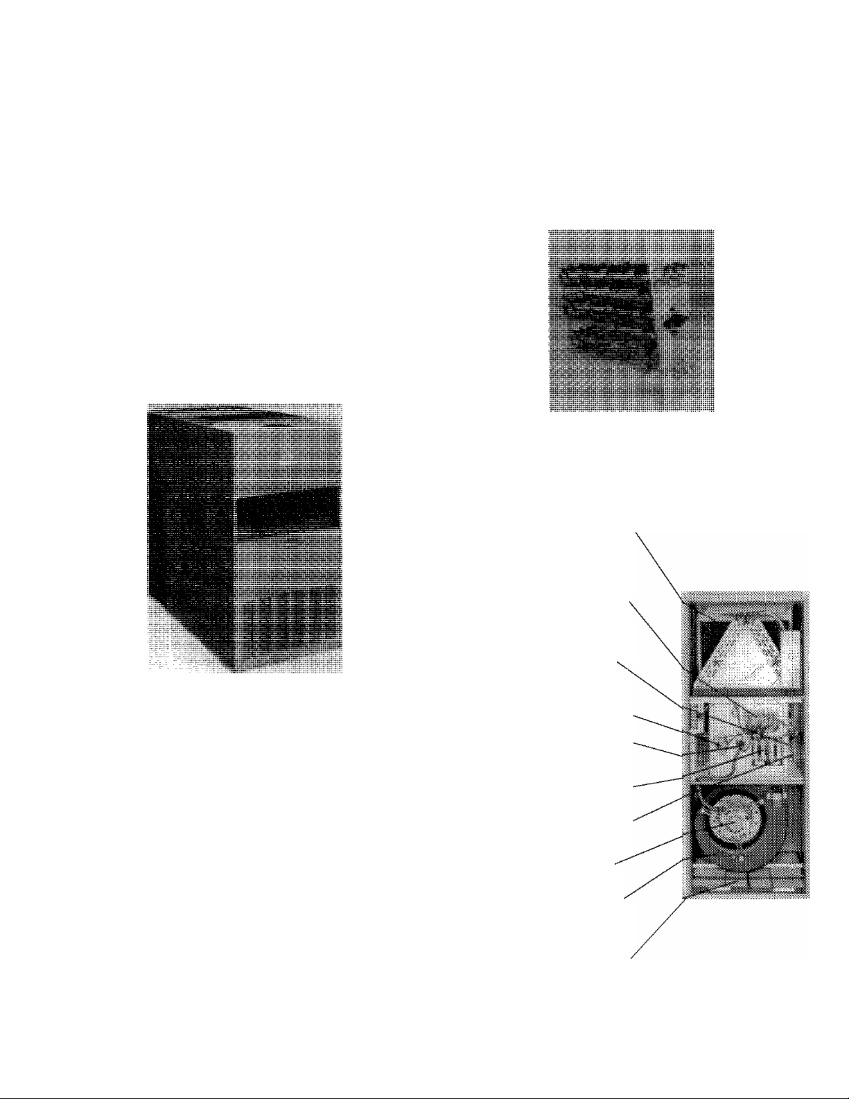
Bard Total Electric Features
Built-In Cooling Coil Compartment—Slidein type for easier conversion to summer cooling,
Accomodates 1-1/2, 2, 2-1/2, and 3 ion
cooling coils.
Controls—On demand from the wall
thermostat, the heating elements are energized
by electrical contactors. The 15 thru 30K.W
versions have the blower motor interlocked with
each stage for safety. Easily two staged.
Limit Switch—Thermal snap disc in each
heating element shuts oif power automatically
if system air temperature becomes excessive
Built-In Transformer—Provides power
supply for heating and optional cooling controls
Blower Relay—Provides automatic blower
speed change-over to meet heating and cooling
air delivery requirements.
Branch Circuit Fusing—Factory installed in
models rated over 48 amps.
Heating Elements—Nickel-chrome wire with
individual fusible links for long life. Entire
assembly slides out for easy maintenance.
Motor—Multi-speed for both heating and
cooling.
Blower—Heated air is quietly circulated by
large volume centrifugal blower that is matched
to the electrical heating system for efficiency.
Slides out for easy maintenance.
Fillers—Twin permanent type slide out from
front for easy cleaning on all models except
Models EFC5 andEFClO.
Page 4
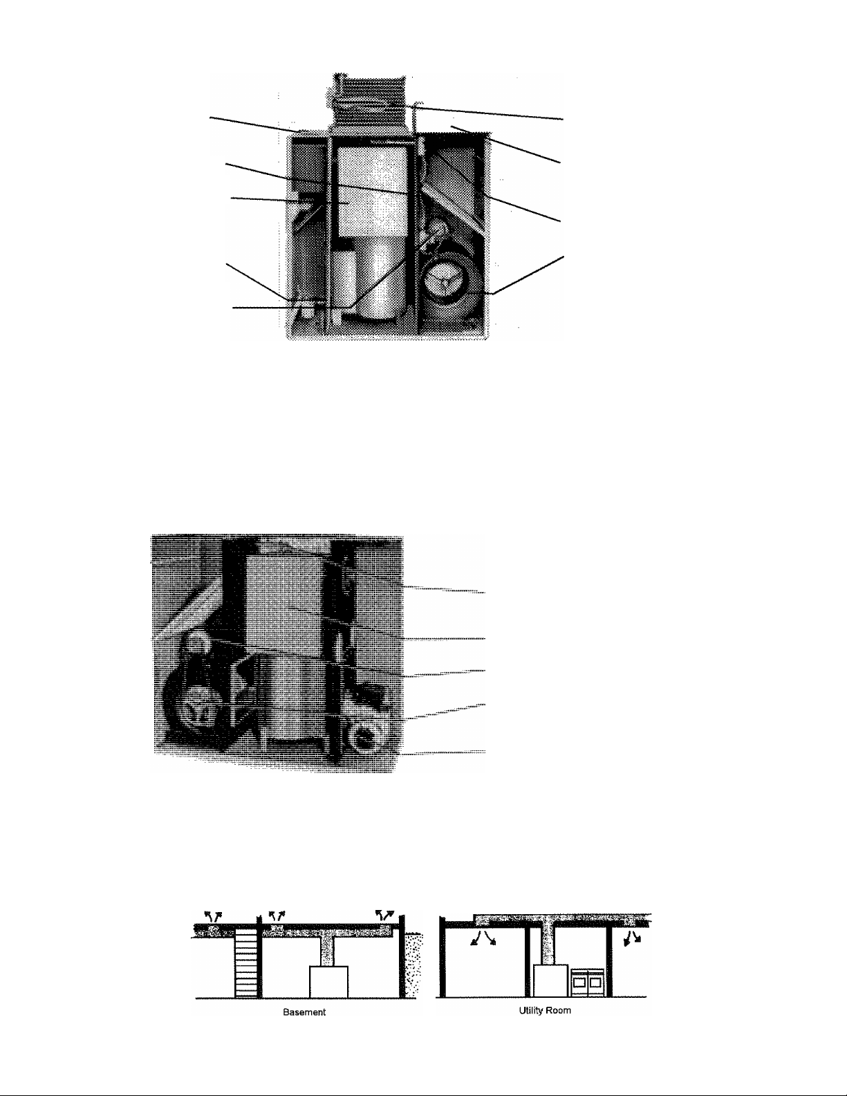
Typical Gas Furnace
Sled Cabinet is accoustically and ihennaUy
insulated for quieter operation and minimum
heat loss.
Filter is extra large for better system air cleaning
efficiency.
Heat Exchanger efficiently extracts all usable —
heat for greater fuel economy.
Safety Pilot provides 100% automatic shut-o£f
for safely.
Mono“.Jet® Burner provides ease in adjustment
and has uniform flame distribution for maximum
efficiency.
Powerful Blower Motor is resilient mounted for
quieter operation.
Model G152
All components are easily accessible for service and inspection.
Typical Oil Furnace
Bard Cooling Coils with plenum and system matched
components are optional for converting to summer
air conditionirrg.
Electrostatic Air Cleaner traps up to 95% of air-bome
dust, bacteria-size particles, smoke, odors and 99%
pollen. This optional accessory may be installed with
furnace or added later.
Fan and Limit Control with helcx element
automatically controls blower and burner operation.
Blower is capaci^ matched to heating components and
quietly circulates air throughout system.
Typical Installations
steel Cabinet is accoustically and ihermaOy
insulated for quieter operation and minimum heat
loss.
Fan and Limit Control with helex element
automatically controls blower and burner
operation.
Heat Exchanger provides more heating surface
for efficiency.
Motor has resilient base mounting for both
heating or cooling applications.
Blower is centrifugal type, dynamically balanced
and mounted on rubber grommets for quieter
operation.
Burner is designed for super-quiet efficiency.
Page 5
Cooling Section
This cooling section in a typical split-system application is the
indoor evaporator coil. This coil is located in the supply plenum of
the furnace. Stated simply, cool refrigerant is pumped through the
evaporator coil by the cooling unit. The refrigerant in the
evaporator coil removes heat from the air, and the furnace blower
distributes this cool air to the conditioned spaces.
Blower
The device which moves the treated air to points throughout the
home is called the blower, The blower consists of a wheel with air
scoops sometimes called a scroll and a motor to drive the wheel.
There are two types of blowers; a belt drive and a direct drive.
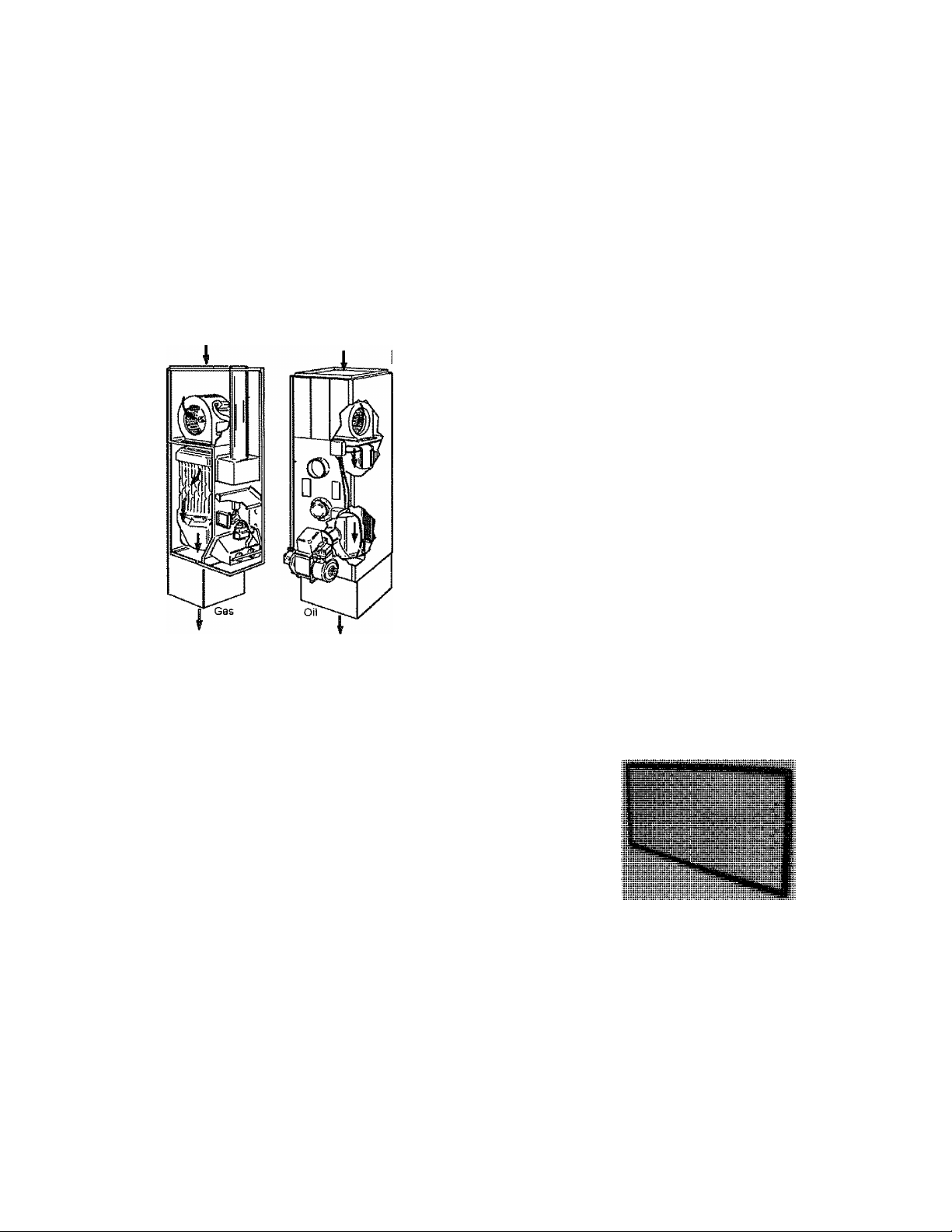
Illustrated here are typical gas-fired and oil-burning
counterllow furnaces.
Belt Drive Blower
A belt runs from a pulley mounted on the motor to a pulley
mounted on the blower wheel, All moving parts are anchored on a
rigid U-ffame, which in turn is fastened on resilient mountings to
the furnace. The design of this frame insures easy adjustment and
alignment of pulleys and belts for optimum performance. Varying
amounts of air can be moved by a belt drive blower, depending
upon the motor pulley size adjustment (see diagram). The pulley
can be made larger by screwing one side of the pulley inward
toward the other side; this causes the blower wheel to rotate faster.
Screwing one side outward from the other side reduces the pulley's
effective circumference, which in turn reduces the speed of the
blower wheel. If volumes of air are desired, which caimot be
obtained by motor pulley adjustment, the motor or blower pulleys
themselves can be changed,
NOTE: A larger pulley might also necessitate a larger motor.
Direct Drive Blower
The direct drive blower motor is mounted inside the blower and is
directly linked to the blower wheel. Air volume changes are made
by electrically varying the speed of the motor. The speed in direct
drive blowers is changed depending upon which of several wire
leads (speed taps) coming from the motor are used. Usually two to
five speeds can be obtained by wiring the hot wire to the desired
speed tap lead and the neutral wire to the common motor lead. The
unused hot wire leads must be taped separately to prevent coming
in contact with an electrical ground. The rotating motor produces a
back voltage (emO of approximately 200 vac through
electromagnetic induction.
WARNING
A
Use caution when handling these leads with 200 vac
electrical potential. If not taped, they could cause arcing
to ground, shorts or serious electrical shocks.
Filter
A filter is the device in a forced air heating or cooling unit which
mechanically screens out dust, dirt, lint and other impurities from
the Systran's airstream.
The filter is usually located just upstream from the blower, in the
return air side of the system. A fiberglass media commonly acts as
the screen, cleaning the air before it is recirculated throughout the
system by the blower.
A dirty filter greatly reduces the system's airflow, which greatly
reduces the operating efficiency of the heating or cooling unit. For
this reason, The homeowner should be instructed to check the filter
monthly and clean or replace it if necessary. (Never reuse a dirty
filter by turning it bottomside up; this will result in the collected
dirt being dumped back into the airstream.)
Two types of filters are the disposable and the permanent. Most
slab filters are disposable, consisting of rectangular fiberglass
screen in a cardboard frame. These come in a variety of sizes to fit
completely across the airstream. Arrows marked on the frame
indicate correct placement with respect to system airflow. When
the filter becomes dirty, it should simply be removed and a new one
put in its place. A nondisposable slab filter uses a polyurethane
media encased in a metal frame. When this filter becomes dirty, the
media may be cleaned (washed or vacuumed) and reused.
Thermostat
The thermostat is a heat sensitive switch that serves as the
automatic control center for heating and cooling system operation.
Since the thermostat was discussed in detail in a previous manual,
its story will not be repeated here. The student should review the
manual on thermostats if necessary.
Page 6

Electrical System Components
Furnace Circuits
All circuits within the oil firmaces are designed and wired in
accordance with Underwriters Laboratories’ requirements. They
have been inspected and tested at the factory to qualify for the UL
label which is attached to the furnace.
All circuits within the gas firmace are designed and wired in
accordance with American Gas Association requirements. They
have been inspected and tested at the factory to qualify for the
AGA Label which is attached to the furnace.
Black
White
Fused switch box
All switching within the furnace line voltage circuits is done in the
hot 120V leg. The reason is that switching, if done in the ground
leg, could result in an unsafe grounding fault. See diagram.
Switch open, furnace
does not run, fuse blows_
when switch closes
Short to
ground
X
To
Gi|(-
Switch in hot leg
Right
Wrong
Switch in ground leg
furnace.
connected electrically. These variations and the reasons for each are
discussed in Manual 2100-058, “Basic Electricity.”
The type and size of blower motor installed in a fiimace depends
upon flie blower load required to deliver the correct amount of air to
the heating system. Because the heating system varies from one
installation to another, the blower speed needs to be adjustable to
match the needs of the air distribution system. This speed
adjustment may be done either mechanically or electrically.
The motor may be connected to the blower by a belt and pulley. In
this case, the speed adjustment is accomplished mechanically by a
change in the pulleys. This is referred to as a “belt-drive blower.”
Or the blower wheel may be mounted directly on the motor shaft.
In this case, the motor speed must be changed electrically. This is
referred to as a “direct-drive blower,”
To
G.||-
Switch open
furnace runs
fuse does not blow
furnace
ground
The first load in all forced warm air systems is the blower motor
which is always line voltage. Therefore, the fiimace blower motor
is the first electrical component wired into the system.
Now when the disconnect switch lever is closed to the “on”
position, this will make a complete circuit and energize the
blower motor. This motor, in turn, drives the blower which
delivers the air through the furnace and duct system. When
the lever is placed in the “off” position, the circuit is not complete
and the blower motor will not run. Airflow in the system will stop.
The fuse in the switch is placed there to monitor the amount of
current flow in the circuit. If there should be excessive current
flowing in the circuit, the fuse will bum out and open the circuit.
Blower Motors
At this point, the blower motor has been wired into the circuit. This
is the basic circuit shown in the wiring diagrams. However, there
are variations in the blower motors used and the way they are
Fan Control Switch
One of the major controls in the line voltage circuit will be the fan
control. The fan control switch is a heat-actuated switch which is
equipped with normally open contacts. It contains a bi-metal type
of heat sensing probe which senses the temperature of the air
passing from the furnace into the system.
The furnace illustration shows the location of the fan control in an
upflow type fiimace. The probe is usually a “spiral” type and is
installed into the heating unit on the front side of the cabinet with
the bimetal probe inserted through the cabinet into the heat
exchanger portion of the furnace. Its position must be such that the
bimetal probe can sense the temperature of the air passing from the
Page 7

heat exchanger. When this temperature reaches a predetermined
point, the bi-metal closes the normally open contacts thus making a
complete circuit, starting the blower motor.
Internal view of L4064, showing use of screwdriver to connect
to disconnect wires at push-in terminals, NOTE: Because the
dial turns when the eiement temperature changes, the lettering
on the dial may not be horizontal
There are basically two types of fan controls. One is called a
combination control. See illustration. The fan control portion is
provided with two adjustable levers—one to set the blower
“on” temperature and the other to set the blower “off” temperature.
The “break” or “off” point on the switch can be field set and
should usually be set about 25“ below the make point. If the switch
is set well below return air or room temperature during the normal
heating season, continuous blower operation would be
accomplished.
The difference between the fan "on” and “off” points is called the
fan control differential. The temperature difference between these
two points may be set from 15 to 25“. If the differential is set too
low, the control will cycle because of slight temperature
fluctuations. This causes undesirable fan cycling. If set at more
than 25“, the blower would have to wait too long before coming
“on” increasing the heat loss fi'om the furnace and reducing the
furnace efficiency.
The other type is the single fan control. It has just one adjustable
lever by which the desired blower “off” temperature is set. This is
a fixed differential control with a built-in differential of 25“ F,
Therefore, the blower “on” temperature will always be 25“ F higher
than the blower “off” dial setting.
Note that if the homeowner desires to have continuous air
circulation (CAC), it will be necessary to set the open or
break point below the normal return air temperature. In this
way, the air passing over the heat exchanger will remain above the
setting even though the burners are off and the blower will continue
to run.
Fan contro! switch*
upfiow, highboy furnaces.
The settings of the fan control are normally field adjusted according
to the desires of the homeowner and the “on” or “make” point is
usually somewhere around 100“. This means that when the air
passing over the heat exchanger reaches approximately 100“, the
switch will “make” and the fan will come on, delivering air to
the space.
Combination fan and limit control
Fan (on)
25^ Differential setting
Downflow and Horizontal Units
Downflow and horizontal units present a little different problem
than the upflow units. The fan control probe location in a downflow
imit will work fine on the “make” or “on” cycle, because the fan
would not be running and the heat exchanger would rise through
the heat exchanger actuating the probe. However, once the fan is
Page 8

running, the air is flowing in the opposite direction from the probe
and when the burners would go off, the probe would sense the cool
return air rather than the heat in the heat exchanger. This would
fool the probe into thinking that the heat exchanger had cooled
down and could actuate the contacts to their normal position,
cycling the fan off too soon. Once off, it would sense the residual
heat in tlie heat exchanger being transferred to the air around it and
again, actuate the contacts energizing the blower and cycling it
until the heat exchanger has been cooled sufficiently,
The same type of problem would be true for a horizontal type
furnace, since it would not be possible to locate the blower
control in an ideal position for both the “make” and “break”
actions.
Limit Control
A safety device is connected into the line voltage circuit next. It is
called a limit control. The purpose for this “limit” is to turn off the
burner and control circuits if the air temperature becomes too high.
Some limit controls are combined with the fan control. See
photograph. In this case, one bimetal actuates both the fan
control switch and the limit control switch. As the temperature
rises, the bimetal will first turn on the fan switch and start the
blower. If a condition exists which causes overheating, the bimetal
will continue to warp or turn until the limit cutout temperature is
reached and it trips the limit switch.
The limit switch in the combination control is provided with an
adjustable lever. A step is installed which will not allow the lever
to be set above the safe cutout temperature—usually 200° F. The
lever should not be adjusted below this high limit temperature
since it will cause false or nuisance burner cycling.
The limit control prevents overheating of the furnace which could
cause a fire or damage to the fiimace components. It shuts off the
burner if conditions or failure should occur such as blower failure,
dirty air filter, blockage of the duct system or any condition which
abnormally restricts air flow through the fiimace.
The limit control is actuated by a bimetal element in the discharge
air stream. Therefore, it monitors the air temperature leaving the
heat exchanger. The bimetal is linked to a normally closed switch
which has an SPST action. If the air temperature rises to the limit
cutout temperature, the bimetal opens the switch and breaks the
line voltage circuit to the burner and controls.
Limit Control
Pictorial symbol
On most furnaces, the limit control is calibrated to shut off the
burner if the discharge air temperature reaches or exceeds 200° F.
The limit control will automatically recycle (reclose its contacts)
when the temperature drops 25° below the cutout point. Therefore,
the limit control will recycle the burner if the thermostat is calling
for heat, but will not allow the temperature to exceed 200° F.
The limit cutout temperature is factory set and the differential is
built into the switch. Neither should be readjusted or changed in
the field. Otherwise the equipment warranty will be voided and a
hazardous condition will be created.
Another common limit control is illustrated. This limit has its own
bimetal element and is located at a different point on the furnace
than the fan control. It acts the same as the combination limit but
does not have a dial setting. It is a fixed setting and fixed
differential control. Again the setting is usually 200° F and the
differential is 25° F. These are set and sealed by the control
manufacturer.
Upper Limit Control
As was outlined imder the discussion of the fan control, for
downflow and horizontal heating imits, an additional limit
control is used. This upper limit is installed in the blower
outlet or between the blower outlet and the heating section,
or very near the blower section of the imit.
The reason is that the high temperature limit is at the discharge end
of the heat exchanger. Before the blower comes on, the warm air
rises away from this high limit preventing it from sensing the
temperature and providing the protection needed, During this
period, the upper limit provides backup protection by sensing the
heated air that rises upward in the unit by gravity.
This upper limit control provides protection in case of blower
failure or excessive restriction in the system which prevents the
movement of air. Usually the limit cutout temperature is 140° F
with a differential of 25° F.
The switch in the upper limit control is an SPDT action. The
normally closed contacts are located in series ahead of the
high limit contacts in the electrical circuit. Therefore, if either
limit is “open” the burner and control circuits become deenergized.
The upper limit does one other thing. When the limit contacts are
open, the other normally open contacts then close. This completes a
circuit directly to the blower motor starting the blower.
There are several reasons for this feature. One is to put the upper
limit back in step if it should trip open from residual heat after the
fan control has turned the blower off. It simply overrides the fan
control to provide cool air on its own elements. When the limit
contacts reclose the blower contacts open, shutting off the blower.
A second reason is to back up the fan control timer if it should fail
to operate as it should.
Page 9

A third reason is that the upper limit control de-energizes the
control circuit. Under some circumstances, this secondary limit
could be open up to one hour preventing the control circuit from
operating the fan timer or burner circuits. For the thermostat to do
its job and get the furnace back in operation, power must be
provided to the control circuit.
Additive Cooling Relay
NOTE: When cooling is added to a standard furnace, an
additive cooling relay is required.
The line voltage side of this relay has a set of contacts which
bypass the fan control, delivering power directly to the blower
motor. The contacts are pulled in by a low voltage coil which
is energized on a call for cooling from the thermostat or if the
thermostat fan switch is set for constant blower operation. Note
that electrically both the 24 V and 120 V circuits are completely
independent, but one controls the other by pulling in its contacts.
The blower relay is necessary because on cooling, the temperature
of the air being circulated through the system would be below the
set point of the fan control and this would shut off and not allow
the blower to run. Under cooling without the blower running, the
evaporator coil would ice up and the condensing unit would go off
on its limit control.
The transformer must be sized to handle the current (amperage)
requirement of the load or loads connected to the secondary side of
the transformer. The transformer select may be
requirement, but the transformer can never be smaller than the load
requirement (amp-draw). Short circuit protection for the 24V side
of the transformer is provided in some cases by a replaceable fuse
and in others as fusible link. The fusible link is built in and
requires replacement of the entire transformer if it bums out.
larger than the load
Additive
coDling relay
24 Volt or Low Voltage Control Circuit
In almost all residential forced warm air heating systems, the
control circuits are powered with low voltage (24 volts). There
are several reasons for using low voltage: ease of installation, lower
installation cost, closer (better) temperature control and less
possibility of electrical shocks.
Transformer
In order to supply 24 volt power in control circuits, a “step-down”
transformer is used. Tlie line side is wired directly into the 115V
power supply.
Basically a transformer consists of two coils of insulated wire
wound on a common iron core. The coil connected to the line
voltage or input side is the primary coil and the output or load side
is always the secondary. If the voltage on the line side is greater
than that on the load side, it is a “stepdown” transformer. If the
voltage on the load side is greater than the line side, it is a “setup”
transformer. Therefore, to supply 24V on the load side from 115V
line, a stepdown transformer is used.
Transformers are always rated in volt amperes (VA), which is the
amount of electrical power (volts x amps) it can supply.
Thermostat
The first load that will be attached to the low voltage circuit is the
thermostat. Basic operation of the thermostat and its internal
wiring has been discussed in a previous manual, and here the
common leg will be connected to one side of the transformer and
the fan and heating circuits will be connected to the other side of
the transformer. The thermostat can now control the fan circuit
independently from the heating and cooling circuits.
Basic Maintenance Procedures
Regularly scheduled basic maintenance calls are mutually
beneficial to both the service firm and the homeowner/customer.
Normally, this involves two maintenance calls per year—one in the
fall prior to the heating season and one in the spring prior to the
cooling season.
Maintenance Check Sheet
A maintenance check sheet has been developed which has
checklists for residential gas, oil and electric heating units and
cooling systems and accessories. The check sheet had checklists
Page 10

Maintenance Checksheet
Dealer
___
_________________________________________
Customer
Date
Equipment Make & Models
Notes
________
Pre-Service Check
n Customer satisfied with system performance
□ Customer dissatisfied with system performance.
Thermostat Checks
□ Record thermostat settings: Temp.;
Mode: HEAT OFF COOL FAN ON AUTO
□ Check terminal connections for tightness
n Clean bimetal. Inspect mercury switch
n Check thermostat for level
□ Check control circuit amperage;________________
D If customer dissatisfied with temperature control in heating season, adjust
anticipator to match control circuit amp draw
□ Initiate appropriate seasonal demand from thermostat
Blower Compartment Checks
n Check supply voltage at junction box; _
□ Check blower motor amperage;
□ Turn power at unit main disconnect to OFF
n Check alt wiring for loose connections and bad insulation
______
D Clean or change filter
Direct Drive Blower
n Check blower bearings
□ Lubricate blower bearings
□ Clean blower and compartment
□ Check blower wheel for free and balanced rotation
D Check all blower housing mounts and setscrews for tightness
□ Unused motor leads taped and out of way
Beit Drive Blower
n Remove biower belt and check for wear
□ Check motor bearings for wear
□ Lubricate motor bearings
□ Check blower wheel bearings for wear
n Lubricate biower wheel bearings
n Clean blower and compartment
D Check blower wheel for free and balanced rotation
□ Check pulley alignment
□ Check motor and blower pulley setscrews for tightness
D Put belt back on blower and motor pulley and check belt tension
□ Check all biower housing and motor mounts for tightness
Person
_____________
_________
nameplate rating
______
time
Address
Address
____
Time Out
dcmv closed circuit _
_______________
“F
Time In
Standing Pilot
□ Check pilot flame
□ Check thermocouple open circuit
□ Check pilot valve safety drop>aut time _
□ Check automatic vent damper system
□ Check iimit safety
□ Check temperature rise
□ Gas manifold hand valve is open before leaving
_________________
Oil
□ Check electrical wiring — connections and insulation
n Inspect combustion chamber
D inspect for soot in heat exchanger
□ Change fuel oil tank for sludge/watar
□ Change oil line filter
□ Check oil lines
D Service oil burner
□ Conduct combustion efficiency test:
__________
□ Check iimit safety
□ Check temperature rise
D Check primary control
□ Check furnace vent for rust
in.w,c, smoke
_______________
% C02.
Cooling
□ Check electrical wiring — connections and insulation (indoor)
G Check/clean evaporator coil
D Check/clean condensation drain
□ Check static pressure drop
□ Check wiring — connections and insulation (outdoor)
□ Check/clean condenser coil
□ Lubricate condenser fan motor
D Check line set and connections for evidence of leaks
□ Check and record supply voltage
□ Check refrigerant charge
□ Check amperage draw on condenser fan motor
□ Check amperage draw on compressor
___________
in. w.c.
_________
Humidifier
□ Check electrical wiring — connections and insulation
□ Check transformer voltage
□ Check damper position
_____________________
dcmv
min.
°F net
_cfm (dry coil)
Heating Section Checks
Electric
□ Check electrical wiring — connections and insulation
□ Check amperage draw of each element
□ Check total amperage draw of elements
□ Check temperature rise
n Return outdoor thermostats to original settings if present
________________________
___________
Gas
□ Check ail electrical wiring for loose connections and damaged insulation
D Check burners for lint, dust and scale
□ Check for cracks in heat exchanger
G Check furnace vent for size and deterioration
□ Check for quiet, even burner ignition
□ Check supply line gas pressure NAT
D Check manifold gas pressure NAT
Electronic Ignition Control
□ Check electronic ignition control sequence of operation
D Check safety lockout
n Check pressure switch
____________________
_____________________
________
________
in. w.c, LP____________in. w.c.
in. w.c. LP
min.
____________
amps
F
in. w.c.
Spray Type
□ Check solenoid valve
□ Check nozzle spray pattern
Drum Type
□ Check for free rotation and scale
□ Check wafer level adjustment
□ Check overflow/drain line
Electronic Air Cleaner
□ Check electrical wiring — connections and insulation
G Check sail switch or electrical biower interlock
□ Cheekiest button operation
□ Check supply voltage
□ Check voltage to collecting ptates
□ Check voltage to ionization wires_
GTURN power OFF
D Wash cells
□ Wash prefilter screens
_________________________
_ vac (120 vac)
vdc (3500 vdc)
^ vdc (8000 vdc)
Post-Service Checks
G Return thermostat to original settings recorded at beginning of service call
G Leave copy of completed checksheef wHh customer
□ Power ON before leaving
FI 385-895
Page 11

which itemize the basic maintenance steps and assist in organizing
the service tasks to be performed.
It is suggested the service person attach the check sheet to a
clipboard and cany it to the service call. Filing in the checklists
while proceeding with the call will ensure that all the necessary
checks are performed efficiently. The check sheet should be
completed in duplicate. One copy is for the customer. The check
sheet folder copy is for the firm’s reference file.
The check sheet also has other potential uses. For example, listing
the make and model of the equipment gives the firm quick
reference for service and parts information. And by analyzing “time
in and out”, the firm can accumulate labor cost data on its planned
service operation. It is a valuable sales tool for add-on and
replacement and accessory business. Service personnel should
always keep this important aspect in mind. Tips that generate sales
will help you and your company grow. The maintenance sheet is a
convenient means to document this information.
The checks corrunon to all heating and cooling units, namely those
at the thermostat, blower and filter, will now be covered.
□ Check terminal connections for tightness.
1, Remove thermostat cover,
2, Tighten terminal connections if necessary.
□ Clean bimetal.
1. Carefully remove dust and dirt from bimetal with soft brush
or by blowing on it.
2. Inspect the mercury switch for cracks in the glass bulb and
brush away any accumulated dust. If mercury switch is
damaged, discuss problem with homeowner and notify
sales manager.
□ Check thermostat for level.
1. Place level on thermostat and adjust thermostat position if
not perfectly level. A level thermostat is a necessity for
precise temperature control.
□ Check control circuit amperage_
1. Single-stage heating or cooling thermostat. Connect one clip
of 10 loop amperage multiplier to “power from transformer”
thermostat terminal; coimect other multiplier clip to
“heating” thermostat terminal if checking heating system or
“cooling” terminal if checking cooling system; snap amprobe
just around multiplier coil and record actual amperage draw
(move decimal point of amprobe reading one place to the left
to obtain actual amp draw, i.e. 4.5 reading ~ .45 actual amp
draw).
_amps.
Pre-Service Check
□ Customer satisfied with system performance.
□ Customer dissatisfied with system performance.
1. The planned service appointment should be scheduled in
advance so that arrangements can be made to gain access to
the comfort equipment.
2. Prior to beginning the maintenance checks, the service person
should ask the customer how the system is performing. This
will help get a reading on current system operation and
pinpoint possible problems to investigate and correct.
3. If the customer indicates satisfaction with the system
operation, the service person can concentrate on the routine
maintenance checks.
Thermostat
Record thermostat settings:
Temp
__________
□ Cool Fan switch:
1. Recording these settings will enable service personnel to
reset thermostat to customer’s desires at end of service call.
2, Some electric units may also employ an outdoor thermostat
for multiple staging of heat elements (see Electric Heat
Section). Record outdoor thermostat setting.
°F Mode:
□ Heat □ Off
□ On □ Auto
2. With two-stage heating thermostat. Check first stage circuit
amperage using method outlined above for single thermostat.
To check second stage circuit amperage, attach one jumper
wire clip to power terminal and other clip to “first stage heat”
terminals; attach one amperage multiplier clip to “power”
terminal; connect other multiplier clip to the “second stage
heating” thermostat terminal; record actual amperage draw
(by adjusting reading one decimal to tlie left).
□ If customer is dissatisfied with temperature control in heating
season, adjust heat anticipator setting to match control circuit
amp draw reading.
1. If customer is satisfied with temperature control, do not
adjust anticipator and proceed with next service check.
2, If during the heating season the customer complains of being
too hot even after the furnace has cycled off, the heat
anticipator setting should be adjusted to shorten the fiomace’s
“on” cycle; if the customer is too cool, the anticipator should
be adjusted to lengthen the “on” cycle. The cooling
anticipator is usually nonadjuslable. Review the thermostat
manual details on anticipator adjustment.
Page 12

□ initiate appropriate seasonal demand from the thermostat
with fan switch on auto; □ Heat □ Cool
1. if making heating unit checks, demand is created by turning
thermostat to highest setting with mode switch on heat.
2. if making cooling system checks, demand is created by
turning thermostat to lowest setting with mode switch on
coo!.
3. if the electric frimace employs an outdoor thermostat for
staging of heat elements, set the dial at its highest setting to
initiate a multiple stage demand. Return dial to original set
points before leaving the site.
Blower Compartment Check
□ Check supply voltage at unit junction box.
__________
1, Remove access doors on front of unit,
2, Set volt-ohm meter above 120 vac,
3, Attach volt-ohm meter probes to incoming line voltage and
neutral wires in junction box.
□ Check blower motor amperate^
1. Snap amprobe around neutral or common wire leading to the
blower motor.
vac
_______________
_^Nameplate A rating
time
A.
3. Compare amp reading with amp rating on motor nameplate.
An excessive amp draw reading is a clue the motor is
working too hard. Possible causes:
Extremely dirty motor prevents air from dissipating heat
and motor runs hot. Seized or worn bearings cause excess
pull or drag; motor (and/or pulley on belt drive blowers)
improperly sized in relation to blower wheel. Poorly
designed system application.
if following service checks do not alleviate high
motor amperage, refer problem to residential equipment
troubleshooter or service manager.
4, Remove blower compartment door.
□ Turn power at unit main disconnect to off.
□ Check all wiring for loose connections and bad insulation.
I, Tighten loose connections. Wrap electrical tape around wires
with cracked or worn insulation.
□ Clean or change filter.
NOTE: See unit installation instructions for removing filters from
downflow furnaces.
Nondisposable Slab (Polyurethane)
1. Remove filter from unit.
2. Remove media from frame.
3. Wash or vacuum media.
4. If media is washed, use hot water and detergent,
5. Squeeze water from media, put in frame and coat side of
media opposite the blower with a filter spray (the oil spray
enhances collection of dirt particles).
6. Place filter back into unit.
Disposable Slab (Fiberglass/Cardboard)
1. Remove filter from unit.
2. Wrap in newspaper and discard.
3. Place new filter of same size in unit. Make sure filter is
placed so that arrows on filter frame agree with system
airflow, if applicable.
Direct Drive Blower
WARNING
A
Be sure power to furnace is off.
2, In order to stimulate the tme operating condition, put blower
compartment door in place. Leave a small opening to allow
for reading the amprobe.
10
Page 13

Cutoff plate
1. Spin wheel. If wheel is badly out of balance or hits against
housing, blower should be replaced. Notify service manager.
2. If dislodged balance weights are found, place them in exact
location they formerly occupied. Look for scratches on blades
to show where weight clip was attached.
When wheel is spun, the heavier side will fall to bottom. This
means the side minus the weight is probably on top. If the
old location cannot be found, leave weights off rather than
risk further imbalance by inconect placement,
Direct drive biovrer showing cutoff piate
□ Check blower motor bearings.
1. Grasp blower wheel and move in back and forth and up and
down directions.
2. There should be no more than 1/8 inch back and forth
movement. There should not be any up and down movement,
3. if there is movement, bearings are wearing. Service person
should inform customer of bearing condition. If problem is
severe, blower motor should be replaced. Notify service
manager.
□ Lubricate blower motor bearings.
1. Check motor for service instructions and lubrication instructions
in xmit installation instruction manual,
2. Prelubricated motor bearings with oil ports require a few drops
of SAE No. 10 nondetergent oil every two years.
A
□ Clean blower compartment.
A
NOTE: It is necessary to remove cutoff plate when removing
□ Check blower wheel for free and balanced rotation.
CAUTION
Do not over lubricate motor bearings. Excessive oil
attracts dust and dirt.
CAUTION
Do not dislodge balanee weights attached to blower
wheel blades.
Balance weight clip
1. Remove dust and dirt for air scoops or vanes of blower
wheel. This may be done with moist rag or vacuum.
2. if blower is exeessively dirty, it should be removed from unit
and thoroughly washed/eleaned using high pressure hose.
Remove motor from blower assembly when washing blower.
Make sure motor is completely dry before it is put back
into operation.
motor. Be sure to replaee plate before replacing
motor to ensure proper airflow.
3. If blower was removed for cleaning, reinstall at this time.
□ Check all blower housing mounts and setscrews for tightness.
□ Check that unused motor leads are taped and out of the way.
Belt Drive Motor
WARNING
A
Be sure power to hamace is off.
□ Remove belt and check for wear.
1. Loosen motor mount and push motor toward blower wheel.
2. Remove belt by sliding it off the pulleys,
3. Check for wear by turning belt inside out and looking for
splits and cracks in the rubber.
4. Replace belt if there are signs of wear. (Leave belt off to
perform the following checks. You will be instructed when to
put it back on.)
□ Check motor bearings for wear.
1. Grasp motor pulley,
2. Push pulley in inward and outward directions. Assuming the
pulley is mounted tightly to the motor shaft or drive, there
should be no more than 1/8 inch movement or play in
either direction.
3. Move pulley in up and down directions. There should be no
movement in either direction.
4. If there is movement in motor shaft, bearings are wearing.
Service person should inform eustomer of bearing condition.
If problem is severe, motor should be replaced. Notify
serviee manager.
□ Lubricate motor bearings.
1. Check motor for service instructions and lubrication
instruction in unit installation manual.
2. Prelubricated bearings require a few drops of SAE No. 10
nondetergent oil every two years.
CAUTION
A
Do not over lubricate motor bearings. Excessive
lubrieation attracts dirt and dust. Oil splash on the belt
eauses shortened belt life.
11
Page 14

3. Motor bearings with oil cups or holes. Add a few drops of
automotive 10 nondetergent oil.
□ Check blower wheel bearings for wear.
1. Grasp blower pulley and move in up and down directions.
Also push in and out. There should be no movement in any
direction if the pulley is mounted tightly to the blower shaft.
2. Grasp shaft and test bearings on opposite side of blower
wheel. There should be no movement.
3. If there is in and out movement on either side, move locking
collars on the affected side closer to bearing as follows:
On the pulley side, loosen set screw on shaft and
remove pulley.
Loosen collar set screw and move collar snugly against
bearing housing. Tighten collar setscrew.
2. If grooves of pulleys do not line up, loosen shaft setscrew and
move motor pulley until it is aligned with blower pulley,
3. Tighten motor pulley setscrew and recheck alignment.
□ Check motor and blower pulley setscrews for tightness.
An adjustable motor pulley has two setscrews, one to tighten
the adjustable pulley sheave and one to tighten the pulley to
the motor shaft.
Set screw to tighten
pulley on motor shaft
Set screw to tighten
adjustable sheave
4. If there is still movement, bearings are worn. Inform
customer of bearing condition. If problem is severe, blower
bearings should be replaced. Notify service manager.
□ Lubricate blower wheel bearings.
1. Bearings with no lubricant fittings. These are permanently
sealed and lubricated and require no service.
2. Bearings with grease cups, Turn grease cup down
approximately one turn yearly. When cups are turned to the
bottom, refill with lubricant.
Bearings with grease plugs. These are normally prelubricated
and require lubrication about every two years. If lubricant is
required, use No. 2 neutral mineral grease. Check lubrication
instruction.
□ Clean blower and compartment.
1. Remove dirt from air scoops or vanes of blower wheel. This
may be done with moist rag or vacuum.
2. If blower is excessively dirty, it should be removed and
thoroughly washed/cleaned using high pressure hose.
Remove motor from blower assembly before washing blower.
Make sure motor is completely dry before it is put back into
operation.
□ Check blower wheel for free and balanced rotation.
1. Spin wheel. If wheel is badly out of balance or hits against
housing, blower should be replaced.
2. If dislodged balance weights are found, place them in exact
location they formerly occupied. Look for scratches on blades
to show where weight clip was attached.
□ Put belt back on blower and motor pulleys and check
belt tension.
1. Place belt around pulleys.
2. Adjust motor mount to tighten belt.
3. Check tension by pushing down on belt halfway between
pulleys. Belt should move or deflect from 3/4" to 1".
4. When proper tension is obtained, tighten adjustable motor
mount.
□ Check all blower housing and motor mounts for tightness.
Post-Service Checks
□ Return theimostat(s) to original setting(s) recorded at beginning
of service call,
□ Leave copy of completed check sheet with customer.
□ Power on before leaving.
1. Be sure unit disconnect has been turned on before leaving to
avoid a needless, time consuming callback.
□ Leave all service areas neat and clean.
When wheel is spun, the heavier side will fall to bottom, This
means the side minus the weight is probably on top. If old
location cannot be found, leave weights off rather than risk
further imbalance by incorrect placement,
3. If blower was removed from unit for cleaning, reinstall at
this time.
□ Check pulley alignment,
1, Cheek alignment by placing a straight rod across grooves of
the motor and blower pulleys.
12
Heat Section Checks
These are discussed individually, according to type of fuel used, in
the next sections.
Page 15

1. CoH
2. Flue connection
3. Cabinet
4. Heat exchanger
5. Gas valves & controls
6. Gas burner & manifold
7. Blower
8. Electronic air cleaner
With properly designed systems, add-on equipment and
components will increase the degree of comfort produced
for the homeowner.
Coil
Illustrated here are typical gas-fired and oil-burning horizontal furnaces.
13
 Loading...