

Page 1
UDM
ENABLING BRIGHT OUTCOMES
User manual
Page 2

Product revision
Software Revision: 1.11.x
Barco NV
Beneluxpark 21, 8500 Kortrijk, Belgium
www.barco.com/en/support
www.barco.com
Registered office: Barco NV
President Kennedypark 35, 8500 Kortrijk, Belgium
www.barco.com/en/support
www.barco.com
Page 3

Copyright ©
All rights reserved. No part of this document may be copied, reproduced or translated. It shall not otherwise be
recorded, transmitted or stored in a retrieval system without the prior written consent of Barco.
Changes
Barco provides this manual 'as is' without warranty of any kind, either expressed or implied, including but not
limited to the implied warranties or merchantability and fitness for a particular purpose. Barco may make
improvements and/or changes to the product(s) and/or the program(s) described in this publication at any time
without notice.
This publication could contain technical inaccuracies or typographical errors. Changes are periodically made
to the information in this publication; these changes are incorporated in new editions of this publication.
The latest edition of Barco manuals can be downloaded from the Barco web site www.barco.com or from the
secured Barco web site https://www.barco.com/en/signin.
Trademarks
Brand and product names mentioned in this manual may be trademarks, registered trademarks or copyrights
of their respective holders. All brand and product names mentioned in this manual serve as comments or
examples and are not to be understood as advertising for the products or their manufacturers.
Product Security Incident Response
As a global technology leader, Barco is committed to deliver secure solutions and services to our customers,
while protecting Barco’s intellectual property. When product security concerns are received, the product
security incident response process will be triggered immediately. To address specific security concerns or to
report security issues with Barco products, please inform us via contact details mentioned on
https://www.barco.com/psirt. To protect our customers, Barco does not publically disclose or confirm security
vulnerabilities until Barco has conducted an analysis of the product and issued fixes and/or mitigations.
Patent protection
Please refer to www.barco.com/about-barco/legal/patents
Guarantee and Compensation
Barco provides a guarantee relating to perfect manufacturing as part of the legally stipulated terms of
guarantee. On receipt, the purchaser must immediately inspect all delivered goods for damage incurred during
transport, as well as for material and manufacturing faults Barco must be informed immediately in writing of
any complaints.
The period of guarantee begins on the date of transfer of risks, in the case of special systems and software on
the date of commissioning, at latest 30 days after the transfer of risks. In the event of justified notice of
complaint, Barco can repair the fault or provide a replacement at its own discretion within an appropriate
period. If this measure proves to be impossible or unsuccessful, the purchaser can demand a reduction in the
purchase price or cancellation of the contract. All other claims, in particular those relating to compensation for
direct or indirect damage, and also damage attributed to the operation of software as well as to other services
provided by Barco, being a component of the system or independent service, will be deemed invalid provided
the damage is not proven to be attributed to the absence of properties guaranteed in writing or due to the
intent or gross negligence or part of Barco.
If the purchaser or a third party carries out modifications or repairs on goods delivered by Barco, or if the
goods are handled incorrectly, in particular if the systems are operated incorrectly or if, after the transfer of
risks, the goods are subject to influences not agreed upon in the contract, all guarantee claims of the
purchaser will be rendered invalid. Not included in the guarantee coverage are system failures which are
attributed to programs or special electronic circuitry provided by the purchaser, e. g. interfaces. Normal wear
as well as normal maintenance are not subject to the guarantee provided by Barco either.
The environmental conditions as well as the servicing and maintenance regulations specified in this manual
must be complied with by the customer.
Federal Communications Commission (FCC Statement)
This equipment has been tested and found to comply with the limits for a class A digital device, pursuant to
Part 15 of the FCC rules. These limits are designed to provide reasonable protection against harmful
Page 4

interference when the equipment is operated in a commercial environment. This equipment generates, uses,
and can radiate radio frequency energy and, if not installed and used in accordance with the instruction
manual, may cause harmful interference to radio communications. Operation of this equipment in a residential
area may cause harmful interference, in which case the user will be responsible for correcting any interference
at his own expense
Changes or modifications not expressly approved by the party responsible for compliance could void the
user's authority to operate the equipment
FCC responsible: Barco Inc.
3059 Premiere Parkway Suite 400
30097 Duluth GA, United States
Tel: +1 678 475 8000
EMC notices
EN55032/CISPR32 Class A MME (MultiMedia Equipment)
Warning : This equipment is compliant with Class A of CISPR 32. In a residential environment this equipment
may cause radio interference.
GB/T 9254 Class A ITE (Information Technology Equipment)
Warning : This is a class A product. In a domestic environment this product may cause radio interference in
which case the user may be required to take adequate measures.
BSMI Taiwan Class A statement:
警告使用者 : 此為甲類資訊技術設備,於居住環境中使用 ,可能會造成射頻擾動,在此情況下,使用者會被要
求採取某些適當的對策。
BSMI Reporting Obligor Information / 報驗義務人資訊
一、
二、
三、
商品在國內產製時,為商品之產製者或輸出者。
但商品委託他人產製,並以在國內有住所或營業所之委託者名義,於國內銷售或輸出時,為委託者。
商品在國外產製時,為商品之輸入者。
但商品委託他人輸入,並以在國內有住所或營業所之委託者名義,於國內銷售時,為委託者。
商品之產製者、輸出入者、委託產製或委託輸出入者不明或無法追查時,為銷售者。
前項所稱產製者,包括具有下列情形之一者:
一、組裝者:商品由個別零組件以組裝銷售。
二、修改者:符合檢驗規定之商品於進入市場前,為銷售目的而修改。
Disclaimer for camera usage
Barco provides a kit with a laser range finder and USB camera to help measure the distance from the front of
the projector to the projected surface and monitor the projector its performance. Barco disclaims any liability
for any use of the USB camera outside this intended use.
Disclaimer for network usage
Barco highly recommends to install the projector in a closed network environment to minimize the risk of
leaking, hacking or corrupting of personal and company confidential sensitive information; commercial
sensitive information and/or personal data. Furthermore, strengthen your network security to protect the
projector against unauthorized access by a malicious third parties. To the maximum extent permitted by law,
Barco disclaims any liability for the use of the projector in an open network environment.
Page 5

Table of contents
1 Safety information.................................................................................................................................................................................... 9
1.1 General Considerations ..............................................................................................................................................................10
1.2 Important safety instructions..................................................................................................................................................... 11
1.3 Product safety labels.....................................................................................................................................................................15
1.4 High Brightness precautions: Hazard Distance .............................................................................................................16
1.5 HD for fully enclosed projection systems...........................................................................................................................19
1.6 HD in function of modifying optics .........................................................................................................................................20
1.7 Radio equipment (optional) .......................................................................................................................................................20
2 Getting Started.........................................................................................................................................................................................23
2.1 Getting to know the projector ...................................................................................................................................................24
2.2 Power on the projector.................................................................................................................................................................26
2.3 Start image projection .................................................................................................................................................................. 27
2.4 Switching to standby .....................................................................................................................................................................29
2.5 Power off projector .........................................................................................................................................................................29
3 Pulse Remote Control Unit...........................................................................................................................................................31
3.1 Remote control, battery installation ...................................................................................................................................... 32
3.2 Remote control, protocol setup ...............................................................................................................................................33
3.3 Remote control, on/off button...................................................................................................................................................33
3.4 Using the RCU..................................................................................................................................................................................34
3.5 Functionality overview..................................................................................................................................................................35
3.6 Functions of the “button pressed indicator”......................................................................................................................35
3.7 Function of the RGB filter button ............................................................................................................................................36
3.8 Displaying and Programming addresses into the RCU.............................................................................................36
3.9 Using the XLR connector of the RCU..................................................................................................................................36
3.10 Using the mini-jack connector of the RCU ........................................................................................................................37
3.11 Silicone protection sleeve for the RCU (optional).........................................................................................................37
4 Input & Communication...................................................................................................................................................................39
4.1 Introduction.........................................................................................................................................................................................40
4.2 Local Keypad and LCD panel ..................................................................................................................................................40
4.3 Communication connections ....................................................................................................................................................41
4.4 LED and Button indication chart .............................................................................................................................................43
4.5 Pulse Quad Combo input Mk II ...............................................................................................................................................44
4.6 Pulse Quad Combo input Mk I.................................................................................................................................................45
R5911443 /02 UDM
5
Page 6

4.7 Pulse Quad DP 1.2 input ............................................................................................................................................................46
4.8 Pulse SFP input ...............................................................................................................................................................................47
5 GUI – Introduction.................................................................................................................................................................................49
5.1 Overview..............................................................................................................................................................................................50
5.2 Navigation ...........................................................................................................................................................................................51
5.3 Test Patterns...................................................................................................................................................................................... 52
6 GUI – Source .............................................................................................................................................................................................55
6.1 Displaying a single source......................................................................................................................................................... 56
6.2 Displaying multiple sources: Stitched layouts.................................................................................................................56
6.3 Connector Settings ........................................................................................................................................................................58
7 GUI – Image................................................................................................................................................................................................61
7.1 Setting image levels manually.................................................................................................................................................62
7.2 Adjusting the sharpness..............................................................................................................................................................63
7.3 Adjusting the gamma correction.............................................................................................................................................64
7.4 Setting the desired Gamma type............................................................................................................................................ 65
7.5 Digital Shift & Zoom.......................................................................................................................................................................66
7.6 P7 Realcolor ...................................................................................................................................................................................... 69
7.7 Setting the output resolution.....................................................................................................................................................71
7.8 Displaying HDR content – Perceptual Quantizer (PQ) ..............................................................................................72
8 GUI – Installation....................................................................................................................................................................................75
8.1 Configuring the lens, optical zoom-focus ..........................................................................................................................76
8.2 Configuring the lens, shift...........................................................................................................................................................76
8.3 Configuring the lens, Mid position .........................................................................................................................................77
8.4 Laser ranging ....................................................................................................................................................................................78
8.5 Manipulating the rigging frame ...............................................................................................................................................79
8.6 Orientation ..........................................................................................................................................................................................80
8.7 Warping ................................................................................................................................................................................................ 81
8.7.1 Warping – On/Off.........................................................................................................................................................81
8.7.2 Warping – Screen Size.............................................................................................................................................82
8.7.3 Warping – 4 corners adjustment.........................................................................................................................83
8.7.4 Warping – Bow..............................................................................................................................................................85
8.7.5 Warping – Warp files .................................................................................................................................................89
8.7.6 Warping – Latency control in a multi projector setup .............................................................................. 91
8.8 Blending & masking .......................................................................................................................................................................93
8.8.1 Blend & Mask ................................................................................................................................................................ 93
8.8.2 Blend Files ......................................................................................................................................................................96
8.8.3 Basic black level adjustment ................................................................................................................................97
8.8.4 Black Level Files..........................................................................................................................................................98
8.8.5 RGB adjustment ..........................................................................................................................................................99
8.9 Laser illumination .........................................................................................................................................................................100
8.10 Scaling modes ...............................................................................................................................................................................101
8.11 3D projection ..................................................................................................................................................................................102
8.11.1 Active Stereo & Passive Stereo .......................................................................................................................102
8.11.2 Setup process 3D projection .............................................................................................................................103
8.11.3 Connection possibilities........................................................................................................................................103
8.11.4 Choosing the desired Display Setup .............................................................................................................104
8.11.5 3D emitter Setup.......................................................................................................................................................105
9 GUI – Profiles ........................................................................................................................................................................................ 107
9.1 Profiles introduction ....................................................................................................................................................................108
R5911443 /02 UDM6
Page 7

9.2 Profiles setup parameters .......................................................................................................................................................108
9.3 Enable Profiles ..............................................................................................................................................................................109
10 GUI – System Settings ..................................................................................................................................................................113
10.1 Communication, LAN setup ....................................................................................................................................................114
10.1.1 Introduction to a Network connection ............................................................................................................114
10.1.2 Wired IP address set up ........................................................................................................................................114
10.1.3 Wireless IP address set up ..................................................................................................................................116
10.2 IR control............................................................................................................................................................................................118
10.2.1 Broadcast address ...................................................................................................................................................118
10.2.2 Projector address......................................................................................................................................................119
10.2.3 IR sensors ....................................................................................................................................................................120
10.3 Setting a custom projector name ........................................................................................................................................121
10.4 DMX..................................................................................................................................................................................................... 122
10.5 Front XLR output voltage control ........................................................................................................................................123
10.6 GSM configuration.......................................................................................................................................................................124
10.7 Themes..............................................................................................................................................................................................125
10.8 Setting the measurement system.......................................................................................................................................125
10.9 Lens features..................................................................................................................................................................................126
10.10 Controlling the backlight of the LCD Display ................................................................................................................127
10.11 Reset...................................................................................................................................................................................................128
10.12 Lens Calibration............................................................................................................................................................................130
10.13 Flex brightness.............................................................................................................................................................................. 131
10.14 Rigging frame Calibration........................................................................................................................................................132
10.15 Electronic Convergence...........................................................................................................................................................133
10.16 Advanced Settings ...................................................................................................................................................................... 134
10.16.1 Advanced Settings – Color .................................................................................................................................134
10.16.2 Advanced Settings – Statistics .........................................................................................................................135
11 GUI – Status menu........................................................................................................................................................................... 137
11.1 Status menu overview ...............................................................................................................................................................138
12 Product maintenance..................................................................................................................................................................... 139
12.1 Software update............................................................................................................................................................................140
12.2 Cleaning the lens .........................................................................................................................................................................141
12.3 Cleaning the exterior of the projector................................................................................................................................142
A Specifications ........................................................................................................................................................................................ 143
A.1 Specifications for UDM 4K22 ................................................................................................................................................144
A.2 Specifications for UDM 4K15 ................................................................................................................................................145
A.3 Specifications for UDM W22..................................................................................................................................................147
A.4 Specifications for UDM W15..................................................................................................................................................149
A.5 Specifications SDI inputs.........................................................................................................................................................150
A.6 Specifications HDMI inputs ....................................................................................................................................................151
A.7 Specifications HDBaseT inputs............................................................................................................................................152
A.8 Specifications DisplayPort 1.2 inputs ............................................................................................................................... 153
A.9 Specifications SFP inputs .......................................................................................................................................................154
B Video timing tables........................................................................................................................................................................... 157
B.1 Overview video timings.............................................................................................................................................................158
B.2 Overview video timings SDI Inputs ....................................................................................................................................159
B.3 Overview video timings HDMI 2.0 inputs........................................................................................................................ 160
B.4 Overview video timings DisplayPort 1.2 inputs ...........................................................................................................162
B.5 Overview video timings HDBaseT inputs .......................................................................................................................164
R5911443 /02 UDM 7
Page 8

C DMX chart................................................................................................................................................................................................. 167
C.1 DMX chart input board positioning .....................................................................................................................................168
C.2 DMX chart, Basic ......................................................................................................................................................................... 168
C.3 DMX chart, Extended................................................................................................................................................................. 169
D WiFi & GSM compliance information ............................................................................................................................. 173
D.1 Compliance FCC ..........................................................................................................................................................................174
D.2 Compliance IC ...............................................................................................................................................................................174
E Environmental information........................................................................................................................................................ 177
E.1 Disposal information...................................................................................................................................................................178
E.2 Turkey RoHS compliance........................................................................................................................................................178
E.3 China RoHS compliance.......................................................................................................................................................... 178
E.4 Taiwan RoHS compliance .......................................................................................................................................................180
E.5 Contact information.....................................................................................................................................................................181
E.6 Production address.....................................................................................................................................................................181
Glossary ..................................................................................................................................................................................................... 183
Index .............................................................................................................................................................................................................. 185
List of tools............................................................................................................................................................................................... 189
R5911443 /02 UDM8
Page 9

Safety information 1
1.1 General Considerations ................................................................................................................ 10
1.2 Important safety instructions .......................................................................................................... 11
1.3 Product safety labels..................................................................................................................... 15
1.4 High Brightness precautions: Hazard Distance................................................................................ 16
1.5 HD for fully enclosed projection systems......................................................................................... 19
1.6 HD in function of modifying optics ..................................................................................................20
1.7 Radio equipment (optional) ........................................................................................................... 20
About this document
Read this document attentively. It contains important information to prevent personal injury while installing and
using the UDM projector. Furthermore, it includes several cautions to prevent damage to the UDM projector.
Ensure that you understand and follow all safety guidelines, safety instructions and warnings mentioned in this
chapter before installing the UDM projector.
Clarification of the term “UDM” used in this document
When referring in this document to the term “UDM” means that the content is applicable for following Barco
products:
• UDM 4K15, UDM 4K22, UDM W15, UDM W19, UDM W22
Model certification name
• UDM
Barco provides a guarantee relating to perfect manufacturing as part of the legally stipulated terms
of guarantee. Observing the specification mentioned in this chapter is critical for projector
performance. Neglecting this can result in loss of warranty.
R5911443 /02 UDM
9
Page 10
Safety information
1.1 General Considerations
WARNING: Be aware of suspended loads.
WARNING: Wear a hard hat to reduce the risk of personal injury.
WARNING: Be careful while working with heavy loads.
WARNING: Mind your fingers while working with heavy loads.
WARNING: In case of optical radiation emergency, please disconnect the device from the mains
current; this by employing the mains switch. In case the mains switch is not easily accessible, the
projectors shall be disconnected by other means for example the mains junction box.
It is advised to employ the shutter or select a black image on the projector in order to reduce the risk
of the emergency.
General safety instructions
• This product contains no user serviceable parts. Attempts to modify/replace mechanics or electronics
inside the housing or compartments will violate any warranties and may be hazardous.
• Do not stare into beam when the projector is on. The bright light may result in permanent eye damage.
• Before operating this equipment please read this manual thoroughly and retain it for future reference.
• Installation and preliminary adjustments must be performed by qualified Barco personnel or by authorized
Barco service dealers.
• All warnings on the projector and in the documentation manuals must be adhered to.
• All instructions for operating and use of this equipment must be followed precisely.
• All local installation codes should be adhered to.
Notice on safety
This equipment is built in accordance with the requirements of the international safety standards IEC60950-1,
as basis for National safety regulation world wide. The safety standard covers information technology
equipment including electrical business equipment intended to operate in “normal” environments (offices and
homes). This safety standard imposes important requirements on the use of safety critical components,
materials and insulation, in order to protect the user or operator against risk of electric shock and energy
hazard and having access to live parts. Safety standards also impose limits to the internal and external
temperature rises, radiation levels, mechanical stability and strength, enclosure construction and protection
against the risk of fire. Simulated single fault condition testing reduce the risk of hazards and contribute to
ensure the safety of the equipment to the user even when the equipment’s normal operation fails.
Notice on optical radiation
This projector embeds extremely high brightness (radiance) lasers; this laser light is processed through the
projector's optical path. Native laser light is not accessible by the end user in any use case. The light exiting
the projection lens has been diffused within the optical path, representing a larger source and lower radiance
value than native laser light. Nevertheless the projected light represents a significant risk for the human eye
and skin when exposed directly within the beam. This risk is not specifically related to the characteristics of
laser light but solely to the high thermal induced energy of the light source; which is equivalent with lamp
based systems.
Thermal retinal eye injury is possible when exposed within the Hazard Distance (HD). The HD is defined from
the projection lens surface towards the position of the projected beam where the irradiance equals the
maximum permissible exposure as described in the chapter “Hazard Distance”.
WARNING: No direct exposure to the beam within the hazard distance shall be permitted, RG3
(Risk Group 3) IEC EN 62471-5:2015
R5911443 /02 UDM10
Page 11
Safety information
CAUTION: Use of controls or adjustments or performance of procedures other than those specified
herein may result in hazardous radiation exposure.
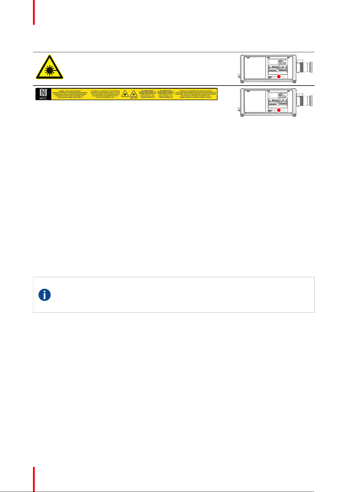
Notice on laser radiation
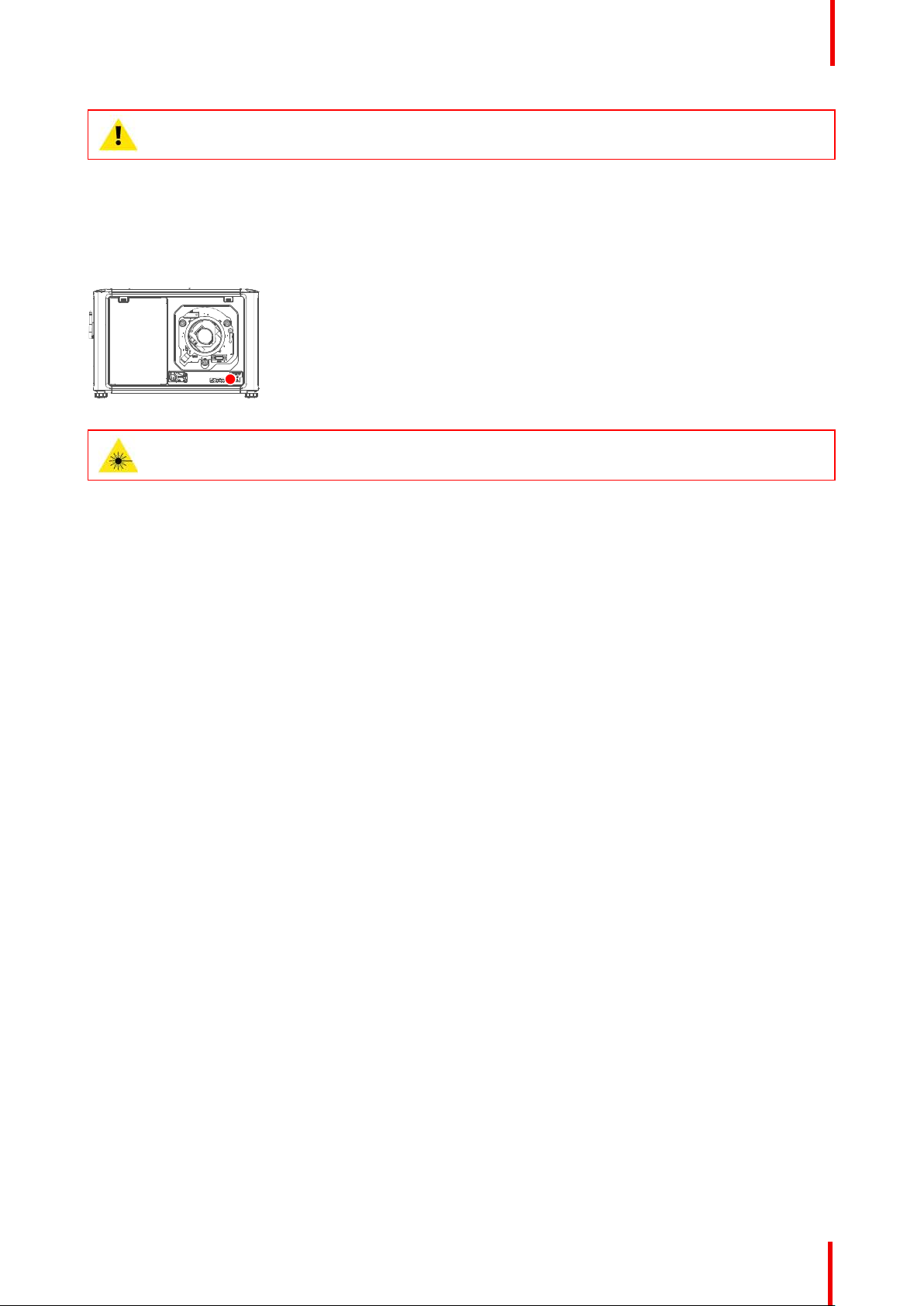
The laser distance meter that is optional equipment for this projector can emit a class 2 laser ranging beam of
0.95 mW / 638 nm. When installed correctly, this distance meter is located on the front side of the projector
(see ). The laser beam can be enabled by either pressing the button on the equipment, via the projector menu,
or via the projector software. Thermal retinal eye injury is possible when staring into the laser ranging beam.
Image 1-1
WARNING: Laser Radiation — Do not stare into laser ranging beam, Class 2 IEC EN 60825-1:2014
Users definition
Throughout this manual, the term SERVICE PERSONNEL refers to Barco authorized persons having
appropriate technical training and experience necessary to be knowledgeable of potential hazards to which
they are exposed (including, but not limited to HIGH VOLTAGE ELECTRIC and ELECTRONIC CIRCUITRY
and HIGH BRIGHTNESS PROJECTORS) in performing a task, and of measures to minimize the potential risk
to themselves or other persons. The term USER and OPERATOR refers to any person other than SERVICE
PERSONNEL, AUTHORIZED to operate professional projection systems.
The UDM projector is intended "FOR PROFESSIONAL USE ONLY" by AUTHORIZED PERSONNEL familiar
with potential hazards associated with high voltage, high intensity light beams and high temperatures
generated by the light source and associated circuits. Only qualified SERVICE PERSONNEL, knowledgeable
of such risks, are allowed to perform service functions inside the product enclosure.
1.2 Important safety instructions
To prevent risk of electrical shock
• This product should be operated from a mono phase AC power source. Ensure that the mains voltage and
capacity matches the projector electrical ratings: 120-180V / 200-240V (+/-10%), 16A-12A, 50-60Hz. If you
are unable to install the AC requirements, contact your electrician. Do not defeat the purpose of the
grounding.
• This apparatus must be grounded (earthed) via the supplied 3 conductor AC power cable.
• If none of the supplied power cables are the correct one, consult your dealer.
• If you are unable to insert the plug into the outlet, contact your electrician to replace your obsolete outlet.
Do not defeat the purpose of the grounding-type plug.
• Never use 2- wire power cords, as this is dangerous and could lead to electrical shock. Always use a
power connector with a ground terminal.
• Do not allow anything to rest on the power cord. Do not locate this product where persons will walk on the
cord. To disconnect the cord, pull it out by the plug. Never pull the cord itself.
• Use only the power cord supplied with your device. While appearing to be similar, other power cords have
not been safety tested at the factory and may not be used to power the device. For a replacement power
cord, contact your dealer.
• If you are unable to insert the plug into the outlet, contact your electrician to replace your obsolete outlet.
Do not defeat the purpose of the grounding-type plug.
• Do not operate the projector with a damaged cord. Replace the cord.
• Do not operate the projector if the projector has been dropped or damaged - until it has been examined
and approved for operation by qualified service personnel.
• Position the cord so that it will not be tripped over, pulled, or contact hot surfaces.
R5911443 /02 UDM 11
Page 12

Safety information
• If an extension cord is necessary, a cord with a current rating at least equal to that of the projector should
be used. A cord rated for less amperage than the projector may overheat.
• Never push objects of any kind into this product through cabinet slots as they may touch dangerous
voltage points or short out parts that could result in a risk of fire or electrical shock.
• Make sure that no objects enter into the vents and openings of the set.
• Do not expose this projector to rain or moisture.
• The projector is designed for indoor use only. Never operate the unit outdoors.
• Do not immerse or expose this projector in water or other liquids.
• Do not spill liquid of any kind on this projector.
• Should any liquid or solid object fall into the cabinet, unplug the set and have it checked by qualified
service personnel before resuming operations.
• Do not disassemble this projector, always take it to qualified service personnel when service or repair work
is required.
• Do not use an accessory attachment which is not recommended by the manufacturer.
• Lightning - For added protection for this video product during a lightning storm, or when it is left unattended
and unused for long periods of time, unplug it from the wall outlet. This will prevent damage to the device
due to lightning and AC power-line surges.
To prevent personal injury
• To prevent injury and physical damage, always read this manual and all labels on the system before
powering the projector or adjusting the projector.
• To prevent injury, take note of the weight of the projector. The weight of a basic projector is about 48 kg
(105 lb) without lens.
• To prevent injury, ensure that the lens and all covers are correctly installed. See installation procedures.
• Warning: high intensity light beam. NEVER look into the lens ! High luminance could result in damage to
the eye.
• Warning: extremely high brightness projector: This projector embeds extremely high brightness
(radiance) lasers; this laser light is processed through the projectors optical path. Native laser light is not
accessible by the end user in any use case. The light exiting the projection lens has been diffused within
the optical path, representing a larger source and lower radiance value than native laser light.
Nevertheless the projected light represents a significant risk for the human eye when exposed directly
within the beam. This risk is not specific related to the characteristics of laser light but solely to the high
thermal induced energy of the light source; which is comparable with lamp based systems.
Thermal retinal eye injury is possible when exposed within the Hazard Distance. The Hazard Distance
(HD) is defined from the projection lens surface towards the position of the projected beam where the
irradiance equals the maximum permissible exposure as described in the chapter “High Brightness
precautions: Hazard Distance”, page 16.
• High Brightness Warning: The projector light source may not be switched on or the shutter must be closed
when no projection lens is installed.
• Based on international requirements, no person is allowed to enter the projected beam within the zone
between the projection lens and the related Hazard Distance (HD). This shall be physically impossible by
creating sufficient separation height or by placing optional barriers. Within the restricted area operator
training is considered sufficient. The applicable separation heights are discussed in “High Brightness
precautions: Hazard Distance”, page 16.
• Warning: Laser radiation when optional laser distance meter is installed. Do not stare into laser ranging
beam. Class 2 laser beam could result in damage to the eye.
• Don’t put your hand in front of the beam.
• This product contains no user serviceable parts. Attempts to modify/replace mechanics or electronics
inside the housing or compartments will violate any warranties and may be hazardous. This kind of
operations shall only be performed by Barco authorized service personnel.
• Before attempting to remove any of the projector's covers, you must turn off the projector and disconnect
from the wall outlet.
• When required to switch off the projector, to access parts inside, always disconnect the power cord from
the power net.
• The power input at the projector side is considered as the disconnect device. When required to
switch off the projector, to access parts inside, always disconnect the power cord at the projector
side. In case the power input at the projector side is not accessible (e.g. ceiling mount), the socket
outlet supplying the projector shall be installed nearby the projector and be easily accessible, or a
readily accessible general disconnect device shall be incorporated in the fixed wiring.
• Do not stack or hang projectors without using the stacking frame.
R5911443 /02 UDM12
Page 13

Safety information
• Max units in stacked configuration, 3 units.
• Max units in hanging configuration, 2 units.
• When hanging projectors on a truss with the Barco stacking frame, always secure the stack with safety
cables between the projectors and the truss.
• When using the projector in a hanging configuration, always mount 2 safety cables. See installation
manual for the correct use of these cables.
• Do not place this equipment on an unstable cart, stand, or table. The product may fall, causing serious
damage to it and possible injury to the user.
• Only place the projector on a stable surface, or mount it securely using an approved ceiling mount rig.
• It is hazardous to operate without lens or shield. Always switch the output light off when replacing a lens.
• Lenses or shields shall be changed if they have become visibly damaged to such an extent that their
effectiveness is impaired. For example by cracks or deep scratches.
• Cooling liquid circuit. The projector contains a cooling circuit filled with Mono-ethylene glycol (1,2-ethane
diol) and inhibitors in aqueous solution (34% active). If the unlikely event that the cooling circuits have a
leak, switch off the device and contact qualified service personnel. The liquid is not for household use.
Keep out of reach of children. Harmful by oral intake. Avoid exposure to pregnant women. Avoid contact
with eyes, skin and clothing. Avoid inhale of the noxious fumes.
• Never point or allow light to be directed on people or reflective objects within the HD zone.
• All operators shall have received adequate training and be aware of the potential hazards.
• In case of using an external cooling system position the hoses of the cooling system so that they will not be
tripped over, pulled, or contact hot surfaces.
To prevent fire hazard
• Do not place flammable or combustible materials near the projector!
• Barco large screen projection products are designed and manufactured to meet the most stringent safety
regulations. This projector radiates heat on its external surfaces and from ventilation ducts during normal
operation, which is both normal and safe. Exposing flammable or combustible materials into close
proximity of this projector could result in the spontaneous ignition of that material, resulting in a fire. For this
reason, it is absolutely necessary to leave an “exclusion zone” around all external surfaces of the projector
whereby no flammable or combustible materials are present. The exclusion zone must be not less than 40
cm (16”) for this projector.
• Do not place any object in the projection light path at close distance to the projection lens output. The
concentrated light at the projection lens output may result in damage, fire or burn injuries.
• Ensure that the projector is solidly mounted so that the projection light path cannot be changed by
accident.
• Do not cover the projector or the lens with any material while the projector is in operation. . Mount the
projector in a well ventilated area away from sources of ignition and out of direct sun light. Never expose
the projector to rain or moisture. In the event of fire, use sand, CO
use water on an electrical fire. Always have service performed on this projector by authorized Barco
service personnel. Always insist on genuine Barco replacement parts. Never use non-Barco replacement
parts as they may degrade the safety of this projector.
• Slots and openings in this equipment are provided for ventilation. To ensure reliable operation of the
projector and to protect it from overheating, these openings must not be blocked or covered. The openings
should never be blocked by placing the projector too close to walls, or other similar surface. This projector
should never be placed near or over a radiator or heat register. This projector should not be placed in a
built-in installation or enclosure unless proper ventilation is provided.
• Projection rooms must be well ventilated or cooled in order to avoid build up of heat. It is necessary to vent
hot exhaust air from projector and cooling system to the outside of the building.
• Let the projector cool completely before storing. Remove cord from the projector when storing.
or dry powder fire extinguishers. Never
2
To prevent battery explosion
• Danger of explosion if battery is incorrectly installed.
• Replace only with the same or equivalent type recommended by the manufacturer.
• For disposal of used batteries, always consult federal, state, local and provincial hazardous waste disposal
rules and regulations to ensure proper disposal.
R5911443 /02 UDM 13
Page 14

Safety information
To prevent projector damage
• The air filters of the projector must be cleaned or replaced on a regular basis. Cleaning the booth area
would be monthly-minimum. Neglecting this could result in disrupting the air flow inside the projector,
causing overheating. Overheating may lead to the projector shutting down during operation.
• The projector must always be installed in a manner which ensures free flow of air into its air inlets.
• If more than one projector is installed in a common projection booth, the exhaust air flow requirements are
valid for EACH individual projector system. Note that inadequate air extraction or cooling will result in
decreased life expectancy of the projector as a whole as well as causing premature failure of the lasers.
• In order to ensure that correct airflow is maintained, and that the projector complies with Electromagnetic
Compatibility (EMC) and safety requirements, it should always be operated with all of it's covers in place.
• Slots and openings in the cabinet are provided for ventilation. To ensure reliable operation of the product
and to protect it from overheating, these openings must not be blocked or covered. The openings should
never be blocked by placing the product on a bed, sofa, rug, or other similar surface. This product should
never be placed near or over a radiator or heat register. The device should not be placed in a built-in
installation or enclosure unless proper ventilation is provided.
• Ensure that nothing can be spilled on, or dropped inside the projector. If this does happen, switch off and
remove all power from the projector. Do not operate the projector again until it has been checked by
qualified service personnel.
• Do not block the projector cooling fans or free air movement around the projector.
• Do not use this equipment near water.
• Special care for Laser Beams: Special care should be used when DLP projectors are used in the same
room as high power laser equipment. Direct or indirect hitting of a laser beam on to the lens can severely
damage the Digital Mirror Devices
• Never place the projector in direct sunlight. Sunlight on the lens can severely damage the Digital Mirror
Devices
TM
in which case there is a loss of warranty.
• Save the original shipping carton and packing material. They will come in handy if you ever have to ship
your equipment. For maximum protection, repack your set as it was originally packed at the factory.
• Unplug this product from the wall outlet before cleaning. Do not use liquid cleaners or aerosol cleaners.
Use a damp cloth for cleaning. Never use strong solvents, such as thinner or benzine, or abrasive
cleaners, since these will damage the cabinet. Stubborn stains may be removed with a cloth lightly
dampened with mild detergent solution.
• To ensure the highest optical performance and resolution, the projection lenses are specially treated with
an anti-reflective coating, therefore, avoid touching the lens. To remove dust on the lens, use a soft dry
cloth. For lens cleaning follow the instructions precisely as stipulated in the projector manual.
• Only use zoom lenses of the Barco TLD+ series on the 4K models of the projector. Using other lenses will
damage the internal optics. For suitable fixed TLD+ lenses contact Barco or see Barco website.
• Allowed ambient temperature range depends on altitude:
- between 0 and 1000 meter altitude: ambient temperature range = 0°C (32°F) to 40°C (104°F)
- between 1000 and 3000 meter altitude: ambient temperature range = 0°C (32°F) to 30°C (86°F)
• Rated humidity = 0% RH to 80% RH Non-condensed.
TM
in which case there is a loss of warranty.
On servicing
• Do not attempt to service this product yourself, as opening or removing covers may expose you to
dangerous voltage potentials and risk of electric shock.
• Refer all servicing to qualified service personnel.
• Attempts to alter the factory-set internal controls or to change other control settings not specially discussed
in this manual can lead to permanent damage to the projector and cancellation of the warranty.
• Remove all power from the projector and refer servicing to Barco authorized service personnel under the
following conditions:
- When the power cord or plug is damaged or frayed.
- If liquid has been spilled into the equipment.
- If the product has been exposed to rain or water.
- If the product does not operate normally when the operating instructions are followed. Adjust only those
controls that are covered by the operating instructions since improper adjustment of the other controls
may result in damage and will often require extensive work by a qualified technician to restore the
product to normal operation.
- If the product has been dropped or the cabinet has been damaged.
- If the product exhibits a distinct change in performance, indicating a need for service.
R5911443 /02 UDM14
Page 15
Safety information
• Replacement parts: When replacement parts are required, be sure the service technician has used original
Barco replacement parts or authorized replacement parts which have the same characteristics as the
Barco original part. Unauthorized substitutions may result in degraded performance and reliability, fire,
electric shock or other hazards. Unauthorized substitutions may void warranty.
• Safety check: Upon completion of any service or repairs to this projector, ask the service technician to
perform safety checks to determine that the product is in proper operating condition.
Stacking and transporting
• Stack maximum 2 rental flight cases high. Never higher.
• Surface on which flight case is standing must be level to ensure that the total load is evenly spread out
among the four wheels. The surface must also be able to support the load safely.
• Before stacking or transporting flight cases, check the wheels and their fixation screws for wear or defects.
• Before stacking or transporting flight cases, check that the four lock handles on each flight case are in
good working order and locked securely.
• When stacked, make sure the wheels of the upper flight case are precisely positioned in the stacking
dishes of the flight case below.
• Stacked flight cases may not be moved. Before stacking, the lower flight case must already be in its final
resting position before placing the second upon it.
• Never stack loaded flight cases in a truck or other transport medium, unless each flight case is rigidly
strapped tight.
• In the event of a wheel breaking, flight cases must be rigidly strapped tight to prevent a stack collapsing.
• Use an appropriate forklift to raise flight cases and take the necessary precautions to avoid personnel
injury.
Safety Data Sheets for Hazardous Chemicals
For safe handling information on chemical products, consult the Safety Data Sheet (SDS). SDSs are available
upon request via safetydatasheets@barco.com.
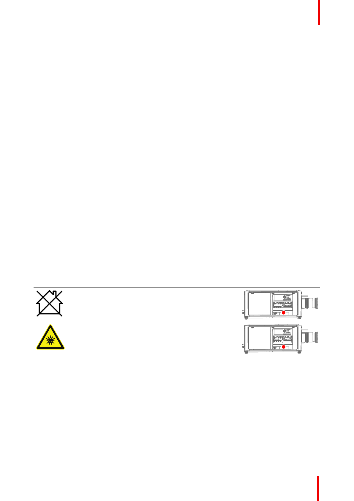
1.3 Product safety labels
Light beam related safety labels
Label image Label description
Hazard RG3: not for household use symbol
Hazard RG3: optical radiation warning symbol
Label location
R5911443 /02 UDM 15
Page 16
Safety information
Label image Label description
Hazard class 2: laser radiation warning symbol.
0.95 mW - 638 nm.
WARNING! DO NOT LOOK INTO THE BEAM NO DIRECT EYE EXPOSURE
TO THE PROJECTOR BEAM IS PERMITTED LASER RADIATION - DO
NOT STARE INTO LASER RANGING BEAM RG3 IEC EN 62471-5:2015
CLASS 2 IEC EN 60825-1:2014 HAZARD DISTANCE: CONSULT SAFETY
MANUAL
THIS PRODUCT IS IN CONFORMITY WITH PERFORMANCE
STANDARDS FOR LASER PRODUCTS UNDER 21 CFR 1040, EXCEPT
WITH RESPECT TO THOSE CHARACTERISTICS AUTHORIZED BY
VARIANCE NUMBER 2016-V-0144 EFFECTIVE ON DECEMBER 12, 2019.
警告!勿觀看投影機光束 眼睛勿直接接觸可允許暴露的光束 鐳射輻射-勿直視
鐳射範圍內光束 RG3 IEC EN 62471-5:2015 CLASS 2 IEC EN 60825-1:
2014 危害距離:請參考安全手冊
警告!勿观看投影机光束 眼睛勿直接接触可允许暴露的光束 激光辐射-勿直视
激光范围内光束 RG3 IEC EN 62471-5:2015 CLASS 2 IEC EN 60825-1:
2014 危害距离:请参考安全手册
ATTENTION! NE PAS REGARDER LE FAISCEAU DU PROJECTEUR
EVITER TOUTE EXPOSITION DIRECTE DES YEUX AU FAISCEAU DU
PROJECTEUR RAYONNEMENT LASER - NE PAS REGARDER DANS LE
FAISCEAU DU TELEMETRE RG3 IEC EN 62471-5:2015 CLASS 2 IEC EN
60825-1:2014 DISTANCE DE SECURITE: CONSULTER LE MANUEL DE
SECURITE
Label location
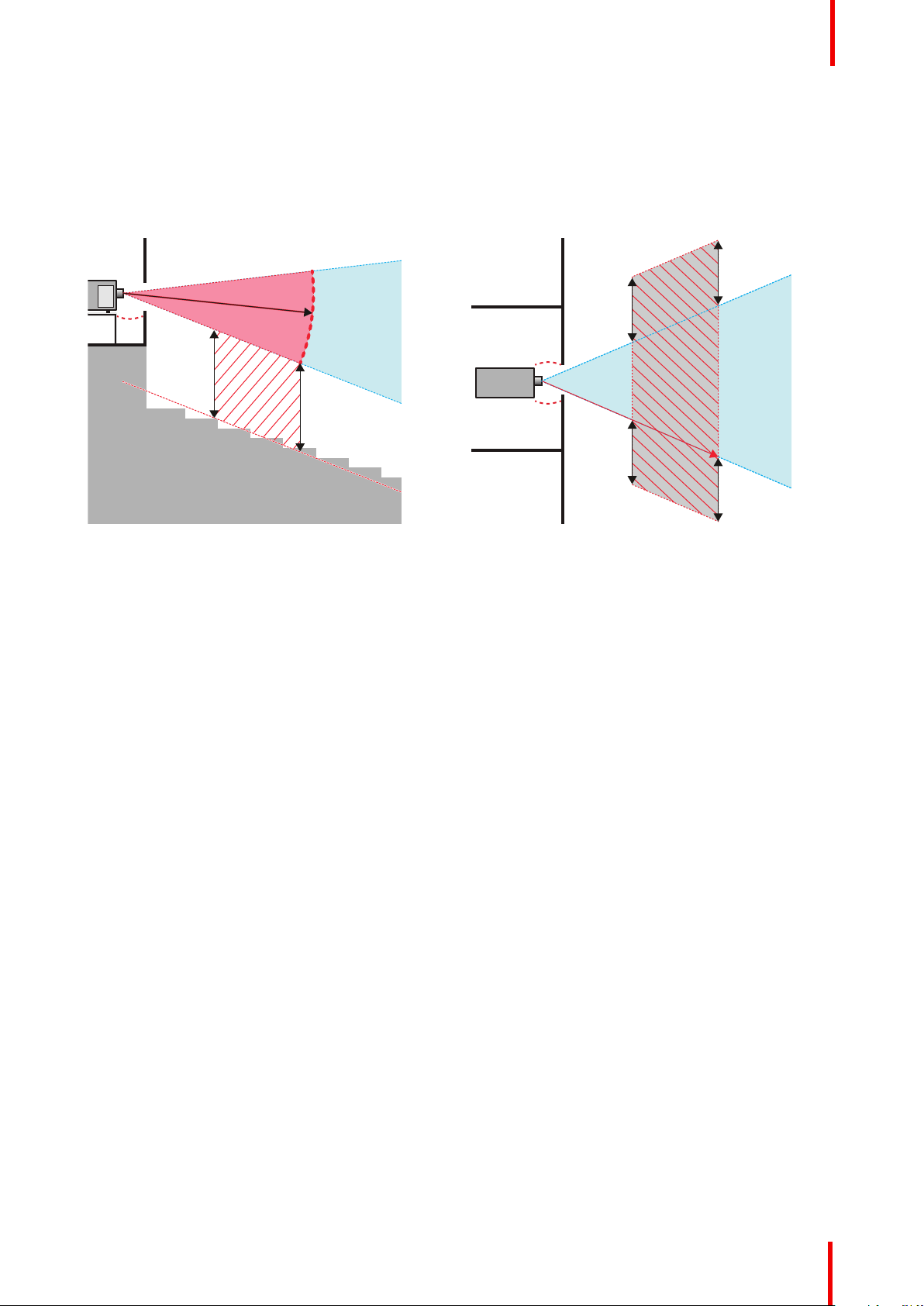
1.4 High Brightness precautions: Hazard Distance
HD
Hazard Distance (HD) is the distance measured from the projection lens at which the intensity or the
energy per surface unit becomes lower than the applicable exposure limit on the cornea or on the
skin. The light beam is considered (to be) unsafe for exposure if the distance from a person to the
light source is less than the HD.
Restriction Zone (RZ) based on the HD
The HD depends on the amount of lumens produced by the projector and the type of lens installed. See
chapter “HD in function of modifying optics”, page 20.
To protect untrained end users (as cinema visitors, spectators) the installation shall comply with the following
installation requirements: Operators shall control access to the beam within the hazard distance or install the
product at the height that will prevent spectators' eyes from being in the hazard distance. Radiation levels in
excess of the limits will not be permitted at any point less than 2.0 meter (SH) above any surface upon which
persons other than operators, performers, or employees are permitted to stand or less than 1.0 meter (SW)
lateral separation from any place where such persons are permitted to be. In environments where
unrestrained behavior is reasonably foreseeable, the minimum separation height should be greater than or
equal to 3.0 meter to prevent potential exposure, for example by an individual sitting on another individual's
shoulders, within the HD.
These values are minimum values and are based on the guidance provided in IEC 62471-5:2015 section
6.6.3.5.
The installer and user must understand the risk and apply protective measures based upon the hazard
distance as indicated on the label and in the user information. Installation method, separation height, barriers,
detection system or other applicable control measure shall prevent hazardous eye access to the radiation
within the hazard distance.
R5911443 /02 UDM16
Page 17
RA
TH
PR
RZ
HD
SW
1m
SW
SW
SW
HD
EXIT
SH
RA
TH
RZ
SH
(B) TOP VIEW(A) SIDE VIEW
Safety information
For example, projectors that have a HD greater than 1 m and emit light into an uncontrolled area where
persons may be present should be positioned in accordance with “the fixed projector installation” parameters,
resulting in a HD that does not extend into the audience area unless the beam is at least 2.0 meter above the
floor level. In environments where unrestrained behavior is reasonably foreseeable, the minimum separation
height should be greater than or equal to 3.0 meter to prevent potential exposure, for example by an individual
sitting on another individual's shoulders, within the HD. Sufficiently large separation height may be achieved
by mounting the image projector on the ceiling or through the use of physical barriers.
Image 1-2
A
Side view.
B
Top view.
RA
Restricted Access location (boot area of
projector).
PR
Projector.
TH
Theater.
RZ
Restriction Zone in the theater.
SH
Separation Height.
SW
Separation Width.
Based on national requirements, no person is allowed to enter the projected beam within the zone between
the projection lens and the related hazard distance (HD). This shall be physically impossible by creating
sufficient separation height or by placing barriers. The minimum separation height takes into account the
surface upon which persons other than operator, performers or employees are permitted to stand.
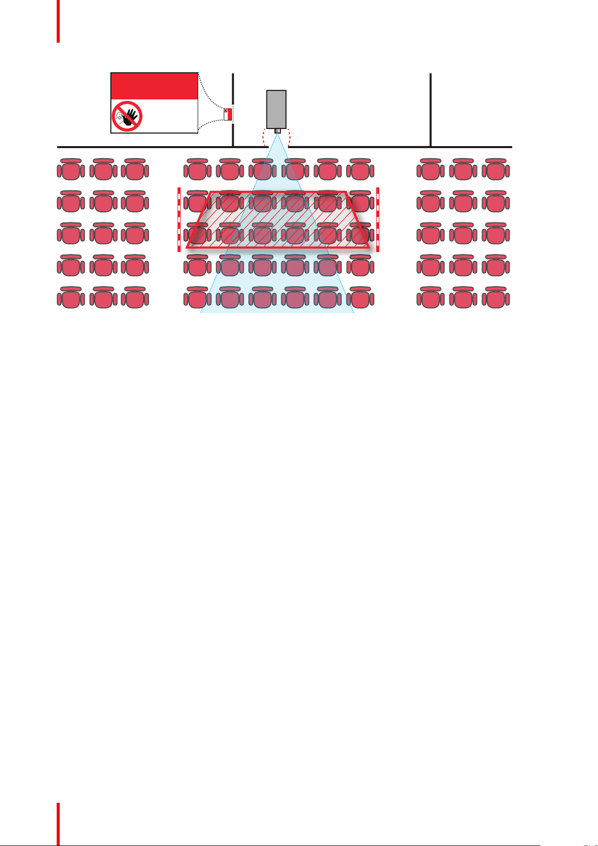
On Image 1-3 a typical setup is displayed. It must be verified if these minimum requirements are met. If
required a restricted zone (RZ) in the theater must be established. This can be done by using physical barrier,
like a red rope as illustrated in Image 1-3.
The restricted area sticker can be replaced by a sticker with only the symbol.
R5911443 /02 UDM 17
Page 18
PR
RESTRICTED
AREA
RESTRICTED
AREA
Safety information
Image 1-3
USA market
For LIPs (Laser Illuminated Projectors) installed in the USA market other restriction zone conditions apply.
LIPs for installation in restrained environment (cinema theaters, business rooms, class rooms, museums ...)
shall be installed at height vertically above the floor such that the bottom plane of the hazard distance zone
shall be no lower than 2.5 meters above the floor. Horizontal clearance to the hazard distance zone shall be
not less than 1 meter. Alternatively, in case the height of the separation barrier for the horizontal clearance is
at least 1 meter high then the horizontal clearance (SW) can be reduced to:
• 0 meter if the height of the hazard zone is minimum 2.5 meter.
• 0.1 meter if the height of the hazard zone is minimum 2.4 meter.
• 0.6 meter if the height of the hazard zone is minimum 2.2 meter.
LIPs for installations in unrestrained environment (concerts, ...) shall be installed at a height vertically above
the floor such that the bottom plane of the Hazard distance Zone shall be no lower than 3 meters above the
floor. Horizontal clearance to the hazard distance zone shall be not less than 2.5 meters. Any human access
horizontally to the Hazard Zone, if applicable, shall be restricted by barriers. If human access is possible in an
unsupervised environment, the horizontal or vertical clearances shall be increased to prevent exposure to the
hazard distance zone.
The LIP shall be installed by Barco or by a trained and Barco-authorized installer or shall only be transferred to
laser light show variance holders. This is applicable for dealers and distributors since they may need to install
the LIP (demo install) and/or they transfer (sell, rent, lease) the LIP. Variance holders may currently hold a
variance for production of Class IIIB and IV laser light shows and/or for incorporating RG3 LIPs. Laser light
show variance can be requested via the FDA online eSubmitter portal or via FDA Form 3147 referencing to
Barco’s variance approval 2016-V-0144.
The installation checklist for laser illuminated RG3 projectors must be fully completed after the installation.
The installation checklist can be downloaded from the Barco website. The last variance holder in the
distribution chain is responsible to maintain the installation checklist and to make it available on request of the
FDA. In case Barco is the last variance holder the checklist must be sent to pvg@barco.com.
In addition to temporary installations (e. g.: rental and staging, lease, events …) the following requirements
apply:
• Rental companies shall have a laser light show variance because they have direct relationship with the
installers of the rented equipment.
• This product shall be located in such a way that all propagating beam paths within the Restriction Zone,
and the audience can be directly observed at all times.
• Communication shall be maintained with other personnel assisting in surveillance of the LIP projection.
R5911443 /02 UDM18
Page 19
RA TH
sw
PD
HD
DIFFUSE
sw
RZ
sw
sw
PR
HD
REFLECTION
RESTRICTED
AREA
RESTRICTED
AREA
Safety information
• In the event of any unsafe condition, immediately terminates (or designate the termination) of LIP
projection light.
Install one or more readily accessible controls to immediately terminate LIP projection light. The power input at
the projector side is considered as a reliable disconnect device. When required to switch off the projector,
disconnect the power cord at the projector side. In case the power input at the projector side is not accessible
(e. g. truss mount), the socket outlet supplying the projector shall be installed nearby the projector and be
easily accessible, or a readily accessible general disconnect device shall be incorporated in the fixed wiring.
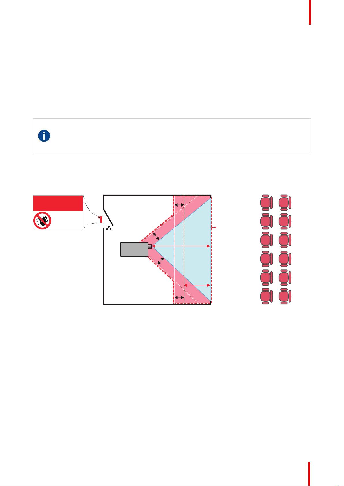
1.5 HD for fully enclosed projection systems
HD
Hazard Distance (HD) is the distance measured from the projection lens at which the intensity or the
energy per surface unit becomes lower than the applicable exposure limit on the cornea or on the
skin. The light beam is considered (to be) unsafe for exposure if the distance from a person to the
light source is less than the HD.
Restriction Zone (RZ) based on the HD
The projector is also suitable for rear projection applications; projecting a beam onto a defuse coated
projection screen. As displayed in Image 1-4 two areas should be considered: the restricted enclosed
projection area (RA) and the observation area (TH).
Image 1-4
RA
Restricted Access location (enclosed projection
area).
PR
Projector.
TH
Theater (observation area).
For this type of setup 3 different HD shall be considered:
• HD as discussed in “High Brightness precautions: Hazard Distance”, page 16, relevant for intrabeam
exposure.
• HD
screen.
• HD
screen.
As described in “High Brightness precautions: Hazard Distance”, page 16, it is mandatory to create a
restricted zone within the beam areas closer than any HD. In the enclosed projection area the combination of
two restricted zones are relevant: The restricted zone of the projected beam toward the screen; taking into
account 1 meter Separation Width (SW) from the beam onward. Combined with the restricted zone related to
the rear reflection from the screen (HD
RZ
Restriction Zone.
PD
Projection Distance.
SW
Separation Width. Must be minimum 1 meter.
: the distance that has to be kept restrictive related to the reflected light from the rear projection
reflection
: the relevant distance to be considered while observing the diffuse surface of the rear projection
diffuse
); also taking into account a 1 meter lateral separation.
reflection
R5911443 /02 UDM 19
Page 20
0
1
2
3
4
5
6
7
8
9
10
11
12
13
1
1,2
1,4
1,6
1,8
2,0
2,2
2,4
2,6
2,8
3,0
3,2
3,4
3,6
3,8
4,0
4,2
4,4
4,6
4,8
5,0
5,2
5,4
5,6
5,8
6,0
6,2
6,4
6,6
6,8
7,0
7,2
7,4
7,6
7,8
8,08,2
8,4
8,6
8,8
9,0
9,2
9,4
9,6
9,8
10,0
Hazard distance (HD) [m]
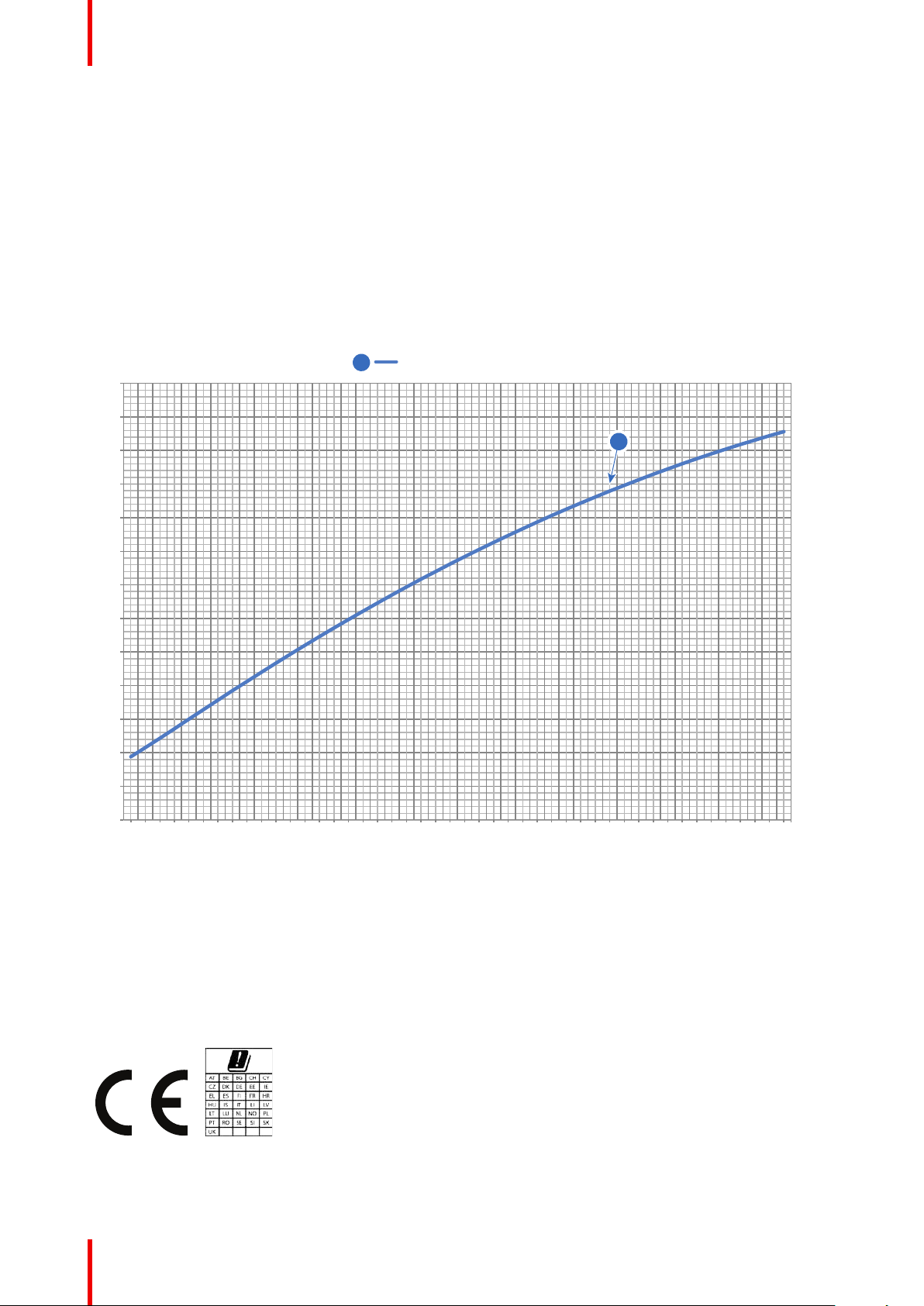
Throw Ra!o (TR)
UDM
1
1 2
Safety information
The HD
reflection
distance equals 25% of the difference between the determined HD distance and the projection
distance to the rear projection screen. To determine the HD distance for the used lens and projector model see
chapter “HD in function of modifying optics”, page 20.
HD
reflection
= 25% (HD – PD)
The light emitted from the screen within the observation shall never exceed the RG2 exposure limit,
determined at 10 cm. The HD
can be neglected if the measured light at the screen surface is below 5000
diffuse
cd/m² or 15000 LUX.
1.6 HD in function of modifying optics
Hazard distance
Image 1-5
HD
Hazard Distance
TR
Throw Ratio
1.7 Radio equipment (optional)
CE Conformity
The UDM may be equipped with WiFi & GSM modules for Pulse Input &
Communication unit, which are fit for use in the European Economic Area
(EEA).
The UDM is restricted to indoor use only when operating in the 5150 to
R5911443 /02 UDM20
5250 MHz frequency range.
Page 21

Safety information
Hereby, Barco declares that the radio equipment type UDM is in compliance with Directive 2014/53/EU. The
full text of the EU declaration of conformity is available at the following internet address:
https://www.barco.com/support
WiFi & GSM module
For WLAN:
• Frequency: 2402 MHz - 2482 Mhz
• Max EIRP: 19 dBm
• Frequency: 5150 – 5350 MHz / 5470 – 5725 Mhz
• Max EIRP: 23 dBm
For GSM:
• E-GSM:
- Frequency: 900 MHz
- Max EIRP: 33.5 dBm
• EDGE:
- Frequency: 900 MHz
For UMTS:
• Band 1:
- Frequency: 2100 MHz
- Max EIRP: 24 dBm
• Band 8:
- Frequency: 900 MHz
- Max EIRP: 24 dBm
- Max EIRP: 28 dBm
• DCS:
- Frequency: 1800 MHz
- Max EIRP: 30.5 dBm
• EDGE:
- Frequency: 1800 MHz
- Max EIRP: 27 dBm
R5911443 /02 UDM 21
Page 22

Safety information
R5911443 /02 UDM22
Page 23

Getting Started 2
2.1 Getting to know the projector .........................................................................................................24
2.2 Power on the projector ..................................................................................................................26
2.3 Start image projection ...................................................................................................................27
2.4 Switching to standby .....................................................................................................................29
2.5 Power off projector........................................................................................................................ 29
About this chapter
This chapter and by extension this whole document, the user manual, is intended for the user who want’s to
operate the projector. It does not contain installation instructions because the installation has to be done by
trained and qualified service technicians. Refer to the projector installation manual for detailed installation
instructions.
R5911443 /02 UDM
23
Page 24
T
L
F
R
B
65
1
2 3 4 7 8
Getting Started
2.1 Getting to know the projector
Orientation convention
This manual refers to the left side of the projector as the side at your left hand when standing behind the
projector and looking at the projection screen in front of the projector.
Image 2-1
T
Top
L
Left
F
Front
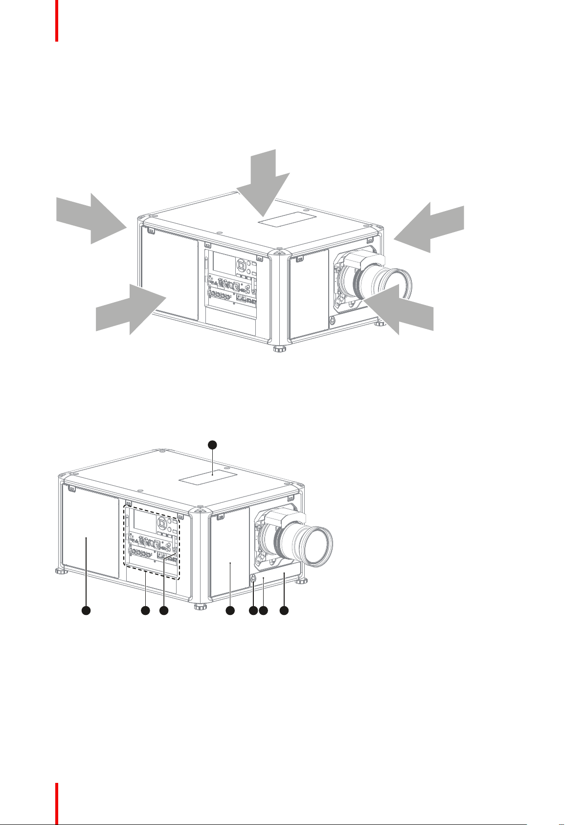
Projector component location
Image 2-2
1
Dust filter top air inlet
2
Dust filter side air inlet
3
Input & Communication
module
4
IR receiver projector right
side
5
Dust filter front air inlet
6
Auxiliary connector (for
external shutter, DMX, ...)
7
IR receiver projector front
side
8
Distance meter (optional)
R
Right
B
Back
R5911443 /02 UDM24
Page 25
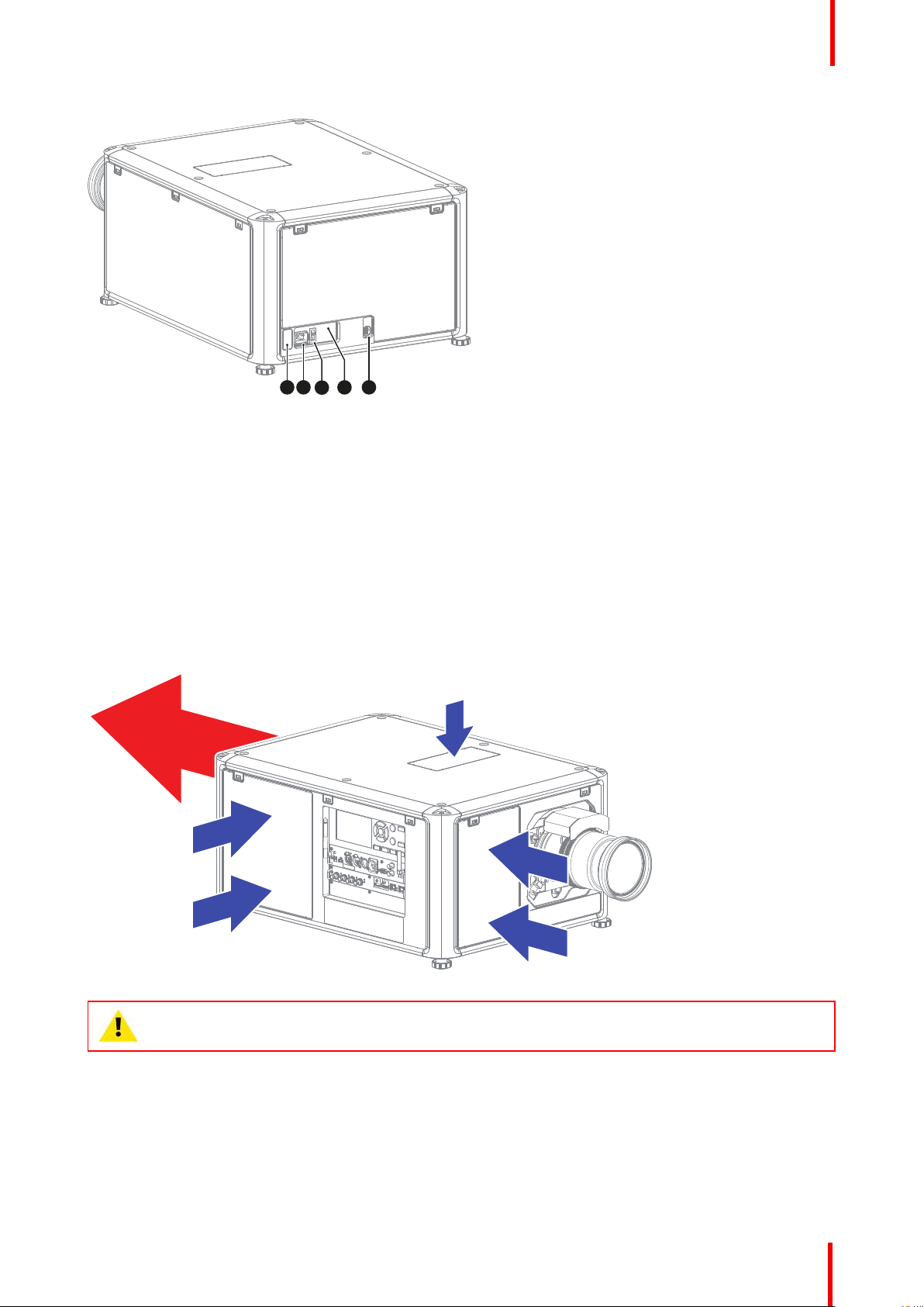
9 10
11
13
OVERVOLTAGE
12
Image 2-3
Getting Started
9
IR receiver projector
rear side
10
Mains power input
socket (for C19 plug)
11
Power ON/OFF switch
12
Overvoltage status light
13
USB port (to control
motorized rigging
frame)
For detailed info about the Input & Communication module see chapter “Input & Communication”, page 39.
Projector airflow
The projector has three air inlets: one at the top, one at the front and one at the right side of the projector.
Each air inlet is equipped with a dust filter. For cleaning/replacement instructions see chapter “Product
maintenance”, page 139.
There is only one air outlet which is located at the rear of the projector.
Image 2-4
CAUTION: Keep the air inlets and outlet at all times free. Make sure there is a
minimum distance of 60 cm (23.6 in) between the air outlet and the nearest solid object.
Projector Infra Red receivers and Remote Controle Unit
The projector has three Infra Red receivers: one at the rear (next to the power input), one at the front (below
the lens holder) and one at the right side (integrated in the Input & Communication module).
Point the Remote Controle Unit (RCU) directly to the Infra Red (IR) receiver. Make sure you are within the
effective operating distance (30 m, 100 ft in a straight line)
R5911443 /02 UDM 25
Page 26
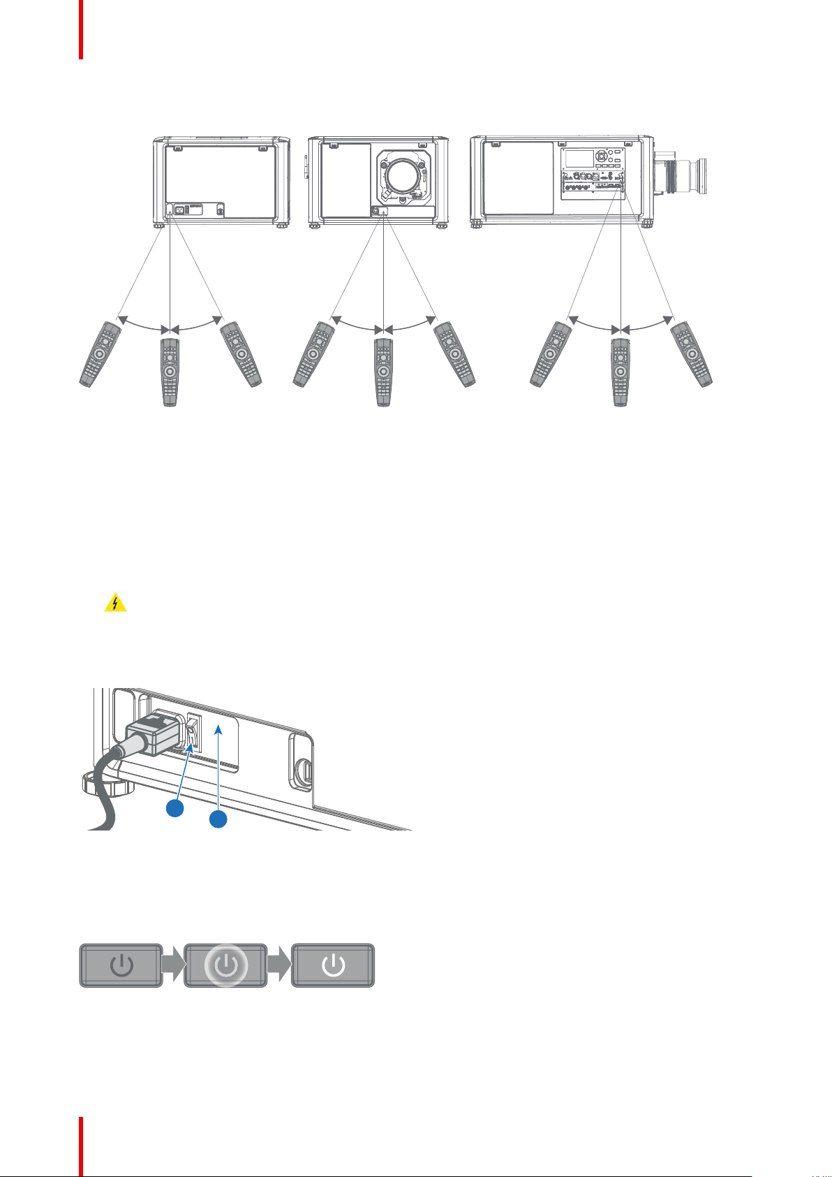
45°
45°
45°
45°
45°
45°
2
1
OVERVOLTAGE
Getting Started
The RCU will not function properly if strong light strikes the IR sensor window or if there are obstacles
between the RCU and the IR sensor.
Image 2-5
For detailed info about the RCU see chapter “Pulse Remote Control Unit”, page 31.
2.2 Power on the projector
How to power on
1. Does the OVERVOLTAGE status light (reference 1) lit up?
► If yes, pull out the power cord immediately. Contact a qualified technician to check the power net.
Warning: Never switch on the projector if the OVERVOLTAGE status light lit up. Neglecting will cause
irreversible damage to the projector.
► If no, proceed with the next step.
2. Press the mains switch (reference 2) to switch on this projector.
Image 2-6
• When '0' is pressed, the projector is switched off.
• When 'I' is pressed, the projector is switched on.
The projector starts up to standby mode. The Power on/off button will blink until standby mode is achieved.
Once in standby mode, the Power on/off button will be lit WHITE, but the display will be off.
Image 2-7
3. Press the Power on/off button on the projector, or the Power On button on the remote control.
The projector will continue to power on mode. The Power on/off button will blink until the projector is ready.
Once the projector is ready, the Power button will be lit BLUE.
R5911443 /02 UDM26
Page 27
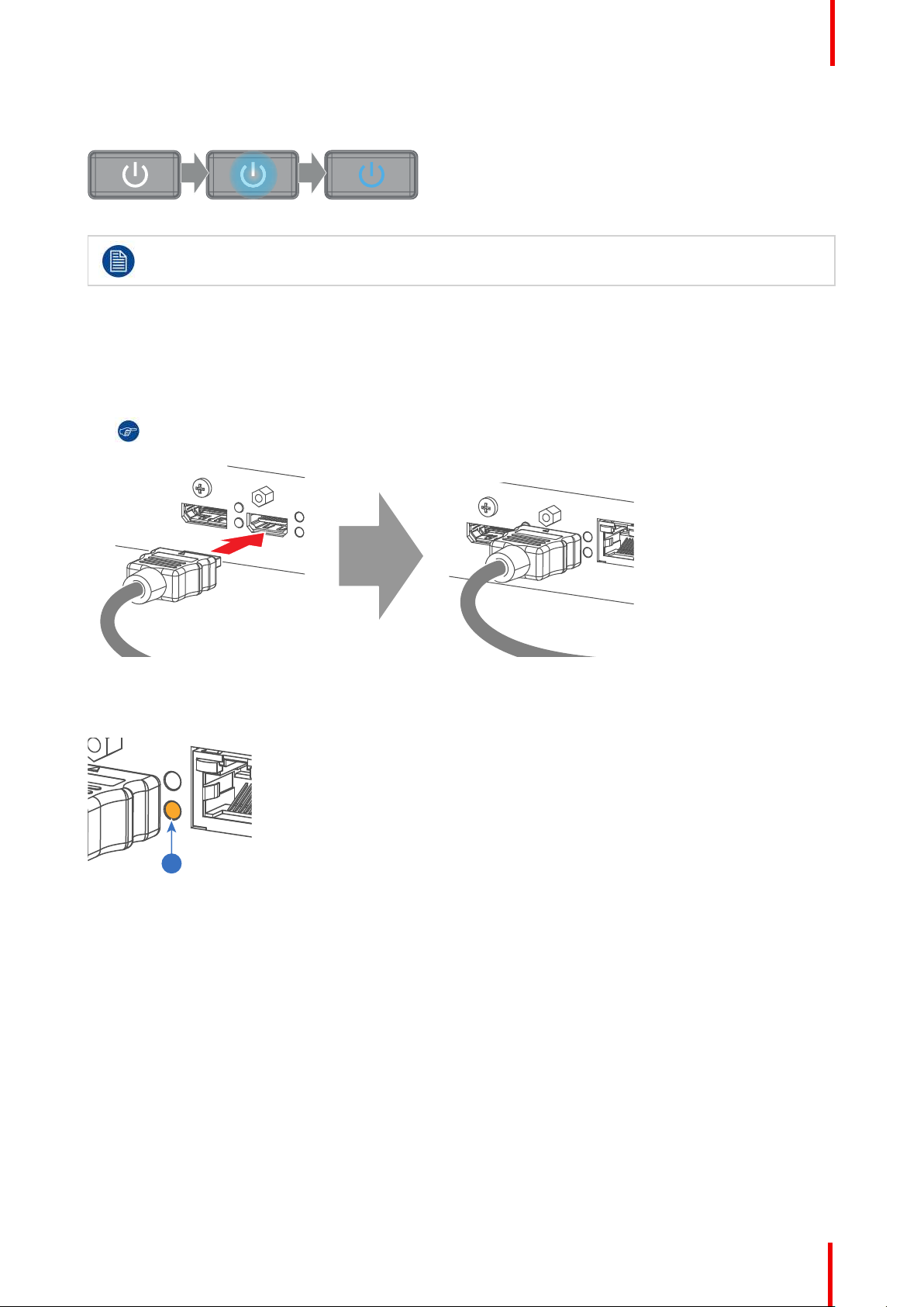
1
Getting Started
The start up screen is displayed on the touch panel and when fully started up, it changes to the overview
screen.
Image 2-8
The background image of the startup screen and info screens can be changed with Projector
Toolset with an installed UDM plug-in.
2.3 Start image projection
Connect the source
1. Connect the source cable with the appropriate input port on the Input & Communication module.
Tip: See chapter “Input & Communication”, page 39, for more info about supported input formats.
Image 2-9: Example of connecting an HDMI source.
2. Check if the SYNC LED lit up ORANGE (reference 1). This indicates that the sync is detected on the input
signal.
Image 2-10
Select the source
1. Press the Input button (reference I ) on the remote control or local keypad.
R5911443 /02 UDM 27
Page 28
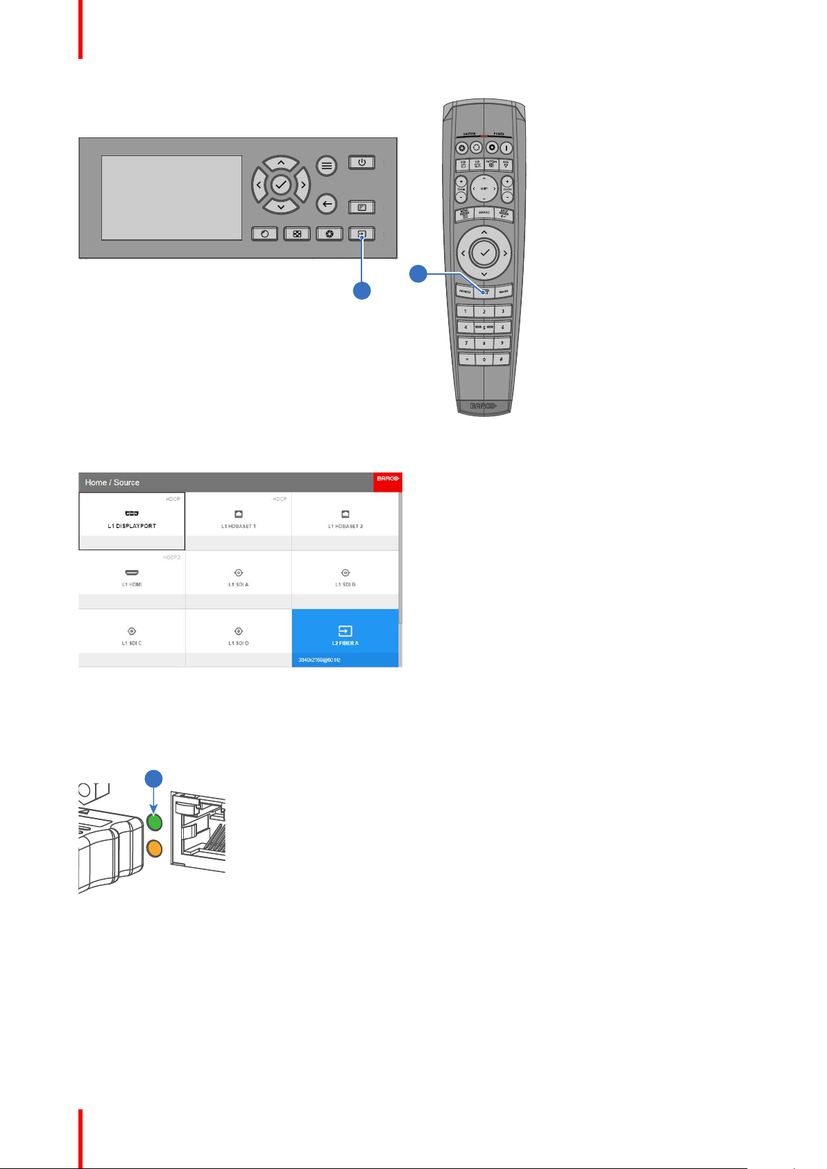
I
I
2
Getting Started
Image 2-11
The Source selection menu opens on the LCD display.
Image 2-12
2. Use the arrow keys to select the desired source.
• the SEL LED (reference 2) of the selected source lit up GREEN, and
• the image of the selected source is projected.
Image 2-13
Quick test pattern selection
1. Press the Test pattern button (references P) on the remote control or local keypad.
R5911443 /02 UDM28
Page 29
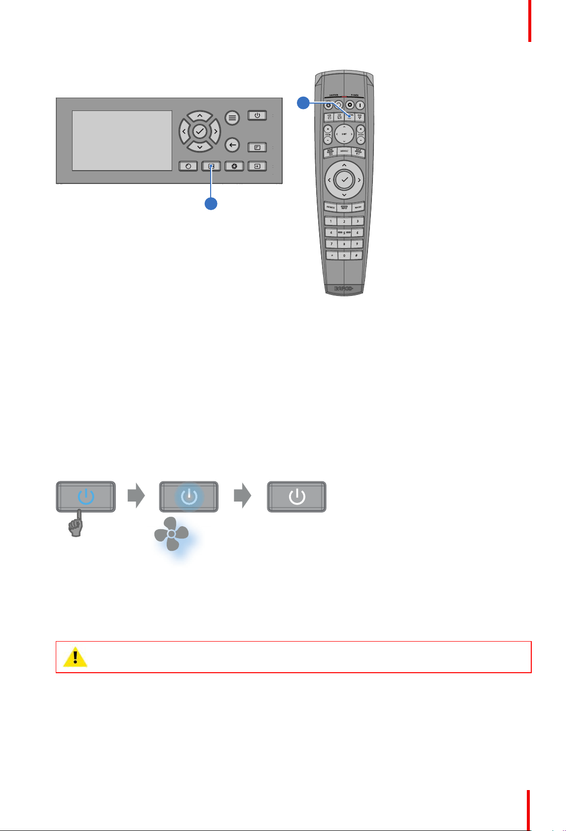
P
P
Image 2-14
3 s 30 s
The Test pattern menu opens on the LCD display.
Getting Started
2. Use the arrow keys to select the desired test pattern.
2.4 Switching to standby
How to switch to standby
1. Press and hold the Power on/off button for 3 seconds on the local keypad, or press the Power Off button on
the remote control.
The projector goes to standby mode. The after-cooling cycle will start (about 30 seconds). During this period
the Power on/off button will blink. Once the after-cooling cycle has ended, the projector will be in standby
mode and the Power on/off button will be lit WHITE.
Image 2-15
2.5 Power off projector
CAUTION: This procedure assumes the projector is in standby mode.
How to power off
1. Switch off the projector with the mains switch. '0' must be pressed.
R5911443 /02 UDM 29
Page 30
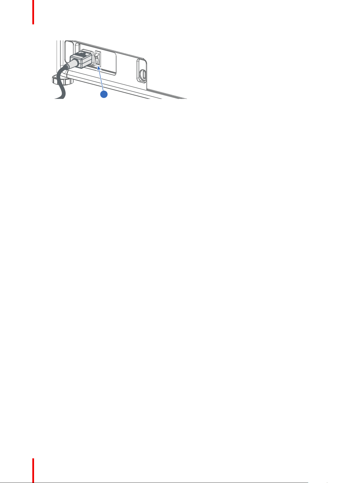
1
Getting Started
Image 2-16: Mains switch
2. Unplug the power cord from the projector.
R5911443 /02 UDM30
Page 31

Pulse Remote Control Unit
3.1 Remote control, battery installation ................................................................................................32
3.2 Remote control, protocol setup ...................................................................................................... 33
3.3 Remote control, on/off button......................................................................................................... 33
3.4 Using the RCU .............................................................................................................................34
3.5 Functionality overview...................................................................................................................35
3.6 Functions of the “button pressed indicator” ..................................................................................... 35
3.7 Function of the RGB filter button ....................................................................................................36
3.8 Displaying and Programming addresses into the RCU.....................................................................36
3.9 Using the XLR connector of the RCU ............................................................................................. 36
3.10 Using the mini-jack connector of the RCU....................................................................................... 37
3.11 Silicone protection sleeve for the RCU (optional)............................................................................. 37
3
R5911443 /02 UDM
31
Page 32

1
2
+
-
-
+
+
-
-
+
1
2
Pulse Remote Control Unit
3.1 Remote control, battery installation
Where to find the batteries for the remote control ?
The batteries are not placed in the remote control unit to avoid control operation in its package, resulting in a
shorter battery life time. At delivery the batteries can be found in a separated bag attached to the remote
control unit. Before using your remote control, install the batteries first.
How to install
1. Push the battery cover tab with the fingernail a little backwards (1) and pull, at the same time, the cover
upwards (2).
Image 3-1
2. Insert the two AA size batteries, making sure the polarities match the + and - marks inside the battery
compartment.
Tip: Use alkaline batteries for optimum range and life time.
Image 3-2
3. Insert (1) both lower tabs of the battery cover in the gaps at the bottom of the remote control, and press (2) the
cover until it clicks in place.
Image 3-3
R5911443 /02 UDM32
When replacing batteries, the broadcast address of the RCU will be reset to its default value '0'.
Page 33

Pulse Remote Control Unit
CAUTION: Replace with the correct battery type. Use two AA size batteries. There is a risk of
explosion if the battery is replaced with an incorrect type.
CAUTION: Replace the battery as explained above. There is a risk of explosion if the battery is
incorrectly installed.
3.2 Remote control, protocol setup
About the used protocol
The protocol is the code send out by the remote control when a button is pressed. Depending on this code, the
projector can decode the signals. The remote control can be used with two different protocols: RC5 and NEC.
Depending on the projector to control the remote control can be switched between these protocols.
Which protocol to use
• The NEC protocol has to be used for Barco projectors based on the Pulse platform: F70, F80, F90, HDX
4K, UDX, UDM, XDL, etc.
• The RC5 protocol has to be used all legacy Barco projectors: HDQ 2k40, HDF, HDX W, etc.
How to set
1. Remove the cover. For more info on how to remove, see “Remote control, battery installation”, page 32.
2. Place the switch in the desired position.
Image 3-4
Remarks when using the RC5 protocol
Due to new or updated functionality not all buttons of the Pulse RCU are one-to-one compatible with the
legacy Barco RCU and projectors. Take the following limitations into account:
• Buttons Shutter open and Shutter close emit the same code when in RC5 mode. This because the
legacy RCU’s only had 1 button for Shutter functionality.
• Buttons Power on and Power off emit the same code when in RC5 mode. This because the legacy RCU’s
only had 1 button for Power functionality.
• The RGB filter button is not supported.
• The Input selection button is not supported.
• The Default value button is not supported.
• The Macro button is not supported.
3.3 Remote control, on/off button
Purpose of the remote control on/off button
The Pulse remote control unit has at the front side an on/off switch (reference 1 Image 3-5). Switching off the
remote control prevents that unwanted commands are send due to an accidental key press. Furthermore,
switching the RCU off will extend the battery life time of the remote control.
R5911443 /02 UDM 33
Page 34

1
Pulse Remote Control Unit
To activate the remote control press the on/off button.
To deactivate the remote control press the on/off button again.
Default when (re)placing batteries, is “ON”.
Image 3-5
3.4 Using the RCU
Pointing to the reflective screen or IR sensors
Switch on the RCU and point the front of the RCU to the reflective screen surface or point directly to one of the
projector IR sensors. Make sure you are within the effective operating distance (30 m, 100 ft in a straight line).
The RCU will not function properly if strong light strikes the IR sensor window or if there are obstacles
between the RCU and the IR receiver.
Image 3-6
The RCU can also hard-wired been used. See chapter “Using the XLR connector of the RCU”, page 36.
Using the RCU in combination with a 3D emitter
When using a 3D emitter that radiates IR beams (e.g. the optional 3D emitter that Barco provides), the IR
beams of the 3D emitter may interfere with the IR communication between projector and the RCU.
If such interference occurs, connect the RCU to the projector using the remote cable with XLR connector. It is
also be advised to turn the IR receivers of the projector off to avoid the 3D emitter interference. The IR
receivers can be turned off in the GUI: System Settings > Communication > IR Control .
R5911443 /02 UDM34
Page 35

3.5 Functionality overview
1
2
3
4
5
6
7
8
9
10
11
12
15
24
23
22
21
20
19
18
17
16
13
14
2625
Remote Control Unit buttons
Pulse Remote Control Unit
Image 3-7
1
Button pressed indicator
2
Shutter open
3
Shutter close
4
LCD panel on / off
5
Project OSD on / off
6
Lens zoom
7
Lens shift
8
Menu open / close
9
Menu selection, OK button
10
Menu navigation
11
Input selection
12
Address button
13
Numeric buttons
3.6 Functions of the “button pressed indicator”
Functions button pressed indicator
• Rapidly flashes when commands are sent, this is the normal “button pressed” indication.
• 1 Short flash when remote control is switched ON by means of the on/off button.
• Continuously lit (up to 5 seconds) when address digits are expected after pressing the ADDR button.
14
Backspace (while entering values)
15
XLR connector
16
Decimal mark (while entering values)
17
Macro button
18
Menu back
19
Default value button
20
Lens focus
21
RGB filter
22
Test patterns
23
Power on
24
Power off
25
3.5 mm jack
26
RCU on / off
• Slowly flashes (2 times a second) when the battery level is becoming low; typically when more than 85% of
the useful life is past.
R5911443 /02 UDM 35
Page 36

Pulse Remote Control Unit
3.7 Function of the RGB filter button
Filtering the color of the projected image
By pressing the RGB filter button on the RCU you can place a color filter on the output of the projector. This
feature can be useful during the installation and configuration of a multi-projector or multi-channel setup. By
having one projector project a red image and another project a green image, it is easier to spot and adjust the
overlap section.
By pressing this button multiple times, you will have different active filters, in the following cycle:
• Red + Green + Blue (default)
• Red only
• Green only
• Blue only
• Red + Green
• Green + Blue
• Red + Blue
• Red + Green + Blue
• etc
After powering up, the colors will always revert back to full RGB.
3.8 Displaying and Programming addresses into the RCU
Displaying the Projector Address on the Screen.
1. If the projector is on, press the menu key and navigate to the Status page. The projector address and the
broadcast address can be seen under the Communication heading.
The projector's address is displayed on the LCD status screen and / or the OSD.
How to Program an Address into the RCU?
1. Press the Address button until the Button pressed indicator lights up continuously (proximately 5 seconds).
2. Enter the address with the digit buttons within the time the indicator lights up (also proximately 5 seconds).
Note: That address can be any value between 0 and 31.
Tip: A few examples:
To enter address 3, press "3" digit button on the RCU to set the RCU's address to 3 and wait until the
button pressed indicator is out. Alternatively, you can also press “0” and “3”. This way, the button
pressed indicator goes out immediately.
To enter address 31, then press “3” and “1” on the digit button on the RCU and the button pressed
indicator goes out immediately.
3.9 Using the XLR connector of the RCU
Connecting a cable with the XLR connector will reset the broadcast address of the RCU to its
default value '0'.
How to use the XLR connector
1. Remove the XLR cover by pulling it backwards.
R5911443 /02 UDM36
Page 37

2
Pulse Remote Control Unit
Image 3-8
2. Connect a cable with XLR plug into the XLR connector of the RCU.
3. Connect the other end of the cable with the XLR input of the projector.
Note: While the XLR cable is connected, the IR beam of the RCU is switched off.
3.10 Using the mini-jack connector of the RCU
Connecting a cable with the mini-jack connector will reset the broadcast address of the RCU to its
default value '0'.
How to use the mini-jack connector
1. Connect a cable with the mini-jack connector (reference 2 Image 3-9) of the RCU.
2. Connect the other end of the cable with the mini-jack input of the projector.
Image 3-9
Note: While the mini-jack cable is connected, the IR beam of the RCU is switched off.
3.11 Silicone protection sleeve for the RCU (optional)
Introduction
Barco offers a silicone form fitting protection sleeve for the Pulse RCU. The silicone material keeps it
comfortably, non slip and soft touch. All buttons and holes remain accessible. The sleeve is quick and easy
installed. For ordering information see Barco website.
How to install
1. Pull off the rubber XLR-lid from the RCU.
R5911443 /02 UDM 37
Page 38

Pulse Remote Control Unit
Image 3-10
2. Place back side (XLR side) of the RCU into the sleeve and pull the other side of the sleeve over the front side
of the RCU.
Image 3-11
R5911443 /02 UDM38
Page 39

Input & Communication
4.1 Introduction ..................................................................................................................................40
4.2 Local Keypad and LCD panel ........................................................................................................ 40
4.3 Communication connections..........................................................................................................41
4.4 LED and Button indication chart..................................................................................................... 43
4.5 Pulse Quad Combo input Mk II ...................................................................................................... 44
4.6 Pulse Quad Combo input Mk I ....................................................................................................... 45
4.7 Pulse Quad DP 1.2 input ............................................................................................................... 46
4.8 Pulse SFP input............................................................................................................................47
4
R5911443 /02 UDM
39
Page 40

1
2 3
4
5
6
1 2 3 4 5 6
1011 9 8 7
Input & Communication
4.1 Introduction
General
The Input & Communication module consists of a local keypad with LCD panel (1), a communication panel (4)
and a Quad Combo input board (5). The free input slot can be used for optional modules (e.g. the Quad DP
1.2 input board).
Image 4-1
1
Local Keypad and LCD panel
2
Optional antenna for WiFi connection
3
Optional antenna for GSM
4
Communication Panel
5
Quad Combo Input board
6
Free input slot (here filled with the Quad DP 1.2
Input board)
4.2 Local Keypad and LCD panel
Overview
Image 4-2
1
Menu navigation
2
Menu confirmation, OK button
3
Menu open / close
4
Menu back
5
Power on / off
6
Project OSD on / off
7
Input selection
8
Shutter open / close
9
Test patterns
10
Lens adjustment
11
LCD panel
R5911443 /02 UDM40
Page 41

321 4 5 6 7 8 9 10 11 12 13
Input & Communication
Local Keypad
The Keypad gives direct access to several functions, in addition to access to the menu system.
The keypad has a backlight that can be switched on and off manually. By default the light turns off after 5
minutes.
The Power button and Shutter buttons are equipped with white, blue and red backlit LEDs. The other keys are
only equipped with white and blue backlit LEDs. The LEDs are controlled according to the features available.
LCD panel
The LCD panel has two main functions:
1. Showing the menus, the adjustment information and also a mirror of the OSD, (On Screen Display)
described in User Interface when this is enabled.
2. Information regarding the status of the projector showing this data:
- Projector status
- Network address
- Active source
- Current firmware version
- Operation Data
- Active functions (Enabled Functions).
Toggle between the two indications by using the Menu button on the keypad, or on the remote control.
The LCD Display will fade out 30 seconds after the last key operation.
4.3 Communication connections
Communication Panel
Image 4-3
1
WIFI antenna for wireless IP (optional)
2
12V 1A output
3
Firmware update / USB download log files
4
10/100 base-T for external control over IP and
Art-Net
5
DMX interface input
6
DMX interface output
7
XLR input for wired projector control
12 V output
12 V output, maximum 1 A, available when projector is not in stand by.
8
RS232 for serial communication
9
Sync Out 3D
10
Sync In 3D
11
Status lights
12
IR receive sensor
13
GSM antenna input (optional)
DMX interface
DMX is used as communication bus between different devices in the light technic. Each device has an input
and an output, so that the bus can be looped between the different devices. According the standard a five wire
cable with XLR connector is used.
You can use the DMX input port to connect a DMX device (DMX console) to the projector. This way you can
control the projector from that DMX device (console). The DMX output port can be connected with the next
device in the loop.
R5911443 /02 UDM 41
Page 42

Input & Communication
DMX
Pin
1 Earth
2 Cold
3 Hot
4 Return - (or not used)
5 Return + (or not used)
Description
DMX
DMX-512 Lighting protocol over RS-485 interface. Carries information of 512 channels from a
lighting controller to lighting devices. Standardized by USITT.
RS232/RS422 input
The communication interface of the UDM series projector supports RS232 and RS422 serial communication
on two different types of input connectors, a Sub-D connector and an USB connector acting as RS input when
connected to an USB input of a PC.
You can use the RS232/RS422 input to connect a local PC to your UDM series projector. By this way you can
configure and control your projector from your local PC.
Advantages of using RS232/RS422 serial communication:
• easy adjustment of the projector via PC (or MAC).
• allow storage of multiple projector configurations and set ups.
• wide range of control possibilities.
• address range from 0 to 255.
• sending data to the projector (update).
• copying data from the projector (backup).
RS232/422 input (Sub-D) port
Pin
1 DCD : Data Carrier Detect
2 RXD- : Receive Data
3 TXD- : Transmitted Data
4 DTR : Data Terminal Ready [RS232] / TXD+ : Transmitted Data [RS422]
5 GND : Ground
6 DSR : Data Set Ready [RS232] / RXD+ : Received Data [RS422]
7 — (not connected) —
8 CTS : Clear To Send
9 RI : Ring Indicator
Description
RS232
An Electronic Industries Association (EIA) serial digital interface standard specifying the
characteristics of the communication path between two devices using either D-SUB 9 pins or DSUB 25 pins connectors. This standard is used for relatively short-range communications and does
not specify balanced control lines. RS-232 is a serial control standard with a set number of
conductors, data rate, word length and type of connector to be used. The standard specifies
component connection standards with regard to computer interface. It is also called RS-232-C,
which is the third version of the RS-232 standard, and is functionally identical to the CCITT V.24
standard. Logical '0' is > + 3V, Logical '1' is < - 3V. The range between -3V and +3V is the transition
zone.
R5911443 /02 UDM42
Page 43

Input & Communication
RS422
An EIA serial digital interface standard that specifies the electrical characteristics of balanced
(differential) voltage, digital interface circuits. This standard is usable over longer distances than
RS-232. This signal governs the asynchronous transmission of computer data at speeds of up to
920,000 bits per second. It is also used as the serial port standard for Macintosh computers. When
the difference between the 2 lines is < - 0.2V that equals with a logical '0'. When the difference is >
+0.2V that equals to a logical '1'..
USB port
The communication interface is equipped with a master USB port, type “A” connector. This USB port will
simplify the service procedures for firmware updates or for downloading the log files without a network
connection.
If the only file on the USB device is the firmware file (a “*.fw” file), the projector will automatically start one of
the following processes.
• cornet<version nr>.fw: The projector will upgrade or downgrade, depending on the version number.
• LogExtractor.fw: The log files will be downloaded.
Make sure that any used USB-stick is FAT32 compatible and contains no other files or folders.
4.4 LED and Button indication chart
Button Backlight Status
Button Color status
Standby button
Shutter button
Blinking WHITE (slow) Projector starts up (booting)
Blinking WHITE (fast) Firmware upgrade
Solid WHITE Projector is in Standby mode
Blinking BLUE Projector goes to ON mode
Solid BLUE Projector is ON
Blinking RED Error condition
Off (no color) Projector is OFF, starts up, or is in
Solid WHITE Projector is ON, shutter is open
Solid RED Projector is ON, shutter is closed
LED Status
Description
Standby mode.
LED Color status
PWR (power LED) Off Projector powers up
RED Projector is in Standby
ORANGE Projector is Ready
GREEN Projector is on
Description
R5911443 /02 UDM 43
Page 44

SEL
SEL
SEL
SEL
SEL
SEL
SEL
SDI IN SDI IN/OUT
SEL
SYNC SYNC
A B C D
SYNC SYNC SYNC SYNC
DP HDBT 2
SYNC
HDMI HDBT 1
SYNC
3G/12G
3G
3G
3G
1 2 3 4 5 6 7 8
Input & Communication
LED Color status
Description
LIGHT (Illumination LED) Off Light source is off
RED No light source detected
ORANGE Light source is on in ECO mode
GREEN Light source is on in normal mode
GREEN-ORANGE Light source is on in CLO mode
ERR (error LED) Off No error
RED toggles on/off Error
ORANGE toggles on/off Warning
IR RED IR signal received
GREEN IR signal acknowledged
4.5 Pulse Quad Combo input Mk II
Overview Quad Combo Input Mk II
Image 4-4
1
Quad SDI channel A: 3G/12G input
2
Quad SDI channel B: 3G input
3
Quad SDI channel C: 3G SDI input + 3G/12G
output
4
Quad SDI channel D: 3G SDI input / output
5
DisplayPort Input
6
HDMI input
7
HDBaseT input 1
8
HDBaseT input 2
Functionality of the Quad Combo input Mk II
The Quad Combo Input Mk II support 12G input and throughput on the SDI connectors.
Compared with the Mk I the Mk II includes the following:
• SDI input A supports 12G input signals.
• SDI input C functions as a loop-through output for any signal placed on input A.
• SDI input D functions as a loop-through output for any signal placed on input B.
• HDBaseT input 1 supports network connectivity.
SDI input & output – How does it work?
When connecting an SDI source to the projector and the signal is HD or 3G, you can choose any of the four
input connectors.
When connecting multiple projectors with the same signal, you can connect the signal as follows:
• Connect the source signal to Input A or B of the first projector.
• If the source signal is connected to input A, connect input/output C to the Input of the following projector.
• If the source signal is connected to input B, connect input/output D to the Input of the following projector.
• Continue in the same fashion until all projectors are connected.
When connecting a 12G SDI source to the projector, you can only connect that source to input A.
Only Input A accepts 12G SDI signals . While it is technically possible to connect a 12G SDI source
to Input B and connect that source to another projector in line (using Input/Output D), this first
projector itself will not be able to process the 12G signal.
R5911443 /02 UDM44
Page 45

N.C.
N.C.
N.C.
FPGA
HD, 3G & 12G
HD & 3G
IN: HD & 3G
OUT: HD, 3G & 12G
IN: HD & 3G
OUT: HD & 3G
IN 0 OUT 0
OUT 1
IN 1
SDI IN/OUT
SDI OUT
OUT 0
IN 0
N.C.
SDI IN/OUT
SDI OUT
OUT 0
IN 0
IN 0 OUT 0
OUT 1
IN 1
A
B
C
D
Image 4-5
SEL
SEL
SEL
SEL
SEL
SEL
SEL
SDI IN SDI IN/OUT
SEL
SYNC
A
SYNC
B
SYNC
C
SYNC
D
DP
HDMI
SYNC
HDBT 1
SYNC
HDBT 2
SYNC SYNC
1 2 3 4 5 6 7 8
Input & Communication
LED behavior
• The SYNC LED lit up ORANGE when valid input sync is detected.
• The SEL LED lit up GREEN when the input is selected.
• The SEL LED blinks GREEN when the input/output is selected and configured as output.
For specifications about the supported inputs for SDI, HDMI, HDBaseT and DisplayPort 1.2 see
chapter “Specifications”, page 143.
4.6 Pulse Quad Combo input Mk I
Overview Quad Combo input Mk I
Image 4-6
1
Quad SDI channel A: 3G input
2
Quad SDI channel B: 3G input
3
Quad SDI channel C: 3G input
4
Quad SDI channel D: 3G input
LED behavior
• The SYNC LED lit up ORANGE when valid input sync is detected.
• The SEL LED lit up GREEN when the input is selected.
5
DisplayPort Input
6
HDMI input
7
HDBaseT input 1
8
HDBaseT input 2
For specifications about the supported inputs for SDI, HDMI, HDBaseT and DisplayPort 1.2 see
chapter “Specifications”, page 143.
R5911443 /02 UDM 45
Page 46

SEL
SEL
SEL
SEL
SDI IN SDI IN/OUT
SYNC
A
SYNC
B
SYNC
C
SYNC
D
1
C D
SEL
SEL
SEL
SEL
SDI IN SDI IN/OUT
A B
SYNC SYNC SYNC SYNC
3G/12G
3G
3G
3G
2
SEL
SEL
SEL
SEL
DP A
DP B
DP C
DP D
SYNC
SYNC
SYNC
SYNC
1 2 3 4
Input & Communication
Remark concerning the Mk I and Mk II inputs boards
The Mk I input board miss functionality that has been implemented on the Mk II input board. These missing
features include:
• Loop-through functionality
• 12G SDI support
• Network connectivity on HDBaseT inputs
The projector is now standard equipped with the Mk I input board. For details and specifications see chapter
“Pulse Quad Combo input Mk II”, page 44.
Visual difference between the Mk I and Mk II input boards
There is one real visual aid to tell the two variants apart. There are visual markings added on the Mk II input
board, marking which connector supports 12G and which only supports 3G.
Image 4-7: Quad Combo Input Mk I board, without markings above
the SDI inputs
Image 4-8: Quad Combo Input Mk II board, with 3G/12G markings
above the SDI inputs/outputs.
4.7 Pulse Quad DP 1.2 input
Quad DP 1.2 input
Image 4-9
1
Quad DisplayPort channel A input
2
Quad DisplayPort channel B input
3
Quad DisplayPort channel C input
4
Quad DisplayPort channel D input
LED behavior
• The SYNC LED lit up ORANGE when valid input sync is detected.
• The SEL LED lit up GREEN when the input is selected.
For specifications about the supported inputs for DisplayPort 1.2 see chapter “Specifications”, page
143.
R5911443 /02 UDM46
Page 47

SEL
SYNC
Opt A
Opt B SFP A SFP B
SEL
SYNC
1 2
3
Input & Communication
4.8 Pulse SFP input
The Barco SFP Input Board has been designed and tested to work alongside the Barco SFP Output
Board.
However, it is possible that the SFP Input board can also work with other third-party devices that
support 12G over fiber. Due to the many third-party options available on the market, the input board
could not be tested for every option available.
Overview SFP input
To connect 12G SDI over fiber.
The SFP input is delivered without any connector. It is up to the customer to buy the necessary connectors,
transceivers and cables. These parts can be mounted on the indicated places on the front panel of the board.
Image 4-10
1
Neutrik Duo optical connector or Neutrik Quad optical connector
2
Neutrik Duo optical connector or Neutrik Quad optical connector
3
2x12G SDI/10GE transceiver
For specifications about the supported inputs for SFP see chapter “Specifications”, page 143.
LED behavior
• The SYNC LED lit up ORANGE when valid input sync is detected.
• The SEL LED lit up GREEN when the input is selected.
Use cases
The SFP can be configured as follows:
1. SFP+ transceiver + Fiber connection (integrated or separated)
2. Neutrik OpticalCon Duo + SFP+ transceiver + internal fiber
3. Neutrik OpticalCon Quad + SFP+ transceiver + internal fiber
4. Loop-through mode
See projector installation manual for detailed instructions on how to install/configure the SFP input.
WARNING: Only by Barco trained and qualified technicians are allowed to install the SFP input.
R5911443 /02 UDM 47
Page 48

Input & Communication
R5911443 /02 UDM48
Page 49

GUI – Introduction 5
5.1 Overview .....................................................................................................................................50
5.2 Navigation.................................................................................................................................... 51
5.3 Test Patterns ................................................................................................................................ 52
About this chapter
This chapter gives an general overview of the Graphic User Interface.
R5911443 /02 UDM
49
Page 50

GUI – Introduction
5.1 Overview
GUI – Status Screens
While the projector menu is not active, or the projector is Ready or Standby mode, the Status screen are
visible. These screens give an overview of the state of the projector and can be navigated through using the
left and right arrow keys. The status screens are the following:
• Dashboard: The main overview. This screen displays all the chosen options on the projector (chosen
source, blending/masking, display mode, etc).
• Notifications: The error warning messages that are currently active.
• About: General info about the projector. This includes serial number, software version, mounted lens and
light source runtime.
• Preview: A preview pane of the projected image. If no image is being projected, a test image is displayed
instead.
Image 5-1: Example of a Dashboard status screen for the UDM
GUI – Main Menu overview
The projector on screen display (OSD) is the primary user interface (UI). From here, you can review and
adjust all projector and display settings.
The OSD interface uses tabs to display the main menu. Each main menu contains submenus.
The OSD can be disabled by pressing the OSD on/off button.
Image 5-2: Home menu
R5911443 /02 UDM50
Page 51

1 4
4
2 3
3 2 1
GUI – Introduction
The projector's software platform uses access levels what each user can do. A standard user has access to all
projector functionality. A certified service technician has also access to the service menu. This menu is
password protected.
5.2 Navigation
Navigation via the RCU or local keypad
Navigating the OSD can be done using the remote control or the local keypad.
Image 5-3
To start up the menu structure, press MENU (1).
Use the arrow keys (Menu Navigation buttons) to navigate to the desired menu item (2). The background
color changes to light blue.
Press the Menu Selection button (center key of the arrow keys), also called OK button, to activate that item
and to jump one level deeper (3).
Use the numeral keys to enter values, or use the arrow keys to move the bar scale up or down.
Press the Back button to go up one level (4).
Image 5-4: Home menu
Remark: a blue slider bar on the right side of the window means that there are more items to show than those
currently displayed.
Define values
Menu settings are displayed using check boxes, bar scale sliders, and drop-down lists.
To set a value:
• Press OK to select or deselect a checkbox (turn a function ON or OFF).
• Use the arrow keys to move the bar scale slider up or down on the value line. For a bar scale 0-9, each
step will equal 10% of the total value.
R5911443 /02 UDM 51
Page 52

GUI – Introduction
• To enter the value as a direct number, press OK, input the digit(s), and then press OK again to execute and
exit cursor mode e.g. OK 79 OK.
Within an input field, use the * button as backspace button to remove an entered digit. Use the # button to
enter a dot (.).
Changes to values are implemented dynamically.
To enter values with the local keyboard, use the arrow keys to select the first digit, press OK. Select the
second digit and press OK. Continue until all digits are entered. Close the action by selecting the enter (↵)
button and press OK. Select the backspace button and press OK to remove the last entered digit.
Menu memory
The OSD menu remembers the last selected sub-item as long as the projector is running. The menu memory
is reset when restarting the projector from standby.
5.3 Test Patterns
How to use test patterns
1. In the main menu, select Test Patterns.
or
Push the Test Patterns button on the RC.
Image 5-5: Main menu, Test Patterns
2. In the Test Patterns menu, select either Internal, or Output test patterns.
3. In the chosen submenu, select the desired test pattern from the list.
You can select one of the following Internal test patterns:
• Color bars
• Checker board
• Blue / Green / Red / White
• Convergence
• Focus
• Aspect
• Scheimpflug White / Green
• Cross hatch
• Monoscope
• 3D Stereo
You can select one of the following Output test patterns:
• Blemish zone
• Checkerboard
• Color bars
• Convergence
• FIP
• Full screen black / white / blue / green / red / cyan / magenta / yellow
• Grid
• Horizontal Ramp
• Vertical Ramp
• MTF
R5911443 /02 UDM52
Page 53

4. To turn the test pattern off, return to the previous menu.
GUI – Introduction
R5911443 /02 UDM 53
Page 54

GUI – Introduction
R5911443 /02 UDM54
Page 55

GUI – Source 6
6.1 Displaying a single source.............................................................................................................56
6.2 Displaying multiple sources: Stitched layouts ..................................................................................56
6.3 Connector Settings .......................................................................................................................58
About the Source menu
This menu is used to select, review and configure sources into the projector.
R5911443 /02 UDM
55
Page 56

1
1 2
1 2
3 4
GUI – Source
6.1 Displaying a single source
About selecting a source
Before a source can be projected, the source signal must be connected to the source input (s) of the device
and a valid synchronization signal must be available along with the source signal on at least one of the input
connectors.
How to select?
1. Press Menu to activate the menus and select Source.
Image 6-1: Select Source
2. Press OK.
The Select Source menu is displayed with the actual available sources filled out.
3. Select the desired input.
6.2 Displaying multiple sources: Stitched layouts
About stitched layouts
The first time you use a selected single source, the source will be displayed in the projector's native resolution.
If the resolution of the source is different to the projector's resolution, the image is stretched or shrunk.
It is however possible to configure and display two or four source signals to make up one single image in full
native resolution. This is called a Stitched Layout: the sources are stitched together.
The following table lists which stitched layouts you can use, and in which display mode these layouts can be
used.
The table below describes the different Stitch Layouts and scan directions.
Type of layout Description
A single source is displayed in
full screen
: Single
Two inputs are required. The
sources are displayed next to
each other.
Available connectors Mode
Quad Combo input:
• SDI (4x)
• HDBaseT (2x)
• DisplayPort
• HDMI
Quad DP 1.2 Input:
• DisplayPort (4x)
Quad DP 1.2 Input:
• 2x DisplayPort
Mono / Active
stereo
Mono / Active
stereo
: Dual 1 x 2
Four inputs are required. The
sources are displayed in four
quadrants.
: Quad 2 x 2
R5911443 /02 UDM56
Quad Combo input:
• 4x SDI input
Quad DP 1.2 Input:
• 4x DisplayPort
Mono / Active
stereo
Page 57

1 2 3 4
1
1 2
GUI – Source
Type of layout Description
Four inputs are required. The
sources are displayed next to
each other.
: Quad 1 x 4
Two inputs are required. The
sources are displayed one
above the other.
: 2 x single
Four inputs are required. Two
sources are displayed next to
each other, while the other two
are displayed above the first
: 2 x Dual 1 x 2
Even if passive stereo sources are selected, the output of this projector can only be in either 2D or
in Active Stereo. Advanced image processing will make sure a passive stereo image is properly
converted to active stereo.
two
How to select a stitched layout
1. Press Menu to activate the menus and select Source.
Available connectors Mode
Quad DP 1.2 Input:
• 4x DisplayPort
Quad DP 1.2 Input:
• 2 x DisplayPort
Quad DP 1.2 Input:
• 4x DisplayPort
Mono / Active
stereo
Passive stereo
Passive stereo
Image 6-2: Select Source
2. Press OK.
The Select Source menu is displayed with the actual available sources filled out, including all available
stitched layout options.
Image 6-3: Input selection menu
3. Select the desired stitched input.
Tip: If the V&AR board is installed, scroll all the way down the Input Selection menu for the stitched
options on that board.
R5911443 /02 UDM 57
Page 58

GUI – Source
Image 6-4: Input Selection menu, stitched options
6.3 Connector Settings
About Connector Settings
The Connector Settings menu allows you to change settings for each input connector of the projector.
By default all options for every connector are set to automatic, together with the native Extended Display
Identification Data (EDID).
When entering the menu for each input connector, you can change the following:
• Color Space
• Signal Range
• EDID
How to configure a connector
1. Press Menu to activate the menus and select Source.
Image 6-5: Select Source
2. Press OK.
The Select Source menu is displayed with the actual available sources filled out.
3. Scroll down to the bottom of the list of available sources and select Connector Settings.
Image 6-6: Source menu, Connector Settings
The available input connectors are displayed.
R5911443 /02 UDM58
Page 59

Image 6-7: Select source
4. Select the desired connector.
The Connector Settings menu for this connector will be displayed.
GUI – Source
Image 6-8: Example of connector settings for an HDMI connector
5. You can change the following:
• To force a limit on the color space, select one of the available color spaces.
• To force a limit on the used signal range, select one of the available signal ranges.
• To set a video timing other than the one native for the connector, select one of the options under EDID.
Note: You cannot change the EDID for SDI connectors.
R5911443 /02 UDM 59
Page 60

GUI – Source
R5911443 /02 UDM60
Page 61

GUI – Image 7
7.1 Setting image levels manually........................................................................................................62
7.2 Adjusting the sharpness ................................................................................................................63
7.3 Adjusting the gamma correction.....................................................................................................64
7.4 Setting the desired Gamma type .................................................................................................... 65
7.5 Digital Shift & Zoom ...................................................................................................................... 66
7.6 P7 Realcolor ................................................................................................................................ 69
7.7 Setting the output resolution ..........................................................................................................71
7.8 Displaying HDR content – Perceptual Quantizer (PQ) ......................................................................72
R5911443 /02 UDM
61
Page 62

GUI – Image
7.1 Setting image levels manually
Purpose
Contrast: Change the contrast of the complete output signal (main and PiP window together) of the projected
image.
Brightness: Change the brightness of the complete output signal (main and PiP window together) of the
projected image.
Saturation: Change the saturation of the complete output signal (main and PiP window together) of the
projected image.
How to set up Contrast
1. In the main menu, select Image → Contrast.
Image 7-1: Image menu — Contrast
2. Use the ◄ or ► key to change the contrast enhancement until the desired value is reached (adjustable between
0 and 2).
Image 7-2: Contrast slider
3. If necessary, use the ▲ or ▼ key to select the other image adjustment options.
How to set up Brightness Level
1. In the main menu, select Image → Brightness.
Image 7-3: Image menu — Brightness
2. Use the ◄ or ► key to change the brightness until the desired value is reached (adjustable between –1 and 1).
R5911443 /02 UDM62
Page 63

Image 7-4: Brightness slider
3. If necessary, use the ▲ or ▼ key to select the other image adjustment options.
How to set up Saturation Level
1. In the main menu, select Image → Saturation.
GUI – Image
Image 7-5: Image menu — Saturation
2. Use the ◄ or ► key to change the saturation until the desired value is reached (adjustable between 0 and 2).
Image 7-6: Saturation slider
3. If necessary, use the ▲ or ▼ key to select the other image adjustment options.
7.2 Adjusting the sharpness
About adjusting the sharpness
The sharpness adjustment amplifies the high frequency components in the picture. This means that by
increase the sharpness, the picture will be perceived as sharper, and if decreased, the picture will be
perceived as more blurry.
Increasing the sharpness will have the best effect in high contrast images, eg a table with text and borders.
In a natural picture, high sharpness can be perceived as noise, as all details in the picture will be amplified.
Available range: -2 to 8.
Default value: 0
R5911443 /02 UDM 63
Page 64

GUI – Image
Image 7-7: Effect of sharpness adjust
How to adjust
1. In the main menu, select Image → Sharpness.
Image 7-8: Image menu — Sharpness
2. Use the ◄ or ► key to change the sharpness until the desired value is reached.
Image 7-9: Sharpness slider
3. If necessary, use the ▲ or ▼ key to select the other image adjustment options.
7.3 Adjusting the gamma correction
About gamma correction
Gamma correction is an image quality enhancement function that offers a richer image by brightening the
already darker portions of the image without altering the brightness of the brighter portions (contrast feeling
enhanced).
How to adjust
1. In the main menu, select Image → Gamma.
R5911443 /02 UDM64
Page 65

Image 7-10: Advanced menu – Gamma
2. Use the ◄ or ► key to change the gamma value between 1.0 and 2.8 . The default value is 2,2.
Tip: The slider can be adjusted with a precision of 0.1.
GUI – Image
Image 7-11: Gamma slider
3. If necessary, use the ▲ or ▼ key to select the other image adjustment options.
7.4 Setting the desired Gamma type
About the alternate gamma types
Next to the standard gamma correction, the projectors can be manipulated in a way to simulate gamma types
for other devices or purposes. This includes sRGB (standard Red-Green-Blue), Power gamma and a number
of DICOM gamma ranges.
DICOM gamma ranges are usually reserved for medical displays. While this projector is not a certified DICOM
display, it can simulate certain specific DICOM gammas at a few selected max light outputs. The DICOM
gamma assumes that both ambient light and the projector outputs black as 0 cd/m². Then there will be a few
predefined gamma curves at the following light outputs:
• DICOM 10: 10 cd/m²
• DICOM 60: 60 cd/m²
• DICOM 180: 180 cd/m²
• DICOM 250: 250 cd/m²
• DICOM 300: 300 cd/m²
• DICOM 400: 400 cd/m²
Take into account that the available DICOM gamma types may be more limited than this list, depend
on your used projector type.
Exception when using an HDR source
The only alternate color gamma that can not be selected in this menu is PQ/HDR. Because the color output of
HDR is dependant on extra factors such as screen luminance, a separate menu has been made available for
this (PQ).
If the source signal is HDR encoded an HDR icon will be visible next to the source signal. This is visible both in
the Connector selection menu, as well as the status menu.
R5911443 /02 UDM 65
Page 66

GUI – Image
Image 7-12: Example of the HDR Icon in the status menu.
For more info on PQ and HDR, refer to “Displaying HDR content – Perceptual Quantizer (PQ)”, page 72.
How to adjust the gamma type?
1. In the main menu, select Image → Gamma type.
Image 7-13: Image menu — Gamma type
The Gamma type menu is displayed
Image 7-14: Gamma type menu
2. Select the desired gamma type.
Tip: If not sure what gamma type to select, keep the default value AUTO selected. This will determine
the used gamma type based on the incoming signal.
However: keep in mind when using AUTO mode, your media player needs to be configured correctly
as well. While most mainstream media player devices will be configured correctly, we cannot
guarantee this is the case for every device available on the market. If you notice the projected image
seems “off”, it may be necessary to check the configuration of your media player. For more info, check
the user guide of your media player device.
7.5 Digital Shift & Zoom
What can be done?
The image can be optically shifted by using the vertical and horizontal lens shift.
R5911443 /02 UDM66
Page 67

GUI – Image
If you want to reach a lens shift beyond what is possible with the optical shift, you can also perform a digital
lens shift. This digital shift will occur on the DMD, rather than the lens holder. So take into account that this
additional shift is minimal and restricted to the limits of the chip used.
For the optical zoom and lens shift, navigate to Home → Installation → Lens.
Lens shift is only possible when the used lens has been fully calibrated. To calibrate the current
lens, navigate to System Settings → Maintenance → Lens Calibration.
The effect of Digital Zoom
This function zooms in the picture digitally. When zooming in, the center of the image will increase in size. This
means that the outer part of the picture will be outside the picture frame. When zooming out, the result is that
the picture will be smaller than the projectors picture frame. The area outside the rendered picture will then be
black.
For an example, see the following photos. The red lines in the figures represent the DMD outline.
Image 7-15: Originally picture, not digitally zoomed
Image 7-16: Picture digitally zoomed in Image 7-17: Picture digitally zoomed out
The effect of Digital Shift
This function will shift the picture digitally, meaning that the picture will be moved in any direction. As a result,
some parts of the picture might be shifted outside the DMD range.
For an example, see the following pictures. The red lines in the figures represent the DMD outline
R5911443 /02 UDM 67
Page 68

GUI – Image
Image 7-18: Original Picture, not digitally shifted
Image 7-19: Picture shifted horizontally Image 7-20: Picture shifted vertically
Digital Shift & Zoom
1. In the main menu, select Image → Digital Zoom Shift.
Image 7-21: Image menu, Digital Zoom Shift
The Digital Zoom Shift menu is displayed.
R5911443 /02 UDM68
Page 69

Image 7-22: Digital Zoom Shift menu
2. In order to optimize the digital zoom, enable Digital Zoom.
When enabled, you can do the following:
• Use the ▲ or ▼ key to zoom the lens in or out.
• Use the ◄ or ► key to focus the lens to far or near.
3. In order to optimize the digital shift, enable Digital Shift.
When enabled, you can do the following:
• Use the ◄ and ► keys to shift the lens (image) in horizontal direction.
• Use the ▲ and ▼ keys to shift the lens (image) in vertical direction.
GUI – Image
7.6 P7 Realcolor
Purpose
When blending images from multiple projectors, the measured color coordination of each projector can be
altered to a desired common level. This so that the projected colors are identical over all projectors used.
Alternatively, if you are unfamiliar with how adjusting the Colors to a specific setting, there are also a certain
number of presets available, which forces the color output to specific color standards.
How to set custom P7 values
1. In the main menu, select Image → Advanced → P7 Realcolor.
Image 7-23: Advanced menu — P7 Realcolor
The P7 menu is displayed.
R5911443 /02 UDM 69
Page 70

GUI – Image
Image 7-24: P7 Realcolor menu
2. Select the desired Mode. Choose one of the following custom options:
• Custom RGB: 3–point color configuration.
In RGB mode, the C, M and Y coordinates will be calculated automatically based on the R, G and B
coordinates.
• Custom RGBCMY: 6–point color configuration (both RGB and CMY).
In RGBCMY mode, each color can be given a specific coordinate within the measured color triangle.
• Custom WHITE: Configure only the White temperature.
3. Define the coordinates for each available color.
Click on a coordinate value and select the current value. Enter the desired value with the numeric keys.
Note: You can only pick coordinates within the measured color triangle.
4. For Custom White, click on White point and choose one of the following:
• Coordinates: Configure the white point via specific coordinates.
The white point is specified using an x, y coordinate in the CIE 1931 Chart.
• Temperature: Configure the white point via a color temperature slider.
The white point is specified on a Kelvin scale between 3200K and 13000K tracking along the black body
curve.
You can reset all coordinates to the default values (to native) by selecting Reset modes to native.
Press OK button to reset.
How to choose one of the P7 presets
1. In the main menu, select Image → Advanced → P7 Realcolor.
Image 7-25: Advanced menu — P7 Realcolor
The P7 menu is displayed.
R5911443 /02 UDM70
Page 71

GUI – Image
Image 7-26: P7 Realcolor menu
2. Choose one of the pre-defined presets:
• Standard: A color standard for all UDX projectors, which may be considered the new native settings for all
UDX projectors. Default for UDX.
• Native: Projector native color settings.
• DCI-P3: Color standard for Cinema.
• EBU: European color standard for broadcasting.
• SMPTE-C: American color standard for broadcasting.
• Rec. 709: Color standard for high-definition televisions (HDTV).
Image 7-27: Example of one of the presets: Rec. 709
Note: After choosing one of the presets, you can still alter the values of the coordinates to your own
choosing, similarly to how you set custom P7 values.
Use Reset to return to the default values of the chosen preset.
7.7 Setting the output resolution
This menu is only available on the 4k models, with an actuator included.
How to choose the output resolution
1. In the main menu, select Image → Advanced → Output resolution.
R5911443 /02 UDM 71
Page 72

GUI – Image
Image 7-28: Advanced menu, Output resolution
Tip: The current active output resolution is indicated at the bottom of the selection button.
The Output resolution menu is displayed.
Image 7-29: Advanced menu — Output resolution
2. Select the desired output resolution.
Possible resolutions:
• 4K UHD: 4k images, using the actuator at normal frequency.
• 4K UHD S: 4k extra sharp images, using the actuator at a higher frequency
• WQXGA: 2k images. In this mode, the actuator is disabled.
If the main purpose of the projection is image (pictures, movie, or similar purpose), use the 4K UHD
output resolution for the best image at the highest light output.
If the main purpose of the projection is text (spreadsheets, presentations, or similar purposes), use
the 4K UHD S output resolution for the for the most stable and sharpest output.
7.8 Displaying HDR content – Perceptual Quantizer (PQ)
About PQ
Perceptual Quantizer (PQ) is a non–linear electro-optical transfer function (EOTF) that allows for the display of
High Dynamic Range (HDR) content with a luminance level of up to 10 000 cd/m² and can be used with the
Rec. 2020 color space.
When do I know my content is HDR encoded?
If the source signal is HDR encoded, an HDR icon will be visible next to the source signal. This is visible both
in the Connector selection menu, as well as the status menu.
R5911443 /02 UDM72
Page 73

GUI – Image
Image 7-30: Example of the HDR Icon in the status menu.
How to properly display HDR content?
If your provided HDR content has been mastered with PQ (e.g. HDR10 and Dolby Vision), a few changes can
be made in order to project the intended mastering on screen. These changes are necessary because HDR
content has been mastered specifically for HDR capable displays that are watched in living rooms. These
conditions are different from a non-HDR projector and darker cinema-like environments.
The projected HDR content depends on the following factors:
• Mastering luminance: This is content-specific and cannot be changed.
• Screen luminance: Every projection screen has a specific luminance (measured in nits or foot-lambert).
Entering this luminance in the projector will adapt the content towards the intended HDR result.
• HDR Boost: A variable “booster” that may amplify or downplay the HDR output.
How to set the PQ?
1. Make sure the chosen Gamma Type is set to AUTO. For more info, refer to “Setting the desired Gamma type”,
page 65.
2. In the main menu, select Image → Advanced → PQ.
Image 7-31
The PQ menu is displayed.
Image 7-32
3. Select the desired Unit (nits or foot-lambert).
4. Enter the Screen luminance (either in nits or foot-lambert).
R5911443 /02 UDM 73
Page 74

GUI – Image
5. Alter the HDR boost if necessary. You can modify this value to somewhere between 0.8 and 1.2.
R5911443 /02 UDM74
Page 75

GUI – Installation 8
8.1 Configuring the lens, optical zoom-focus ........................................................................................ 76
8.2 Configuring the lens, shift .............................................................................................................. 76
8.3 Configuring the lens, Mid position .................................................................................................. 77
8.4 Laser ranging ...............................................................................................................................78
8.5 Manipulating the rigging frame ...................................................................................................... 79
8.6 Orientation ...................................................................................................................................80
8.7 Warping ....................................................................................................................................... 81
8.8 Blending & masking ......................................................................................................................93
8.9 Laser illumination ....................................................................................................................... 100
8.10 Scaling modes............................................................................................................................ 101
8.11 3D projection .............................................................................................................................. 102
R5911443 /02 UDM
75
Page 76

GUI – Installation
8.1 Configuring the lens, optical zoom-focus
What can be done?
Once a lens has been installed in the projector, you can fine-tune the projected image.
Zoom - Focus
1. In the main menu, select Installation → Lens → Zoom focus.
Image 8-1: Lens menu, Focus & Zoom
2. Use the ▲ or ▼ key to zoom the lens in or out.
Use the ◄ or ► key to focus the lens to far or near.
Image 8-2: Zoom and focus adjustment
8.2 Configuring the lens, shift
What can be done?
The image can be optically shifted by using the vertical and horizontal lens shift.
If you want to reach a lens shift beyond what is possible with the optical shift, you can also perform a digital
lens shift. This digital shift will occur on the DMD, rather than the lens holder. So take into account that this
additional shift is minimal and restricted to the limits of the chip used.
For the digital zoom and shift, navigate to Home → Image → Digital Zoom Shift.
Optical lens shift is only possible when the used lens has been fully calibrated. To calibrate the lens,
navigate to System Settings → Maintenance → Lens Calibration.
Vertical and Horizontal Shift
1. In the main menu, select Installation → Lens → Shift.
R5911443 /02 UDM76
Page 77

Image 8-3: Lens menu, Lens shift
The Lens shift menu is displayed.
GUI – Installation
Image 8-4: Lens shift menu
2. Use the ◄ and ► keys to shift the lens (image) in horizontal direction.
Use the ▲ and ▼ keys to shift the lens (image) in vertical direction.
8.3 Configuring the lens, Mid position
What can be done?
The lens can be force back to the center position by selecting MID LENS and confirming.
How force lens in Mid position
1. To force lens in Mid position, select Installation → Lens → Shift to Center.
2. Confirm by selecting OK.
Image 8-5
The lens will calibrate itself and return to the center position.
R5911443 /02 UDM 77
Page 78

GUI – Installation
8.4 Laser ranging
What can be done?
When the optional laser range finder is installed on the projector, you can use the laser source to measure the
distance between the front of the projector and the surface you are projecting on.
This can help you fine-tune the position of the projector.
Take into account that while a laser ranging session is active, the projected image will be off. This to
have no interference between laser pointer and projected image.
Instead, a red border will be projected giving the outline of where the projected image should be.
How to manipulate the laser range finder?
1. In the main menu, select Installation → Laser ranging.
Image 8-6: Installation menu, laser ranging
The Laser ranging menu is displayed.
Image 8-7: Laser ranging menu
2. For a single laser ranging calculation, press Single Laser ranging. This will continue the laser for 30 seconds.
3. If you want a continued laser ranging (e.g. when fine-tuning the position of the projector), press Start
Continuous Laser Ranging.
4. If you cannot see the display of the laser range finder while performing a laser ranging session, select Show
measurement on screen. This way, the measurement will be projected alongside the laser dot and the red
border.
R5911443 /02 UDM78
Page 79

Image 8-8: Example of projected image during laser ranging session with measurement on screen
By default the measurement is in meters. If you want the distance projected in feet, you can change
the measurement system in the System settings menu. For more info, refer to “Setting the
measurement system”, page 125.
GUI – Installation
8.5 Manipulating the rigging frame
When can you manipulate the rigging frame?
You can manipulate the rigging frame in the Pulse menu when:
• The projector is mounted in a motorized rigging frame.
• The wiring of the motorization is connected to the projector, including the XLR connector.
• The XLR connector is enabled and powered to 24V. For more info on how to power the XLR connector, see
“Front XLR output voltage control”, page 123.
How to manipulate the rigging frame?
1. In the main menu, select Installation → Lens → Frame.
Image 8-9: Lens menu – frame
The Frame shift menu is displayed.
R5911443 /02 UDM 79
Page 80

GUI – Installation
Image 8-10: Frame shift menu
2. Use the ▲ or ▼ button to shift the rigging frame (image) in vertical direction.
Use the ◄ or ► button to shift the rigging frame (image) in horizontal direction.
3. Confirm with the OK button.
The frame rotation menu is displayed.
Image 8-11: Frame rotation menu
4. Use the ◄ or ► button to rotate the rigging frame (image) either clockwise or counterclockwise.
5. Confirm with the OK button to return to the frame shift menu, or use the Menu back button to return to the Lens
menu.
8.6 Orientation
What can be done?
The way of physical installation of the projector can be defined to the projector.
The following installation are possible:
• front/table
• front/ceiling
• rear/table
• rear/ceiling
How to set the correct orientation
1. In the main menu, select Installation → Orientation.
R5911443 /02 UDM80
Page 81

Image 8-12: Installation menu, Orientation
The Orientation menu is displayed.
GUI – Installation
Image 8-13: Orientation menu
2. Use the ▲ or ▼ key to select the desired mounting position and press OK button to activate.
Use the ▲ or ▼ key to select the desired projection position and press OK button to activate.
8.7 Warping
About warping
Image warping is the process of digitally manipulating an image to compensate for the distortion of the screen.
Consequently, it can also be used to generate an image with irregular shape.
While an image can be transformed in various ways, pure warping doesn’t affect the colors.
8.7.1 Warping – On/Off
About warping on/off
By toggling between on and off the warping functionality can be enabled or disabled.
How to toggle
1. In the main menu, select Installation → Warp.
Image 8-14: Installation menu, Warp
The Warp menu is displayed.
R5911443 /02 UDM 81
Page 82

GUI – Installation
Image 8-15
2. In the Warp menu, click Warp to toggle between On and Off.
Image 8-16 Image 8-17
8.7.2 Warping – Screen Size
About (Warp) Screen Size adjustment
If the used source aspect ratio is different than the projector aspect ratio, e.g. source is 16:9 and projector is
16:10, then black bars will be projected. In the example case a black bar on top and bottom of the image will
be projected. The warp area contains not only the image information but also the black bars. If we want to
position e.g. the active left top corner exactly on the screen using 4 corner warp, then it is very hard to do that
as we are moving the black left top corner and we do not have control over the exact position of image left top
corner. By moving the outline of the warp screen size to the active image information, the corner points of the
warp area are now exactly on the corner points of the active image information and makes warping much
easier.
Image 8-18: Warp outline example
How to adjust the image?
1. In the main menu, select Installation → Warp → Screen Size.
R5911443 /02 UDM82
Page 83

Image 8-19: Warp Menu, Screen Size
The Screen Size menu is displayed.
GUI – Installation
Image 8-20: Screen size
2. Select either Screen width or Screen height.
3. Set the new value to shrink either the width or height of the warp outline so that the outline is equal with the
active source.
Tip: A red border will be projected along with the current image. The border is a visual tool, showing
the result of the adjusted outline.
Tip: The value can also be entered by the numeric keys on the remote control. Press * to delete
existing numbers, and enter the new value by the numeric keys.
4. Click Apply.
8.7.3 Warping – 4 corners adjustment
About 4 Corners adjustment
4 corner adjustment is typically used when the mechanical installation of the projector prevents it from pointing
perpendicularly at the screen. For example, you can overshoot the screen and use 4 corner adjustment to pull
your projected image corners back into the screen.
Some examples:
R5911443 /02 UDM 83
Page 84

GUI – Installation
Image 8-21: 4 corner adjustment
How to adjust the image?
1. In the main menu, select Installation → Warp → 4 Corners.
Image 8-22: Warp menu, 4 Corners
The 4 Corners menu is displayed.
Image 8-23: 4 Corners Warping
2. To enable 4 Corners warping, make sure the 4 corners slider is set to On.
Image 8-24
The slider is enabled when set to the right and when it is colored blue.
3. Use the arrow keys to select the four corners and confirm. The corners will be colored blue.
R5911443 /02 UDM84
Page 85

Image 8-25
4. To set warping on one of the four corners, select one of the four corners and confirm.
5. Set the desired X and Y coordinates for this corner, using the arrow keys, and confirm.
GUI – Installation
Image 8-26
Tip: A red border corner will be projected along with the current image. The border is a visual aid,
showing the result of the warped corners.
6. Repeat from go to step 4 for each corner, until all corners are warped in the desired position.
To reset the 4 corner adjustments, select Reset and press the OK button.
8.7.4 Warping – Bow
About bow adjustment
A bow distortion can be adjusted so that a normal image is displayed. Positive adjustments introduce more
outside bow distortion. Negative adjustments introduce more inside bow distortion.
R5911443 /02 UDM 85
Page 86

GUI – Installation
Image 8-27: Bow distortion
Symmetric bow correction
1. In the main menu, select Installation → Warp → Bow.
Image 8-28: Warp menu, Bow
2. To enable Bow correction, make sure the Bow slider is enabled (visible by the blue highlight).
3. To perform a symmetric adjustment , make sure the Symmetric slider is set to On (visible by the blue
highlight).
Image 8-29: Bow menu – both Bow and Symmetric sliders are set to On
4. Use the arrow keys to select the helping lines that represent the picture and confirm.
The helping lines that represent the projected picture are now colored blue.
R5911443 /02 UDM86
Page 87

Image 8-30
5. Use the arrow keys to select the side of the picture that needs a correction and confirm.
GUI – Installation
Image 8-31: Symmetric Bow correction.
6. Use the arrow keys to adjust the angle and linearity (length) of the vectors.
Tip: The angle is adjusted by using the up and down arrow keys. The linearity is adjusted by using the
left and right arrow keys.
The correction will occur symmetrically on each side of the center of the highlighted side.
7. Repeat this step for all sides of the picture that has to be corrected, until the desired transformation has been
achieved.
Image 8-32: Example of a symmetric bow correction
Non symmetric bow correction
1. In the Bow menu, enable the Bow slider and disable the symmetric slider.
R5911443 /02 UDM 87
Page 88

GUI – Installation
Image 8-33
There are now two vectors on each side of the picture that can be adjusted individually.
2. Select the desired slider and confirm.
Image 8-34: Right vector of the upper side of the picture.
3. Adjust angle and linearity (length) individually to obtain the correct correction and confirm.
Tip: Adjust the angle by using the up and down arrow keys. Adjust the linearity by using the left and
right arrow keys.
Image 8-35
4. Repeat the step for each side of the picture that must be corrected.
R5911443 /02 UDM88
Page 89

GUI – Installation
Image 8-36: Left vector of the upper side of the picture.
5. When completed, a transformation will occur in a way similar to the following example. Observe that the upper
side of the picture now has an asymmetric correction.
Image 8-37: Example of an asymmetric bow correction
Definition of angle and linearity (length) in the bow warp procedure
Image 8-38
To reset the bow adjustments, select Reset and confirm.
8.7.5 Warping – Warp files
About custom Warp Files
Next to setting your specific warp configuration in the GUI, you can also upload or download a custom warp
grid in XML format to/from the projector. This is a time-saving option when multiple projectors need an
identical Warp configuration.
R5911443 /02 UDM 89
Page 90

GUI – Installation
To upload or download warp files you can use Projector Toolset or Prospector tool to upload/download the
warp grid in the format of an XML file. Alternatively, you can contact the “file endpoint” directly via the curl
program or some other tool that supports http upload.
For more information on uploading/downloading Warp files using the Projector Toolset, refer to the Projector
Toolset user manual.
For more information on uploading/downloading Warp files using curl or other tools that supports HTTP
upload, refer to the Pulse API Reference Guide.
When uploading a warp file that is too big, or with warp parameters outside the limits of the
projector, some irregularities can occur. It will show up in two ways:
1: No warp enabled, picture still unwarped.
2: Distortions and artifacts in the edges of the picture.
There will be no error messages or warnings in the display when this occurs. The above mentioned
symptoms is the only indication of this case.
How to activate an uploaded Warp grid?
1. In the main menu, select Installation → Warp.
Image 8-39: Installation menu, Warp
2. In the Warp menu, select Files.
Image 8-40: Warp menu, Files
The Warp Files menu is displayed.
Image 8-41
3. If any custom Warp files are available, select the desired warp file.
R5911443 /02 UDM90
Page 91

Image 8-42
4. Click on the on/off button on top to activate the selected warp file.
GUI – Installation
Image 8-43
8.7.6 Warping – Latency control in a multi projector setup
Transport latency
The added delay in the image processing chain. The value is the number of lines relative to the
output resolution.
Latency
The total time from the first pixel is coming in on an input source, until the first light representing that
pixel is visible on the screen. This includes the transport delay. The value is normally given in
milliseconds.
Functional description
Every projector in a multi–projector setup will have a different latency. This latency depends on the amount of
warp and on the frequency of the projected image. In order to have no visible difference in the overall
projected image, the user needs to be able to control the latency of each projector.
The latency value can be read out in the status menu for each individual projector.
How to configure transport delay?
1. Read out and note the latency of each projector in the multi-projector setup. You can find this latency under
Transport delay in the status menu for each projector.
R5911443 /02 UDM 91
Page 92

GUI – Installation
Image 8-44
2. Identify the projector with the longest delay.
3. For each projector in the setup, select Installation → Warp in the main menu.
Image 8-45: Installation menu, Warp
4. In the Warp menu, select Transport Delay.
Image 8-46: Warp menu, Transport delay
The Transport menu is displayed.
Image 8-47
5. Enter the value either by the arrow keys (one step at a time) or directly by the numeric keys on the remote
control.
6. Enter “Apply” to confirm the value.
7. Repeat this process for every projector in the setup.
R5911443 /02 UDM92
Page 93

Picture frame
Projector 1
Picture frame
Projector 2
Width, Projector 2Width, Projector 1
Overlap / Blend Zone
GUI – Installation
8.8 Blending & masking
About Blending & Masking
Blending is used in multi channel installation to have a seamless transition between the channels. Image
blending gives the appearance of a single view, thus achieving realistic immersion for the majority of wide
screen applications.
The principle is that the light intensity in the blend zone from each projector will be adjusted individually, so
that the rendering on the screen are perceived as from one projector.
Image 8-48
From the start (mask) position, you can blend zone size per edge (left, top, right, bottom). For each edge there
will be a drop-off curve for the blend zone.
8.8.1 Blend & Mask
About masking and blending width or height
Offset is used to clip the image on one or multiple sides (masking). This is used to hide parts of the picture that
should not be shown on the screen. For example: if the source is a Windows PC, you can hide the menu bar
using this method.
The larger the Mask value, the more the image is masked (by black bar) at the corresponding side. E.g. Top
mask of 100 will blank the top 100 lines.
Height or width is used to create a blending zone with a smooth brightness drop off. This is used to
compensate for the double brightness in overlap areas. The value is the size of the blended area in pixels.
How to adjust blend zones?
1. In the main menu, select Installation → Blend and Mask → Blend – Mask.
Image 8-49: Blend and Mask menu, Blend – Mask
The Blend – Mask menu is displayed.
R5911443 /02 UDM 93
Page 94

1
2
GUI – Installation
Image 8-50: Blend & Mask menu
2. To enable blending, put the Enable switch to the right. The color of the switch becomes blue when enabled.
3. To project masking lines on the screen, put the Show lines switch to the right. The color of the switch
becomes blue when enabled.
4. Determine the start position of the mask (1) for the masking height and width, together with the desired size of
the mask (2) to determine the width of the masked area.
When the blending lines are activated, you will get a visual indication of the screen of the installed blending
area.
Image 8-51
1
Start position (mask)
2
Blending width
5. Select one of the four starting positions values with the arrow keys and confirm.
6. Use the arrow keys or remote digits to change the value of the mask and confirm.
7. Repeat this process for the desired width/height value.
8. Repeat this process for all other desired sides.
Do not forget to disable the Show lines button after you achieved the desired blend zone.
R5911443 /02 UDM94
Page 95

GUI – Installation
Example of the use of blending
When projecting an image with 2 or more projectors, there is always an small overlap that should be corrected
by using the blending function.
In order to obtain a satisfying result for the Blend function, the overlap / mask zone are
recommended to be at least 10% of the picture width.
The basic principle is that the overlap setup in the source shall correspond with the mask width setup for the
projector. That means that if the overlap zone for the source is set to 500 pixels, the width of the mask zone for
the projector also must be set to 500 pixels.
First step is to align the image from the projectors as accurate as possible in a mechanical way, meaning
without any optical corrections. At the same time, establish an overlap in the pictures between the two
screens.
Then adjust the remaining irregularities by using the shift and warp features in the projectors to obtain the last
fine tuning of the alignment.
Enable blending and activate Show lines.
First set the mask width for the right edge of the first projector. Enter a width value equal to the overlap area
(width1).
Repeat for the left edge of the second projector.
Adjust the offset to cut the image on each side (masking).
Image 8-52: Set up for projector 1
Image 8-53: Set up for projector 2
R5911443 /02 UDM 95
Page 96

GUI – Installation
8.8.2 Blend Files
About custom Blend Files
Next to setting your specific Blending configuration in the GUI, you can also upload or download a custom
Blend configuration file in png, jpg or tiff format to/from the projector. This is a timesaving option when multiple
projectors need an identical blending configuration.
To upload or download Blend configuration files you can use Projector Toolset or upload/download the Blend
configuration file in the format of an xml file. Alternatively, you can contact the “file endpoint” directly via the
curl program or some other tool that supports http upload.
For more information on uploading/downloading Blend files using the Projector Toolset, refer to the Projector
Toolset user manual.
For more information on uploading/downloading Blend files using curl or other tools that supports HTTP
upload, refer to the Pulse API Reference Guide.
How to activate an uploaded Blend configuration file?
1. In the main menu, select Installation → Blend and Mask → Blend Files.
Image 8-54: Blend and Mask menu, Blend Files
The Blend Files menu is displayed.
Image 8-55
2. If any custom Blend files are available, select the desired file.
Image 8-56
3. Click on the Enable slider on top to activate the selected Blend file.
R5911443 /02 UDM96
Page 97

Picture Left Picture RightBlend Zone
GUI – Installation
8.8.3 Basic black level adjustment
About adjusting the black level
The purpose of the black level adjustment is to align the black levels in the overlapped regions with the black
levels in the other regions.
This is needed because the black levels will be brighter in the blend zones, since multiple projectors will
project on the same screen area.
The size of the black level area is calculated automatically from the blend zones. This is done by using the
start position and size of each edge of the blend and adding an additional size of 8 pixels to reduce the effect
known as "sea of mirrors".
You can also specify the offsets manually by turning off the automatic calculation. The black level value is
adjusted in a 16–bit resolution from 0 to 65535.
The following figure shows how this occurs in a side by side configuration without any correction of the black
level.
Image 8-57
How to adjust the black level manually
1. In the main menu, select Installation → Blend and Mask → Black Level → Basic Black Level.
Image 8-58: Black Level menu — Basic Black Level
The Basic black level menu is displayed.
Image 8-59: Basic Black Level menu
R5911443 /02 UDM 97
Page 98

GUI – Installation
2. Enable the Black level button. If you want a visual aid, enable the Show lines button as well.
3. Move the cursor to the side where the overlapped area occurs (left/right/top/bottom) and press enter.
4. Adjust the level with the arrow keys and press enter when the desired black level zone is reached.
or
enter the black level value with the numeric keys in the remote control.
5. Move the cursor to “Level”, press enter and adjust this level until the black level equals the level in the blend
zone.
This value can also be entered by the numeric keys on the remote control.
6. Repeat the same procedure for any other projector connected to this projector, but on the opposite side.
Note: Do not forget to disable the Show lines button after you achieved the desired blend zone.
8.8.4 Black Level Files
About custom Black Level Files
Next to setting your specific Black Level Adjustment in the GUI, you can also upload or download a custom
Black Level adjustment file in png, jpeg or tiff format to/from the projector.
To upload or download Black Level adjustment files you can use Projector Toolset or upload/download the
Black Level adjustment file in the format of an XML file. Alternatively, you can contact the “file endpoint”
directly via the curl program or some other tool that supports http upload.
For more information on uploading/downloading Black Level files using the Projector Toolset, refer to the
Projector Toolset user manual.
For more information on uploading/downloading Black Level files using curl or other tools that supports HTTP
upload, refer to the Pulse API Reference Guide.
How to activate an uploaded Black Level adjustment file?
1. In the main menu, select Installation → Blend and Mask → Black Level → Black Level Files.
Image 8-60: Black Level menu, Black Level Files
The Black Level Files menu is displayed.
Image 8-61
2. If any custom Black Level adjustment files are available, select the desired file.
R5911443 /02 UDM98
Page 99

Picture Left Picture RightBlend Zone
GUI – Installation
Image 8-62
3. Click on the Enable slider on top to activate the selected Black Level adjustment file.
8.8.5 RGB adjustment
About RGB adjustment
The purpose of black level correction is to ensure a uniform black level in multi projector setups. Even when
two projectors are of the same type, different projectors will output slightly different colors for black due to
minor variations in their optical components. So if the projected image of the projectors overlap, there will be 3
different black levels: one for the zone where only the picture of the left projector (zone 1), one for the Blend
zone (zone 2), and one for the zone where there is only the picture of the right projector (zone 3).
Image 8-63
The black levels for zone 1 and zone 3 are typically corrected by defining a black level mask, which is applied
to the image of each projector. This system is already in place but the applied mask is monochrome.
Using the Basic Black Level menu, you can already specify the area of the mask and its contents. But by using
the RGB Adjustment page, you can specify the multiplication factors (gains) for the Red, Green and Blue
colors separately.
How to perform an RGB adjustment
1. In the main menu, select Installation → Blend and Mask → Black Level → RGB Adjustment.
Image 8-64: Black Level menu, RGB Adjustment
R5911443 /02 UDM 99
Page 100

GUI – Installation
The RGB Adjustment menu is displayed.
Image 8-65: RGB Adjustment menu
2. Select one of the three sliders.
3. Use the left and right arrow keys to modify the gain of the chosen color.
4. Repeat for every slider until the desired result is achieved on screen.
8.9 Laser illumination
What can be done?
Within a certain percentage, the light output of the light source can be reduced by reducing the laser power.
Alternatively, you can enable CLO mode (Constant light output) for a constant light output over a longer period
of time.
You can only change the power output when the shutter is opened.
About CLO mode
All light sources naturally decrease their intensity over time. In order to prevent a decreasing output in a multiprojector setup, you can activate CLO mode to make sure that the light output remains constant.
CLO mode will ensure that the projector regulates its illumination power to maintain the same level of output
light during the lifetime of the light source. This requires that the light source power is not set to 100% from the
start, but to a lower value. The lower this value is set, the longer the projector will be able to maintain the
output level.
How to reduce the power
1. In the main menu, select Installation → Illumination → Power.
Image 8-66: Illumination menu, Power
The actual power setting is indicated at the bottom of the Power button.
2. Use the Slider to change the power value.
R5911443 /02 UDM100
 Loading...