

Page 1
F70 Series
ENABLING BRIGHT OUTCOMES
User Manual
Page 2

Registered address: Barco NV
President Kennedypark 35, 8500 Kortrijk, Belgium
www.barco.com/en/support
www.barco.com
Barco Fredrikstad AS
Habornveien 53, N-1630 Gamle Fredrikstad, Norway
Support.fre@barco.com
www.barco.com
Page 3
Changes
Barco provides this manual 'as is' without warranty of any kind, either expressed or implied, including but not
limited to the implied warranties or merchantability and fitness for a particular purpose. Barco may make
improvements and/or changes to the product(s) and/or the program(s) described in this publication at any time
without notice.
This publication could contain technical inaccuracies or typographical errors. Changes are periodically made
to the information in this publication; these changes are incorporated in new editions of this publication.
The latest edition of Barco manuals can be downloaded from the Barco web site www.barco.com or from the
secured Barco web site https://www.barco.com/en/signin.
Federal Communications Commission (FCC Statement)
This equipment has been tested and found to comply with the limits for a class A digital device, pursuant to
Part 15 of the FCC rules. These limits are designed to provide reasonable protection against harmful
interference when the equipment is operated in a commercial environment. This equipment generates, uses,
and can radiate radio frequency energy and, if not installed and used in accordance with the instruction
manual, may cause harmful interference to radio communications. Operation of this equipment in a residential
area may cause harmful interference, in which case the user will be responsible for correcting any interference
at his own expense
Changes or modifications not expressly approved by the party responsible for compliance could void the
user's authority to operate the equipment
Trademarks
Brand and product names mentioned in this manual may be trademarks, registered trademarks or copyrights
of their respective holders. All brand and product names mentioned in this manual serve as comments or
examples and are not to be understood as advertising for the products or their manufacturers.
Turkey RoHS compliance
Türkiye Cumhuriyeti: AEEE Yönetmeliğine Uygundur.
[Republic of Turkey: In conformity with the WEEE Regulation]
Disposal Information
Waste Electrical and Electronic Equipment
This symbol on the product indicates that, under the European Directive (EU) 2015/863 governing waste
from electrical and electronic equipment, this product must not be disposed of with other municipal waste.
Please dispose of your waste equipment by handing it over to a designated collection point for the recycling of
waste electrical and electronic equipment. To prevent possible harm to the environment or human health from
uncontrolled waste disposal, please separate these items from other types of waste and recycle them
responsibly to promote the sustainable reuse of material resources.
For more information about recycling of this product, please contact your local city office or your municipal
waste disposal service.
For details, please visit the Barco website at: http://www.barco.com/en/AboutBarco/weee
Disposal of batteries in the product
This product contains batteries covered by the Directive 2006/66/EC which must be collected and
disposed of separately from municipal waste.
Page 4

If the battery contains more than the specified values of lead (Pb), mercury (Hg) or cadmium (Cd), these
chemical symbols will appear below the crossed-out wheeled bin symbol.
By participating in separate collection of batteries, you will help to ensure proper disposal and to prevent
potential negative effects on the environment and human health.
Guarantee and Compensation
Barco provides a guarantee relating to perfect manufacturing as part of the legally stipulated terms of
guarantee. On receipt, the purchaser must immediately inspect all delivered goods for damage incurred during
transport, as well as for material and manufacturing faults Barco must be informed immediately in writing of
any complaints.
The period of guarantee begins on the date of transfer of risks, in the case of special systems and software on
the date of commissioning, at latest 30 days after the transfer of risks. In the event of justified notice of
complaint, Barco can repair the fault or provide a replacement at its own discretion within an appropriate
period. If this measure proves to be impossible or unsuccessful, the purchaser can demand a reduction in the
purchase price or cancellation of the contract. All other claims, in particular those relating to compensation for
direct or indirect damage, and also damage attributed to the operation of software as well as to other services
provided by Barco, being a component of the system or independent service, will be deemed invalid provided
the damage is not proven to be attributed to the absence of properties guaranteed in writing or due to the
intent or gross negligence or part of Barco.
If the purchaser or a third party carries out modifications or repairs on goods delivered by Barco, or if the
goods are handled incorrectly, in particular if the systems are operated incorrectly or if, after the transfer of
risks, the goods are subject to influences not agreed upon in the contract, all guarantee claims of the
purchaser will be rendered invalid. Not included in the guarantee coverage are system failures which are
attributed to programs or special electronic circuitry provided by the purchaser, e.g. interfaces. Normal wear
as well as normal maintenance are not subject to the guarantee provided by Barco either.
The environmental conditions as well as the servicing and maintenance regulations specified in this manual
must be complied with by the customer.
Copyright ©
All rights reserved. No part of this document may be copied, reproduced or translated. It shall not otherwise be
recorded, transmitted or stored in a retrieval system without the prior written consent of Barco.
Software License Agreement
You should carefully read the following terms and conditions before using this software. Your use of this
software indicates your acceptance of this license agreement and warranty.
Terms and Conditions:
1. No redistribution of the software is allowed.
2. Reverse-Engineering. You may not reverse engineer, decompile, disassemble or alter this software
product.
Disclaimer of Warranty:
This software and the accompanying files are sold “as is” and without warranties as to performance or
merchantability or any other warranties whether expressed or implied. In no event shall Barco be liable for
damage of any kind, loss of data, loss of profits, business interruption or other pecuniary loss arising directly or
indirectly. Any liability of the seller will be exclusively limited to replacement of the product or refund of
purchase price.
Page 5

Table of contents
1 Safety.........................................................................................................................................................................................................................9
1.1 General considerations .................................................................................................................................................................10
1.2 Important safety instructions ......................................................................................................................................................11
1.3 Projector Hazard Distances ........................................................................................................................................................14
1.4 High Brightness Precautions ......................................................................................................................................................14
1.5 Hazard Distance for fully closed projection system .......................................................................................................16
1.6 HD in function of the lens Throw Ratio (TR) ......................................................................................................................17
1.7 Safety symbols...................................................................................................................................................................................19
1.8 RoHS compliance.............................................................................................................................................................................21
1.9 Taiwan RoHS compliance ............................................................................................................................................................23
1.10 Contact information .........................................................................................................................................................................24
1.11 Product Info..........................................................................................................................................................................................25
1.12 Statement..............................................................................................................................................................................................25
2 Getting to know the projector. ..............................................................................................................................................................27
2.1 Main Components ............................................................................................................................................................................28
2.2 Service and Maintenance.............................................................................................................................................................29
2.3 LED Status Light ...............................................................................................................................................................................29
2.4 Power on / Standby button backlight indications ............................................................................................................29
2.5 LCD panel .............................................................................................................................................................................................29
2.6 Local keypad .......................................................................................................................................................................................30
2.7 Remote Control..................................................................................................................................................................................31
2.7.1 Remote control, Battery installation.....................................................................................................................31
2.7.2 Remote control, protocol setup ..............................................................................................................................32
2.7.3 Functionality overview.................................................................................................................................................33
2.7.4 Remote control, on/off button..................................................................................................................................34
2.7.5 Enable / Disable Remote Control .........................................................................................................................34
2.7.6 Wired RC connection...................................................................................................................................................34
2.8 Projector Address .............................................................................................................................................................................35
2.8.1 Controlling the projector.............................................................................................................................................35
2.9 Connector panel ................................................................................................................................................................................35
2.10 Color Wheels .......................................................................................................................................................................................36
2.11 Optional Accessories......................................................................................................................................................................36
3 Lenses ...................................................................................................................................................................................................................39
3.1 Approved Lenses..............................................................................................................................................................................40
3.2 Lens range............................................................................................................................................................................................40
3.3 Replace a lens ....................................................................................................................................................................................43
3.4 Lens shift ...............................................................................................................................................................................................44
3.5 Adjust zoom and focus...................................................................................................................................................................45
601–426-03 F70 Series
5
Page 6

3.6 Adjust Iris...............................................................................................................................................................................................45
4 Physical Installation.....................................................................................................................................................................................47
4.1 Installation Process .........................................................................................................................................................................48
4.2 Installation conditions .....................................................................................................................................................................48
4.3 Initial inspection .................................................................................................................................................................................49
4.4 Positioning the projector ...............................................................................................................................................................49
4.5 Mounting the projector, general considerations...............................................................................................................50
4.6 Projector safe attachment points .............................................................................................................................................52
4.7 Throw distance...................................................................................................................................................................................52
4.8 Scheimpflug (Boresight) adjustment......................................................................................................................................55
4.9 Scheimpflug adjustment procedure........................................................................................................................................56
5 Getting started .................................................................................................................................................................................................59
5.1 Projector source and control connections...........................................................................................................................60
5.1.1 Making connections......................................................................................................................................................60
5.1.2 Connector specifications ...........................................................................................................................................60
5.1.2.1 DVI-I ............................................................................................................................................................60
5.1.2.2 Display Port 1.2 ....................................................................................................................................61
5.1.2.3 HDMI 2.0 ..................................................................................................................................................61
5.1.2.4 3G-SDI.......................................................................................................................................................61
5.1.2.5 HDBase T.................................................................................................................................................62
5.1.3 Control interfaces...........................................................................................................................................................62
5.1.3.1 RS-232.......................................................................................................................................................62
5.1.3.2 LAN/Ethernet .........................................................................................................................................63
5.1.3.3 USB-A port ..............................................................................................................................................63
5.2 Power up the projector...................................................................................................................................................................63
5.3 Power down the projector ............................................................................................................................................................63
5.4 Power mode transitions.................................................................................................................................................................64
5.4.1 General ................................................................................................................................................................................64
5.4.2 Power on projector........................................................................................................................................................64
5.4.3 Going from READY to ON ........................................................................................................................................65
5.4.4 Going from ON to READY ........................................................................................................................................65
5.4.5 Going from READY to ECO standby ..................................................................................................................65
5.4.6 Going from ECO to ON ...............................................................................................................................................65
5.4.7 Wake On LAN (WOL) ..................................................................................................................................................65
5.5 Power modes ......................................................................................................................................................................................65
5.6 Customize projector settings ......................................................................................................................................................66
5.7 User interface......................................................................................................................................................................................66
5.7.1 On Screen Display (OSD).........................................................................................................................................66
6 Source menu .....................................................................................................................................................................................................69
6.1 Connector selection.........................................................................................................................................................................70
6.2 Connector Settings ..........................................................................................................................................................................70
6.3 Using Dual inputs..............................................................................................................................................................................72
7 Image menu........................................................................................................................................................................................................75
7.1 Contrast..................................................................................................................................................................................................77
7.2 Brightness .............................................................................................................................................................................................77
7.3 Saturation..............................................................................................................................................................................................77
7.4 Sharpness.............................................................................................................................................................................................78
7.5 Gamma Adjustment.........................................................................................................................................................................78
7.6 Advanced image adjustments ...................................................................................................................................................79
7.6.1 P7 Realcolor .....................................................................................................................................................................79
7.6.2 Edit the RealColor presets. ......................................................................................................................................81
601–426-03 F70 Series6
Page 7

7.6.3 Output Resolution 4K ..................................................................................................................................................82
7.6.4 Smear Reduction ...........................................................................................................................................................83
7.6.5 Brilliantcolor ......................................................................................................................................................................84
7.6.6 HDR – Perceptual Quantizer (PQ) .......................................................................................................................85
7.6.7 HDR Status. ......................................................................................................................................................................86
8 Installation menu............................................................................................................................................................................................87
8.1 IR / Night vision functionality ......................................................................................................................................................88
8.2 Lens..........................................................................................................................................................................................................90
8.3 Orientation ............................................................................................................................................................................................90
8.4 Warping ..................................................................................................................................................................................................92
8.4.1 About Warping .................................................................................................................................................................92
8.4.2 Warping – On/Off............................................................................................................................................................92
8.4.3 Warping – Screen Size ...............................................................................................................................................93
8.4.4 Warp – 4 Corners adjustment .................................................................................................................................95
8.4.5 Warping – Bow.................................................................................................................................................................96
8.4.6 Warping – Warp files .................................................................................................................................................100
8.4.7 Warping – Latency control in a multi projector setup .............................................................................. 101
8.5 Blending ..............................................................................................................................................................................................103
8.5.1 Basic Blend ....................................................................................................................................................................103
8.5.2 Set up the system .......................................................................................................................................................104
8.5.3 Adjustment Procedure ............................................................................................................................................. 104
8.5.4 Black Level Adjustment........................................................................................................................................... 105
8.5.5 Black Level Files ......................................................................................................................................................... 106
8.5.6 Blend Files ......................................................................................................................................................................107
8.5.7 Advanced Blend .......................................................................................................................................................... 108
8.6 Illumination ........................................................................................................................................................................................ 108
8.7 CLO – constant light output......................................................................................................................................................109
8.8 Display Setup ....................................................................................................................................................................................110
9 System settings menu..............................................................................................................................................................................111
9.1 Communication................................................................................................................................................................................112
9.2 Apply a menu theme .....................................................................................................................................................................112
9.3 Standby ECO ....................................................................................................................................................................................112
9.4 Service..................................................................................................................................................................................................113
9.5 Reset......................................................................................................................................................................................................113
9.6 Lens Features...................................................................................................................................................................................115
9.7 Controlling the backlight of the LCD Display ...................................................................................................................115
10 Status menu ....................................................................................................................................................................................................117
10.1 Status menu overview..................................................................................................................................................................118
11 3D ...........................................................................................................................................................................................................................121
11.1 Setup 3D mode. .............................................................................................................................................................................. 122
12 User Maintenance ......................................................................................................................................................................................125
12.1 Update Projector Firmware ...................................................................................................................................................... 126
13 Cleaning the projector ............................................................................................................................................................................127
13.1 Projector lenses ..............................................................................................................................................................................128
13.2 Projector cabinet ............................................................................................................................................................................ 128
13.3 Filters ....................................................................................................................................................................................................128
14 Technical Specifications ....................................................................................................................................................................... 129
14.1 F70 — 4K6C..................................................................................................................................................................................... 130
14.2 F70 — W6..........................................................................................................................................................................................131
601–426-03 F70 Series 7
Page 8

14.3 FS70 — 4K6 .....................................................................................................................................................................................132
14.4 FS70 — W6....................................................................................................................................................................................... 134
601–426-03 F70 Series8
Page 9

Safety 1
About this chapter
Read this chapter thoroughly before attempting to install or operate the projector.
To prevent personal injury to users or physical damage to the projector while installing and using your
projector, ensure that you understand and follow all safety guidelines, instructions and warnings included in
this chapter and this manual.
Clarification of the term F70 / F90 series used in this document
Use in this document of the term, F70 / F90 series, means that the content is applicable for the following
products:
• F90–W13WUXGA
• F90–4K13 4KUHD/WQXGA
• F70 — 4K6
• F70 — W6
Defining the GP6 platform
The F90 series products in general, are all products within the Barco GP6 Platform.
Defining the GP7 platform
The F70 series products in general, are all products within the Barco GP7 Platform
Overview
•
General considerations
• Important safety instructions
• Projector Hazard Distances
• High Brightness Precautions
• Hazard Distance for fully closed projection system
• HD in function of the lens Throw Ratio (TR)
• Safety symbols
• RoHS compliance
• Taiwan RoHS compliance
• Contact information
• Product Info
• Statement
601–426-03 F70 Series
9
Page 10

Safety
1.1 General considerations
Notice on optical radiation F90 Series
• The projector is Class 1 laser product that conforms with IEC EN 60825-1:2014. For Northern America, the
projector is class 3R laser product up to throw ratio 2.33. The projector conforms with IEC 60825–1:2007,
and with performance standards for laser products under 21 CFR 1040, except with respect to those
characteristics authorized by Variance Number 2016–V-0144 effective March 6, 2017
Do not stare into Beam.
• This projector is Risk Group 2 (RG2) according to IEC EN 62471-5.
This projector may become Risk Group 3 (RG3) when an interchangeable lens with throw ratio greater
than 3.15 is installed. For Northern America, installation requirements according to Risk group 3 (RG3)
must be followed when interchangeable lens with throw ratio greater than 2.33 is installed.
Refer to the manual for the lens list and throw ratio before operation.
Such combination of projector and lens are intended for professional use only, and are not intended for
consumer use.
• For RG3, no direct exposure to the beam shall be permitted.
For RG3, operators shall control access to the beam within the hazard distance or install the product at a
height that will prevent eye exposure within the hazard distance.
• This projector has two (2) built-in Class 4 laser clusters. Disassembly or modification is very dangerous
and should never be attempted.
• Any operation or adjustment not specifically instructed by the user’s guide creates the risk of hazardous
laser radiation exposure.
• Do not open or disassemble the projector as this may cause damage by the exposure of laser radiation.
Notice on optical radiation F70 Series
• The projector is Class 1 laser product that conforms with IEC EN 60825-1:2014. For Northern America, the
projector is class 3R laser product up to throw ratio 2.5. The projector conforms with IEC 60825–1:2007,
and with performance standards for laser products under 21 CFR 1040, except with respect to those
characteristics authorized by Variance Number 2016–V-0144 effective March 6, 2017
Do not stare into Beam.
• This projector is Risk Group 2 (RG2) according to IEC EN 62471-5.
This projector may become Risk Group 3 (RG3) when an interchangeable lens with throw ratio greater
than 4.7 is installed. For Northern America, installation requirements according to Risk group 3 (RG3) must
be followed when interchangeable lens with throw ratio greater than 2.5 is installed.
Refer to the manual for the lens list and throw ratio before operation.
Such combination of projector and lens are intended for professional use only, and are not intended for
consumer use.
• For RG3, no direct exposure to the beam shall be permitted.
For RG3, operators shall control access to the beam within the hazard distance or install the product at a
height that will prevent eye exposure within the hazard distance.
• This projector has one (1) built-in Class 4 laser clusters. Disassembly or modification is very dangerous
and should never be attempted.
• Any operation or adjustment not specifically instructed by the user’s guide creates the risk of hazardous
laser radiation exposure.
• Do not open or disassemble the projector as this may cause damage by the exposure of laser radiation.
General safety instructions
• This product contains no user serviceable parts except the Color Wheel in F90 projectors.
When projector becomes RG3, change of color wheel must only be performed by authorized
service personnel.
Attempts to modify/replace mechanics or electronics inside the housing or compartments will violate any
warranties and may be hazardous.
Do not remove/replace any other parts than the Color Wheel. Other parts, service personnel only –
Warranty void if Removed. Follow the instructions in the User Guide to replace the Color Wheel.
• Do not stare into beam when the projector is on. The bright light may result in permanent eye damage.
• Not following the prescribed control, adjustment or operation procedure may cause damage by the
exposure of laser radiation.
• Before operating this equipment please read this manual thoroughly and retain it for future reference.
• Installation and preliminary adjustments should be performed by properly trained and qualified personnel.
601–426-03 F70 Series10
Page 11

Safety
• All warnings on the projector and in the documentation manuals must be adhered to.
• All instructions for operating and use of this equipment must be followed precisely.
• All local installation codes should be adhered to.
Notice on safety
This equipment is built in accordance with the requirements of the international safety standards IEC60950-1,
as basis for National safety regulation world wide. The safety standard covers information technology
equipment including electrical business equipment intended to operate in “normal” environments (offices and
homes). This safety standard imposes important requirements on the use of safety critical components,
materials and insulation, in order to protect the user or operator against risk of electric shock and energy
hazard and having access to live parts. Safety standards also impose limits to the internal and external
temperature rises, radiation levels, mechanical stability and strength, enclosure construction and protection
against the risk of fire. Simulated single fault condition testing reduce the risk of hazards and contribute to
ensure the safety of the equipment to the user even when the equipment’s normal operation fails.
Users definition
Throughout this manual, the term SERVICE PERSONNEL refers to Barco authorized persons having
appropriate technical training and experience necessary to be knowledgeable of potential hazards to which
they are exposed (including, but not limited to HIGH VOLTAGE ELECTRIC and ELECTRONIC CIRCUITRY
and HIGH BRIGHTNESS PROJECTORS) in performing a task, and of measures to minimize the potential risk
to themselves or other persons. Only Barco authorized SERVICE PERSONNEL, knowledgeable of such risks,
are allowed to perform service functions inside the product enclosure. The term USER and OPERATOR refers
to any person other than SERVICE PERSONNEL.
When installing an interchangeable lens with a throw ratio that makes the projector become an RG3 unit, (See
chapter “Approved lenses” in the User manual), refer to chapter “High Brightness Precautions”, page 14 for
information regarding precautions.
Refer to the user manual for the lens list and hazard distance before operation. Such combination of projector
and lens are intended for professional use only, and are not intended for consumer use.
FOR PROFESSIONAL USE ONLY means installation can only be carried out by Barco AUTHORIZED
PERSONNEL familiar with potential hazards associated with high intensity light beams.
1.2 Important safety instructions
To prevent the risk of electrical shock
• This product should be operated from a mono phase AC power source.
• This apparatus must be grounded (earthed) via the supplied 3 conductor AC power cable. If none of the
supplied power cables are the correct one, consult your dealer.
If you are unable to insert the plug into the outlet, contact your electrician to replace your obsolete outlet.
Do not defeat the purpose of the grounding-type plug.
Never use 2-prong power cords, as this is dangerous and could lead to electrical shock.
• Do not allow anything to rest on the power cord. Do not locate this product where persons will walk on the
cord. To disconnect the cord, pull it out by the plug. Never pull the cord itself.
• Use only the power cord supplied with your device or original replacement cords. While appearing to be
similar, other power cords have not been safety tested at the factory and may not be used to power the
device. For a replacement power cord, contact your dealer.
• Do not operate the projector with a damaged cord. Replace the cord.
Do not operate the projector if the projector has been dropped or damaged - until it has been examined
and approved for operation by a qualified service technician.
• Position the cord so that it will not be tripped over, pulled, or contact hot surfaces.
• If an extension cord is necessary, a cord with a current rating at least equal to that of the projector should
be used. A cord rated for less amperage than the projector may overheat.
• Never push objects of any kind into this product through cabinet slots as they may touch dangerous
voltage points or short out parts that could result in a risk of fire or electrical shock.
• Make sure that no objects enter into the vents and openings of the set.
• Do not expose this projector to rain or moisture.
• The projector is designed for indoor use only. Never operate the unit outdoors.
• Do not immerse or expose this projector in water or other liquids.
601–426-03 F70 Series 11
Page 12

Safety
• Do not spill liquid of any kind on this projector.
• Should any liquid or solid object fall into the cabinet, unplug the set and have it checked by qualified
service personnel before resuming operations.
• Do not disassemble this projector, always take it to an authorized trained service person when service or
repair work is required.
• Do not use an accessory attachment which is not recommended by the manufacturer.
• Lightning - For added protection for this video product during a lightning storm, or when it is left unattended
and unused for long periods of time, unplug it from the wall outlet. This will prevent damage to the device
due to lightning and AC power-line surges.
To prevent personal injury
• To prevent injury and physical damage, always read this manual and all labels on the system before
connecting to the wall outlet or adjusting the projector.
• To prevent injury, take note of the weight of the projector.
• To prevent injury, ensure that the lens and all covers are correctly installed. See installation procedures.
• Warning: high intensity light beam. NEVER look into the lens! High luminance could result in damage to the
eye.
• Warning: extremely high brightness laser: This projector uses extremely high brightness laser. Never
attempt to look directly into the lens or at the laser.
• Always switch off the projector and disconnect from the mains power supply before attempting to remove
any of the projector covers or access parts inside the projector.
• This product contains no user serviceable parts except the Color Wheel. Attempts to modify/replace
mechanics or electronics inside the housing or compartments will violate any warranties and may be
hazardous.
• Do not remove/replace any other parts than the Color Wheel. Other parts, service personnel only Warranty
void if removed
• Do not place this equipment on an unstable cart, stand, or table. The product may fall, causing serious
damage to it and possible injury to the user.
• Only place the projector on a stable surface, or mount it securely using an approved ceiling-mount.
• It is hazardous to operate without lens or lens cap. Lenses or shields shall be changed if they have
become visibly damaged, for example with cracks or deep scratches, to such an extent that their
effectiveness is impaired.
To prevent fire hazard
• Barco projection products are designed and manufactured to meet the most stringent safety regulations.
This projector radiates heat on its external surfaces and from ventilation ducts during normal operation,
which is both normal and safe. Exposing flammable or combustible materials into close proximity of this
projector could result in the spontaneous ignition of that material, resulting in a fire. For this reason, it is
absolutely necessary to leave an “exclusion zone” around all external surfaces of the projector whereby no
flammable or combustible materials are present. The exclusion zone in the exhaust area must be not less
than 100 cm (40”). The exclusion zone on the intake area must not be less than 50 cm (20”).
• Do not place flammable or combustible materials near the projector!
• For the F90 projector, the exclusion zone on the lens side within the light beam must be at least 1,5m.
• For the F70 projector the exclusion zone on the lens side within the light beam must be at least 1,0m.
• Caution! Hot air is exhausted from the rear vent. Do not place objects that are sensitive to heat nearer than
100 cm (40”) to the exhaust vent.
• Slots and openings in this equipment are provided for ventilation. To ensure reliable operation of the
projector and to protect it from overheating, these openings must not be blocked or covered.
• The openings should never be blocked by placing the projector too close to walls, or other similar surface.
Allow for sufficient distance to walls and ceilings to avoid overheating. Minimum safety distance to the
exhaust area of the unit must not be less than 100 cm (40”) and to the intake area, not less than 50 cm
(20”).
• This projector should never be placed near or over a radiator or heat register.
• This projector should not be placed in a built-in installation or enclosure unless proper ventilation is
provided.
• Do not cover the projector or the lens with any material while the projector is in operation. Keep flammable
and combustible materials away from the projector at all times.
• Mount the projector in a well-ventilated area away from sources of ignition and out of direct sun light.
Always allow ample airflow through the projector.
601–426-03 F70 Series12
Page 13

Safety
• Never expose the projector to rain or moisture. In the event of fire, use sand, CO2 or dry powder fire
extinguishers.
• Never use water on an electrical fire.
• Always have service performed on this projector by authorized Barco service personnel. Always insist on
genuine Barco replacement parts. Never use non-Barco replacement parts as they may degrade the safety
of this projector.
• Projection rooms must be well ventilated or cooled in order to avoid heat buildup.
• Let the projector cool down completely before storing. Remove cord from the projector when storing.
To prevent projector damage
• To ensure correct airflow is maintained the projector should only be operated when all of its covers in
place.
• Always remove lens cap before switching on the projector. If the lens cap is not removed, it may melt due
to the high energy light emitted through the lens. Melting the lens cap may permanently damage the
surface of the projection lens
• Only connect the projector to signal sources and voltages as described in the technical specification.
Connecting to unspecified signal sources or voltages may lead to malfunction and permanent damage of
the unit.
• To ensure correct airflow is maintained, it should only be operated when all of its covers are in place.
• The projector must always be installed in a manner which ensures free flow of air into its air inlets and
unimpeded evacuation of the hot air from its cooling system.
• Slots and openings in the cabinet are provided for ventilation. To ensure reliable operation of the product
and to protect it from overheating, these openings must not be blocked or covered. The openings should
never be blocked by placing the product on a bed, sofa, rug, or other similar surface. This product should
never be placed near or over a radiator or heat register. The device should not be placed in a built-in
installation or enclosure unless proper ventilation is provided. Ensure that nothing can be spilled on, or
dropped inside the projector. If this does happen, switch off and unplug the mains supply immediately. Do
not operate the projector again until it has been checked by Barco authorized service personnel.
• Do not block the projector cooling fans or free air movement around the projector. Minimum safety distance
to the exhaust area of the unit must not be less than 100 cm (40”) and to the intake area, not less than 50
cm (20”).
• Do not use this equipment near water.
• Do not operate the projector outside its temperature and humidity specifications as this may result in
overheating and malfunction.
• Never place the projector in direct sun light. Sun light on the lens can severely damage the Digital Mirror
Devices™ in which case there is a loss of warranty.
• Save the original shipping carton and packing material. They will come in handy if you ever have to ship
your equipment. For maximum protection, repack your set as it was originally packed at the factory.
• Unplug this product from the wall outlet before cleaning. Do not use liquid cleaners or aerosol cleaners.
Use a damp cloth for cleaning. Never use strong solvents, such as thinner or benzine, or abrasive
cleaners, since these will damage the cabinet. Stubborn stains may be removed with a cloth lightly
dampened with mild detergent solution.
• To ensure the highest optical performance and resolution, the projection lenses are specially treated with
an anti-reflective coating, therefore, avoid touching the lens. To remove dust on the lens, use a soft dry
cloth. Do not use a damp cloth, detergent solution, or thinner.
On servicing
• Do not attempt to service this product yourself, as opening or removing covers may expose you to
dangerous voltage potentials and risk of electric shock.
• Refer all servicing to Barco authorized repair centers.
• Attempts to alter the factory-set internal controls or to change other control settings not specially discussed
in this manual can lead to permanent damage to the projector and cancellation of the warranty.
• Unplug this product from the wall outlet and refer servicing to Barco authorized service personnel or
technicians under the following conditions:
- If liquid has been spilled into the equipment.
- If the product has been exposed to rain or water.
- If the product does not operate normally when the operating instructions are followed. Adjust only those
controls that are covered by the operating instructions since improper adjustment of the other controls
601–426-03 F70 Series 13
Page 14

Safety
may result in damage and will often require extensive work by a qualified technician to restore the
product to normal operation.
- If the product has been dropped or the cabinet has been damaged.
- If the product exhibits a distinct change in performance, indicating a need for service.
- When the power cord or plug is damaged or frayed.
• Replacement parts: When replacement parts are required, be sure the service technician has used original
Barco replacement parts. Unauthorized substitutions may result in degraded performance and reliability,
fire, electric shock or other hazards. Unauthorized substitutions may void warranty.
• Safety check: Upon completion of any service or repairs to this projector, ask the service technician to
perform safety checks to determine that the product is in proper operating condition.
1.3 Projector Hazard Distances
For F90 series: WARNING. This may be a RG3 laser Product, dependent on which
lens used.
This projector may become Risk Group 3 (RG3) when an interchangeable lens with throw ratio greater than
3.15 is installed. For Northern America, installation requirements according to Risk group 3 (RG3) must be
followed when interchangeable lens with throw ratio greater than 2.33 is installed
Refer to the product manual for the lens list and throw ratio before operation.
Do not look directly in to the beam from the projector lens.
No direct eye exposure to the beam is permitted.
Operators shall control access to the beam within the hazard distance or install the product at a height that will
prevent eye exposure within the hazard distance.
See table below for a definition of hazardous distances versus the throw ratio of the lens.
For F70 Series: WARNING. This may be a RG3 laser Product, dependent on which
lens used.
This projector may become Risk Group 3 (RG3) when an interchangeable lens with throw ratio greater than
4.7 is installed. For Northern America, installation requirements according to Risk group 3 (RG3) must be
followed when interchangeable lens with throw ratio greater than 2.5 is installed
Refer to the product manual for the lens list and throw ratio before operation.
Do not look directly in to the beam from the projector lens.
No direct eye exposure to the beam is permitted.
Operators shall control access to the beam within the hazard distance or install the product at a height that will
prevent eye exposure within the hazard distance.
See table below for a definition of hazardous distances versus the throw ratio of the lens.
1.4 High Brightness Precautions
Restriction Zone (RZ) based on the HD (Hazard Distance).
The HD depends on the amount of lumens produced by the projector and the type of lens installed. See next
chapter"HD in function of the lens Throw Ratio (TR)", page 8 .
To protect untrained end users (as cinema visitors) the installation shall comply with the following installation
requirements: Operators shall control access to the beam within the hazard distance or install the product at
the height that will prevent spectators’ eyes from being in the hazard distance. Radiation levels in excess of
the limits will not be permitted at any point less than 2.0 meter (SH) above any surface upon which persons
other than operators, performers, or employees are permitted to stand or less than 1.0 meter (SH) lateral
separation from any place where such persons are permitted to be. In non-cinema environments where
unrestrained behavior is reasonably foreseeable, the minimum separation height should be greater than or
equal to 3.0 meter to prevent potential exposure, for example by an individual sitting on another individual’s
shoulders, within the HD.
601–426-03 F70 Series14
Page 15
RA
TH
PR
RZ
HD
SW
1m
SW
SW
SW
HD
EXIT
SH
RA
TH
RZ
SH
(B) TOP VIEW(A) SIDE VIEW
Safety
These values are minimum values and are based on the guidance provided in IEC 62471-5:2015 section
6.6.5.
The end user must understand the risk and apply protective measures based upon the hazard distance as
indicated on the label and in the user information. Installation method, barriers, detection system or other
applicable control measure shall prevent hazardous eye access to the radiation within the hazard distance.
For example, projectors that have a HD greater than 1 m and emit light into an uncontrolled area where
persons may be present should be positioned in accordance with “the fixed projector installation” parameters,
resulting in a HD that does not extend into the audience area unless the beam is at least 2.0 meter above the
floor level. In non-cinema environments where unrestrained behavior is reasonably foreseeable, the minimum
separation height should be greater than or equal to 3.0 meter to prevent potential exposure, for example by
an individual sitting on another individual’s shoulders, within the HD. For example, a sufficiently large
separation height may be achieved by mounting the image projector on the ceiling or through the use of
physical barriers.
For applications installed in the USA market the above limits for cinema like environments do not apply. The
relevant minimum separation height is 2.5m (8,2 ft) by the FDA CDRH. Non cinema like environments require
2.5 meter (8.2 ft) separation height and 1.0 meter (3.3 ft) separation width for areas where restrained behavior
is to be expected. All other areas require 3.0 (9.9 ft) separation height.
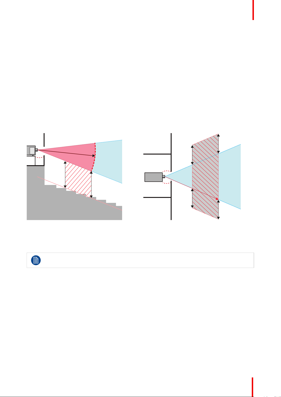
Image 1-1
A Side View
B Top View
RA Restricted Area
PR Projector
TH Theater
RZ Restriction Zone in the theater
SH Separation Height
SWSeparation Width
Regarding the SH Distance: For Cinema applications, the distance must be >2m. For Concert
applications, the distance must be >3m.
Based on national requirements, no person is allowed to enter the projected beam within the zone between
the projection lens and the related hazard distance (HD). This shall be physically impossible by creating
sufficient separation height or by placing barriers. The minimum separation height takes into account the
surface upon which persons other than operator, performers or employees are permitted to stand.
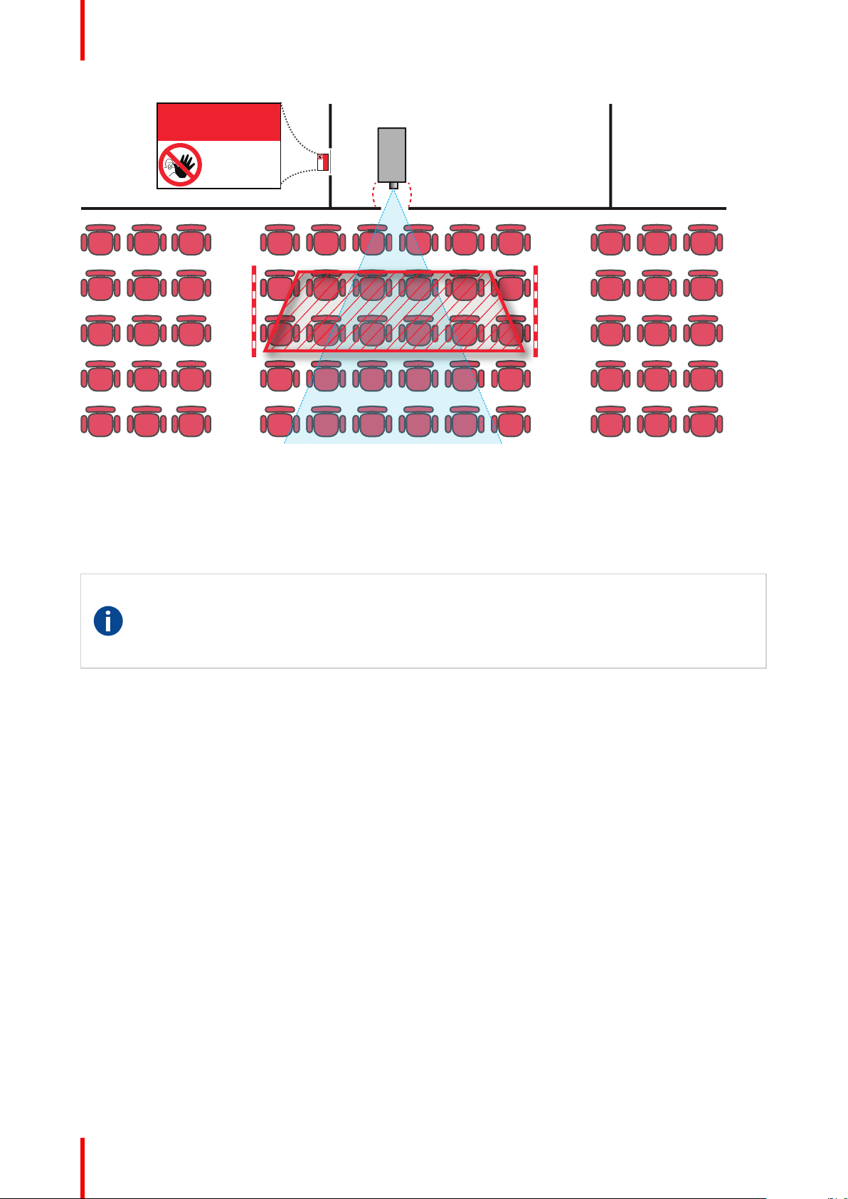
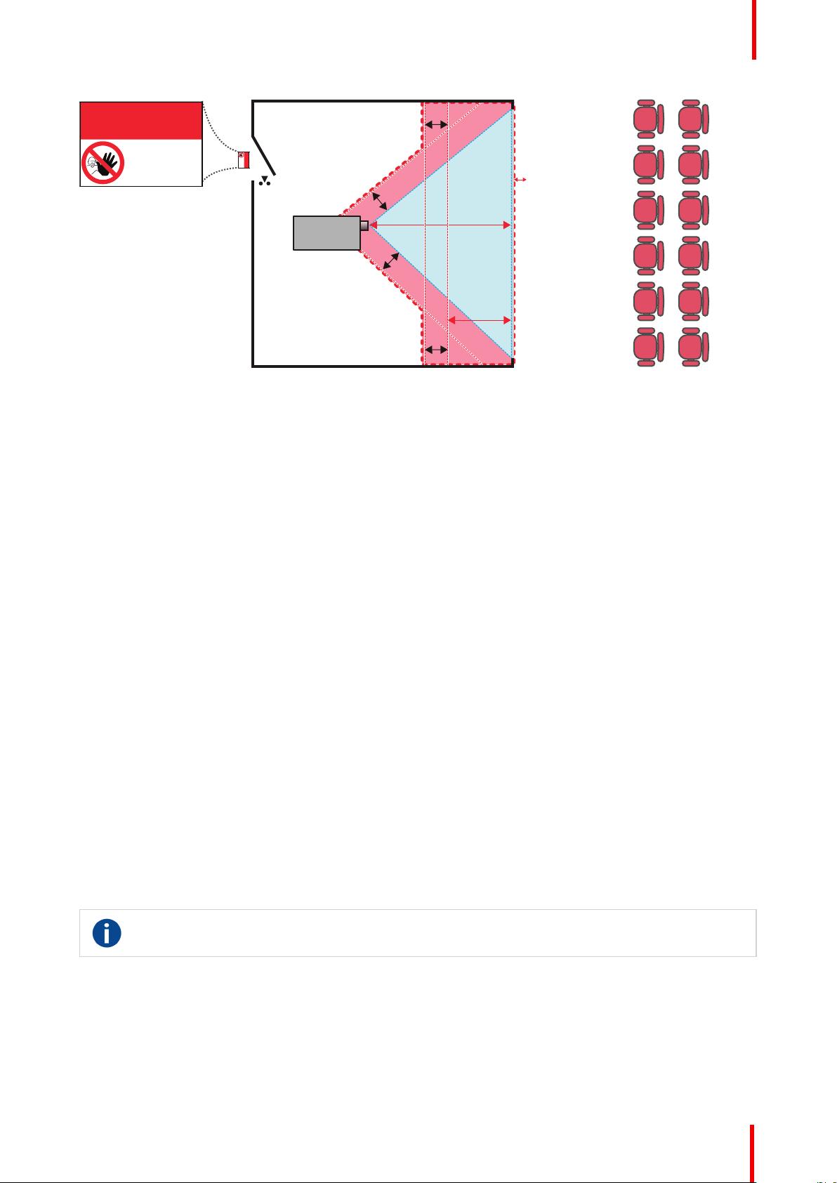
On image 1-2 a typical setup is displayed. It must be verified if these minimum requirements are met. If
required a restricted zone (RZ) in the theater must be established. This can be done by using physical barrier,
like a red rope as illustrated in image 1-2.
The restricted area sticker can be replaced by a sticker with only the symbol.
601–426-03 F70 Series 15
Page 16
PR
RESTRICTED
AREA
RESTRICTED
AREA
Safety
Image 1-2
1.5 Hazard Distance for fully closed projection system
HD
Hazard Distance (HD) is the distance measured from the projection lens at which the intensity or the
energy per surface unit becomes lower than the applicable exposure limit on the cornea or on the
skin. The light beam is considered (to be) unsafe for exposure if the distance from a person to the
light source is less than the HD.
Restriction Zone RZ Based on the HD
The projector is also suitable for rear projection applications; projecting a beam onto a defuse coated
projection screen. As displayed in image 1-3 two areas should be considered: the restricted enclosed
projection area (RA) and the observation area (TH).
601–426-03 F70 Series16
Page 17
RA TH
sw
PD
HD
DIFFUSE
sw
RZ
sw
sw
PR
HD
REFLECTION
RESTRICTED
AREA
RESTRICTED
AREA
Image 1-3
Safety
RA Restricted Access location (Enclosed projection
area)
PR Projector.
RZ Restriction Zone
PD Projection Distan
SWSeparation Width. Must be minimum 1 meter.
TH Theater (observation area).
Restriction zone (RZ) based on the HD continued.
For this type of setup 3 different HD shall be considered:
• HD as discussed in "High Brightness precautions: Hazard Distance (HD)", page 6 , relevant for intrabeam
exposure.
• HDreflection : the distance that has to be kept restrictive related to the reflected light from the rear
projection screen.
• HDdiffuse : the relevant distance to be considered while observing the defuse surface of the rear projection
screen.
As described in "High Brightness precautions: Hazard Distance (HD)", page 6 , it is mandatory to create a
restricted zone within the beam areas closer than any NOHD. In the enclosed projection area the combination
of two restricted zones are relevant: The restricted zone of the projected beam toward the screen; taking into
account 1 meter Separation Width (SW) from the beam onward. Combined with the restricted zone related to
the rear reflection from the screen (HDreflection); also taking into account a 1 meter lateral separation.
The HDreflection distance equals 25% of the difference between the determined HD distance and the
projection distance to the rear projection screen. To determine the HD distance for the used lens and projector
model see graphs in chapter "HD in function of the lens Throw Ratio (TR)", page 8 .
HDreflection = 25% (HD – PD)
The light emitted from the screen within the observation shall never exceed the RG2 exposure limit,
determined at 10 cm. The HDdiffuse can be neglected if the measured light at the screen surface is below
5000 cd/m² or 15000 LUX.
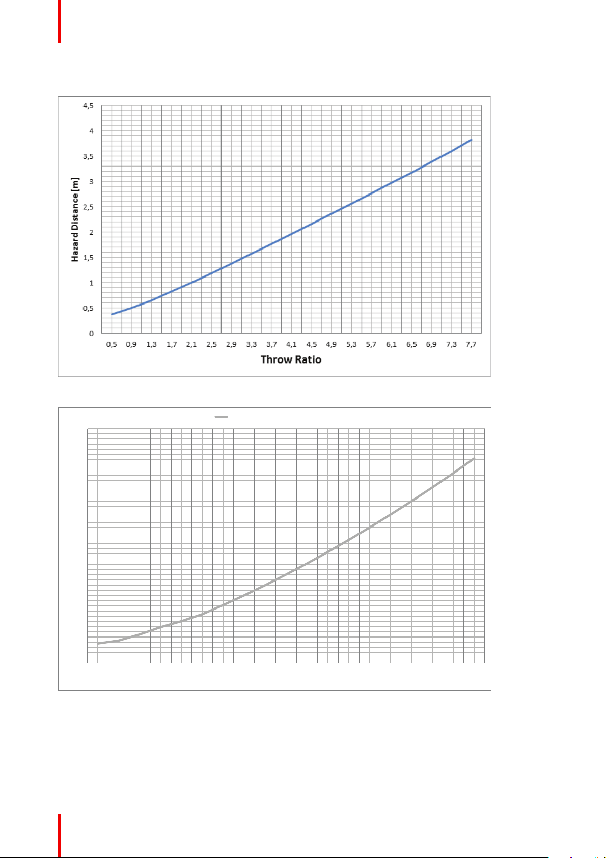
1.6 HD in function of the lens Throw Ratio (TR)
TR (Throw Ratio)
The ratio of the distance to the screen (throw) to the screen width.
601–426-03 F70 Series 17
Page 18
0
0,2
0,4
0,6
0,8
1
1,2
1,4
1,6
1,8
0,5 0,9 1,3 1,7 2,0 2,3 2,7 3,1 3,5 3,9 4,3 4,7 5,1 5,5 5,9 6,3 6,7 7,1 7,5
Hazard Distance [m]
Throw Ra!o
Hazard Distance Thermal Acidental Exposure
Safety
HD versus Throw Ratio
Image 1-4: Hazard Distance in meters versus Throw ratio of
the lens for the F90 projectors
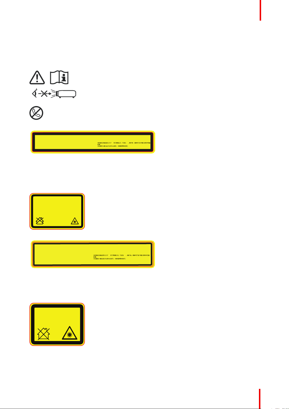
Image 1-5: Hazard Distance in meters versus Throw ratio of
the lens for the F70 projectors
Graphs shows Hazard Distance in meters versus Throw ratio of the lens
601–426-03 F70 Series18
Page 19
1.7 Safety symbols
For North America, this projector may become RG3 when an interchangeable lens with throw ratio greater than
2.33 is installed. Refer to the manual for the lens list and hazard distance before operation. Such combinations of
projector and lens are intended for professional use only, and are not intended for consumer use.
This projector may become RG3 when an interchangeable lens with throw ratio greater than 3.15 is
installed. Refer to the manual for the lens list and hazard distance before operation. Such combinations
of projector and lens are intended for professional use only, and are not intended for consumer use.
Ce projecteur peut devenir un projecteur RG3 en cas d'installation d'un objectif interchangeable
dont le rapport de projection est supérieur à 3,15. Veuillez vous reporter au manuel pour en savoir
plus sur la liste des objectifs et la distance de sécurité avant toute utilisation. De telles combinaisons
entre projecteur et objectif sont conçues pour des applications professionnelles uniquement et pas
pour des applications grand public.
3.15 RG3
THIS PRODUCT IS IN CONFORMITY
WITH PERFORMANCE STANDARDS
FOR LASER PRODUCTS UNDER 21
CFR 1040, EXCEPT WITH RESPECT TO
THOSE CHARACTERISTICS
AUTHORIZED BY VARIANCE NUMBER
2016-V-0144 EFFECTIVE
MARCH 6, 2017.
For North America, this projector may become RG3 when an interchangeable lens with throw ratio
greater than 2.5 is installed. Refer to the manual for the lens list and hazard distance before operation.
Such combinations of projector and lens are intended for professional use only, and are not intended
for consumer use.
This projector may become RG3 when an interchangeable lens with throw ratio greater than 4.7 is
installed. Refer to the manual for the lens list and hazard distance before operation. Such
combinations of projector and lens are intended for professional use only, and are not intended
for consumer use.
Ce projecteur peut devenir un projecteur RG3 en cas d'installation d'un objectif interchangeable
dont le r
apport de projection est supérieur à 4.7. Veuillez vous reporter au manuel pour en savoir
plus sur la liste des obje
ctifs et la distance de sécurité avant toute utilisation. De telles combinaisons
entre projecteur et objectif sont conçues pour des applications professionnelles uniquement et pas
pour des applications grand public.
4.7 RG3
THIS PRODUCT IS IN CONFORMITY WITH
PERFORMANCE STANDARDS FOR LASER
PRODUCTS UNDER 21 CFR 1040, EXCEPT
WITH RESPECT TO THOSE CHARACTERISTICS
AUTHORIZED BY VARIANCE NUMBER
2016-V-0144 EFFECTIVE MARCH 6, 2017.
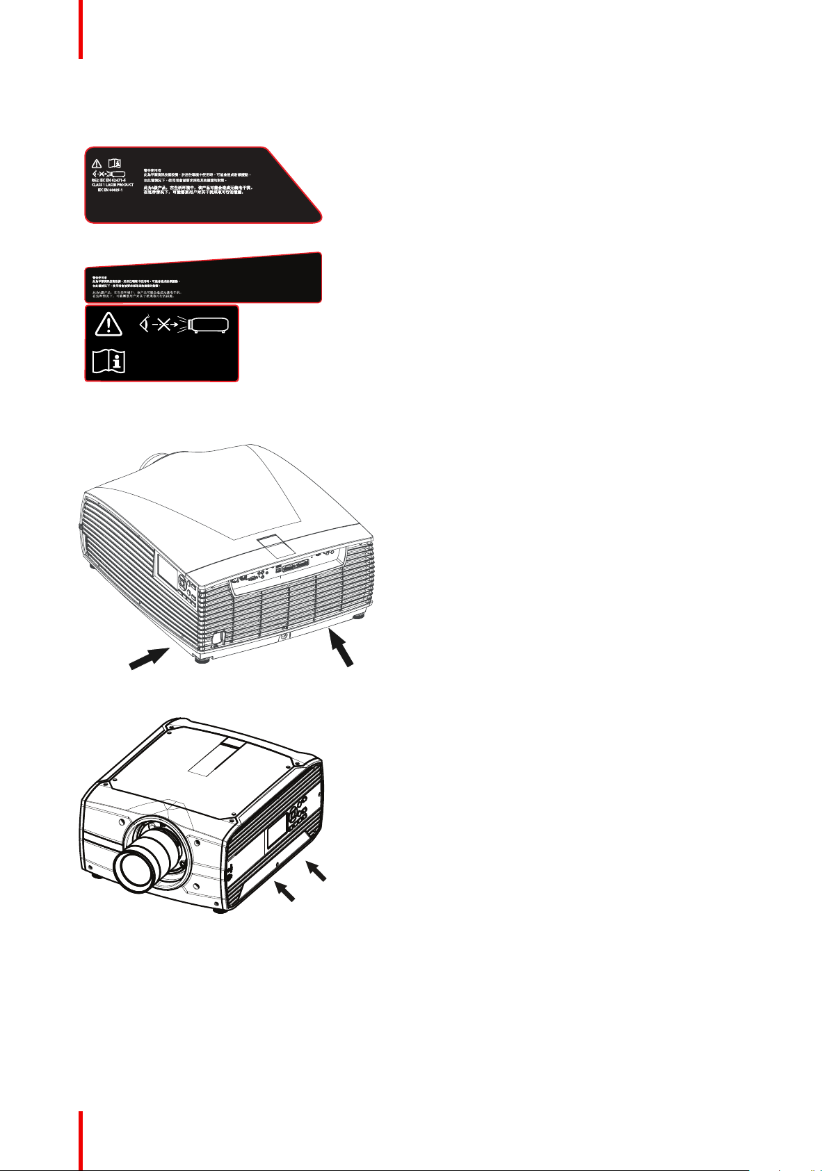
Description of safety symbols used in product documentation or on product.
Image Description
Refer to user manual for further
information!
Caution! Do not stare into beam,
RG2 product.
No telephone! Do not connect to
telephone lines.
Safety
For F90 series: Warning Label
For F90 series: FDA Label
For F70 Series: Warning label
Caution! For North America: With
interchangeable lens with throw ratio
greater than 2.33, consider hazard
distance and installation
requirements for RG3 product. Refer
User Manual.
Caution! With Interchangeable lens
with throw ratio greater then 3.15,
consider hazard distance and
installation requirements for RG3
product. Refer User manual.
Caution! For North America: With
interchangeable lens with throw ratio
greater than 2.5, consider hazard
distance and installation
requirements for RG3 product. Refer
User Manual
Caution! With Interchangeable lens
with throw ratio greater then 4.7,
consider hazard distance and
installation requirements for RG3
product. Refer User manual.
For F70 Series: FDA Label
601–426-03 F70 Series 19
Page 20
This is a class A product. In a domestic environment this product
may cause radio Interference in which case the user may be
required
to take adequate measures.
This device complies with part 15 of the FCC Rules, Operation is subject to the following
conditions: (1) This device may not cause harmful interference, and (2) this device must
accept any interference received, including interference that may cause undesired operation.
This C
lass A digital apparatus complies with Canadian ICES-003, / Cet appareil numerique
de Ia
classe est conforme à Ia norme NMB-003 du Canada.
EMC:
FC
C:
CANADA:
IEC EN 60825-1
CL
ASS 1 LASER PRODUCT
RG2 IEC EN 62471-5
This Class A digital apparatus complies with Canadian ICES-003, / Cet
appareil numerique de Ia classe est conforme à Ia norme NMB-003 du
Canada.
CANADA:
This device complies with part 15 of the FCC Rules, Operation is subject to the following
conditions: (1) This device may not cause harmful interference, and (2) this device must
accept any interference received, including interference that may cause undesired operation.
FCC:
This is a class A product. In a domestic environment this product may
cause radio Interference in which case the user may be required
to take adequate measures.
EMC:
RG2 IEC EN 62471-5
IEC EN 60825-1
CLASS 1 LASER PRODUCT
8
9
EMC Label Warning Label
Warning and EMC labels
Safety
Image Description
F70 EMC Label
F90 EMC Label
Location of Safety Label
Image 1-6: F90 Projector
Image 1-7: F70 Projector
Disposal Information
Waste Electrical and Electronic Equipment
601–426-03 F70 Series20
Page 21
Safety
This symbol on the product indicates that, under the European Directive (EU) 2015/863 governing waste
from electrical and electronic equipment, this product must not be disposed of with other municipal waste.
Please dispose of your waste equipment by handing it over to a designated collection point for the recycling of
waste electrical and electronic equipment. To prevent possible harm to the environment or human health from
uncontrolled waste disposal, please separate these items from other types of waste and recycle them
responsibly to promote the sustainable reuse of material resources.
For more information about recycling of this product, please contact your local city office or your municipal
waste disposal service.
For details, please visit the Barco website at: http://www.barco.com/en/AboutBarco/weee
WEEE Information
This product conforms to all requirements of the EU Directive on waste electrical and electronic equipment
(WEEE). This product shall be recycled properly. It can be disassembled to facilitate proper recycling of it’s
individual parts.
Consult your dealer or relevant public authority regarding drop-off points for collection of WEEE. For details,
please visit the Barco website at: http://www.barco.com/en/ AboutBarco/weee.
CAUTION: This product contains chemicals, including lead, known to the State of California to
cause birth defects or other reproductive harm. Recycle properly, do not dispose of in ordinary
waste!
Turkey RoHS compliance
Türkiye Cumhuriyeti: AEEE Yönetmeliğine Uygundur.
[Republic of Turkey: In conformity with the WEEE Regulation]
1.8 RoHS compliance
中国大陆 RoHS (Chinese Mainland RoHS)
根据中国大陆《电器电子产品有害物质限制使用管理办法》(也称为中国大陆RoHS), 以下部分列出了
Barco产品中可能包含的有毒和/或有害物质的名称和含量。中国大陆RoHS指令包含在中国信息产业部MCV标
准:“电子信息产品中有毒物质的限量要求”中。
According to the “Management Methods for the Restriction of the Use of Hazardous Substances in Electrical
and Electronic Products” (Also called RoHS of Chinese Mainland), the table below lists the names and
contents of toxic and/or hazardous substances that Barco’s product may contain. The RoHS of Chinese
Mainland is included in the MCV standard of the Ministry of Information Industry of China, in the section “Limit
Requirements of toxic substances in Electronic Information Products”.
601–426-03 F70 Series 21
Page 22
Component Name
Hazardous Substances or Elements
(Pb)
(Hg)
(Cd)
(Cr6+)
(PBB)
(PBDE)
X
O
X O O
O
Printed Circuit Assemblies
X O O O O
O
External Cables
X O O O O
O
Internal wiring
X O O O O
O
Lensholder
X O O O O
O
Laser
O O O O O
O
Chassis
O O O O O
O
Enclosure
X O O O O
O
Nuts, bolts, screws, washers. Fasteners
X O O O O
O
Power Supply Unit
O O O O O
O
Heatsinks
X O O O O
O
Fan
O O O O O
O
Plastic Enclosure
O O O O O
O
Enclosure
O O O O O
O
Batteries
O O O O O
O
Paper Manuals
O O O O O
O
Installation kit
X O O O O
O
Remote control
SJ/T 11364
This table is prepared in accordance with the provisions of SJ/T 11364.
O: GB/T 26572
O: Indicates that this toxic or hazardous substance contained in all of the homogeneous materials for this part is below the
limit requirement in GB/T 26572
X: GB/T 26572
X: Indicates that this toxic or hazardous substance contained in at least one of the homogeneous materials used forth is part
is above the limit requirement in GB/T 26572.
Safety
Image 1-8
在中国大陆销售的相应电子信息产品(EIP)都必须遵照中国大陆《电子电气产品有害物质限制使用标识要
求》标准贴上环保使用期限(EFUP)标签。Barco产品所采用的EFUP标签(请参阅实例,徽标内部的编号使
用于指定产品)基于中国大陆的《电子信息产品环保使用期限通则》标准。
All Electronic Information Products (EIP) that are sold within Chinese Mainland must comply with the “Marking
for the restriction of the use of hazardous substances in electrical and electronic product” of Chinese
Mainland, marked with the Environmental Friendly Use Period (EFUP) logo. The number inside the EFUP
601–426-03 F70 Series22
Page 23

10
Safety
logo that Barco uses (please refer to the photo) is based on the “General guidelines of environment-friendly
use period of electronic information products” of Chinese Mainland.
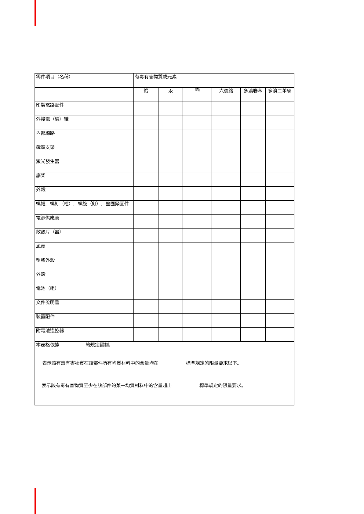
1.9 Taiwan RoHS compliance
零件项目(名称)
Component Name
印制电路配件
Printed Circuit Assemblies
外接电(线)缆
External Cables
內部线路
Internal wiring
镜头支架
Lensholder
激光发生器
Laser
底架
Chassis
外壳
Enclosure
螺帽,螺钉(栓),螺旋( 钉),垫圈, 紧固
件
Nuts, bolts, screws, washers,
Fasteners
电源供应器
Power Supply Unit
有毒有害物质或元素
Hazardous Substances or Elements
铅
(Pb)
X O X O O O
X O O O O O
X O O O O O
X O O O O O
X O O O O O
O O O O O O
O O O O O O
X O O O O O
X O O O O O
汞
(Hg)
镉
(Cd)
六价铬
(Cr6+)
多溴联苯
(PBB)
多溴二苯
醚
(PBDE)
散热片(器)
Heatsinks
风扇
Fan
塑胶外壳
Plastic Enclosure
外壳
Enclosure
电池(组)
Batteries
文件说明书
O O O O O O
X O O O O O
O O O O O O
O O O O O O
O O O O O O
O O O O O O
601–426-03 F70 Series 23
Page 24

Safety
零件项目(名称)
Component Name
Paper Manuals
装置配件
Installation kit
附電池遙控器
Remote control
本表格依据SJ/T 11364的规定编制
This table is prepared in accordance with the provisions of SJ/T 11364.
O: 表示该有毒有害物质在该部件所有均质材料中的含量均在 GB/T 26572 标准规定的限量要求以下.
O: Indicates that this toxic or hazardous substance contained in all of the homogeneous materials for this
part is below the limit requirement in GB/T 26572.
X: 表示该有毒有害物质至少在该部件的某一均质材料中的含量超出 GB/T 26572 标准规定的限量要求.
X: Indicates that this toxic or hazardous substance contained in at least one of the homogeneous materials
used for this part is above the limit requirement in GB/T 26572.
有毒有害物质或元素
Hazardous Substances or Elements
铅
(Pb)
O O O O O O
X O O O O O
汞
(Hg)
镉
(Cd)
六价铬
(Cr6+)
多溴联苯
(PBB)
多溴二苯
醚
(PBDE)
1.10 Contact information
Barco contact information
Registered office address: President Kennedypark 35, 8500 Kortrijk, Belgium
Contact address: Beneluxpark 21, 8500 Kortrijk, Belgium
Contact address (for Taiwan) :
Barco ltd.., 33F., No. 16. Xinzhan Rd., Banqiao Dist.,, New Taipei City 220, Taiwan
Tel: +886-2-7715-0099, Fax: +886-2-7715-0097
E-mail: service.taiwan@barco.com
Importers contact information
To find your local importer, contact Barco directly or one of Barco's regional offices via the contact information
given on Barco's web site, www.barco.com.
Contact information Norway factory
Barco Fredrikstad as
Habornveien 53, N1630 Gamle Fredrikstad, Norway
Phone: +476930 4550
Support:Support.fre@barco.com
601–426-03 F70 Series24
Page 25

Safety
1.11 Product Info
Product info
Image 1-9
product name 產品名稱:
projector 投影機
model 型號: GP6 / GP7
1.12 Statement
EN55032/CISPR32 Class A MME (MultiMedia Equipment)
Warning : This equipment is compliant with Class A of CISPR 32. In a residential environment this equipment
may cause radio interference.
Class A ITE (Information Technology Equipment)
Warning : This is a class A product. In a domestic environment this product may cause radio interference in
which case the user may be required to take adequate measures.
警告使用者: 此為甲類資訊技術設備,於居住環境中使用時,可能會造成射頻擾動,在此種情況下,使用者會
被要求採取某些適當的對策。
601–426-03 F70 Series 25
Page 26

Safety
601–426-03 F70 Series26
Page 27

Getting to know the projector.
Overview
•
Main Components
• Service and Maintenance
• LED Status Light
• Power on / Standby button backlight indications
• LCD panel
• Local keypad
• Remote Control
• Projector Address
• Connector panel
• Color Wheels
• Optional Accessories
2
601–426-03 F70 Series
27
Page 28
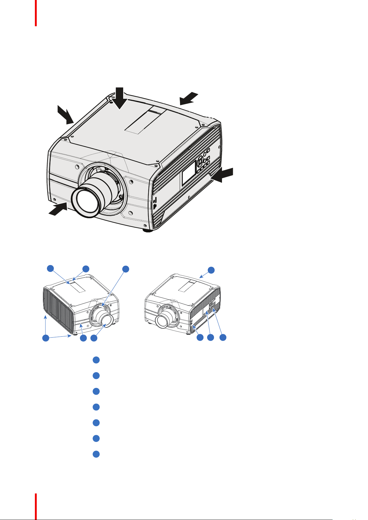
Left
Right
Back
Front
Top
76
35
1
5
2
4
9
8
1
1
1
2
1
3
1
4
1
5
1
6
1
7
Getting to know the projector.
2.1 Main Components
Naming Conventions
Image 2-1
Projector Items Overview
Image 2-2
LED Warning Indicator
Adjustable Feet
Lens
Lens Holder
IR Receiver. For receiving remote control signals
LCD Display
Keypad Panel. Used for local operation of the projector.
601–426-03 F70 Series28
Page 29

1
8
1
9
Getting to know the projector.
Connector Panel. Control and communication interfaces for the projector
Front USB and Triggerboard.
2.2 Service and Maintenance
General
The F70 series does not have any user serviceable parts.
All service tasks must only be carried out by the manufacturer, or a Barco authorized service personnel or
Barco technicians.
2.3 LED Status Light
About
The F70 Status Led is located on the rear top of the Projector
During normal operation, the LED is not illuminated. In the event of a critical error or high temperature, the
LED will illuminate red.
By critical error, the projector cannot be restarted until the projector is disconnected from the power supply and
then reconnected again. If the reason for the error persist, the projector will again go to critical error status.
By high temperature, the projector can be restarted when it has cooled down, and the temperature is back
within the normal operating limitations
2.4 Power on / Standby button backlight indications
Indicator
In addition to the LED indicator, the projector also displays status indications in the backlight of the Power /
Standby button.
The table below shows the details regarding this indications.
Operating Status
On (active) Blue
Wait on Blue flashing
Standby (off) White
Wait White short flashing
Overheating Red flashing
Configure/upgrade White fast flashing
Standby ECO White heartbeat
Indication Color / Behavior
2.5 LCD panel
About
The LCD panel (See chapter 2.6, Local Keypad) is located on the right side of the projector, and has two
modes of indication; Mirror of the OSD, or Information display.
Toggle between the two indications by using the Menu button on the keypad, or on the remote control
1.
601–426-03 F70 Series 29
Page 30
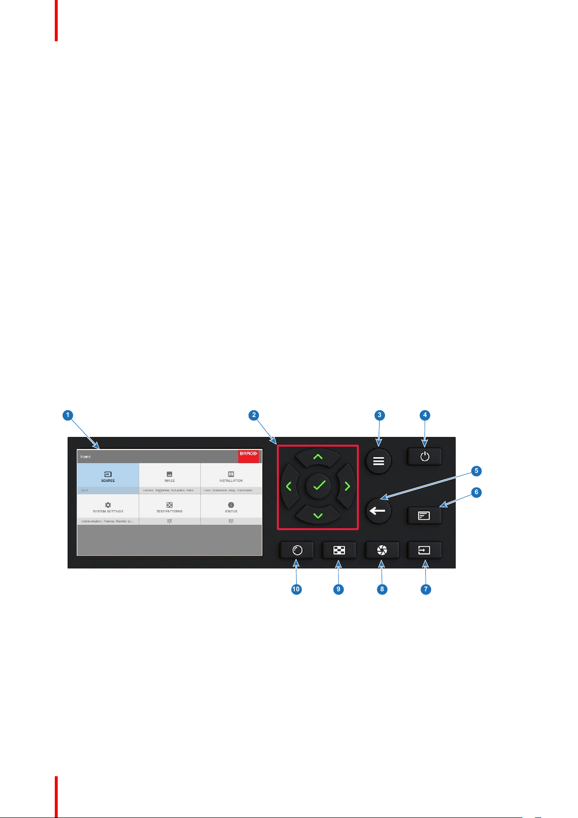
1
2
3 4
9 8
5
7
6
10
Getting to know the projector.
When mirroring the OSD, the LCD showing the menus and adjustment information.
2.
When in information mode, showing this Information regarding the status of the projector:
• Projector status
• Network address and status
• Active source
• Illumination Status
• Current firmware version
• Active functions (Enabled Functions).
• Display Info, including Transport delay
• Environment Info.
Use the navigation keys (arrows) to scroll the information menu.
When in information mode, press OK (confirm selection (✓)) to see notifications and warnings.
The LCD Display will fade out 15 seconds after the last key operation.
2.6 Local keypad
About
The Keypad gives direct access to several functions, in addition to access to the menu system. The keypad
and remote control functions are equal.
The keypad has a back light that can be switched on and off manually. The light turns off automatically after a
preset time.
The Standby key is equipped with white, blue and red backlight depending on the status of the projector. See
table in “Power on / Standby button backlight indications”, page 29 for info regarding this.
Image 2-3
Item
No.
Name
Description
1 LCD Display Shows Projector status and navigation menu.
2 Navigation keys Navigation arrows (up, down, left, right), confirm selection (✓)
3 Menu button Toggle between OSD / Information menu.
4 Standby Power on / standby
5 Back Undo action / back to previous screen.
601–426-03 F70 Series30
Page 31

1
2
Getting to know the projector.
Item
No.
6 OSD ON/OFF Deactivate the On Screen Display (OSD). Only critical warnings will be
7 Input Shortcut to input source menu on LCD. Use navigation keys to select and
8 Shutter Enable and disable the lens shutter function. This is not a mechanical shutter,
9 Test Patterns Shortcut to test pattern menu on LCD. Use navigation keys to select the desired
10 Lens Shortcut to lens function. A test pattern displays on the OSD. LCD screen
Name
displayed.
enable input.
but it toggles the laser source on and off. Backlight is red when the shutter are
enabled.
pattern.
displays the navigation keys to manage and confirm actions.
Description
2.7 Remote Control
2.7.1 Remote control, Battery installation
Where to find the batteries for the remote control ?
The batteries are not placed in the remote control unit to avoid control operation in its package, resulting in a
shorter battery life time. At delivery the batteries can be found in a separated bag attached to the remote
control unit. Before using your remote control, install the batteries first.
How to install
1. Push the battery cover tab with the fingernail a little backwards (1) and pull, at the same time, the cover
upwards (2).
Image 2-4
2. Insert the two AA size batteries, making sure the polarities match the + and - marks inside the battery
compartment.
Tip: Use alkaline batteries for optimum range and life time.
601–426-03 F70 Series 31
Page 32

+
-
-
+
+
-
-
+
1
2
Getting to know the projector.
Image 2-5
3. Insert (1) both lower tabs of the battery cover in the gaps at the bottom of the remote control, and press (2) the
cover until it clicks in place.
Image 2-6
When replacing batteries, the broadcast address of the RCU will be reset to its default value '0'.
CAUTION: Replace with the correct battery type. Use two AA size batteries. There is a risk of
explosion if the battery is replaced with an incorrect type.
CAUTION: Replace the battery as explained above. There is a risk of explosion if the battery is
incorrectly installed.
2.7.2 Remote control, protocol setup
About the used protocol
The protocol is the code send out by the remote control when a button is pressed. Depending on this code, the
projector can decode the signals. The remote control can be used with two different protocols, RC5 and NEC.
Depending on the projector to control the remote control can be switched between these protocols.
Which protocol to use
• The NEC protocol have to be used for Barco projectors based on the Pulse platform: Loki, Balder, F70,
F80, F90, HDX 4K, UDX, ...
• The RC5 protocol have to be use all other Barco projectors: HDX W, HDF W, HDQ 2K, ...
How to set
1. Remove the cover. For more info on how to remove, see “Remote control, Battery installation”, page 31.
2. Place the switch in the NEC position.
601–426-03 F70 Series32
Page 33

1
2
3
4
5
6
7
8
9
10
11
12
15
24
23
22
21
20
19
18
17
16
13
14
2625
1
14
2
15
3
16
4
17
5
18
6
19
7
20
8
21
9
22
10
23
11
24
12
25
13
26
Getting to know the projector.
Image 2-7
Remark with RC5 protocol
Not all buttons of the Pulse RCU are one-to-one compatible with the legacy Barco RCU. Button pairs
SHUTTER open/close and POWER on/off emit the same code (per pair) when in RC5 mode, because the
legacy RCU’s only had 1 button for Shutter and 1 button for Standby.
2.7.3 Functionality overview
Remote Control Unit buttons
Button pressed indicator.
Shutter Open.
Shutter Close.
Touch Panel On/Off.
(Not in use).
OSD On/Off.
Lens Zoom.
Lens Shift.
Menu Activation.
Menu Selection, OK
button.
Menu Navigation.
Input Selection.
Address button.
Numeric buttons.
Backspace (while
entering values)
XLR connector.
Decimal mark (while
entering values)
Macro button. (Not in
use)
Menu Back.
Default button. (Not in
use).
Lens Focus.
Real Color menu..
Test Patterns.
Power On.
Power Off.
Stereo Jack.
RCU On/Off.
The projector remote control is a full feature wireless remote control, powered by two (2) standard AA
batteries. The battery compartment is on the back side of the remote control.
The remote control is backlit for use in dark environments. It also has an Jack connector for wired connection
to the projector. When the wire is connected, the IR beam is switched off.
601–426-03 F70 Series 33
Page 34

1
Getting to know the projector.
2.7.4 Remote control, on/off button
Purpose of the remote control on/off button
The Pulse remote control unit has at the front side an on/off switch (reference 1 Image 2-8). Switching off the
remote control prevents that unwanted commands are send due to an accidental key press. Furthermore,
switching the RCU off will extend the battery life time of the remote control.
To activate the remote control press the on/off button.
To deactivate the remote control press the on/off button again.
Default when (re)placing batteries, is “ON”.
Image 2-8
2.7.5 Enable / Disable Remote Control
About
This function are for disabling the IR sensors for the remote control. Either front or rear, or both.
Image 2-9
• Select the menu path Home/System Settings/Communication/IR control
• Select which sensors to be disabled.
• Enter the Apply button to confirm the action
When all sensors are turned off, the projector will not receive any signals from the remote control.
To enable the sensors again, use the keypad on the projector.
2.7.6 Wired RC connection
About
The remote control can also be directly wired to the projector from the stereo jack connector on the remote,
(See “Functionality overview”, page 33 ), to the RC connector on the back panel of the projector.(See section
“Connector Panel”)
In this mode, the projector will not be affected by signals from other non-wired remote controls.
601–426-03 F70 Series34
Page 35

Getting to know the projector.
When using wired remote control, the broadcast address must be set to “Generic ID (0)”. See the menu in
“Enable / Disable Remote Control”, page 34.
It is not possible to program the remote control in wired mode. (Directly connected, no sense in programming).
2.8 Projector Address
Projector address
Address installed in the projector to be individually controlled.
Broadcast address
Projector will always execute the command coming from a RCU programmed with that broadcast
address.
2.8.1 Controlling the projector
Why a projector address?
As more than one projector can be installed in a room, each projector should be separately addressable with
an RCU or computer. Therefore each projector has its own address.
Set up an individual Projector Address
The set up of a projector address can be done via the software.
Projector controlling
When the address is set, the projector can be controlled now:
• with the RCU: only for addresses between 1 and 31.
Broadcast Address
Every projector has a broadcast (common) address '0' or '1'. The default address is '0'.
The choice between '0' and '1' can be selected in the GUI: “System Settings” → “Communication” →“IR Control
“.
Placing new batteries in the remote control or plugging the remote to a projector via a cable will
automatically reset the address back to its default value '0'.
2.9 Connector panel
General
The source input panel is located at the back of the projector. For source specifications, see table below.
Image 2-10
Name Pcs
DMX IN 1 DMX 512 input For Projector Control
DMX OUT 1 DMX 512 output For Projector Control
Description Purpose
601–426-03 F70 Series 35
Page 36

Getting to know the projector.
Name Pcs
RS-232 1 9–pin DB9 connector For Projector Control. Allows for wired remote
Sync 3 BNC Sync Port IN/OUT;
Trigger 3 (one in
front,
two on
rear
panel)
RC 1 Jack connector for wired
USB 3 USB 2.0 type A, 4 pin( 2x Rear
LAN 1 Standard RJ45 connector For Projector Control
DP 2 Standard display port For Projector Input
DL-DVI-D 2 Dual DVI-I 1.0 (DVI_D
Description Purpose
control and monitoring of many projector functions
used in installation environments
For Projector ControlThis is mainly used in multiple
Bidirectional mini-DIN (1x 3D
sync Out, and 2x Sync In/Out)
12VDC - 0,5A (6W) For Controlling Peripherals, like motorized
remote
and 1x Front)
Functionallity).
projector installations with requirement of
synchronization between the units
screens, curtains etc. Give 12V output when
projector are switched on. NOTE Disconnect the
projector power cable before connecting or
removing the trigger cable
For Projector Control
For Software upgrade
For Projector Input. These connectors can also be
used to form one uniform image by feeding half of
the image into each connector. HDCP compliant
for sources up 165 Mhz
HDMI 1 Standard HDMI 2.0 For Projector Input
HDBaseT 1 Standard RJ45 8P8C
Connector
SDI 2 SDI1 is Input, SDI 2 is pass
through. (out)
For Projector Control
For Projector Input
2.10 Color Wheels
About
The F70 Projector is delivered with a standard Color wheel, that is suitable for most applications.
Other colorwheels are available upon request.
Consult Barco sales office or a service partner in order to find the most suitable colorwheel for the specific
application.
2.11 Optional Accessories
Rigging Frame
Item Number
R9802224 F70/F90 Multifunctional Frame.
Item Description
The F70 Rigging frame is a rugged, easy to install frame, designed to streamline the process of installing one
or more projectors.
When installed i the frame, the projector:
• can be rotated around the x, y and z axis, in order to obtain a seamless adjustment in applications using
multiple projectors.
• Can be installed from a truss or a pedestal.
• Can be easily stacked one on top of another, for instance a dual or multichannel installations.
601–426-03 F70 Series36
Page 37

Flight Case
F70 use the same Flight case as the F90 series projectors.
Getting to know the projector.
Item Number
Item Description
R9801195 F90 flight case.
Image 2-11
The F70 Flight Case is a custom designed container, that is suitable for shipping the projector, including flight
frame, signal and power cords and up to two lenses.
The case is fully-lined to protect the projector and lenses during transit and storage.
601–426-03 F70 Series 37
Page 38

Getting to know the projector.
601–426-03 F70 Series38
Page 39

Lenses 3
About
Overview
•
Approved Lenses
• Lens range
• Replace a lens
• Lens shift
• Adjust zoom and focus
• Adjust Iris
601–426-03 F70 Series
39
Page 40

Lenses
3.1 Approved Lenses
Approved Lenses
Partnumber
R9801214 FLD 1.6 - 2.32 : 1 (EN11) approved approved
R9801218 FLD 0.74 : 1 (EN12) approved approved
R9801228 FLD 1.24 - 1.6 : 1 (EN13) approved approved
R9801209 FLD 2.37 - 3.79 : 1 (EN14) approved – professional
R9801225 FLD 1:16 : 1 (EN15) approved approved
R9801249 FLD 3.8 - 6.5 : 1 (EN16) approved – professional
R9801216 FLD+ 1.7 - 2.5 : 1 (EN41) approved approved
R9801226 FLD+ 0.8 : 1 (EN42) approved approved
R9801230 FLD+ 1.2 - 1.7 : 1 (EN43) approved approved
R9801211 FLD+ 2.5 - 4.6 : 1 (EN44) approved – professional
R9801220 FLD+ Long Focus 0.8 -
R9801221 FLD+ Short Focus 0.8 -
R9801295 FLD+ 0.65 : 1 (EN47) approved approved
PN_EN58 FLD+ 0.28 : 1 (EN58) approved approved
This projector may become Risk Group 3 (RG3) when an interchangeable lens with throw ratio greater than
4.7 is installed. For Northern America, installation requirements according to Risk group 3 (RG3) must be
followed when interchangeable lens with throw ratio greater than 2.5 is installed.
Refer to the manual chapter 1.7 for the throw ratio versus hazard distance before operation.
Description
1.21 : 1 (EN45)
1.21 : 1 (EN46)
For North Amrica Outside North america
approved – professional
use only
use only
use only
approved approved
approved approved
use only
approved – professional
use only
approved – professional
use only
3.2 Lens range
CAUTION: Always remove the lens from the lens holder before moving or transporting the
projector. Failure to do this may cause damage to the lens holder and prism.
Available lenses — WUXGA
The FLD lens range is custom-engineered for WUXGA and 1080 projectors.
The electrical connection to the lens motors is via a spring probe contact (pogo) pin array on the bayonet
mount.
The projector will automatically detect and identify the lens when it is installed. Automatic detection is not
available for 3rd party lenses.
601–426-03 F70 Series40
Page 41

EN11 EN12 EN13 EN14 EN15 EN16 EN33
Image 3-1
Lenses
Name
FLD Lens 1.6 - 2.32 :
1 (EN11)
FLD Lens 0.74 : 1
(EN12)
FLD Lens 1.24 - 1.6 :
1 (EN13)
FLD Lens 2.37 - 3.79
: 1 (EN14)
FLD Lens 1.16:1
(EN15)
FLD Lens 3.80 - 6.50
: 1 (EN16)
Name
FLD Lens 1.6 - 2.32 :
1 (EN11)
FLD Lens 0.74 : 1
(EN12)
Description
1.6-2.32 : 1 (WUXGA) R9801214 2.2 kg
0.74:1 (WUXGA) R9801218 1.9 kg
1.24 - 1.6 : 1 (WUXGA) R9801228 2.6 kg
2.37 - 3.79 : 1 (WUXGA) R9801209 2.5 kg
1.16 : 1 (WUXGA) R9801225 2.4 kg
3.8 - 6.5 : 1 (WUXGA) R9801249 2.5 kg
Working F#
2.1-2.52 Yes 2.1-6.5 1.45 33.2-48.1 2.0-15
2.1 Yes 2.1-6.5 - 16.35 0.5-5
Iris / Iris F# Zoom Ratio
Part number
Focal Length
(mm)
Weight
Focus Range
(m)
FLD Lens 1.24 - 1.6 :
1 (EN13)
FLD Lens 2.37 - 3.79
: 1 (EN14)
FLD Lens 1.16:1
(EN15)
FLD Lens 3.80 - 6.50
: 1 (EN16)
2.1-2.22 Yes 2.1-6.5 1.3 25.59-33.24 1.0-15
2.1-2.72 Yes 2.1-6.5 1.6 49.1-78.6 3.0-30
2.1 Yes 2.1-6.5 - 23.98 1.5-15
2.1-2.66 Yes 2.1-6.5 1.74 78.3-136.2 4.0-40
Available lenses — 4K, WUXGA, WQXGA
The FLD+ (EN4X) lens range is custom-engineered for WQXGA projectors.
The electrical connection to the lens motors is via a spring probe contact (pogo) pin array on the bayonet
mount. The projector will automatically detect and identify the lens when it is installed. Automatic detection is
not available for 3rd party lenses.
601–426-03 F70 Series 41
Page 42

EN41
EN42 EN43 EN44 EN45 EN46
Lenses
Image 3-2
Name
FLD+ Lens 1.7 - 2.5 : 1
(EN41)
FLD+ NV Lens 1.7 - 2.5 : 1
(NV41)
FLD+ Lens 0.8 : 1 (EN42) 0.75 : 1 (WUXGA) / 0.8 : 1
FLD+ Lens 1.2 - 1.7 : 1
(EN43)
FLD+ NV Lens 1.2 - 1.7 : 1
(NV43)
FLD+ Lens 2.5 - 4.6 : 1
(EN44)
FLD+ Lens 0.75 - 1.13 : 1
(EN45)
FLD+ Lens 0.75 - 1.13 : 1
(EN46)
FLD+ NV Lens 0.8 - 1.21 : 1
(NV46)
Description
1.58 - 2.33 : 1 (WUXGA) / 1.7 - 2.5
: 1 (WQXGA)
IR Optimized, 1.58 - 2.33 : 1
(WUXGA) / 1.7 - 2.5 : 1 (WQXGA)
(WQXGA)
1.12 - 1.58 : 1 (WUXGA) / 1.2 - 1.7
: 1 (WQXGA)
IR Optimized, 1.12 - 1.58 : 1
(WUXGA) / 1.2 - 1.7 : 1 (WQXGA)
2.33 - 4.3 : 1 (WUXGA) / 2.5 - 4.6 :
1 (WQXGA)
0.75 - 1.13 : 1 (WUXGA) / 0.8 -
1.21 : 1 (WQXGA)
0.75 - 1.13 : 1 (WUXGA) / 0.8 -
1.21 : 1 (WQXGA)
IR Optimized, 0.75 - 1.13 : 1
(WUXGA) / 0.8 - 1.21 : 1
(WQXGA)
Part number
R9801216 2.54 kg
R9801216 2.54 kg
R9801226 2.7 kg
R9801230 2.84 kg
R9801286 2.84 kg
R9801211 3.08 kg
R9801220 3.04 kg
R9801221 3.14 kg
R9801287 3.14 kg
Weight
FLD+ Lens 0.65 : 1 (EN47) 0.61 : 1 (WUXGA) / 0.65 : 1
(WQXGA)
Name
FLD+ Lens 1.7
- 2.5 : 1 (EN41)
FLD+ NV Lens
1.7 - 2.5 : 1
(NV41)
FLD+ Lens 0.8
: 1 (EN42)
FLD+ Lens 1.2
- 1.7 : 1 (EN43)
FLD+ NV Lens
1.2 - 1.7 : 1
(NV43)
601–426-03 F70 Series42
Working F#
2.1-2.5 Yes 2.1-6.5 1.47 33.70-49.54 1.5 - 15
2.1-2.5 Yes 2.1-6.5 1.47 33.70-49.54 1.5 - 15
2.1 Yes 2.1-6.5 - 16.12 0.7 - 7
2.4-2.7 Yes 2.4-6.5 1.42 23.95-34.02 1.5 - 15
2.4-2.7 Yes 2.4-6.5 1.42 23.95-34.02 1.5 - 15
Iris / Iris F# Zoom Ratio
R9801295 5.4 kg
Focal Length
(mm)
Focus Range
(m)
Page 43

Lenses
Name
FLD+ Lens 2.5
- 4.6 : 1 (EN44)
FLD+ Lens
0.75 - 1.13 : 1
(EN45)
FLD+ Lens
0.75 - 1.13 : 1
(EN46)
FLD+ NV Lens
0.8 - 1.21 : 1
(NV46)
FLD+ Lens
0.65 : 1 (EN47)
Working F#
2.1-2.93 Yes 2.1-6.5 1.85 49.52-91.60 2.5-25
2.4-3.29 Yes 2.4-6.5 1.51 15.85-23.93 5.0 - 30
2.4-3.29 Yes 2.4-6.5 1.51 15.98-23.99 0.7 - 7
2.4-3.29 Yes 2.4-6.5 1.51 15.98-23.99 0.7 - 7
2.1 Yes 2.1-6.0 - 12.6 0.5 - 4.0
Iris / Iris F# Zoom Ratio
Focal Length
(mm)
Focus Range
(m)
3.3 Replace a lens
Lens lever
The F70 lens mount and lens lever is designed to prevent damage to the lens board while providing an easy
and stable lens change procedure.
The lens lever, located at the bottom of the lens mount, slides between two positions, far left (default position
— unlocked) and far right (locked).
Always activate the projector shutter before attempting to remove or install a lens.
To do this, press the shutter button on the keypad, or shutter Close on the remote, to activate the
shutter. The keypad button will illuminate red when the shutter is activated.
Press the shutter button again, or shutter Open on the remote, to deactivate the shutter and
resume normal operation. The keypad button will illuminate white when the shutter is deactivated.
Image 3-3
601–426-03 F70 Series 43
Page 44

Lenses
Install a lens
1. Verify that the projector shutter is activated (shutter is activated when the shutter icon on the projector keypad
is red).
2. Verify that the lens release lever is in its default position at the far left of the slide, as illustrated.
3. Remove the protective cap at the lens bayonet end
4. Align the lens so that the red marking on the bayonet is facing upwards.
5. Position the lens bayonet into the projector lens mount and support in place with one hand.
6. Slide the lens lever to the far right.
7. Verify that the lens is firmly in place before removing your hand from the lens.
Image 3-4
Remove a lens
1. Support the lens with one hand.
2. Use the other hand to slide the lens release lever to the far left position.
3. Pull the lens straight out of the projector lens mount.
4. Replace with another lens, or install the projector lens cap.
Image 3-5
3.4 Lens shift
General
Use the Remote control or the keypad on the Projector to adjust the lens shift mechanism.
The lenses can be shifted vertically and horizontally to facilitate precise image positioning in single and
multiple projector systems. The projector allows for horizontal and vertical shift in both directions. Always
place the projector perpendicular to the screen, and use the lens shift to align the picture.
If not possible to align the projector perpendicular to the screen, due to environmemt of other, see chapter
“Warp – 4 Corners adjustment”, page 95
When EN 68 lens is installed in the projector, there are some limitations in the lens shift range, in
order to avoid damage to the lens.
This limitation will be identified as an reduction in the output light from the projector when the shift
position exceeds the defined range. The output light will then be reduced to 20% of max.
601–426-03 F70 Series44
Page 45

Lenses
3.5 Adjust zoom and focus
General
Zoom controls the size of the projected image.
Focus controls the sharpness of the projected image.
Lens zoom and focus adjustments are motorized. You can use the remote control, local keypad, OSD and/or
RS-232 commands to adjust the lens zoom and focus positions.
Not all lenses have zoom or iris control. The matrix below shows what controls are available per
lens.
E-
N11E-N12E-N13E-N14E-N15E-N16E-N33E-N41E-N42E-N43E-N44E-N45E-N46E-N47
Iris ✔ ✔ ✔ ✔ ✔ ✔ ✖ ✔ ✔ ✔ ✔ ✔ ✔ ✔
Zoom ✔ ✖ ✔ ✔ ✖ ✔ ✖ ✔ ✖ ✔ ✔ ✔ ✔ ✖
Focus ✔ ✔ ✔ ✔ ✔ ✔ ✔ ✔ ✔ ✔ ✔ ✔ ✔ ✔
For best results, lens adjustments should be done in the following order: zoom, focus and then iris (where
applicable).
3.6 Adjust Iris
General
Iris controls the contrast and focus depth of the image. Decreasing the iris will increase contrast and image
depth, at the same time as it decreases brightness.
Iris control is, as for the zoom and focus control, motorized, and is operated by the remote control or local
keypad.
Iris is only available for units with COLOR type colorwheel.
To enter Iris control, enter the menu Home/Installation/Lens /Iris
Image 3-6
Use the arrow keys to adjust Iris until preferred rendering is obtained.
601–426-03 F70 Series 45
Page 46

Lenses
601–426-03 F70 Series46
Page 47

Physical Installation 4
About
This chapter describes the physical conditions and procedures required when installing the F70 projector. It
also describes the outlines and some of the considerations that should be taken in to account when designing
and setting up the installation.
Each projector installation is unique, and as such the information in this chapter is only provided as a
guideline. Likewise, any images or graphical representations shown here are for illustrative purposes only.
If you require further information and assistance during the installation process, contact a qualified projection
technician or your local support office for advice.
Overview
•
Installation Process
• Installation conditions
• Initial inspection
• Positioning the projector
• Mounting the projector, general considerations
• Projector safe attachment points
• Throw distance
• Scheimpflug (Boresight) adjustment
• Scheimpflug adjustment procedure
601–426-03 F70 Series
47
Page 48

Physical Installation
4.1 Installation Process
Recommended Installation sequence
Item Procedure
1 Confirm that the installation area meets all
technical and environmental requirements
2 Decide where the projector will be
mounted
3 Unpack the projector and confirm that all
equipment is present and in good working
order
4 Mount the projector See “Mounting the projector, general
5 Install the projector lens See “Replace a lens”, page 43
6 Connect the source See “Projector source and control
7 Power up the projector See “Power up the projector”, page 63
8 Set up the image See “Image menu”, page 75
4.2 Installation conditions
Environmental Conditions
Barco projectors are manufactured according to specific design standards, which also include
environmental conditions. Failing to follow the terms and conditions outlined in this chapter can
result in loss of product warranty
Read more in chapter
See “Installation conditions”, page 48
See “Positioning the projector”, page 49
See “Initial inspection”, page 49
considerations”, page 50
connections”, page 60
The table below summarize the physical environments in which the projector may be safely operated or
stored.
Environment
0 -500m +10 to +45 °C 10 –80% RH –20 to +60 °C, 10 – 90 %
500 -1500m +10 to +40 °C 10 –80% RH –20 to +60 °C, 10 – 90 %
1500 - 3000m +10 to +35°C 10 –80% RH –20 to +60 °C, 10 – 90 %
Maximum Air Flow 900m
Ambient operating
temperature
3
/hour 10 –80% RH Not Applicable
Relative Humidity Storage condition
RH
RH
RH
Mains power requirement
Projector Power Requirement
F70 100 –240V. 50 –60 Hz.
To protect operating personnel, the National Electrical Manufacturers Association (NEMA) recommends that
the instrument panel and cabinet be grounded.
In no event shall this projector be operated without an adequate cabinet ground connection.
The AC supply must be installed by a qualified electrician in conformance to local codes. Hardware, wire sizes
and conduit types must comply with local codes.
Ventilation
The free space necessary between the air intake and exhaust are shown below.
601–426-03 F70 Series48
Page 49

1000 mm
500 mm
Physical Installation
Image 4-1
4.3 Initial inspection
General
Each projector is inspected and rigorously tested at our production facility to ensure that it is free from any
mechanical or electrical defects.
Upon receipt of the projector, we recommend that customers inspect the projector for any signs of damage
that may have occurred in transit. If damage is found, file a claim with the shipping carrier immediately. Notify
the Barco Sales and Service office, or your preferred Barco agent, of the damage as soon as possible.
Box Contents
Your projector box should contain the following:
• Projector unit
• Power cord (suitable for region)
• Quick start guide
• Safety manual
• Remote Control
The projector lens is delivered in a separate box.
4.4 Positioning the projector
CAUTION: The position and physical securing of the projector must be sufficient to prevent it from
accidental or involuntary movement. Proper securing of the projector is the responsibility of the
installer and user. The Projector are heavy, and can cause severe damage and injuries if falling.
601–426-03 F70 Series 49
Page 50

Physical Installation
General guidelines
Proper positioning of the projector lessens the overall picture setup time, and ensures a better image with
fewer artifacts.
Focus and sharpness of the image can be adversely affected if the lens axis is not fully
perpendicular to the projection surface.
Using extended cable lengths may result in reduced image quality as well as loss of control
information such as EDID (Extended Display Information Data).
The following guidelines can help you determine the best physical location for the projector.
• Only install the projector on a sturdy flat surface, or in an approved rigging frame.
• Do not install the projector in a thoroughfare or another area where it is at risk of being pushed or jostled.
• Allow sufficient free space around the projector for ventilation and exhaust, as described in section 4.2
• Use the throw ratio of the installed lens as a guideline for the projector’s physical distance from the screen.
• Wherever possible, the projector lens surface should be positioned so that it is perfectly perpendicular to
the center of the screen.
Use the projector offset (lens shift), rather than physical angling, to correct any off-center positioning.
• Minimize the source cable length as much as possible.
In general HDBaseT and 3G-SDI are long-haul interfaces and suitable for bespoke installations using
relatively long cables.
DP, HDMI and DVI are short-haul interfaces using pre-assembled cables with limited cable lengths.
• Limit the use of power cable extensions wherever possible. Where physical limitations necessitate their
use, make sure that the extension cord has adequate surge protection and meets all electrical
requirements of the connection.
• Keep the projector away from equipment that emits electromagnetic energy for example, motors,
transformers and elevators.
4.5 Mounting the projector, general considerations
Mounting safety
When mounting a projector in a rig, always use an interface plate (between the projector and the mount) that
has provision for a safety wire or another safety mechanism, to ensure that the projector does not fall down
should the interface plate come loose from the mount.
Always screw the interface plate securely to the projector body while the projector is on the ground (i.e. cannot
fall down). Then attach proper safety wire between the interface plate and the rig before mounting the
projector in the rig
Using 3rd party mounting equipment
The projector has features for mounting into various system environments using 3rd party mounts.
Four mounting inserts are located on the bottom of projector. The ceiling mount inserts have a pull-strength of
more than 4x the weight of the projector.
The feet can be removed and threads can be used for additional mounting points. See table below for
dimensions.
Parameter Value
Thread size M12
Length 18mm max 18mm max
Where possible, the projector lens must be positioned exactly perpendicular to the center of the
screen. Use the projector offset (lens shift), rather than physical angling, to correct any off-center
positioning.
CAUTION: The position and physical securing of the projector must be sufficient to prevent it from
accidental or involuntary movement. Proper securing of the projector is the responsibility of the
installer and user.
601–426-03 F70 Series50
Page 51

Raise
Lower
Physical Installation
CAUTION: Always use a Rigging Frame when the projector shall be mounted in other ways than on
the feet, on a flat surface.
The threaded hole in the lower back end of the projector is NOT suitable for lifting or other heavy
operations. Only for adjustment purposes.
Installation and use of the Rigging Frame are described in document R5906768 Multifunctional
Frame — Installation Manual.
Mounting on a flat surface
1. Position the projector at the desired location.
2. Power up the projector.
3. Go to Main Menu / Test Patterns and select an internal hatch pattern to display on the screen.
4. Adjust the projector legs until the projected hatch pattern is a level and perfect rectangle.
Adjustable feet
Twisting the adjustable feet in either direction, left or right, allows you to fine-adjust the projector position for
precise vertical mechanical alignment.
Image 4-2
Mounting to a ceiling
1. Install the projector in to an approved rigging frame.
2. Install the rigging frame to the desired location.
3. Power up the projector.
4. Go to Main Menu / Installation / Orientation and select the correct orientation for your setup.
5. Go to Main Menu / Test Patterns and select an internal hatch pattern to display on the screen.
6. Adjust the position (height and angle) of the rigging frame until the projected hatch pattern is a level and
perfect rectangle.
If applied in a motion rig, care must be taken to stay within the environmental specifications for
vibration and shock. It may also be necessary to use additional, custom means to stabilize the
projection lens to make sure that the projected image remains in position and properly focused.
601–426-03 F70 Series 51
Page 52

Anchorpoints.
For attaching to rigging frame or similar.
1
Physical Installation
4.6 Projector safe attachment points
About
Due to use of a Rigging Frame or other equipment, the projector has some defines anchor points that shall be
used. See the illustration below.
Note that there is only this 4 selected attachment points that is approved as anchor points for the unit.
Image 4-3
Item Thread Dimension
1 M6 15mm Anchorpoint / Ceiling / Rig
Max Hole Depth Application
Mount
4.7 Throw distance
Calculate the installation throw distance
Throw is the distance (D) measured from your projector lens to the screen. To calculate the throw distance for
an installation, you will need two pieces of data: the selected lens throw ratio (L) and the horizontal width (W)
of the screen. For example, if the screen width (W) is 2.4 meters and the projector lens has a throw ratio (L) of
0.99:1, then the throw distance (D) will be 2.38 meters.
Calculation: 2.4 x 0.99 = 2.38
601–426-03 F70 Series52
Page 53

Projection distance
FLD Lens 0.74:1 (EN12) (0.5
-
5m)
FLD Lens 1.24 - 1.6 : 1 (EN13) (1.0 - 15m
)
FLD
Len
s
1.16:1 (EN15) (1.5 - 15m)
FLD Lens 1.6 - 2.32 : 1 (EN11)
(
2
.0 - 15m)
FLD Lens 2.37 -
3
.7
9 : 1 (EN14) (3.0 - 30m)
FLD
Le
n
s 3.80 - 6.50 : 1 (EN16) (4.0 - 40 m)
Image width
m
12.00
11.00
10.00
9.00
8.00
7.00
6.00
5.00
4.00
3.00
2.00
1.00
0.00
Screen diagonal
0.00
1.00
2.00
3.00
4.00
5.00
6.00
8.00
9.00
10.00
11.00
12.00
13.00
14.00
0.00
0.50
1.00
1.50
2.00
2.50
3.00
4.00
4.50
5.00
5.50
6.00
6.50
7.00
7.50
3.50
Physical Installation
The following graphs illustrate the image size (W) and projection distance (D) for each of the projector lenses.
Tolerances are typically +/- 5% due to optical (lens) variation.
Throw distance, FLD WUXGA
Image 4-4
601–426-03 F70 Series 53
Page 54

Projection distance
Image width
m
12.00
11.00
10.00
9.00
8.00
7.00
6.00
5.00
4.00
3.00
2.00
1.00
0.00
Screen diagonal
0.00
0.50
1.00
1.50
2.00
2.50
3.00
4.00
4.50
5.00
5.50
6.00
6.50
7.00
7.50
3.50
0.00
Image height
FLD+ Lens 0.8 : 1 (EN42) (0.7 - 7m)
FLD+ Lens 1.7 - 2.5 : 1 (EN4
1
) (
1.
5
-
1
5m)
FLD+ Len
s 2.5 - 4.6 : 1 (EN44) (2.5
-
25 m)
FL
D+
L
ens 1.2 - 1.7 : 1 (EN43) (1.5 - 15m)
FLD+ Le
ns 0.8 - 1.21 : 1 (EN46) (0.7 - 7m)
FLD+ Lens 0.65 : 1 (EN4
7
)
(0.5 - 4m)
FLD+ Lens 0.8 - 1.21 : 1 (EN45) (
5
-
3
0m
)
1.00
2.00
3.00
4.00
5.00
6.00
8.00
9.00
10.00
11.00
12.00
13.00
14.00
Physical Installation
Throw distance, FLD+ WQXGA / 4K UHD
Image 4-5
601–426-03 F70 Series54
Page 55

Throw distance, FLD+ WUXGA
Projection distance
Image width
m
12.00
11.00
10.00
9.00
8.00
7.00
6.00
5.00
4.00
3.00
2.00
1.00
0.00
Screen diagonal
0.00
1.00
2.00
3.00
4.00
5.00
6.00
8.00
9.00
10.00
11.00
12.00
13.00
14.00
0.00
0.50
1.00
1.50
2.00
2.50
3.00
4.00
4.50
5.00
5.50
6.00
6.50
7.00
7.50
3.50
FLD+ Lens 0.75 : 1 (WUXGA) (EN42) (0.7 - 7m)
FLD+
Lens 0.75 - 1.13 : 1 (WUXGA) (EN45) (
5 - 30m)
FLD
+
Lens 1.58 - 2.33 : 1 (WUXGA) (EN41) (1.5
- 15
m)
FLD+ Lens 2.
3
3
-
4.3 : 1 (WUXGA) (EN44)
(2.5 - 25 m)
FLD+ Lens 1.12 - 1.58 : 1 (WUXGA) (EN43) (1.5 - 15m)
FLD+ Lens 0.65 : 1 (WUXGA) (EN47) (0.5
- 4m)
FLD+ Lens 0.75 - 1.1
3
: 1 (WUXGA) (EN46)
(0
.
7
-
7
m
)
Physical Installation
Image 4-6
4.8 Scheimpflug (Boresight) adjustment
What is Scheimpflug?
The lens holder has to be adjusted so that the “sharp focus plane” of the projected image falls together with
the plane of the screen (Fp1→Fp2). This is achieved by changing the distance between the DMD plane and
the lens plane (Lp1→Lp2). The closer the lens plane comes to the DMD plane the further the sharp focus
plane will be. It can occur that you won't be able to get a complete focused image on the screen due to a tilt (or
swing) of the lens plane with respect to the DMD plane. This is also known as Scheimpflug's law. To solve this
the lens plane must be placed parallel with the DMD plane. This can be achieved by turning the lens holder to
remove the tilt (or swing) between lens plane and DMD plane (Lp3→Lp4).
Image 4-7: Scheimpflug principle
601–426-03 F70 Series 55
Page 56

Physical Installation
Scheimpflug principle
The "plane of sharp focus" can be changed so that any plane can be brought into sharp focus.
When the DMD plane and lens plane are parallel, the plane of sharp focus will also be parallel to
these two planes. If, however, the lens plane is tilted with respect to the DMD plane, the plane of
sharp focus will also be tilted according to geometrical and optical properties. The DMD plane, the
principal lens plane and the sharp focus plane will intersect in a line below the projector for
downward lens tilt.
Scheimpflug adjustment points
Scheimpflug adjustment points are located on the lens mount. The F70 has three (3) set screws and three (3)
adjustment screws.
When to apply Scheimpflug?
Scheimpflug correction procedures may only be carried out by suitably trained and experienced
technicians.
A Scheimpflug correction should only be applied when the overall focus of the projected image is not equally
sharp (for example, if the projector is NOT in parallel with the screen or as a result of a previously misaligned
Scheimpflug). Be aware that the consequence of applying Scheimpflug correction upon a screen not in
parallel with the projector is that the projected image differs from the rectangle shaped image. In other words
“distortion” of the projected image occurs. Masking will be required to solve the distortion.
The disadvantage of Masking is loss of content. Therefore it is strongly recommended to place the projector
in parallel with the projection screen and use the SHIFT functionality of the Lens Holder to match the
projected image with the projection screen. If the SHIFT range is not sufficient then the projector can be tilted
and Scheimpflug can be applied.
4.9 Scheimpflug adjustment procedure
CAUTION: A Scheimpflug adjustment should only be carried out by properly qualified and
experienced projection specialists. A poor Scheimpflug adjustment may result in an extremely
degraded image and will require factory—servicing to the projector.
Required tools
• Allen key, hex size 4
• Allen key, hex size 6
Preparation
1. Prepare the test area. Barco recommends a projector-screen distance of 2 metres be used for all Scheimpflug
adjustments.
Verify that the throw ratio of the installed lens matches the requirements of the installation area (projection
distance and screen size).
2. Check that the lens is correctly installed, and lens shift is in centre position.
3. If the installed lens has Iris control, open the Iris all the way up.
4. Open the focus ring all the way up.
5. Go to Main Menu / Test Patterns / Full Screen and select to display the Focus test pattern.
6. Zoom the lens to its widest opening (maximum image size on the screen).
Apply a Scheimpflug correction
1. Loosen the three set screws (reference 1b, 2b, 3b). Use a size 6 hex key to do this.
601–426-03 F70 Series56
Page 57

1b
2b
3b
1
F
2
F
Physical Installation
Image 4-8
2. Adjust the left side Scheimpflug adjustment screw (reference 1) until the test image in the top right side of the
screen is in focus. Use a size 4 hex key to do this.
Note: This process may cause the other areas of the image to slide out of focus. This is totally normal.
Image 4-9
3. Adjust the right side Scheimpflug adjustment screw (reference 2) until the test image in the top left side of the
screen is in focus. Use a size 4 hex key to do this.
Note: This process may cause the other areas of the image to slide out of focus. This is totally normal.
Image 4-10
4. Adjust the top Scheimpflug adjustment screw (reference 3) until the test image in the bottom half of the screen
is in focus. Use a size 4 hex key to do this.
Note: This process may cause the other areas of the image to slide out of focus. This is totally normal.
601–426-03 F70 Series 57
Page 58

3
F
Physical Installation
Image 4-11
5. Continue adjusting the screws one at a time until the test image is uniformly sharp across all areas of the
display.
6. Test the focus by zooming out (minimum image size on screen) and then zooming in again. Verify the image is
still sharp. If there are any deviations to sharpness, repeat steps 2 to 6 until the image is correct.
7. Tighten the three set screws in the following order: left (1b), right (2b) and then top (3b). Use a size 6 hex key
to do this.
601–426-03 F70 Series58
Page 59

Getting started 5
About this chapter
This chapter describes how to set up and optimize your projector setup when the physical installation process
is complete.
Overview
•
Projector source and control connections
• Power up the projector
• Power down the projector
• Power mode transitions
• Power modes
• Customize projector settings
• User interface
601–426-03 F70 Series
59
Page 60

Getting started
5.1 Projector source and control connections
Overview
•
Making connections
• Connector specifications
• Control interfaces
5.1.1 Making connections
The source switching time varies from 0.5 to 5 seconds.
Source signal connectivity
The connector panel at the back of the projector is used for all source connections.
Source signal connectivity on the projector is:
• 2x Dual Link DVI-I (DVI-D functionality)
• 2x DisplayPort 1.2
• 1x HDMI 2.0
• 1x HDBaseT
• 1x 3G SDI
5.1.2 Connector specifications
Overview
•
DVI-I
• Display Port 1.2
• HDMI 2.0
• 3G-SDI
• HDBase T
5.1.2.1 DVI-I
Specifications
Parameter Value
Connector DVI-I female digital RGB
Signal characteristics DVI 1.0, Digital, TMDS
Max. cable length 25 m (24 AWG)
Max. pixel rate 330 MHz (dual link), 165 Mhz (single link)
Scan format Progressive
Max. input data resolution 1920x1200 60Hz (Single link), 2560x1600 60Hz
(Dual Link).1920x2400 @60Hz
Bit depth 8 bit
EDID Supported
HDCP Supported
601–426-03 F70 Series60
Page 61

Getting started
5.1.2.2 Display Port 1.2
Specifications
Parameter Value
Connector Standard Display port
Signal characteristics DP 1.2
Functionality Mandatory
Max. cable length 15 m (24 AWG) - RBR;
2 m (24 AWG) – HBR1, HBR2
Supported Link Rate RBR, HBR1, HBR2
Scan format Progressive
Max. input data resolution 2560x1600@120Hz WQXGA / 3840x2400 @60Hz
(4K ) Max
Bit depth 8, 10, 12 bit
EDID Supported
5.1.2.3 HDMI 2.0
Specifications
Regarding HDMI 2.0: The decryption protocol HDCP 2.2 are enabled and valid in this unit.
Parameter Value
Connector Standard HDMI
Signal characteristics Digital, TMDS
Max. cable length 15 m (24 AWG)
Max. pixel rate 594MHz
Max. input data resolution 3840x2160 @60Hz
Bit depth 8, 10, 12 bits
EDID Supported
HDCP Supported
Ethernet No
Audio return No
5.1.2.4 3G-SDI
Specifications
Parameter Value
Standard SMPTE 424M-2006 10bit level A
Connectors 1x) BNC 75 ohm type IEC 60169-8, Amendment 2
1997, A
Bandwidth >3 GHz
Return loss >10dB at 3GHz
Impedance 75 ohm resistive
601–426-03 F70 Series 61
Page 62

Getting started
5.1.2.5 HDBase T
Specifications
Parameter Value
Reference specification HDBaseT 1.0 Specification, June 2010
Connector Standard RJ-45, 8P8C
Signal characteristics HDBaseT
Max. cable length (1080p/48b/60Hz) 100 m (Cat5e/6), Pixel Clock <=225HHz, Video
Datarate <=5.3Gbps
70 m (Cat5e/6), Pixel Clock >225HHz, Video
Datarate >5.3Gbps
100 m (Cat6a/7), Pixel Clock >225HHz, Video
Datarate >5.3Gbps
Max TMDS Clock Frequency 270 MHz
Max video resolution supported 1920x1200 @60Hz (WUXGA 60Hz)
HDCP Pass-Through Yes, from Source to Projector
IR Extension Not Supported
RS-232 Extension Not Supported
10/100Mbps Ethernet Pass-Through Not Supported
Fallback to 100BaseTx, IEEE 802.3u Not Supported
USB Over Centre Tap Not Supported
Power Over Ethernet Not Supported
Audio Not Supported
LEDs - HD Base Status Operation: Green, Left
Link/Mode: Yellow, Right
5.1.3 Control interfaces
About
The following control interfaces are available on the projector:
• 1x RS-232 (for projector control)
• 1x LAN/Ethernet (for projector control
• 3x USB-A ports
Overview
•
RS-232
• LAN/Ethernet
• USB-A port
5.1.3.1 RS-232
Specifications
Parameter Value
RS-232 connector 1 female DB9 connector (RS232-in) for projector
control and debug
601–426-03 F70 Series62
Page 63

Getting started
5.1.3.2 LAN/Ethernet
Specifications
Parameter Value
Ethernet connector 1 RJ45 Connector for projector control (not content)
Protocols DHCP, TCP/IP, UDP/P
Speed 10/100 Mbit/1000Mbit
5.1.3.3 USB-A port
Specifications
Parameter Value
USB connector Type A
Function Firmware upgrade using USB sticks
Power Power 5V, max 1,5A (out)
Standard USB 2.0
5.2 Power up the projector
CAUTION: Sources should always be connected before the projector is powered up
CAUTION: Use only power cords following the unit, designed for your projector model. Do not use
unauthorized replacements. Do not use power cords which are damaged.
Power up the projector using the keypad or remote
1. Connect the line cord to the projector.
2. Plug the 3–pronged cord into a grounded AC outlet.
The projector will begin warming up, and the backlight of the Standby /power button are flashing white.
3. When the backlight on the standby button are constant white, the projector are in standby mode, ready to be
switched on.
4. Press the standby button on the keypad or the power button on the remote to bring the projector up to on
mode.
The power button backlight on the keypad will flash blue while the projector is warming up.
5. When the power button backlight is steady blue, the projector is ready for use.
5.3 Power down the projector
Power down using the keypad or remote
1. Depress and hold the power button on the keypad or remote for four (4) seconds.
The Projector is now in cooling down phase.
2. Wait 2 minutes before disconnecting the power cord. (If disconnecting is required).
601–426-03 F70 Series 63
Page 64

2
ECO
READY
ON
1%
50%
50%
Getting started
WARNING:
There is a risk of reducing the expected lifetime of the projectors DMD device if the power cord is
removed too early, due to the device’s shutdown sequence.
5.4 Power mode transitions
5.4.1 General
Transition Diagram
This diagram shows all modes available on the projector (unplug, ON, READY, ECO), and the actions
necessary to change mode.
Image 5-1
-
Projector mains powered
-
Auto transition after x minutes if ECO mode enables
-
Press power On/Off button, remote On/Off button
5.4.2 Power on projector
If not already connected, connect the female side of the power cord with the power input socket of
the projector. For more details see section dedicated to the power cord installation.
The background image of the startup screen and info screens can be changed with Projector
Toolset with an installed F70 / F90 series plug-in.
Description
Plug the 3-prong plug of power cord into a grounded AC outlet. The projector will go to READY mode. During
this stage the system boots and performs the internal check of the boards. The Power On/Off button will
BLINKING WHITE until READY mode is achieved. Once in READY mode, the Power On/Off button will be lit
WHITE.
601–426-03 F70 Series64
Page 65

Getting started
5.4.3 Going from READY to ON
Description
Press the Power On/Off button on the projector, or the Power On button on the remote control. The projector
will power ON. The Power On/Off button will BLINK BLUE during the transition from READY to ON. Once the
projector is on, the Power On/Off button will be lit BLUE.
5.4.4 Going from ON to READY
Description
Press and hold the Power on/off button on the projector for 3 seconds, or press the Power Off button on the
remote control. The projector will power down through a cool down phase. The Power on/off button will BLINK
WHITE during the transition from ON to READY. Once the projector is in READY, thePower on/off button will
be lit WHITE.
5.4.5 Going from READY to ECO standby
Description
If ECO Standby mode is enabled in the service menu (refer to the section "GUI - system settings/Standby
ECO", in User Guide) the projector will automatically go to ECO standby mode after a time-out (default 15
minutes). All electronics (including fans, pumps,...) go down except for a very small wake up controller. The
Power on/off button will FLASH WHITE every second.
5.4.6 Going from ECO to ON
Description
Press the Power on/off button on the projector, or the Power On button on the remote control. The projector
goes from ECO directly to ON. The projector will go through the same booting phase as on power plugging,
then do the transition from READY to ON. Of course startup-time will be longer then from READY to ON.
5.4.7 Wake On LAN (WOL)
About
The projector has WOL functionality, that can be used for the projector to go from ECO mode to READY
mode. Use a json command for transition from READY to ON.
The WOL is performed by sending a Magic Packet followed by the projectors MAC address. The MAC
address is found in the menuHome / System settings / Communication / LAN. The MAC address is similar to
the HW address that is shown in this menu path.
5.5 Power modes
General
The table below details the F70 power modes.
Mode
Description
Normal Projector is booted up and the light source is on
Ready Projector is booted up but the light source is off
ECO Standby Light source is switched off and projector electronics
are powered down
601–426-03 F70 Series 65
Page 66

Getting started
5.6 Customize projector settings
About
The projector display, behavior and user interface can be adjusted to meet individual requirements.
Options include:Home/System Settings/Themes
• Adjust the OSD menu color
5.7 User interface
Overview
•
On Screen Display (OSD)
5.7.1 On Screen Display (OSD)
About
The projector on screen display (OSD) is the primary user interface (UI). From here, you can review and
adjust all projector and display settings.
The OSD interface uses tabs to display the main menu. Topics are then further sorted and displayed by
function: main (topic) — sub (function) — sub (function).
There are six main menu tabs: Source, Image, Installation, System settings, Test pattern and Status.
The OSD can be disabled by pressing the OSD on/off button.
In order to show the OSD, the OSD On/Off button must be disabled. (White backlight on the button).
When the button have blue illumination, the OSD will not appear, and the display information are
only visible on the LCD Display. Only Critical warnings will be displayed.
User access levels
The projector’s software platform uses access levels to define what each user can do.
There are two user access levels: Standard User and Power User. In addition, there is a Service user access
for certified Service personnel.
A standard user has access to all projector functionality and OSD menu items. A power user has, in addition to
access to all projector functionality and OSD menu items, access to a number of advanced functions. Access
to power user features is password-protected. Contact your projector supplier for more information.
Navigation
You can navigate the OSD using the local keypad or the remote control.
Press the MENU button to display the OSD. (The OSD must be enabled, press OSD button to enable.)
Use the arrow keys to navigate left, right, up and down.
Press the OK button to select a menu topic and get more options.
Use the numeral keys to enter values, or use the arrow keys to move the barscale up or down.
Press MENU again to exit the menu system.
Press the OSD button to deactivate the OSD on the screen. Only critical warnings will be displayed.
Some menu options are reserved for Power or Service Users; these will be grayed out and not
available for selection when in standard user mode. To access these features, enter your Power or
Service Code in the Service Menu or contact your support representative for more information.
Define values
Menu settings are displayed using checkboxes, barscale sliders, and drop-down lists.
601–426-03 F70 Series66
Page 67

Getting started
To set a value:
• Press OK to select or deselect a checkbox (turn a function ON or OFF).
• Use the arrow keys to move the barscale slider up or down on the value line. For a barscale 0-9, each step
will equal 10% of the total value.
• To enter the value as a direct number, press ENTER, input the digit(s), and then Press ENTER again to
execute and exit cursor mode e.g. ENTER 79 ENTER.
Changes to values are implemented dynamically.
Menu memory
The OSD menu remembers the last selected sub–item as long as the projector is running. The menu memory
is reset when restarting the projector from standby.
601–426-03 F70 Series 67
Page 68

Getting started
601–426-03 F70 Series68
Page 69

Source menu 6
About the Source menu
This menu is used to select, review and configure sources into the projector. Enables either via the source
menu, or the shortcut key.
By navigate through the Home/Source menu, it will be visible also on the OSD.
By using the shortcut key, the menu occurs only on the LCD display.
Overview
•
Connector selection
• Connector Settings
• Using Dual inputs
601–426-03 F70 Series
69
Page 70

Source menu
6.1 Connector selection
About
Home/Source
Image 6-1: Source Menu. (Scroll for more choices).
Click on the relevant input connector icon to swap or activate the source.
The icon for the active source is highlighted.
The list of displayed sources can be adjusted to include other connectors.
The default selection of connectors displayed is:
• Display Port 1
• Display Port 2
• Dual Displayport Columns
• Dual Displayport Sequential
• DVI 1
• DVI 2
• Dual DVI Columns
• Dual DVI Sequential
• HDBaseT
• HDMI
• SDI
6.2 Connector Settings
About Connector Settings
The Connector Settings menu allows you to change settings for each input connector of the projector.
By default all options for every connector are set to automatic, together with the native Extended Display
Identification Data (EDID).
When entering the menu for each input connector, you can change the following:
• Color Space
• Signal Range
• EDID
How to configure a connector
1. Press Menu to activate the menus and select Source.
601–426-03 F70 Series70
Page 71

Image 6-2: Select Source
2. Press OK.
The Select Source menu is displayed with the actual available sources filled out.
3. Scroll down to the bottom of the list of available sources and select Connector Settings.
Image 6-3: Source menu, Connector Settings
Source menu
The available input connectors are displayed.
Image 6-4: Select source
4. Select the desired connector.
The Connector Settings menu for this connector will be displayed.
Image 6-5: Example of connector settings for an HDMI connector
5. You can change the following:
• To force a limit on the color space, select one of the available color spaces.
601–426-03 F70 Series 71
Page 72

Source menu
• To force a limit on the used signal range, select one of the available signal ranges.
• To set a video timing other than the one native for the connector, select one of the options under EDID.
Note: You cannot change the EDID for SDI connectors.
6.3 Using Dual inputs
Dual Input.
For extended flexibility to connect high resolution sources with a pixel clock over 330 MHz, the projector is
supporting a dual input mode. In this mode, the left and the right half of the image can be connected to the
DVI-1 and DVI-2 respectively, or DP1 and DP2.
To enable this mode, select the source that fits in the menu Home/Source
Dual input modes
There are four ways to connect dual input.
• Dual Displayport Columns
• Dual Displayport Sequential
• Dual DVI Columns
• Dual DVI Sequential
For Images to be displayed in this mode, the resolution must be the same on both channels
Signal source setup.
When using dual inputs, it is important that the signal sources are set up correctly, with the correct resolution.
Please refer to the manual for the source itself (PC, Graphic driver card..) in order to obtain a correct setup. If
the setup is wrong, no picture will be visible in dual mode.
The resolution for each dual column channel can be up to 1920x2400 pixels.
The resolution for each dual sequential channel can be up to 3840x2400 pixels. (4K)
Change the EDID for each channel to the correct value. See “Connector Settings”, page 70 for
EDID setup.
601–426-03 F70 Series72
Page 73

Dual Column Input 2Dual Column Input1
2400
2400
1920 1920
3840
Image 6-6: Dual Column Setup
Dual Sequential Input 2
Dual Sequential Input1
2400
3840
2400
3840
Source menu
Image 6-7: Dual sequential setup.
601–426-03 F70 Series 73
Page 74

Source menu
601–426-03 F70 Series74
Page 75

Image menu 7
Overview
•
Contrast
• Brightness
• Saturation
• Sharpness
• Gamma Adjustment
• Advanced image adjustments
About Image adjustment menus
There are different menu pictures showing up for the LCD display and the OSD. For the LCD display, the
menu is shown below. The OSD menu is shown in the different topics below, and is visible in the lower left
corner of the screen. The operation of the menus can be done with both the remote control or the arrows on
the keypad. It is also possible to switch between the different adjustments by using the up and down arrows,
instead of exit one menu and then enter the next one.
Image 7-1: Main Image menu.
601–426-03 F70 Series
75
Page 76

Image menu
Image 7-2: Image sub menu visible on the LCD.
601–426-03 F70 Series76
Page 77

Image menu
7.1 Contrast
About
Image / Contrast
Used to adjust the contrast ratio of the displayed image by applying gain to the red, green and blue signals.
Available range: 0.00 to 2.00
Default value: 1.00
Image 7-3: Contrast OSD menu
When inside this menu, it is possible to change to the other image adjustments (Brightness,
Saturation, Sharpness and Gamma) by using the up and down arrows on the remote control or
keypad.
7.2 Brightness
About
Image / Brightness
The brightness function is used to adjust the black level in the input picture. It adds or subtracts an offset, or
bias in to the red, green and blue signals.
Available range: –1.00 to 1.00
Default value: 0.00
Image 7-4: Brightness OSD menu
7.3 Saturation
About
Image / Saturation
Saturation levels impact on the white levels and the intensity of the color display; the higher the value, the
more vivid the color display will be.
601–426-03 F70 Series 77
Page 78

Image menu
Available range: —1.00 to 2.00
Default value: 1.00
Image 7-5: Saturation OSD menu
7.4 Sharpness
About
The sharpness adjustment amplifies the high frequency components in the picture, meaning that by increase
the sharpness, the picture will be perceived as sharper, and if decreased, the picture will be perceived as more
blurry.
Increasing the sharpness will have the best effect in high contrast images, eg a table with text and borders.
In a natural picture, high sharpness can be perceived as noise, as all details in the picture will be amplified.
Available range —2 to 8.
Default value: 0
Image 7-6: Sharpness OSD menu
Image 7-7: Effect of sharpness adjust
7.5 Gamma Adjustment
About Gamma correction.
Gamma compensation, or gamma correction, is a way of adjusting the signal input to light output
characteristics of a display or projector in order to suit the eye’s sensitivity to different light levels and to
compensate for non-linearities in displays. Without gamma compensation, images may look too dark or too
601–426-03 F70 Series78
Page 79

Image menu
bright, lack detail or depth. By adjusting the amount of gamma compensation changes, you change only the
perceived brightness levels.
Different types of displays have different gamma factors that need to be corrected in order to look and be
perceived the same. For example, an MS Windows generated image displayed on a CRT monitor will require
a gamma correction value of about 2.5 to avoid color bleaching and burning.
The gamma curve correction formula is based on output level ∝ input level ^ gamma.
1. Enter the menu Home/Image, and select Gamma.
2. Use the arrow keys to adjust the Gamma value, until the colors seems to be perceived correctly. The default
value is 2,2.
Image 7-8: Gamma OSD menu
7.6 Advanced image adjustments
7.6.1 P7 Realcolor
Purpose
When blending images from multiple projectors, the perceived color coordinates of each projector can be
altered to a desired common level, so that the projected colors are identical over all projectors used.
Alternatively, if you are unfamiliar with how adjusting the Colors to a specific setting, there are also a certain
number of presets available, which forces the color output to specific color standards.
The selection of the presets will vary, depending on the projector type, and the color wheel installed.
How to choose one of the P7 presets
1. In the main menu, select Image → Advanced → P7 Realcolor.
Image 7-9: Advanced menu — P7 Realcolor
The P7 menu is displayed.
Image 7-10
601–426-03 F70 Series 79
Page 80

Image menu
Image 7-11: P7 Realcolor menu
2. Choose one of the pre-defined presets:
• Native: Projector native color settings. Default setting
• EBU: European color standard for broadcasting
• SMPTE-C: American color standard for broadcasting.
• Rec. 709: Color standard for high-definition televisions (HDTV).
Image 7-12
Note: When choosing one of the presets, All other options in the P7 menu are disabled.
How to set custom P7 values
1. In the main menu, select Image → Advanced → P7 Realcolor.
Image 7-13: Advanced menu — P7 Realcolor
The P7 menu is displayed.
601–426-03 F70 Series80
Page 81

Image 7-14: P7 Realcolor menu
2. Select the desired Mode. Choose one of the following custom options:
• Custom RGB: 3–point color configuration.
In RGB mode, the C, M and Y coordinates will be calculated automatically based on the R, G and B
coordinates.
• Custom RGBCMY: 6–point color configuration (both RGB and CMY).
In RGBCMY mode, each color can be given a specific coordinate within the measured color triangle.
• Custom WHITE: Configure only the White temperature.
3. Define the coordinates for each available color.
Click on a coordinate value and select the current value. Enter the desired value with the numeric keys.
Image menu
Note: You can only pick coordinates within the measured color triangle.
4. For Custom White, click on White point and choose one of the following:
• Coordinates: Configure the white point via specific coordinates.
The white point is specified using an x, y coordinate in the CIE 1931 Chart.
• Temperature: Configure the white point via a color temperature slider.
The white point is specified on a Kelvin scale between 3200K and 13000K tracking along the black body
curve.
You can reset all coordinates to the default values (to native) by selecting Reset modes to native.
Press OK button to reset.
7.6.2 Edit the RealColor presets.
Editing presets
The different presets in the Real Color menu can be edited to obtain an optimal rendering of the picture.
Enter the menu Home/Image/Advanced/P7 Realcolor.
Select the desired preset mode (EBU, Rec709 or SMPTE-C) and select the coordinate within each color
component that has to be corrected. Enter the desired value by the numeric keys or the arrow key on the
remote control.
The values are stored for the preset, until the “Reset” button is enabled, or when a factory reset is performed.
There is also a possibility to store the values in the custom presets.. Press the “Copy preset to custom” button
to save.
The edited presets can be reset to the original values by enter the Reset button. There is also a possibility to
copy the values to the custom preset.
To reset the values in Custom presets, enter the “Reset to native” button when in Custom mode
601–426-03 F70 Series 81
Page 82

Image menu
Image 7-15: Change coordinate values.
Image 7-16: Reset the edited values to original
Image 7-17: Reset the custom values to original
7.6.3 Output Resolution 4K
About
With this function, the projector output resolution can be changed between 4K UHD resolution and WQXGA
resolution.
Refer to “Projector source and control connections”, page 60 regarding use of input sources in 4K mode.
601–426-03 F70 Series82
Page 83

SRP Half Plus
TM
Image menu
Image 7-18: Output resolution menu
7.6.4 Smear Reduction
About
Smear is a phenomenon that typically occur when objects in the picture moves in high speed over the screen.
It appears like there is a “tail” behind the object, or a lag in the moving parts of the picture.
TM
In order to avoid this, there has been developed a Smear Reduction Process (SRP
perceived rendering. Select the option that give the best result.
), that reduces this
Image 7-19: SRP Menu for WQXGA
Image 7-20: SRP Menu for WQXGA
601–426-03 F70 Series 83
Page 84

Image menu
Image 7-21: SRP Menu for 4K and WQXGA@120Hz.
This menus are only valid for projectors with COLOR colorwheel. For BRIGHT colorwheel, there is no menu
choices in the SRP menu, only SRP-Off.
(See tables below).
7.6.5 Brilliantcolor
About
Changes the color rendering, by adding secondary colors. This has the effect of increasing the color intensity,
and by that also the perceived light intensity.
Enter the menu, and select the option that give the best result
Image 7-22
This menu is only valid for COLOR colorwheel in WQXGA@60Hz mode. For BRIGHT colorwheel, there are
only two choices in the menu; Off and Native.
(See table below)
Menu choices of SRP and Brilliant Color matrix with COLOR colorwheel installed.
Valid when COLOR colorwheel is installed.
Mode SRP Brilliant Color
SRP Off Off
Native
Video
SRP Half Off
WQXGA @60Hz
WQXGA@120Hz / 4K mode
SRP Full Off
SRP Half Plus Native
SRP Off Off
Native
Native
Off
Native
601–426-03 F70 Series84
Page 85

Mode SRP Brilliant Color
SRP Half Off
SRP Half Plus Off
BSI (Black Sub Frame Insertion)
4K @ 60Hz
Mode SRP Brilliant color
WQXGA Off Off
WQXGA@120Hz / 4K mode Off Off
4K @ 60 Hz BSI Native
SRP Half BSI Native
SRP Half Plus BSI Native
Native
Native
Off
Image menu
Video
Graphics
Native
Native
Video
Native
Off
Video
Graphics
Off
Off
Video
Menu Choices
Menu choices of SRP and Brilliant Color matrix with BRIGHT colorwheel installed.
Mode SRP Brilliant Color
WQXGA @60Hz
WQXGA@120Hz / 4K mode
4K @ 60Hz
Off
Off
BSI Native
Off
Native
Off
Native
Off
7.6.6 HDR – Perceptual Quantizer (PQ)
About PQ
Perceptual Quantizer (PQ) is an electro-optical transfer function (EOTF) that allows for the display of High
Dynamic Range (HDR) content with a luminance level of up to 10 000 cd/m² and can be used with the Rec.
2020 color space.
If your provided HDR content has been mastered with PQ (e.g. Dolby Vision or HDR10), you can adapt the
luminance on screen to adapt to the provided content.
For optimal display of HDR content, this is just one value that will influence the projected image.
When entering the desired screen luminance, take into account the distance of the projector to the
screen and the quality of the screen used.
How to set the PQ?
1. In the main menu, select Image → Advanced → PQ.
601–426-03 F70 Series 85
Page 86

Image menu
Image 7-23
The PQ menu is displayed
Image 7-24
2. Select the desired Unit (nits or foot-lambert).
3. Enter the Screen luminance (either in nits or foot-lambert).
7.6.7 HDR Status.
When an active source is HDR, an icon is visible in the status menu.
The HDR icon will also be visible in the “Source signal popup” icon in the lower right corner on the screen.
Image 7-25: HDR Icon.
Image 7-26: Source signal
popup icon.
601–426-03 F70 Series86
Page 87

Installation menu 8
Overview
•
IR / Night vision functionality
• Lens
• Orientation
• Warping
• Blending
• Illumination
• CLO – constant light output
• Display Setup
601–426-03 F70 Series
87
Page 88

Installation menu
8.1 IR / Night vision functionality
About
IR / Night Vision functionality is only available for the FS variant of the projector..
In combination with Night Vision Goggles (NVG), this will give a realistic rendering of the environment. This
will visualize in a realistic way, night time, dusk and dawn, and limited visibility scenarios.
The IR light source has a wavelength of 740nm
How to enable IR/Night Vision.
Enter the menu Home / Installation / Display setup and select NightVision in the scroll down menu.
Image 8-1
To set up the IR illumination, enter the menu Home/Installation/Illumination/Power. This menu shows two
sliders; one for the Laser, and one for the IR LED. The sliders are scaled from zero – 100% power.
601–426-03 F70 Series88
Page 89

Installation menu
Image 8-2
Image 8-3
Select the Laser slider, and move the slider to the left by the arrow keys to nearly 0% to reduce the laser
intensity. (Daylight visibility). By this, the IR LED will be dominant, and the image on the screen will be visible
with the Night Vision Goggles. Put on the goggles, and adjust the IRLED slider to obtain an optimal night
vision rendering.
Image 8-4
By mixing the intensity (power) of both the laser and the IR LED, it is also possible to simulate other visibility
scenarios, such as evening / early night vision.
601–426-03 F70 Series 89
Page 90

Installation menu
Image 8-5
8.2 Lens
About
Installation / Lens
Manage lens functions: focus, zoom, shift, and iris.
All changes occur dynamically.
Focus and zoom
Installation / Lens / Zoom
Use the navigational arrows, up and down, to adjust zoom.
Use the navigational arrows, left and right, to adjust focus.
Shift
Installation / Lens / Shift
Use the left, right, up and down navigational arrows to adjust the lens shift in four directions.
Iris
Installation / Lens / Iris
Use the left and right arrow to close / open the iris infinitely between open and closed position .Press and hold
to adjust
8.3 Orientation
About
Installation / Orientation
Rotate the image on the imaging device depending on the physical installatin of the unit.
There are four installationoptions, as illustrated below:
• front/table
• front/ceiling
• rear/table
• rear/ceiling
Default: Table Front.
601–426-03 F70 Series90
Page 91

Image 8-6
How to set the correct orientation
Select Orientation from the menu
Installation menu
Image 8-7: Orientation menu path.
The orientation menu is displayed
Image 8-8: Orientation Menu
Use the arrow keys to select the Mounting and Projection positions, and press OK button to activate.
601–426-03 F70 Series 91
Page 92

Ideal Picture
Distorted Picture
Installation menu
8.4 Warping
8.4.1 About Warping
About
Image warping is the process of digitally manipulating an image to compensate for the distortion of the screen,
typically by non perpendicular alignment of the projector versus the screen. The image will then typically occur
as shown inImage 8-9.
While an image can be transformed in various ways, pure warping doesn’t affect the colors.
Image 8-9
8.4.2 Warping – On/Off
About warping on/off
By toggling between on and off the warping functionality can be enabled or disabled.
How to toggle
1. In the main menu, select Installation → Warp.
601–426-03 F70 Series92
Page 93

Image 8-10: Installation menu, Warp
The Warp menu is displayed.
Installation menu
Image 8-11
2. In the Warp menu, click Warp to toggle between On and Off.
Image 8-12 Image 8-13
8.4.3 Warping – Screen Size
About (Warp) Screen Size adjustment
If the used screen aspect ratio is different than the projector aspect ratio, e.g. source is 16:9 and projector is
16:10, then black bars will be projected. In the example case a black bar on top and bottom of the image will
be projected. The warp area contains not only the image information but also the black bars. If we want to
position e.g. the active left top corner exactly on the screen using 4 corner warp, then it is very hard to do that
as we are moving the black left top corner and we do not have control over the exact position of image left top
corner. By moving the outline of the warp screen size to the active image information, the corner points of the
warp area are now exactly on the corner points of the active image information and makes warping much
easier.
601–426-03 F70 Series 93
Page 94

Installation menu
Image 8-14: Warp outline example
How to adjust the image?
1. In the main menu, select Installation → Warp → Screen Size.
Image 8-15: Warp Menu, Screen Size
The Screen Size menu is displayed.
Image 8-16
2. Select either Screen width or Screen height.
3. Set the screen size width and height to match the measurement of the screen.
Note: It is only the ratio between the width and height that is used, so the values may be entered as
the screen aspect ratio or actual measurement in cm, inches or any other unit.
Tip: A red border will be projected along with the current image. The border is a visual tool, showing
the result of the adjusted outline.
Tip: The value can also be entered by the numeric keys on the remote control. Press * to delete
existing numbers, and enter the new value by the numeric keys.
4. Click Apply.
601–426-03 F70 Series94
Page 95

Installation menu
8.4.4 Warp – 4 Corners adjustment
About 4 Corners adjustment
Basically, this type of warping adjusts each of the four image corners in the X and Y direction, if you have a
typical trapezoid picture of the screen as shown below.
To have a successful Warp correction, the size of the screen must be entered. See “Warping – Screen Size”,
page 93
Some examples of pictures when the projector axis is not perpendicular to the screen.:
Image 8-17
How to adjust the image.
1. From the warp menu, select the 4 Corners Menu. A yellow frame will be visible.
Image 8-18
2. To enable the 4 Corners Warping, Set the Warp slider to the right position. (Select and enter).
3. Select the corner that must be warped. If need for warping several corners, select and adjust the corners one
by one.
Adjust the value by the arrow keys. The value represent the movement of the X and Y coordinates for each
corner. When the warping is complete, exit the menu by using the “Back” button.
601–426-03 F70 Series 95
Page 96

Installation menu
Image 8-19
4. If the picture still has a trapezoid shape, warp is not enabled. Select the Installation / Warp menu, and press
enter. The slider moves to the right, and the warp status changes to “On”.
Image 8-20
8.4.5 Warping – Bow
About bow adjustment
A bow distortion can be adjusted so that a normal image is displayed. Positive adjustments angles introduce
more outside bow distortion. Negative adjustments introduce more inside bow distortion.
601–426-03 F70 Series96
Page 97

Installation menu
Image 8-21: Bow distortion
Symmetric bow correction
1. In the main menu, select Installation → Warp.
Image 8-22: Installation menu, Warp
2. In the Warp menu, select Bow.
Image 8-23: Warp menu, Bow
A check symbol at the bottom right corner indicates that the bow function is activated.
3. To enable Bow correction, make sure the Bow slider is set to On.
The slider is enabled when set to the right and when it is highlighted blue.
601–426-03 F70 Series 97
Page 98

Installation menu
Image 8-24: Symmetric Bow correction.
4. To enable a symmetric adjustment, make sure the Symmetric slider is set to On.
The slider is enabled when set to the right and when it is colored blue.
5. Select the side of the picture to be bow corrected, confirm by pressing enter, and use the arrow keys to adjust
the angle and linearity (length) of the vectors.
The angle is adjusted by the up and down arrows on the remote control, and the linearity is adjusted by the left
and right arrows.
The correction will occur symmetrically on each side of the center of the highlighted side.
When corrected with the values in the image above, the picture will occur as shown below.
Repeat this step for all sides of the picture that has to be corrected.
Image 8-25: Symmetric bow corection
Non symmetric bow correction
1. Enter the Bow menu, and disable the symmetric slider.
2. There are now two vectors on each side of the picture that can be adjusted individually. Select each of them,
and adjust angle and linearity (length) individually to obtain the correct correction.
The angle is adjusted by the up and down arrows on the remote control, and the linearity is adjusted by the left
and right arrows
601–426-03 F70 Series98
Page 99

Image 8-26: Left vector of the upper side of the picture.
Installation menu
Image 8-27: Right vector of the upper side of the picture.
3. When corrected with values in the illustrations above, the picture will occur as shown below. Observe that the
upper side of the picture now has an asymmetric correction.
Image 8-28: Asymmetric bow correction
4. Repeat the step for each side of the picture that must be corrected.
601–426-03 F70 Series 99
Page 100

Installation menu
Definition of angle and linearity (length) in the bow warp procedure
Image 8-29
To reset the bow adjustments, select Reset and press the OK button.
8.4.6 Warping – Warp files
About custom Warp Files
Next to setting your specific warp configuration in the GUI, you can also upload or download a custom warp
grid in XML format to/from the projector. This is a time-saving option when multiple projectors need an
identical Warp configuration.
To upload or download warp files you can use Projector Toolset or Prospector tool to upload/download the
warp grid in the format of an XML file. Alternatively, you can contact the “file endpoint” directly via the curl
program or some other tool that supports http upload.
For more information on uploading/downloading Warp files using the Projector Toolset, refer to the Projector
Toolset user manual.
For more information on uploading/downloading Warp files using curl or other tools that supports HTTP
upload, refer to the Pulse API Reference Guide.
How to activate an uploaded Warp grid?
1. In the main menu, select Installation → Warp.
Image 8-30: Installation menu, Warp
2. In the Warp menu, select Files.
Image 8-31: Warp menu, Files
601–426-03 F70 Series100
 Loading...