

Page 1
F35
601-0311/02
07/07/2017
User and Installation Manual
Page 2

Barco Fredrikstad AS
Habornveien 53, N-1630 Gamle Fredrikstad, Norway
Phone: +47 6930 4550
Fax: +47 6930 4580
Support: Support.fre@barco.com
Visit us at the web: www.barco.com
Printed in NO
Page 3

Changes
Barco provides this manual ’as is’ without warranty of any kind, either expressed or implied, including but not limited to the implied warranties or merchantability and fitness for a particular purpose. Barco may make improvements and/or changes to the product(s) and/or the
program(s) described in this publication at any time w ithout notice.
This publication could contain technical inaccuracies or typographical errors. Changes are periodically made to the information in this
publication; these changes are incorporated in new editions of this publication.
The latest edition of Barco manuals can be downloaded from the Barco web site w
h
ttps://www.barco.com/en/sig nin.
ww.barco.com or from the secured Barco web site
Federal Communications Commission (FCC Statement)
This equipment has been tested and found to comply with the limits for a class A digital device, pursuant to Part 15 of the FCC rules.
These limits are designed to provide reasonable p rotection aga inst harmful interference when the equipm ent is operated in a commercial
environment. This equipment generates, uses, and can radiate radio frequency energy and, if not installed and used in accordance with
the instruction manual, may c ause harmful interference to radio communications. Operation of this equipment in a residential area may
cause harmful interference, in which case the user will be responsible for correcting any interference at his own expense
Changes or modifications not expressly approved by the party responsible for compliance could void the user ’s authority to operate the
equipment
Guarantee and Compensation
Barco provides a guarantee relating to perfect manufacturing as part of the legally stipulated terms of guar antee. O n receipt, the pu rchaser
must immediately inspect all delivered goods for damage incurred during transport, as well as for material and manufacturing faults Barco
must be informed immediately in writing of any complaints.
The period of guarantee begins on the date of transfer of risks, in the case of special systems and software on the date of commissioning,
at latest 30 days after the transfer of risks. In the event of justified notice of complaint, Barco can repair the fault o r p rovide a replacement
at its own discretion w ithin an appropriate period. If this meas
reduction in the purchase pr ice or cancellation of the contract. All other claims, in particular tho se relating to com pensa tion for direct or
indirect damage, and also damage attributed to the operation of software as well as to other services provided by Barco, being a com ponent
of the system or independent service, will be deemed invali
guaranteed in writing or due to the intent or gross negligence or part of Barco.
If the purchaser or a third party carries out m odifications or repairs on goods delivered by Barco, or if the goods are handled incorrectly,
in particular if the systems are operated incorrectly or if, a fter the transfer of risks, the goods a re subject to influences not agreed upon in
the contract, all guarantee claims of the purchaser will be rendered invalid. Not included in the guarantee coverage are sy stem failures
which are attributed to programs or special electronic circuitry provided by the purchaser, e.g. interfaces. Normal wear as well as normal
maintenance are not subjec t to the guarantee provided by Barco either.
The environmental conditions as well as t he servicing and maintenance regulations specified in this manual must be com plied with by the
customer.
ure proves to be impossible or uns ucc essful, the purchaser can demand a
d provided the damage is not proven to be attributed to the absenc e of properties
Page 4

Page 5

Table of contents
TABLE OF CONTENTS
1. Introduction . ................ ................ ................ ................ ................ .................. ..... 3
1.1 About this manual . .................................................................................................................. 3
2. Safety................................................................................................................ 5
2.1 General Considerations ............................................................................................................. 5
2.2 Important safety instructions ........................................................................................................ 6
2.3 Product safety labels ................................................................................................................ 8
3. Get to know the projector........................................................................................11
3.1 Introducing the F35.................................................................................................................. 11
3.2 Main components . . . .................................................................................................................12
3.3 Accessories and peripherals ........................................................................................................12
4. Lenses.................... ................ ................ ................ ................ ................ ...........15
4.1 Lens range . . . ........................................................................................................................15
4.2 Lens monitoring...................................................................................................................... 17
4.3 Replacing a lens .....................................................................................................................17
4.4 Lens shift.............................................................................................................................18
4.5 Adjust zoom, focus and iris.......................................................................................................... 18
5. Installation..........................................................................................................21
5.1 Installing the projector...............................................................................................................21
5.2 Installation c onditions ...............................................................................................................21
5.3 Initial inspection......................................................................................................................23
5.4 Positioning the projector............................................................................................................. 23
5.5 Mount the projector on a flat surface ...............................................................................................24
5.6 Mount the projector on the ceiling. ..................................................................................................25
5.7 Throw distance ...................................................................................................................... 25
5.8 Lens shift.............................................................................................................................28
5.9 Offset Matrix .........................................................................................................................29
5.10 Scheimpflug (Boresight) adjustment ................................................................................................30
5.11 Scheimpflug adjustment procedure .................................................................................................31
6. Input and Communication .... ................ ................ ................ ................ ................ ...33
6.1 Local keypad.........................................................................................................................33
6.2 Projectorstatus indicator............................................................................................................34
6.3 Lamp status indicators ..............................................................................................................35
6.4 LCD Panel ...........................................................................................................................35
6.5 Turn theLCD screen and LED indicators ON or OFF.............................................................................. 36
6.6 Wireless remote control.............................................................................................................37
6.7 Connector Panel .....................................................................................................................38
6.8 Connect to a source .................................................................................................................38
6.9 LAN ..................................................................................................................................39
6.10 3D SYNC ............................................................................................................................ 39
6.11 RS-232............................................................................................................................... 39
6.12 Sync In / Out.........................................................................................................................39
6.13 Dual link DVI.........................................................................................................................40
6.14 VGA ..................................................................................................................................40
6.15 YPbPr................................................................................................................................40
6.16 HDMI................................................................................................................................. 40
6.17 Wired IR..............................................................................................................................41
6.18 Triggers .............................................................................................................................. 41
6.19 USB A................................................................................................................................41
6.20 USB B................................................................................................................................41
7. Change projector settings .............. ................ ................ ................ ................ .........43
7.1 Select a power mode ................................................................................................................ 43
7.2 Use RTC to set projector ON/OFF programs....................................................................................... 43
7.3 Control screens with triggers ........................................................................................................44
7.4 Lock the projector ...................................................................................................................45
7.5 Customize the On Screen Display (OSD) ..........................................................................................45
7.6 Review and change network settings...............................................................................................46
7.7 Review system status ............................................................................................................... 46
7.8 Revert to factorysettings............................................................................................................47
8. Set up the picture .................................................................................................49
8.1 Select the image orientation ........................................................................................................ 49
8.2 Use test images .....................................................................................................................49
8.3 Apply a display profi le ............................................................................................................... 50
8.4 Adjust lamp power...................................................................................................................50
8.5 Use gamma curves..................................................................................................................50
8.6 Adjust brightness, saturation and contrast.......................................................................................... 53
8.7 Choose an aspect ratio ..............................................................................................................53
601-0311 F35 07/07/2017
1
Page 6

Table of contents
9. Advanced setup and picture adjustment ............ ................ ................ ................ .........55
9.1 Set up dual head input ..............................................................................................................55
9.2 Adjust VGA input signal .............................................................................................................55
9.3 Apply source corrections ............................................................................................................56
10. Color calibration.................... ................ ................ ................ ................ ............... 57
10.1 RealColor™ .........................................................................................................................57
10.2 BrilliantColor™ ...................................................................................................................... 58
10.3 Color calibration best practice.......................................................................................................59
10.4 Calibrate projector color.............................................................................................................59
11. Color Wheels.......................................................................................................61
11.1 VizSim................................................................................................................................ 61
11.2 VizSim Bright ........................................................................................................................61
11.3 High Brightness MKIII ............................................................................................................... 62
12. Setup a multichannel installation ........... ................ ................ ................ ................ ...63
12.1 Synchronization best practice.......................................................................................................63
12.2 The Installation - Synchronization menu............................................................................................ 64
12.3 Dual Head Mode.....................................................................................................................64
12.4 Synchronization menu (2D) .........................................................................................................64
12.5 Synchronization menu (3D) .........................................................................................................64
12.6 Troubleshoot source sync issues . ..................................................................................................65
13. Stereoscopic multichannel setup ..............................................................................67
13.1 AS3D modes. ........................................................................................................................67
13.2 The 3D menu ........................................................................................................................68
13.3 Synchronous frame sequential ......................................................................................................69
13.4 Asynchronous frame sequential .. .................................................................................................. 70
13.5 Synchronous side by side . . .........................................................................................................70
13.6 Asynchronous side by side . .........................................................................................................70
14. X-Port............... ................ ................ ................ ................ .................. ............... 73
14.1 X-PORT Installation ................................................................................................................. 73
14.2 X-PORT DCC 120................................................................................................................... 73
14.3 X-PORT 3G-SDI .....................................................................................................................74
15. User Maintenance .................................................................................................77
15.1 Change the projector lamp . ......................................................................................................... 77
15.2 Update the projector firmware.......................................................................................................78
16. Technical Specifications ................ ................ ................ ................ ................ .........81
16.1 F35 ..................................................................................................................................81
16.2 F35 WQXGA ........................................................................................................................ 82
16.3 F35 Panorama .......................................................................................................................83
17. Environmental information......................................................................................85
17.1 Disposal information................................................................................................................. 85
17.2 RoHS compliance ...................................................................................................................85
17.3 Production address . .................................................................................................................86
2
601-0311 F35 07/07/2017
Page 7

1. Introduction
1. INTRODUCTION
Welcome
Congratulations on your purchase of a Barco F35 projector! Th e F35 projectors are part of a proud tradition of quality projectors built
for superior performance, and feature compact footprint, high performance optics and lenses, Active Stereo 3D capabilities, built-in
frame-lock synchronization and are warranted for 24/7 operation.
1.1 About this manual
General
We recommend you read this user m anual before setting up and operating your projector for the first time. Fam iliarizing yourself
with the projectors’ features a nd functions, as well as its safety a nd maintenance features, will help ensure you enjoy many years
of hassle-free projection.
Following is a brief overview of how information in the manual is organized and presented.
The content in this manual is systematized primarily by function, and then topic.
On the first page of each chapter is an overview of the chapter contents.
A menu path is expressed in the following manner: Main Menu — Sub Menu — Sub sub menu. For example, Main Menu —
Installation — Synchronization
All physical measurement units given in this manual are according to the International Standard of Units (SI units). Conversion from
this to other measureme nt units is the responsibility o f the user.
Illustrations used in the manual are for general reference only, and may differ from your product.
601-0311 F35 07/07/2017
3
Page 8

1. Introduction
4 601-0311 F35 07/07/2017
Page 9

2. SAFETY
About this chapter
Read this c hapter thoroughly before attempting to install or operate the projector.
To prevent personal injury to users or physical damage to the projector while installing and using your projector, ensure that yo u
understand and follow all safety guidelines, instructions and warnings included in this chapter and this manual.
Overview
• General Co nsiderations
• Important safety instructions
• Product safety labels
2.1 General Considerations
General safety instructions
• Before operating this equipment please read this manual thoroughly and retain it for future reference.
• All warnings on the projector and in the docum entation manuals shall be adhered to.
• All instructions for operating and use of this equipment shall be followed precisely.
• All local installation codes shall be adhered to.
2. Safety
Owner’s record
The part number and serial number are printed on a label which is stuck on the respective part. Record these numbers in the spaces
provided below. Refer to them wh enever you call upon your B arco dealer regarding this product.
Product article number
Product serial number
Dealer
General conditions for use
• Use only the cables and cords supplied with the projector o r original replacement cables. Using other cables or cords may lead
to malfunction and permanent damage to the u nit.
• Always use a grounded (3–pronged) power cord to ensure proper grounding of the unit. Neve r use 2-pronged power cords, as
this is dangerous a nd could lead to electrical shock.
• Do not attempt to open the projector unit. The projector contains no user serviceable parts. Refer all repairs to qualified per sonnel only. Make sure that n o objects enter into the
• Do not spill any liquids on the projector or into the vents or openings of the unit.
• Always remove the lens cap be fore switching on the projector. If the lens cap is not removed, it may melt due to the high energy
light emitted through the lens. Melting the lens cap may permanently damage the surface of the projection lens.
• Only place the projector on a stable surface, or mount it securely using an approved ceiling-mount.
• Always oper ate the projector according to the rotation guidelines. Operating the unit in other positions may reduce lamp life
significantly, and may lead to overheating, re
• Always allow ample airflow through the projector. Never block any of the air vents. Never cover the unit in any way while
running. Allow for sufficient distance to walls and c eilings to avoid overheating.
• Minimum safety (clearance) distance to the sides and rear of the unit is 50cm / 20” in any direction ( 15 cm/ 6” to ceiling).
• Hot air is exhausted from the rear vent. Do not place objects that are sensitive to heat nearer than 50c m / 20” to the exhaust
vent.
• The projector is designed for indoor us e only. N
• Do no t operate the projector outside its temperature and humidity specifications, as this may result in ove rheating and malfunctioning.
• Only connect the projector to signal sources and voltages as des cribed in the technical specification. Connecting to unspecified
signal sources or voltages may lead to malfunction and permanent damage of the unit.
• Wherever possible, use m ain power supply with surge protection to prevent damage to the projector caused by unscheduled
power surges.
sulting in malfunctioning.
vents and openings of the chassis.
ever operate the unit outdo ors.
601-0311 F35 07/07/2017
5
Page 10

2. Safety
• Allow lamp to cool down for at least 60 minutes before changing. USE ONLY ORIG INAL LAMPS.
• Connecting sources to a powered projector m ay result in product failure. I t is recommended that the pow er cable connector
(projector-end) or the mains power socket is accessible whilst the product is in use to enable mains power to be disconnected
or switched off when connecting source devices. This should be considered during product installation.
2.2 Important safety instructions
To prevent the risk of electrical shock
• This projector should be operated from an AC power source. Ensure that the mains voltage and capacity matches the projector
electrical ratings. If you are unable to install the A C requirements, contact your electrician. Do not defeat the purpose of the
grounding.
• Installation according to the local electrical code and regulations by qualified technical personnel only.
• A readily accessible disconnect device mu st be incorporated externally to the equipment for remov
jector cord.
• Warning: High leakage current. Earth connection essential b efore connecting supply.
• Do not allow anything to rest on the power cord. Do not locate this projector w here persons will walk on the cord.
• Do no t operate the projector w ith a damaged cord or if the projector has been dropped or damaged - until it has been examined
and approved for operation by a qualified service technician.
• Position the cord so that it will not be tripped over, pulled, or contact hot surfaces.
• If an extension cord is necessary, a cord with a current rating at least equal to that of the projector should be used. A cord rated
for less amperage than the projector may overheat.
• Never push objects of any kind into this projector through cabinet slots as they m ay touch dangerous voltage points or short
circuit parts tha t could res ult in a risk of fire or electrical shock.
• Do not expose this projector to rain or moisture.
• Do not immerse or expose this projector in water or other liquids.
• Do not spill liquid of any kind on this projector.
• Should any liquid or solid object fall into the cabinet, unplug the set and have it checked by qualified service personnel before
resuming op erations.
• Do not disassemble this projector, always take it to a trained service person w hen service or repair work is required.
• Do not use an accessory attachment whic h is not recommended by the manufacturer.
• Lightning - For added protection for this video product during a lightning storm, or when it is left unattended and unused for
long periods of time, remove all powe r from the projector. This will prevent damage to the projector due to lightning and AC
power-line surges.
al of the power to the pro-
To prevent personal injury
• Isolate electrically before replacing the lam p or lamp house. Caution: Hot lamp (house).
• Caution: High pressure lamp may explode if improperly handled. Refer servicing to qualified service personnel.
• To prevent injury and physical damage, always read this man ual and all labels on the system before inserting the lamp casing,
powering the projector o r adjusting the projector.
• To prevent injury, ens ure that the lens and all cover plates are correctly installed. See installation procedures.
• Warning: high intensity light beam. NEVER look into the lens ! High luminance could result in damage to the eye.
• Warning: extremely high brightness lamps: This projector uses extremely high brightness lamps. Never attempt to look
directly into the lens or at the lamp. If the projection distance is less than 6 meter, any person needs to be at least 4 meters
away from the projected image. Avoid close range reflection of the pr
metal, …) . When operating the projector, we strongly recommend wearing suitable safety g lasses.
• Before attempting to remove any of the projector’s covers, disconnect the projec tor power cord for removal of all power from
the projector.
• When required to remove all power from the projector, to access parts inside, always disconnect the projector power cord for
removal of all power from the projector.
• Do not place this equipment on an unstable cart, stand, or table. The product may fall, causing ser ious damage to it and
possible injury to the user.
• It is hazardous to operate without lens or shield. Lenses , shields or ultra violet screens shall be changed if they hav e become
visibly damaged to suc h an extent that their effective
• Warning: Protection from ultraviolet radiation: Do not look directly in the light beam. The lamp contained in this product is
an intense source of light and heat. One component of the light emitted from this lam p is ultraviolet light. Potential eye and skin
hazards are present when the lamp is energized due to ultraviolet radiation. Avoid unnecessary exposure. Protect yourself and
your employees by making them aware of the hazards and how to protect themselves. Protecting the skin can be accomplished
by wearing tightly woven garm ents and gloves. Protecting the eyes from UV can be accomp lished by wearing safety glasses
that are designed to provide UV protection. In addition to the UV, the visible light from the lamp is intense and should also be
considered when choosing protective eye wear.
ness is impaired. For example by cracks or deep scratches.
ojected image on any reflecting surface (such as glass,
6
601-0311 F35 07/07/2017
Page 11
2. Safety
• Mercury Vapor Warnings: Keep the following warnings in mind w hen using the projector. The lamp used in the projector
contains mercury. In case o f a lamp rupture, explosion there will be a mercury vapor emission. In order to minimize the potential
risk of inhaling mercury vapors:
- Ensure the projector is installed only in ventilated rooms.
- Replace the lamp module before the end of its operational life.
- Promptly ventilate the room after a lamp rupture, explosion has occurred, evacuate the room (particularly in case of a preg-
nant wom an).
- Seek medical attention if unusual health conditions occur after a lamp rupture, explosion, such as headache, fatigue, short-
ness of breath, chest-tightening coughing or nausea.
• Exposure to UV radiation: Some m edications are k nown to make individuals extra sensitive to UV radiation. The American
Conference of Governmen tal Industrial Hygienists (ACGIH) recommends occupational UV exposure for an-8 hour day to be
less than 0,1 micro-watts per s quare centimeters of effective UV radiation. An evaluation of the workplace is advised to assure
employees are not exposed to cumulative radiation levels exceeding these government guidelines.
WARNING: This product contains chemicals, including lead, known to the S tate of California to cause birth
defects or other reproductive harm. Recycle pro perly, do not dispose of in ordinary waste!
WARNING: Service personnel must use eye and skin protection during servicing.
To prevent fire hazard
• Do not place fl ammable or combustible m ate rials near the projector!
• Barco large screen projection products are designed and manufactured to meet the most stringent safety regulations. This
projector radiates heat on its external surfaces and from ventilation ducts during normal operation, which is both normal and
safe. Exposing flamm able or combustible materials into close proximity of this projector could result in the spontaneous ignition
of that material, resulting in a fire. For this reason, it is absolutely necessary to leave an “exclusion zone” around all external
surfaces of the projector whereby no flammable or combustible materials are present. The exclusion zone must be not less
than 40 cm (16”) for all DLP Cinema projectors. The exclusion zone on the lens side mu st be at least 5 m . Do not cover the
projector or the lens with any material while the pr ojector is in operation. Keep flammable and combustible materials away from
the projector at all times. Mount the projector in a well ventilated area away from sources of ignition and out of direct sun light.
Never expose the projector to rain or moisture. In the event of fire, use sand, CO
water on an electrical fire. Always have service performed on this projector by authorized Barco service personnel. Always
insist on genuine Barco replacement parts. Never use non-Barco replacement parts as they may degrade the safety of t his
projector.
• Slots and openings in this equipment are provided for ventilation. To ensure reliable operation of the projector and to protect
it from overheating, these openings must not be blocked or covered. The ope nings should never be blocked by placing the
projector too close to walls, or other simi
register. This p rojector should not be placed in a built-in installation or enclosure unless proper ventilation is provided.
• Projection rooms must be well ventilated or cooled in order to avoid build up of heat. It is ne cess ary to vent hot e xhaust air from
console to the outside of the building.
• Let the projector cool completely before storing. Rem ove cord from the projector when storing.
• Heat sensitive m aterials should not be placed in the path of the exhaust air or on the lamp house.
lar surface. This projector should never be placed near or over a radiator or heat
or dry powder fire extinguishers. Nev er us e
2
To prevent projector damage
• This projector has been designed for use with a specific lamp (house) type. See installation instructions for its correct type.
•Theairfilters of the projector must be cleaned or replaced on a regular basis (a "clean" booth would be monthly-minimum).
Neglecting this could res ult in disrupting the air flow inside the projector, causing overheating. O verheating may lead to the
projector shutting down during operation.
• The projector must always be installed in a manner which ensures free flow of air into its air inlets.
• In order to ensure that correct airflo
and safety requirements, it should always be operated with all of it’s covers in place.
• Slots and openings in the cabinet are provided for ventilation. To ensure reliable operation of the product and to protect it from
overheating, these openings must not be blocked or covered. The openings should never be blocked by placing the p roduct
on a bed, sofa, rug, or other similar surface. This product should never be placed near or over a radiator or heat register. The
device should not be placed in a built-in installation or enclosure unless proper ventilation is provided.
• Ensure that nothing can be spilled on, or dropped inside the projector. If this does happen, switch off and remove all power
from the projector. Do not operate the projector again until it has been checked by qualified service p ersonnel.
• Do not block the projector cooling fans or free air movement around the projector. Loose papers or other objects may not be
nearer to the projector than 10 cm (4") on any side.
• Do not use this equipment near water.
• Proper operation of the projector can only be guaranteed in table mounting. It is not permitted to use the projector in another
position. See installation procedure for correct installation. A ceiling mount will be supported in the future.
w is maintained, and that the projector com plies with Electromagnetic Com patibility (E MC)
601-0311 F35 07/07/2017
7
Page 12

2. Safety
• Special care for Laser Beams: Spec ial care should be used when DLP projectors are used in the same room as high power
laser equipment. Direct or indirect hitting of a laser beam on to the lens can severely da mage the Digital Mirror Devices
which case there is a loss of warranty.
• Never place the projector in direct sunlight. Sunlight on the lens c an severely damage the Digital Mirror Devices
case there is a loss of warranty.
• Save the original shipping carton and packing material. T hey will come in handy if y ou ever have to ship your equipment. For
maximum protection, repack your set as it was originally packed at the factory.
• Disconnect the power to the projector before cleaning. Do not use liquid cleaners or aerosol cleaners. Use a dam p cloth for
cleaning. Never use strong solvents, such as thinner or benzine, or, patrol, or abrasive cleaners, sin
cabinet. Stubborn stains may be removed with a cloth lightly dampened with m ild detergent solution.
• To ensure the highest optical performance and resolution, the projection lenses are spec ially treated with an anti-reflective
coating, therefore, avoid touching the lens. To remove dust on the lens, use a soft dry cloth. Do not use a damp cloth, detergent
solution, or thinner.
• Rated maximum ambient temperature, t
• The lamp house shall be replaced if it has become damaged o r thermally deformed.
= 35°C (95°F).
a
ce these will damage the
TM
TM
in which
On servicing
• Do not attempt to service this pr oduct yourself, as o pening or removing cov ers may expose you to dangerous voltage p otentials
and risk of electric shock.
• Refer all servicing to qualified service personnel.
• Attempts to alter the factory-set internal c ontrols or to change other control settings not specially discussed in this manual can
lead to permanent damage to the projector and cancellation of the warranty.
• Remove all power from the projector and r efer s ervicing to qualified service technicians under the following conditions:
- When the power cord or plug is damaged or frayed.
- If liquid has been spilled into the equipment.
- If the product has been expo sed to rain or water.
- If the product does not operate normally when the operating instructions are followed. Adjust only those controls that are
covered by the operating instructions since improper adjustment of the other con
require extensive work by a qualified technician to restore the product to normal operation.
- If the product has been dropped or the cabinet has been damaged.
- If the product exhibits a distinct chang e in performance, indicating a need for service.
• Replacement parts: When replacement parts ar e required, be sure the service technician has us ed original Barco replacement
parts or authorized replacement parts which have the same characteristics as the B arco original part. Unauthorized substitutions may result in degraded performance and reliability, fire, electric shock or other hazards. Unauthorized substitutions may
void warranty.
• Safety check: Upon c ompletion of any service or repairs to this projector, ask the s ervice technician to perform safety checks
to determine that the product is in proper operating condition.
• Possible explosion hazard: Always keep in mind the caution below:
trols may result in damage and will often
in
To prevent battery explosion
• Danger of explosion if battery is incorrectly installed.
• Replace only with the same or equivalent type recommended by the m anufacturer.
• For disposal of used batteries, always consult federal, state, local and provincial hazardous waste disposal rules and regulations
to ensure proper disposal.
2.3 Product safety labels
Product safety labels
Label image Label description
The Lamp House is very hot after operation. To avoid burns, let the lamp
house cool down for at least 60 minutes before proceeding to handle it.
8 601-0311 F35 07/07/2017
Page 13
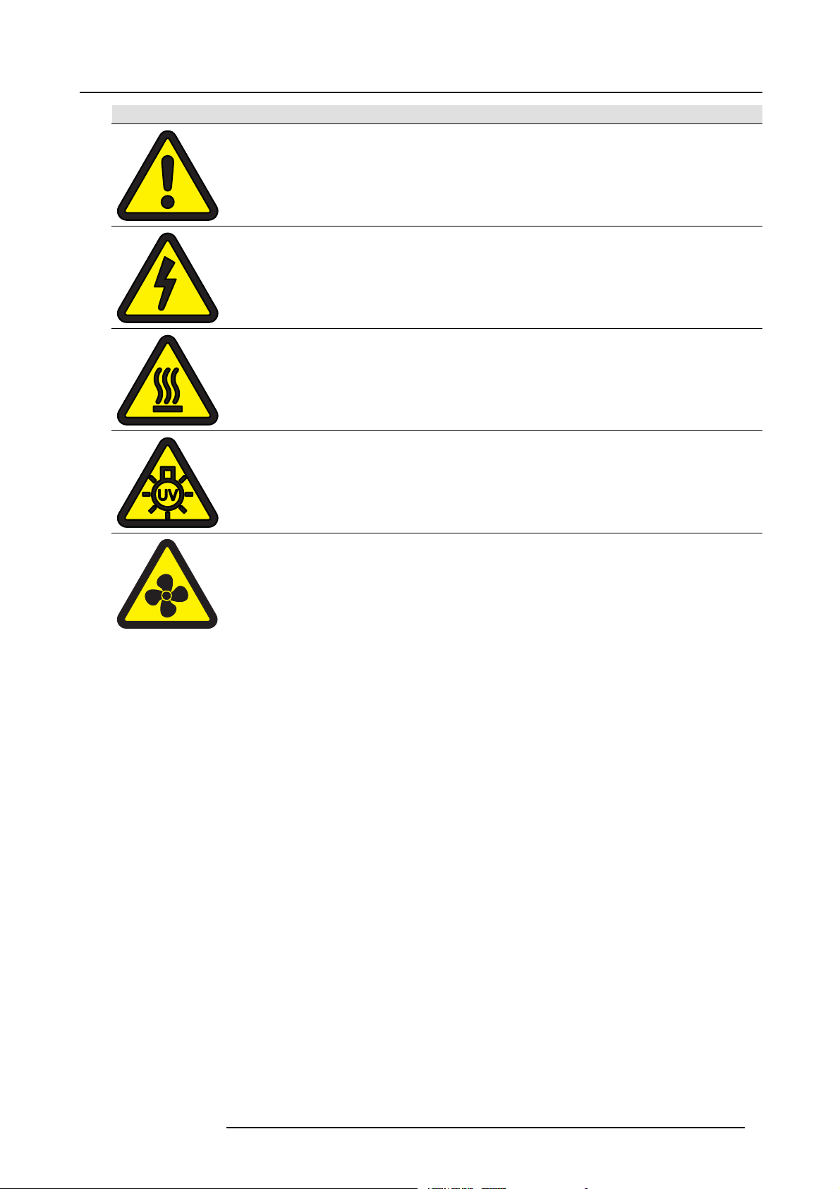
Label image Label description
General Warning Hazard
Electric Voltage Haz ard
Hot Surface Hazard
UV Haza rd
2. Safety
Hazardous moving parts.
Keep away from moving fan blades.
Keep fingers and other body parts away.
601-0311 F35 07/07/2017 9
Page 14

2. Safety
10 601-0311 F35 07/07/2017
Page 15
3. Get to know the projector
3. GET TO KNOW THE PROJECTOR
About
This chapter describes the main features and components of the projector, including available acc essories.
Overview
• Introducing the F35
• Main components
• Accessories and peripherals
3.1 Introducing the F35
Superior performance for professional applications
The F35 is the ideal projector for applications that demand high level performance, reliability and functionality, with standard features
including:
• Fail safe dual UHP-lamp architecture w ith hot–swap capabilities
• Easy monitoring of projector status via LCD status screen, LED s tatus indicator, and LED lamp status indicators
• Built in smear reduction processing (SRP)
• DLP® technology for perfect colors and ultimate reliability
• Motorized lens operation (shift, zoom, focus, iris)
• Dual opto-mechanical iris optimizes brightness and contrast control
• Real time clock (RTC) for programming functions
• BrilliantColor™ technology for better color matching and display
• Compatible with the EN1X and EN4X lens ranges
• Warranted for 24/7 operation
• Minimal maintenance and low total cost of ownership (TCO)
User access levels
The projector’s software platform uses access levels to defi ne what each user can do.
There are three user access leve ls:
User level
Standard Functions that relate to set-up and adjustments for various signal sources suc h as PC’s, video
Power
Service Specialist functions related to tuning, service and repair. Service User code must be input into
Scope
equipment etc. These functions are available directly with the remote control, unless the PIN
(Personal Identity Num ber) code function is activated.
Advanced functions that relate to automation and adaptation of the projector in custom
environments. Power User code must be input into the Service menu to activate additional
functionality.
the Service menu to activate additional functionality.
Projector service (LFM)
The F 35 has no user-serviceable parts. The projector
operating hours (colorwheels) and 16000 hrs (fans). Both of these service tasks mus t only be carried out by the m anufacturer or a
manufacturer-authorized service technician. The On Screen Display (OS D) will generate a Service Reminder when a Low Frequency
Maintenance (LFM) check is required.
fans and color wheels require service or replacem ent, typically after 8000
Projector Consumables
The projector lamps have a normal lifetime of approximately 2000 running hours, though this is dependent on the lamp m ode used.
Experienced users can replace the projector lamp. See "Change the projector lamp", page 77 for details of this procedure.
The projector remote control is powered with two (2) non-rechargeable AA batteries.
CAUTION: Disposal of the projector lamp modules and remote control batteries shall be carried out properly,
and in full accordance with the relevant n ation
al legislation.
601-0311 F35 07/07/2017 11
Page 16
3. Get to know the projector
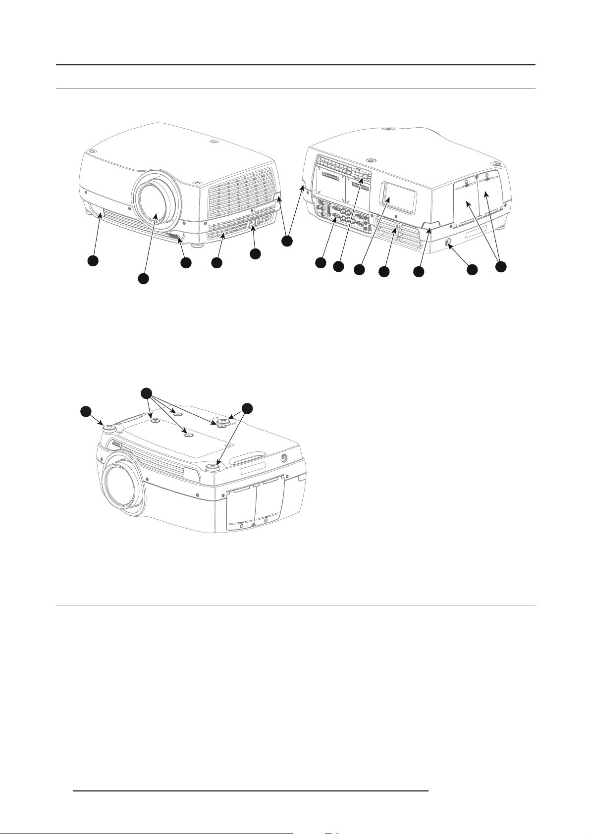
3.2 Main components
Projector components
1
2
2
Image 3-1
1 IR Receivers
2 Lens
3 Lens release button
4 Ventilation
5 Mains power input
6 Connection panel
7 Local keypad
8 LCD status screen
9 Exhaust
10 Kensington™ Lock
11 UHP lamphouse 1,2
1
5
3
4
6
7
8
9
1
10
211
10
11
11
Image 3-2
10 Ceiling mounts (M4)
11 Adjustable feet
11
3.3 Accessories and peripherals
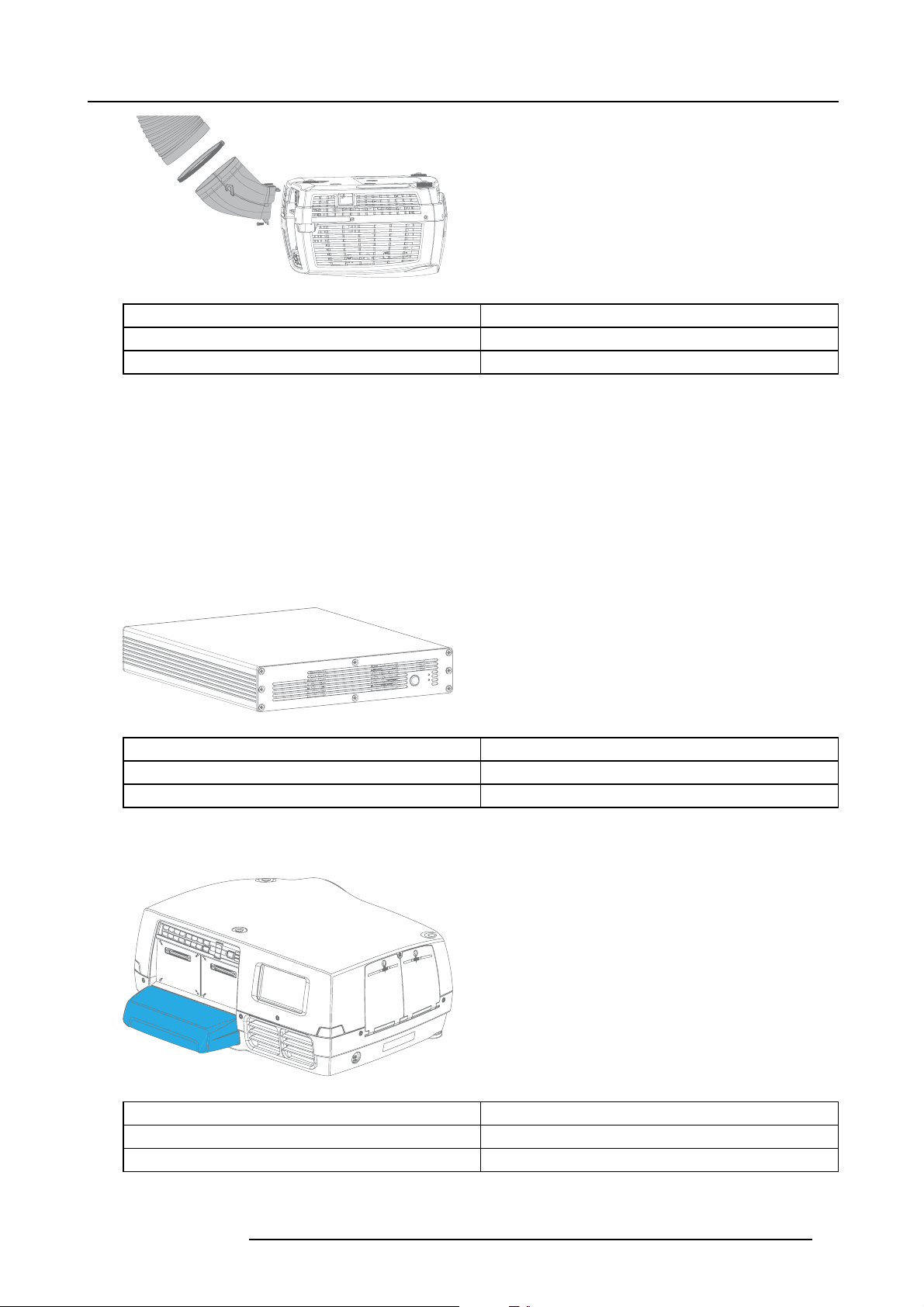
Exhaust air kit
Installing the exhaust air kit is recommended for longer term ceiling-mounted installations. The kit is custom designed for the F35
and works both to dir
Installation and removal of the kit is quick, and requires no specialist tools.
ect the exhaust air from the projector and to reduce the operating noise level.
12
601-0311 F35 07/07/2017
Page 17
3. Get to know the projector
Image 3-3
Item num ber Description
R9801376 Exhaust kit (white)
R9801377 Exhaust kit (black)
External multi-image processor
The Barco image processing engine range offers increased control of warp and blend (W B) operations.
Features of the WB range include:
• Camera-based AutoAlign
• Real time warp
• Support for third party camera based AutoAlign
• Barco’s patented Black Level Matching
• Sub-Pixel Le vel Matching
• User-selectable filtering
• Compatible with all p rojector makes, models and brands
Image 3-4
Item num ber Description
R9801223 WB1920 Image Processor
R9801224 WB2560 Image Processor
Cable cover
The cable cover can b e mounted on the projector to conceal the interface cables and power cord when the unit is ceiling mounted.
Image 3-5
Item num ber Description
R9801283
R9801281
Ceiling cover, pearl white
Ceiling cover, black
601-0311 F35 07/07/2017 13
Page 18
3. Get to know the projector
Projector Toolset
Projector Toolset software is Barco’s proprietary projector management software that allows you to manage your Barco projector
easily and quickly from one central location, via a LAN or RS 232 connection. Comprising various tools for brightness settings,
diagnostics, im age adjustment, picture-in-picture and image control, the Projector Toolset is an indispensable tool for efficient vis u alization management. Projector Toolset is available for Linux, Mac OS X, and Windows.
For more information or to download the Projector Toolset software and user guide, visit the Barco website.
Image 3-6
14 601-0311 F35 07/07/2017
Page 19
4. LENSES
About this chapter
This chapter details the available lenses for the F35, and their technical specifications.
The procedure for replacing a lens, shifting the lens, and adjusting zoom, focus and iris (where applicable) is also described in this
chapter.
The projector lens shift and offset matrix is give n in user manual section, "Lens shift", page 28.
Overview
• Lens range
• Lens monitoring
• Replacing a lens
• Lens shift
• Adjust z oom, fo cus and iris
4.1 Lens range
CAUTION: Alw ays remove the lens from the lens holder before moving or transporting the projector. Failure
to do this may cause damage to the lens holder and prism.
4. Lenses
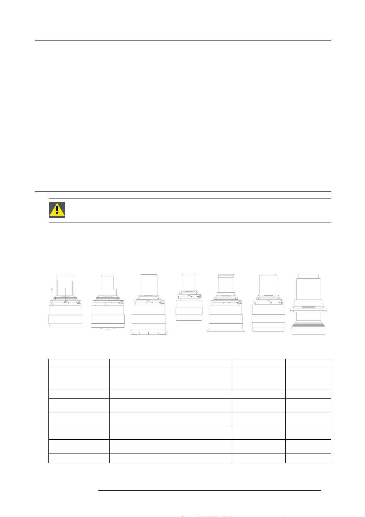
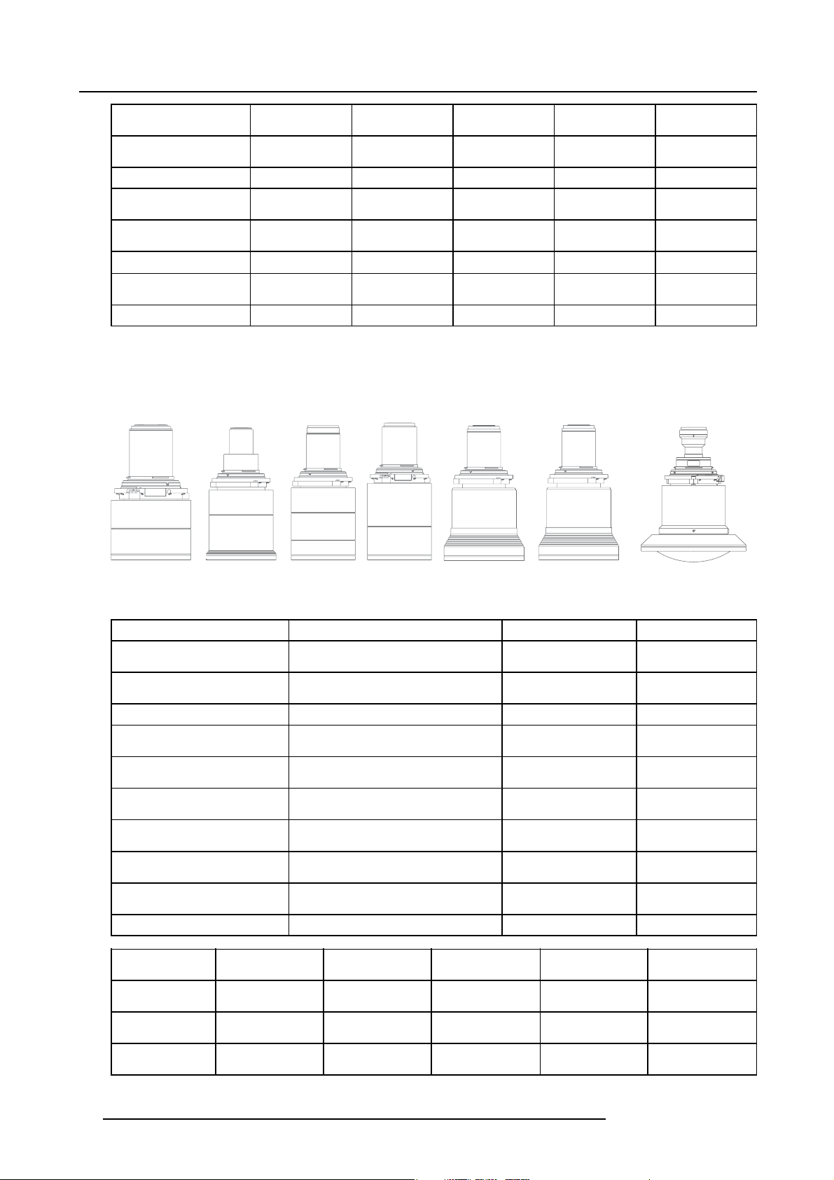
Available lenses — WUXGA
The FLD lens range is custom-engineered for WUXGA and 1080 projectors.
The electrical connection to the lens motors is via a spring probe contact (pogo) pin array on the bayonet mount.
The p rojector will automatically detect and identify the lens when it is installed. Automatic detection is not available for 3rd party
lenses.
EN11 EN12 EN13 EN14 EN15 EN16 EN33
Image 4-1
Name Description Part number Weight
FLD Lens 1.6 - 2.32 : 1
(EN11)
FLD Lens 0.74 : 1 (EN12) 0.74:1 (WUXGA)
FLD Lens 1.24 - 1.6 : 1
(EN13)
FLD Lens 2.37 - 3.79 : 1
(EN14)
FLD Lens 1.16:1 (EN15) 1.16 : 1 (W UXG A) R9801225 2.4 kg
1.6-2.32 : 1 (WUXGA)
1.24 - 1.6 : 1 (WUXGA)
2.37 - 3.79 : 1 (WUXGA)
R9801214 2.2 kg
R9801218 1.9 kg
R9801228 2.6 kg
R9801209 2.5 kg
FLD Lens 3.80 - 6.50 : 1
(EN16)
FLD Lens 0.92: 1 (EN33 0.92 : 1 (W UXG A)
601-0311 F35 07/07/2017 15
3.8 - 6.5 : 1 (W UX GA) R9801249 2.5 kg
R9801227 0.9 kg
Page 20
4. Lenses
Name
FLD Lens 1.6 - 2.32 : 1
(EN11)
FLD Lens 0.74 : 1 (EN12) 2.1 Yes 2.1-6.5
FLD Lens 1.24 - 1.6 : 1
(EN13)
FLD Lens 2.37 - 3.79 : 1
(EN14)
FLD Lens 1.16:1 (EN15)
FLD Lens 3.80 - 6.50 : 1
(EN16)
FLD Lens 0.92: 1 (EN33
Working F# Iris / Iris F#
2.1-2.52 Yes 2.1-6.5 1.45 33.2-48.1 2.0-15
2.1-2.22 Yes 2.1-6.5 1.3 25.59-33.24 1.0-15
2.1-2.72 Yes 2.1-6.5 1.6 49.1-78.6 3.0-30
2.1 Yes 2.1-6.5
2.1-2.66 Yes 2.1-6.5 1.74 78.3-136.2 4.0-40
2.6 No
Zoom Ratio Focal Length
-
-
-
(mm)
16.35 0.5-5
23.98 1.5-15
19.7 1.0 — 10
Focus Range (m)
Available lenses — 4K, WUXGA, WQXGA
The FLD+ (EN4X) lens range is custom-engineered for WQXGA projectors.
The electrical connection to the lens motors is via a spring probe contact (pogo) pin array on the bayonet mount. The projector will
automatically detect and identify the lens when it is installed. Auto matic detection is not available for 3rd party lenses.
EN41
Image 4-2
Name Description Part number Weight
FLD+ Lens 1.7 - 2.5 : 1 (EN41) 1.58 - 2.33 : 1 (WUXGA) / 1.7 - 2.5 : 1
FLD+ NV Lens 1.7 - 2.5 : 1
(NV41)
FLD+ Lens 0.8 : 1 (EN42) 0.75 : 1 (WUXGA) / 0.8 : 1 (WQXGA) R9801226 2.7 kg
FLD+ Lens 1.2 - 1.7 : 1 (EN43) 1.12 - 1.58 : 1 (WUXGA) / 1.2 - 1.7 : 1
FLD+ NV Lens 1.2 - 1.7 : 1
(NV43)
FLD+ Lens 2.5 - 4.6 : 1 (EN44) 2.33 - 4.3 : 1 (WUXG A) / 2.5 - 4.6 : 1
FLD+ Lens 0.75 - 1 .13 : 1 (EN45) 0.75 - 1.13 : 1 (WUXGA) / 0.8 - 1.21 :
FLD+ Lens 0.75 - 1 .13 : 1 (EN46) 0.75 - 1.13 : 1 (WUXGA) / 0.8 - 1.21 :
FLD+ NV Lens 0.8 - 1.21 : 1
(NV46)
FLD+ Lens 0.65 : 1 (EN47) 0.61 : 1 (WUXGA) / 0.65 : 1 ( W QXG A)
Name
FLD+ Lens 1.7 -
2.5 : 1 (EN41)
FLD+ NV Lens 1.7
- 2.5 : 1 (NV41)
FLD+ Lens 0.8 : 1
(EN42)
EN42 EN43 EN44 EN45 EN46
(WQXGA)
IR Optimized, 1.58 - 2.33 : 1 (WUXGA) /
1.7-2.5: 1(WQXGA)
(WQXGA)
IR Optimized, 1.12 - 1.58 : 1 (WUXGA) /
1.2-1.7: 1(WQXGA)
(WQXGA)
1(WQXGA)
1(WQXGA)
IR Optimized, 0.75 - 1.13 : 1 (WUXGA)
/ 0.8 - 1.21 : 1 (WQXGA)
Working F# Iris / Iris F#
2.1-2.5 Yes 2.1-6.5 1.47 33.70-49.54 1.5 - 15
2.1-2.5 Yes 2.1-6.5 1.47 33.70-49.54 1.5 - 15
2.1 Yes 2.1-6.5
Zoom Ratio Focal Length
-
R9801216 2.54 kg
R9801216 2.54 kg
R9801230 2.84 kg
R9801286 2.84 kg
R9801211 3.08 kg
R9801220 3.04 kg
R9801221 3.14 kg
R9801287 3.14 kg
R9801295 5.4 kg
Focus Range (m)
(mm)
16.12 0.7 - 7
EN 47
16 601-0311 F35 07/07/2017
Page 21
4. Lenses
Name
FLD+ Lens 1.2 -
1.7 : 1 (EN43)
FLD+ NV Lens 1.2
- 1.7 : 1 (NV43)
FLD+ Lens 2.5 -
4.6 : 1 (EN44)
FLD+ Lens 0.75 -
1.13 : 1 (EN45)
FLD+ Lens 0.75 -
1.13 : 1 (EN46)
FLD+ NV Lens 0.8
-1.21: 1(NV46)
FLD+ Lens 0.65 :
1 (EN47)
Working F# Iris / Iris F#
2.4-2.7 Yes 2.4-6.5 1.42 23.95-34.02 1.5 - 15
2.4-2.7 Yes 2.4-6.5 1.42 23.95-34.02 1.5 - 15
2.1-2.93 Yes 2.1-6.5 1.85 49.52-91.60 2.5-25
2.4-3.29 Yes 2.4-6.5 1.51 15.85-23.93 5.0 - 30
2.4-3.29 Yes 2.4-6.5 1.51 15.98-23.99 0.7 - 7
2.4-3.29 Yes 2.4-6.5 1.51 15.98-23.99 0.7 - 7
2.1 Yes 2.1-6.0
Zoom Ratio Focal Length
-
(mm)
12.6 0.5 - 4.0
Focus Range (m)
4.2 Lens monitoring
Using 3rd party lenses with the F35
The F35 features an automatic lens monitoring functionality that identifies when a lens is installed or removed and automatically
opens the lens shutter and realigns the DMD.
The bayonet mount is fitted with a spring probe contact (pogo) pin array that detects standard Barco FLD/FLD+ lenses. When an
FLD/FLD+ lens is installed, the projector detects this and o pens the mechanical lens shutter and moves the DMD to the ’On’ position.
The reverse happens when a lens is removed.
Non standard or passive lenses, such as the EN33, the HR95 and 3rd party lenses, do not facilitate automatic lens monitoring. In
these instances, Lens Monitoring must be disabled and the lens s hutter manually opened and closed.
Disabling the Lens Monitor function can be done:
•ViatheOSD,Main menu — Settings — Service — Lens Monitor
• Via the RS-232 control interface
• Via the Barco GP3 Lens Monitoring app, available for download from the product w ebsite
You must have Power or Service User rights to enable or disable lens monitoring.
Once Lens Monitoring is disabled, use the SHUTTER function on the wireless remote control, local key pad or via your RS-232
control interface to manually open and close the lens shutter.
4.3 Replacing a lens
CAUTION: When changing p rojection lens, exercise great care wh en inserting or extracting the lens to pre-
vent damage to the ‘pogo’ pins in the bayonet mount.
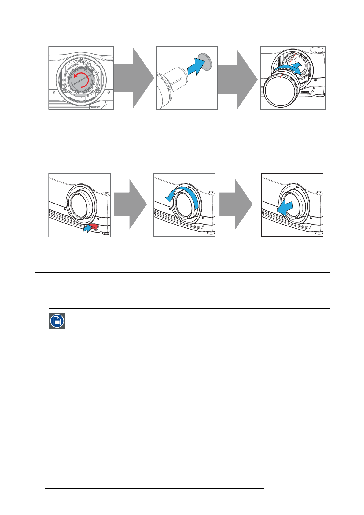
Install a lens
1. R emov e the lens m ount protection c ap on the projector.
2. Remove the lens cap at the bayonet
3. A lign the lens so that the red line on the lens bayonet is pointing towards the top of the projector cabinet.
4. Insert the lens bayonet into the lens mount and turn clockwise until the pogo pins engage and the lens clicks into position.
Caution: The lens is fragile. Do not try to force the lens into position. If there is any resistance, remove the lens from the
projector and then try again.
end of the lens.
601-0311 F35 07/07/2017
17
Page 22
4. Lenses
Image 4-3
Removealens
1. Depress and hold the lens release button.
2. Turn the lens anticlockwise until the bayonet is free of the lens mount.
3. P ull the lens straight out of the lens mount.
Note: To prevent damage to the lens or dust contamination in the projector light processor, always replace the lens bayonet
cap, lens cap and projector lens cap (if applicable) immediately after removing the lens.
Image 4-4
4.4 Lens shift
General
This section describes how to shift the lens using the projector keypad and the r emote control.
For information on the available sh ift and offset values for each lens, see "Lens shift", page 28.
All F35 lenses have limited downwards shift.
Lens shift can also be carried out via the R S232 communication interface. See the ASCII Commands Protocol for more details.
Shift the lens using the keypad
1. P ress SHIFT to activate lens shift
2. U se the arrow keys to m ove the lens up, down, left, and right.
Shift the lens using the remote control
1. P ress the SHIFT button to activate lens shift.
2. U se the navigation arrows to move the lens up, down, left and right.
4.5 Adjust zoom, focus and iris
General
Zoom controls the size of the projected image.
Focus controls the sharpness of the projected image.
18
601-0311 F35 07/07/2017
Page 23

4. Lenses
Iris controls the contrast and focus depth of the image. Dec reasing the iris stop will increase contrast and image depth, at the same
time as it decreases brightness.
Lens zoom, focus and iris adjustments are motorized. You can use the remote control, local keypad, OSD and/or RS -232 commands
to adjust the lens zoom , focus and iris positions.
Not all lenses have zoom or iris control. The matrix b elow shows what controls are available per lens.
EN11 EN12 EN13 EN14 EN15 EN16 EN33 EN41 EN42 EN43 EN44 EN45 EN46 EN47
Iris
Zoom
Focus
For best results, lens adjustments should be done in the following order: zoom, focus and then iris (w here applicable).
✔✔✔✔✔✔
✔
✔✔✔✔✔✔✔✔✔✔✔✔✔✔
✖
✔✔
✖
✔
✖
✔✔✔✔✔✔✔
✖
✔
✖
✔✔✔✔
✖
601-0311 F35 07/07/2017
19
Page 24

4. Lenses
20 601-0311 F35 07/07/2017
Page 25

5. Installation
5. INSTALLATION
General
This chapter explains how to physically install the projector, and what considerations you should take whe n designing and s etting
up the projection installation. E ach projector installation is unique, and as such the information in this chapter is only provided as a
guideline. Likewise, any images or graphical representations show n here are for illustrative purposes only.
If you require further information and assistance during the installation process, contact a qualified projection technician or your local
support office for advice.
For information on setting up multi-channel installations, see user manual chapter "Setup a multichannel installation", page 63.
Overview
• Installing the projector
• Installation conditions
• Initial inspection
• Positioning the projector
• Mount the projector on a fl at surface
• Mount the projector on the ceiling
• Throw distance
• Lens shift
•OffsetMatrix
• Scheimpflug (Boresight) adjustment
• Scheimpflug adjustment procedure
5.1 Installing the projector
Installation sequence
1. Verify the installation area meets the physical and environmental requirements of the projector as outlined in "Installation condi-
tions", page 21.
2. Decide where the projector w ill be mounted. See "Positioning the projector", p age
the be st physical location.
3. Unpack the projector, and check that all equipment is present and in good working order. See "Initial inspection", page 23.
4. M ount the projector. The projector can be mounted on a flat surface, see "Mount the projector on a flat surface", page 24 or using
a ceiling-mount, see "Mount the projector on the ce iling", page 25.
5. C onnect the video and/or data sources. See "Connector Panel", page 38 for more information and specification s.
6. Install the projector lens. See "Replacing a lens", page 17.
7. Connect the projector to the mains powe r net. The projector will go through the initialization proc ess. Progress will be displayed
on the LCD screen.
8. O nc e the initialization progress is complete , the projector status indicator will turn to steady orange. See section "Projec tor status
indicator", page 34 for more information on the projector status indicator.
9. P ress the power button on the k eypad or remote control to start the warm up proce ss. The status indicator will turn to steady
green when the projector is warmed up and ready for use.
10.Select the display s ource. Read more about sources, in
Communication", page 33.
11.Adjust the projected image on the screen. Read chapter "Set up the pic ture", page 49 for more information.
cluding technical specifications, in the User Manual chapter "Input and
23 for guidelines and advice on determining
5.2 Installation conditions
General
This section contains important physical and env ironmental information that will help you determine the optimal installation pos ition
and conditions for your projector.
601-0311 F35 07/07/2017
21
Page 26
5. Installation
Barco projectors are manufactured according to specifi c design standards, which also include environmental
conditions. Failing to follow the terms and conditions outlined in this chapter can result in loss of product
warranty.
Environmental conditions
The table below summarizes the physical environment in which the projector may be safely operated or stored.
Environment Operating Non-Operating
Ambient Temperature @
1500 m
Ambient Temperature @
3000 m
Air cleanliness
Relative Humidity (RH) 20% to 80% RH Non-condensed 10% to 90% RH Non-Condensed
10 °C (50 °F) to 40 °C (104 °F) -20 °C (-4 °F) to 60 °C (140 °F)
10 °C (50 °F) to 35 °C (95 °F) -20 °C (-4 °F) to 60 °C (140 °F)
Clean office environment
n.a.
Mains power requirements
Projector Power requirements
F35
To protect operating personne l, the National Electrical Manufacturers Association (NEM A) recommends that the instrument panel
and cabinet be grounded. In no event shall this p rojector be operated without an adequate cabinet ground connection.
The AC supply must be installed by a qualified electrician in conformance to local codes. Hardware, wire sizes and conduit types
must comply with local codes.
100 — 240 V, 50 — 60 Hz, 16 A @ 240 V
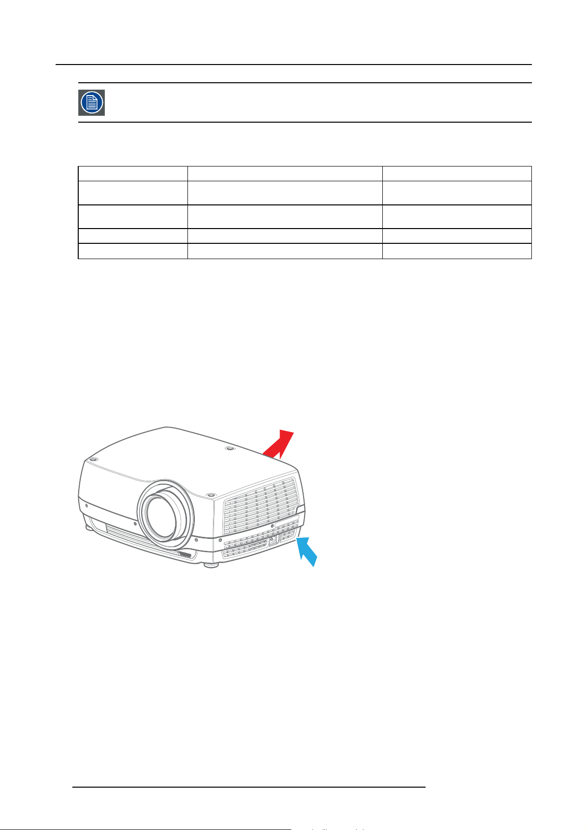
Ventilation
The projector is fan cooled and must be installed with sufficient space around the projector to ensure sufficient air flow.
Ventilation inlets are loc ated on the left side of the projector. Hot air is exhausted from the rear vent, see image 5-1.
Min. 50 cm
to nearest object
Min. 20 cm
Image 5-1
to nearest object
Projector weight and footprint
Weight: 13 kg (exclusive o f lens)
22
601-0311 F35 07/07/2017
Page 27
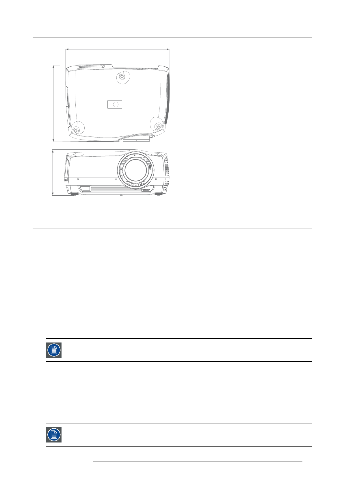
376 mm
223.4 mm
Image 5-2
5. Installation
510 mm
5.3 Initial inspection
General
Each projector is inspected and rigorously tested at our production facility to ensure that it is free from any mechan ical or electrical
defects.
Upon receipt of the projector, we recom mend that customers inspect the projector for any signs of damage that may have occurred
in transit. If damage is found, file a claim with the shipping carrier im mediately. Notify the Barco Sales and Se rvice office, or your
preferred Barco agent, of the damage as soon as possible.
Box Contents
Your projector box should contain the following:
• Projector unit
• Power cord (suitable for region)
• Quick start guide
• Safety manual
• Remote Control
The projector lens is delivered in a separate box.
5.4 P ositioning the projector
General guidelines
Proper positioning of the projector will ensure a better image on screen and may lessen the time needed to adjust and align the
image on screen.
Focus and sharpness of the image c
projection surface.
601-0311 F35 07/07/2017 23
an be adversely affected if the lens axis is not fully perpendicular to the
Page 28

5. Installation
The following guidelines can help you determine the best physical location for the projector.
• The ambient air temper ature of the room or enclosure should not be greater than 40 °C (at 1500 m altitude), and there must be
sufficient ventilation area around the projector. See section "Installation c onditions", page 21 for more detailed information.
• Use the throw r atio of the installed lens as a guideline for determ ining the projector’s physical distance from the s creen. See
"Throw distance", page 25 for more information.
• Ensure that the source signal interface and cable lengths are matched to the installation. In general:
- 3G-SDI a re long-haul interfaces and suitable for bespok e installations using relatively long cables
- DP, HDMI, DVI and VG A are short-haul interfaces using pre-assem bled cables with limited cable lengths. Using extended
cable lengths may result in reduced image quality as well as loss of control information such as EDID (Extended Display
Information Data).
• Wherever possible, the projector lens surface sh ould be positioned so that it is perfectly perpendicular to
screen. Offset (lens shift), rather than physical angling, should be used primarily to c orrect any off-center positioning.
• Installing the projector on a tilt is not recommended as it may impact negatively on lamp and image performance. If it is absolutely necessary to install the projector on an angle, ensure that it is w ithin the guidelines illustrated in image 5-3
the center of the
+ 20˚
360˚
- 20˚
Image 5-3
5.5 Mount the projector on a flat surface
Suggested procedure
1. P lace the projector on a pedestal or similar, sturdy object. Make sure that all three projector feet are in contact with the surface
of the installation area.
2. A djust the projector legs so that so that the projector is completely level. To do this, turn the collar on each foot clockwise or
anti-clockwise until the c orrect level is achieved.
Lower
Image 5-4
3. In an ideal installation, the projector lens surface is centered with and parallel to the screen. This orientation helps to ensure
optimized lens performance with minimal offset. If this position is not poss ible (such as when the projector is significantly higher
than the center of the screen), it is better to rely on offset (lens shift) rather than extra tilt. If tilt is required, mak e sure that it does
not exceed 20 degrees on the s ide-to-side axis, as illustrated in image 5-3.
Raise
24
601-0311 F35 07/07/2017
Page 29

5. Installation
5.6 Mount the projector on the ceiling
Necessary tools
Screwdriver, type dependent on screws used.
Necessary parts
• Ceiling mount or rig frame
• 4x M4 screws, us er supplied. See procedure be low for information on sizing.
Suggested procedure
1. C onfi rm that the physical c onditions of the proposed installation area c omplies with the projector installation requirements.
2. In an ideal installation, the projector lens surface is centered with and parallel to the screen. This orientation helps to ensure
optimized lens performance with minimal offset. If this position is not poss ible (such as when the projector is significantly higher
than the center of the screen), it is better to rely on offset (lens shift) rather than extra tilt. If tilt is required, mak e sure that it does
not exceed 20 degrees on the s ide-to-side axis, see "Positioning the projector", page 23.
3. T here are four (4) mount holes that are used to install the projector onto a ceiling mount or rig frame. See image 5-5.
1
Image 5-5
4. Installation screws are not supplied by the manufacturer. The length of the screw is dependent on the dimensions o f the ceiling
mount or frame you are using. The screw should not protrude more tha
Caution: Correct screw length is extremely important. Failing to observe these limitations may c ause damage to your projector.
5. Install the projector to the ceiling mount or rig frame using the four screws. Do not ov ertighten!
n 15 mm into the projector chassis.
5.7 Throw distance
Calculate the installation throw distance
Throw is the distance (D) measured from your projector lens to the screen. To calculate the throw distance for an installation, you
will need two pieces of data: the selected lens throw ratio (L) and the horizontal width (W) of the screen. For example, if the screen
width (W) is 2.4 m eters and the projector lens has a
Calculation: 2.4 x 0.99 = 2.38
The following graphs illustrate the image size (W) and projection distance (D) for each of the projector lenses.
Tolerances are typically +/- 5% due to optical (lens) variation.
throw ratio (L) of 0.99:1, then the throw distance (D) will be 2.38 meters.
601-0311 F35 07/07/2017 25
Page 30

5. Installation
Throw distance, FLD WUXGA
7.50
Image width
m
12.00
Screen diagonal
14.00
7.00
6.50
6.00
5.50
5.00
4.50
4.00
3.50
3.00
2.50
2.00
1.50
1.00
0.50
0.00
FLD Lens 0.74:1 (EN12) (0.5 - 5m)
FLD Lens 1.16:1 (EN15) (1.5 - 15m)
FLD Lens 1.24 - 1.6 : 1 (EN13) (1.0 - 15m)
FLD Lens 1.6 - 2.32 : 1 (EN11) (2.0 - 15m)
FLD Lens 2.37 - 3.79 : 1 (EN14) (3.0 - 30m)
FLD Lens 3.80 - 6.50 : 1 (EN16) (4.0 - 40 m)
11.00
10.00
9.00
8.00
7.00
6.00
5.00
4.00
3.00
2.00
1.00
0.00
13.00
12.00
11.00
10.00
9.00
8.00
6.00
5.00
4.00
3.00
2.00
1.00
0.00
Image 5-6
Projection distance
26 601-0311 F35 07/07/2017
Page 31

Throw distance, FLD+ WQXGA
Image height
7.50
5. Installation
Image width
m
12.00
Screen diagonal
14.00
7.00
6.50
6.00
5.50
5.00
4.50
4.00
3.50
3.00
2.50
2.00
FLD+ Lens 0.65 : 1 (EN47) (0.5 - 4m)
1.50
1.00
0.50
0.00
FLD+ Lens 0.8 : 1 (EN42) (0.7 - 7m)
FLD+ Lens 0.8 - 1.21 : 1 (EN46) (0.7 - 7m)
FLD+ Lens 0.8 - 1.21 : 1 (EN45) (5 - 30m)
FLD+ Lens 1.2 - 1.7 : 1 (EN43) (1.5 - 15m)
FLD+ Lens 1.7 - 2.5 : 1 (EN41) (1.5 - 15m)
FLD+ Lens 2.5 - 4.6 : 1 (EN44) (2.5 - 25 m)
11.00
10.00
9.00
8.00
7.00
6.00
5.00
4.00
3.00
2.00
1.00
0.00
13.00
12.00
11.00
10.00
9.00
8.00
6.00
5.00
4.00
3.00
2.00
1.00
0.00
Image 5-7
Projection distance
601-0311 F35 07/07/2017 27
Page 32

5. Installation
Throw distance, FLD+ WUXGA
7.50
Image width
m
12.00
Screen diagonal
14.00
7.00
6.50
6.00
5.50
5.00
4.50
4.00
3.50
3.00
2.50
2.00
1.50
1.00
0.50
0.00
FLD+ Lens 0.65 : 1 (WUXGA) (EN47) (0.5 - 4m)
FLD+ Lens 0.75 - 1.13 : 1 (WUXGA) (EN46) (0.7 - 7m)
FLD+ Lens 0.75 : 1 (WUXGA) (EN42) (0.7 - 7m)
FLD+ Lens 0.75 - 1.13 : 1 (WUXGA) (EN45) (5 - 30m)
FLD+ Lens 1.12 - 1.58 : 1 (WUXGA) (EN43) (1.5 - 15m)
FLD+ Lens 1.58 - 2.33 : 1 (WUXGA) (EN41) (1.5 - 15m)
FLD+ Lens 2.33 - 4.3 : 1 (WUXGA) (EN44) (2.5 - 25 m)
11.00
10.00
9.00
8.00
7.00
6.00
5.00
4.00
3.00
2.00
1.00
0.00
13.00
12.00
11.00
10.00
9.00
8.00
6.00
5.00
4.00
3.00
2.00
1.00
0.00
Image 5-8
Projection distance
5.8 Lens shift
Adjusting the horizontal and vertical position of the i mage
Ideally in any ins tallation the projector is po sitioned totally perpendicular to the screen to ensure a wholly rectangular image. However, physical limitations mean th
One way to correct this is by adjusting, or shifting, the vertical or horizontal position of the image.
The amount of available vertical or horizontal offset is dependent on what type of lens is installed in the projector and the projector
resolution, see image 5-9 which illustrates the vertical offset values of an image. The same theory applies to horizontal shift. The
middle of the image is the optical a xis (0%), i.e. no shift. 100% shift equals half of t he image height.
at this is not always possible to do and the result is a trapezoidal effect upon the displayed image.
W
-100%
H
Image 5-9
On axis (0% shift)
0%
+100%
Front elevation Side elevation
On axis (0% shift)
0% Lens Shift e quals on axis (i.e. no shift). 100% Lens Shift equa l s half of image height / width.
28 601-0311 F35 07/07/2017
Page 33

5. Installation
Vertical lens shift formula
Vertical shift = Screen Height x (Max. Lens S hift Vertical (%) ÷ 2) ÷ 100
If the screen is 1.2 m eters high and the vertical lens offset value is +120% to +150% (min/max), then the v ertical lens shift will be
75% (0.9 meters). T his means that the (centre of the) image can be shifted up or down a maximum of 90 centimeters.
Calculation: 1.2 * (150 ÷ 2 = 75) 75 ÷ 100 = 0.9
Horizontal lens shift formula
Horizontal shift = Screen Width x (Max Lens Offset Horizontal (%) ÷ 2) ÷ 100
If the screen is 4.2 meters wide and the horizontal lens m axim um offset value is +42% , then the horizontal lens shift will be 21%
(0.89 meters). This m eans that the (centre of the) image can be shifted left or right by a maximum of 89
Calculation: 4.2 * (42 ÷ 2 = 21) 21 ÷ 100 = .882
1
centimeters.
Motorized lens shift
The F35 lens shift function is fully motorized and can be controlled via the projector keypad, wireless remote c ontrol, or wired control
interface e.g. RS-232.
To activate lens shift, press the SHIF T button on the keypad or remote control. Use the corresponding arrows to m ove the lens up,
down, right and left.
For information on using the RS-232 or LA N control interfaces, please refer to the relevant ASCII Commands Protocol available for
download at www.barco.com.
5.9 Offset Matrix
F35 offset matrix
EN11 EN12 EN13 EN14 EN15 EN16 EN33
+/- (%) +/- (%) +/- (%) +/- (%) +/- (%) +/- (%) +/- (%)
1080
Vertical 150 20 150 150 150 150 84
Horizontal 68 6 68 68 68 68 32
SXGA+
Vertical 120 10 120 120 120 120 60
Horizontal 80 6 80 80 80 80 38
WUXGA
Vertical 134 8 134 134 134 134 66
Horizontal 68 4 68 68 68 68 30
EN41 EN42 EN43 EN44 EN45 E N46 EN47
+/- (%) +/- (%) +/- (%) +/- (%) +/- (%) +/- (%) +/- (%)
1080
Vertical 146 0 114 146 50 50 72
Horizontal 60 0 48 60 18 18 28
SXGA+
Vertical 106 0 84 106 30 30 50
Horizontal 70 0 52 70 20 20 30
WUXGA
Vertical 120 0 100 120 34 34 60
Horizontal 60 0 44 60 14 14 26
Panorama
Vertical 212 52 21 212 130 130 164
1. rounded up to two decimal points
601-0311 F35 07/07/2017 29
Page 34

5. Installation
EN41 EN42 EN43 EN44 EN45 E N46 EN47
+/- (%) +/- (%) +/- (%) +/- (%) +/- (%) +/- (%) +/- (%)
Horizontal 78 10 78 78 32 32 42
WQXGA
Vertical 146 0 116 144 50 50 80
Horizontal 70 0 56 70 24 24 36
5.10 Scheimpflug (Boresight) adjustment
What is Scheimpflug?
The lens holder has to be adjusted s o that the “sharp focus plane” of the projected image falls toge
(Fp1→Fp2). This is achieved by changing the distance between the DMD plane and the lens plane (Lp1→Lp2). The closer the lens
plane comes to the DMD plane the further the sharp focus plane will be. It can occur that you won’t be able to get a complete focused
image on the screen due to a t ilt (or swing) of the lens plane with respect to the DMD plane. Th
law. To solve this the lens plane must be placed parallel with the DMD plane. This can be achieved by turning the lens holder to
remove the tilt (or swing) between lens plane and DMD plane (Lp3→Lp4).
ther with the plane of the screen
is is also known as Scheimpflug’s
Lp1
Lp2
DMD
Image 5-10
Scheimpflug principle
Scheimpflug principle
The "plane of sharp focus" can be changed so that any plane can be brought into sharp focus. W hen the DMD plane
and lens plane are parallel, the plane of sharp focus will also be parallel to these two planes. If, however, the lens
plane is tilted with r espect to the DMD plane, the plane of sharp focus will also be tilted according to geometrical and
optical properties. The DMD plane, the principal lens plane and the sharp focus plane will intersect in a line be low the
projector for downward lens tilt.
SCREEN
Fp1
Fp2
DMD
Lp3
Lp4
(Scheimpflug)
Fp4
Fp3
SCREEN
Scheimpflug adjustment points
Scheimpflug adjustment points are located on the lens mount. The F35 has three (3) set screws and three (3) adjustment screws.
When to apply Scheimpflug?
Scheimpflug correction procedures may only be carried out by suitably trained and experienced tech nicians.
A Scheimpflug correction should only be applied w h en the overall focus of the projected image is not equally sharp (for example, if the
projector is NOT in parallel with the screen or as a result of a previously misaligned Scheimpfl ug). Be aware that the consequence of
applying Scheim pflug correction upon a screen not in parallel with the projector is that the projected image differs from the rectangle
shaped image. In other words “distortion” of the projected image occurs. Masking will be required to solve the distortion.
The disadvantage of Masking
projection screen and use the SHIFT functionality of the Lens Holder to match the projected image with the projection screen. If the
SHIFT range is not sufficient then the projector can be tilted and Scheimpflug can be applied.
30
is loss of content. Therefore it is strongly recommended to place the projector in parallel with the
601-0311 F35 07/07/2017
Page 35

5. Installation
5.11 Scheimpflug adjustment procedure
Necessary tools
• Scheimpflug tool, size 4 hex
• Projector screen
• Focus plane / Scheimpflug test pattern
Preparation
1. P repare the test area. Barco recommends a projector-screen distance of 2 m etres be used for all Sc heimpfl ug adjustments; this
ensures continuity. Verify that the throw ratio of the installed lens matches the requirements of the installation area (projection
distance and screen size).
2. Check that the lens is correctly installed, and lens shift is in centre position.
3. P roject the chosen test image on the screen.
4. Z oom the lens to its widest opening (maximum image size on the screen).
Apply a Scheimpflug adjustment
1. L oosen the three set screws (reference 1, 2, 3).
1
A
B
2
Image 5-11
2. A djust the top inner Scheimpflug adjustment screw (reference A) until the test image at the lower center of the screen is in focus.
Note: This process may ca use the other areas of the image to slide out of focus . This is totally normal.
C
3
A
F
Image 5-12
3. A djust the bottom left side Scheimpflug adjustment screw ( reference B) until the test image in the top right side of the screen is
in focus.
Note: This process may ca use the other areas of the image to slide out of focus . This is totally normal.
601-0311 F35 07/07/2017 31
Page 36

5. Installation
B
Image 5-13
4. A djust the bottom right side Scheimpflug adjustment screw (reference C) until the test image in the top left s ide of the screen is
in focus.
Note: This process may ca use the other areas of the image to slide out of focus . This is totally normal.
F
C
Image 5-14
F
5. Continue fine-tuning of the ad justment screws (a, b , c) one at a time until the test image is uniformly sharp across all areas of
the display.
6. Test the focus by zooming out (minimum image size on screen) and then zooming in again. Verify the image is sharp for all zoom
positions. If there are any dev iations to sharpness in one or more areas, repeat steps 2 to 6 until the im age is uniformly sharp.
7. Tighten the three set screws in the following order: 1, 2, 3.
Regarding Scheimpflug adjustment in comb ination with the lenses E N 12, 13, 15, 42, 43 and 45.
There is a sm all po ssibility that these lenses can interfere with the shutter function. This can occur when
the adjustment screws for the scheimpflug are adjusted to the end positions. Therefore, a fter scheimpflug
adjustment, always verify normal shutter operation.
If normal operation is not obtained, readjust the scheimpflug, and avoid adjusting to the end position of the
adjustment screws.
32 601-0311 F35 07/07/2017
Page 37

6. Input and Communication
6. INPUT AND COMMUNICATION
About this chapter
This chapter describes the functionality of the projector keypad, status indicators, LC D panel, wireless remote control and connector
panel, as well as details the technical specifications of the input source connections.
Source/input compatibility is dependant on projector configuration.
For information about RS-232 communications, download the Communication Protocol guide f rom the
Overview
• Local key pad
• Projector status indicator
• Lamp status indicators
• LCD Panel
• Turn the LCD screen and LED indicators ON or OFF
• Wireless remote c ontrol
• Connector Pa nel
• Connect to a source
•LAN
•3DSYNC
• RS-232
•SyncIn/Out
• Dual link DVI
•VGA
•YPbPr
• HDMI
•WiredIR
• Triggers
•USBA
•USBB
product website.
6.1 Local keypad
About
The projector keypad is located at the back of the projector, directly above the connector panel. The keypad can be u sed to:
• navigate the menu system
• scroll the information in the LCD panel
• directly select input sources
• enter pin code (when enabled)
• power on/down the projector
• adjust basic lens s ettings including shift, zoom, iris and focus
Keypad backlight
The keypad is illuminated for operation in dark environments. Available functions are illuminated in yellow. Active (selected) functions are illuminated in gre en. Functions that are not available are not illuminated.
The keypad backlight will automatically extinguish after a set period of inactivity (default: 30 seconds). Pressing any button will
re-illuminate the backlight.
Users can set the time-out period from t he OSD M ain Menu — Settings — Backlight timeout.
601-0311 F35 07/07/2017
33
Page 38

6. Input and Communication
The backlight time-out settings include Always O n and Always Off.
Connector panel light
The light key (reference 1) on the local keypad will turn the connector panel side light ON a nd OFF.
1
Image 6-1
Keypad functions
2 3
Image 6-2
Item No. Description
2
3
4
5
6
Direct source selection. Numeric input (1,6) for PIN entry.
Lens functions. Numeric input (2,3,4,7,8,9) for PIN entry.
Show or hide OSD menu. Numeric input (5) for PIN entry.
Navigation keys: can be used for navigation of Lens Shift, LCD display, and OSD.
Reacquire the current source; auto-correct source phase and frequency. Numeric input (0) for PIN e ntry.
6.2 Projector status indicator
About
The projector status indicator (reference 9) is located on the projector keypad.
4
6
5
9
Image 6-3
The indicator shows the current status of the projector and can be used to troubleshoot operating issues.
Indicator Description Action required
Green (steady)
Yellow (steady) Standby (off) Press the power button to bring the p rojector out of standby or
34 601-0311 F35 07/07/2017
Normal operation None.
sleep mode. If the project
automatically power on when a valid source is connected.
or entered standby from DPMS, it will
Page 39

Indicator Description Action required
Yellow (flashing (60FPM))
Yellow (pulsing (180FPM))
Please wait
Flash in progress
Wait for the projector to warm up after power connection (20–30
seconds) or to go into standby mode (45 seconds).
Wait for the flash procedure to fina lize.
6. Input and Communication
Red (flashing ( 60FPM) ) Internal temperature Upon generation of this critical warning, the projector will
automatically go to standby mode, and attempt to cool down
internal parts.
Remove the power supply after fi ve (5) m inutes.
Verify that room’s environmental conditions meet requirements.
See "Installation conditions", page 21.
Check that the projector exhau st system is unobstructed and
working correctly.
Contact the service technician.
6.3 Lamp status indicators
About
Directly above the projector status indicator are the two lamp status in
Image 6-4
The indicators show the current status of each of the lamps, and can be used to troubleshoot operating issues.
dicators (reference 8), one for each lamp.
8
Indicator Description
Green steady
Yellow steady
Red steady Lamp error
Red steady Lamp do or Lamp d oor is open.
Yellow fl ashing (1 flash per
second / 60FPM)
No indicator. Lamp cage is not inserted Insert a new lamp cage.
Normal operation N one.
Lamp is off
Lamp is cooling down
Comments
The projector system is in standby, or the lamp is disabled in
the OSD menu.
Lamp life has expired (less than 50 hours remaining), no
lamp installed, or lamp is not igniting.
Do NOT remove mains power from the projector while lamp
is cooling down. Total cool down time: approximately 45
seconds.
CAUTION: Failure to use genuine lamp replacement parts may void your projector warranty.
6.4 LCD Panel
About
Active projector settings and s tatus information is displayed on the LCD panel (reference 1) at the rear of the pro jector.
601-0311 F35 07/07/2017
35
Page 40

6. Input and Communication
1
Image 6-5
The following information is displayed on the LCD panel when the projector is running norm ally:
•Activesource
• Format
• Brightness
• Contrast
• Aspect ratio
• Color temperature (RealColor)
• Gamma
• Lamp 1 status
• Lamp 1 run time
• Lamp 1 rem aining run time
• Lamp 2 status
• Lamp 2 run time
• Lamp 2 rem aining run time
• Shutter position (open/closed)
• Lens mounted
• Network (LAN) information
• Software version currently installed
• Total operating time
• Serial num ber
• Part num ber
6.5 Turn the LCD screen and LED indicators ON or OFF
About
Main Menu — Settings — LED Indicators Mute
During normal operations, the LED indicators will glow to indicate the current status o f the projector. If the LED indicators are
enabled, the time out period can be set in the men u under Main Menu — Settings — Backlight Timeout.
The indicator lights and L CD status screen can be turned off (muted) to eliminate light pollution in totally dark installations from the
OSD Main Menu — Settings — LED Indicators Mute.
Selecting this o ption will mute the status indicators and the L CD screen display. Critical error (red) indications
will still d isplay when the LED indicators are m uted.
To turn the indicators and LCD screen display ON, go to Mai
36
n Menu — Settings — LED Indicators Mute and deselect the checkbox.
601-0311 F35 07/07/2017
Page 41

6. Input and Communication
6.6 Wireless remote control
General
The projector re mote control is a full feature wireless rem ote control, powered by two (2) standard AA batteries. The battery compartment is on the back side of the remote control.
The remote control is backlit for use in dark environments. It also has a data-jack that allows for wired connection to the projector.
When the wire is connected, the IR beam and internal batteries are switched off.
The projector has 3 IR receivers, one at the front and two at the rear, w hich are used to receive signals from
control.
Source/inputcompatibility is dependant on projector config uration. The OSD will display “Not available” when
an unsupported source or input is selected.
the wireless remote
Auto
Projector automatically
selects display settings
based on input type
Standby
Focus In
Zoom In
Focus Out
Zoom Out
Select source
Choose the input source
Aspect ratio
Toggle between available
display aspect ratios
Bright
Shortcut key to brightness
controls
Laser
Show or hide laser point
Gamma
Scroll down (-) or up (+)
gamma curves selection
Laser Beam
Status Menu
Light On/Off
Open Iris
mechanical shutter
Activate lens shift
Close Iris
Display or hide OSD
Conrm or activate current
Directional Arrows
Navigate left/right/up/down;
OSD, LCD & lens shift
Open/Close
Menu
OK
selection or mode
CONT
Shortcut key to Contrast
Apply a custom display
controls
RCL
prole (#1-9)
STR
Store a custom display
prole (#1-9)
Image 6-6
WARNING: Laser radiation class II product; wavelength 670nm; maximum output 1mW.
Remote control com plies with applicable requirements of 21 CFR 1040.10 and 1040.11.
Remote control complies with applicable requirements of EN/IEC 60825-1/2014.
Specifications
Parameter Value
Type IR, NEC protocol
Sensors 2
Carrier 38 kHz
601-0311 F35 07/07/2017 37
Page 42

6. Input and Communication
Parameter Value
Range
Laser 1 m W, 670nm
7m
6.7 Connector Panel
CAUTION: The projector must be powered off before connecting or disconnecting any signal or control cables
to the connector panel.
General
All source and control connections are made via the connector panel located on the rear cover. There are 13 available interfaces (7
source, 6 control), each of them is labelled for easy identification.
Technical specifications for each of the sources is given in the following pages.
Image 6-7
6.8 Connect to a source
CAUTION: The projector must be powered off before connecting or disconnecting any signal or control cables
to the connector panel.
General
Choice of connectivity depends on the installation requirements as well as the sources connected. Generally, digital interfaces are
preferred over analog. Multiple signals can be connected in parallel to allow for a selection of sources to be viewed in sequence.
To connect to a video or data source, simply plug the r equired interface in to the IO panel. O nce a source is connected, plug the
projector mains power cord in and use select the source using the keypad or wireless remote control.
Current (active) source information is displayed on the LCD panel and in the OSD Status menu, Main Menu — Status.
Using poor qu ality or excessively long cables can distort signal qu ality. For best results always take cab le
quality and cable length limitations into consideration when setting up the installation.
Connect a video source
For best quality video, connect a digital video s ource using the HDMI 1.3a interface. The HDM I input is HDCP copy protection
compliant. The projector can support cable lengths of up to 20 metres, dependant on the quality of cable used.
Connect a computer source
The projector may be connected to up to six computer sources simultaneously, using the HDMI (O), DVI-D (J) or VGA (K) interfaces.
The digital interfaces (DVI/HDMI) will yield a projected image with very low noise. Both DVI and HDMI are HDCP com pliant with
sources up to 1920x1200@ 60 Hz (single link source up to 165 Mhz).
Additional functionality may be achieved using the X -PORT modules.
38
601-0311 F35 07/07/2017
Page 43

6. Input and Communication
Connect command and control interfaces
The projector uses ASCII based protocols to support R S-232 and LAN command and control interfaces.
Always plug in the control/command source cables before plugging in the projector mains power cord.
Source scan
Main Menu — Installation — Source Sc an
When Source Sc an is on, the projector automatically scans the input connectors for a valid signal each time the projector is turned
on and, if one is found, automatically sets up the image. The default setting for Source Scan is disabled.
To activate Source Sca n go to Main Menu — Installation — Source Scan.
6.9 LAN
Specifications
Parameter Value
Ethernet connector
1 x RJ45 Connector for projector control (not content)
Protocols
Speed 10/100 MB it
DHCP, TCP/IP, UDP/IP
6.10 3D SYNC
Specifications
Parameter Value
3D sync connector 1 x 3 pin mini-DIN connector
Protocols VESA stereo
6.11 RS-232
Specifications
Parameter Value
RS-232 connector 1 x female DB 9 connector (RS232-in) for projector control
6.12 Sync In / Out
Specifications
Parameter Value
Sync In BNC c onnector
Sync Out BNC connector
601-0311 F35 07/07/2017 39
Page 44

6. Input and Communication
6.13 Dual link DVI
Specifications
Parameter Value
Connector DVI-I female digital RGB
Signal characteristics DVI 1.0, Digital, TMDS
Max. pixel rate
Scan format
Max input data resolution
EDID
HDCP (High speed Digital Content Pr otection) HDCP 1.1
330 MHz (dual link), 165 Mhz (single link)
Interlaced or progressive
2560x1600 (dual link), 1920x1200 (single link)
Supported
6.14 VGA
Specifications
Parameter Value
Connector VGA 15 pin female HD-DSUB analog RGBHV
Horizontal frequency range
Vertical frequency range
Sync s ignals Separate horizontal and vertical; Composite sync on H-sync
Scan format
Maximum input data r esolution
Nominal sync impedance
10 — 150 kHz
50 — 110 kHz
Input; Sync on green (SoG)
Interlaced or progressive
1920x1200 @ 60Hz
Selectable 75 ohms or 2k2 ohms (applies to RGBHV only)
6.15 YPbPr
Specifications
Parameter Value
Connector Component video female 3 x RCA /phono (RGB)
Signal formats Y/Pb/Pr (Sync-on-Y), RGB (Sync-on-GreHDTV /EDTV/SDTV
Nominal sync impedance 75 Ω
Return loss (VSWR) 20 dB min (1.2:1 max) @ 6 MHz
Component-Video Y-with sync 1.0 Vp-p ± 2 dB
U,V 0.7 Vp-p ± 2 dB
Bandwidth (Component Video) 75 M Hz
standards: 1080p, 10 80i, 720p, 480p/i, 576p/ien)
6.16 HDMI
Specifications
Parameter Value
Connector Standard HDMI
Signal characteristics HDMI 1.3 (video only); Digital, TMDS
Max pixel rate 165 M Hz
Scan format Interlaced or progressive
40 601-0311 F35 07/07/2017
Page 45

Parameter Value
Max input data resolution 1920x1200
EDID
HDCP (High speed Digital Content Pr otection) HDCP 1.1
Supported
6.17 Wired IR
Specifications
Parameter Value
Wired IR connector
Power
1x3.5mmstereojack(in)
Tip 5V DC, max 100 mA power to external
Ring IR (in), demodulated N EC protocol
Stem GN D
6.18 Triggers
Specifications
Parameter Value
External Trigger connection 3.5mm stereo jack (out)
Power Tip 12V, max 100mA (out)
Ring NC
Stem GN D
6. Input and Communication
6.19 USB A
Specifications
Parameter Value
USB conn ector
Function Firmware upgrade using USB sticks.
Type A
6.20 USB B
Specifications
Parameter Value
USB conn ector Type B
Function
NOT IN USE.
601-0311 F35 07/07/2017 41
Page 46

6. Input and Communication
42 601-0311 F35 07/07/2017
Page 47

7. Change projector settings
7. CHANGE PROJECTOR SETTINGS
About this chapter
In this chapter, we discuss how to set up and personalize the projector user interface ( On Screen Display), as well as review and
change basic system settings.
Overview
• Select a power mode
• Use RTC to set projector ON/OFF programs
• Control screens with triggers
• Lock the projector
• Customize the On Screen Display (OS D)
• Review and change network settings
• Review system status
• Revert to factory settings
7.1 Select a power mode
Power on/standby
Switch the projector ON using the POW ER button on the keypad or wireless remote control. The LCD screen will display the message ’Warming Up’ while the projector boots up, which takes approximately 10 — 20 seconds. Once the projector is warmed up and
ready for normal operation, the LCD screen will become blank and the status indicator will show a steady green light.
To put the projector into STANDBY mode, press the POW E R button twice in succession. The LED status light will flash yellow while
the projector is cooling down (approximately 45 seconds) and then turn to a steady yellow indicator when the projector has achieved
STANDBY mode.
CAUTION: Do NOT remove mains power s upply from the projector until the projector has entered STANDBY
mode. Removing power supply before the projector has properly cooled down may negatively impact upon
lamp life time and performance.
DPMS
When activated, the Display Power Management Signalling (DPMS) system automatically puts the projector in standby mode after
a source is removed. If the projector is powered down in DPM S powe r save, it will automatically power back on when a valid source
is acquired. DPMS default setting is disabled. To turn on, go to Main menu — Settings — DPMS.
The default time-out value for DP MS , when activated, is 30 m inutes. Us ers can change the time-out value at Main menu — Settings
— DPMS timeout.
7.2 Use RTC to set projector ON/OFF programs
About
The projector uses a real time clock (RTC) application to deliver ON/O FF timer capabilities. Current date and time are set at Main
Menu — Settings — Set date and time.
Once the time and date are set, the RTC timer ap
up to ten (10) power ON or OFF programs.
plication, Main M enu — Settings — Timer, can be used to define and implement
601-0311 F35 07/07/2017
43
Page 48

7. Change projector settings
Program number
Weekdays(s)
Monday - Friday
Execute time
Action
Turn on
Startup source
Status
Image 7-1
Example:
You want the projector to turn ON at 08:00 in the morning (8 am) and OFF at 20:00 (8 pm) on week days (Monday through Friday).
On weekends (Saturdays and Sunda ys), it should turn on at 10:00 (10 am) and off at 18:00 (6 pm).
The VGA source input should be used for all programs.
To do this, you will need to set up four (4) programs; two ON and two OFF.
1. Go to Main Menu — Settings — Time r
2. Use the arrow keys on the keypad or remote to tab through the various options
3. Use the numeric entry keys on the keypad or remote to input the Execute Time
4. Once all variables are selected, activate the program by changing the Status
Enabled
1
08:00
VGA
from Disabled (default setting) to Ena bled
7.3 Cont rol screens with triggers
About
The projector has two programmable triggers with 3.5 m m mini-jack (stereo) connectors, that are used to enable or disable screens,
curtains or other peripheral equipment.
The triggers are located on the right side of the projector connector panel (reference 1).
11
Image 7-2
Definition of trigger behavior is done from Main menu — Installation — Trigger. There are four available settings for each trigger:
• Aspect — control of the screen is dependant on the aspect ratio of active source.
• Screen — control of the screen is dependa
• On — Trigger is active and will control regardless of other parameter.
• Off — Trigger is disabled.
Default settings for the triggers are as follows:
nt on whether projector is powered on or not.
• Trigger 1: Screen
• Trigger 2: Aspect.
When Aspect is selected, use the submenu Main menu — Installation — Trigger — Aspect trigger behavior to select w h ich aspect
ratios will work as the trigger.
44
601-0311 F35 07/07/2017
Page 49

7. Change projector settings
Parameter Value
External trigger
connection
Power
3.5 mm stereo jack (out)
Tip: 12V, max 100 mA (out)
Ring: NC
Stem: GND
7.4 Lock the projector
PIN code
Main M enu — Settings — Pin code
Projector access and operation can be regulated us ing a 4 digit PIN code.
The default setting for the PIN is DISABLED . The factory set P IN code is ’1234’.
Users can set their own PIN code. To do this, go to Main Menu — Settings — PIN code — Change PIN code.
The system will issue a prompt for the current P IN code. Once this is successfully entered, it will prompt the user to enter and then
confirm a new 4 digit code. When this is done, click OK to set the code and exit the subm enu.
Users have three attempts to correctly enter the PIN. After 3 consecutive failed attempts, the projector will
automatically be locked and a PUK code will be needed to unlock the projector.
If the PUK code is entered incorrectly 3 consecutive times, the projector will be locked and can only be unlocked by an authorized Barco service partner. Proof of p urchase will be required t o unlock the projector.
The PUK code for each projector is individual and cannot be used with other projectors. Your projector PUK
code is provided with your original packaging.
Kensington Lock
A lock slot (reference 1) is located on the left side of the projector for use with the Kensington®™ Lock Slot (K-Slot) se curity system.
1
Image 7-3
7.5 Customize the On Screen Display (OSD)
Change the display language
Main M enu — Language
The default language for the projector menu system is English. To select a new display language, go to the Language subm enu
and scroll down the list until you re
will change immediately.
There are currently 11 menu display languages available:
ach the desired language. Click OK to activate the highlighted language. The menu language
601-0311 F35 07/07/2017
45
Page 50

7. Change projector settings
• Chinese Simplified
• Chinese Traditional
•English
• French
•German
• Italian
• Japanese
• Korean
• Norwegian
• Portuguese
• Russian
• Spanish
• Swedish
Define OSD behavior
Main Menu — Installation — OSD Enable
On Screen Display (OSD) messages are used to prom pt and con firm projector m enu actions and functions. Th ere are three modes
of O SD behavior:
Mode Description
On All messages, warnings and information is displayed.
Off
Only warnings Only critical warning messages, for example temperature overheating, are displayed.
No messages are shown.
Change OSD time-out value
Main Menu — Settings — Menu Timeout
The OSD menu will automatically close after it has been inactive for a given period of time.
The default time-out period is 30 s econds. This value can be regulated from 5 to 60 seconds. S electing Never will disable the
time-out function.
Set background color
Main Me nu — Settings — Background
A solid, colored background is displayed whenever the projector is searching for a source. Use this menu to change the background
between black, white and gray.
Change the splash screen
Main M enu — Settings — Splash
By default, the manufacturer’s logo will appear during projector startup. T his can be changed to a solid colored screen, if desired.
7.6 Review and change network settings
General
The projector uses Dynamic Host Configuration Protocol (DHCP) to en able better identification and c ontrol of the projector when
connected to the Local Area Network (LAN).
DHCP is enabled by default. It can be disabled from Main Menu — Settings — Network — C hange LAN settings
When DHCP is enabled, current network settings are automatically displayed at Main Menu — Settings — Network.
When DHCP is dis abled, users can set a fixed IP address for the pr
settings.
ojector at Main Menu — Settings — Network — Change LAN
7.7 Review system status
Projector status menu
Main Menu — Status
46
601-0311 F35 07/07/2017
Page 51

7. Change projector settings
The following system status information can be reviewed at any time b y pressing the Info button the remote control, or by going into
the OSD Main Menu — Status
• Part num ber
• Serial num ber
• Year/week of manufacture
• Current software version
• Lamp runtime and remaining hours
• Projector operating hours (total)
• Network informa t ion
• Active source(s)
Detailed source information
Detailed source information is available in the OSD, Main Menu — Status — Source Information
Source timing information and other source analysis data can be reviewed at Main Menu — Status — Source Information — Ad-
vanced.
7.8 Revert to factory settings
About
Main men u — Settings — Factory reset
Performing a factory reset will return the selected setting(s) to the values s et when the projector left the factory. Users with advanc ed
rights (po wer u sers) c an define whether a factory reset will be ’full’ or ’limited’. For normal access users, the factory reset default is
set to ’limited’.
The following projector settings can be individually selected or deselected for inclusion in the reset:
•Picture
•3D
• Communication
• Real Color
Picture profiles (Main Menu — Profiles) are not reset during a factory reset.
601-0311 F35 07/07/2017 47
Page 52

7. Change projector settings
48 601-0311 F35 07/07/2017
Page 53

8. Set up the picture
8. SET UP THE PICTURE
About
This chapter describes how to set up and adjust the picture display in or der to get the best possible image on screen.
For best results, picture adjustments should be carried out whenever the source, signal type a nd/or format is changed. General settings out of the box are standardized to meet accepted industry standard signal levels. Signal levels deviating from these standards
will need proper calibration before the output matches the desired result.
Wherever possible, w e recommend you use customize d test images during picture adjustments.
In general, the following order is recommended when adjusting the picture display:
1. Contrast
2. Gamma
3. Brightness
4. Saturation
Overview
• Select the image orientation
• Use test image s
• Apply a display profile
• Adjust lamp power
• Use gamma curves
• Adjust brightness, saturation and contrast
• Choose an as pect ratio
8.1 Select the image orientation
About
Main Menu — Installation — Image Orientation
The projector supports the following installation orientations:
• Desktop front (default)
• Ceiling front
• Desktop rear
• Ceiling rear
8.2 Use test images
About
Main Men u — Installation — Test Image
Built-in test images can be used to check and refi ne display aspect and focus on the s creen when installing the projector or a new
lens.
Use the arrow keys to navigate to the required aspect ratio. T he display will change dynamically.
Available test images:
•Off
•4:3
• 16:9
• 16:10
• 1.85:1
• 2.35:1
•5:4
• Combined (displays all available aspect ratios sim ultaneously)
• Focus
601-0311 F35 07/07/2017
49
Page 54

8. Set up the picture
8.3 A pply a display profile
About
Main M enu — Profi les
Customized picture profiles can be used to optim ize the projector setup procedure.
From the profile menu, Main menu — Profiles, users can save and apply up to nine (9) user profiles . These user profiles are stored
independently of the projector’s picture or installation settings and will not be affected during a factory reset (full or limited). To
overwrite a profile, simply se lect the relevant number (1 - 9) when prompted in the Store settings popup w
Settings that can be stored in a profile are:
• Picture: Brightness, contrast, saturation, aspect
• Picture: Advanced picture
• Picture: Advanced picture source selection
• Picture: Calibration RealColor M easured values
• Picture: RealColor: Color Management, DICOM
• 3D: Stereo mode, Stereo glasses type, IR glasses delay.
• Installation: Infitec
• Installation: Lam p settings, Lamp 1 dim, Lamp 2 dim
To se t up a pr o file simply apply the changes, as required, in the P icture, 3D and/or Installation menus and then go to the Profiles
menu and select Store settings. A popup window will prompt for a profile number (1 - 9) to store the changes under.
Any existing profile settings will be overwritten without warning when that number is selected to store the
profile settings.
indow.
To apply a custom profile, go to the Profiles menu and select Recall settings and then input the relevant number (1 - 9) when
prompted in the popup window.
8.4 Adjust lamp power
Adjust lamp power settings
Main M enu — Installation — Lamp
Running the projector lamps at different power levels will alter the brightness of the image on the screen. Higher levels give higher
brightness and shorter lamp life time. Lower levels save energy, extend lifetime and reduce brightness.
In ECO mode (Main Menu — Installation — Lamp — ECO mode) both lamps are dimmed to the minimum level (250 W) and fan
speed is reduced to the lowest possible level. Running the lamps in this mode will increase lam p lifetime from 2000 hours to 2500
hours (approximately). ECO mode is disabled by de fault.
The Lamp mode sub menu (Main Menu — Installation — Lam p — Lamp mode) enables users to apply one of the following power
modes:
• Single 1 — only lamp 1 is on
• Single 2 — only lamp 2 is on
• Dual — both lamps are on
•Autoswitch
Alternatively, users can set a specific value to each of the lamps, Main Menu — Installation — Lamp — Lamp 1 Powe r or Main Menu
— Installation — Lamp — Lamp 2 Power. Permiss ible range is 250 W to 3 0 0 W; each step is equal to 5 W. The default value is 300
W. Lamp lifetime (relative) increases linearly as the lamp is dimmed from 2000 hours (300 W) to 2500 hours (250 W).
ECO mode must be disabled for this feature to work.
8.5 Use gamma curves
About
Main m enu — Picture — Gamma
50
601-0311 F35 07/07/2017
Page 55

8. Set up the picture
Gamma compensation, or gamma correction, is a way of adjus ting the signal input to light output characteristics of a display or
projector in order to suit the eye’s sensitivity to different light levels and to compensate for non-linearities in displays. Without gamma
compensation, images may look too dark or too bright, lack detail or depth. By adjusting the amount of gamma compensation
changes, you can change not only the perceived brightness levels, but also the ratios of red to green to blue.
Different types of displays have different gamma factors that need to be corrected in order to look and be perceived the same. For
example, an M S W indows generated image displayed on a CRT monitor will require a gamma c orrection value of about 2.5 to avoid
color bleaching and burning.
The gamma curve correction formula is based on output level ∝ input level ^ gamma.
Gamma curves
The projector has a range of built-in gamm a curves, available at Main menu — Picture — Gamma.
The name of the curve, for example, Computer 1, describes the recommended use.
Some curves are reserved for Advanced or Service us ers, and will only be viewable after the access code is input.
Using any of the computer curves for video applications w ill results in significant image noise.
Output
Output
Image 8-1
Computer 1
Input
Film 2.4
Input
Output
Output
Computer 2
Input
Film 2.6
Input
Film 2.2
Output
Input
Film 2.8
Output
Input
601-0311 F35 07/07/2017 51
Page 56

8. Set up the picture
Output
Output
Image 8-2
Video 1
Input
HB DICOM 10
Input
Output
Output
Video 2
Input
HB DICOM 60
Input
Dynamic
Output
Input
HB DICOM 180
Output
Input
Output
Output
Image 8-3
HB DICOM 250
Input
Linear
Input
Output
HB DICOM 300
Input
HB DICOM 400
Output
Input
52 601-0311 F35 07/07/2017
Page 57

8. Set up the picture
8.6 Adjust brightness, saturation and contrast
About
The brightness, contrast and saturation levels of an image can be adjusted in any display profile. Any changes to these values will
automatically be sav ed to the active profi le when you exit the O SD menu.
In general, it is recommended to adjust image contrast first, then brightness and finally saturation.
For best results, use a proper test im age to adjust all picture settings.
Brightness
Main M enu — Picture — Brightness
Brightness levels define the black levels and detail shown in the darkest parts in an image; the higher the value, the brighter the
image.
All adjustments (-50 to + 50) are dynamic. Any changes will be sav ed to the active display profile when you exit the OSD me nu.
Brightness levels can dramatically impact upon an image; important shadow detail may be lost with incorrect
brightness levels.
Contrast
Main M enu — Picture — Contrast
Contrast is the difference in brightness between the brightest and dar kest parts in an image; the higher the value, the greater the
contrast.
All adjustments (-50 to + 50) are dynamic. Any changes will be sav ed to the active display profile when you exit the OSD me nu.
Saturation
Main M enu — Picture — Saturation
Saturation levels im pact on t he white levels and the intensity of the color display; the higher the value, the more vivid the color display
will be.
All adjustments (-50 to + 50) are dynamic. Any changes will be sav ed to the active display profile when you exit the OSD me nu.
8.7 C hoose an aspect ratio
About
Main m enu — Picture — Aspect
This menu option allows you to select the best as pect ratio to display your image:
Aspect ratio Description
Fill aspect ratio Fills the im aging device in horizontal and/or vertical direction to maintain the source image aspect ratio.
Fill all Fills the entire imaging device regardless of the input aspect ratio and resolution.
Fill 16:9 Displays the im age with a 16:9 (widescreen) aspect ratio (scaled) image regardless of input aspect ratio and
Fill 4:3 Displays the image w ith a 4:3 aspect ratio (scaled) im age regardless of the input aspect ratio and resolution.
One to one Turns off all scaling; projects the input image mapped pixe l-by-pixel without scaling.
resolution.
601-0311 F35 07/07/2017 53
Page 58

8. Set up the picture
54 601-0311 F35 07/07/2017
Page 59

9. Advanced setup and picture adjustment
9. ADVANCED SETUP AND PICTURE ADJUSTMENT
About this chapter
This chapter focuses on reviewing and controlling source signal characteristics to optimize the imag e display. Succ ess ful application
of this type of adjustment requires, as a minimum, a fundamental understanding of signal characteristics and processing theory.
Overview
• Set up dual head input
• Adjust VG A input signal
• Apply source corrections
9.1 Set up dual head input
About
Main men u — Installation — Dual he ad
Dual head input mode enables the left and right half of the im age to be connected to the DVI 1 / DVI 2 or HDMI 1 / HDMI 2 interfaces,
respectively.
There are some conditions to enabling dual head input m ode, specifically:
• The resolution must be exactly the sam e on both connectors.
• The two connected sources must have identical timing. Any drift will result in a visible rift in the center of the image.
• Connections can only be made on the DVI (1/2) and HDMI (1/2) interfaces.
• Only side-by-side setup can be used.
For example, a dual head setup for a WUXGA (1920 x 1200) 120 Hz source would require two 960 x 1200 1 20 Hz s ource resolutions.
See image 9-1.
Some graphic cards have problems with detecting the change from single head to dual head mode. If problems occur, disconnect both signal cables and then attempt to enable or disable dual head mode via the OS D
or RS-232 control interface.
1200
Image 9-1
1920
12
120 Hz 120 Hz
960 960
1200
12
120 Hz 60 Hz
960 960
1920
9.2 Ad just VGA input signal
About
Typically, the pr ojector will automatically adjust source signals to get the best picture on the screen. However analog signals such as
VGA may require manual adjustment to eliminate artefacts or disturbances. This can be done via the advanced picture sub menu.
The VGA signal can b e adjusted in four (4) ways:
601-0311 F35 07/07/2017
55
Page 60

9. Advanced setup and picture adjustment
•Phase
• Frequency
• Horizontal position
• Vertical position
Pressing the ’Auto’ setting b utton on the remote control will auto-correct the s ource phase and frequency.
Symptom
Image is jittery or displays artefacts
Image has ver tical bands or displays artefacts Adjust the source frequency to eliminate bands or manually adjust
Image is misaligned or poorly positioned (left or right) Adjust the horizontal position (left, right) of the image on the screen
Image is misaligned or poorly positioned (up or down) Adjust the vertical position (up, down) of the image on the screen
Action
Adjust the source phase to gain a m ore stable image
the width of the image
9.3 Apply source corrections
About
Whenever a source is detected, the projector uses metadata provided by the source to automatically de fi ne:
• Input source type (computer or video)
• Color space (RGB, YCbCr 601, Y CbCr 709)
• Input levels (contrast and brightness levels)
In almost all cases, the projector will automatically read and interpret the metad ata correctly and display the image properly. However, in some c ases the source metadata can be corrupted or the projector may be unable to read the encrypted file correctly, which
can lead to the image displaying incorrectly. The following table describes the most common symptoms and solutions for source
anomalies.
Symptom Action Menu path
Black and white areas of the image
display are washed-out or ov ersaturated
Unnatural colors in image display, for
example, green skin tone
Unnatural tint (wa rm or cold) to image;
degraded image detail
Manually define an alternate input source type
(computer / video)
Manually apply an alternative c olor space to the
image (RGB, YCbCr 601, YCbCr 709)
Manually adjust each of the contrast and
brightness levels
Main menu — Picture —
Advanced — Input level
Main menu — Picture —
Advanced — Color space
Main menu — Picture —
Advanced — Source Correction
56 601-0311 F35 07/07/2017
Page 61

10. Color calibration
10. COLOR CALIBRATION
About this chapter
All F-series projectors are calibrated for maximum color and brightness performance at the factory. Measurements are made on
a full white screen with zero gain, no ambient light, and using state of the art measuring tools. This ensures users have a highly
accurate base for setting white point and color c oordinates.
For many applications the factory calibration will be adequate. However, in those installations where color matching is of the utmost
importance, color calibration will be necessary to neutralize any changes in the projected im age that may be c aused by altering any
or all of the following: lamp type, lamp output power, ambient lighting, lens type, screen type.
This chapter discusses the various color and color calibration tools available to the user, as w
to calibrate the projector.
Overview
• RealColor™
• BrilliantColor™
• Color c alibration best practice
• Calibrate projector color
10.1 RealColor™
ell as g ives recomm endations for how
About RealColor™
All Barco projectors are measured and calibrated for m aximum color and brightness before leaving the f actory, how ever external
factors may impact on the accuracy of the projector’s color settings. Rea lColor is a proprietary c olor management suite developed
to give users better, faster and more accurate control of projector
installations where precise color reproduction is a necessity.
The bas is of RealColor is a unique measurement and characterization process that each projector goes through before it leaves the
factory. The results of the procedures, the measured optical and electrical char acteristics, are input into the projector and stored
as system settings. This data is then used by the projector as a reference point for all future alterations. All projectors are hand
calibratedtoD65
2
before leaving the factory.
color display. This feature is particularly useful in m ulti-channel
Use RealColor™ to manage the color display
All colors visible to the eye are defined by the CIE XYZ Chart, ref. image 10-1. The boundary of the colors the projector can display
is called the system color gamut.
Changing the system color gamut may be useful to:
• Color m atch multiple projectors
•Meetdefined color standards, e.g. REC 709
• Create a certain ’look’ to the image
The RealColor™ menu, Main Menu — Picture — RealColor, provides users with advanced color calibration functions including:
• Apply a BrilliantColor™ mode
• Select a different gamma profile
• Apply or remove automatic color correction
• Calibrate the color display using color temper ature and/or color coordinates (x,y)
The system color gamut cannot be expanded outside of the projector’s native color gamut.
2. CIE Standard Illuminant D65.
601-0311 F35 07/07/2017 57
Page 62

10. Color calibration
Image 10-1
10.2 BrilliantColor™
About Brillia ntColor™
The F35 features Texas Instruments DLP® BrilliantColor™ technology designed to improve the optical efficiency of DLP display engines. For UHP lamp s, this technology is able t o achieve up to 50% improvement in brightness over traditional three color s olutions.
BrilliantColor technology offers up to six-color processing enabling a wide color gamut and making it possible to produce over one
billion colors. The wide color gamut is better suited to accurately display colors found in nature, giving the viewer a truly life-like
image.
BrilliantColor m ode availability and display is dependant on the type of color wheel installed in the projector, see next section for
details.
BrilliantColor™ modes
Main menu — Picture — RealColor — BrilliantColor
Mode Description
No mode is selected.
Off
Primary and secondary color gamut is
Color
maximized. RGB color replication is
prioritized.
Bright Primary and secondary color gamut is
maximized. Brightness is prioritized.
Com-
Primary and secondary color gamu
maximized. Brightness is prioritized.
puter
Video Primary an d secondary co
maximized. RGB is prioritized.
Tem poral blanking solution
SRP
Full
incorporating dark ti
the frame to reduce smear in high
motion imagery. Only available for 60
Hz video sources.
Tem poral blanking solution
SRP
incorporating dark time (K) into
Half
the frame to redu
motion imagery. Only available for 60
Hz video sources.
ce smear in high
lor gamut is
me (K) into
Color wheel effect Color Wheel co mpatibility
Only primary colors are on. Spokes
are off.
All colors are on. Spokes are also on.
All colors are on. Spokes are also on.
tis
All colors are on. Spokes are also on. All, except High Brightness MKII
All colors are on . Spokes are off. All, ex cept High Brightn
Blanking pattern is (pe
RGBRGB — KKKKKK.
Blanking pattern is (per frame) RGB —
KKK — RGB — KKK.
r frame)
All.
High Brightness MKIII color wheel only.
High Brightness MKIII color wheel only.
wheel. Native and balanced variants.
wheel. Native and balanced variants.
VizSim and VizSim brigh
only.
VizSim and VizSim bright c olor wheels
only.
ess MKIII color
t color wheels
I color
58 601-0311 F35 07/07/2017
Page 63

10. Color calibration
10.3 Color calibration best practice
General
Best practice is to perform the calibration in the same environment as the projector will be used. If this is not possible due to the
nature of the installation, calibration should be performed in a con trolled light env ironment (dark room). Too much ambient light
falling onto the scre en can make it impossible to get exact re sults.
It is important to do all measurements from the same place in the room, at the same place on the screen. Use a tripod for the chroma
meter if possible. The test images should fill the screen and be measured one at a time.
Always calibrate using test images from the same source that is to be used with the projector in the installation.
10.4 Calibrate projector color
Necessary tools
• Calibrated Chrom a Meter
• Tripod
• Image source capable of generating pure Red, G re en, Blue and White (optionally Cyan, Yellow and M agenta) images
About
The following procedure is applicable for F35 10 80, WUXGA and WQXGA projectors fitted with VizSim and VizSim Bright c olor
wheels. For information on the c alibration process for pr ojectors using Graphics or High Brightness color wheels, read the ProNet
user docum entation.
All m onitors and displays change over time. Correctly calibrating your projector balances the brightness levels in all three colors
(RGB) and establishes the correct white point (D65) which in turn yields a more balanced and controlled level of brightness in your
imagery.
The internal temperature of the p rojector can affect calibration. For best results, allow the projector to warm
up for at least 10 minutes before starting the color c alibration process.
Procedure
1. P erform a factory reset of the projector. Main menu — Settings — Fa ctory Reset
2. S et the BrilliantColor mode to Computer Na tive. Main menu — Picture — RealColor — BrilliantColor — Computer native
3. S et lamp power as it will be set during normal operation. Main Menu — Installation — Lamp Power
4. P erform an A/D Calibration if you are using an analogue source (picture | advanc ed | source correction | AD calibration) with the
proper AD calibration image (black to white; grey scale
5. Deselect (turn off) the Color Correction checkbox. Main menu — Picture — RealColor — Color Correction
6. P roject the test images. Use the Chroma Meter to measure the projectors color coordinates (x,y) and brightness (any type of
brightness value is ok; Foot-Lamber t, Candela, Lux, etc) in pure Red, Green, Blue and White.
7. U se the arrow key s to page through the White, Red, Green & B lue test images. R ecord the X,Y and luminance values for each
image. Where nec essary, round up the last digit so that there are only 3 digits past the decimal point, e.g. 0.605 instead of 0.6049
8. Input the measured values into the RealColor calibration menu: Main M enu — Picture — RealColor — Measured Values.
9. Normalize the brightness values (gain) for red, green, and blue relative to white.
Note: The luminance value of White (B) acts as the norm alizer. To calculate the normalized luminance values (V) for each of
the other colors (A), divide each individual luminance value by the white luminance.
For example: If the luminance v alue of White (B) is measured as 794, and the Red luminance value (A) is 205, then the
normalized value of Red will be 0.26L (205L/794L=0.26L).
10.Input the norm alized values into the projector’s measured values for luminance: Main Menu — Picture — Calibration — Measured
Values.
).
Verify the calibration
1. Turn on color correction. Main menu — Picture — RealColor — Color Correction
2. G o to M ain Menu — Picture — RealColor and select RealColor mode Coordinate x,y
3. S et up a full white test image and measure the coordinates (x,y).
4. Verify that the values are within the accepted range. Depe nding on the accuracy of the Chrom a Meter used, the m easured
coordinates should be close to the following values:
601-0311 F35 07/07/2017
59
Page 64

10. Color calibration
- x = 0.312
- y = 0.329
5. If the measured coordinates are not within the accepted range (+/- tolerance range), do the following:
- Check that the values input in the OSD are cor rect
- Perform the calibration procedure again (see "Color calibration best practice", page 59)
Note: The calibration tolerance margin will change depending on the type of color wheel installed.
60
601-0311 F35 07/07/2017
Page 65

11. Color Wheels
11. COLOR WHEELS
General
DLP™ techno logy creates projected images by presenting colors in a sequential format, using the primary colors r ed, green, and
blue to create and reproduce any computer or video generated color or combination of colors. S equential color display w orks by
displaying only one single color at the time, for very short periods, so that the eye and brain interprets the resulting image as a
full color one. The process of creating full color images by switching between the primary colors happens incredibly fast and is
imperceptible to almost all viewers. Using a specific color wheel enables projectors to be tailored to s pecific requirements and
applications, such as pure black and white imaging, wide color gamut s imulation and visualization, g eneral graphics display, medical
imaging, and so forth.
The F35 is available with three color wheel options. E ach c olor wheel option gives slightly different performance characteristics,
enabling a perfect match to the desired application. Color whe els can be changed by cer tified service personnel, either in the field
or at Barcoapproved service centres.
Overview
•VizSim
• VizSim Bright
• High B rightness MKIII
11.1 VizSim
About
VizSim is a pure RGB color wheel that delivers great depth of color and a broad gamut, without raw brightness.
Typical app lications: post production and home theatre..
Image 11-1
11.2 VizSim Bright
About
VizSim Bright is perfectly suited to larger venues where brightness and color are of equal importance. The color wheel arrangement
enables faster processing and less artefacts than a standard three segment c olor wheel. In addition, improved coating and higher
transmission rates ensure highly accurate colors, making it the recommende d choice for multi-channel installations.
Typical applications: simulation, visualization, collaboration room, visitor attraction and multi-channel applications.
601-0311 F35 07/07/2017
61
Page 66

11. Color Wheels
Image 11-2
11.3 High Brightness MKIII
About
High Brightness MKIII delivers on average 17.5 %3more brightness (lum ens) than the High Brightness MKII color wheel. When using
a High Brightness Color wheel some picture adjustment functions, for example Smear Reduction Processing, are not available.
Color wheels with white seg men ts can cause artefacts when used in conjunction with digital blending. Use
of the VizSim or VizSim Bright color wheel is recommended for digitally blended multi-channel applications.
Typical applications: digital signage, education, meeting rooms and large venues.
Image 11-3
3. Average figure, actual performance is dependent on product resolution
62 601-0311 F35 07/07/2017
Page 67

12. Setup a multichannel installation
12. SETUP A MULTICHANNEL INSTALLATION
About this chapter
This chapter describes the m a in functionality and parameters of the projector when setting up a 2D or passive 3D multichannel
installation, that is, an installation comprising several projec tors pr ojecting image s simultaneously across one or more screens.
Implementing a successful m ulti-channel installation is a highly technical and demanding task that requires
significant theoretical understanding of projection techniques. Barco recommends that all mult
stallations be carried out by, or in close association with, qualified and experienced projectionists.
Overview
• Synchronization best practice
• The Installation - Synchronization menu
• Dual Head M ode
• Synchronization menu (2D)
• Synchronization menu (3D)
• Troubleshoot source sync issues
12.1 Synchronization best practice
Projector requirements
• Use projectors and lenses that are of the same make and model
• Illumination systems (UHP lamps or LED) should be of the same type and age; lamp/LED power settings should be identical
for all projectors
• All projector settings, including current software version, should be identical
Physical setup
• Always align the projectors precisely
• Allow an overlap of 10% of the total im age size
i-channel in-
General
Wherever possible, synchronization in multi-channel installations should be done at the image generator (IG) level rather than at the
projector level.
Consider the setup shown in image 12-1. This is a typical dual head setup w here each projector channel is driven by two individual
Image Generators (IG). The problem is that the IG are not in sync with each other. Each projector will synchronize its projected
image with the DP1 input. Frame rate conversion will be applied to the other input as necessary, but the two projectors w ill not be
in sync with each other.
IR
DVI
Image 12-1
Synchronizing the IG is the only way all im age artifacts may be eliminated from the resulting image and is true for all projector brands;
not only Barco projectors. If, for some reason , this is not p ossible, extra synchronization must be performed by the projectors, which
will generate motion ar tifacts in the resulting image.
DVI DVI DVI
IGIG
IG IG
601-0311 F35 07/07/2017
63
Page 68

12. Setup a multichannel installation
12.2 The Installation - Synchronization menu
About
The synchronization menu, Main m enu — Installation — Synchronization, is divided in two parts: the top part is us ed for 2D setups
and the bottom part is for 3D setup. For complex systems it is pos sible to have completely different setups for 2D and 3D.
12.3 Dual Head Mode
Dual head mode
Main men u — Installation — Dual Head
Use this radiobox to activate or deactivate dual head mode.
12.4 Synchronization menu (2D)
Synchronization menu
Main menu — Installation — Synchronization
The synchronization menu is divided in two parts: the top part is used for 2D setup s and the bottom part is for 3D setup. F or complex
systems it is possible to have completely different setups for 2D and 3D.
The Synchronization menu is used to define source precedence and sync out signal content. This is used when daisy-chaining
projectors; the signal is sent to one projector in the lineup and this projector then em its the same signal on another sync con nector
to the next projector and so on.
Troubleshooting m ultichannel synchronization issues can be done using the Status menu. See section "Troubleshoot source sync
issues", page 65 for more information.
2D frame lock
Main menu — Installation — Synchronization — 2D frame lock
Used to define which display source will be used for synchronization signal.
See table below for more information:
Menu option Description
Source Determine the order of the input frames from the source itself.
BNC Sync-In Use the signal on the BNC sync-in to determine the order of the input frames.
2D BNC sync out signal
Main menu — Installation — Synchronization — 2D BNC sync-out signal
Used to define which signal source will be sent out on the BNC.
See table below for more information:
Menu option Description
Off
Frame lock
Pass throu gh
No signal
Use the same signal as specified f o r frame lock.
Pass on whatever signal is present on the BNC sync-in connector. This is useful to daisy chain
multiple projectors and have the sam e signal sent to all.
12.5 Synchronization menu (3D)
L/R eye sync
Main menu — Installation — Synchronization — 3D L/R sync
This menu is used to define which input source will be used to determine the order of the input frames.
Menu option functionality differs slightly depending on which 3D mode is selected:
64
601-0311 F35 07/07/2017
Page 69

12. Setup a multichannel installation
• In frame sequential, it tells the projector how to interpret the sequence of input frames; which frame is the left eye frame and
which frame is the right eye frame.
• In side-by-side 3D mode, it tells the projector how to synchronize the projected image.
See table below for more information:
Menu option Frame sequential mode
Source The source will determine the order of the input
frames. Accurate only with DP sources with inband
sync. For other sources this will only be correct 50% of
the times and the 3D menu op tion, Swap eyes, must
be used to correct the problem.
BNC sync-in Use the signal on the BNC sync-in to determine the
order of the input frames. A 3D s ync signal must
be connected between the IG and the BNC sync-in
connector on the projector.
Side by side mode
Synchronize the projected image to the source; both
in terms of V-sync and L/R sync.
Use a 3D display sync from the BNC sync-in connector
as the display sync source. The signal must come
from another projector’s BNC sync-out. That projector
must be configured to have the 3D BNC sync-out
signal set to 3D display sync.
Sync out signal
Main menu — Installation — Synchronization — BNC sync out signal
This menu is used to select which signal the projector sends out on the BNC sync-out connec tor.
See table below for more information:
Menu option Description
Off No signal
Passthrough P ass on whatever signal is present on the BNC sync-in connector. This is useful to daisy chain
3D display sync Send a sync signal that other projectors can us e to synchronize their display to this projector.
3D glass sync Send a signal that is used to synchronize the shutter glasses. Connect this signal to the IR or
multiple projectors and have the same signal sen t to all.
RF em itter.
12.6 Troubleshoot source sync issues
About
The source synchronization status menu, Main menu — Status — Source Synchronization can be used to troubleshoot synchronization issues for b oth 2D and 3D installations.
Status information is provided for 2D and 3D source signals.
This is a status (information) menu only. No bro
Setting
3D
2D frame lock Source / BNC Sync In Frame lock source information.
[2D] frequency
Value Description
OFF AS3D mode is not active. 2D
Side by side AS3D mode is active. Side by
Frame sequential
XX Hz
Unstable
wsing or changes to values can be m ade from this menu.
Comment
projection only.
side source setup selected.
AS3D mode is active. Frame
sequential source setup
selected.
Current frequency (Hz)
Frequency of display and
source signals is not
synchronized.
Lack of synchronization
between display and source
signal frequency may prevent
projector processing and
displaying image properly, or
at all.
601-0311 F35 07/07/2017 65
Page 70

12. Setup a multichannel installation
Setting
[2D] status Locked Display and source signals are
3D left/right sync Source / BNC Sync In Frame order (L/R) s ync
[3D] frequency XX Hz Current frequency (Hz)
[3D] duty cycle
[3D] status Locked Display and source signals are
Value Description
synchronized.
Free running Display and source signals
are not sy nchronized.
information.
Unstable Frequency of display and
source signals is not
synchronized.
XX% 50% duty cycle is required to
successfully d isp lay picture.
synchronized.
Drifting, free running
Free running Display and source signals
are not sy nchronized.
Comment
Asynchronous display and
source signal may prevent
projector processing and
displaying image properly, or
at all.
Lack of synchronization
between display and source
signal frequency may prevent
projector processing and
displaying image properly, or
at all.
+-/ 5% tolerance. Values
greater than 55 or less than
45 can prevent projector from
displaying image properly, or
at all.
66 601-0311 F35 07/07/2017
Page 71

13. Stereoscopic multichannel setup
13. STEREOSCOPIC MULTICHANNEL SETUP
About
The projector is c apable of displaying both active stereo 3D (AS3D) and passive stereo 3D (passive 3D) imagery.
Setup of an 3D Multichannel installation, in particular AS3D, is a technically and practically demanding task that requires advanced
theoretical understanding of projection techniques as well as significant practical experience.
In this setup, it is crucial that the projected images are perfectly synchronized to ensure t hat all pr
at the same t ime and the right eye ima ge at the same time.
This chapter discusses some of the theory and practicalities involved in setting up an AS3D multichannel installation with the projector.
Overview
• AS3D modes
• The 3D menu
• Synchronous frame sequential
• Asynchronous frame sequential
• Synchronous s ide by side
• Asynchronous s ide by side
ojectors projec t the left eye im age
13.1 AS3D modes
About
When operating as a standalone unit, the F35 supports frame s equential mode as standard. There are two different 3D modes; frame
sequential and side-by-side. On its own, the F(L)35 projectors support frame sequential mode with the additional requirement that
the input source must have a V-sync frequency between 96 and 1 21 Hz. Using the DCC120 X-PORT™ module, this requirement is
removed and additional support for side-by-side 3D is added.
In frame sequential 3D every other frame is interpreted as the left eye frame and the other input frame is interpreted as the right
eye frame. To ensure that the projector chooses the correct frames as the
connected from the IG’s display adapter BNC connector to the projector’s sync–in connector
frequency betw een 90 and 121 Hz.. If this signal information is not present then the projector will choose the first input frame as the
left eye frame and the next input frame as the right eye frame. This wi
When the X-PORT DCC120 module (optional accessory) is installed, the projector also supports side-by-side mode.
In side-by-side 3D each input frame is divided in half a nd the left half of the frame is used as the left eye frame and the right half of
the input frame is used as the right eye frame. This makes the output width become half of the input width. If, for example, the input
is 1920x1200 @ 60Hz, the output will be 960 x 1200 @ 120Hz
The projector also supports “passive to active 3D c onversion” .
To achieve this, dual head functionality is enabled and 3D mod e is set to side-by-side. The projector will take the left half of this
combined image, which is in fact the source on DVI1 , and use it as the left eye source. Similarly, DVI2 will be used as the right eye
source.
In a dual head installation, the two sources need to have the same resolution. For example, if both inputs
are 1920x1200 @ 60Hz, the combined dual head so urce w ill be seen b y the projector as a single 3840x1200 @
60Hz so urce.
5
. Side-by-side is only available using the X-PORT DCC120.
AS3D Synchronization best practice
The system complexity increases further when the installation consists of m ultiple c hannels. If the system is not designed correctly
or the individual system com ponents are not configured correctly, image artifacts will occur; or the image might not be displayed at
all. A very important aspect of planning any multi-channel installation is how to synchronize the projected channels. When in AS3D
it is impossible to obtain realistic 3D imagery if the projectors and projected images are not per fectly synchronized as the left eye
information and the right eye information will be slightly different.
left eye an d right eye frames, a 3D sync signal should be
ll be wrong half the times the signal is acquired.
4
. The input source must have a V-sync
4. To make the projector utilize this signal, the Installation -> Synchronization -> 3D L/R sync must be set to BNC sync-in
5. The image may be stretched to fill the projected image by changing the Picture -> Aspect menu setting
601-0311 F35 07/07/2017 67
Page 72

13. Stereoscopic multichannel setup
IR
DVI
Image 13-1
Consider the s etup shown above. This is a typical dual head 3D setup where each projector channel is driven by two individual
Image Generators (IG). T he problem is that the IG are not in sync with each other. Each pro
image with one of the DVI inputs. Frame rate conversion will be applied to the other input as necessary but the two projectors will
not be in sync with each other. The preferred way to synchronize the projected images is to synchronize the IG. This is the only way
all image artifacts may be eliminated from the resulting image and is true for all
If, for some reason, one chooses to have asynchronous IG then extra synchronization must be performed by the projectors and
while an excellent 3D experience is obtained this way, there will be motion artifacts in the resu lting image.
Troubleshooting AS 3D multichannel installation issues, and in particular source synchronization issues, can be done using the Status
menu. See section"Troubleshoot source sync issues", page 65 for more information.
DVI DVI DVI
IGIG
IG IG
projector brands; not only B arco projectors.
jector will sy nchronize its projected
13.2 The 3D menu
3D Glasses type
Use this menu option to select the type of 3D glasses used in the installation.
Type Description
IR
IR High Brightness
DLP Link™ Active shutter glasses whic h are synchronized by an embedded light pulse in the projected image.
Active shutter glasses using an external IR (or RF) emitter.
Active shutter glasses using an external IR (or RF) emitter. The time between the left and the
right eye image is minimized to increase the brightness of the p rojected image.
3D
Main M enu — 3D — 3D
This menu is used for setting the 3D mode.
Menu functionality changes when the X-PORT D CC120 is installed and enabled.
When the X-PORT DCC120 is not installed/enabled, the 3D mode selection is a checkbox (OFF/ON).
With the X-PORT DCC120 installed and enabled, the men u choice extends to three possible values: OFF, F rame Sequential and
Side-by-Side.
Mode
Off (checkbox unchecked)
On (checkbox chec ked)
Off
68 601-0311 F35 07/07/2017
X-PORT DCC120 enab led
No
No
Yes
Description
3D is off. Standard 2D projection. The X-PORT™ DCC120
module is, if attached, disabled.
Source frame inputs are interpreted as left eye frame, right eye
frame, left eye frame, right eye frame, ad infinitum. Correct
50% of the time. Use ’Swap eyes’ menu option t o correct.
3D is off. Standard 2D projection. The X-PORT™ DCC120
module is, if attached, disabled.
Page 73

13. Stereoscopic multichannel setup
Mode
Frame sequential Yes
Side by side
Side by side (dual head mode
enabled)
6
7
X-PORT DCC120 enab led
Yes Each input frame is divided in half; the left half of t he frame is
Yes
Description
Source frame inputs are interpreted as left eye frame, right eye
frame, left eye frame, right eye frame, ad infinitum. Correct
50% of the time. Use ’Swap eyes’ menu option t o correct.
used as the left eye frame and the right half of the input frame
is used as the right eye frame.
The projector will combine the signals from DVI1 and DVI2
(or HDMI1 and HDM I2), place them beside each other and
interpret it as a single source. The pro jector will then take the
left half of this c ombined image, which is in fact the source on
DVI1, and use it as the left eye source. Similarly, the right hand
side of the image will be generated from DVI2 input.
3D Glass sync delay
Main Menu — 3D — 3D Glass sync delay
Some shutter glasses may need the synchronization pulse to be shifted in time to correct ghosting occurring between the left and
the right eye.
This menu option enables the user to set this delay (0–179°) in increments of 1° until cr os
When using DLP Link™ glasses, this menu option has no effect.
stalk between the eyes is eliminated.
Swap eyes
Main M enu — 3D — Swap eyes
Use this c heckbox to swap the order of the eyes (L/R) for 3D glass synchronization.
13.3 Synchronous frame s equential
About
A typical synchronous frame sequential 3D setup is illustrated in image 13-2. In this setup the IGs are s ynchronized and that the
3D sync from the source is c onnected f rom the DIN connector on the IG to the BNC sync-in connector. The source 3D sync is then
sent to every projector in the setup.
IR
BNC
DVI
Image 13-2
Setting
3D Frame sequential Frame sequential
3D L/R syn c BNC sync-in BNC sync-in
3D BNC sy nc out signal display sync
3D sync DVI
9
sync
IG
IG
Projector 1 Projector 2
Passthrough
Passthrough
9
6. Side-by-side mode is only available using the X-PORT DCC120 module.
7. Dual Head mode must be enabled from the Installation menu, Main men – Installation – Dual Head
601-0311 F35 07/07/2017 69
Page 74

13. Stereoscopic multichannel setup
13.4 Asynchronous frame sequential
About
The projector is not capable of displaying asynchronous frame seq uential 3D.
13.5 Synchronous side by side
About
In this setup, the IG are synchronized and the projector SYNC connectors ar e utilized to distribute a system wide display sync.
IR
DVI
DVI DVI DVI
IGIG
IG IG
sync
Image 13-3
Setting
3D
3D L/R sync Source Source
3D BNC sy nc out signal display sync
Projector 1 Projector 2
Side by side Side by side
NA
8
NA
8
13.6 Asynchronous side by side
About
In asynchronous side-by-side 3D, the projector utilizes the BNC sync-in and sync-out connectors to distribute a system wide display
sync. This display sync is used by all pro
In this setup the projectors need the following settings to send/utilize the d isplay sync correctly:
jectors to perform frame rate conversion on the input signals if necessary.
8. The 3D BNC sync-out signal is not used in this scenario but it could for instance be used to drive an IR emitter in which case this setting must be set to 3D glass sync.
70 601-0311 F35 07/07/2017
Page 75

IR
13. Stereoscopic multichannel setup
BNC
DVI
IG IG
Image 13-4
Setting Projector 1 Projector 2
3D Side-by-side Side-by-side
3D L/R sync Source BNC-sync in
3D BNC sync-out signal 3D display L/R sync
DVI DVI
IG
9
DVI
IG
Passthrough
9
9. The choice of 3D BNC sync-out on the last projector in the sync chain is irrelevant, but setting it to passthrough is the recommended best practice.
601-0311 F35 07/07/2017 71
Page 76

13. Stereoscopic multichannel setup
72 601-0311 F35 07/07/2017
Page 77

14. X-PORT
About
X-PORT is a module–based post-processing system designed to deliver extended 3D connectivity, such as 3G-SDI and HDMI 3D,
as well as additional 3D format support, such as Blu-Ray f rame packed, dual input sources, and double flash 3D.
The F35 has two X-PORT interfaces: X-PORT 1 and X-PORT 2.
• X-PORT 1 provides additional image processing options
• X-PORT 2 enables additional input connector options
Overview
• X-PORT Installation
• X-PORT DCC 120
• X-PORT 3G-SDI
14.1 X-PORT Installation
Guidelines for installation
Before installing the X -PORT module, ensure that the m ains power supply to both the projector a nd the source
are disconnected and switched off. Failure to do this may damage both the projector and the X-PORT module.
14. X-Port
The X-PORT interfaces are at the rear of the projector in the area directly above the connection panel, see image 14-1. Each
X-PORT module is designed for a s pecific interface, X-PORT 1 or X-PO RT 2. Should the module be installed to the wrong interface,
the projector will not work correctly and the m odule must be removed and reinstalled before the projector can be used.
Each X-PORT module is physically marked with wh ether it is an X-PORT 1 or X-PORT 2 module. T he pr ojector is also marked with
“X-PORT 1” and “X-PORT 2” on the rear cover behind the X-PORT cover plate.
The installation process for each X-PORT module is given in the Qu ick St
1
Image 14-1
art Guide supplied with the mod ule.
2
14.2 X-PO RT DCC 120
Functionality and limitations
The X-PORT DCC120:
601-0311 F35 07/07/2017
73
Page 78

14. X-Port
• Converts any dual head signal from DVI-D and HDMI into one sequential stream of up to 120Hz.
• Performs frame rate conversion for all 3D Stereoscopic sources.
• Minimizes cost of new or existing input-infrastructure.
The module is designed to support dual input 3D (left and right eye in separate cables) and double flash 3D.
Dual input 3D with left and right eye information is supported for HDMI or DVI–D signals.
For double flash 3D, sequential 3D is supported between 48 and 60 Hz (24 to 30 Hz per eye) on a single input connector. The input
signal will then be conv erted to a standard 3D feed between 96 and 120 Hz..
The X-PORT DCC120 is designed for installation to the projector’s X-PORT 1 interface. The module has no input connectors.
Sources are connected directly to the projector source connector panel (see "Connector Panel", page 38 for more details).
Supported 3D formats for DCC120
Format Description
Dual head
Side-by-side In side-by-side 3D, each input frame is divided in half and the left half of the frame is used as
Frame sequential
When dual head mode is enabled, the projector will combine the signals from DVI1 and DVI2
(or HDMI1 and HDMI2), place them beside each other and interpret it a s a single source. The
two sources need to have the same resolution. For ex ample, if both inputs are 1920x1200 @
60Hz, the combined dual head source will be seen by the projector as a single 3840x1200 @
60Hz source. If, now, 3D mode is set to side-by-side, the projec tor will take the left half of
this combined image, which is in fact the source on DVI1, and use it as the left eye source.
Information for the right half of the image will be generated from DVI2.
the left eye frame and the right half of the input frame is used as the right ey e frame. This
makes the output width become half of the input width. If, for exam ple, t
@ 60Hz, the output will be 960 x 1200 @ 120Hz.
In frame sequential 3D, every other frame is interpreted as the left e
frame is interpreted as the right eye frame. To ensure that the projector c hooses the correct
frames as the left eye and r ight eye frames, a 3D sync signal s hould be connected from the IG’s
display adapter DIN connector to the projector’s BNC sync-in co
present, the projector will choose the first input frame as the left eye frame and the next input
frame as the right eye frame. This will be wrong half the times the signal is acquired.
he input is 1920x1200
ye frame and the other input
nnector. If such a signal isn’t
Status Indicator
When the X-PORT DCC120 is operating, the status indicator will glow g reen.
14.3 X-PORT 3G-SDI
Functionality and limitations
The X-PORT 3G-SDI supports all SDI, HD- SDI and 3 G-SDI formats. T he module can also s upport stereo 3D sources when used in
combination with X-PORT DCC120. Cable lengths up to 100 metres
The module has four (4) B NC-F connectors — Input A (primary, secondary) a nd Input B (primary, secondary). In ge neral, it is
recommended to use Input B for redundancy only.
The X-PORT 3G-SDI module is designed for installation to the projector’s X -PORT 2 interface.
Connectivity
Parameter Description
Main connectors
Secondary connectors 2xBNC-F: Input A2, Input B2
Video formats SDI (SMPTE 259M, up to 360 Mbps)
Nominal impedance
Scan format
Return loss
Clock rate Up to 3 Gbit/s (3G-SDI)
Maximum resolution
2xBNC-F: Input A1, Input B1
HD-SDI (SMPTE 292M, up to 1.485 Gbps)
3G-SDI (SMPTE 424M/425M, up to 3.0 Gbps)
75 Ω
Interlaced or progressive
<-15 dB, DC @ 1 MHz to 1.5 GHz
1920x1080p @ 60Hz
10
are supported on 3G-SDI sources.
10. Allowable length is dependant on cable quality
74 601-0311 F35 07/07/2017
Page 79

Supported 3D formats for X-PORT 3G SDI
Format Supported
480 59.94i Yes
576 50i Yes
720 59.94p Yes
720 60p Yes
720 50p Yes
720 23.98p No
720 24p No
1035 59.94i No
1035 60i No
1080 23.98p Yes
1080 23.98sF Yes
1080 24p Yes
1080 24sF Yes
1080 25p Yes
1080 29.97p Yes
1080 30p Yes
1080 50i Yes
1080 59.94i Yes
1080 60i Yes
1080 60p Yes
14. X-Port
Status Indicator
The status indicators will glow Green when an active source is detected. In installations where both a primary (input A) and secondary
(input B) source are connected, the LED indicator above the active connector will be illuminated.
601-0311 F35 07/07/2017
75
Page 80

14. X-Port
76 601-0311 F35 07/07/2017
Page 81

15. User Maintenance
15. USER MAINTENANCE
About
The F35 is designed with no user-serviceable parts.
The projector Low Frequency M ainten ance (LFM) program will generate an OSD message wh en a scheduled service is required.
The following consumables and accessories — projector lamps, r emote control batteries and projector software — may be replaced
or updated by the user.
Overview
• Change the projector lamp
• Update the projector firmware
15.1 Change the projector lamp
Necessary tools
Flat iron or Philips head screwdriver
General
The F35 supports hot swapping of the individual lamp modules, enabling the projector to continue operating during a lamp change.
An electronic switch is installed on each of the lamp doors; opening the door will activate the switch and remove power supply to
the lamp module (approximately 60 seconds).
Each lamp module is fitted with an electronic lamp timer that tracks the life time of the lamp. Remaining lam p time can be checked
in the OSD at any time by going to Main Menu — Status or by pressing the Info button on the remote control.
The lamp indicator light on the keypad will turn RED when lamp life is expired. The lamp must be changed within 50 operating hours
of the lamp life expiring.
Image 15-1
WARNING: In the unlikely event of a lamp rapture, a limited amoun t of mercury vapor may be emitted into the
room. To avoid inhaling potentially toxic m ercury vapor the room should be thoroughly ventilated for at least
30 minutes.
CAUTION: Do not touch the protective glass when rep lacing the lamp . Touching the protective glass may
cause it to overheat and break while i n use.
CAUTION: Be extremely careful when removing the lamp module. In the unlikely event that the bulb ruptures,
small glass fragments may be generated. The lamp module is designed to contain these fragments, but use
caution when removing the lamp module.
CAUTION: Failure to u se genuine replacement parts will v oid your product warranty.
Replace the projector lamp
1. L oosen and remove the relevant lamp door
2. O pen the lamp door (downwards rotation), and allow to rest on its hinges.
Warning: Residual electrical current can remain in the lamp modules for up to 60 seconds.
Warning: The lamp module will be very hot to touch at this time. Wait for at least 5 minutes before attempting to continue the
procedure.
holding screw.
601-0311 F35 07/07/2017
77
Page 82

15. User Maintenance
3. O nc e the lamp cage is s ufficiently cooled, loosen the three lamp module captive screws by turning them a quarter turn anticlock-
wise.
4. P ull the expired lamp module out and discard.
1/4
Image 15-2
Note: The projector lamp contains mercury and m ust be disposed of in accordance with local regulations. Co ntact your local
waste facility or qualified recycling company for information on the recycling program for High Intensity Discharge (HID)
lamps in your area.
5. Insert the new lamp module, m aking sure it meets the guide pins properly.
6. Install the three captive s crews; apply a quarter clockwise turn to fasten.
7. Close the lamp door, and install the lamp door holding screw.
1/4
Image 15-3
15.2 Update the projector firmware
Necessary tools
USB memory stick with FAT-file sys tem
Once initiated, the flash procedure can take up to 20 minutes to complete.
Flash procedure
1. G o to www.barco.com and select your product. All available software and hardware downloads are filed under the Technical
Downloads tab of the product page.
2. D ownload and unzip the firmware .zip file. Extract and save the <version>.tar file to a USB stick with FAT-fi le system . Use the
eject function on y our PC to safely remove the device.
3. P lace the projector in Standby mode.
4. Inser t the USB stick into the projector’s USB port.
5. T he LCD screen will indicate that an upgrade file is detected and copy the .tar fi le to the projector memory.
Tip: If the projector has not detected the upgrade fi le on the U SB within 30 seconds, remove and reinsert the U SB stick.
Note: If the upgrade file is corrupt or invalid, an “upgrade not valid” message will be displayed on the LCD screen. The upgrade
will not be installed in this instance, and the upgrade process must be restarted with a full and correct file.
6. R emov e the USB stick when ins tructed b
Note: The upgrade procedure cannot continue until the USB stick is r emov ed.
7. A fter reboot, the projector will extract and validate the upgrade file. Once the file is verified, the upgrade process will begin. The
flash p rogress is displayed on the LCD status screen.
Note: Do not turn off, pow er down or remove power to the projector when an upgrade is in progress.
8. T he projector may restart several times during the upgrade.
y the LC D display. You will have 10 seconds to do this.
78
601-0311 F35 07/07/2017
Page 83

15. User Maintenance
9. W he n the upgrade is completed successfully, the projector will return to Standby mode and the LCD status screen will display
the normal projector status window.
601-0311 F35 07/07/2017
79
Page 84

15. User Maintenance
80 601-0311 F35 07/07/2017
Page 85

16. Technical Specifications
16. TECHNICAL SPECIFICATIONS
Overview
•F35
•F35WQXGA
• F35 P anoram a
16.1 F35
Te chnical Specifications
Technology
Concept single chip, powered lens shift system
3D capability
3D glasses c om patibility IR, RF models, DLP Link™
Color wheel High Brightness / VizSim Bright / VizSim
Resolution
Brightness
Contrast Up to 8,000 : 1 (Contrast varies based on settings, color wheels, and lens)
Aspect ratio 16:10 (WQ XGA) , 21 : 9 (2.37 : 1) (panorama), 16:10 (WU XG A), 16:9 (1080p)
Display colors 30-bit RGB
Latency
Computer graphics formats Up to 2,560 x 1,600 pixels input on all mo dels. Output resolution depends on native
Horizontal scan frequencies
Vertical scan frequencies 48 - 190 Hz (resolution dependant)
Video formats HDTV (1080p, 1080i, 720p), EDTV (576p, 480p), SDTV (576i, 480i), NTSC, PAL,
Lens operation
Image width 0.5 - 10 m
Light source 2 x 3 00W UHP VIDI
Lamp lifetime Up to 2,000 hours (Full power) / Up to 2,500 hours
Computer inputs 2xDVI-I,2xHDMI1.3a,2xVGA
Video Input
Control possibilities 1 x RJ-45 TCP/IP, 1 x 9-pin D-SUB RS232, 2 x 12V
Dimensions 510 x 223 x 376 m m (WxHxD)
Weight 12.7 kg
Shipping Dimensions 780 x 370 x 520 mm ( WxH xD)
Shipping Weight from Factory 20 kg
Power requirements 8.4A ~100-240V 50-60Hz, typical consumption: Max 815 W@ 100V
Conformances CCC, cNus, FCC Class A, c UL, UL and CE
Operating temperature 10 - 40 °C
Storage temperature -20 - 60 °C
Operating humidity 20 - 80% RH
Storage humidity 10 - 90% RH
Color Black metallic
single chip DLP® projector LVDS DMD™ with DarkChip3™
INFITEC EX® 3D and A ctive Stereo
WQXGA (2,560 x 1,600), P anorama (2,560 x 1,080), WUXGA (1,920 x 1,200), 1080p
(1,920 x 1,080)
Up to 7,500 lumens (typical brightness, this can vary depending on the us
and lens)
~19 m s
resolution. AS3D compatible with WUXGA and 1080p models only.
10 - 150kHz
SECAM, progressive scan
Motorized zoom, Focus, Shift, Iris and Mec hanical
1 x Component, 1 x S-video
jack), 1 x Wired Remote 3.5mm mini jack, 2 x USB
shutter
(Eco mode)
programmable trigger (3.5mm mini
ed color wheel
601-0311 F35 07/07/2017 81
Page 86

16. Technical Specifications
Warranty
24-7 documentation
MTBF 34,662 hours
BTU per hour less than 3,109
3 years, 500 hours or 90 days on lamp (whichever comes fi rst). Up to 5 years total
warranty available: Conditions apply.
This projector is designed and warranted for heavy duty 24/7 operation. Specific
measures and design cons iderations have been made in order for it to comply with
stringent requirements in challenging applications.
16.2 F35 WQXGA
Te chnical Specifications
Projector type single-chip DLP projector
Technology LVDC DMD™ with DarkChip3™
Resolution 2,560 x 1,600 (WQXGA)
Brightness 7,000 ANSI lumens
Contrast ratio 6,500:1
Brightness unifor mity >90%
Aspect ratio 16:10
Lens type
Lenses
Optical lens shift Vertical: -144% to +144%; Horizon tal: -70% to +70% (on zoom lenses
Color correction RealColor™
Lamps
Lamp lifetime Up to 2,000 hours (full power) / Up to 2,500 hours (eco mode)
Lamp house, quick replace
Lamp warranty
Sealed DLP™ core
Orientation
Inputs
Input resolutions
Software tools
Control 1 x RJ -45 TCP/IP; 1 x 9-pin D-SUB RS232; 2 x 12V programmable trigger (3.5mm mini
Network connec t i on
Power requirements
Power consump tion 912W
Noise Level 34 dB
Operational ambient tempera
Operational humidity 20-80% RH
Dissipation BTU
Dimensions (WxLxH) 510 x 376 x 233 mm / 20.08 x 14.
Weight
Standard accessories
Certifications Compliant with FCC, par
Warranty Limited 3 years par ts and labor. Extendable up to 5.
All glass lenses
wide angle lens EN42 (0.8:1), ultra wide zoom lens EN46 (0.8-1.21:1), wide angle lens
EN43 (1.2-1.7:1), standard z oom EN41 (1.7-2.5:1), long throw zoom EN44 (2.50-4.60
:1), ultra wide fixedEN47(0.65: 1)
2 x 300W UHP Vidi
yes
500 hours or 90 days
Yes
table - ceiling
2 x DVI-I; 2 x HDMI 1.3a; 2 x VG A ; Video inputs;
Up to 2,560 x 1,600 pixels input on all model
resolution; HDTV (1080p, 1080i, 720p); EDTV (576p, 480p); SDTV (576i, 480i); NTSC,
PAL, SEC AM ; progressive scan
Projector Toolset, ProNet
jack); 1 x Wired Remote 3.5mm mini jac k;
10/100 base-T, R J-45 connection
100-240V / 50-60Hz
ture
10-40°C / 50°-104°F
max 3,109 BTU/h
80 x 9.17 inches
12.7 kg (28.0 lbs)
Power cord, wireless rem ote control
t 15 Class A and CCC, cCSAus , cUL, UL and CE
1 x component; 1 x S-video
s. Output resolution depends on native
2xUSB
)
82 601-0311 F35 07/07/2017
Page 87

16. Technical Specifications
16.3 F35 Panorama
Te chnical Specifications
Projector type
Technology
Resolution
Brightness
Contrast ratio
Brightness unifor mity >90%
Aspect ratio 21:9
Lens type
Lenses
Optical lens shift Vertical: -222% to +222%; horizontal: -78% to +78% ( on zoom lenses)
Color correction RealColor™
Lamps 2 x 300W UHP Vidi
Lamp lifetime Up to 2,000 hours (full power) / Up to 2,500 hours (eco mode)
Lamp house, quick replace
Lamp warranty 500 hours or 90 days
Sealed DLP™ core
Orientation
Inputs
Input resolutions
Software tools Projector Toolset, ProNet
Control 1 x RJ -45 TCP/IP; 1 x 9-pin D-SUB RS232; 2 x 12V programmable trigger (3.5mm mini
Network connec t i on
Power requirements
Power consump tion 912W
Noise Level 34 dB
Operational ambient temperature 10-40°C / 50°-104°F
Operational humidity 20-80% RH
Dissipation BTU
Dimensions (WxLxH) 510 x 376 x 233 mm / 20.08 x 14.80 x 9.17 inches
Weight
Standard accessories
Certifications Compliant with FCC, pa rt 15 Class A an d CCC, cCSAus, cUL, UL and CE
Warranty Limited 3 years par ts and labor. Extendable up to 5.
Single-chip DLP projector
LVDC DMD ™ with DarkChip3™
2,560 x 1,080 (Panorama)
5,500 ANSI lumens
6,500:1
All pure glass lenses
wide angle lens EN42 (0.8:1), ultra wide zoom lens EN46 (0.8-1.21:1), wide angle lens
EN43 (1.2-1.7:1), standard z oom EN41 (1.7-2.5:1), long throw zoom EN44 (2.50-4.60
:1), ultra wide fixedEN47(0.65: 1)
yes
Yes
table - ceiling
2 x DVI-I; 2 x HDMI 1.3a; 2 x VG A ; Video inputs; 1 x component; 1 x S-video
Up to 2,560 x 1,600 pixels input on all models. Output resolution depends on native
resolution; HDTV (1080p, 1080i, 720p); EDTV (576p, 480p); SDTV (576i, 480i); NTSC,
PAL, SEC AM ; progressive scan
jack); 1 x Wired Remote 3.5mm mini jac k; 2 x USB
10/100 base-T, R J-45 connection
100-240V / 50-60Hz
max 3,109 BTU/h
12.7 kg (28.0 lbs)
Power cord, wireless rem ote control
601-0311 F35 07/07/2017 83
Page 88

16. Technical Specifications
84 601-0311 F35 07/07/2017
Page 89

17. Environmental information
17. ENVIRONMENTAL INFORMATION
Overview
• Disposal information
• RoHS compliance
• Production address
17.1 Disposal information
Disposal Information
Waste Electrical and Electronic Equipment
This symbol on the product indicates that, under the E uropean Directive 2012/19/EU governing waste from electrical and
electronic equipment, this product must not be disposed of with other municipal waste. Please dispose of your waste equipm ent by
handing it over to a designated collection point for the recycling of waste electrical and electronic equipment. To prevent possible
harm to the environment or human health from uncontrolled waste disposal, please separate these items from other types of waste
and recycle them responsibly to promote the sustainable reuse of material resources.
For more information about recycling of this product, please contact your local city office or your municipal waste disposal service.
For details, pleas e visit the Barco website at: h
ttp://www.barco.com/en/AboutBarco/weee
Disposal of batteries in the product
This product contains batteries covered by the Directive 2006/66/EC which must be collected and disposed of separately
from municipal waste.
If the battery contains more than the specified values of lead (P b), mercury (Hg) or cadmium (Cd), these chemical symbols w ill
appear below the crossed-out wheeled bin symbol.
By participating in separate collection of batteries, you will help to ens ure proper disposal and to prevent potential negative effects
on the environment and human health.
17.2 RoHS compliance
中国大陆 RoHS Chinese Mainland RoHS
根据中国大陆《电子信息产品污 染控制管理办 法》(也称为中国大陆RoHS), 以下部分列出了Barco产品中可能包含的有毒和/或有
害物质的名称和含量。中国大陆RoHS指令包含在中国信息产业部MCV标准:“电子信息产品中有毒物质 的限量要求”中。
According to the “China Administration on Control of Pollution Caused by Electronic Information Products” (Also called RoHS of
Chinese M ainland), the table b elow lists the names and contents of toxic and/or hazardous substances that Barco’s product may
contain. The RoHS of Chinese Mainland is included in the MCV standard of the Ministry of Information Industry of China, in the
section “Limit Requirements of toxic substances in Electronic Information Products”.
零件项目 (名称)
Component
Name
印制电路配件
Printed Circuit
Assemblies
外接电(线) 缆
External Cables
有毒有害物质或元素
Hazardous Substances or Elements
铅
(Pb)
X
X
汞
(Hg)
OOOOO
OOOOO
镉
(Cd)
六价 铬
(Cr6+)
多溴联苯
(PBB)
多溴 二苯醚
(PBDE)
601-0311 F35 07/07/2017 85
Page 90

17. Environmental information
內部 线路
Internal wiring
散热 片(器)
Heatsinks
光学镜头
Optical lenses
镜头支架
Lensholder
燈泡
Lamp
底架
Chassis
外壳
Enclosure
电机
Motor
电源供应器
Power Supply
Unit
风扇
Fan
附電池遙控器
Remote control
这个表被制备按照规定 SJ /T 11364
This table is prepared in accordance with the provisions of SJ/T 11364.
O: 表示该有毒有害物质在 该 部件所有均质 材料中的含量均在 GB/T 26572 标准规定的限量要求以下.
O: Indicates that this hazardous substance contained in all of t he homogeneous materials for this par t is below the limit
requirement of GB/T 26572.
X: 表示该有毒有害物质至少在该 部件的某一均质 材料中的含量超出 G B /T 26572 标准规 定的限量要求.
X: Indicates that this hazardous substance contained in at least one of the homogeneous materials us ed for this part is above
the limit requirement in GB/T 26572.
OOOOOO
OOOOOO
X
X
OXOOOO
OOOOOO
OOOOOO
X
X
X
X
O
OOOOO
OOOOO
OOOOO
OOOOO
OOOOO
X
OOO
Turkey RoHS compliance
Türkiye Cumhuriyeti: AEEE Yönetmeliğine Uygundur.
[Republic of Turkey: In conformity w ith the WEEE R egulation]
17.3 Production address
Factory
Barco Fredrikstad AS
Harbornveien 53, 1630 Gamle Fredrikstad, Norway
86
601-0311 F35 07/07/2017
 Loading...