

Page 1

FLM series
Service manual
R59770072/00
19/03/2007
Page 2

Barco nv Events
aan 5, B-8520 Kuurne
Noordl
Phone: +32 56.36.89.70
Fax: +32 56.36.88.24
sales.events@barco.com
E-mail:
Visit us at the web: www.barco.com
PrintedinBelgium
Page 3

Table of contents
TABLE OF CONTENTS
1. Safety ................................................................................................................ 5
1.1 Safety Instructions.................................................................................................................... 6
2. General info ......................................................................................................... 9
2.1 Locationof modules.................................................................................................................10
2.2 Spare part kits....................................................................................................................... 13
3. Troubleshooting...................................................................................................15
3.1 1000 → 1017 : Lamp parameters related errors . . .................................................................................16
3.2 1692 → 1699 : Formatter related errors ............................................................................................17
3.3 2000 → 2808 : Lamp Power Supply (LPS) related errors . . . ...................................................................... 21
3.4 4000 : Incompatible hardware error ................................................................................................26
3.5 4198 : Pixel map related error . . ....................................................................................................27
3.6 5095 → 5098 : Flash memory related errors . . .....................................................................................28
3.7 7658 → 7999 : Temperature, fan & motor related errors ... ....................................................................... 29
3.8 8000 → 8001: Shutter related errors . ..............................................................................................55
3.9 8002 : Lamp EEPROM error .. . . .................................................................................................... 56
3.10 9198 → 9398: CPU related errors ..................................................................................................57
3.11 10498 : Input module related error . ................................................................................................58
4. About lenses .......................................................................................................59
4.1 Available lenses .....................................................................................................................60
4.2 Lens selection . . . ....................................................................................................................61
4.3 Lens formulas for FLM R20+ ........................................................................................................ 62
4.4 Lens formulas for FLM HD projectors. . . ............................................................................................63
4.5 Lens installation . . ...................................................................................................................64
4.6 Lens removal . .......................................................................................................................66
5. Carrying handle....................................................................................................67
5.1 Replacementof the bottom carrying handle........................................................................................ 68
5.2 Installing the carrying handle on top of the projector . . .............................................................................69
6. Removal and installation of projector covers................................................................71
6.1 Removalofthe front cover.......................................................................................................... 72
6.2 Removalofthe side cover...........................................................................................................73
6.3 Removalofthe lamp cover.......................................................................................................... 74
6.4 Removalofthe input cover..........................................................................................................75
6.5 Removalofthe back cover.......................................................................................................... 76
6.6 Removalofthe top cover............................................................................................................ 77
6.7 Installationof thetop cover..........................................................................................................78
6.8 Installationof thebackcover........................................................................................................79
6.9 Installationof thefrontcover........................................................................................................80
6.10 Installation of the sidecover ........................................................................................................81
6.11 Installation ofthe lamp cover........................................................................................................ 82
6.12 Installation of the input cover. . . .....................................................................................................83
7. Dust filters..........................................................................................................85
7.1 Replacementof the dust filter on the frontside .................................................................................... 86
7.2 Replacementof the dust filter on the bottom side..................................................................................87
7.3 Replacementof the dust filter on the top side......................................................................................88
8. Lamp and lamp house............................................................................................89
8.1 Removal of the lamp house ..... .................................................................................................... 90
8.2 Installationof thelamphouse .......................................................................................................91
8.3 Realignmentofthe lamp inits reflector.............................................................................................93
9. Input & communication unit.....................................................................................95
9.1 Removalofthe input & communication unit........................................................................................ 96
9.2 Installation of the input & communication unit ...................................................................................... 97
9.3 Removal of an input module . . . .....................................................................................................98
9.4 Installation of an input module . . ....................................................................................................99
10. Light processor + light pipe assembly ...................................................................... 101
10.1 Diagnostics .........................................................................................................................102
10.2 Removalof thelightprocessor.....................................................................................................103
10.3 Installing the light processor .......................................................................................................106
11. Integration rod................................................................................................... 109
11.1 Rod diagnostic ......................................................................................................................111
11.2 Removal of the integrationrod assembly..........................................................................................112
11.3 Installinganew integration rod assembly .........................................................................................113
11.4 Adjusting theintegration rod .......................................................................................................115
R59770072 FLM SERIES 19/03/2007
1
Page 4

Table of contents
12. UV filter............................................................................................................ 117
12.1 UV filter replacement...............................................................................................................118
13. Cold mirror assembly........................................................................................... 119
13.1 Diagnostic. . .........................................................................................................................120
13.2 Removalof thecold mirror assembly..............................................................................................121
13.3 Mounting thenew cold mirror + fan assembly.....................................................................................124
13.4 Adjusting thecoldmirror ...........................................................................................................127
14. Lens holder....................................................................................................... 129
14.1 Removing thelens holder..........................................................................................................130
14.2 Installing the lens holder ...........................................................................................................132
14.3 Adjusting thelensholder...........................................................................................................135
15. Vertical and Horizontal shift motors......................................................................... 139
15.1 Removing thevertical shift motor..................................................................................................140
15.2 Mounting a newverticalshift motor................................................................................................143
15.3 Removalof thehorizontal lens motor..............................................................................................146
15.4 Mounting thenew horizontal lens motor...........................................................................................149
16. FLM liquid cooling circuit...................................................................................... 153
16.1 Safety ...............................................................................................................................155
16.2 Introduction .........................................................................................................................156
16.3 Diagnostics .........................................................................................................................157
16.4 Pressure verificationof theliquid coolingcircuit...................................................................................159
16.5 Draining theliquidcooling circuit...................................................................................................160
16.6 Fillingthe liquidcooling circuit .....................................................................................................163
16.7 Refreshing the liquidcooling circuit................................................................................................167
16.8 Expelling airfromthe liquidcooling circuit.........................................................................................170
16.9 Pressurizing theliquidcooling circuit ..............................................................................................172
16.10 Calibratingthe liquidcooling circuit................................................................................................175
17. Heat exchanger .................................................................................................. 179
17.1 Removing the defective heat exchanger . . . . . .....................................................................................180
17.2 Disassembling the heat exchanger assembly . ....................................................................................182
17.3 Assembling the new heat exchanger ..............................................................................................184
17.4 Mounting the heat exchanger assembly into the projector... .....................................................................186
18. Cooling pump .................................................................................................... 189
18.1 Maintainingthe cooling pump......................................................................................................190
18.1.1 Opening thecooling pump androtormovement............................................................................191
18.1.2 Cleaning pump ...............................................................................................................192
18.1.3 Closing thepump ............................................................................................................193
18.2 Cooling pump body replacement...................................................................................................194
18.2.1 Removing the pump body ...................................................................................................195
18.2.2 Mounting the new pump body ...............................................................................................196
18.3 Coolingpumpreplacement.........................................................................................................197
18.3.1 Removing the pump .........................................................................................................198
18.3.2 Mounting the new pump . . ...................................................................................................200
19. Shutter replacement ............................................................................................ 203
19.1 Shutterreplacement................................................................................................................204
20. Formatter Interface Board ..................................................................................... 207
20.1 Removing theFIB ..................................................................................................................208
20.2 Mounting a newFIB ................................................................................................................209
21. Pixel map processor board.................................................................................... 211
21.1 Diagnostics .........................................................................................................................212
21.2 Building outthe PMP...............................................................................................................213
21.3 Mounting a newPMP board........................................................................................................216
22. LCD panelreplacement ........................................................................................ 219
22.1 Removing the LCD panel. ..........................................................................................................220
22.2 Mounting a new LCD panel . . . . . ...................................................................................................223
23. Keypad board replacement.................................................................................... 227
23.1 Removing thekeypad unit..........................................................................................................228
23.2 Mounting thenew keypad unit .....................................................................................................230
24. Fan replacements ............................................................................................... 233
24.1 Heat exchanger fan.................................................................................................................234
24.1.1 Building out the heat exchanger assembly. .................................................................................235
24.1.2 Replacing the old fanwith a new fan........................................................................................237
24.1.3 Mounting the heat exchange assembly into the projector ..................................................................238
24.2 Cold mirror fan......................................................................................................................239
24.2.1 Removal of the coldmirror fan ..............................................................................................240
24.2.2 Mounting a new cold mirror fan. . . ...........................................................................................242
2
R59770072 FLM SERIES 19/03/2007
Page 5

Table of contents
24.3 Light processorcompartment fan..................................................................................................244
24.3.1 Removeof thetop plate .....................................................................................................245
24.3.2 Removal of the axial fan.....................................................................................................246
24.3.3 Mounting a new axial fan . ...................................................................................................247
24.3.4 Mounting the top plate . ......................................................................................................248
24.4 Cathode fan replacement ..........................................................................................................249
24.4.1 Removal of the fanassembly................................................................................................250
24.4.2 Fan replacement.............................................................................................................253
24.4.3 Mounting the fan assembly ..................................................................................................254
24.5 Anode fan replacement. . ...........................................................................................................257
24.5.1 Accessto theanodefan .....................................................................................................258
24.5.2 Removing the anode fan.....................................................................................................260
24.5.3 Fan replacement.............................................................................................................262
24.5.4 Mounting the fan assembly ..................................................................................................264
24.5.5 Finalizingthe replacement...................................................................................................266
24.6 Mains input fan .....................................................................................................................267
24.6.1 Replacing the mainsinput fan...............................................................................................268
24.7 SMPS fans..........................................................................................................................270
24.7.1 Replacing the right fan.......................................................................................................271
24.7.2 Replacing the left fan ........................................................................................................273
25. Peltier replacement ............................................................................................. 275
25.1 Remove a Peltier element from the DMD..........................................................................................276
25.2 Mounting a Peltierelement onthe DMD...........................................................................................279
25.3 Remove a Peltier element on the heat pipe cooling block ........................................................................282
25.4 Mounting a Peltier element on the heat pipe cooling block . . .....................................................................284
26. Power input....................................................................................................... 287
26.1 Gettingaccess to the power elements.............................................................................................288
26.2 Mains filter replacement............................................................................................................290
26.2.1 Removing the mains filter....................................................................................................291
26.2.2 Mounting a new mains filter . . ...............................................................................................292
26.3 Mains switchreplacement..........................................................................................................293
26.3.1 Removing the mains switch .................................................................................................294
26.3.2 Mounting the new mains switch . . ...........................................................................................295
26.4 Closing the power input compartment . ...........................................................................................296
27. Lamp power supply............................................................................................. 297
27.1 LPS diagnostic LED’s ..............................................................................................................299
27.2 Removing the LPS module... . . . ...................................................................................................301
27.3 Installing the LPS module ..........................................................................................................303
28. Start pulse generator ........................................................................................... 305
28.1 Troubleshooting.....................................................................................................................306
28.2 Removal of the start pulse generator ..............................................................................................307
28.3 Installation of the start pulse generator............................................................................................309
29. Convergence adjustment ...................................................................................... 313
29.1 Action of theconvergence controls ................................................................................................314
29.2 Re-converging Green onBlue .....................................................................................................315
29.3 Readjustment of the plungers ......................................................................................................318
29.4 Re-converging Red on Blue........................................................................................................319
Glossary ............................................................................................................... 323
Index.................................................................................................................... 325
R59770072 FLM SERIES 19/03/2007 3
Page 6

Table of contents
4 R59770072 FLM SERIES 19/03/2007
Page 7

1. SAFETY
About this chapter
Read this chapter attentively. It contains important information to prevent personal injury while servicing the FLM projector. Furthermore, it includes several cautions to prevent damage to the FLM projector. Ensure that you understand and follow all safety
guidelines, safety instructions and warnings mentioned in this chapter before servicing the FLM projector. After this chapter, additional “warnings” and “cautions” are given depending on the service procedure. Read and follow these “warnings” and “cautions” as
well.
Overview
• Safety Instructions
1. Safety
R59770072 FLM SERIES 19/03/2007
5
Page 8

1. Safety
1.1 Safety Instructions
WARNING: Before Removing/Replacing any projector components, turn off the Main Power Switch and un-
plug the Main AC power cable.
Safety Instructions
1. Before returning an instrument to the customer, always make a safety check of the entire instrument, including, but not limited
to, the following items:
a) Be sure that no built-in protective devices are defective and/or have been defeated during servicing. (1) Protective shield
are provided on this chassis to protect both the technician and the customer. Correctly replace all missing protective shields,
including any removed for servicing convenience. (2) When reinstalling the chassis and/or other assembly in the cabinet,
be sure to put back in place all protective devices, including, but not limited to, insulating materials, barriers, co
and isolation resistor/capacitor networks. Do not operate this instrument or permit it to be operated without all protective
devices correctly installed and functioning. Servicers who defeat safety features or fail to perform safety checks may be
liable for any resulting damage.
b) Be sure that there are no cabinet openings through which an adult or child might be able to insert their fingers and contact a
hazardous voltage. Such openings include, but are not limited to, (1) excessively wide cabinet ventilation slots, and (2) an
improperly fitted and/or incorrectly secured cover panels.
c) Leakage Current Hot Check. With the instrument completely reassembled, plug the AC line cord directly into a 220 V AC
outlet (Do not use an isolation transformer during this test). Use a leakage current tester or a metering system that complies
with American National Standards Institute (ANSI) C101.0 Leakage Current for Applianc
(UL) 1410, (50.7). With the instrument AC switch first in the on position and then in the off position, measure from a known
earth ground (metal waterpipe, conduit, etc.) to all exposed metal parts of the instrument (antennas, handle bracket, metal
cabinet, screwheads, metallic overlays, control shafts, etc.). espe
return path to the chassis. Any current measured must not exceed 1.5 mA. Reverse the instrument power cord plug in the
outlet and repeat test. ANY MEASUREMENTS NOT WITHIN THE LIMITS SPECIFIED HEREIN INDICATE A POTENTIAL
SHOCK HAZARD THAT MUST BE ELIMINATED BEFORE RETURNING THE INSTRUM
BEFORE CONNECTING ACCESSORIES.
cially any exposed metal parts that offer an electrical
es and Underwriters Laboratories
ENT TO THE CUSTOMER OR
s
vers/shields,
AC Leakage Test
Leakage Current Tester
Reading should
not be above
Device Under Test
1.5 mA
+-
Test all exposed metal surfaces
2-Wired cord
Also test with plug reversed
(Using AC Adapter plug as required)
Earth
Ground
Image 1-1
AC Leakage Test
d) Ultraviolet Radiation exposure - Warning: This lamp can cause serious skin burn and eye inflammation from shortwave
ultraviolet radiation if not operated in enclosed fixtures. DO NOT operate this lamp in a fixture with a missing or broken lens
cover.
e) Ozone: Operating lamp generates ozone gas which is harmful to the respiratory system. Therefore the lamp should be
operated in adequately ventilated equipment.
2. Read and comply with all caution and safety-related notes on or inside the projector cabinet or on the projector chassis, or on
the picture tube.
3. Design Alteration Warning - Do not alter or add to the mechanical or electrical design of this apparatus. Design alterations and
additions, includin
connections, might alter the safety characteristics of this apparatus and create a hazard to the user. Any design alterations
or additions may void the manufacturer’s warranty and may make you, the servicer responsible for personal injury or property
damage resulting t
g, but not limited to, circuit modifications and the addition of items such as auxiliary audio and/or video output
herefrom.
6
R59770072 FLM SERIES 19/03/2007
Page 9

1. Safety
4. Lamp explosion Protection Warning – The lamp in this projector operates with a high internal pressure and there is a slight risk
that the lamp may explode, particularly if it is used beyond its rated life. Do not remove, install, or otherwise handle the lamp
in any manner without first putting on shatterproof goggles equipped with side shields. People not so equipped must be kept
safely away while lamps are handled. Keep the lamp away from your body. For continued explosion protection, replace the
lamp only with one of the same type number. Always replace the lamp before the rated life time.
5. Hot Chassis Warning - This projector chassis has two ground systems: the primary ground system is formed by the negative
voltage of the rectified mains (power) and is only used as a reference in primary circuits; the secondary ground system is
connected to earth ground via the earth conductor in the mains (power) lead. Separation between primary and secondary
circuits is performed by the safety isolation transformers. Components bridging this transformers are also safety components
and must never be defeated or altercated. All user-accessible conductive parts must be connected to earth ground, or are kept
at SELV (Safety Extra Low Voltage).
6. Observe original lead dress. Always inspect in all areas for pinched, out-of-face, or frayed wiring. Do not chan
between components, and between components and the printed-circuit board. Check AC power cord for damage. Take extra
care to assure correct lead dress in the following areas:
a) near sharp edges
b) near thermally hot parts - be sure that leads and components do not touch thermally hot parts
c) the AC supply
d) high voltage
7. Components, parts, and/or wiring that appear to have overheated or are otherwise damaged should be replaced with components, parts, or wiring that meet original specifications. Additionally, determine the cause of overheating and/or damage and, if
necessary, take corrective action to remove any potential safety hazard.
8. PRODUCT SAFETY NOTICE - Many electrical and mechanical parts have special safety-related characteristics some of which
are often not evident from visual inspection, nor can the protection they give necessarily be obtained by replacing them with
components rated for higher voltage, wattage, etc. Use of a substitute replaceme
teristics as the recommended replacement part in BARCO service data parts list might create shock, fire, and/or other hazards.
Product Safety is under review continuously and new instructions are issued whenever appropriate. For the latest information,
always consult the appropriate current BARCO service literature.
9. Do not spray chemical on or near this instrument or any of its assemblies.
10. Electrostatically Sensitive (ES) Devices Some semiconductor (solid state) devices can be damaged easily by static electricity.
Such components commonly are called Electrostatically Sensitive (ES) Device
circuits and some field-effect transistors and semiconductor "chip" components. The following techniques should be used to
help reduce the incidence of component damage caused by static electricity:
a) Immediately before handling any semiconductor-equipped assembly, drain off any electrostatic charge on your body by
touching a known earth ground. Wear a commercially available high impedance discharging wrist strap device.
b) After removing an electrical assembly equipped with ES devices, place the assembly on a static dissipative surface such as
a 3M No 8210 table mat, to prevent electrostatic charge buildup or e
c) Do not use freon-propelled chemicals. These can generate electrical charges sufficient to damage ES devices.
d) Do not remove a replacement ES device from its protective package until immediately before you are ready to install it
(Most replacement ES devices are packaged with leads electri
comparable conductive material).
e) Immediately before removing the protective material from the leads of a replacement ES device, touch the protective material
to the chassis orcircuit assembly into which the device will be installed. CAUTION: Be sure no power is applied to the chassis
or circuit, and observe all other safety precautions.
f) Minimize bodily motions when handling unpacked replacement ES devices (Otherwise harmless motion such as the brush-
ing together of your clothes fabric or the lifting of your fo
damage an ES device).
cally shorted together by conductive foam, aluminium foil or
ot from a carpeted floor can generate static electricity sufficient to
nt that does not have the same safety charac-
s. Examples of typical ES devices are integrated
xposure of the assembly.
ge spacing
R59770072 FLM SERIES 19/03/2007
7
Page 10

1. Safety
8 R59770072 FLM SERIES 19/03/2007
Page 11

2. GENERAL INFO
Overview
• Location of modules
• Spare part kits
2. General info
R59770072 FLM SERIES 19/03/2007
9
Page 12

2. General info
2.1 Location of modules
Convention - Projector orientation
L
a
s
p
m
d
o
e
i
r
n
p
I
u
t
s
i
d
e
Front
Image 2-1
Projector orientation
Rear side and Lamp side
Rear
Light processor side
A
B
Image 2-2
Reference
A IR receiver
B
C
D
E
F Backlight unit
Description
Lamp power supply unit (LPS) unit
Lamp unit
Cathode fan assembly
Input & communication unit
F
C ED
10 R59770072 FLM SERIES 19/03/2007
Page 13

Lamp side
2. General info
G
H
I
J
Image 2-3
Reference
G
H
I Motor control board
J
K
Description
Backplane
Signal distribution board
Switched mode power supply (SMPS) unit
Formatter interface board
K
R59770072 FLM SERIES 19/03/2007 11
Page 14

2. General info
Light processor side - Front side
L
S
R
Q
Image 2-4
Reference
L IR receiver
M
N
O Anode fan
P
Q Cold mirror assembly
R
S
M N O P
Description
Heat exchanger + fan
Light processor assembly (light processor + light pipe)
Start pulse generator
Cold mirror fan
Manometer + pressure vessel
12 R59770072 FLM SERIES 19/03/2007
Page 15

2.2 Spare part kits
Overview
2. General info
Order number kit
B3245964DK
B3245651DK
R848645K
B4009521DK
R9854470
R9854480
B4009232K Heat exchanger
R851014K Housing: back cover
R851012K
R851013K
R851015K Housing: lamp cover
R851011K Housing: side cover light processor side
R851030K Housing: top cover
R848591K
R9854540
R9854541
R9854420
R9854520
R848500K Lens holder assembly
R854296K Integration rod assembly
R855831K Integration rod assembly
R847532K Light pipe assembly
R853768K Light pipe assembly
R849622K
R853761K
R849250K
R8492501K
R849151K
R764773K
R764775K
R764760K
R765132K
R764833K
Description FLM R20+ FLM HD18 FLM HD14
Fan axial 59LS 50$MDL
Fan radial 24V 143D175CP
Cold mirror + fan assembly
Cooling pump
Front and bottom filters (6 pieces each)
Front and bottom filters (24 pieces each)
Housing: front cover
Housing: input & communication cover
Input & communication unit
(DVI, HDSDI-SDI, 5-cable input included)
Lamp house (3.5 kW lamp included
Lamp house refurbished (3.5 kW lamp
included)
Lamp house (3 kW lamp included)
Lamp house refurbished (3 kW lamp
included)
Light processor & light pipe (shutter included)
Light processor & light pipe (shutter included)
IR UV filter
IR UV filter
Shutter blizzard assembly
Communication interface
Fan & motor control unit
Formatter interface board
Formatter interface board
Lamp power supply (LPS)
x x x
x x x
x x x
x x x
x x x
x x x
x x x
x x x
x x x
x x x
x x x
x x x
x x x
x - -
- x -
- x -
x - x
x - x
x x x
x - -
- x x
x - -
- x x
x - -
- x x
x - -
- x x
x x x
x x x
x x x
x - -
- x x
x x x
R59770072 FLM SERIES 19/03/2007 13
Page 16

2. General info
Order number kit
R764818K
R764822K
R764774K
R764869K Keypad unit
V322203K
B3722365K
B3580251K
B3580252K
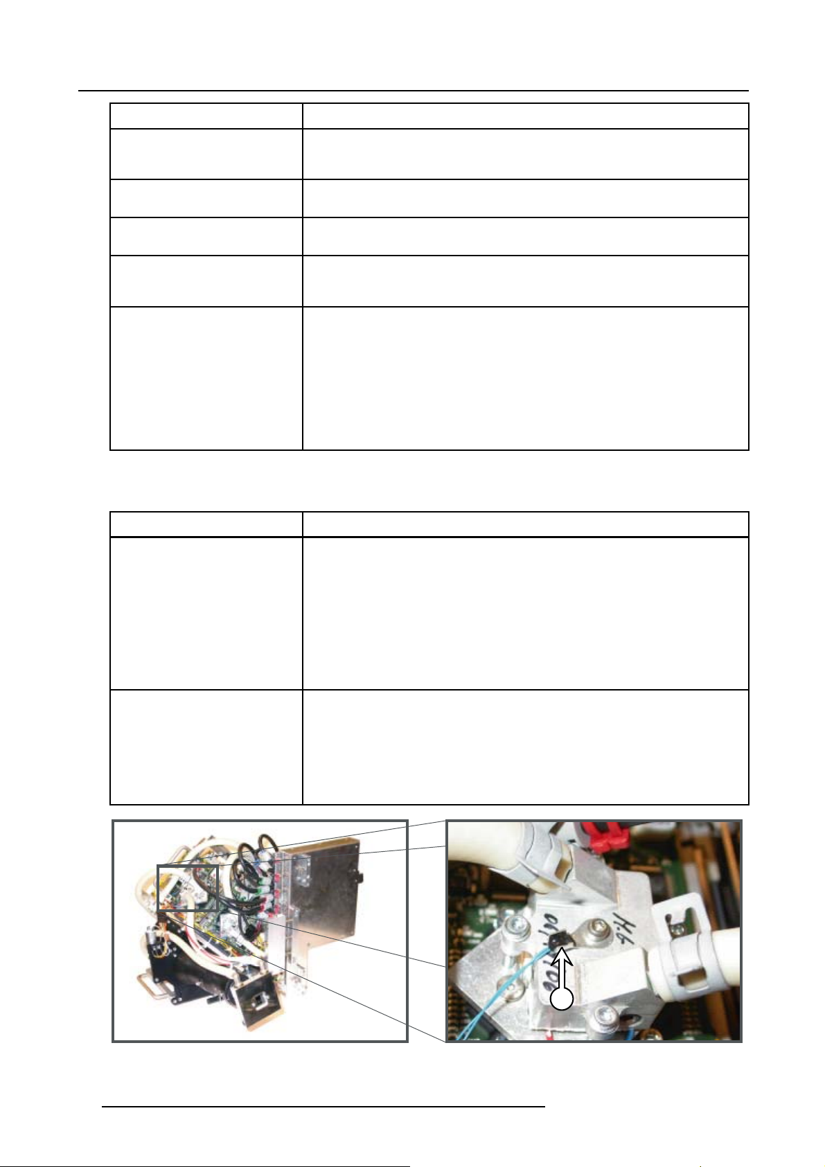
R764240K Projector tilt switch
R848914K
Description FLM R20+ FLM HD18 FLM HD14
Signal distribution board
Start pulse generator
Switched mode power supply
LCD panel 160x80 6H$LED BL
Mains switch 35A UL/CSA
Motor DC 12V D17 + 134:1
Motor DC 12V D17 + 134:1
Carry handle (without parts for top mounting)
x x x
x x x
x x x
x x x
x x x
x x x
x x x
x x x
x x x
x x x
14 R59770072 FLM SERIES 19/03/2007
Page 17

3. Troubleshooting
3. TROUBLESHOOTING
About this chapter
This chapter enumerates all possible error codes which can appear on the local LCD display of the FLM projector. The code displayed is preceded by a “-”signincaseofawarning or a “+”signincaseofarealerror. Note that not all codes have a warning
and an error state. Some only have an error state, others have only a warning state. In case of a “warning” the projector remains
to operate. Nevertheless, it is recommended to solve the problem which causing the “warning” as soon as possible otherwise, the
“warning” state may turn into an “error” state which will switch off the projector consequently.
The codes are placed in ascending order to make it easier to look up the code and find an appropriate solution.
Overview
• 1000 → 1017 : Lamp parameters related errors
• 1692 → 1699 : Formatter related errors
• 2000 → 2808 : Lamp Power Supply (LPS) related errors
• 4000 : Incompatible hardware error
• 4198 : Pixel map related error
• 5095 → 5098 : Flash memory related errors
• 7658 → 7999 : Temperature, fan & motor related errors
• 8000 → 8001: Shutter related errors
• 8002 : Lamp EEPROM error
• 9198 → 9398: CPU related errors
• 10498 : Input module related error
R59770072 FLM SERIES 19/03/2007
15
Page 18

3. Troubleshooting
3.1 1000 → 1017 : Lamp parameters related errors
Error 1000 → 1017 : “Wrong lamp parameters”
These error codes may appear during the start up of the projector.
Situation Solution
Wrong lamp house detected in lamp
compartment of the projector.
No communication with the lamp
house.
A
Replace the lamp house with a compatible lamp house for this projector. Note that a 3,5
kW lamp is not suitable for the FLM R20+ or FLM HD14.
• Check if the blue socket (ref A image 3-1) of the lamp house is not damaged.
Warning: Never attempt to repair the lamp house. Reinstall a new lamp house and
send the damaged lamp house back to factory for repair.
• Check if the blue socket (ref B image 3-1) in the upper left corner of the lamp
compartment is not damaged.
• Check the wiring at the rear side of the blue socket (ref C image 3-2) inside the
projector. The rear side of the blue socket in the projector is visible after removal of
the left side cover (light processor side).
• Check if the wire unit coming from the blue socket in the lamp compartment
is plugged into its socket (ref D image 3-2) on the backplane behind the input
& communication unit.
B
Image 3-1
Image 3-2
D
C
16 R59770072 FLM SERIES 19/03/2007
Page 19

3.2 1692 → 1699 : Formatter related errors
Error 1692 : “Form. PWRGood”
Situation Solution
3. Troubleshooting
Formatter “Power Good" signal not
OK. The local power supplies on
the Formatter Interface Board fails.
The orange LED “PWRGood” (ref
Aimage3-3&image3-4)onthe
Formatter Interface Board remains
off.
The status LED’s of the Formatter
Interface Board (FIB) are visible
through the filter grid behind the
front filter. So, you have to remove
the projector front cover and the
front filter first to see the LED’s on
the FIB.
B
C
FLM
• Check if all wire units between the Formatter Interface Board and the three
formatter boards are not damaged. A damaged wire unit can cause a short circuit
in the local power supply of the Formatter Interface Board.
• Check if none of the pins of the connectors on the FIB or formatter boards are
bend over.
• Replace the Formatter Interface Board.
• If the problem remains contact Barco for further instructions. The formatter boards
are malfunctioning and have to be replaced at the factory.
A
A
B1 B2 B3 B4
Image 3-3
Status LED’s of the Formatter Interface Board (non HD version). Visible trough the grid behind the front filter.
A Orange LED “PWRGood” OK.
B1 Green LED “+5V”.
B2 Green LED “+3.3V”.
B3 Green LED “+2.5V”.
B4 Green LED “+2.1V”.
C Green LED “FPGA DONE”.
R59770072 FLM SERIES 19/03/2007
17
Page 20

3. Troubleshooting
C
B
A
FLM HD
Image 3-4
Status LED’s of the Formatter Interface Board (HD version). Visible trough the grid behind
the front filter.
A Orange LED “PWRGood” OK.
B PowerGood status: LED color = Green “High”; Yellow “Low”;
Red “Fail”.
C FPGA status: LED color = Green “Normal”; Yellow “Boot”; Red
“Fail”.
Error 1693 : “Blue form. start failed”
Situation Solution
No communication with the
tter board of the blue channel.
forma
The projector fails to start.
• Check if the data cables between the Formatter Interface Board (FIB) and the
formatter board of the blue channel are plugged in properly.
• Check if none of the wires came loose from the plugs on the wire unit.
• Reboot the projector. If the problem remains contact Barco for further instructions.
The formatter board of the blue channel is malfunctioning and has to be replaced
he factory.
at t
FLM FLM HD
Image 3-5
Formatter board with data cables plugged in. Two data cables for FLM and three data cables for FLM HD per formatter board.
18 R59770072 FLM SERIES 19/03/2007
Page 21

Error 1694 : “Green form. start failed”
Situation Solution
3. Troubleshooting
No communication with the
formatter board of the green
channel. The projector fails to start.
• Check if both wire units between the Formatter Interface Board (FIB) and the
formatter board of the green channel are plugged in properly.
• Check if none of the wires came loose from the plugs on the wire unit.
• Reboot the projector. If the problem remains contact Barco for further instructions.
The formatter board of the green channel is malfunctioning and has to be replaced
at the factory.
Error 1695 : “Red form. start failed”
Situation Solution
No communication with the
formatter board of the red channel.
The projector fails to start.
• Check if both wire units between the Formatter Interface Board (FIB) and the
formatter board of the red channel are plugged in properly.
• Check if none of the wires came loose from the plugs on the wire unit.
• Reboot the projector. If the problem remains contact Barco for further instructions.
The formatter board of the red channel is malfunctioning and has to be replaced
at the factory.
Error 1696 : “Formatter ctrl init failed”
Situation Solution
The Formatter Interface Board
failed to initialize. The orange LED
“PWRGood” lights up. The green
status LED “FPGA DONE” on the
Formatter Interface Board remains
off (image 3-3 & image 3-4).
The local power supplies on the
Formatter Interface Board fails. The
orange LED “PWRGood” remains
off (image 3-3 & image 3-4).
The Formatter Interface Board has
no power. All status LED’s on the
Formatter Interface Board remains
off while the status LED “+5V FIB”
(image 3-6) on the Fan & Motor
Control Board lights up.
To see the status LED’s of the Fan
& Motor Control Board you have to
remove the projector input cover.
The Formatter Interface Board has
no power. All status LED’s on the
Formatter Interface Board remains
off and the status LED “+5V FIB”
(image 3-6)on the Fan & Motor
Control Board remains off as well.
To see the status LED’s of the Fan
& Motor Control Board you have to
remove the projector input cover.
• Try to reload the flash software of the Formatter Interface Board.
• Check if the Formatter Interface Board is inserted well.
• If the problem remains replace the Formatter Interface Board.
Replace the Formatter Interface Board.
Replace the Formatter Interface Board.
• Check if the Formatter Interface Board is well inserted.
• Replace the Fan & Motor Control Board.
R59770072 FLM SERIES 19/03/2007 19
Page 22

3. Troubleshooting
L2 L4 L6
L1 L3 L5 L7
Image 3-6
Status LED’s of the Fan & Motor Control Board. Located behind the input cover.
L1 Green LED “+30V”.
L2 Green LED “+VMTR”.
L3 Green LED “+VTEC”.
L4 Green LED “++5V”.
L5 Green LED “+5V FIB”.
L6 Green LED “+5V PMP”.
L7 Red LED “ ERROR”.
Error 1697 : “Formatter init failed”
Situation Solution
The projected image is missing
one of the three base colors (red,
green or blue). which indicates that
there is no communication with
the formatter board of the missing
color. You can verify this situation
by activating the internal service
patterns of the formatter boards.
The internal pattern of the involved
channel fails while the others works
fine.
No image can be projected. None
of he internal service patterns of the
formatter board of the red, green
or blue channel can be projected.
The green LED “FPGA DONE” (ref.
C image 3-3 & image 3-4) on the
Formatter Interface Board rema
off while the other status LED’s of
the Formatter Interface Board light
up.
• Check if both wire units between the Formatter Interface Board (FIB) and the
involved formatter board are plugged in properly.
• Reboot the projector. If the problem remains contact Barco for further instructions.
The formatter board of the involved channel is malfunctioning and has to be
replaced at the factory.
• Check if all wire units between the Formatter Interface Board and the three
formatter boards are plugged in prope
• Check the “Error logging”. In case the logging indicates an error with one of the
formatter boards, send the light processor back to factory to replace the involved
ins
formatter board.
• Try to reload the flash software of the Formatter Interface Board.
• If the problem remains, replace the Formatter Interface Board.
rly.
20 R59770072 FLM SERIES 19/03/2007
Page 23

3.3 2000 → 2808 : Lamp Power Supply (LPS) related errors
See also chapter "LPS diagnostic LED’s", page 299, for more diagnostic information about the LPS unit.
Error 2000 : “No LPS detected”
Situation Solution
3. Troubleshooting
No communication with the Lamp
Power Supply.
A C
Image 3-7
A LPS address wire unit.
C LPS control wire unit.
G LPS grey wire unit.
• Check if the grey wire unit (ref G image 3-7) at the rear side of the projector is
connected properly with the “CTRL IN” socket of the LPS module.
• Check if the address wire unit (ref A image 3-7) is plugged in between the LPS units.
• Check if the wire unit (ref H image 3-8) is plugged into its socket on the backplane
behind the “Input and communication unit”
• Check if the pins of the sockets of the SMPS and/or Fan & Motor control board
are not damaged or bend over.
A
C
G
H
Image 3-8
H LPS grey wire unit.
R59770072 FLM SERIES 19/03/2007
21
Page 24

3. Troubleshooting
Error 2001 : “Mains voltage to low”
Situation Solution
The mains voltage applied to the
“MAINS INPUT” sockets of the LPS
module is to low.
Image 3-9
• Check if the main power cables (image 3-9) are connected with the “MAINS
INPUT” sockets of the LPS module.
• Check if the mains voltage applied to the projector power socket is between 200
and 240 VAC.
• Make sure that the electrical dimensions of the extension leads to the projector
meet the power requirements of the projector.
Error 2002 : “Lamp start failed”
The Lamp Power Supply succeeded in igniting the lamp but shortly after ignition the lamp goes out.
Situation Solution
Hot restrike of the lamp. The lamp
fails to illuminate when switched on
shortly after the lamp was switched
off.
Lamp with many strikes, maximum
run time exceeded. The Lamp
Power Supply and the Start Pulse
Generator are working normally.
Nevertheless, the lamp fails to
illuminate.
Malfunction SPG unit. You can not
hear the SPG module three times
clicking in an attempt to ignite the
lamp. The voltage on the “LAMP
OUT” pins of the LPS module is first
140 volt during the attempt to ignite
and then drops to 0 volt after a few
minutes.
Note: The ambient noise must be
low to hear the SPG clicking in an
attempt to ignite the lamp.
Let cool down the lamp for at least 3 minutes before switching the projector from
standby to operating mode.
Replace the exhausted lamp with a new one.
• Check the cabling of the SPG module.
• Replace the SPG module.
Error 2004 : “Lamp goes out”
Situation Solution
Exhausted lamp. Lamp with
many strikes, maximum run time
exceeded.
Replace the exhausted lamp with a new one.
22 R59770072 FLM SERIES 19/03/2007
Page 25

Error 2005 : “Lamp stop failed”
Situation Solution
3. Troubleshooting
No communication with the Lamp
Power Supply.
• Switch off the projector.
• Reboot the projector. If problem remains, replace the Lamp Power Supply.
Error 2006 : “One LPS down, reduced power”
This is not a real error but a warning. The projector will continue to operate.
Situation Solution
Main power cable disconnected
from one of the LPS units
Disconnected wire unit between
the “CTRL IN” and “CTRL OUT”
sockets of the LPS units.
Malfunctioning of one of the LPS
units. The red LED “ERR” of the
malfunctioning LPS unit flashes
fast.
Check if the main power cable is connected with the “MAINS INPUT” socket of the
LPS unit (image 3-9).
Reconnect the wire unit between the “CTRL IN” and “CTRL OUT” sockets of the LPS
units (image 3-7).
Replace the LPS module.
Error 2201 : “PFC start failed”
This error is generated by the LPS unit with address 0x20.
Situation Solution
The power factor corrector of one of
the LPS units fails to start.
Replace the LPS module.
Error 2202 : “LPS start failed”
This error is generated by the LPS unit with address 0x20.
Situation Solution
One of the LPS units fails to start. Replace the LPS module.
Error 2203 : “BOOST start failed”
This error is generated by the LPS unit with address 0x20.
Situation Solution
One of the LPS units fails to place
the start up voltage of 140 volt,
which is required to trigger the SPG,
on the “LAMP OUT” pins of the LPS
unit.
Replace the LPS module.
Error 2206 : “Lamp ignition failed”
This error is generated by the LPS unit with address 0x20.
R59770072 FLM SERIES 19/03/2007
23
Page 26

3. Troubleshooting
Situation Solution
You can hear the SPG module three
times clicking in an attempt to ignite
the lamp. The voltage on the “LAMP
OUT” pins of the LPS module is first
140 volt during the attempt to ignite
and then drops to 0 volt after a few
minutes.
Note: The ambient noise must be
low to hear the SPG clicking in an
attempt to ignite the lamp.
You can not hear the SPG module
three times clicking in an attempt
to ignite the lamp. The voltage on
the “LAMP OUT” pins of the LPS
module is first 140 volt during the
attempt to ignite and then drops to
0 volt after a few minutes.
Note: The ambient noise must be
low to hear the SPG clicking in an
attempt to ignite the lamp.
You can not hear the SPG module
three times clicking in an attempt
to ignite the lamp. The voltage on
the “LAMP OUT” pins of the LPS
module is below 140 volt during the
attempt to ignite. The diagnostic
LED’s of the LPS module indicates
a problem with the LPS module.
Note: The ambient noise must be
low to hear the SPG clicking in an
attempt to ignite the lamp.
• The LPS and SPG seem the work normally but the lamp is exhausted. Install
a new lamp.
• If the problem remains, replace the SPG module.
• Check the cabling of the SPG module.
• Replace the SPG module.
• Check the cabling of the LPS module.
• Replace the LPS module.
Error 2207 : “Lamp voltage range”
s error is generated by the LPS unit with address 0x20.
Thi
Situation Solution
AMP OUT” voltage of the
The “L
lamp power supply is out of range.
•Reb
• If problem remains, replace the LPS module.
oot the projector.
Error 2208 : “Lamp power range”
This error is generated by the LPS unit with address 0x20.
Situation Solution
The power delivered by the lamp
power supply is out of range.
• Reboot the projector.
• If problem remains, replace the LPS module.
Error 2501 : “PFC start failed”
The same troubleshooting checklist can be applied to as for Error 2201. The only difference is that this error is generated by the
LPS unit with address 0x22.
Error 2502 : “LPS start failed”
The same troubleshooting checklist can be applied to as for Error 2202. The only difference is that this error is generated by the
LPS unit with address 0x22.
Error 2503 : “BOOST start failed”
The same troubleshooting checklist can be applied to as for Error 2203. The only difference is that this error is generated by the
LPS unit with address 0x22.
24
R59770072 FLM SERIES 19/03/2007
Page 27

3. Troubleshooting
Error 2506 : “Lamp ignition failed”
The same troubleshooting checklist can be applied to as for Error 2206. The only difference is that this error is generated by the
LPS unit with address 0x22.
Error 2507 : “Lamp voltage range”
The same troubleshooting checklist can be applied to as for Error 2207. The only difference is that this error is generated by the
LPS unit with address 0x22.
Error 2508 : “Lamp power range”
The same troubleshooting checklist can be applied to as for Error 2208. The only difference is that this error is generated by the
LPS unit with address 0x22.
Error 2801 : “PFC start failed”
The same troubleshooting checklist can be applied to as for Error 2201. The only difference is that this error is generated b
LPS unit with address 0x28.
ythe
Error 2802 : “LPS start failed”
The same troubleshooting checklist can be applied to as for Error 2202. The only difference is that this error is generated by the
LPS unit with address 0x28.
Error 2803 : “BOOST start failed”
The same troubleshooting checklist can be applied to as for Error 2203. The only diffe
LPS unit with address 0x28.
rence is that this error is generated by the
Error 2806 : “Lamp ignition failed”
The same troubleshooting checklist can be applied to as for Error 2206. The only difference is that this error is generated by the
LPS unit with address 0x28.
Error 2807 : “Lamp voltage range”
The same troubleshooting checklist can be applied to as for Error 2207.
LPS unit with address 0x28
The only difference is that this error is generated by the
Error 2808 : “Lamp power range”
The same troubleshooting checklist can be applied to as for Error 2208. The only difference is that this error is generated by the
LPS unit with address 0x28.
R59770072 FLM SERIES 19/03/2007
25
Page 28

3. Troubleshooting
3.4 4000 : Incompatible hardware error
Error 4000 : “Incompatible hardware”
Situation Solution
One or more parts of the projector
are replaced with incompatible
parts.
I2C related error. One of the boards
with an I
hardware error.
2
C address causes a
• Reinstall the original parts of the projector. Use only original Barco spare parts
for servicing.
• If the problem persists, contact Barco for further instructions.
• Check the I2C status of the boards via the user interface: Service >
Diagnoses > I
• If the problem persists, contact Barco for further instructions.
2
C and replace the malfunction board.
26 R59770072 FLM SERIES 19/03/2007
Page 29

3.5 4198 : Pixel map related error
Error 4198 : “FPGA-PMP init failed”
Situation Solution
3. Troubleshooting
The controller was unable to
initialize the FPGA of the Pixel Map
Processor (PMP).
• Reboot the projector.
• If the problem persists, reinstall the PMP firmware using the Projector Toolset.
• If the problem persists, replace the PMP.
R59770072 FLM SERIES 19/03/2007 27
Page 30

3. Troubleshooting
3.6 5095 → 5098 : Flash memory related errors
Error 5095 : “Restoring unsuccessful”
Situation Solution
Restoring the custom settings from
the internal backup device has
failed.
• Check if the latest projector software is installed.
• Reinstall the latest projector software.
• If the problem persists, contact Barco for further instructions.
Error 5096 : “Storing unsuccessful”
Situation Solution
Storing the custom settings from the
internal backup device has failed.
• Check if the latest projector software i
• Reinstall the latest projector software.
• If the problem persists, contact Barco for further instructions.
Error 5097 : “Flash management full”
Situation Solution
The reserved memory for flash
management has reached its limits.
• Check if the latest projector software is installed.
• Delete some unnecessary custom made image files.
• Delete some unnecessary custom made layout files.
• If the problem persists, contact Barco for further instructions.
Error 5098 : “Flash full”
Situation Solution
s installed.
Internal backup device has reached
its maximum capacity.
• Check if the latest projector software is installed.
• Delete some unnecessary custom made image files.
• Delete some unnecessary custom made layout files.
• If the problem persists, contact Barco for further instructions.
28 R59770072 FLM SERIES 19/03/2007
Page 31

3.7 7658 → 7999 : Temperature, fan & motor related errors
Error 7658 : “Engine air temp short”
This error may be preceded by a warning. This error can only appear on the FLM HD series.
Situation Solution
3. Troubleshooting
Damaged insulation of the wire unit
of the temperature sensor (ref E
image 3-10), which measures the
temperature inside the compartment
of the light processor. When
disconnecting the wire unit (ref E
image 3-11) of the temperature
sensor from the Formatter Interface
Board the error code is changed to
7659 : “Engine air temp open”.
Defect temperature sensor (ref E
image 3-10) of the light processor.
When disconnecting the wire
unit (ref E image 3-11) of the
temperature sensor from the
Formatter Interface Board (FIB) the
error code is changed to 7659 :
“Engine air temp open”.
Damaged socket (ref E image 3-10)
on the FIB.
• Repair the insulation of the wire unit using shrink sleeve.
• If not repairable, replace the whole wire unit and temperature sensor.
Replace the temperature sensor.
Check if no pins are bent over of the socket for the wire unit of the temperature sensor
(E).
Image 3-10
E Engine air temperature sense.
E
R59770072 FLM SERIES 19/03/2007
29
Page 32

3. Troubleshooting
R G B
BL
FR
TB
TG
TR
Image 3-11
Sockets on the Formatter Interface Board (FIB) of the FLM HD series
R Temperature sense Red channel.
G Temperature sense Green channel.
B Temperature sense Blue channel.
BL Temperature sense DMD water cooling blocks.
FR Temperature sense DMD front.
E Temperature sense light processor air (Engine).
H Temperature sense Heat pipes cooling block.
TB Power supply for TEC front blue.
TG Power supply for TEC front green.
TR Power supply for TEC front red.
Error 7659 : “Engine air temp open”
This error may be preceded by a warning. This error can only appear on the FLM HD series.
Situation Solution
E
H
Wire unit of the temperature sensor
(ref E image 3-10) is disconnected
from the Formatter Interface Board.
Damaged wire unit of the
temperature sensor (ref E
image 3-10) causing an open
circuit.
Defect temperature sensor (ref E
image 3-10) of the light processor.
Plug the wire unit of the temperature sensor (E) into its socket on the Formatter
Interface Board. See image 3-11.
• Repair the wire unit.
• If not repairable, replace the hole wire unit and temperature sensor.
Replace the temperature sensor.
Error 7660 : “Engine air temp high”
This error may be preceded by a warning. This error can only appear on the FLM HD series.
Situation Solution
Air temperature inside the
compartment of the light processor
is to high.
• Check if the air inlet at the front and at the bottom of the projector are free.
• Check if the bottom filter of the projector is not filthy. Replace with new filter
if necessary.
• Check if the front filter of the projector is not filthy. Replace with new filter if
necessary.
• Check if the air outlet at the rear of the projector is not covered. There should be at
least one meter of free area at the rear of the projector.
• Make sure that the plate, on which the projector is mounted for transport, is
removed.
Error 7662 : “Blue block temp short”
This error may be preceded by a warning. This error can only appear on the FLM HD series.
30
R59770072 FLM SERIES 19/03/2007
Page 33

Situation Solution
3. Troubleshooting
Damaged insulation of the wire unit
of the temperature sensor (ref B
image 3-12), which measures the
temperature of the water cooling
block of the blue channel. When
disconnecting the wire unit (ref B/BL
image 3-11) of the temperature
sensor from the Formatter Interface
Board (FIB) the error code is
changed to 7663 : “Blue block temp
open”.
Defect temperature sensor on the
water cooling block of the blue
channel. When disconnecting the
wire unit of the temperature sensor
from the Formatter Interface Board
(FIB) the error code is changed to
7663 : “Blue block temp open”.
• Repair the insulation of the wire unit using shrink sleeve.
• If not repairable, replace the whole wire unit and temperature sensor.
Replace the temperature sensor.
B
Image 3-12
B Temperature sensor DMD cooling block blue channel.
Error 7663 : “Blue block temp open”
This error may be preceded by a warning. This error can only appear on the FLM HD series.
Situation Solution
Wire unit (ref B/BL image 3-11)
of the temperature sensor is
disconnected from the Formatter
Interface Board (FIB)
Damaged wire unit of the
temperature sensor (ref B
image 3-12) which measures
the temperature of the water cooling
block of the blue channel.
Defect temperature sensor (ref B
image 3-12) on the water cooling
block of the blue channel.
Error 7664 : “Blue block temp high”
This error may be preceded by a warning. This error can only appear on the FLM HD series. Temperature of the water cooling block
of the blue channel is to high. If this problem persist the projector will shut down the lamp.
Plug in the wire unit of the temperature sensor into its socket on the Formatter Interface
Board.
• Repair the wire unit.
• If not repairable, replace the hole wi
Replace the temperature sensor.
re unit and temperature sensor.
R59770072 FLM SERIES 19/03/2007
31
Page 34

3. Troubleshooting
Situation Solution
Interruption of the liquid cooling
circuit.
The liquid cooling circuit of the light
processor is mistakenly excluded
from the main liquid cooling circuit.
Water cooling pump electrical
disconnected.
Blocked high density filter of the
heat exchanger.
No or insufficient liquid inside the
cooling circuit. The pump is sucking
air and sounds noisier then normal.
Malfunction pump of the water
cooling circuit. You don’t feel any
vibrations when touching the pump
after activating the “Refill mode” via
the user interface:
Service > Refill mode >
Yes
Note: to exit the “Refill mode” you
have to switch off the projector.
Check if the loop of the liquid cooling circuit is closed.
Reconnect the cooling circuit of the light processor with the pump and heat exchanger.
Check if the wire unit (ref C image 3-13) of the pump is properly connected.
Replace the blocked high density filter with a new one.
Fill the cooling circuit with liquid and expel all air. Pressurize the circuit. See "FLM
liquid cooling circuit", page 153.
• Check the electrical resistance of the pump’s winding. Replace the pump if infinite.
See "Cooling pump replacement", page 197.
• Drain the liquid cooling circuit, open the pump and check if the pump is not blocked.
If so, remove the rotor (ref R image 3-13) and clean the bearings of the pump. See
"Maintaining the cooling pump", page 190.
P
C
Image 3-13
P Pump liquid cooling circuit.
C Electrical connection pump.
R Rotor of pump.
Error 7666 : “Green block temp short”
This error may be preceded by a warning. This error can only appear on the FLM HD series.
R
32
R59770072 FLM SERIES 19/03/2007
Page 35

Situation Solution
3. Troubleshooting
Damaged insulation of the wire unit
of the temperature sensor (ref G
image 3-14), which measures the
temperature of the water cooling
block of the green channel. When
disconnecting the wire unit (ref G/BL
image 3-11) of the temperature
sensor from the Formatter Interface
Board (FIB) the error code is
changed to 7667 : “Green block
temp open”.
Defect temperature sensor on the
water cooling block of the green
channel. When disconnecting the
wire unit of the temperature sensor
from the Formatter Interface Board
(FIB) the error code is changed to
7667 : “Green block temp open”.
• Repair the insulation of the wire unit using shrink sleeve.
• If not repairable, replace the whole wire unit and temperature sensor.
Replace the temperature sensor.
G
Image 3-14
Error 7667 : “Green block temp open”
This error may be preceded by a warning. This error can only appear on the FLM HD series.
Situation Solution
Wire unit (ref G/BL image 3-11)
of the temperature sensor is
disconnected from the Formatter
Interface Board (FIB)
Damaged wire unit of the
temperature sensor (ref B
image 3-14) which measures
the temperature of the water cooling
block of the green channel.
Defect temperature sensor (ref B
image 3-14) on the water cooling
block of the green channel.
Plug in the wire unit of the temperature sensor into its socket on the Formatter Interface
Board.
• Repair the wire unit.
• If not repairable, replace the hole wire unit and temperature sensor.
Replace the temperature sensor.
Error 7668 : “Green block temp high”
This error may be preceded by a warning. This error can only appear on the FLM HD series. Temperature of the water cooling block
of the green channel is to high. If this problem persist the projector will shut down the lamp.
Situation Solution
Interruption of the liquid cooling
circuit.
Check if the loop of the liquid cooling circuit is closed.
R59770072 FLM SERIES 19/03/2007 33
Page 36
3. Troubleshooting
Situation Solution
The liquid cooling circuit of the light
processor is mistakenly excluded
from the main liquid cooling circuit.
Water cooling pump electrical
disconnected.
Blocked high density filter of the
heat exchanger.
No or insufficient liquid inside the
cooling circuit. The pump is sucking
air and sounds noisier then normal.
Malfunction pump of the water
cooling circuit. You don’t feel any
vibrations when touching the pump
after activating the “Refill mode” via
the user interface:
Service > Refill mode >
Yes
Note: to exit the “Refill mode” you
have to switch off the projector.
Reconnect the cooling circuit of the light processor with the pump and heat exchanger.
Check if the wire unit (ref C image 3-13) of the pump is properly connected.
Replace the blocked high density filter with a new one.
Fill the cooling circuit with liquid and expel all air. Pressurize the circuit. See "FLM
liquid cooling circuit", page 153.
• Check the electrical resistance of the pump’s winding. Replace the pump if infinite.
See "Cooling pump replacement", page 197.
• Drain the liquid cooling circuit, open the pump and check if the pump is not blocked.
If so, remove the rotor (ref R image 3-13) and clean the bearings of the pump. See
"Maintaining the cooling pump", page 190.
Error 7670 : “Red block temp short”
This error may be preceded by a warning. This error can only appear on the FLM HD series.
Situation Solution
Damaged insulation of the wire unit
of the temperature sensor (ref R
image 3-15), which measures the
temperature of the water cooling
block of the red channel. When
disconnecting the wire unit (ref R/BL
image 3-11) of the temperature
sensor from the Formatter Interface
Board (FIB) the error code is
changed to 7671 : “Red block temp
open”.
Defect temperature sensor (ref R
image 3-15) on the water cooling
block of the red channel. When
disconnecting the wire unit of
the temperature sensor from the
Formatter Interface Board (FIB) the
error code is changed to 7671 :
“Red block temp open”.
• Repair the insulation of the wire unit using shrink sleeve.
• If not repairable, replac
Replace the temperature sensor.
e the whole wire unit and temperature sensor.
R
Image 3-15
34 R59770072 FLM SERIES 19/03/2007
Page 37

Error 7671 : “Red block temp open”
This error may be preceded by a warning. This error can only appear on the FLM HD series.
Situation Solution
3. Troubleshooting
Wire unit (ref R/BL image 3-11)
of the temperature sensor is
disconnected from the Formatter
Interface Board (FIB)
Damaged wire unit of the
temperature sensor (ref R
image 3-15) which measures
the temperature of the water cooling
block of the red channel.
Defect temperature sensor (ref R
image 3-15) on the water cooling
block of the red channel.
Plug in the wire unit of the temperature sensor into its socket on the Formatter Interface
Board.
• Repair the wire unit.
• If not repairable, replace the hole wire unit and temperature sensor.
Replace the temperature sensor.
Error 7672 : “Red block temp high”
This error may be preceded by a w
of the red channel is to high. If this problem persist the projector will shut down the lamp.
Situation Solution
Interruption of the liquid cooling
circuit.
The liquid cooling circuit
processor is mistakenly excluded
from the main liquid cooling circuit.
Water cooling pump electrical
disconnected.
arning. This error can only appear on the FLM HD series. Temperature of the water cooling block
Check if the loop of the liquid cooling circuit is closed.
of the light
Reconnect the cooling circ
Check if the wire unit (
uit of the light processor with the pump and heat exchanger.
ref C image 3-13) of the pump is properly connected.
Blocked high density filter of the
heat exchanger.
No or insufficient l
cooling circuit. The pump is sucking
air and sounds noisier then normal.
Malfunction pump o
cooling circuit. You don’t feel any
vibrations when touching the pump
after activat
the user interface:
Service > Refill mode >
Yes
Note: to exi
have to switch off the projector.
iquid inside the
fthewater
ing the “Refill mode” via
t the “Refill mode” you
Replace the blocked high density filter with a new one.
Fill the cooling cir
liquid cooling circuit", page 153.
• Check the electrical resistance of the pump’s winding. Replace the pump if infinite.
See "Cooling pump replacement", page 197.
• Drain the liquid cooling circuit, open the pump and check if the pump is not blocked.
If so, remove the rotor (ref R image 3-13) and clean the bearings of the pump. See
"Maintaining the cooling pump", page 190.
cuit with liquid and expel all air. Pressurize the circuit. See "FLM
Error 7674 : “Front block temp short”
This error may be preceded by a warning. This error can only appear on the FLM HD series.
R59770072 FLM SERIES 19/03/2007
35
Page 38

3. Troubleshooting
Situation Solution
Damaged insulation of the wire
unit of the temperature sensor (ref
H image 3-16), which measures
the temperature of the common
water cooling block of the heat
pipes. When disconnecting the
wire unit (ref H image 3-11) of
the temperature sensor from the
Formatter Interface Board (FIB) the
error code is changed to 7675 :
“Front block temp open”.
Defect temperature sensor (ref
H image 3-16) on the common
water cooling block of the heat
pipes. When disconnecting the
wire unit (ref H image 3-11) of
the temperature sensor from the
Formatter Interface Board (FIB) the
error code is changed to 7675 :
“Front block temp open”.
• Repair the insulation of the wire unit using shrink sleeve.
• If not repairable, replace the light processor. Contact Barco for further instructions
to repair the malfunction light processor.
Replace the light processor. Contact Barco for further instructions to repair the
malfunction light processor.
H
Image 3-16
Error 7675 : “Front block temp open”
This error may be preceded by a warning. This error can only appear on the FLM HD series.
Situation Solution
Wire unit of the temperature sensor
disconnected from the Formatter
Interface Board (FIB)
Damaged wire unit of the
temperature sensor (ref H
image 3-16) which measures
the temperature of the water cooling
block of the red channel.
Defect temperature sensor (ref H
image 3-16) on the water cooling
block of the red channel.
Plug in the wire unit of the temperature sensor into its socket on the Formatter Interface
Board.
• Repair the wire unit.
• If not repairable, replace the light p
to repair the malfunction light processor.
Replace the light processor. Contact Barco for further instructions to repair the
malfunction light processor.
rocessor. Contact Barco for further instructions
Error 7676 : “Front block temp high”
This error may be preceded by a warning. This error can only appear on the FLM HD series.
Situation Solution
Interruption of the liquid cooling
circuit.
Check if the loop of the liquid cooling circuit is closed.
36 R59770072 FLM SERIES 19/03/2007
Page 39

Situation Solution
3. Troubleshooting
The liquid cooling circuit of the light
processor is mistakenly excluded
from the main liquid cooling circuit.
Water cooling pump electrical
disconnected.
Blocked high density filter of the
heat exchanger.
No or insufficient liquid inside the
cooling circuit. The pump is sucking
air and sounds noisier then normal.
Malfunction pump of the water
cooling circuit. You don’t feel any
vibrations when touching the pump
after activating the “Refill mode” via
the user interface:
Service > Refill mode >
Yes
Note: to exit the “Refill mode” you
have to switch off the projector.
Reconnect the cooling circuit of the light processor with the pump and heat exchanger.
Check if the wire unit (ref C image 3-13) of the pump is properly connected.
Replace the blocked high density filter with a new one.
Fill the cooling circuit with liquid and expel all air. Pressurize the circuit. See "FLM
liquid cooling circuit", page 153.
• Check the electrical resistance of the pump’s winding. Replace the pump if infinite.
See "Cooling pump replacement", page 197.
• Drain the liquid cooling circuit, open the pump and check if the pump is not blocked.
If so, remove the rotor (ref R image 3-13) and clean the bearings of the pump. See
"Maintaining the cooling pump", page 190.
Error 7684 : “Blue front DMD temp short”
This error may be preceded by a warning. This error can only appear on the FLM HD series. Note that the FLM HD series have
three temperature sensors per channel. The first sensor (A) is visible on top of the cooling block, the second sensor (C) fits between
the thermoelectric cooler (B) and DMD and the third sensor (D) is located at the front of the DMD. The illustration below shows the
temperature sensors or the wire units leading to the sensors for the red channel. Nevertheless, the sensors for the red and green
channel are in the same manner positioned.
A
B
C
Image 3-17
A Temperature sensor on the cooling block of the blue channel.
B TEC (Thermoelectric cooler) located between DMD and cooling block.
C Wire unit leading to the temperature sensor at the back side of the DMD.
D Wire unit leading to the temperature sensor at the front of the DMD
D
R59770072 FLM SERIES 19/03/2007
37
Page 40

3. Troubleshooting
Situation Solution
Damaged insulation of the wire
unit of the temperature sensor (ref
D image 3-17) which measures
the temperature at the front of the
DMD of the blue channel. When
disconnecting the wire unit (ref B/FR
image 3-11) of the temperature
sensor from the Formatter Interface
Board (FIB) the error code is
changed to 7685 : “Blue front DMD
temp open”.
Defect temperature sensor which
measures the temperature at the
front of the DMD of the blue channel.
• Repair the insulation of the wire unit using shrink sleeve.
• If not repairable, replace the light processor. Contact Barco for further instructions
to repair the malfunction light processor.
Replace the light processor. Contact Barco for further instructions to repair the
malfunction light processor.
Error 7685 : “Blue front DMD temp open”
This error may be preceded by a warning. This error can only appear on the FLM HD series.
Situation Solution
Wire unit (ref B/FR image 3-11)
of the temperature sensor is
disconnected from the Formatter
Interface Board (FIB)
Damaged wire unit of the
temperature sensor which
measures the temperature at
the front of the DMD of the blue
channel.
Plug in the wire unit of the temperature sensor into its socket on the Formatter Interface
Board. See image 3-11.
• Repair the wire unit.
• If not repairable,
to repair the malfunction light processor.
replace the light processor. Contact Barco for further instructions
Defect temperature sensor which
measures the temperature at the
front of the DMD of the blue channel.
Replace the light processor. Contact Barco for further instructions to repair the
malfunction light processor.
Error 7686 : “Blue front DMD temp high”
This error may be preceded by a warning. This error can only appear on the FLM HD series.
Situation Solution
The wire unit of the temperature
sensor at the front of the DMD is
mistakenly switched with one of the
wire units of the other temperature
sensors of the light processor.
The wire units of the TEC’s (Peltier
element), mounted on the common
cooling block of the heat pipes, are
mistakenly switched.
No thermal contact between heat
pipes and common cooling block
due to loose screws.
Malfunction TEC between heat
pipes and common cooling block.
Use the “diode test” of a multi-meter
to check out the TEC. Polarity
doesn’t matter. The TEC is not
OK in case the measured value is
higher then 0,01 volt.
Check if all wire units of the temperature sensors are plugged into their respective
sockets on the Formatter Interface Board. See image 3-11.
Check if all wire units of the TEC’s for front cooling are plugged into their respective
sockets on the Formatter Interface Board. See image 3-11.
Check if the four screws, which attach the heat pipes of the involved channel to the
common cooling block, are fastened. See image 3-18.
Remove the light processor from its compartment and replace the malfunction TEC.
If problem persist contact Barco for further instructions.
38 R59770072 FLM SERIES 19/03/2007
Page 41

3. Troubleshooting
S
S
S
S
H
Image 3-18
Heat pipes securing screws (e.g. red channel)
S Screws.
H heat pipe.
Error 7687 : “Blue front DMD temp low”
This is a warning. This warning can only appear on the FLM HD series.
Situation Solution
The temperature on the front side of
the DMD of the blue channel is low.
Error 7688 : “Green front DMD temp short”
This error may be preceded by a warning. This error can only appear on the FLM HD series.
If this warning persist, contact Barco for further instructions.
Situation Solution
Damaged insulation of the wire
unit of the temperature sensor (ref
D image 3-17) which measures
the temperature at the front of
the DMD of the green channel.
When disconnecting the wire
unit (ref G/FR image 3-11) of
the temperature sensor from the
Formatter Interface Board (FIB) the
error code is changed to 7689 :
“Green front DMD temp open”.
Defect temperature sensor which
measures the temperature at the
front of the DMD of the green
channel.
• Repair the insulation of the wire unit using shrink sleeve.
• If not repairabl
to repair the malfunction light processor.
Replace the light processor. Contact Barco for further instructions to repair the
malfunction light processor.
e, replace the light processor. Contact Barco for further instructions
Error 7689 : “Green front DMD temp open”
This error may be preceded by a warning. This error can only appear on the FLM HD series.
Situation Solution
Wire unit (ref G/FR image 3-11)
of the temperature sensor is
disconnected from the Formatter
Interface Board (FIB)
Plug in the wire unit of the temperature sensor into its socket on the Formatter Interface
Board. See image 3-11.
R59770072 FLM SERIES 19/03/2007 39
Page 42

3. Troubleshooting
Situation Solution
Damaged wire unit of the
temperature sensor which
measures the temperature at
the front of the DMD of the green
channel.
Defect temperature sensor which
measures the temperature at the
front of the DMD of the green
channel.
Error 7690 : “Green front DMD temp high
This error may be preceded by a warning. This error can only appear on the FLM HD series.
Situation Solution
The wire unit of the temperature
sensor at the front of the DMD is
mistakenly switched with one of the
wire units of the other temperature
sensors of the light processor.
The wire units of the TEC’s (Peltier
element), mounted on the common
cooling block of the heat pipes, are
mistakenly switched.
No thermal contact between heat
pipes of the involved channel and
common cooling block due to loose
screws.
• Repair the wire unit.
• If not repairable, replace the light processor. Contact Barco for further instructions
to repair the malfunction light processor.
Replace the light processor. Contact Barco for further instructions to repair the
malfunction light processor.
”
Check if all wire units of the temperature sensors are plugged into their respective
sockets on the Formatter Interface Board. See image 3-11.
Check if all wire units of the TEC’s are plugged into their respective sockets on the
Formatter Interface Board. See image 3-11.
Check if the four screws, which attach the heat pipes to the common cooling block,
are fastened. See image 3-18.
Malfunction TEC between heat
pipes and common cooling block.
Use the “diode test” of a multi-meter
to check out the TEC. Polarity
doesn’t matter. The TEC is not
OK in case the measured value is
higher then 0,01 volt.
Remove the light processor from its compartment and replace the malfunction TEC.
If problem persist contact Barco for further instructions.
Error 7691 : “Green front DMD temp low”
This is a warning. This warning can only appear on the FLM HD series.
Situation Solution
The temperature on the front side
of the DMD of the green channel is
low.
If this warning persist, contact Barco for further instructions.
Error 7692 : “Red front DMD temp short”
This error may be preceded by a warning. This error can only appear on the FLM HD series.
40
R59770072 FLM SERIES 19/03/2007
Page 43

Situation Solution
3. Troubleshooting
Damaged insulation of the wire
unit of the temperature sensor (ref
D image 3-17) which measures
the temperature at the front of the
DMD of the red channel. When
disconnecting the wire unit (ref R/FR
image 3-11) of the temperature
sensor from the Formatter Interface
Board (FIB) the error code is
changed to 7693 : “Red front DMD
temp open”.
Defect temperature sensor which
measures the temperature at the
front of the DMD of the green
channel.
Error 7693 : “Red fro
This error may be preceded by a warning. This error can only appear on the FLM HD series.
Situation Solution
Wire unit (ref R/FR image 3-11)
of the temperature sensor is
disconnected from the Formatter
Interface Board (FIB)
Damaged wire unit of the
temperature sensor which
measures the temperature at
the front of the DMD of the red
channel.
nt DMD temp open”
• Repair the insulation of the wire unit using shrink sleeve.
• If not repairable, replace the light processor. Contact Barco for further instructions
to repair the malfunction light processor.
Replace the light processor. Contact Barco for further instructions to repair the
malfunction light processor.
Plug in the wire unit of the temperature sensor into its socket on the Formatter Interface
Board. See image 3-11.
• Repair the wire unit.
• If not repairable, replace the light processor. Contact Barco for further instructions
to repair the malfunction light processor.
Defect temperature sensor which
measures the temperature at the
front of the DMD of the red channel.
Replace the light processor. Contact Barco for further instructions to repair the
malfunction light processor.
Error 7694 : “Red front DMD temp high”
This error may be preceded by a warning. This error can only appear on the FLM HD series.
Situation Solution
The wire unit of the temperature
sensor at the front of the DMD is
mistakenly switched with one of the
wire units of the other temperature
sensors of the light processor.
The wire units of the TEC’s (Peltier
element), mounted on the common
cooling block of the heat pipes, are
mistakenly switched.
No thermal contact between heat
pipes of the involved channel and
common cooling block due to loose
screws.
Malfunction TEC between heat
pipes and common cooling block.
Use the “diode test” of a multi-meter
to check out the TEC. Polarity
doesn’t matter. The TEC is not
OK in case the measured value is
higher then 0,01 volt.
Check if all wire units of the temperature sensors are plugged into their respective
sockets on the Formatter Interface Board. See image 3-11.
Check if all wire units of the TEC’s are plugged into their respective sockets on the
Formatter Interface Board. See image 3-11.
Check if the four screws, which attach the heat pipes to the common cooling block,
are fastened. See image 3-18.
Remove the light processor from its compartment and replace the malfunction TEC.
If problem persist contact Barco for further instructions.
Error 7695 : “Red front DMD temp low”
This is a warning. This warning can only appear on the FLM HD series.
R59770072 FLM SERIES 19/03/2007
41
Page 44

3. Troubleshooting
Situation Solution
The temperature on the front side of
the DMD of the red channel is low.
If this warning persist, contact Barco for further instructions.
Error 7696 : “Light pipe temp short”
This error may be preceded by a warning. This error can only appear on the FLM HD series.
Situation Solution
Damaged insulation of the wire unit
of the temperature sensor (ref L
image 3-19) which measures the
temperature of the cooling block
at the light pipe entrance. When
disconnecting the wire unit (ref L
image 3-20) of the temperature
sensor from the Formatter Interface
Board (FIB) the error code is
changed to 7697 : “Light pipe temp
open”.
Defect temperature sensor which
measures the temperature of the
cooling block at the light pipe
entrance.
• Repair the insulation of the wire unit using shrink sleeve.
• If not repairable, replace the whole wire unit and temp
Replace the temperature sensor.
erature sensor.
L
Image 3-19
L Temperature sensor on light pipe entrance.
Error 7697 : “Light pipe temp open”
his error may be preceded by a warning. This error can only appear on the FLM HD series.
T
Situation Solution
e unit of the temperature sensor
Wir
is disconnected from the Formatter
Interface Board (FIB)
maged wire unit of the
Da
temperature sensor (ref L
image 3-19) which measures
the temperature of the cooling block
at the light pipe entrance.
Defect temperature sensor (ref L
image 3-19) on the cooling block at
the light pipe entrance.
42 R59770072 FLM SERIES 19/03/2007
g in the wire unit (ref L image 3-20) of the temperature sensor into its socket on
Plu
the Formatter Interface Board.
• Repair the wire unit.
• If not repairable, replace the hole wire unit and temperature sensor.
Replace the temperature sensor.
Page 45

3. Troubleshooting
SB
L
DB
LS
CA
SH
SG
SR
DG
DR
PR
Image 3-20
SB Wire unit of temperature sensor at the rear of the DMD of the blue channel.
SG Wire unit of temperature sensor at the rear of the DMD of the green channel.
SR Wire unit of temperature sensor at the rear of the DMD of the red channel.
L Wire unit of temperature sensor on the cooling block at the light pipe entrance (HD version only).
CA Wire unit of the cat eye.
SH Wire unit of the shutter.
LS Wire unit of the light sensor inside the light pipe.
PR Wire unit of press sensor on the prism.
DB Wire unit of the TEC of the blue channel.
DG Wire unit of the TEC of the green channel.
DR Wire unit of the TEC of the red channel.
Error 7698 : “Light pipe temp high”
This error may be preceded by a warning. This error can only appear on the FLM HD series.
Situation Solution
Interruption of the liquid cooling
circuit.
The liquid cooling circuit of the light
processor is mistakenly excluded
from the main liquid cooling circuit.
Water cooling pump electrical
disconnected.
Blocked high density filter of the
heat exchanger.
No or insufficient liquid inside the
cooling circuit. The pump is sucking
air and sounds noisier then normal.
Malfunction pump of the water
cooling circuit. You don’t feel any
vibrations when touching the pump
after activating the “Refill mode” via
the user interface:
Service > Refill mode >
Yes
Note: to exit the “Refill mode” you
have to switch off the projector.
Misalignment of the lamp inside the
lamp house.
Check if the loop of the liquid cooling circuit is closed.
Reconnect the cooling circuit of the light processor with the pump and heat exchanger.
Check if the wire unit (ref Cimage 3-13) of the pump is properly connected.
Replace the blocked high density filter with a new one. See chapter "Dust filters",
page 85.
Fill the cooling circuit with liquid and expel all air. Pressurize the circuit. See "FLM
liquid cooling circuit", page 153.
• Check the electrical resistance of the pump’s winding. Replace the pump if infinite.
See "Cooling pump replacement", page 197.
• Draintheliquidcoolingcircuit,ope
If so, remove the rotor (ref R image 3-13) and clean the bearings of the pump. See
"Maintaining the cooling pump", page 190.
• Readjust the Z-alignment of the lamp, see "Realignment of the lamp in its reflector",
page 93.
• Replace lamp house with new lamp house.
n the pump and check if the pump is not blocked.
Misalignment of the cold mirr
or.
Readjust the cold mirror, see "Adjusting the cold mirror", page 127.
Error 7927 : “fan speed mains input too low”
This error may be preceded by a warning.
R59770072 FLM SERIES 19/03/2007
43
Page 46

3. Troubleshooting
Situation Solution
Disconnected wire unit.
Blocked fan. Unblock the fan. Ensure that the fan can turn freely.
Damaged wire unit.
Fan end of life. Replace the fan. See procedure "Replacing the mains input fan", page 268.
Reconnect the wire unit of the fan. Check if the wire unit of the fan is plugged into its
socket on the backplane.
Check if the wire unit of the fan is not damaged. Repair if possible, otherwise replace
with new one.
Error 7928 : “Overtemp”
Extreme overheating of DMD’s or lamp.
Situation Solution
Ambient temperature too high
Blocked filters Check all high density filters. Replace filthy filters with new ones.
Check the ambient temperature. Make sure that the ambient temperature does not
exceed 40°C. Be aware that room heat rises to the ceiling.
Error 7929 : “SMPS HS high temp”
Temperature on the heat sink of the primary circuit of the SMPS unit is too high. This error may be preceded by a warning.
Situation Solution
Ambient temperature too high.
Check the ambient temperature. Make sure that the ambient temperature does not
exceed 40°C. Be aware that room heat rises to the ceiling.
Blocked front filter. Replace the high density filter at the front side of the projector with a new one.
Malfunction SMPS module. Replace the SMPS module.
Error 7931 : “PFC HS high temp”
This error may be preceded by a warning.
Situation Solution
Ambient temperature too high.
Blocked front filter. Replace the high density filter at the front side of the projector with a new one.
Malfunction SMPS module. Replace the SMPS module.
Check the ambient temperature. Make sure that the ambient temperature does not
exceed 40°C. Be aware that room heat rises to the ceiling.
Error 7934 : “FIB not inserted well”
Situation Solution
The Formatter Interface Board (FIB)
is not correctly installed
Check if the Formatter Interface Board (FIB) is properly installed. Ensure that both
fixation screws of the FIB are fastened. See procedure "Installing the light processor",
page 106.
Error 7935 : “Engine not well inserted”
Situation Solution
The light processor is not correctly
installed
Check if the light processor is properly installed. Ensure that both fixation screws at the
foot of the light processor are fastened. Check if the formatter interface board is well
inserted and secured. See procedure "Installing the light processor", page 106.
Error 7936 : “Tilt”
This is a warning.
44
R59770072 FLM SERIES 19/03/2007
Page 47

Situation Solution
3. Troubleshooting
The maximum allowed projector tilt
range is exceeded.
Place the projector within the maximum allowed tilt range. See owners manual for
maximum tilt range.
Error 7937 : “Waterflow”
No water flow detected. This error is not preceded with a warning.
Situation Solution
Interruption of the liquid cooling
circuit.
Electrical disconnected flow switch
(ref F image 3-21).
Note: The FLM HD has no flow
switch.
No or insufficient liquid inside the
cooling circuit. The pump is sucking
air and sounds noisier then normal.
Malfunction pump. You don’t feel
any vibrations when touching the
pump after activating the “Refill
mode” via the user interface:
Service > Refill mode >
Yes
Note: to exit the “Refill mode” you
have to switch off the projector.
Check if the loop of the liquid cooling circuit is closed.
Reconnect the wire unit (ref C image 3-21) of the flow switch.
Fill the cooling circuit with liquid and expel all air. Pressurize the circuit. See chapter
"FLM liquid cooling circuit", page 153.
• Clean the bearings of the cooling p
pump", page 190.
• Replace the cooling pump. See procedure "Cooling pump body replacement",
page 194.
Tip: It’s not necessary to drain the cooling circuit of the light processor. Bypass this
part of the cooling circuit.
ump. See chapter "Maintaining the cooling
Defect flow switch. The pump
functioning normally in the “Refill
mode” but the projector displays a
water flow error.
Note: The FLM HD has no flow
switch.
F
Image 3-21
F Flow switch.
C Wire unit flow switch.
is
Drain the liquid cooling cir
cooling circuit.
Tip: It’s not necessary to drain the cooling circuit of the light processor. Bypass this
part of the cooling circuit.
C
Error 7938 : “Lamp not inserted well”
cuit, replace the flow switch, fill and pressurize the liquid
ation
Situ
amp house is not correctly
The l
installed in its compartment.
Error 7939 : “Prism”
This is a warning.
R59770072 FLM SERIES 19/03/2007
tion
Solu
Check if the lamp house is properly installed. Ensure that the three fixation screws of
the lamp house are fastened. See procedure "Installation of the lamp house", page 91.
45
Page 48

3. Troubleshooting
Situation Solution
Lens is touching the sensor (PR)
on the prism. Maximum lens shift
position reached.
Image 3-22
Shift the lens upwards and/or to the left.
Error 7940 : “5V PMP voltage high”
This is a warning.
Situation Solution
The +5 volt supply voltage for the
Pixel Map Processor is too high.
Replace the Fan & Motor control board.
PR
Error 7941 : “5V PMP voltage low”
This is a warning.
Situation Solution
The +5 volt supply voltage for the
Pixel Map Proce
ssor is too low.
Replace the Fan & Motor control board.
Error 7942 : “5V FIB voltage high”
This is a warning.
Situation Solution
The +5 volt supply voltage for the
Formatter Interface Board is too
high.
Replace the Fan & Motor control board.
Error 7943 : “5V FIB voltage low”
This is a warning.
Situation Solution
The +5 volt supply voltage for the
Formatter Interface Board is too low.
Replace the Fan & Motor control board.
Error 7944 : “5V voltage high”
This is a warning.
46 R59770072 FLM SERIES 19/03/2007
Page 49

Situation Solution
3. Troubleshooting
The +5 volt supply voltage for
electronics is too high.
Replace the Fan & Motor control board.
Error 7945 : “5V voltage low”
This is a warning.
Situation Solution
The +5 volt supply voltage for
electronics is too low.
Replace the Fan & Motor control board.
Error 7952 : “VMTR voltage high”
This is a warning.
Situation Solution
The supply voltage “VMTR” for the
motors is too high.
Replace the Fan & Motor control board.
Error 7953 : “VMTR voltage low”
This is a warning.
Situation Solution
The supply voltage “VMTR” for the
motors is too low.
Replace the Fan & Motor control board.
Error 7954 : “VTEC voltage high”
This is a warning.
Situation Solution
The supply voltage for the
thermoelectric cooling (Peltier
elements) is too high.
Replace the Fan & Motor control board.
Error 7955 : “VTEC voltage low”
This is a warning.
Situation Solution
The supply voltage for the
thermoelectric cooling (Peltier
elements) is too low.
Replace the Fan & Motor control board.
Error 7956 : “30V voltage high”
This is a warning.
Situation Solution
The supply voltage “30V” from which
all fan supplies are subdivided is
too high.
Replace the Fan & Motor control board.
Error 7957 : “30V voltage low”
This is a warning.
R59770072 FLM SERIES 19/03/2007
47
Page 50

3. Troubleshooting
Situation Solution
The supply voltage “30V” from which
all fan supplies are subdivided is
too low.
Replace the Fan & Motor control board.
Error 7958 : “Pump voltage high”
This is a warning.
Situation Solution
The supply voltage for the pump is
too high.
Replace the Fan & Motor control board.
Error 7959 : “Pump voltage low”
This error may be preceded by a warning.
Situation Solution
The supply voltage for the pump is
too low.
Replace the Fan & Motor control board.
Error 7962 : “Fan 6 voltage high”
This is a warning.
Situation Solution
The supply voltage for the SMPS
fans, which are located behind
the front high density filter of the
projector, is too high.
Replace the Fan & Motor control board.
Error 7963 : “Fan 6 voltage low”
This error may be preceded by a warning.
Situation Solution
The supply voltage for the SMPS
fans, which are located behind
the front high density filter of the
projector, is too low.
Replace the Fan & Motor control board.
Error 7964 : “Fan 5 voltage high”
This is a warning.
Situation Solution
The supply voltage for the “mains
input” fan, which is located behind
the rear cover of the projector, is
too high.
Replace the Fan & Motor control board.
Error 7965 : “Fan 5 voltage low”
This error may be preceded by a warning.
Situation Solution
The supply voltage for the “mains
input” fan, which is located behind
the rear cover of the projector, is
too low.
Replace the Fan & Motor control board.
48 R59770072 FLM SERIES 19/03/2007
Page 51

Error 7966 : “Fan 4 voltage high”
This is a warning.
Situation Solution
3. Troubleshooting
The supply voltage for the fan
mounted on top of the cold mirror
and the fan mounted on top of the
heat exchanger is too high.
Replace the Fan & Motor control board.
Error 7967 : “Fan 4 voltage low”
This error may be preceded by a warning.
Situation Solution
The supply voltage for the fan
mounted on top of the cold mirror
and the fan mounted on top of the
heat exchanger is too low.
Replace the Fan & Motor control board.
Error 7968 : “Fan 3 voltage high”
This is a warning.
Situation Solution
The supply voltage for the fan of the
light processor is too high.
Replace the Fan & Motor control board.
Error 7969 : “Fan 3 voltage low”
This error may be preceded by a warning.
Situation Solution
The supply voltage for the fan of the
light processor is too low.
Replace the Fan & Motor control board.
Error 7970 : “Fan 2 voltage high”
This is a warning.
Situation Solution
The supply voltage for the fan which
cools the anode of the lamp is too
high. The fan for the lamp anode
cooling is mounted underneath the
light processor.
Replace the Fan & Motor control board.
Error 7971 : “Fan 2 voltage low”
This error may be preceded by a warning.
Situation Solution
The supply voltage for the fan which
cools the anode of the lamp is too
low. The fan for the lamp anode
cooling is mounted underneath the
light processor.
Replace the Fan & Motor control board.
Error 7972 : “Fan 1 voltage high”
This is a warning.
R59770072 FLM SERIES 19/03/2007
49
Page 52

3. Troubleshooting
Situation Solution
The supply voltage for the fan which
cools the cathode of the lamp is too
high. The fan for the lamp cathode
cooling is mounted between the
lamp compartment and the input &
communication unit.
Replace the Fan & Motor control board.
Error 7973 : “Fan 1 voltage low”
This error may be preceded by a warning.
Situation Solution
The supply voltage for the fan which
cools the cathode of the lamp is too
low. The fan for the lamp cathode
cooling is mounted between the
lamp compartment and the input &
communication unit.
Replace the Fan & Motor control board.
Error 7974 : “Ambient temp high”
This error may be preceded by a warning.
Situation Solution
Blocked high density filter at the
front side of the projector.
Ambient temperature too high.
Replace the front high density filter with a new one.
Check the ambient temperature. Make sure that the ambient temperature does not
exceed 40°C. Be aware that room heat rises to the ceiling.
Error 7976 : “SMPS HS temp high”
Temperature on the heat sink of the secondary circuit of the SMPS unit is too high. This error may be preceded by a warning.
Situation Solution
Ambient temperature too high.
Blocked front filter. Replace the high density filter at the front side of the projector with a new one.
Malfunction SMPS module. Replace the SMPS module.
Check the ambient temperature. Make sure that the ambient temperature does not
exceed 40°C. Be aware that room heat rises to the ceiling.
Error 7978 : “Lamp temp high”
This error may be preceded by a warning.
Situation Solution
Ambient temperature too high.
Blocked high density filters. Check all high density filters. Replace filthy high density filters with a new ones.
Obstructed air outlet channel. Check if the air outlet at the rear of the projector is not covered. There should be at
Malfunction lamp anode fan or lamp
cathode fan.
Check the ambient temperature. Make sure that the ambient temperature does not
exceed 40°C. Be aware that room heat rises to the ceiling.
least one meter of free area at the rear of the projector.
Check the speed and voltage (using the service menu) of the lamp anode fan or lamp
cathode fan. Replace any malfunctioning fan.
Error 7980 : “Blue DMD temp high”
This error may be preceded by a warning.
50
R59770072 FLM SERIES 19/03/2007
Page 53

Situation Solution
3. Troubleshooting
Blocked high density filter of the
heat exchanger. The other DMD
temperatures are too high as well.
The liquid cooling circuit of the light
processor is mistakenly excluded
from the main liquid cooling
circuit. Most likely the other DMD
temperatures are too high as well.
None of the wire units of the Peltier
elements (TEC) or there respective
temperature sensors (NTC’s)
are connected. The other DMD
temperatures are too high as well.
The wire units of two Peltier
elements (TEC) or there respective
temperature sensors (NTC’s)
have been swapped. While the
temperature of one DMD is too high,
the other will most likely be too low.
Malfunction Fan & Motor Control
board. The LED “+VTEC” on the
Fan & Motor Control board remains
off.
Malfunction TEC of the involved
DMD. Use the “diode test” of a
multi-meter to check out the TEC.
Polarity doesn’t matter. The TEC is
not OK in case the measured value
is higher then 0,01 volt.
Replace the blocked high density filter of the heat exchanger with a new high density
filter.
Check of the cooling circuit of the light processor is connected with the pump and
heat exchanger.
Check if the wire units of all Peltiers and all temperature sensors (NTC’s) are plugged in
there respective connector sockets on the interface board. See image 3-20.
Check if the wire units of all Peltiers (TEC) and all temperature sensors (NTC’s) are
plugged in there respective connector sockets on the Formatter Interface Board. See
image 3-20.
Replace the Fan & Motor Control board.
Remove the light processor from its compartment and replace the malfunction TEC.
If problem persist contact Barco for further instructions.
Poor assembly of DMD or Peltier +
cooler block.
Reinstall the Peltier.
Error 7981 : “Blue DMD temp low”
This is a warning.
Situation Solution
The electronics of the light
processor remains off due to a low
DMD temperature.
Turning on the lamp will heat up the light processor and the DMD’s.
Error 7982 : “Green DMD temp high”
This error may be preceded by a warning.
Situation Solution
Blocked high density filter of the
heat exchanger. The other DMD
temperatures are too high as well.
The liquid cooling circuit of the light
processor is mistakenly excluded
from the main liquid cooling
circuit. Most likely the other DMD
temperatures are too high as well.
None of the wire units of the Peltier
elements (TEC) or there respective
temperature sensors (NTC’s)
are connected. The other DMD
temperatures are too high as well.
Replace the blocked high density filter of the heat exchanger with a new high density
filter.
Check of the cooling circuit of the light processor is connected with the pump and
heat exchanger.
Check if the wire units of all Peltiers and all temperature sensors (NTC’s) are plugged in
there respective connector sockets on the interface board. See image 3-20.
R59770072 FLM SERIES 19/03/2007 51
Page 54

3. Troubleshooting
Situation Solution
The wire units of two Peltier
elements (TEC) or there respective
temperature sensors (NTC’s)
have been swapped. While the
temperature of one DMD is too high,
the other will most likely be too low.
Malfunction Fan & Motor Control
board. The LED “+VTEC” on the
Fan & Motor Control board remains
off.
Malfunction TEC of the involved
DMD. Use the “diode test” of a
multi-meter to check out the TEC.
Polarity doesn’t matter. The TEC is
not OK in case the measured value
is higher then 0,01 volt.
Poor assembly of DMD or Peltier +
cooler block.
Error 7983 : “Green
This is a warning.
Situation Solution
The electronics of the light
processor remains off due to a low
DMD temperature.
DMD temp low”
Check if the wire units of all Peltiers (TEC) and all temperature sensors (NTC’s) are
plugged in there respective connector sockets on the Formatter Interface Board. See
image 3-20.
Replace the Fan & Motor Control board.
Remove the light processor from its compartment and replace the malfunction TEC.
If problem persist contact Barco for further instructions.
Reinstall the Peltier.
Turning on the lamp will heat up the light processor and the DMD’s.
Error 7984 : “Red DMD temp high”
This error may be preceded by a warning.
Situation Solution
Blocked high density filter of the
heat exchanger. The other DMD
temperatures are too high as well.
The liquid cooling circuit of the light
processor is mistakenly excluded
from the main liquid cooling
circuit. Most likely the other DMD
temperatures are too high as well.
None of the wire units of the Peltier
elements (TEC) or there respective
temperature sensors (NTC’s)
are connected. The other DMD
temperatures are too high as well.
The wire units of two Peltier
elements (TEC) or there respective
temperature sensors (NTC’s)
have been swapped. While the
temperature of one DMD is too high,
the other will most likely be too low.
Malfunction Fan & Motor Control
board. The LED “+VTEC” on the
Fan & Motor Control board remains
off.
Replace the blocked high density filter of the heat exchanger with a new high density
filter.
Check of the cooling circuit of the light processor is connected with the pump and
heat exchanger.
Check if the wire units of all Peltiers and all temperature sensors (NTC’s) are plugged in
there respective connector sockets on the interface board. See image 3-20.
Check if the wire units of all Peltiers (TEC) and all temperature sensors (NTC’s) are
plugged in there respective connector sockets on the Formatter Interface Board. See
image 3-20.
Replace the Fan & Motor Control board.
52 R59770072 FLM SERIES 19/03/2007
Page 55

Situation Solution
3. Troubleshooting
Malfunction TEC of the involved
DMD. Use the “diode test” of a
multi-meter to check out the TEC.
Polarity doesn’t matter. The TEC is
not OK in case the measured value
is higher then 0,01 volt.
Poor assembly of DMD or Peltier +
cooler block.
Remove the light processor from its compartment and replace the malfunction TEC.
If problem persist contact Barco for further instructions.
Reinstall the Peltier.
Error 7985 : “Red DMD temp low”
This is a warning.
Situation Solution
The electronics of the light
processor remains off due to a low
DMD temperature.
Turning on the lamp will heat up the light processor and the DMD’s.
Error 7987 : “Fan speed smps 2 too low”
This error may be preceded by a warning.
Situation Solution
Disconnected wire unit.
Blocked fan. Unblock the fan. Ensure that the fan can turn freely.
Reconnectthewireunitofthefan.
Damaged wire unit.
Fan end of life. Replace the fan. See "SMPS fans", page 270.
Check if the wire unit of the fan is not damaged. Repair if possible, otherwise replace
with new one.
Error 7989 : “Fan speed smps 1 too low”
This error may be preceded by a warning.
Situation Solution
Disconnected wire unit.
Blocked fan. Unblock the fan. Ensure that the fan can turn freely.
Damaged wire unit.
Fan end of life. Replace the fan. See "SMPS fans", page 270.
Reconnectthewireunitofthefan.
Check if the wire unit of the fan is not damaged. Repair if possible, otherwise replace
with new one.
Error 7991 : “Fan speed heat ex. too low”
This error may be preceded by a warning.
Situation Solution
Disconnected wire unit.
Blocked fan. Unblock the fan. Ensure that the fan can turn freely.
Reconnectthewireunitofthefan.
Damaged wire unit.
Fan end of life. Replace the fan. See"Heat exchanger fan", page 234.
Check if the wire unit of the fan is not damaged. Repair if possible, otherwise replace
with new one.
Error 7993 : “Fan speed cold mirror too low”
This error may be preceded by a warning.
R59770072 FLM SERIES 19/03/2007
53
Page 56

3. Troubleshooting
Situation Solution
Disconnected wire unit.
Blocked fan. Unblock the fan. Ensure that the fan can turn freely.
Damaged wire unit.
Fan end of life. Replace the fan. See "Cold mirror fan", page 239.
Reconnectthewireunitofthefan.
Check if the wire unit of the fan is not damaged. Repair if possible, otherwise replace
with new one.
Error 7995 : “Fan speed engine too low”
This error may be preceded by a warning.
Situation Solution
Disconnected wire unit.
Blocked fan. Unblock the fan. Ensure that the fan can turn freely.
Damaged wire unit.
Fan end of life. Replace the fan. See "Light processor compartment fan", page 244.
Reconnectthewireunitofthefan.
Check if the wire unit of the fan is not damaged. Repair if possible, otherwise replace
with new one.
Error 7997 : “Fan speed anode too low”
This error may be preceded by a warning.
Situation Solution
Disconnected wire unit.
Blocked fan. Unblock the fan. Ensure that the fan can turn freely.
Damaged wire unit.
Fan end of life. Replace the fan. See "Anode fan replacement", page 257.
Reconnectthewireunitofthefan.
Check if the wire unit of the fan is not damaged. Repair if possible, otherwise replace
with new one.
Error 7999 : “Fan speed cathode too low”
This error may be preceded by a warning.
Situation Solution
Disconnected wire unit.
Blocked fan. Unblock the fan. Ensure that the fan can turn freely.
Damaged wire unit.
Fan end of life. Replace the fan. See "Cathode fan replacement", page 249.
Reconnectthewireunitofthefan.
Check if the wire unit of the fan is not damaged. Repair if possible, otherwise replace
with new one.
54 R59770072 FLM SERIES 19/03/2007
Page 57

3.8 8000 → 8001: Shutter related errors
Error 8000 : “Opening shutter failed”
This is a warning.
Situation Solution
3. Troubleshooting
Disconnected wire unit of the
shutter motor
Obstructed shutter plate. Check if nothing is obstructing the shutter plate.
Twisted shutter plate.
Malfunction motor of the shutter
assembly.
Image 3-23
Reconnect the wire unit (ref SH image 3-23 and image 3-20) of the shutter motor with
the Formatter Interface Board (FIB)
Replace the shutter assembly. See "Shutter replacement", page 203.
Replace the shutter assembly. See "Shutter replacement", page 203.
Error 8001 : “Closing shutter failed”
This is a warning.
SH
Situation Solution
Disconnected wire unit of the
shutter motor
Obstructed shutter plate. Check if nothing is obstructing the shutter plate.
Twisted shutter plate.
Malfunction motor of the shutter
assembly.
Defect end of range switch. Replace the defect switch.
Reconnect the wire unit (ref SH image 3-23 and image 3-20) of the shutter motor with
the Formatter Interface Board (FIB)
Replace the shutter assembly. See "Shutter replacement", page 203.
Replace the shutter assembly. See "Shutter replacement", page 203.
R59770072 FLM SERIES 19/03/2007 55
Page 58

3. Troubleshooting
3.9 8002 : Lamp EEPROM error
Error 8002 : “Lamp EEPROM”
This is a warning.
Situation Solution
The projector is unable to read out
the lamp EEPROM during the start
up of the projector.
Place a new lamp house in the projector.
56 R59770072 FLM SERIES 19/03/2007
Page 59

3.10 9198 → 9398: CPU related errors
Error 9198 : “Scaler pixel clock too high”
Situation Solution
3. Troubleshooting
Bandwidth or refresh rate of input
source too high.
Apply another source to the projector.
Error 9199 : “Scaler init failed”
Situation Solution
The initialization of the scaler on the
Pixel Map Processor (PMP) failed.
• Try to reinstall the latest software version of the PMP and restart the projector.
• Replace the Pixel Map Processor (PMP) if the problem persist.
Error 9398 : “Maximum image files reached”
Situation Solution
The maximum allowed number of
image files has been reached.
Delete some unnecessary custom made image files.
R59770072 FLM SERIES 19/03/2007 57
Page 60

3. Troubleshooting
3.11 10498 : Input module related error
Error 10498 : “Unsupported module”
Situation Solution
Input slot contains an input module
which is not supported by the
projector due to obsolete firmware.
Replace the unsupported input module with a supported version.
58 R59770072 FLM SERIES 19/03/2007
Page 61

4. ABOUT LENSES
About this chapter
This chapter gives an overview of the different lenses, lens formulas and the procedure how to install a new lens.
Overview
• Available lenses
• Lens selection
• Lens formulas for FLM R20+
• Lens formulas for FLM HD projectors
• Lens installation
• Lens removal
4. About lenses
R59770072 FLM SERIES 19/03/2007
59
Page 62

4. About lenses
4.1 Available lenses
Available lenses for the FLM projector
The TLD and the TLD HB (High Brightness) lens series can be used on the FLM projector. Note that there is no physical difference
on the outside between the TLD and the TLD HB lenses with corresponding focal length. The TLD HB lenses are recommended on
the FLM projector. Note that the classical TLD lenses have approximately 20% less light output compared to the TLD HB lenses,
but 25% more contrast.
Image 4-1
R9840900: TLD fixed lens (0.8 : 1);
R9842040: TLD HB fixed lens (0.8 : 1)
Image 4-4
R9840670: TLD zoom lens (1.6 - 2.0 : 1) ;R984
TLD HB zoom lens (1.6 - 2.0 : 1)
Image 4-2
R9840770:TLDfixedlens(1.2:1)
Image 4-5
2060:
R9840680: TLD zoom lens (2.0 - 2.8 : 1) ;R984
TLD HB zoom lens (2.0 - 2.8 : 1)
Image 4-3
R9840775: TLD+ (1.2 : 1) fixed lens
Image 4-6
2080:
R9840690: TLD zoom lens (2.8 - 5.0 : 1) ;R984
TLD HB zoom lens (2.8 - 5.0 : 1)
2100:
Image 4-7
R9840910: TLD zoom lens (5.0 - 8.0 : 1) ; R9842120:
TLD HB zoom lens (5.0 - 8.0 : 1)
60 R59770072 FLM SERIES 19/03/2007
Page 63

4. About lenses
4.2 Lens selection
How to select the right lens for your application ?
1. Determine the required screen width (SW).
2. Determine the position of the projector in the projection room with regard to the screen and measure the projector-screen distance
(PD).
3. Use the lens formulas to find the best corresponding PD with regard to the measured projector-screen distance for the required
screen width SW.
Tip: Divide PD by SW to determine the approximately required throw ratio. Choose a lens, which captures the calculated
throw ratio. Use the lens formula of the chosen lens to recalculate exactly.
SCREEN
Image 4-8
PD
SW
R59770072 FLM SERIES 19/03/2007 61
Page 64

4. About lenses
4.3 Lens formulas for FLM R20+
Formulas
Lens
TLD (0.8 : 1)
TLD HB (0.8 : 1)
TLD (1.2 : 1)
TLD+(1.2:1)
TLD(1.6–2.0: 1)
TLD HB (1.6 – 2.0 : 1)
TLD(2.0–2.8: 1)
TLD HB (2.0 – 2.8 : 1)
TLD(2.8–5.0: 1)
TLD HB (2.8 – 5.0 : 1)
TLD(5.0–8.0: 1)
TLD HB (5.0 – 8.0 : 1)
The throw ratio of TLD (HB) lenses is slightly re
decrease is the larger active field of the SXGA+ DMD chip set used in the FLM projector.
Throw ratio for
FLM
0.75
1.1
1.2
1.45 – 1.85
1.82 – 2.55
2.55 – 4.55
4.55 – 7.3
Metric formulas (meter) Inch formulas (inch)
PD = (0.77 x SW ) + 0.05 PD = (0.77 x SW ) + 1.97
PD=(1.11xSW)-0.01 PD = (1.11 x SW ) - 0.39
PD= (1.23 x SW) + 0.11 PD = (1.23 x SW) + 4.33
PD
=(1.47xSW)-0.09
min
= (1.85 x SW ) - 0.13
PD
max
PD
=(1.85xSW)-0.17
min
= (2.62 x SW ) - 0.24
PD
max
PD
=(2.58xSW)-0.16
min
= (4.71 x SW ) - 0.38
PD
max
PD
=(4.52xSW)-0.01
min
= (7.53 x SW ) - 0.29
PD
max
PD
= (1.47 x SW ) - 3.54
min
=(1.85xSW)-5.12
PD
max
PD
= (1.85 x SW ) - 6.69
min
=(2.62xSW)-9.45
PD
max
PD
= (2.58 x SW ) - 6.30
min
= (4.71 x SW ) - 14.96
PD
max
PD
= (4.52 x SW ) - 0.39
min
= (7.53 x SW ) - 11.42
PD
max
duced when used on FLM projectors. The reason of this
62 R59770072 FLM SERIES 19/03/2007
Page 65

4.4 Lens formulas for FLM HD projectors
Formulas
4. About lenses
Lens
TLD (0.8 : 1)
TLD HB (0.8 : 1)
TLD (1.2 : 1)
TLD+(1.2:1)
TLD(1.6–2.0: 1)
TLDHB(1.6–2.0: 1)
TLD(2.0–2.8: 1)
TLDHB(2.0–2.8: 1)
TLD(2.8–5.0: 1)
TLDHB(2.8–5.0: 1)
TLD(5.0–8.0: 1)
TLDHB(5.0–8.0: 1)
Throw ratio for
FLM HD
0.7
1.1
1.2
1.35 – 1.70
1.70 – 2.42
2.42 – 4.35
4.35 – 6.95
Metric formulas (meter) Inch formulas (inch)
PD = (0.71 x SW ) + 0.05 PD = (0.71 x SW ) + 1.97
PD=(1.03xSW)-0.01 PD = (1.03 x SW ) - 0.39
PD= (1.14 x SW) + 0.11 PD = (1.14 x SW) + 4.33
PD
= (1.36 x SW ) - 0.09
min
= (1.71 x SW ) - 0.13
PD
max
PD
= (1.71 x SW ) - 0.17
min
= (242 x SW ) - 0.24
PD
max
PD
= (2.38 x SW ) - 0.16
min
= (4.35 x SW ) - 0.38
PD
max
PD
= (4.17 x SW ) - 0.01
min
= (6.95 x SW ) - 0.29
PD
max
PD
= (1.36 x SW ) - 3.54
min
= (1.71 x SW ) - 5.12
PD
max
PD
= (1.71 x SW ) - 6.69
min
= (2.42 x SW ) - 9.45
PD
max
PD
= (2.38 x SW ) - 6.30
min
= (4.35 x SW ) - 14.96
PD
max
PD
= (4.17 x SW ) - 0.39
min
= (6.95 x SW ) - 11.42
PD
max
R59770072 FLM SERIES 19/03/2007 63
Page 66

4. About lenses
4.5 Lens installation
How to install a lens into the projector lens holder ?
1. Remove the foam rubber in the opening of the lens holder if not removed yet.
2. Take the lens assembly out of its packing material and remove the lens caps on both sides.
3. Place the lens holder in the “unlocked” position by moving the lens lock handle (A) towards the lens power supply socket (B) as
illustrated.
B
A
Image 4-9
4. Ensure that the lens holder stands in the On-Axis position (horizontal an
Note: The lens holder is placed default in the On-Axis position at factory.
5. Gently insert the lens in such a way that the lens connector matches the socket (B).
Image 4-10
6. Insert the lens until the connector sea
Warning: Do n ot release the lens yet, as the lens may fall out of the lens holder.
7. Secure the lens in the lens holder by sliding the lens lock handle into the “locked” position, which is away from the lens power
supply socket. Ensure the lens touches the front plate of the lens holder.
ts into the socket.
d vertical mid position).
64
R59770072 FLM SERIES 19/03/2007
Page 67

Image 4-11
8. Check if the lens is really secured by trying to pull the lens out of the lens holder.
CAUTION: Never transport the projector with a lens mounted in the lens holder. Always remove the lens
before transporting the projector. Neglecting this can damage the lens holder and prism.
4. About lenses
R59770072 FLM SERIES 19/03/2007 65
Page 68

4. About lenses
4.6 Lens removal
How to remove a lens from the projector lens holder ?
1. Support the lens with one hand while you unlock the lens holder by sliding the lock handle towards the “unlocked” position as
illustrated.
Image 4-12
2. Gently pull the lens out of the lens holder.
Image 4-13
It’s recommended to place the lens c
lens to protect the lens.
It’s recommended to place the foam rubber of the original projector packaging, back in the lens opening to
prevent intrusion of dust. Note that this foam rubber is packed in a plastic bag to prevent that dust, emitted
by the foam, enters the projector.
66 R59770072 FLM SERIES 19/03/2007
aps of the original lens packaging, back on both sides of the removed
Page 69

5. Carrying handle
5. CARRYING HANDLE
About this chapter
This chapter describes how to replace the bottom carrying handle and how to mount an extra carrying handle on top of the projector.
Parts location
AB C D
Image 5-1
A Rugged carrying handle.
B Adjustable feet.
C Integrated safety chain.
D Movable rigging points.
Additional parts for top mounting
Additional mounting parts are required to mount
SFW
Image 5-2
S Spacer (x3).
F Hexagon socket head bolt M10 x 30 (x3).
W Washer (x3).
the FLM carrying handle on top of the FLM projector.
Order info
Order No.
R9854530
Description
FLM carrying handle plus parts for top mounting
R848914K
FLM carrying handle without parts for top mounting (spare kit to replace carrying handle at the bottom of
the FLM projector. Fixation screws not included)
Overview
• Replacement of the bottom carrying handle
• Installing the carrying handle on top of the projector
R59770072 FLM SERIES 19/03/2007
67
Page 70

5. Carrying handle
5.1 Replacement of the bottom carrying handle
Necessary tools
8 mm Allen key.
How to replace the bottom carrying handle?
1. Turn the projector upside down.
2. Remove the bottom carrying handle by releasing the four hexagon socket head screws (H).
H
W
Image 5-3
3. Install the new carrying handle as illustrated. Reuse the fou
removed in the previous step.
Image 5-4
4. Place the projector back on its feet.
r hexagon socket head screws (H) and washers (W) which you
H
W
68
R59770072 FLM SERIES 19/03/2007
Page 71

5.2 Installing the carrying handle on top of the projector
Necessary tools
8 mm Allen key.
Necessary parts
• 4 adapted spacers.
• 4 hexagon socket head bolts M10 x 30.
• 4 washers.
How to install the carrying handle on top of the projector?
1. Remove all three eyebolts on top of the projector.
5. Carrying handle
Image 5-5
2. Remove the plastic cap (C) at the front of the projector top cover.
C
Image 5-6
3. Mount four spacers (S) on top of the projector as illustrated.
S
Image 5-7
4. Place the carrying handle upon the spacers with the adjustable feet upwards as illustrated.
5. Fasten the carrying handle using four hexagon socket head bolts M10 x 30 (F) and washers (W).
R59770072 FLM SERIES 19/03/2007
69
Page 72

5. Carrying handle
F
W
Image 5-8
Note: The hexagon bolts which fasten the bottom carrying handle are longer then the hexagon
the top carrying handle.
bolts (M10 x 30) which fasten
70
R59770072 FLM SERIES 19/03/2007
Page 73

6. Removal and installation of projector covers
6. REMOVAL AND INSTALLATION OF PROJECTOR
COVERS
About this chapter
Most maintenance and servicing procedures demand removing one or more of the projector covers to gain access to the parts to
maintain or to service. To avoid redundancy, all procedures about cover removing or installing are grouped together in this chapter.
The maintenance and servicing procedures also refer to this chapter if required. The procedures in this chapter describe, with
detailed step by step actions and illustrations, how to remove or install the projector covers. Note that some covers may only be
removed by qualified service personnel, see remarks above each procedure.
WARNING: Always switch off the projector and unplug the power cord at the projector side before removing
one of the covers, unless otherwise stated.
Overview
• Removal of the front cover
• Removal of the side cover
• Removal of the lamp cover
• Removal of the input cover
• Removal of the back cover
• Removal of the top cover
• Installation of the top cover
• Installation of the back cover
• Installation of the front cover
• Installation of the side cover
• Installation of the lamp cover
• Installation of the input cover
R59770072 FLM SERIES 19/03/2007
71
Page 74

6. Removal and installation of projector covers
6.1 Removal of the front cover
Necessary tools
7 mm flat screw driver.
How to remove the front cover of the projector ?
1. Remove the lens. See chapter "Lens removal", page 66.
2. Remove the rubber dust ring from the lens holder. See image 6-1.
3. Release the captive screw at the middle bottom of the front cover, using a flat screw driver.
Image 6-1
4. Remove the front cover from the projector doing the following:
a) standing in front of the projector, pull the right side of the front cover toward you until the latches release (left side is hinged)
b) then slide the front cover to the right to release it from the hinging points.
Image 6-2
72 R59770072 FLM SERIES 19/03/2007
Page 75

6. Removal and installation of projector covers
6.2 Removal of the side cover
CAUTION: Remove the side cover of the projector only in a clean and dust free area. Never remove the side
cover in an area which is subject to airborne contaminants such as that produced by smoke machines or
similar.
Necessary tools
7 mm flat screw driver.
How to remove the side cover of the projector ?
1. Release the captive screw at the middle bottom of the side cover, using a flat screw driver.
Image 6-3
2. Remove the side cover from the projector doing the following:
a) gently pull out the bottom corners (A) of the side cover,
b) then gently pull out the top corners (B) of the side cover,
c) then move the side cover away from the projector (C).
Image 6-4
R59770072 FLM SERIES 19/03/2007 73
Page 76

6. Removal and installation of projector covers
6.3 Removal of the lamp cover
WARNING: This procedure may only be performed by qualified technical service personnel.
Necessary tools
7 mm flat screw driver.
How to remove the lamp cover of the projector ?
1. Release the two captive screws at the top and bottom right side of the lamp cover, using a flat screw driver.
Image 6-5
2. Remove the lamp cover from the projector doing the following:
a) gently pull out the left bottom corner (A) of the lamp cover,
b) then gently pull out the left top corner (B) of the lamp cover,
c) then move the lamp cover away from the projector (C).
Image 6-6
74 R59770072 FLM SERIES 19/03/2007
Page 77

6. Removal and installation of projector covers
6.4 Removal of the input cover
WARNING: This procedure may only be performed by qualified technical service personnel.
Necessary tools
7 mm flat screw driver.
How to remove the input cover of the projector ?
1. Release the two captive screws at the top and bottom left side of the input cover, using a flat screw driver.
Image 6-7
2. Remove the input cover from the projector doing the following:
a) gently pull out the right bottom corner (A) of the input cover,
b) then gently pull out the right top corner (B) of the input cover,
c) then move the input cover away from the projector (C).
Image 6-8
R59770072 FLM SERIES 19/03/2007 75
Page 78

6. Removal and installation of projector covers
6.5 Removal of the back cover
WARNING: This procedure may only be performed by qualified technical service personnel.
Necessary tools
7 mm flat screwdriver.
How to remove the back cover from the projector
1. Release the two captive screws at the bottom corners of the back cover, using a flat screw driver.
Image 6-9
2. Remove the back cover of the projector doing the following:
a) gently pull out the top corners of the back cover,
b) then move the back cover away from the projector.
Image 6-10
76 R59770072 FLM SERIES 19/03/2007
Page 79

6.6 Removal of the top cover
To remove the top cover, first all side covers must be removed.
How to remove the top cover from the projector
1. Turn out the 3 eye bolt (A).
A
6. Removal and installation of projector covers
B
Image 6-11
To p c ov e r r e mo v al
2. Remove the front interlocking adapter (B) using a 8 mm Allen key.
3. Take off the top cover.
A
A
R59770072 FLM SERIES 19/03/2007
77
Page 80

6. Removal and installation of projector covers
6.7 Installation of the top cover
How to install the top cover
1. Place the cover on the projector so that the holes matches the fixation holes in the frame.
A
Image 6-12
Mount top cover
2. Push the interlocking adapter (A) on its place, turn in the bolt with an Allen key of 8 mm.
3. Turn in the 3 eye bolts (B).
B
B
B
78
R59770072 FLM SERIES 19/03/2007
Page 81

6. Removal and installation of projector covers
6.8 Installation of the back cover
Necessary tools
7 mm flat screwdriver.
How to install the back cover of the projector?
1. Check if the LPS module is correctly installed.
2. Install the back cover of the projector doing the following:
a) Bring the back cover towards it final position,
b) then gently push the locking studs of the top corners into their receivers
Image 6-13
3. Secure the back cover by locking the captive screws at the bottom corners of the back cover.
Image 6-14
R59770072 FLM SERIES 19/03/2007 79
Page 82

6. Removal and installation of projector covers
6.9 Installation of the front cover
Necessary tools
7 mm flat screw driver.
How to install the front cover of the projector ?
1. Check if the front filter is present.
2. Ensure that no lens is mounted.
3. Install the front cover of the projector doing the following:
a) first hook in the side of the front cover at the front filter,
b) then gently push the other side of the front cover into position,
c) ensure that the locking studs in the corners click into their receivers.
Image 6-15
4. Secure the front cover by locking the captive screw in the middle at the bottom of the front cover.
Image 6-16
5. Reinstall the rubber dust ring around the lens holder. See image 6-16.
80
R59770072 FLM SERIES 19/03/2007
Page 83

6. Removal and installation of projector covers
6.10 Installation of the side cover
Necessary tools
7 mm flat screw driver.
Howtoinstallthesidecoveroftheprojector?
1. Check if the bottom and top filters are present.
2. Check the pressure indicated on the internal manometer of the liquid cooling circuit. This pressure should be between 0,5 and 1
bar. If the pressure is out of range, inform the responsible and qualified technician, so he may take necessary corrective action.
1
5
.
0
Image 6-17
3. Install the side cover of the projector doing the following:
a) Bring the side cover towards its final position (A),
b) then gently push the locking studs of the top corners (B) into their receivers,
c) then gently push the locking studs of the bottom corners (C) into their receivers.
Image 6-18
4. Secure the side cover by locking the captive screw in the middle at the bottom of the side cover.
Image 6-19
R59770072 FLM SERIES 19/03/2007 81
Page 84

6. Removal and installation of projector covers
6.11 Installation of the lamp cover
Necessary tools
7 mm flat screw driver.
How to install the lamp cover of the projector ?
1. Install the lamp cover of the projector doing the following:
a) Bring the lamp cover towards its final position (A),
b) then gently push the locking stud at the left top corner (B) into its receiver,
c) then gently push the locking stud at the left bottom corner (C) into its receiver.
Image 6-20
2. Secure the lamp cover by locking the two captive screws at the right side of the lamp cover
.
Image 6-21
82 R59770072 FLM SERIES 19/03/2007
Page 85

6. Removal and installation of projector covers
6.12 Installation of the input cover
Necessary tools
7 mm flat screw driver.
How to install the input cover of the projector ?
1. Install the input cover of the projector doing the following:
a) Bring the input cover towards its final position (A),
b) then gently push the locking stud at the right top corner (B) into its receiver,
c) then gently push the locking stud at the right bottom corner (C) into its receiver.
Image 6-22
2. Secure the input cover by locking the two captive screws at the left side of the input cover.
R59770072 FLM SERIES 19/03/2007
83
Page 86

6. Removal and installation of projector covers
84 R59770072 FLM SERIES 19/03/2007
Page 87

7. Dust filters
A
7. DUST FILTERS
About this chapter
This chapter contains detailed information about the replacement of the dust filters. The FLM projector has three high density filters
which can easily be replaced. One at the front side, one at the bottom side (under the heat exchanger) and one at the top side
(above the cold mirror).
Image 7-1
A Front high density filter.
B Bottom high density filter (located under the heat exchanger).
C Top high density filter (located above the cold mirror).
CAUTION: All HEPA filters of the FLM projector must be replaced on a regular basis, depending on the envi-
ronment conditions of the projector.
HEPA
High Efficiency Particulate Absorbing
Available kits
Order info
R9854470
R9854480
Description
FLM front, bottom and top filters (6 pieces each)
FLM front, bottom and top filters (24 pieces each)
Overview
B
C
placement of the dust filter on the front side
•Re
• Replacement of the dust filter on the bottom side
• Replacement of the dust filter on the top side
R59770072 FLM SERIES 19/03/2007
85
Page 88

7. Dust filters
7.1 Replacement of the dust filter on the front side
Necessary parts
New HEPA dust filter for the front side (R9854470).
How to replace the HEPA dust filter on the front side of the projector ?
1. Remove the front cover of the projector, see "Removal of the front cover", page 72.
2. Remove the HEPA dust filter on the front side by pulling the two spring clamps away from the filter and then moving the filter
forwards.
1
2
Image 7-2
3. Insert a new HEPA1filter by pulling the two spring clamps away and move the filter into position.
4. Reinstall the front cover of the projector, see "Installation of the front cover", page 80.
CAUTION: Never install a used HEPA filter. Always install a new HEPA filter.
1. High Efficiency Particulate Arrestant
86 R59770072 FLM SERIES 19/03/2007
Page 89

7.2 Replacement of the dust filter on the bottom side
Necessary parts
• New HEPA dust filter for the bottom side (R9854480).
•2.5mmAllenkey.
How to replace the HEPA dust filter on the bottom side of the projector ?
1. Remove the side cover of the projector, see "Removal of the side cover", page 73.
2. Release (not remove) the two wedge lock screws (A) using a 2.5 mm Allen key as illustrated.
7. Dust filters
A
Image 7-3
3. Remove the filter (F) on the bottom side by pulling out the filter holder (H) as illustrated.
H
Image 7-4
4. Place a new HEPA dust filter in the filter holder.
5. Reinstall the filter holder containing the new HEPA filter.
6. Fasten the two wedge lock screws (A) using a 2.5 mm Allen key as illustrated.
A
F
H
A
Image 7-5
7. Reinstall the side cover of the projector, see "Installation of the side cover", page 81.
A
CAUTION: Never install a used HEPA filter. Always install a new HEPA filter.
R59770072 FLM SERIES 19/03/2007 87
Page 90

7. Dust filters
7.3 Replacement of the dust filter on the top side
Necessary parts
New HEPA dust filter for the top side (R9854480).
How to replace the HEPA dust filter on the top side of the projector ?
1. Remove the side cover of the projector, see "Removal of the side cover", page 73.
2. Remove the filter (F) on the bottom side by pulling out the filter holder (H) as illustrated.
F
Image 7-6
3. Place a new HEPA dust filter in the filter holder.
4. Reinstall the filter holder containing the new HEPA filter.
5. Reinstall the side cover of the projector, see "Installation of the side cover", page 81.
CAUTION: Never install a used HEPA filter. Always install a new HEPA filter.
H
88 R59770072 FLM SERIES 19/03/2007
Page 91

8. Lamp and lamp house
8. LAMP AND LAMP HOUSE
About this chapter
This chapter describes how to replace a complete lamp house and it gives also the procedure to realign the Z-axis of the lamp to
optimize the light output.
Image 8-1
CAUTION: Never attempt to disassemble the lamp from its housing or to dispose of it. Return it to Barco.
Due to its high internal pressure, the lamp may explode in either hot or cold states if improperly handled.
Available kits
For FLM R20+ Performer and FLM HD14:
Order info
R9854420
R9854520
For FLM HD18:
Order info
R9854540
R9854541
Description
FLM lamp house (3kW lamp included).
FLM lamp house refurbish (3kW lamp included).
tion
Descrip
FLM lamp house (3.5kW lamp included)
FLM lamp ho
use refurbish (3.5kW lamp included)
Overview
• Removal of the lamp house
• Installation of the lamp house
• Realignment of the lamp in its reflector
R59770072 FLM SERIES 19/03/2007
89
Page 92

8. Lamp and lamp house
8.1 Removal of the lamp house
WARNING: This procedure may only be performed by qualified technical service personnel.
CAUTION: Never attempt to disassemble the lamp from its housing or to dispose of it. Return it to Barco.
Due to its high internal pressure, the lamp may explode in either hot or cold states if improperly handled.
Necessary tools
7 mm flat screw driver.
How to remove the lamp house of the projector ?
1. Switch off the projector and unplug the power cord at the projector side.
2. Remove the lamp cover, see "Removal of the lamp cover", page 74.
3. Release the three spring lock screws of the lamp house as illustrated.
Image 8-2
4. Clasp the lamp house by the handles and pull the lamp house out of the projector.
Image 8-3
While starting up the projector, the electronics detect if a lamp is installed. If no lamp is installed, it is not
possible to start up the projector.
90 R59770072 FLM SERIES 19/03/2007
Page 93

8. Lamp and lamp house
8.2 Installation of the lamp house
WARNING: This procedure may only be performed by qualified technical service personnel.
CAUTION: Never attempt to disassemble the lamp from its housing or to dispose of it. Return it to Barco.
Due to its high internal pressure, the lamp may explode in either hot or cold states if improperly handled.
Necessary tools
7 mm flat screw driver.
How to install the lamp house of the projector ?
1. Ensure the projector is switched off and the power cord at the projector side is unplugged.
2. Remove the lamp cover, if not removed yet. See "Removal of the lamp cover", page 74.
3. Clasp the lamp house by its handles and gently slide the lamp house into its socket. Note that the compartment is provided with
guides (G) to position the lamp house correctly.
C
G
Image 8-4
4. Push the lamp house forward until it slides fully into the projector.
5. Secure the correct position of the lamp house by tightening all three spring lock screws as illustrated.
Image 8-5
6. Reinstall the lamp cover of the projector, see "Installation of the lamp cover", page 82.
R59770072 FLM SERIES 19/03/2007
91
Page 94

8. Lamp and lamp house
While starting up the projector, the electronics detect if a lamp is installed. If no lamp is installed, it is not
possible to start up the projector.
92 R59770072 FLM SERIES 19/03/2007
Page 95

8. Lamp and lamp house
8.3 Realignment of the lamp in its reflector
Why realigning the lamp ?
With longer run times, the light output of the lamp will decrease, which results in a lower light output on the screen. This light output
decrease can be compensated by readjusting the Z-position of the lamp.
WARNING: This procedure may only be performed by qualified technical service personnel.
Howtorealignthelampinitsreflector?
1. Remove the cover of the lamp, see "Removal of the lamp cover", page 74.
2. Connect the projector to the local power net, start up the projector, enter the menu structure and select Lamp / Z-axis (for more
explanation, consult the owner’s manual of the projector).
Image 8-8
Image 8-7
Image 8-6
3. Carefully t
turn slightly counterclockwise to reach the maximum light output again.
Image 8-9
4. Switch off the projector, wait five minutes and unplug the power cord at the projector side.
5. Reinstall the cover of the lamp, see "Installation of the lamp cover", page 82.
urn the thumb screw (A) at the rear of the lamp house clockwise for maximum light output. Once over the maximum,
A
R59770072 FLM SERIES 19/03/2007
93
Page 96

8. Lamp and lamp house
94 R59770072 FLM SERIES 19/03/2007
Page 97

9. Input & communication unit
9. INPUT & COMMUNICATION UNIT
About this chapter
This chapter describes how to replace the complete input & communication unit or one of its input modules. Hot swapping of this
unit is not allowed. Projector must be switched off.
Parts
2
1
6
3
4
5
7
Image 9-1
1 LCD panel.
2 Local key pad.
3 5 Cable input module.
4 DVI input module.
5 HDSDI - SDI input module.
6 Communication unit.
7 Pixel Map Processor (PMP)
Order info
Order number
R848591K
R9854430
R9854440
R9854450
R9854460 DVI input module.
R848607
Description
Input & communication unit for FLM R20+
5 Cable input module.
High bandwidth data input mod
HDSDI - SDI input module.
Cover plate for unused input slot.
Overview
• Removal of the input & communication unit
• Installation of the input & communication unit
• Removal of an input module
• Installation of an input module
ule (RGB).
R59770072 FLM SERIES 19/03/2007
95
Page 98

9. Input & communication unit
9.1 Removal of the input & communication unit
WARNING: This procedure may only be performed by qualified technical service personnel.
Necessary tools
7 mm flat screw driver.
How to remove the input & communication unit from the projector ?
1. Ensure that no cables are connected to one of the ports of the input & communication unit.
2. Remove the input cover, see "Removal of the input cover", page 75.
3. Release the four captive screws in the corners of the input and communication unit as illustrated.
Image 9-2
4. Pull the input & communication unit out of its compartment, using the side handles provided.
Image 9-3
96 R59770072 FLM SERIES 19/03/2007
Page 99

9. Input & communication unit
9.2 Installation of the input & communication unit
WARNING: This procedure may only be performed by qualified technical service personnel.
Necessary tools
7 mm flat screw driver.
How to install the input & communication unit of the projector ?
1. Ensure that the projector is switched off and the power cord at the projector side is unplugged.
2. Hold the input & communication unit by its handles and gently slide the unit into the guides at the bottom of the input & commu-
nication socket inside the projector.
Image 9-4
3. Push the input & communication unit forward until you feel the connectors of the unit fit in their sockets. The back of the front
plate of the unit must touch the chassis of the projector.
4. Secure the input & communication unit by fastening the four captive screws in the corners of the unit.
Image 9-5
R59770072 FLM SERIES 19/03/2007 97
Page 100

9. Input & communication unit
9.3 Removal of an input module
The procedure below is applicable to all input modules of the input & communication unit of the projector.
Necessary tools
Phillips screw driver PH1.
How to remove an input module out of the input & communication unit of the projector ?
1. Switch off the projector and unplug the power cord at the projector side.
2. Release the two captive screws of the input module using a Phillips screw driver PH1.
Image 9-6
3. Pull the input module out of the input & communication unit, via the two knobs provided.
Image 9-7
CAUTION: Ensure that all unused input slots of the input & communication unit are always covered with a
dummy front plate. After removing one of the input modules, immediately replace with an other one or install
a dummy front cover on the unused input slot.
98 R59770072 FLM SERIES 19/03/2007
 Loading...