

Page 1
F90 Series.
601–0400/02
10/05/2017
User Manual
Page 2

Barco Fredrikstad AS
Habornveien 53, N-1630 Gamle Fredrikstad, Norway
Phone: +47 6930 4550
Fax: +47 6930 4580
Support: Support.fre@barco.com
Visit us at the web: www.barco.com
Printed in N0
Page 3
Changes
Barco provides this manual ’as is’ without warranty of any kind, either expressed or implied, including but not limited to the implied warranties or merchantability and fi tness for a particular purpose. Barco may make improvements and/or changes to the product(s) and/or the
program(s) described in this publication at any time w ithout notice.
This publication could contain technical inaccuracies or typographical errors. Changes are periodically m ade to the information in this
publication; these changes are incorporated in new editions of this publication.
The latest edition of Barco manuals can be downloaded from the Barco web site w
h
ttps://www.barco.com/en/signin.
ww.barco.com or from the secured Barco web site
Federal Communications Commission (FCC Statement)
This equipment has been tested and found to comply with the limits for a class A digital device, pursuant to Part 15 of the FCC rules.
These limits are designed to provide reasonable p rotection aga inst harmful interference when the equipm ent is operated in a commercial
environment. This equipment generates, uses, and can radiate radio frequency energy and, if not installed and used in accordance with
the instruction manual, may c ause harmful interference to radio communications. Operation of this equipment in a residential area may
cause harmful interference, in which case the user will be responsible for correcting any interference at his own expense
Changes or modifications not expressly approved by the party responsible for compliance could void the user ’s authority to operate the
equipment
Trademarks
Brand and product names mentioned in this manual may be trademarks, registered trademarks or copyrights of their respective holders.
All brand and product names me ntioned in this manual serve as comments or examples and are not to be understood as advertising for
the products or their manufacturers.
Turkey RoHS compliance
Türkiye Cumhu riyeti: AEEE Y önetmeli ğine Uygundur.
[Republic of Turkey: In conformity with the WEEE Regulation]
Disposal Information
Waste Electrical and E lectronic Equipment
This symbol on the product indicates that, under the European Directive 2012/19/EU governing waste from electrical and electronic
equipment, this product must not be disposed of with other municipal waste. Please dispose of your waste equipment by handing it over to
a designated co llection point for t he recycling of waste electrical and electronic equipm ent. To prevent possible harm to the environment
or human health from uncontrolled waste disposal, please separate these items from other types of waste and recycle them responsibly
to promote the sustainable reuse of material resources.
For more information about r ecycling of this product, please contact your local city office or your municipal waste disposal service.
For details, please visit the Barco website at: h
ttp://www.barco.com/en/AboutBarco/weee
Disposal of batteries in the product
This product contains batteries covered by the Directive 2006/66/EC which must be collected and disposed of separately from
municipal waste.
If the battery contains more than the s pecified values of lead (Pb), mercury (Hg) or cadmium (Cd), these chemical symbols will appear
below the crossed-out wheeled bin symbol.
By participating in separate collection of batteries, you will help to ensure proper disposal and to prevent potential negative effects on the
environment and human health.
Page 4

Guarantee and Compensation
Barco provides a guara ntee relating to perfect manufacturing as part of the legally stipulated terms of guarantee. O n receipt, the purchaser
must immediately inspect all delivered goods for damage incurred during transport, as well as for material and manufacturing faults Barco
must be informed immediately in writing of any complaints.
The period of guarantee begins on the date of transfer of risks, in the case of special systems and software on the date of commissioning,
at latest 30 days after the transfer of risks. In the event of justified notice of complaint, Barco can repair the fault o r p rovide a replacement
at its own discretion w ithin an appropriate period. If this measure proves to be impossible or unsuccessful, the purchaser ca n demand a
reduction in the purchase pr ice or cancellation of the contract. All other claims, in particular tho se relating to com pensa tion for direct or
indirect damage, and also damage attributed to the operation of software as well as to other services provided by Barco, being a component
of the system or independent service, will be deemed invalid provided the damage is n ot proven to be attributed to the absence of properties
guaranteed in writing or due to the intent or gross negligence or part of Barco.
If the purchaser or a third party carries out m odifications or repairs on goods delivered by B arco, or if the goods ar e handled incorrectly,
in particular if the systems are o perated incorrectly or if, after the transfer of risk s, the
the contract, all guarantee claims of the purchaser will be rendered invalid. Not included in the guarantee coverage are sy stem failures
which are attributed to programs or special electronic circuitry provided by the purchaser, e.g. interfaces. Normal wear as well as normal
maintenance are not subjec t to the guarantee provided by Barco either.
The environmental conditions as well as t he servicing and maintenance regulations specified in this manual must be com plied with by the
customer.
goods are subject to influences not agreed upon in
Copyright ©
All rights reserved. No part of this document may be copied, reproduced or translated. It shall not otherwise be r ecorded, transmitted or
stored in a retrieval system without the prior written consent of Barco.
Software License Agreement
You should carefully read the following terms and conditions before using this software. Your use of this software indicates your acceptance
of this license agreement and warranty.
Terms and Conditions:
1. No redistribution of the software is allowed.
2. Reverse-Engineering. You may not reverse engineer, decompile, disassemble or alter this s oftware product.
Disclaimer of Warranty:
This software and the accompanying files are sold “as is” and without warranties as to performance or merchantability or any other war ranties whether expressed or implied. In no event shall B arco be
interruption or other pecuniary loss arising directly or indirectly. Any liability of the s eller will be exclusively limited to replacement of the
product or refund of purchase price.
liable for damage of any kind, loss of data, loss of profits, business
Page 5

Table of contents
TABLE OF CONTENTS
1. Safety................................................................................................................ 3
1.1 General considerations .............................................................................................................. 3
1.2 Important safety instructions ........................................................................................................ 5
1.3 Projector Hazard Distances ......................................................................................................... 7
1.4 High Brightness Precautions........................................................................................................ 7
1.5 Hazard Distance for fully closed projection system ................................................................................ 9
1.6 HD in function of the lens Throw Ratio (TR)........................................................................................10
1.7 Safety symbols ......................................................................................................................11
1.8 RoHS compliance ...................................................................................................................13
1.9 Contact adresses....................................................................................................................16
1.10 Product Info . . ........................................................................................................................ 16
1.11 Statement ............................................................................................................................ 16
2. Getting to know the projector .......... ................ ................ ................ ................ .........17
2.1 Main components . . ..................................................................................................................17
2.2 Service and maintenance . ..........................................................................................................18
2.3 LED status light ...................................................................................................................... 18
2.4 Power on / Standby button backlight indications ...................................................................................18
2.5 LCD panel . .. ........................................................................................................................ 19
2.6 Local keypad......................................................................................................................... 19
2.7 Remote control, Battery installation.................................................................................................20
2.8 Remote control, protocol setup .....................................................................................................21
2.9 Functionality overview ............................................................................................................... 22
2.10 Projector Address....................................................................................................................22
2.10.1 Controlling the projector ......................................................................................................22
2.10.2 Displaying and Programming addresses into the RCU . . ....................................................................23
2.11 Connector panel ..................................................................................................................... 23
2.12 Color Wheels ........................................................................................................................24
2.12.1 Color Wheel range . . . .........................................................................................................24
2.12.2 Change the color wheel ...................................................................................................... 24
2.13 Optional accessories ................................................................................................................25
3. Lenses.................... ................ ................ ................ ................ ................ ...........27
3.1 Approved Lenses . .. .................................................................................................................27
3.2 Lens range . . . ........................................................................................................................ 27
3.3 Replace a lens.......................................................................................................................29
3.4 Lens shift............................................................................................................................. 31
3.5 Adjust zoom,focus andiris..........................................................................................................31
4. Physical installation ..............................................................................................33
4.1 Installation process ..................................................................................................................33
4.2 Installation conditions ............................................................................................................... 33
4.3 Initial inspection......................................................................................................................35
4.4 Positioning the projector............................................................................................................. 36
4.5 Mounting the projector, general considerations . ...................................................................................36
4.6 Projector safe attachmentpoints....................................................................................................38
4.7 Throw distance ......................................................................................................................38
4.8 Scheimpflug (Boresight) adjustment ................................................................................................41
4.9 Scheimpflug adjustment procedure .................................................................................................42
5. Getting started .......... ................ ................ ................ ................ .................. .........45
5.1 Projector source and control connections . . ........................................................................................45
5.1.1 Making connections . . ......................................................................................................... 45
5.1.2 Connector specifications...................................................................................................... 45
5.1.2.1 DVI-I ....................................................................................................................45
5.1.2.2 Display Port 1.2 ........................................................................................................46
5.1.2.3 HDMI 2.0................................................................................................................46
5.1.2.4 3G-SDI..................................................................................................................47
5.1.2.5 HDBase T...............................................................................................................47
5.1.3 Control interfaces.............................................................................................................47
5.1.3.1 RS-232..................................................................................................................48
5.1.3.2 LAN/Ethernet...........................................................................................................48
5.1.3.3 USB-A port .............................................................................................................48
5.2 Power upthe projector ..............................................................................................................48
5.3 Power down the projector ........................................................................................................... 48
5.4 Power modes ........................................................................................................................49
5.5 Customize projector settings ........................................................................................................49
5.6 User interface........................................................................................................................49
5.6.1 On Screen Display (OSD) ....................................................................................................49
6. Source menu ...... ................ ................ ................ ................ ................ ................ .51
6.1 Connector selection .................................................................................................................51
6.2 Connector Settings ..................................................................................................................51
601–0400 F90 SERIES. 10/05/2017
1
Page 6

Table of contents
6.3 Using Dual DVI or Dual Display Port................................................................................................51
7. Image menu ................... ................ ................ ................ ................ ................ .....53
7.1 Output Resolution ...................................................................................................................53
7.2 Contrast..............................................................................................................................53
7.3 Brightness ........................................................................................................................... 53
7.4 Saturation ............................................................................................................................ 53
7.5 Advanced image adjustments ....................................................................................................... 53
8. Installation menu ..................................................................................................55
8.1 Lens . . ................................................................................................................................55
8.2 Orientation...........................................................................................................................55
8.3 Warp ................................................................................................................................. 56
8.4 Basic Blend ..........................................................................................................................57
8.5 Illumination...........................................................................................................................59
9. Settings menu......... ................ ................ ................ ................ ................ .............61
9.1 Communication ...................................................................................................................... 61
9.2 Apply a menu theme ................................................................................................................61
9.3 Service ...............................................................................................................................61
10. Status menu ............. ................ ................ ................ ................ ................ ...........63
10.1 Source status........................................................................................................................63
10.2 Product...............................................................................................................................63
10.3 Illumination........................................................................................................................... 63
10.4 Communication ......................................................................................................................63
11. Reset Menu.........................................................................................................65
11.1 Factory Reset........................................................................................................................65
11.2 Selectable Reset .................................................................................................................... 65
12. User Maintenance .................................................................................................67
12.1 Update Projector Firmware. .........................................................................................................67
13. Cleaning the projector............... ................ ................ ................ ................ .............69
13.1 Projector lenses .....................................................................................................................69
13.2 Projector cabinet.....................................................................................................................69
13.3 Filters ................................................................................................................................69
2
601–0400 F90 SERIES. 10/05/2017
Page 7

1. SAFETY
About this chapter
Read this c hapter thoroughly before attempting to install or operate the projector.
To prevent personal injury to users or physical damage to the projector while installing and using your projector, ensure that you
understand and follow all safety guidelines, instructions and warnings included in this chapter and this manual.
Clarification of the term F70 / F90 series used in this document
Use in this document of the term, F70 / F90 series, means that the content is applicable for the followi
• F90–W13WUXGA
• F90–4K13 4KUHD/WQXGA
•F70—4K6
•F70—W6
Defining the GP6 platform
The F90 series products in general, are all p roducts within the Barco GP6 Platform.
Defining the GP7 platform
The F70 series products in general, ar e all products within the Barco GP7 Platform
Overview
ng products:
1. Safety
• General considerations
• Important safety instructions
• Projector Hazard Distances
• High B rightness Precautions
• Hazard Distance for fully closed projection system
• HD in function of the lens Throw Ratio (TR)
• Safety sym bols
• RoHS compliance
• Contact adresses
• Product Info
• Statement
1.1 General considerations
Notice on optical radiation F90 Series
• The projector is Class 1 laser product that conforms with IEC EN 60825-1:2014. For Northern America, the projector is class
3R laser product up to throw ratio 2.33. The projector conforms with IEC 60825–1:2007, and with performance standards for
laser products under 21 CFR 1040, except with respect to those characteristics authorized by Variance Number 2016–V-0144
effective March 6, 2017
Do no t stare into Beam.
• This projector is Risk Group 2 (RG2) according to IEC EN 62471-5.
This projector may become Risk Group 3 (RG3) when an interchangeable lens with throw ratio greater than 3.15 is installed.
For Northern America, installation requirements according to Risk group 3 (RG3) must be followed when interchangeable lens
with throw ratio greater than 2.33 is installed.
Refer to the manual for the lens list and throw ratio before operation.
Such combination of projec tor and lens are intended for professional use only, and are not intended for consumer use.
• For RG3, no direct exposure to the beam shall be permitted.
For RG3, operators s hall control access to the beam within the hazard distance or install the product at a height that will p revent
eye exposure within the hazard distance.
• This projector has two (2) built-in Class 4 laser clusters. Disassembly or modification is very dangerous and should never be
attempted.
• Any operation or adjustment not specifically instructed by the user’s guide creates the risk of hazardous laser radiation exposure.
• Do not open or disassemble the projector as this may cause damage by the exposure of laser radiation.
601–0400 F90 SERIES. 10/05/2017
3
Page 8

1. Safety
Notice on optical radiation F70 Series
• The projector is Class 1 laser product that conforms with IEC EN 60825-1:2014. For Northern America, the projector is class
3R las er product up to throw ratio 2.5. The projector conforms with IEC 60825–1:2007, and with performance standards for
laser products under 21 CFR 1040, except with respect to those characteristics authorized by Variance Number 2016–V-0144
effective March 6, 2017
Do no t stare into Beam.
• This projector is Risk Group 2 (RG2) according to IEC EN 62471-5.
This projector may become Risk Group 3 (RG3) when an interchangeable lens with throw ratio greater than 4.
Northern America, installation requirements according to Risk group 3 (RG3) must be followed w hen interchangeable lens with
throw ratio greater than 2.5 is installed.
Refer to the manual for the lens list and throw ratio before operation.
Such combination of projec tor and lens are intended for professional use only, and are not intended for consumer use.
• For RG3, no direct exposure to the beam shall be permitted.
For RG3, operators s hall control access to the beam within the hazard distance or install the product at a height that will p revent
eye exposure within the hazard distance.
• This projector has one (1) built-in Class 4 laser clusters. Disassembly or modification is very dangerous and should never be
attempted.
• Any operation or adjustment not specifically instructed by the user’s guide creates the risk of hazardous laser radiation exposure.
• Do not open or disassemble the projector as this may cause damage by the exposure of laser radiation.
7 is installed. For
General safety instructions
• This product contains no user serviceable parts except the Color Wheel. Attempts to modify/replace mechanics or electronics
inside the housing or compartm ents will violate any warranties and may be hazardous.
Do not remove/replace any other parts than the Color Wheel. Other parts, service personnel only – Warranty void if Removed.
Follow the instructions in the User Guide to replace the Color Wheel.
• Do not stare into beam when the projector is on. The bright light may result in permanent eye damage.
• Not following the prescribed control, adjustment or operation procedure may cause damage by the exposure of laser radiation.
• Before operating this equipment please read this manual thoroughly and retain it for future reference.
• Installation and preliminary adjustments should be performed by properly trained and qualified personnel.
• All warnings on the projector and in the documenta tion manuals m ust be adhered to.
• All instructions for operating and use of this equipment must be followed precisely.
• All local installation codes should be adhered to.
Notice on safety
This equipment is built in accorda nce with the requirements of the international safety standards IEC 60950-1, as basis for National
safety regulation world wide. The safety standard covers information technology equipment including electrical business equipment
intended to operate in “normal” environments (offices and homes). This safety standard imposes important requirements o n the
use of safety critical components, materials and insulation, in order to protect the user or operator against risk of electric shock and
energy hazard and having access to live parts. Safety standards also impose limits to the internal and external temperature rises,
radiation levels, mechanical stability and strength, enclosure construction and protection against the risk of fire. Simulated single
fault condition testing reduce the risk of hazards and contribute to ensure the safety of the equipm ent to the user even when the
equipment’s normal operation fails.
Users definition
Throughout this manual, the term SERVICE PERSONNE L refers to Barco authorized persons having appropriate technical training
and experience necessary to be knowledgeable of potential hazards to which they are exposed (including, but not limited to HIGH
VOLTAGE ELEC TRIC and ELEC TRONIC CIRCUITRY and HIGH BRIGHTNESS PROJ ECTORS) in performing a task, and of measures to minimize the potential risk to themselves or other persons. Only Barco authorized SERVICE PERSONNEL, knowledgeable
of such risks, are allowed to perform service functions inside the product enclosure. The term USER and OPERATOR refers to any
person other than SERVICE PERSONNEL. When an interchangeable lens with throw ratio 3.15 or more is installed, the F70 / F90
series projector becomes RG3. Refer to the manual for the lens list and hazard distance before operation. Such combination of
projector and lens are intended for professional use only, and are not intended for consumer use.
FOR PRO FESS IONAL USE ONLY means installation can only be carried out by Barco AUTHORIZED PERSONNEL familiar with
potential hazards associated with high i
ntensity light beam s.
4
601–0400 F90 SERIES. 10/05/2017
Page 9

1.2 Important safety instructions
To prevent the risk of electrical shock
• This product should be operated from a mono phase AC power source.
• This apparatus must be grounded (earthed) via the supplied 3 conductor AC power cable. If none of the supplied power cables
are the correct one, consult your dealer.
If you are unable to insert the plug into the outlet, co ntact your electrician to replace your obsolete outlet. Do not defeat the
purpose of the grounding-type plug.
Never use 2-prong power cords, as this is dangerous and could lead to electrical shock.
• Do not allow anything to rest on the power c ord. Do not locate this product where persons will walk on the cord. To disconnect
the cord, pull it out by the plug. Never pull the cord itself.
• Use only the power cord supplied w ith your device or original replacement cords. While appearing to be similar, other power
cords have not been safety tested at the factory and may not be used to power the device. F or a replacement power cord,
contact your dealer.
• Do not operate the projector with a damaged cord. Replace the cord.
Do not operate the projector if the projector has been dropped or dam aged - until it has been examined and approved for
operation by a qualified service technician.
• Position the cord so that it will not be tripped over, pulled, or contact hot surfaces.
• If an extension cord is necessary, a cord with a current rating at least equal to that of the projector should be used. A cord rated
for less amperage than the projector may overheat.
• Never push objects of any kind into this product through cabinet slots as they may touch dangerous voltage points or sho rt out
parts that could result in a risk of fi re or electrical shock.
• Make sure that no objects enter into the vents and openings of the set.
• Do not expose this projector to rain or moisture.
• The projector is designed for indoor use only. Never operate the unit outdoors.
• Do not immerse or expose this projector in water or other liquids.
• Do not spill liquid of any kind on this projector.
• Should any liquid or solid object fall into the c abinet, unplug the set and have it checke
resuming op erations.
• Do not d isassemble this projector, always take it to an authorized trained service person when service or repair work is required.
• Do not use an accessory attachment whic h is not recommended by the manufacturer.
• Lightning - For added protection for this video product during a lightning storm, or when it is left unattended and unused for long
periods of time, unplug it from the wall outlet. This will prevent damage to the device due to lightning and AC power-line surges.
d by qualified service personnel befo re
1. Safety
To prevent personal injury
• To prevent injury and physical damage, always read this m anual and all labels on the system before connecting to the w all
outlet or adjusting the projector.
• To prevent injury, take note of the weight of the projector.
• To prevent injury, ensure that the lens and all covers are correctly installed. See installation procedures.
• Warning: high intensity light beam. NEVER look into the lens! High luminanc e could result in damage to the eye.
• Warning: extremely high brightness laser: This projector uses extremely high brightness laser. Never attempt to look directly
into the lens or at the laser.
• Always switch off the projector and disconnect from the mains power supply before attempting to remove any of the p rojector
covers or access parts inside the projector.
• This product contains no user serviceable parts except the Color Wheel. Attempts to modify/replace mechanics or electronics
inside the housing or compartm ents will violate any warranties and may be hazardous.
• Do not remove/replace any other parts than the Color Wheel. Other parts, s
• Do not place this equipment on an unstable cart, stand, or table. The product may fall, causing serious damage to it and
possible injury to the user.
• Only place the projector on a stable surface, or mount it securely using an approved ceiling-mount.
• It is hazardous to operate without lens or lens cap. Lenses or shields shall be changed if they have bec ome visibly damaged,
for example with cracks or deep scratches, to such an extent that the ir effectiveness is impaired.
ervice personnel only Warranty void if removed
601–0400 F90 SERIES. 10/05/2017
5
Page 10

1. Safety
To prevent fire hazard
• Barco projection products are designed and manufactured to meet the most s tringent safety regulations. This projector radiates
heat on its external surfaces and from ventilation ducts during normal operation, which is both normal and safe. Exposing
flammable or combustible m aterials into close proximity of this projector could result in the spontaneous ignition of that material,
resultinginafire. For this reason, it is absolutely necessary to leave an “exclusion zone” around all external s urfaces of the
projector whereby no flammable or combustible materials are present. The exclusion zone in the exhaust area must be not
less than 100 cm (40”). The exclusion zone on the intake area must not be less than 50 cm (20”).
• Do not place flammable or combustible materials near the projector!
• For the F90 projector, the exclusion zone on the lens side within the light beam must be at least 1,5m.
• For the F70 projector the exclusion zone on the lens side within the light bea m must be at least 1,0m.
• Caution! Hot air is exhausted from the rear vent. Do not place objects that are sensitive to heat nearer than 100 cm ( 40”) to
the ex haust vent.
• Slots and openings in this equipment are provided for ventilation. To ensure reliable operation of the projector and to protect it
from overheating, these openings must not be blocked or covered.
• The openings should never be blocked by placing the projector too close to walls, or other similar surface. A llow for sufficient
distance to walls and ceilings to avoid overheating. Minimum s afety distance to the exhaust area of the unit must not be less
than 100 cm (40”) and to the intake area, not less than 50 cm (20”).
• This projector should never be placed near or over a radiator or heat register.
• This projector should not be placed in a built-in installation o r enclosure unless proper ventilation is provided.
• Do not cover the projector or the lens with any material while the projector is in operation. Keep flammable
materials away from the projector at all times.
• Mount the p rojector in a well-ventilated area away from sources of ignition and out of direct sun light. A lways allow ample airflow
through the projector.
• Never expose the projec tor to rain or moisture. In the event of fire, use sand, CO2 or d ry powder fire extinguishers.
• Never use water on an electrical fire.
• Always have service performed on this projector by authorized B arco service perso
placement parts. Nev er use non-Barco replacem ent parts as they may degrade the safety of this projector.
• Projection rooms must be well ventilated or cooled in order to avoid heat buildup.
• Let the projector cool down completely before storing. Remove cord from the projector when storing.
nnel. Always insist on genuine Barco re-
and combustible
To prevent projector damage
• To ensure correct airflow is maintained the projector should only be operated when all of its covers in place.
• Always remove lens cap before switching on th e projector. If the lens cap is not rem oved, it m ay melt due to the high energy
light emitted through the lens. Melting the lens cap may permanently damage the surface of the projection lens
• Only connect the projector to signal sources and voltages as described in the technica l specification. Connecting to unspecified
signal sources or voltages may lead to malfunction and permanent damage of the unit.
• To ensure correct airflow is maintained, it should only be operated when all of its covers are in place.
• The projector must always be installed in a manner which ensures free flow of air into its air inlets and unim peded evacuation
of the hot air from its cooling system.
• Slots and openings in the cabinet are provided for ventilation. To ensure reliable operation of the product and to protect it from
overheating, these openings must not be blocked or covered. The openings should never be blocked by placing the p roduct
on a bed, sofa, rug, or other similar surface. This product should never be placed near or over a radiator or heat register. The
device should not be placed in a built-in installation or enclosure unless proper ventilation is provided. Ensure that nothing c an
be spilled on, or dropped inside the projector. If this does happen, switch off and unplug the mains supply immediately. Do not
operate the projector again until it has been checked by Barco authorized service personnel.
• Do not block the projector cooling fans or free air m ovem ent around the projector. Minimum safety distance to the exhaust area
of the unit must not be less than 100 cm (40”) and to the intake area, not less than 50 c m (20”).
• Do not use this equipment near water.
• Do not operate the projector outside its temperature and humidity specifications as this may result in overheating and malfunction.
• Never place the projector in direct sun light. Sun light on the lens can severely damage the Digital Mirror Devices™ in which
case there is a loss of warranty.
• Save the original shipping carton and packing material. T hey will come in handy if y ou ever have to ship your equipment. For
maximum protection, repack your set as it was originally packed at the factory.
• Unplug this product from the wall outlet before cleaning. Do not use liquid cleaners or aerosol cleaners. Use a damp cloth for
cleaning. Never use strong solvents, such as thinner or benzine, or abrasive cleaners, since these will damage the cabinet.
Stubborn stains m ay be removed with a cloth lightly dampen ed with mild detergent solution.
• To ensure the highest optical performance and resolution, the projection lenses are specially treated with an anti-reflective
coating, therefore, avoid touching the lens. To remove dust on the lens, use a soft dry cloth. Do not use a damp cloth, detergent
solution, or thinner.
6
601–0400 F90 SERIES. 10/05/2017
Page 11

1. Safety
On servicing
• Do not attempt to service this product y ourself, as opening or removing covers may expose you to dangerous voltage p otentials
and risk of electric shock.
• Refer all servicing to Barco authorized repair centers.
• Attempts to alter the factory-set internal controls or to change other control settings not specially discussed in this manual can
lead to permanent damage to the projector and cancellation of the warranty.
• Unplug this product from the wall outlet and refer servicing to Barco authorized service pers onnel or technicians under the
following conditions:
- If liquid has been spilled into the equipment.
- If the product has been expo sed to rain or water.
- If the p roduct does not o perate normally when the operating instructions ar e followed. Adjust only those controls that are
covered by the operating instructions since improper adjustment of the other controls may r esult in damage and will often
require extensive work by a qualified technician to restore the product to normal operation.
- If the product has been dropped or the cabinet has been dam aged.
- If the product exhibits a distinct change in per formance, indicating a need for service.
- When the power cord or plug is damaged or frayed.
• Replacement parts: When replacement parts are re quired, be sure the service technician has used original Barco replacement parts. U nauthorized substitutions may result in degraded performance and reliability, fire, electric shock or other hazards.
Unauthorized substitutions may v oid warranty.
• Safety check: Upon completion of any service or repairs to this projector, ask the service technician to perform safety checks
to determine that the product is in proper operating condition.
1.3 Projector Hazard Distances
For F90 series: WARNING. This may be a RG3 laser Product, dependent on whi ch lens u
This projector may become Risk Group 3 (RG3) whe n an interchangeable lens with throw ratio greater than 3.15 is installed. For
Northern America, installation requirements according to Risk group 3 (RG3) must be followed when interchangeable lens with throw
ratio greater than 2.33 is installed
Refer to t he product ma nual for the lens list and throw ratio before operation.
Do not look directly in to the beam from the projector lens.
No direct eye exposure to the beam is permitted.
Operators shall c ontrol access to the beam within the hazard distance or install the product at a height that will prevent eye exposure
within the hazard distance.
See table below for a definition of hazardous dis tances versus the throw ratio of the lens.
For F70 Series: WARNING. This may be a R G3 laser Product, dependent on which lens used.
This projector may becom e Risk Group 3 (RG 3) when an interchangeable lens with throw ratio greater than 4.7 is installed. For
Northern America, installation requirements according to Risk group 3 (RG3) must be followed when interchangeable lens with throw
ratio greater than 2.5 is installed
Refer to t he product ma nual for the lens list and throw ratio be
Do not look directly in to the beam from the projector lens.
No direct eye exposure to the beam is permitted.
Operators shall c ontrol access to the beam within the hazard distance or install the product at a height that will prevent eye exposure
within the hazard distance.
See table below for a definition of hazardous dis tance
s versus the throw ratio of the lens.
fore operation.
sed.
1.4 High Brightness Precautions
Restriction Zone (RZ) based on the HD (Hazard Distance).
The HD depends on the amount of lumens produced by the projector and the type of lens installed. S ee next chapter"HD in function
of the lens Throw Ratio (TR)", page 8 .
To protect untrained end users (as cinema visitors) the installation shall comply with the following installation requirements: Operators shall control access to the beam within the hazard distance or install the product at the height that will prevent spectators’ eyes
from being in the hazard distance. Radiation le
above any surface upon which persons other than operators, performers, or employees are permitted to stand or less than 1.0 meter
(SH) lateral separation from any place where such persons are permitted to be. In non-cinema environments where unrestrained
601–0400 F90 SERIES. 10/05/2017
vels in excess of the limits will not be permitted at any point less than 2.0 meter (SH)
7
Page 12
1. Safety
behavior is reasonably foreseeable, the minimum separation height should be greater than or equal to 3.0 meter to prevent potential
exposure, for example by an individual sitting on another individual’s sho ulders, within the HD.
These values are minimum values and are based on the guidance provided in IEC 62471-5:2015 section 6.6.5.
The end user m ust understand the risk and apply protective measures based upon the hazard distance as indicated on the label and
in the user information. Installation method, barriers, detection system or other applicable control measure shall prevent hazardous
eye access to the radiation within the hazard distance.
For example, projectors that have a HD greater than 1 m and emit light into an un controlled area where pe rsons may be present
should be positioned in accordance with “the fixed projector installation” parameters, resulting in a HD that does not extend into
the audience area unless the beam is at least 2.0 meter above the floor level. In non-c inema environmen
behavior is reasonably foreseeable, the minimum separation height should be greater than or equal to 3.0 meter to prevent potential
exposure, for example by an individual sitting on another individual’s shoulders, within the HD. For example, a sufficiently large
separation height may be achieved by mo unting the image projector on the ceiling or through th
For applications installed in the USA market the abov e limits for cinema like environments do not apply. The relevant minimum
separation height is 2.5m (8,2 ft) by the FDA CDRH. Non cinema like environments require 2.5 meter (8.2 ft) separation height
and 1.0 me ter (3.3 ft) separation width for areas where restrained behavior is to be expected. All other areas require 3.0 (9.9 ft)
separation height.
e use of physical bar riers.
ts where unrestrained
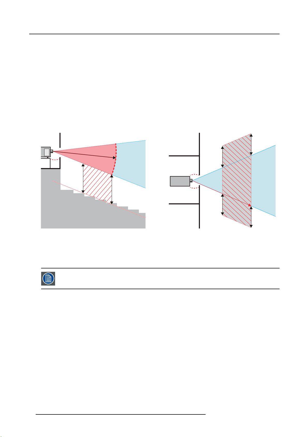
RA TH
SH
Image 1-1
A Side View
BTopView
RA Restricted Area
PR Projector
TH Theater
RZ Restriction Zone in the theater
SH Separation Height
SW Separation Width
Regarding the SH Distance: For Cinema applications, the distance must be >2m. For Concert applications,
thedistancemustbe>3m.
HD
RZ
SH
TH
SW
RZ
SW
RA
PR
HD
SW
1m
SW
(B) TOP VIEW(A) SIDE VIEW
Based on national requirements, no person is allowed to enter the projected beam within the zone between the projection lens and
the related hazard dis tance (HD). This shall b e physically impossible by creating sufficient separation height or by placing bar riers.
The minimum separation height takes into account the surface upon which persons other than operator, performers or employees
are permitted to stand.
On image 1-2 a typical setup is displayed. It must be verified if these minimum requirements are met. If required a restricted zone
(RZ) in the theater must be established. This c an be done by using physical barrier, like a red rope as illustrated in image 1-2.
The restricted a rea sticker can be replaced by a sticker with only the sy mbol.
8
601–0400 F90 SERIES. 10/05/2017
Page 13
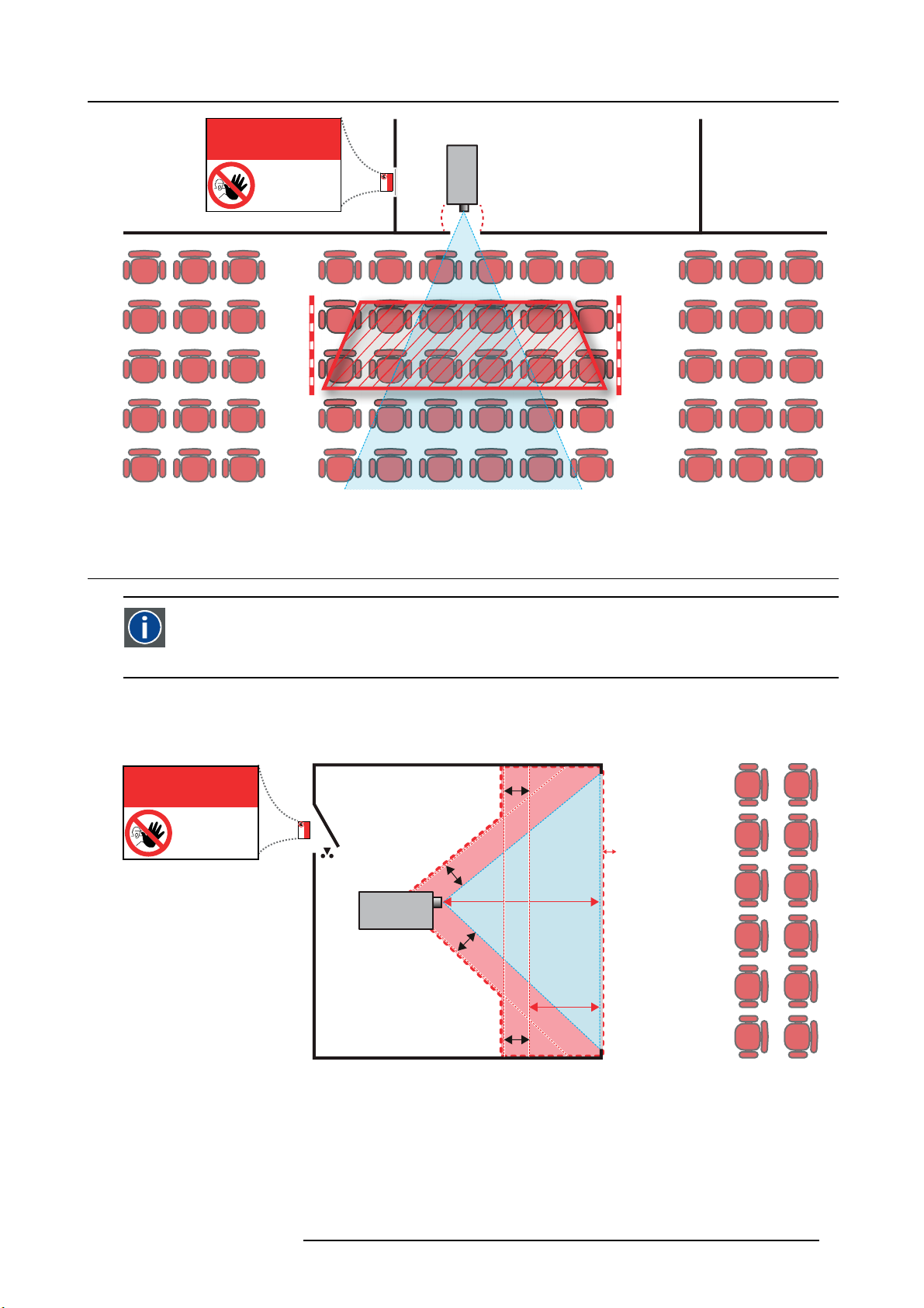
Image 1-2
RESTRICTED
AREA
AREA
1. Safety
PR
RESTRICTED
1.5 Hazard Distance for fully closed projection system
HD
Hazard Distance (HD) is the distance measured from the projection lens at which the intensity or the energy per surface
unit becomes lower than the ap plicable exposure limit on the cornea or on the skin. The light beam is considered (to
be) unsafe for exposure if the distance from a person to t
he light source is less than the HD .
Restriction Zone RZ Based on the HD
The projector is also suitable for rear proje
in image 1-3 two areas should be considered: the restricted enclosed pr ojection a rea (RA) and the observation area (TH).
RESTRICTED
ction applications; projecting a beam onto a defuse coated projection screen. As displayed
RA TH
sw
AREA
RESTRICTED
AREA
HDDIFFUSE
RZ
sw
PR
sw
PD
HD
REFLECTION
Image 1-3
RA Restricted Access location (Enclosed projection area)
PR Projector.
TH Theater (observation area).
RZ Restriction Zone
PD Projection Distan
SW Separation Widt
Restriction zo
h. Must be minimum 1 meter.
ne (RZ) based on the HD continued.
For this type of setup 3 different HD sh all be considered:
601–0400 F90 SERIES. 10/05/2017
sw
9
Page 14
1. Safety
• HD as discussed in "High Brightness precautions: Hazard Distance (HD)", page 6 , relevant for intrabeam exposure.
• HDreflection : the distance that has to be kept restrictive related to the reflected light from the rear projection screen.
• HDdiffuse : the relevant distance to be considered while observing the defuse surface of the rear projec tion sc reen.
As desc ribed in "High Brightness precautions: Hazard Distance ( HD)", page 6 , it is mandatory to create a restricted zone within
the beam areas closer than any NOHD. In the enclosed projection area the combination of two restricted zones are relevant: The
restricted zone of the projected beam toward the screen; taking into account 1 meter Separation Width (SW) from the beam onward.
Combined with the restricted zone related to the rear reflection from the screen (HDreflection); also taking into ac count a 1 m eter
lateral separation.
The HDreflection distance equals 25 % of the difference between the determined HD distance and the projection distance to the rear
projection screen. To determine the HD distance for the used lens a nd projector model see graphs in chapter "HD in f unction of the
lens Throw Ratio (TR)", page 8 .
HDreflection = 25% (HD – PD)
The light emitted from the s creen within the observation shall never exceed the RG 2 exposure limit, determined at 10 cm. The
HDdiffuse can be neglected if the m easured light at the screen surface is below 5000 c d/m² or 15000 LUX.
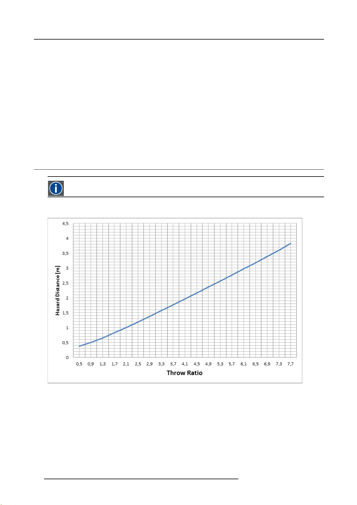
1.6 HD in function of the lens Throw Ratio (TR)
TR (Throw Ra ti o)
The ratio of the distance to the screen (throw) to the screen width.
HD versus Throw Ratio
Image 1-4
Hazard Distance in meters versus Throw ratio of the lens for the F90 projectors
10 601–0400 F90 SERIES. 10/05/2017
Page 15
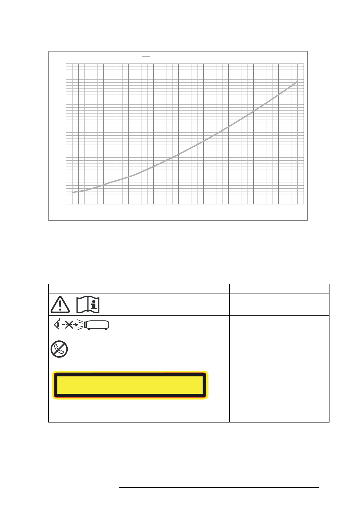
Hazard Distance Thermal Acidental Exposure
䲙
1,8
1,6
1,4
1,2
1
0,8
Hazard Distance [m]
0,6
0,4
0,2
0
0,5 0,9 1,3 1,7 2,0 2,3 2,7 3,1 3,5 3,9 4,3 4,7 5,1 5,5 5,9 6,3 6,7 7,1 7,5
Image 1-5
Hazard Distance in meters versus Throw ratio of the lens for the F70 projectors
Throw Rao
Graphs shows Hazard D istance in m eters versus Throw ratio o f the lens
1. Safety
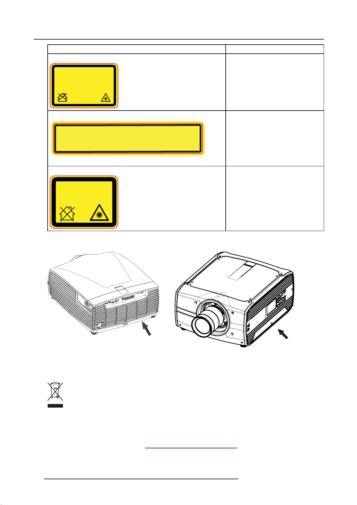
1.7 Safety symbols
Description of safety symbols used in product documentation or on product.
Image Description
Refer to user manual for further information!
Caution! Do not stare into beam, RG2
product.
No telephone! Do not connect to telephone
lines.
For F90 series: Warning Label
For North America, this projector may become RG3 when an interchangeable lens with throw ratio greater than
2.33 is installed. Refer to the manual for the lens list and hazard distance before operation. Such combinations of
projector and lens are intended for professional use only, and are not intended for consumer use.
Ce projecteur peut devenir un projecteur RG3 en cas d'installation d'un objectif interchangeable
dont le rapport de projection est supérieur à 3,15. Veuillez vous reporter au manuel pour en savoir
plus sur la liste des objectifs et la distance de sécurité avant toute utilisation. De telles combinaisons
entre projecteur et objectif sont conçues pour des applications professionnelles uniquement et pas
pour des applications grand public.
This projector may become RG3 when an interchangeable lens with throw ratio greater than 3.15 is
installed. Refer to the manual for the lens list and hazard distance before operation. Such combinations
of projector and lens are intended for professional use only, and are not intended for consumer use.
ᵜᣅᖡᵪᆹ㻵ᣅሴ∄བྷҾ3.15Ⲵᦒ䮌ཤˈᡀѪRG3DŽࡽˈ䈧৲㘳 ѝ䮌ཤঅ઼ড
䐍DŽ
ᵜᣅᖡᵪо䮌ཤ㓴ӵуъ֯⭘ˈ䶎Პ䙊⎸䍩㘵֯⭘DŽ
Caution! For North America: With
interchangeable lens with throw ratio greater
than 2.33, consider hazard distance and
installation requirements for RG3 product.
Refer User Manual.
Caution! With Interchangeable lens
with throw ratio greater then 3.15,
consider hazard distance and installation
requirements for RG3 product. Refer User
manual.
601–0400 F90 SERIES. 10/05/2017 11
Page 16
1. Safety
䲙
Image Description
For F90 series: FDA Label
THIS PRODUCT IS IN CONFORMITY
WITH PERFORMANCE STANDARDS
FOR LASER PRODUCTS UNDER 21
CFR 1040, EXCEPT WITH RESPECT TO
THOSE CHARACTERISTICS
AUTHORIZED BY VARIANCE NUMBER
2016-V-0144 EFFECTIVE
MARCH 6, 2017.
For F70 Series: Warning label
For North America, this projector may become RG3 when an interchangeable lens with throw ratio
greater than 2.5 is installed. Refer to the manual for the lens list and hazard distance before operation.
Such combinations of projector and lens are intended for professional use only, and are not intended
for consumer use.
Ce projecteur peut devenir un projecteur RG3 en cas d'installation d'un objectif interchangeable
dont le rapport de projection est supérieur à 4.7. Veuillez vous reporter au manuel pour en savoir
plus sur la liste des objectifs et la distance de sécurité avant toute utilisation. De telles combinaisons
entre projecteur et objectif sont conçues pour des applications professionnelles uniquement et pas
pour des applications grand public.
For F70 Series: FDA Label
THIS PRODUCT IS IN CONFORMITY WITH
PERFORMANCE STANDARDS FOR LASER
PRODUCTS UNDER 21 CFR 1040, EXCEPT
WITH RESPECT TO THOSE CHARACTERISTICS
AUTHORIZED BY VARIANCE NUMBER
2016-V-0144 EFFECTIVE MARCH 6, 2017.
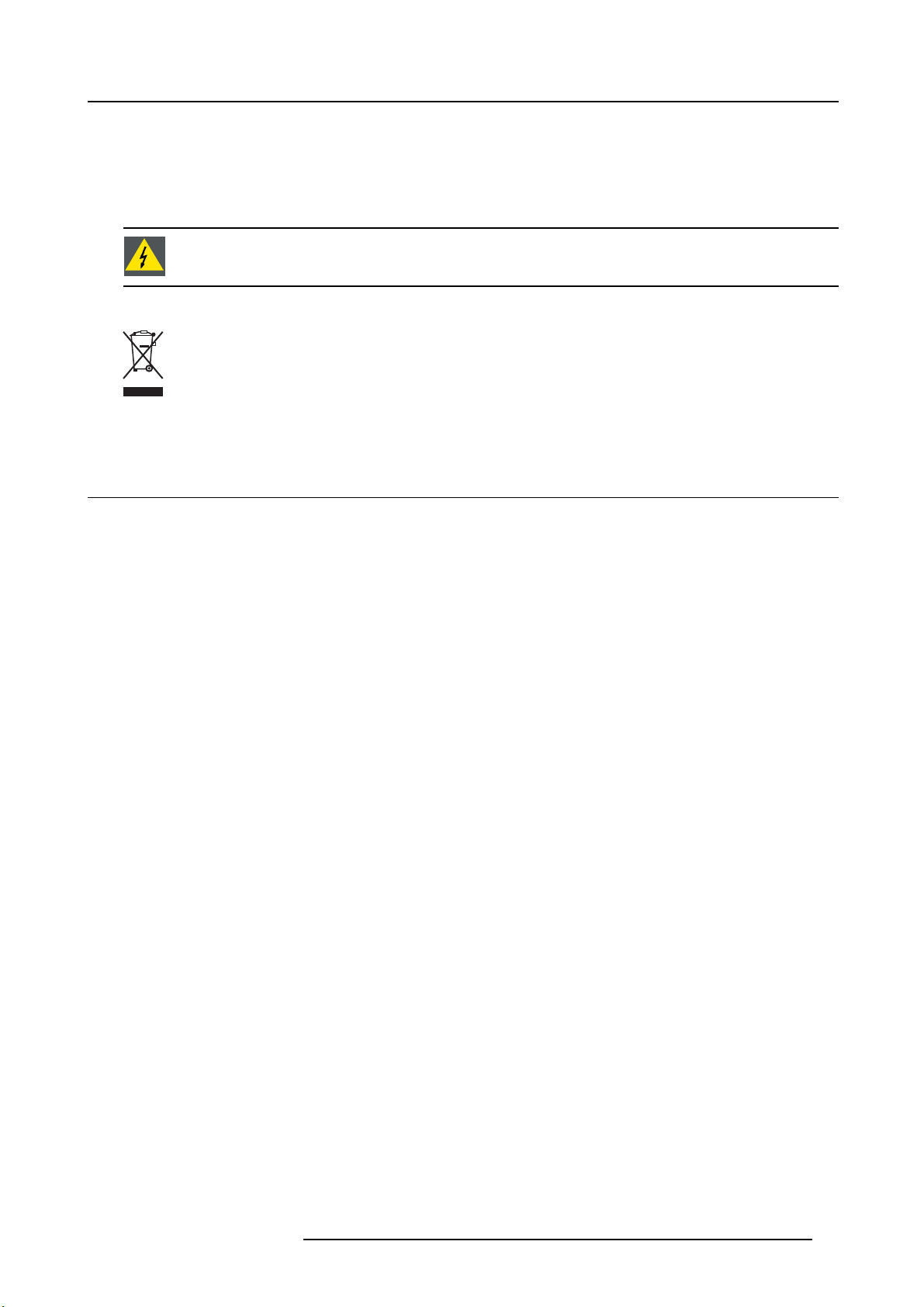
Location of Safety Label
This projector may become RG3 when an interchangeable lens with throw ratio greater than 4.7 is
installed. Refer to the manual for the lens list and hazard distance before operation. Such
combinations of projector and lens are intended for professional use only, and are not intended
for consumer use.
ᵜᣅᖡᵪᆹ㻵ᣅሴ∄བྷҾ4.7 Ⲵᦒ䮌ཤˈᡀѪRG3DŽࡽˈ䈧৲㘳ѝ䮌ཤঅ઼ড
䐍DŽ
ᵜᣅᖡᵪо䮌ཤ㓴ӵуъ֯⭘ˈ䶎Პ䙊⎸䍩㘵֯⭘DŽ
Caution! For North America: With
interchangeable lens with throw ratio greater
than 2.5, consider hazard distance and
installation requirements for RG3 product.
Refer User Manual
Caution! With Interchangeable lens with
throw ratio greater then 4.7, consider hazard
distance and installation requirements for
RG3 product. Refer User manual.
9
Image 1-7
F70 Projector
Image 1-6
F90 Projector
8
Disposal Information
Waste Electrical and Electronic Equipment
This symbol on the product indicates that, under the E uropean Directive 2012/19/EU governing waste from electrical and
electronic equipment, this product must not be disposed of with other municipal waste. Please dispose of your waste equipm ent by
handing it over to a designated collection point for the recycling of waste electrical and electronic equipment. To prevent possible
harm to the environment or human health from uncontrolled waste disposal, please separate these items from other types of waste
and recycle them responsibly to promote the sustainable reuse of material resources.
For more information about recycling of this product, please contact your local city office or your municipal waste disposal service.
For details, pleas e visit the Barco website at: h
12 601–0400 F90 SERIES. 10/05/2017
ttp://www.barco.com/en/AboutBarco/weee
Page 17
WEEE Information
This product conforms to all requirements of the EU Directive on waste electrical and electronic equipment (WEEE). This product
shall be recycled properly. It can be disassembled to facilitate proper recycling of it’s individual parts.
Consult your dealer or relevant public authority regarding drop-off points for collection of WEEE. For details, please visit the Barco
website at: http://www.barco.com/en/ AboutBarco/weee.
WARNING: This product contains chemicals, including lead, known to the S tate of California to cause birth
defects or other reproductive harm. Recycle properly, do not dispose of in ordinary waste!
Turkey RoHS compliance
Türkiye Cumhuriyeti: AEEE Yönetmeliğine Uygundur.
[Republic of Turkey: In conformity w ith the WEEE R egulation]
1.8 RoHS compliance
中国大陆 RoHS (Chinese Mainland RoHS)
根据中国大陆《电器电子产品有害物质限制使用管理办法》(也称为中国大陆RoHS ), 以下部分列出了Barco产品中可能包含的有毒
和/或有害物质的名称和含量。中国大陆RoHS 指令包含在中国信息产业部MCV标准:“电子信息产 品中有毒物质的限量要求”中。
According to the “Management Methods for the Restriction o f the Use of Hazardous Substances in Electrical and Electronic Products” (Also called RoHS of Chinese Mainland), the table below lists the names and contents of toxic and/or hazardous substances
that Barco’s product may c ontain. T he RoHS of Chinese Mainland is in
Industry of China, in the section “Limit Requirements of t oxic substances in Electronic Information Products”.
cluded in the MCV standard of the Ministry of Information
1. Safety
601–0400 F90 SERIES. 10/05/2017
13
Page 18

1. Safety
夃
零件項目(名稱) 有毒有害物質或元素
Component Name Hazardous Substances or Elements
(Pb) (Hg) (Cd) (Cr6+) (PBB) (PBDE)
印製電路配件
Printed Circuit Assemblies
外接電(線)纜
External Cables
緉部線路
Internal wiring
鏡頭支架
Lensholder
激光發生器
Laser
底架
Chassis
外殼
Enclosure
螺帽,螺釘(栓),螺旋(釘),䐭圈緊固件
Nuts, bolts, screws, washers. Fasteners
電源供應商
Power Supply Unit
散熱片(器)
Heatsinks
風扇
Fan
塑膠外殼
Plastic Enclosure
外殼
Enclosure
電池(組)
Batteries
文件茢明書
Paper Manuals
裝置配件
Installation kit
附電池遙控器
Remote control
本表格依據 SJ/T 11364 的規定編制。
This table is prepared in accordance with the provisions of SJ/T 11364.
O: 表示該有毒有害物質在該部件所有均質材料中的含量均在 GB/T 26572 標準規定的限量要求以下。
O: Indicates that this toxic or hazardous substance contained in all of the homogeneous materials for this part is below the
limit requirement in GB/T 26572
X: 表示該有毒有害物質至少在該部件的某一均質材料中的含量超出 GB/T 26572 標準規定的限量要求。
X: Indicates that this toxic or hazardous substance contained in at least one of the homogeneous materials used forth is part
is above the limit requirement in GB/T 26572.
鉛 汞
X O X O O O
X O O O O O
X O O O O O
X O O O O O
X O O O O O
O O O O O O
O O O O O O
X O O O O O
X O O O O O
O O O O O O
X O O O O O
O O O O O O
O O O O O O
O O O O O O
O O O O O O
O O O O O O
X O O O O O
六價壗 多䘳聯䴙 多䘳二䴙慂
Image 1-8
14 601–0400 F90 SERIES. 10/05/2017
Page 19

1. Safety
零件项目 (名称)
Component Nam e
印制电路配件
Printed Circuit Assemblies
外接电( 线)缆
External Cables
內部 线路
Internal wiring
镜头支架
Lensholder
激光发生器
Laser
底架
Chassis
外壳
Enclosure
螺帽,螺钉(栓 ),螺旋( 钉 ),垫圈, 紧固件
Nuts, bolts, screws, washers, Fasteners
电源供应器
Power Supply Unit
散热 片 (器 )
Heatsinks
风扇
Fan
塑胶外壳
Plastic Enclosure
外壳
Enclosure
电池 ( 组)
Batteries
文件说明书
Paper M anuals
装置配件
Installation kit
有毒有害物质或元素
Hazardous Substances or Elements
铅
(Pb)
X
X
XOOOOO
XOOOOO
X
OOO OOO
OOO OOO
X
X
OOO OOO
X
OOO OOO
OOO OOO
OOO OOO
OOO OOO
OOO OOO
汞
(Hg)
O
OOOOO
OOOOO
OOOOO
OOOOO
OOOOO
镉
(Cd)
X
六价 铬
(Cr6+)
OOO
多溴联苯
(PBB)
多溴二苯醚
(PBDE)
附電池遙控器
Remote control
本表格依据SJ/T 11364的规 定编制
This table is prepared in accordance with the provisions of SJ/T 11364.
O: 表示该有毒有害物质在 该部件所有均质材料中的含量均在 G B/T 26572 标准规定的限量要求以下.
O: Indicates that this toxic or hazardous substance contained in all of the homogeneous materials for this part is below the limit
requirement in GB/T 26572.
X: 表示该有毒有害物质至少在该部件的某一均质材料中的含量超出 GB/T 26572 标准 规定的限量要求.
X: Indicates that this toxic or hazardous substance c ontained in at least one of the homogeneous materials used for this part
is above the limit requirement in GB/T 26572.
在中国大陆销售的相应电子信息产品(EIP )都必须遵照中国大陆 《电 子电 气产 品有害物质限制使用标识要求》标准贴 上环保使用期
限(EFUP)标签。Barco产品所采用的EFUP标签(请参阅实例,徽标内部的编号使用于指定产 品)基于中国大陆的《电子信息产品 环
保使用期限通则》 标准。
601–0400 F90 SERIES. 10/05/2017
XOOOOO
15
Page 20

1. Safety
All Electronic Information P roducts (EIP) that are sold within Chines e Mainland must comply with the “Marking for the restriction of
the use of hazardous substances in electrical and electronic product” of Chinese Mainland, marked with the Environmental Friendly
Use Period (EFUP) logo. The number inside the EFUP logo that Barco uses (please r efer to the photo) is based on the “ General
guidelines of environment-friendly use period of electronic information products” of Chinese Mainland.
10
1.9 Contact adresses
For Taiwan:
AWIND Inc., 33F., No. 16. Xinzhan Rd., Banqiao Dist.,, New Taipei City 220, Taiwan
Tel: +886-2-7715-0099, Fax: +886-2-7715-0097
E-mail: sales@awindinc.com
1.10 Product Info
Product info
Image 1-9
product name 產 品名稱:
projector 投影機
model 型號:GP6/GP7
1.11 Statement
EN55032/CISPR32 Class A MME (MultiMedia Equipm
Warning : Th is equipment is compliant with Class A of CISPR 32. In a residential environment this equipment m ay cause radio
interference.
Class A ITE (Information Technology Equipment)
Warning : This is a clas s A product. In a domestic environment this product may cause radio interference in which case the user
may be required to take adequate measures.
ent)
16
601–0400 F90 SERIES. 10/05/2017
Page 21
2. Getting to know the projector
B
R
F
L
T
2. GETTING TO KNOW THE PROJECTOR
Overview
• Main com ponents
• Service and maintenance
• LED status light
• Power on / Standby button backlight indications
• LCD panel
• Local keypad
• Remote c ontrol, Battery installation
• Remote c ontrol, protocol setup
• Functionality overview
• Projector Address
• Connector panel
• Color Wheels
• Optional acces sories
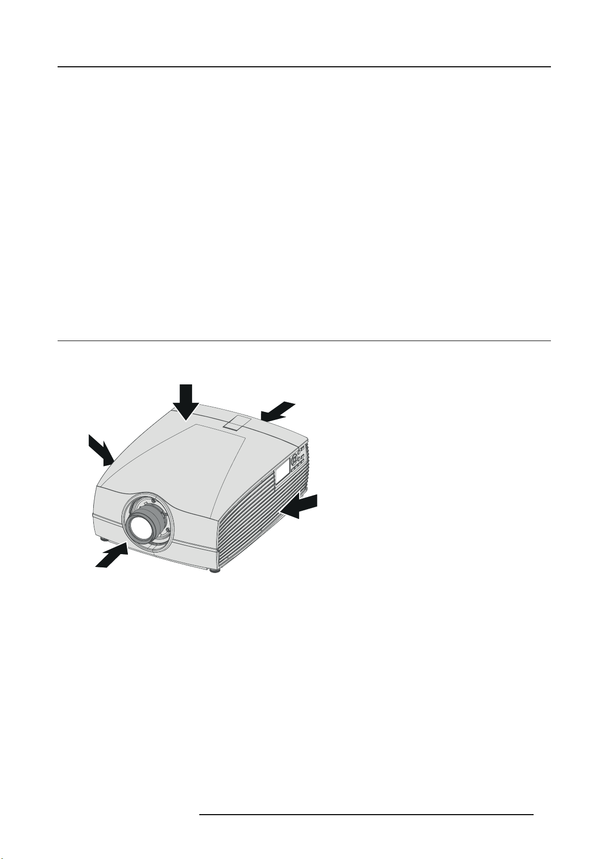
2.1 Main components
Naming conventions
Image 2-1
L Left
TTop
BBack
R Right
F Front
601–0400 F90 SERIES. 10/05/2017 17
Page 22
2. Getting to know the projector
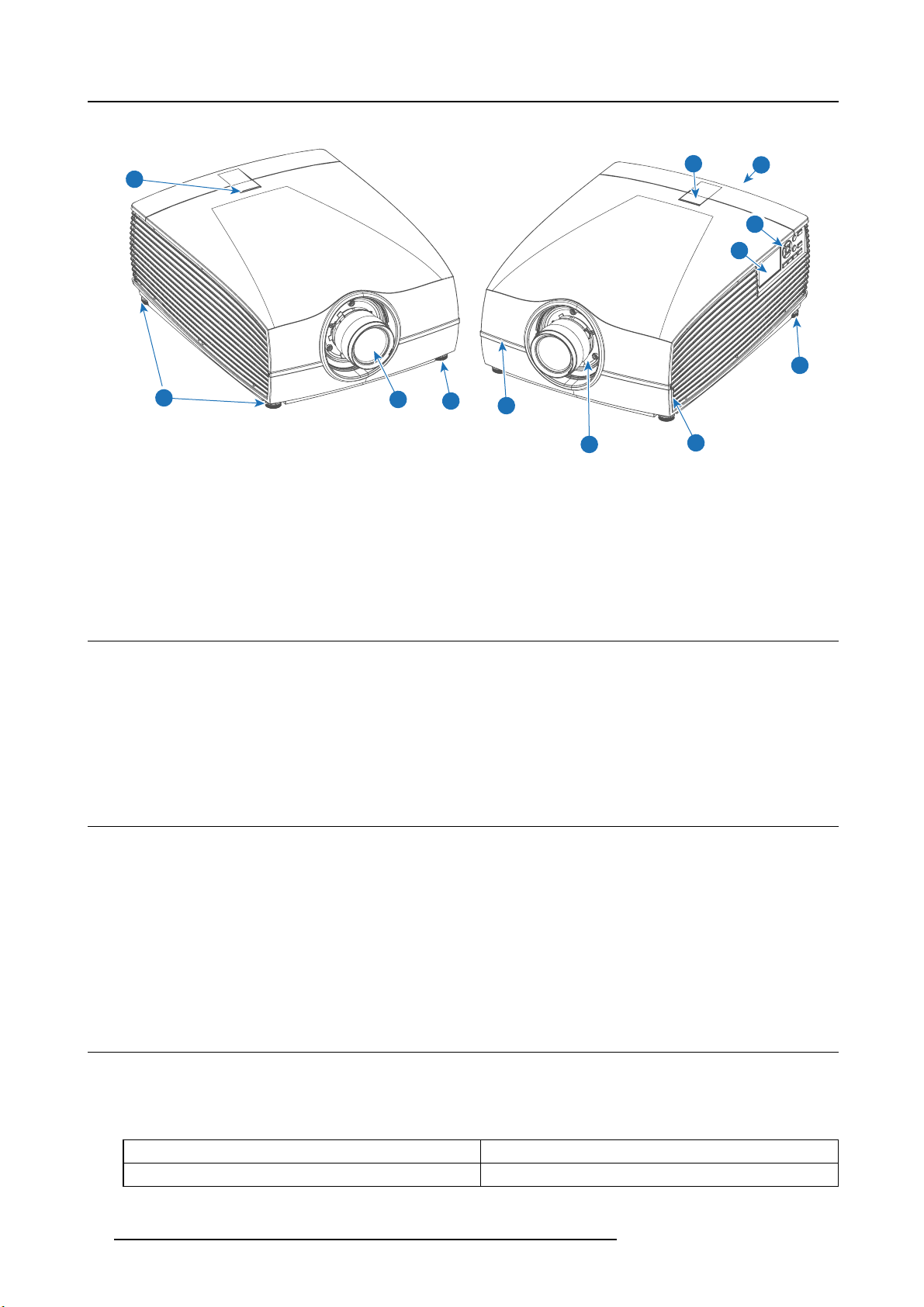
Projector Front
1
2
1
Image 2-2
1 LED status light
2 Adjustable feet
3 Projector lens
4 Lens holder
5 IR Receiver: for remote control communication
6 LCD panel
7 Keypad
8 Connector panel
9 Front USB and triggerboard
5
8
7
6
2
1
3
2
1
5
9
4
1
2.2 Service and maintenance
General
The F90 does not have any user-serviceable parts.
All service tasks must only be carried out by the manufacturer, or a Barco authorized service personnel or Barco technicians.
The projector color wheel is a designed consuma ble that can be replaced by users in the field. See "C hange the color wheel ", page
24 for more information.
2.3 LED status light
About
The F90 status indicator is located on the top side of the projector, near the IR receiver (ref. 1, image 2-2).
During normal operation the LED is unlit. In the event of a c ritical error or high temperature, the LED will display red.
In event of a c ritical error, the projector c annot be restarted until the projector is disc onnected from the power supp ly and then
reconnected again. If the reason for the error persists, the projector will again go to critical error status.
If the root cause of the error is h
the normal operating limitations.
igh temperature, the projector will restart when it has cooled down, and temperatures are back within
2.4 P ower on / Standby button backlight indications
Indicator
In addition to the LE D indicator, the projector also displays status indications in the backlight of the Power / Standby button.
The table below shows the details r egarding this indications.
Operating Status Indication Color / Behavior
On (active) Blue
18 601–0400 F90 SERIES. 10/05/2017
Page 23

2. Getting to know the projector
Operating Status Indication Color / Behavior
Wait on
Standby (off)
Wait
Overheating Red flashing
Configure/upgrade White fast flashing
Standby ECO
Blue flas hing
White
White short flashing
White heartbeat
2.5 LCD panel
About
The LCD panel (reference 1, image 2-3) is located on the right side of the projector, and has two ma
1. Showing the menus and adjustment information. and also a mirror of the OSD, (On Screen Display) described in User Interface
when this is enabled.
2. Information regarding the status of the projector showing this data:
- Projector status
- Network address
- Active source
- Current firmware version
- Operation Data
- Active functions (Enabled Functions).
Toggle between the two indications by using the Menu button on the keypad, or on the remote control
The LCD Display will fade out 30 seconds after the last key operation.
in functions:
2.6 Local keypad
About
The Keypad gives direct access to s everal functions, in addition to access to the menu system. The keypad and remote control
functions are equal.
The keypad has a back light that can be switched o n and off manually. The light turns off automatically after a preset time.
The keys are equipped with white and blue backlit LEDs. Power button is equipped with white, blue and red backlit. The LEDs are
controlled according to the features available.
1
2
3 4
5
6
10
Image 2-3
601–0400 F90 SERIES. 10/05/2017 19
9 8
7
Page 24

2. Getting to know the projector
Item
Name Description
No.
1
LCD Display Shows Projector status and navigation menu.
2 Navigation keys
3
OSD Display Enables the Home Menu on the LCD screen and the OSD.
4
Standby Power on / standby
5Back
6
OSD ON/OFF Deactivate the On Screen Display (OSD). Only critical w arnings will be displayed.
7 Input
8
Shutter Enable and disable the lens shutter function. This is not a mec hanical shutter, but it toggles
9 Test Patterns
10 Lens
Navigation arrows (up, down, left, right), confirm selection (
Undo action / back to previous screen.
Shortcut to input source m enu on LCD. Use navigation keys to select and enable input.
the laser source on and off. Backlight is red when the shutter are enabled.
Shortcut to test pattern menu on LCD. Use navigation keys to select the desired pattern.
Shortcut to lens function. A test pattern displays on the OSD. LCD screen displays the
navigation keys to manage and confirm actions.
)
2.7 Remote control, Battery installation
Where to find the batteries for the remote control ?
The b atteries are not placed in the remote control unit to avoid control operation in its package, resulting in a s horter battery life
time. At delivery the batteries can be found in a separated b
install the batteries first.
ag attached to the remote control unit. Before using your remote control,
How t o install
1. P ush the battery cover tab with the fingernail a little backwards (1) and pull, at the s ame time, the cover upwards (2).
1
Image 2-4
2. Insert the two AA size batteries, making sure the polarities match the + and - m arks inside the battery compartment.
+
-
-
+
2
Image 2-5
3. Insert (1) both lower tabs of the battery cover in the gaps at the bottom of the remote control, and press (2) the cover until it clicks
in place.
20
601–0400 F90 SERIES. 10/05/2017
Page 25

2. Getting to know the projector
2
Image 2-6
+
-
When replacing batteries, t he broadcast address o f the RCU will be reset to its default value ’0’.
1
-
+
CAUTION: Replace with the correct battery type. Use two AA size batteries. There is a risk of explosion if the
battery is replaced with an incorrect type.
CAUTION: Replace the battery as explained above. There is a risk of explosion if the battery is incorrectly
installed.
2.8 Remote control, protocol setup
About the used protocol
The protocol is the code send out by th e remote control when a button is pressed. Depending on this code, the projector can decode
the signals. The remote control can be used with two different protocols, RC5 and NEC. Depending on the projector to control the
remote control can be switched between these protocols.
Which protocol to use
•TheNEC protocol have to be used for Barco projectors based on the Pulse platform: F 70, F80, F90, HDX 4K , UDX, ...
•TheRC5 protocol have to be use all other Barco projectors: HDX W, HDF W, HDQ 2 K, ...
How to set
1. R emov e the cover. For more info on how to remo ve, see "Remote c ontrol, B attery installation", page 20.
2. P lace the switch in the N EC position.
Image 2-7
601–0400 F90 SERIES. 10/05/2017 21
Page 26

2. Getting to know the projector
2.9 Functionality overview
Remote Control Unit buttons
1
2
3
4
5
6
7
8
9
10
11
12
13
14
15
24
23
22
21
20
19
18
17
16
1
Button pressed indicator.
2
Shutter Open.
3
Shutter Close.
Touch Panel O n/Off. (Not in
4
use).
5
OSD On/Off.
6
Lens Zoom.
7
Lens Shift.
8
Menu Activation.
9
Menu Selection, OK button.
10
Menu Navigation.
11
Input Selection.
12
Address button.
Numeric buttons.
13
Backspace (while entering
14
values)
XLR connector.
15
Decimal mark (while entering
16
values)
Macro button. (Not in use)
17
Menu Bac k.
18
Default button. (Not in use).
19
Lens Focus.
20
Real Color menu..
21
Test Patterns.
22
Power On.
23
Power Off.
24
Stereo Jack.
25
RCU On/Off.
26
2625
The projector re mote control is a full feature wireless rem ote control, powered by two (2) standard AA batteries. The battery compartment is on the back side of the remote control.
The remote control is backlit for use in dark environments. It also has an Jack connector for wired connec tion to the projector. When
the wire is connected, the IR beam is s witched off.
2.10 Projector Address
Projector address
Address installed in the projector to be individually controlled.
Broadcast ad dress
Projector will always execute the command coming from a RCU programmed with that broadcast address.
2.10.1 Controlling the projector
Why a projector address?
As more than one projector can be installed in a room, each pr ojector should be separately addressable with an RCU or com puter.
Therefore each projector ha
s its own address.
Set up an individual Project
The set up of a projector address can be done via the software.
22
or Address
601–0400 F90 SERIES. 10/05/2017
Page 27

2. Getting to know the projector
Projector controlling
Every projector requires an individual address between 0 and 255.
When the address is set, the projector can be controlled now:
• with the RCU: only for addresses between 0 and 31.
• with a computer: for any address between 0 and 255.
Broadcast Address
Every projector h as a broadcast (common) address ’0’ or ’1’. The default address is ’0’.
The choice between ’0’ and ’1’ c an be selected in the GUI: “Sy stem Settings” → “Communication” →“IR Control “.
Placing new batteries in the remote control o r p lugging t he remote to a projector via XLR cable will automatically reset the address back to its default value ’0’.
2.10.2 Displaying and Programming addresses into the RCU
Displaying the P roje ctor Address on the Screen.
1. P ress the Address button to s ee the projector address (proximately 2 seconds).
The projector ’s address is displayed on the LCD status screen.
How to Program an Address into the RCU?
1. P ress the Address button until the Button pressed indicator lights up continuously (
2. E nter the address w ith the digit buttons within the time the indicator lights u p (also proximately 5 seconds).
Note: That address can be any value between 0 and 31.
Tip: A few examples:
To enter address 3, press "3" digit button on the RCU to set the RCU’s address to 3 and wait until the button pressed
indicator is out. Alternatively, you c an also press “0” and “3”. This way, he button pressed indicator goes out immed iately.
To enter address 31, then press “3” and “1” on the digit button on the RCU and the button pressed indicator goes out
immediately.
proximately 5 seconds).
2.11 Connector panel
General
The source input panel is located at the back of the projector. For source specifications, see "Connector specifications", page 45.
Image 2-8
Name Pcs Description Purpose
DMX IN 1 DMX 512 input
DMX OUT
RS-232
Sync
Trigger 3 (one in
1 DMX 512 output
1 9–pin DB9 c onnector
3
front, two
on rear
panel)
BNC Sync Port IN/OUT; B idirectional
mini-DIN (1x 3D sync Out, and 2x
Sync In/Out)
12VDC - 0,5A (6W) For Controlling Peripherals, like motorized screens, curtains
For Projector Control
For Projector Control
For Projector Control. A llows for wired remote control and
monitoring of m any projector functions used in installation
environments
For Projector ControlThis is mainly used in multiple projector
installations with requirement of synchronization between
the units
etc. Give 12V output when projector are switched onSee
also the note below.
601–0400 F90 SERIES. 10/05/2017 23
Page 28

2. Getting to know the projector
Name Pcs Description Purpose
RC
USB
LAN 1
DP 2
DL-DVI-D 2
HDMI 1
HDBaseT 1
SDI
1
3
2
Regarding the Trigger Outpu t: If these outputs are loaded too heavy, there is a risk that the p rojector will go
in reset mode, and restart. This causes no dam age to the projector, but is an undesirable resp onse. This
will also happen if the startup current for the external equipment is too h igh, even though the nom inal p ow er
consumption is less than 0,5A.
Jack connector for wired remote For Projector Control
USB 2.0 type A, 4 pin( 2x Rear and
1x Front)
Standard RJ45 connector For Projector Control
Standard display port
Dual DVI-I 1.0 (DVI_D Functionallity).
Standard HDMI 2.0
Standard RJ45 8P8C Connector For Projector Control
SDI1 is Input, SDI 2 is pass through.
(out)
Connectors
For Software upgrade
For Projector Input
For Projector Input. These connectors can also be used to
form one uniform image by feeding half of the image into
each connector. HDCP compliant for sources up 165 Mhz
For Projector Input
For Projector Input
2.12 Color Wheels
Overview
• Color Wheel range
• Change the color wheel
2.12.1 Color Wheel range
About
The F90 is delivered with two (2) different color wheels: COLOR and BRIGHTNESS.
COLOR delivers great depth of color and a broad gamut.
BRIGHTNESS provides an extra bo ost to white segments and very good primary and secondary c olors, which makes it ideal for
brightness critical applications.
The F90 is designed so that users can change the
2.12.2 Change the color wheel
CAUTION: The F90 contains no user serviceable parts except the Color Wheel. Attempts to modify/replace
mechanics or electronics inside t he housing or compartments will v iolate any warranties and may be hazardous.
CAUTION: When placing the projector on the right side for colorwheel replacement, ensure that the projector
are properly secured in this position. Ensure also that the surface used for this operation is suitable with
respect to flatness. It may result in great danger to personnel and equipment if the projector overturning from
the upright position.
color wheel quickly and eas ily w hilst on site, without the use of special tools.
The system is automa tically configured with the correct CW algorithms following the product ID of the CW.
The CW assem bly contains no serviceable parts, and further de-assem bly should not be attempted.
24 601–0400 F90 SERIES. 10/05/2017
Page 29

2. Getting to know the projector
The bo ttom of the packaging container have a cut out that is intended for placing t he projector in a u pright
position, on the right side. This is suitable as docking during ch ange of the colorwheel. Remove the middle
longitude spacer in the con tainer bottom in order to release this cutout.
A video illustration of the complete Colorwheel change process is available in the F90 product site on the web,
under the fi le “Media & Assets”. h
mens-4K-UHD-DLP-laser-phosphor-projector.aspx#!media
This video visualize the process described below.
ttps://www.barco.com/en/Products/Projectors/Venue-projectors/11800-lu-
How to replace the color wheel (CW)
1. P lace the projector on its side (right or left) on a flat surface.
2. Release the seven (7 ) captive screws on the projector bottom. Rem ove the bottom cover carefully.
3. R elease the three (3) captive screws to open CW cover.
4. Release the three (3) captive screws holding the CW in place.
5. Carefully remove the color wheel.
6. Replace with the new color w heel.
7. Reinstall the three (3) ca ptive screws for holding the CW in place.
8. R einstall the three (3) captive screws of the CW cover.
9. Replace the projector bottom cover, and reinstall the seven (7) captive screws.
10.Reposition the projector so that its bottom is sitting flat on a level surface.
2.13 Optional accessories
WARNING: Always use Rigging Frame when the projector are installed outside a flat horizontal surface, o r
being stacked together with several projectors.
Rigging frame
Item num ber Item description
B593624 Rigging frame
Image 2-9
The F90 rigging frame is a rugged, easy to install frame designed to streamline the process of installing one or more projectors.
When installed in the fram e, the projector:
• can be rotated around x , y a nd z axis in order to obtain a seamless adjustment.
• can be installed from a truss or on pedestal
• can be easily stacked one on top of one another, for instance in dual- or multi- channel installations
601–0400 F90 SERIES. 10/05/2017
25
Page 30

2. Getting to know the projector
Flight case
Item num ber Item description
B593624 Flight case
Image 2-10
The F90 flight case is custom-designed to ship the projector, including flight frame, signal a nd power cords an d up to two lenses.
The case is fully-lined to protect the projector and lenses during trans it and storage.
26
601–0400 F90 SERIES. 10/05/2017
Page 31

3. LENSES
About
Overview
• Approved Lenses
• Lens ran ge
• Replace a lens
• Lens s hift
• Adjust z oom, focus and iris
3.1 Approved Lenses
Approved Lenses
Partnumber Description
R9801214
R9801218
R9801228
R9801209
R9801225
R9801249
3. Lenses
Compliance
FLD 1.6 - 2.32 : 1 (EN11)
FLD0.74: 1(EN12)
FLD 1.24 - 1.6 : 1 (EN13)
FLD 2.37 - 3.79 : 1 (EN14) approved – professional use only
FLD1:16: 1(EN15)
FLD 3.8 - 6.5 : 1 (EN16) approved – professional use only
approved
approved
approved
approved
R9801216
R9801226
R9801230
R9801211
R9801220
R9801221
R9801295
PN_EN58
This projector may become Risk Group 3 (RG3) whe n an interchangeable lens with throw ratio greater than 3.15 is installed. For
Northern America, installation requirements according to Risk group 3 (RG3) must be followed when interchangeable lens with throw
ratio greater than 2.33 is installed.
Refer to the manual chapter 1.7 for the throw ratio versus hazard distance before o peration.
FLD+ 1.7 - 2.5 : 1 (EN41)
FLD+ 0.8 : 1 (EN42)
FLD+ 1.2 - 1.7 : 1 (EN43)
FLD+ 2.5 - 4.6 : 1 (EN44) approved – professional use only
FLD+ Long Focus 0.8 - 1.21 : 1 (EN45)
FLD+ Short Focus 0.8 - 1.21 : 1 (EN46)
FLD+ 0.65 : 1 (EN47)
FLD+ 0.28 : 1 (EN58)
approved
approved
approved
approved
approved
approved
approved
3.2 Lens range
CAUTION: Alw ays remove the lens from the lens holder before moving or transporting the projector. Failure
to do this may cause damage to the lens holder and prism.
Available lenses — WUXGA
The FLD lens range is custom-engineered for WUXGA and 1080 projectors.
The electrical connection to the lens motors is via a spring probe contact (pogo) pin array on the bayonet mount.
The p rojector will automatically detect and identify the lens when it is installed. Automatic detection is not available for 3rd party
lenses.
601–0400 F90 SERIES. 10/05/2017
27
Page 32

3. Lenses
EN11 EN12 EN13 EN14 EN15 EN16 EN33
Image 3-1
Name Description Part number Weight
FLD Lens 1.6 - 2.32 : 1
(EN11)
1.6-2.32 : 1 (WUXGA)
R9801214 2.2 kg
FLD Lens 0.74 : 1 (EN12) 0.74:1 (WUX GA)
FLD Lens 1.24 - 1.6 : 1
(EN13)
FLD Lens 2.37 - 3.79 : 1
(EN14)
FLD Lens 1.16:1 (EN15) 1.16 : 1 (WUXGA) R9801225 2.4 kg
FLD Lens 3.80 - 6.50 : 1
(EN16)
Name
FLD Lens 1.6 - 2.32 : 1
(EN11)
FLD Lens 0.74 : 1 (EN12) 2.1 Yes 2.1-6.5
FLD Lens 1.24 - 1.6 : 1
(EN13)
FLD Lens 2.37 - 3.79 : 1
(EN14)
FLD Lens 1.16:1 (EN15)
FLD Lens 3.80 - 6.50 : 1
(EN16)
1.24 - 1.6 : 1 (WUXGA)
2.37 - 3.79 : 1 (WUXGA)
3.8 - 6.5 : 1 (W UX GA) R9801249 2.5 kg
Working F# Iris / Iris F#
2.1-2.52 Yes 2.1-6.5 1.45 33.2-48.1 2.0-15
2.1-2.22 Yes 2.1-6.5 1.3 25.59-33.24 1.0-15
2.1-2.72 Yes 2.1-6.5 1.6 49.1-78.6 3.0-30
2.1 Yes 2.1-6.5
2.1-2.66 Yes 2.1-6.5 1.74 78.3-136.2 4.0-40
Zoom Ratio Focal Length
-
-
R9801218 1.9 kg
R9801228 2.6 kg
R9801209 2.5 kg
Focus Range (m)
(mm)
16.35 0.5-5
23.98 1.5-15
Available lenses — 4K, WUXGA, WQXGA
The FLD+ (EN4X) lens range is custom-engineered for WQXGA projectors.
The electrical connection to the lens motors is via a spring probe contact (pogo) pin array on the bayonet mount. The projector will
automatically detect and identify the lens when it is installed. Auto matic detection is not available for 3rd party lenses.
EN41
Image 3-2
28 601–0400 F90 SERIES. 10/05/2017
EN42 EN43 EN44 EN45 EN46
Page 33

Name Description Part number Weight
FLD+ Lens 1.7 - 2.5 : 1 (EN41) 1.58 - 2.33 : 1 (WUXGA) / 1.7 - 2.5 : 1
FLD+ NV Lens 1.7 - 2.5 : 1
(NV41)
FLD+ Lens 0.8 : 1 (EN42) 0.75 : 1 (WUXGA) / 0.8 : 1 (W QXG A)
FLD+ Lens 1.2 - 1.7 : 1 (EN43) 1.12 - 1.58 : 1 (WUXGA) / 1.2 - 1.7 : 1
FLD+ NV Lens 1.2 - 1.7 : 1
(NV43)
FLD+ Lens 2.5 - 4.6 : 1 (EN44) 2.33 - 4.3 : 1 (WUXGA) / 2.5 - 4.6 : 1
FLD+ Lens 0.75 - 1 .13 : 1 (EN45) 0.75 - 1.13 : 1 (WUXGA) / 0.8 - 1.21 :
FLD+ Lens 0.75 - 1 .13 : 1 (EN46) 0.75 - 1.13 : 1 (WUXGA) / 0.8 - 1.21 :
FLD+ NV Lens 0.8 - 1.21 : 1
(NV46)
FLD+ Lens 0.65 : 1 (EN47) 0.61 : 1 (WUXGA) / 0.65 : 1 (WQXGA) R980129 5 5.4 kg
(WQXGA)
IR Optimized, 1.58 - 2.33 : 1 (WUXGA) /
1.7-2.5: 1(WQXGA)
(WQXGA)
IR Optimized, 1.12 - 1.58 : 1 (WUXGA) /
1.2-1.7: 1(WQXGA)
(WQXGA)
1(WQXGA)
1(WQXGA)
IR Optimized, 0.75 - 1.13 : 1 (WUXGA)
/ 0.8 - 1.21 : 1 (WQXGA)
R9801216 2.54 kg
R9801216 2.54 kg
R9801226 2.7 kg
R9801230 2.84 kg
R9801286 2.84 kg
R9801211 3.08 kg
R9801220 3.04 kg
R9801221 3.14 kg
R9801287 3.14 kg
3. Lenses
Name Working F# Iris / Iris F# Zoom Ratio Focal Length
FLD+ Lens 1.7 -
2.5 : 1 (EN41)
FLD+ NV Lens 1.7
- 2.5 : 1 (NV41)
FLD+ Lens 0.8 : 1
(EN42)
FLD+ Lens 1.2 -
1.7 : 1 (EN43)
FLD+ NV Lens 1.2
- 1.7 : 1 (NV43)
FLD+ Lens 2.5 -
4.6 : 1 (EN44)
FLD+ Lens 0.75 -
1.13 : 1 (EN45)
FLD+ Lens 0.75 -
1.13 : 1 (EN46)
FLD+ NV Lens 0.8
-1.21:1(NV46)
FLD+ Lens 0.65 :
1 (EN47)
2.1-2.5 Yes 2.1-6.5 1.47 33.70-49.54 1.5 - 15
2.1-2.5 Yes 2.1-6.5 1.47 33.70-49.54 1.5 - 15
2.1 Yes 2.1-6.5
2.4-2.7 Yes 2.4-6.5 1.42 23.95-34.02 1.5 - 15
2.4-2.7 Yes 2.4-6.5 1.42 23.95-34.02 1.5 - 15
2.1-2.93 Yes 2.1-6.5 1.85 49.52-91.60 2.5-25
2.4-3.29 Yes 2.4-6.5 1.51 15.85-23.93 5.0 - 30
2.4-3.29 Yes 2.4-6.5 1.51 15.98-23.99 0.7 - 7
2.4-3.29 Yes 2.4-6.5 1.51 15.98-23.99 0.7 - 7
2.1 Yes 2.1-6.0
-
-
3.3 Replace a lens
(mm)
Focus Range (m)
16.12 0.7 - 7
12.6 0.5 - 4.0
Lens lever
The F90 lens mount and lens lever is designed to prevent damage to the lens board while providing an easy and stable lens change
procedure.
The lens lever, located at the bottom of the lens mount (ref. ) slides between two positions, far left (default position — locked) and
far right (unlocked).
Always activate the projector shutter before attempting to remove or install a lens.
To do this, press the shutter button on the keyp ad, or shutter CL on the rem ote, to activate the shutter. Th e
keypad button will illuminate red when the shutter is activated.
Press the shutter button again, or sh utter OP on the rem ote, to d eactivate the shutter and resume normal
operation. The keypad button will illuminate white when the shutter is deactivated.
601–0400 F90 SERIES. 10/05/2017 29
Page 34

3. Lenses
Image 3-3
Install a lens
1. Verify that the projector shutter is deactivated (shutter is
2. Verify that the lens release lever is in its default position at the far left of the slide, as illustrated.
3. Remove the protective cap at the lens bayonet end
4. A lign the lens so that the red marking on the bayonet is facing upwards, towards the red ma rking on the top of the projector
cabinet.
5. P osition the lens bay onet into the projector lens m ount and sup
6. S lide the lens lever to the far right.
7. Verify that the lever is firmly in place at the far right end of the s lide before removing your hand from the lens.
deactivated when the shutter icon on the projector keypad is red).
port in place with one hand.
Image 3-4
Removealens
1. S upport the lens with on e hand.
2. Use the other hand to push the lens release le
3. P ull the lens straight out of the projector lens moun t.
4. Replace with another lens, or install the projector lens cap.
Image 3-5
30 601–0400 F90 SERIES. 10/05/2017
ver in and then slide it to the far left of the slide.
Page 35

3.4 Lens shift
General
Use the Remo te control or the keypad on the P rojector to adjust the lens s hift mechanism.
The lenses can be shifted vertically and horizontally to facilitate precise image positioning in single and multiple projecto r systems.
The projector allows for horizontal and vertical shift in both directions. Always place the projector perpendicular to the screen, and
use the lens shift to align the picture.
If not possible to align the projector perpendicular to the s creen, due to environmemt of other, see chapt
er "Warp", page 56
Indexing
The position (index) iris and shift (horizontal and vertical) can be read out and set. This allows for dynamic control of these functions
from an external control s ystem.
Indexing of zoom and focus a re supported on lens ID EN6x (EN61) range
3.5 Adjust zoom, focus and iris
General
Zoom controls the size of the projected image.
Focus controls the sharpness of the projected image.
Iris controls the contrast and focus depth of the image. Dec reasing the iris stop will increase contrast and image depth, at the same
time as it decreases brightness.
Lens zoom, focus and iris adjustments are motorized. You can use the r emote control, local keypad, OS D and/or RS-232 commands
to adjust the lens zoom , focus and iris positions.
3. Lenses
Not all lenses have zoom or iris control. The matrix b elow shows what controls are available per lens.
Iris will be available for future SW upgrades.
EN11 EN12 EN13 E N 14 EN15 EN16 EN33 EN41 EN42 EN43 EN44 EN45 EN46 EN47
Iris
Zoom
Focus
For best results, lens adjustments should be done in the following order: zoom, focus and then iris (w here applicable).
✔✔✔✔✔✔
✔
✔✔✔✔✔✔✔✔✔✔✔✔✔✔
✖
✔✔
✖
✔
✖
✔✔✔✔✔✔✔
✖
✔
✖
✔✔✔✔
✖
601–0400 F90 SERIES. 10/05/2017
31
Page 36

3. Lenses
32 601–0400 F90 SERIES. 10/05/2017
Page 37

4. Physical installation
4. PHYSICAL INSTALLATION
About
This chapter d escribes the phys ical conditions and procedures required when installing the F90, as well as outlines some of the
considerations you should take into acco unt when designing and setting up the projector ins tallation.
Each projector installation is unique, and as such the information in this chapter is only provided as a guideline. Likewise, any images
or graphical r epresentations shown here are for illustrative purposes only.
If you re quire further information and assistance during the installation process, contact a qualified projection technician or your local
support office for advice.
Overview
• Installation process
• Installation conditions
• Initial inspection
• Positioning the projector
• Mounting the projector, general considerations
• Projector safe attachment points
• Throw distance
• Scheimpflug (Boresight) adjustment
• Scheimpflug adjustment procedure
4.1 Installation process
Recommended installation sequence
Item Procedure Read m ore...
1Confirm that the installation area meets all technical a nd
2 Decide where the projector will be mounted "Positioning the projector", page 36
3 Unpack the projector and confirm that all equipment is
4 Mount the projector "Mounting the projector, general considerations", page 36
5
6 Connect the source "Projector source and control connections", page 45
7
8 Set up the image "Image menu", page 53
environmental requirements.
present and in good working order.
Install the pr ojector lens "Replace a lens", page 29
Power up the pr ojector "Power up the p rojector", page 48
"Installation conditions", page 33
"Initial inspection", page 35
4.2 Installation conditions
Environmental conditions
Barco projectors are m anu factured according to specific design standards, which also include environmental
conditions. Failing to follow the terms and conditions outlined in this chapter can result in loss of product
warranty.
The table below summarizes the physical environment in which the projector may be safely operated or stored.
Environment Ambient operating
0 — 500 M
0 – 500 M
500 – 1500 M
601–0400 F90 SERIES. 10/05/2017 33
temperature
10 to 45 °C 10 to 65% -20 to 60 °C, 10 – 90 %
10 to 40 °C 10 to 80% -20 to 60 °C, 10 – 90 %
10 to 40 °C 10 to 80% -20 to 60 °C, 10 – 90 %
Relative humidity Storage Conditions
Page 38

4. Physical installation
Environment Ambient operating
Relative humidity
Storage Conditions
temperature
1500 – 3000 M
Maximum air flow 900 m3/ hour
10 to 35 °C 10 to 80 % -20 to 60 °C, 10 – 90 %
-
NA
AutoDim function
The F90 AutoDim function is integrated in the projector fi rmware. The projector continually senses and calculates the ambient
temperature in the installation location and will, when necessary, automatically dim the light output if the projector is operating in the
extreme ends of the recommended ambient environmental conditions, as illustrated in the graph below.
100
95
90
85
80
Rel. Humidity=45%
Rel. Humidity=55%
Rel. Humidity=65%
Rel. Humidity=80%
Light Output [%]
75
70
34 35 36 37 38 39 40 41 42 43 44 45
Ambient Temperature [oC]
Image 4-1
Mains power requirements
Projector Power requirements
F90 110 — 240 V, 50 — 60 Hz
To protect operating personnel, the Nati
and cabinet be grounded.
In no event shall this projector be operated without an adequate cabinet ground connection.
The AC supply must be installed by a qualified electrician in conformance to local codes. Hardware, wire sizes and conduit types
must comply with local codes.
AutoDim function will be activated when mains power are 110V or below.
onal Electrical Manufacturers A ssociation (NEMA) recommends that the instrument panel
34
601–0400 F90 SERIES. 10/05/2017
Page 39

Ventilation
500 mm
4. Physical installation
1000 mm
Image 4-2
Projector weight and footprint
Weight: 44.5 kg
296 mm
577 mm
Image 4-3
737 mm
4.3 Initial inspection
General
Each projector is inspected and rigorously tested at our production facility to ensure that it is free from any mechan ical or electrical
defects.
Upon receipt of the projector, we recommend that customers inspect the projector for any signs of damage that may have occurred
in transit. If damage is found, file a claim with the shipping carrier im mediately. Notify the Barco Sales and Se rvice office, or your
preferred Barco agent, o
f the damage as soon as possible.
Box Contents
Your projector box should contain the following:
• Projector unit
• Power cord (suitable for region)
• Quick start guide
• Safety manual
• Remote Control
• Additional Color Wheel
601–0400 F90 SERIES. 10/05/2017
35
Page 40

4. Physical installation
The projector lens is delivered in a separate box.
4.4 Positioning the projector
CAUTION: The position and physical securing of the projector must be sufficient to prevent it from accidental
or involuntary movement. Proper securing of the projector is the responsibility of the installer and user. The
Projector are heavy, and can cause severe damage and injuries if falling.
General guidelines
Proper positioning of the projector lessens the overall picture setup time, and ens ures a better image with fewer artifacts.
Focus and sharpness of the image can be adversely affected if the lens axis is not fully perpendicular to the
projection surface.
Using extended cable lengths may result in reduced image quality as well as loss of control information such
as EDID (Extended Display Inform ation Data).
The following guidelines can help you determine the best physical location for the projector.
• Only install the projector on a s turdy flat s urface, or in an approved rigg
• Do not install the projector in a thoroughfare or other area where it is at risk of being pus hed or jostled.
• Allow sufficient free space around the projector for ventilation and exhaust, as described in section "Installation conditions",
page 33.
• Use the throw ratio of the ins talled lens as a guideline for the projector ’s physical distance from the screen.
• Wherever possible, the projector lens surface should be positioned so that it is perfectly perpendicular to the cen ter of the
screen.
Use the projector offset (lens shift), rather than physical angling, to correct any off-center positioning.
• Minimize the source cable length as much as possible.
In general HDBaseT and 3G-SDI are long-haul interfaces and suitable for bespoke installations using relatively long cables.
DP, HDMI and DVI are short-haul interfaces using pre-assembled cables with limited cable lengths.
• Limit the use of power cable extensions wherever possible. Where physical limitations necessitate their use, make sure that
the extension cord has adequate surge protection and meets all electrical requirements of the connection.
• Keep the projector away from equipment that emits electromagnetic energy for example, motors, transformers and elevators.
ing frame.
4.5 Mounting the projector, general considerations
Mounting safety
When mounting a projector in a rig, always use an interface plate (between the projector and the mount) that has provision for a
safety wire or another safety mechanism, to ensure that the projector does not fall down should the interface plate come loose from
the m ount.
Always screw the interface plate securely to the projector body while the projector is on the ground (i.e. cannot fall down). Then
attach proper safety wire between the interface plate and the rig before mounting the projector in the rig
Using 3rd party mounting equipment
The projector has features for mounting into vari
Four m ounting inserts are located on the bottom of projector. The ceiling mount inserts have a pull-strength of more than 4x the
weight of the projector.
The feets can also be removed and threads can be used for additional mounting points. See table below for dimensions.
36
ous system environm ents using 3rd pa rty mounts.
601–0400 F90 SERIES. 10/05/2017
Page 41

Parameter Value
Thread size M12
Length 18mm max 18mm max
Where possible, the projector lens must be positioned exactly p erpen dicular to the center of the sc reen. Use
the projector offset (lens shift), rather than physical angling, to correct an y off-center positioning.
CAUTION: The position and physical securing of the projector must be sufficient to prevent it from accidental
or involuntary movement. Proper securing of the projector is the responsibility of the installer an d user.
CAUTION: Always use a Rigging Frame when the projector shall be mounted in other ways than on the feet,
on a flat surface.
Installation and use of the Rigging Frame are described in document R5906768 F90 Multifunctional Frame —
Installation Manual.
4. Physical installation
The threaded hole in the lower back end of the projector is NOT suitable for lifting or other heavy op erations.
Only for adjustment purposes.
Mounting on a flat surface
1. P osition the projector at the desired location.
2. P ower up the projector.
3. G o to Main Menu / Test Patterns and select an internal hatch pattern to display on the screen.
4. A djust the projector legs until the projected hatch pattern is a level and perfect rectangle.
Adjustable feet
Twisting the adjustable feet in either direction, left or right, allows you to fine-adjust the projector position for precise vertical mechanical alignment.
Raise
Lower
Image 4-4
Mounting to a ceiling
1. Install the projector in to an approved ri
2. Install the rigging frame to the desired location.
3. P ower up the projector.
4. G o to Main Menu / Installation / Orientation and select the correct o rientation for your setup.
See "Orientation", page 55 for more information.
5. G o to Main Menu / Test Patterns and select an i
601–0400 F90 SERIES. 10/05/2017
gging frame.
nternal hatch pattern to display on the screen.
37
Page 42

4. Physical installation
6. A djust the position (height and angle) of the rigging frame until the projected hatch pattern is a level and perfect rectangle.
If applied in a motion rig, care must be taken to stay within the environm ental specifications for vibration and
shock. It may also be necessary to use additional, custom means to stabilize the projection lens to m ake sure
that the projected image remains in position an d properly focused.
4.6 Projector safe attachment points
About
The projector has four anchoring points (ref 1, image 4-5) that can be used w ith the rigging frame and projector installation. There are
an additional 9 fastening points (ref 2 and 3, image 4-5) that can used for attaching light weight accessories and other miscellaneous
equipment. See table below for m ore information.
1
3
Image 4-5
Item Thread dimension Max hole depth Application
1 M6 10mm Anc horpoint /Ceiling / Rig moun t
2 M4 6mm Miscellaneous
3 M6 6mm Miscellaneous
2
4.7 Throw distance
Calculate the installation throw distance
Throw is the distance (D) measured from your projector lens to the screen. To calculate the throw distance for an installation, you
will need two pieces of da
width (W) is 2.4 m eters and the projector lens has a throw ratio ( L) of 0.99:1, then the throw distance (D) will be 2.38 meters.
Calculation: 2.4 x 0.99 = 2.38
The following graphs illustrate the image size (W) and projection distance (D) for each of the projector lenses.
38
ta: the selected lens throw ratio (L) and the h orizontal width (W) of the screen. For example, if the screen
601–0400 F90 SERIES. 10/05/2017
Page 43

Tolerances are typically +/- 5% due to optical (lens) variation.
Throw distance, FLD WUXGA
7.50
4. Physical installation
Image width
m
12.00
Screen diagonal
14.00
7.00
6.50
6.00
5.50
5.00
4.50
4.00
3.50
3.00
2.50
2.00
1.50
1.00
0.50
0.00
FLD Lens 0.74:1 (EN12) (0.5 - 5m)
FLD Lens 1.16:1 (EN15) (1.5 - 15m)
FLD Lens 1.24 - 1.6 : 1 (EN13) (1.0 - 15m)
FLD Lens 1.6 - 2.32 : 1 (EN11) (2.0 - 15m)
FLD Lens 2.37 - 3.79 : 1 (EN14) (3.0 - 30m)
FLD Lens 3.80 - 6.50 : 1 (EN16) (4.0 - 40 m)
11.00
10.00
9.00
8.00
7.00
6.00
5.00
4.00
3.00
2.00
1.00
0.00
13.00
12.00
11.00
10.00
9.00
8.00
6.00
5.00
4.00
3.00
2.00
1.00
0.00
Image 4-6
Projection distance
601–0400 F90 SERIES. 10/05/2017 39
Page 44

4. Physical installation
Throw distance, FLD+ WQXGA / 4K UHD
Image height
7.50
Image width
m
12.00
Screen diagonal
14.00
7.00
6.50
6.00
5.50
5.00
4.50
4.00
3.50
3.00
2.50
2.00
FLD+ Lens 0.65 : 1 (EN47) (0.5 - 4m)
1.50
1.00
0.50
0.00
FLD+ Lens 0.8 : 1 (EN42) (0.7 - 7m)
FLD+ Lens 0.8 - 1.21 : 1 (EN46) (0.7 - 7m)
FLD+ Lens 0.8 - 1.21 : 1 (EN45) (5 - 30m)
FLD+ Lens 1.2 - 1.7 : 1 (EN43) (1.5 - 15m)
FLD+ Lens 1.7 - 2.5 : 1 (EN41) (1.5 - 15m)
FLD+ Lens 2.5 - 4.6 : 1 (EN44) (2.5 - 25 m)
11.00
10.00
9.00
8.00
7.00
6.00
5.00
4.00
3.00
2.00
1.00
0.00
13.00
12.00
11.00
10.00
9.00
8.00
6.00
5.00
4.00
3.00
2.00
1.00
0.00
Image 4-7
Projection distance
40 601–0400 F90 SERIES. 10/05/2017
Page 45

Throw distance, FLD+ WUXGA
7.50
4. Physical installation
Image width
m
12.00
Screen diagonal
14.00
7.00
6.50
6.00
5.50
5.00
4.50
4.00
3.50
3.00
2.50
2.00
1.50
1.00
0.50
0.00
FLD+ Lens 0.65 : 1 (WUXGA) (EN47) (0.5 - 4m)
FLD+ Lens 0.75 - 1.13 : 1 (WUXGA) (EN46) (0.7 - 7m)
FLD+ Lens 0.75 : 1 (WUXGA) (EN42) (0.7 - 7m)
FLD+ Lens 0.75 - 1.13 : 1 (WUXGA) (EN45) (5 - 30m)
FLD+ Lens 1.12 - 1.58 : 1 (WUXGA) (EN43) (1.5 - 15m)
FLD+ Lens 1.58 - 2.33 : 1 (WUXGA) (EN41) (1.5 - 15m)
FLD+ Lens 2.33 - 4.3 : 1 (WUXGA) (EN44) (2.5 - 25 m)
11.00
10.00
9.00
8.00
7.00
6.00
5.00
4.00
3.00
2.00
1.00
0.00
13.00
12.00
11.00
10.00
9.00
8.00
6.00
5.00
4.00
3.00
2.00
1.00
0.00
Image 4-8
Projection distance
4.8 Scheimpflug (Boresight) adjustment
What is Scheimpflug?
The lens holder has to be adjusted s o that the “sharp focus plane” of the projected image falls together with the plane of the screen
(Fp1→Fp2). This is achieved by cha
plane comes to the DMD plane the further the sharp focus plane will be. It can occur that you won’t be able to get a complete f ocused
image on the screen due to a tilt (or swing) of the lens plane with respect to the DMD plane. This is also know n as Scheimpflug’s
law. To solve this the lens plan
remove the tilt (or swing) between lens plane and DMD plane (Lp3→Lp4).
Lp1
Lp2
DMD
Image 4-9
Scheimpflug principle
nging the distance between the DMD plane and the lens plane (Lp1→Lp2). The closer the lens
e must be placed par allel with the DMD plane. This can be achieved by turning the lens holder to
Fp1
SCREEN
Fp2
DMD
Lp3
Lp4
(Scheimpflug)
Fp4
Fp3
SCREEN
601–0400 F90 SERIES. 10/05/2017 41
Page 46

4. Physical installation
Scheimpflug principle
The "plane of sharp focus" can be changed so that any plane can be brought into sharp focus. W hen the DMD plane
and lens plane are parallel, the plane of sharp focus will also be parallel to these two planes. If, however, the lens
plane is tilted with r espect to the DMD plane, the plane of sharp focus will also be tilted according to geometrical and
optical properties. The DMD plane, the principal lens plane and the sharp focus plane will intersect in a line be low the
projector for downward lens tilt.
Scheimpflug adjustment points
Scheimpflug adjustment points are located on the lens mount. The F90 has three (3) set screws and three (3) adjustment screws.
When to apply Scheimpflug?
Scheimpflug correction procedures may only be carried out by suitably trained and experienced tech nicians.
A Scheimpflug correction should only be applied when the overall focus of the projected image is not equally sharp (for example, if the
projector is NOT in parallel with the screen or as a result of a previously misaligned Sc heimpfl ug). Be aware that the consequence of
applying Scheimpflug correction upon a screen not in parallel with the projector is that the projected image differs from the rectangle
shaped image. In other words “distortion” of the projected image occurs. Masking will be required to solve the distortion.
The disadvantage of Masking is loss of content. T herefore it is st rongly recommended to place the projector in parallel with the
projection screen and use the SHIFT functionality of the Lens Holder to match the projected im age with the projection screen. If the
SHIFT range is not sufficient then the projector can be tilted and Scheimpflug can be applied.
4.9 Scheimpflug adjustment procedure
CAUTION: A Scheimpflug adjustment should only be carried out by properly qualified and experienced pro-
jection specialists. A poor Scheimpfl ug adjustment may result in an extremely degraded image and will require
factory—servicing to the projector.
Necessary tools
• Allen key, hex size 4
• Allen key, hex size 6
Preparation
1. P repare the test area. Barco recommends a projector-screen d istance of 2 metres be used for all Scheimpflug adjustments.
Verify that the throw ratio of the installed lens matches the requirem ents of the installation ar ea (projection distance and screen
size).
2. Check that the lens is correctly installed, and lens shift is in centre position.
3. If the installed lens has Iris control, open the Iris a
4. O pen the focus ring all the way up.
5. G o to Main Menu / Test Patterns / Full Screen and select to display the Focus test pattern.
6. Z oom the lens to its widest opening (maximum image size on the screen).
Apply a Scheimpflug correction
1. L oosen the three set screws (reference 1b, 2b, 3b). Use a size 6 hex key to do this.
ll the way up.
42 601–0400 F90 SERIES. 10/05/2017
Page 47

3b
4. Physical installation
1b
Image 4-10
2. A djust the left side Scheimpflug adjustment screw (reference
2b
1) until the test image in the top right side of the screen is in focus.
Useasize4hexkeytodothis.
Note: This process may ca use the other areas of the image to slide out of focus . This is totally normal.
F
1
Image 4-11
3. A djust the right side Scheimpflug adjustment screw (reference 2) until the test image in the top left side of the screen is in focus.
Useasize4hexkeytodothis.
Note: This process may ca use the other areas of the image to slide out of focus . This is totally normal.
F
2
Image 4-12
4. A djust the top Scheimpflug adjustment screw (reference 3) until the test image in the bottom half of the screen is in focus. Use
asize4hexkeytodothis.
Note: This process may ca use the other areas of the image to slide out of focus . This is totally normal.
3
F
Image 4-13
5. Continue adjusting the screws one at a time until the test image is uniformly sharp across all areas of the display.
6. Test the focus by zoomin
g out (minimum image size on screen) and then zooming in again. Verify the image is still sharp. If there
are any deviations to sharpness, repeat steps 2 to 6 until the image is correct.
7. Tighten the three set screws in the following order: left (1b), right (2b) and then top (3b). Use a size 6 hex ke y to do this.
601–0400 F90 SERIES. 10/05/2017
43
Page 48

4. Physical installation
44 601–0400 F90 SERIES. 10/05/2017
Page 49

5. GETTING STARTED
About this chapter
This chapter describes how to set up and optimize your projector setup when the physical installation process is complete.
Overview
• Projector source and control connections
• Power up the projector
• Power down the projector
• Power m odes
• Customize projector settings
• User interface
5.1 Projector source and control connections
Overview
• Making connections
• Connector spec ificat ion s
• Control interfaces
5. Getting started
5.1.1 Making connections
The source switching time varies from 0.5 to 5 seconds.
Source signal connectivity
The connector panel at the back of the pr ojector is used for all source connections.
Source signal connectivity on the projector is:
• 2x Dual Link DVI-I (DVI-D functionality)
• 2x DisplayPort 1.2
• 1x HDM I 2.0
• 1x HDBas eT w/Ethernet
•1x3GSDI
5.1.2 Connector specifications
Overview
•DVI-I
• Display Port 1.2
• HDMI 2.0
•3G-SDI
• HDBase T
5.1.2.1 DVI-I
Specifications
Parameter Value
Connector DVI-I female digital RGB
Signal characteristics DVI 1.0, Digital, TMDS
Max. cable length 25 m (24 AWG)
601–0400 F90 SERIES. 10/05/2017 45
Page 50

5. Getting started
Parameter Value
Max. pixel rate
Scan format
Max. input data resolution
Bit depth 8 bit
EDID
HDCP Supported
330 MHz (dual link), 165 Mhz (single link)
Progressive
1920x1200 60Hz (Single link), 2560x1600 60Hz (Dual
Link).1920x2400 @60Hz
Supported
5.1.2.2 Display Port 1.2
Specifications
Parameter Value
Connector Standard Display port
Signal characteristics
Functionality Mandatory
Max. cable length
Supported Link Rate RBR, HBR1, HBR2
Scan format Progressive
Max. input data resolution 1920x1200 @120Hz (W QXG A ) 3840x2400 @ 60Hz (4K )
Bit depth 8, 10, 12 bit
EDID Supported
HDCP Supported
DP 1.2
15m(24AWG)-RBR;
2m(24AWG)–HBR1,HBR2
5.1.2.3 HDMI 2.0
Specifications
Regarding HDMI 2.0: The decryption protocol HDCP 2.2 are enabled and valid in this unit.
Parameter Value
Connector Standard HDMI
Signal characteristics Digital, TMDS
Max. cable length 15 m (24 AWG)
Max. pixel rate 594MHz
Max. input data resolution 3840x2160 @60Hz
Bit depth 8, 10, 12 bits
EDID Supported
HDCP Supported
Ethernet No
Audio return No
46 601–0400 F90 SERIES. 10/05/2017
Page 51

5.1.2.4 3G-SDI
Specifications
Parameter Value
Standard SMPTE 424M-2006 10bit level A
Connectors 1x) BNC 75 o hm type IEC 60169-8, Amendment 2 1997, A
Bandwidth >3 GHz
Return loss >10dB at 3GHz
Impedance 75 ohm resistive
5.1.2.5 HDBase T
Specifications
Parameter Value
Reference specification HDBaseT 1.0 Specification, June 2010
Connector Standard RJ-45, 8P8C
Signal characteristics
Max. cable length (1080p/48b/60Hz) 100 m (Cat5e/6), Pixel Clock <=225HHz , Video Datarate
Max TMDS Clock Frequency
Max video resolution supported
HDCP Pass-Through Yes, from Source to Projector
IR Extension
RS-232 Extension Not Supported
10/100Mbps Ethernet Pass-Through Not Supported
Fallback to 100B aseT x, IEEE 802.3u
USB Ove r Centre Tap Not Supported
Power Over Ethernet Not Su pported
Audio
LEDs - HD Base Status Operation: Green, Left
HDBaseT
<=5.3Gbps
70 m (Cat5e/6), Pixel Clock >225HHz, Video Datarate
>5.3Gbps
100 m (Cat6a/7), Pixel Clock >225HHz, Video Datarate
>5.3Gbps
270 MH z
1920x1200 @60Hz (WUXGA 60Hz)
Not Supported
Not Supported
Not Supported
Link/Mode: Yellow, Right
5. Getting started
5.1.3 Control interfaces
About
The following control interfaces are available on the projector:
• 1x RS -232 (for projector c ontrol)
• 1x LAN/Ethernet (for projector control
• 3x USB-A ports
Overview
• RS-232
• LAN/Ethernet
• USB-A port
601–0400 F90 SERIES. 10/05/2017
47
Page 52

5. Getting started
5.1.3.1 RS-232
Specifications
Parameter Value
RS-232 connector 1 female DB9 connector (RS232-in) for projector control and
debug
5.1.3.2 LAN/Ethernet
Specifications
Parameter Value
Ethernet connector
Protocols
Speed 10/100 Mbit/1000Mbit
1 RJ45 Connector for projector control (not content)
DHCP, TCP/IP, UDP/P
5.1.3.3 USB-A port
Specifications
Parameter Value
USB connector
Function
Power
Standard USB 2.0
Type A
Firmware upgrade using USB sticks
Power 5V, max 1,5A (out)
5.2 Power up the projector
CAUTION: Sources should always be connected before the projector is powered up
CAUTION: Use only power cords following the unit, designed for your projector model. Do not use unautho-
rized replacements. Do not use power cords which are damaged.
Power up the projector using the keypad or remote
1. Connect the line cord to the projector.
2. P lug the 3–pronged cor d into a ground ed AC outlet.
The projector will b egin warming up, and the backlight of the Standby /power button are flashing white.
3. W he n the backlight on the standby button are constant white, the projector are in standby mode, ready to be switched on.
4. P ress the standby button on the keypad or the
The power button backlight on the keypad will flash blue w hile the projector is warming up.
5. W he n the power button bac klight is steady blue, the projector is ready for use.
power button on the remote to bring the projector up to standby mode.
5.3 Power down the projector
Power down using the keypad or remote
1. D epress and hold the pow er button on the keypad or remote for four (4) seconds.
The Pr ojector is now in cooling down phase.
2. W he n the projector pane l is no longer illuminated, remove the mains power cord from the projector.
48
601–0400 F90 SERIES. 10/05/2017
Page 53

5.4 Power modes
General
The table below details the F90 power modes.
Mode Description
Normal Projector is booted up and t he light source is on
Ready
ECO Standby Light source is switched o ff and projector electronics are
Projector is booted up but the light source is off
powered down
5.5 Customize projector settings
About
The projector display, behavior and user interface can be adjusted to meet individual requirements.
Options include:Home/System Settings/Themes
• Adjust the OSD menu color
5. Getting started
5.6 User interface
Overview
• On S creen Display (OSD)
5.6.1 On Screen Display (OSD)
About
The pro jector on screen display (OSD) is the primary user interface (UI). From here, you can review and adjust all projector and
display settings.
The OSD interface uses tabs to display the main men u. Topics are t hen further sorted and displayed by function: main (topic) —
sub (function) — sub (function).
There are six main menu tabs: Source, Image, Installa
The OSD can be d isabled by pressing the OSD on/off button.
In order to show the OSD, the OSD O n/Off button must be disabled. (White backlight on the button). When
the button have blue illumination, the OSD will not appear, and the display information are only visible on the
LCD Display. Only Critical warn ings will be displayed.
User access levels
The projector’s software platform uses access levels to defi ne what each user can do.
There are two user access levels: S tandard User and Power User. In addition, there is a Service user access for certified Service
personnel.
A standard user has access to all projector functionality and OSD menu items. A power user has, in addition to access to all p rojector
functionality and OSD menu ite ms, access to a number of advanced functions. Access to power user features is password-protected.
Contact your projector supplier for more information.
tion, System settings, Test pattern and Status.
Navigation
You can navigate the OSD using the local keypad or the remote c ontrol.
Press the MENU button to d isplay the OSD.
Use the arrow key s to navigate left, right, up and down.
Press the OK b utton to select a menu topic and get more options.
Use the numeral keys to enter values, or use the arrow keys to move the barscale up or down.
Press ME NU again to exit the menu system.
601–0400 F90 SERIES. 10/05/2017
49
Page 54

5. Getting started
Press the O SD button to deactivate the OSD on the screen. Only critical warnings will be displayed.
Some menu options are reserved for Po wer or Service Users; these will be grayed out and not available for
selection w h en in standard user mode. To access these fe atures, enter your Power or Service Code in the
Service Menu or contact your support representative for more information.
Define values
Menu settings ar e displayed using checkboxes, barscale sliders, and drop-down lists.
To set a value :
• Press OK to select or deselect a c heckbox (turn a function O N or OFF).
• Use the arrow keys to move the barscale slider up or d own on the value line. For a barscale 0-9, each s tep will equal 10% of
the total value.
• To enter the value as a direct number, press ENTER, input th e digit(s), and then Press ENTER again to execute a
mode e.g. ENTER 79 ENTER.
Changes to values are implemented dynam ically.
Menu memory
The OSD menu remembers the last selected sub–item as long as the projector is running. The menu memory is reset when restarting
the projector from standby.
nd exit cursor
50
601–0400 F90 SERIES. 10/05/2017
Page 55

6. Source menu
6. SOURCE MENU
About the Source menu
This menu is used to select, review and con figur e sources into the projec tor. Enables either via the source menu, or the shortcut key.
By navigate through the Home/Source m enu, it will be visible also on the OSD.
By using the shortcut key, the menu occurs only on the LCD display.
Overview
• Connector selection
• Connector Settings
• Using Dual DVI or Dual Display Port
6.1 Connector selection
About
Source / {Source}
Click on the relevant input connector icon to swap or activate the source.
The icon for the active source is highlighted.
The list of displayed sources can be adjusted to include other connectors.
The default selection of connectors displayed is:
•DVI1
•DVI2
• Dual DVI
• Display Port 1
• Display Port 2
• Dual D isplay Port
• HDBaseT
• HDMI
•SDI
6.2 Connector Settings
About
Home/Source/ConnectorSettings
The Connector settings menu allows to change settings for the DVI, Display Port, HDMI, HDBaseT and SDI inputs. Default value
are set to Auto. When entering the me nu for each input, there are some selectable choices.
6.3 Using Dual DVI or Dual Display Port
Dual Head Input.
For extended fl exibility to connect high resolution sour
input mode. In this mode, the left and the right half of the image can be connected to the DVI-I1 and DVI-I2 respectively, or DP1
and DP2.
To enable this mode, selec t the source menu Source — Dual DVI (or Dual DP).
It is im portant to set up the signal source in dual mode with the correct resolution,
ces with a pixel clock over 330 MHz, the projector is su pporting a dual head
601–0400 F90 SERIES. 10/05/2017
51
Page 56

6. Source menu
3840
1920 1920
2400
Dual Link DVI 1
Image 6-1
An example of t his is feeding a WQ XG A (3840 x 2400)source with 1920 x 24 00 source resolutions at each DVI-I interfaces.
For Images to be displayed in this mode, the resolution must be the same on both channels
Dual Link DVI 2
2400
Signal source setup.
When using dual inputs, it is important that the signal sources are set up correctly, with the correct resolution. Please refer to the
manual for the source itself (PC, Graphic driver card..) in order to obtain a correct setup. When not correct setup, no picture will be
visible in dual mode. The resolution for each dual channel can be up to 1920x2400 pixels.
52
601–0400 F90 SERIES. 10/05/2017
Page 57

7. IMAGE MENU
Overview
• Output Resolution
• Contrast
• Brightness
• Saturation
• Advanced im age adjustments
7.1 Output Resolution
About
Toggle between 4K UHD resolution and WQXGA ResolutonImage/Advanced/Output Resolution
Refer to C hapter 5, G etting started, regarding use of input sources in 4K mode.
7.2 Contrast
7. Image menu
About
Image / Contrast
Used to adjust the contrast ratio of the displayed image by applying ga in to the red, green and b lue signals.
Available range: 0.00 to 2.00
Default value: 1.00
7.3 Brightness
About
Image / Brightness
The brightness function is used to adjust the black level in the input picture. It adds or subtracts an offset, or bias in to the red, green
and blue signals.
Available range: –1.00 to 1.00
Default value: 0.00
7.4 Saturation
About
Image / Saturation
Saturation levels impact on the white levels and the intensity of the color display ; the higher the value, the more vivid the color display
will be.
Available range: —1.00 to 1.00
Default value: 0.00
7.5 Advanced image adjustments
About
Image / Advanced
Advanced image adjustment settings that enable greater c ontrol, particularly during calibration.
601–0400 F90 SERIES. 10/05/2017
53
Page 58

7. Image menu
Not all settings are available for all sou rce types. Settings that are not available for the active source will be
grayed out and not available for selection.
P7 RealColor
Advanced functionality for c olor management.
Image / Advanced / P 7 RealColor —>White point
Select how to adjust the white point. There are two alternatives: temperature and coordinate.
Temperature The white point is specified on a Kelvin scale between 3200K – 13000K tracking a long the black body curve.
Coordinate Coordinate: The white point is specified using an x,y coordinate in the CIE 1931 Chart.
Color mode
Image / Advanced / P7 RealColor —>Color Mode
Used to set the coordinates for color processing mode: RGB, RGBC MY, White.
RGB Red, Green and B lue are moved according to the specified desired coordinates. Cyan, Magenta and Yellow
RGBCMY Red, Green, Blue, Cyan, Magenta and Yellow are moved acc ording to the specified desired coordinates.
White White point only. No changes to RGBCMY. Default: White
Native Native Colors. (Color Correction Off).
are calculated accordingly.
Native values
System Setting/ Service / Color —>Measured values
The current measured values (WRGB ) used for RealColor processing.
These values must be accurate for RealColor to perform correctly.
Current values are pres ented in the color gamut diagram. Measured values are represented by a solid line.
Default: values measured at the manufacturers facility.
Custom values
Image / Advanced / P7 RealColor —>Desired values
Allows users to specificyn red, green blue, cyan, magenta and yellow color coo rdinates (x,y) and gain.
Default: REC 709 color points.
Current values are presented in the color gamut diagram. Desired values are represented by a dotted line.
54
601–0400 F90 SERIES. 10/05/2017
Page 59

8. INSTALLATION MENU
Overview
• Lens
• Orientation
•Warp
• Basic Blend
• Illumination
8.1 Lens
About
Installation / Lens
Manage lens functions: focus, zoom, shift, and iris.
All changes occur dynamically.
Focus and zoom
Installation / Lens / Zoom
Use the navigational arrows, up and down, to adjust zoom .
Use the navigational arrows, left and right, to adjust focus.
8. Installation menu
Shift
Installation / Lens / Shift
Use the left, right, up and down navigational arrows to adjust the lens shift in four directions.
8.2 Orientation
About
Installation / Orientation
Rotate the image on the imaging device in table or ceiling and front or rear.
There are four options, as illustrated below: table / front, table / rear, ceiling / front, ceiling / rear.
Default: Table Front.
Image 8-1
601–0400 F90 SERIES. 10/05/2017 55
Page 60

8. Installation menu
8.3 Warp
About
Image warping is the process of digitally manipulating an image to compensate for the distortion of the screen, typically by non
perpendicular alignment of the projector versus the screen. The image will then typically oc cur as shown inim age 8-2.
While an im age can be transformed in various ways, pure warping doesn’t affect the colors.
Distorted Picture
Ideal Picture
Image 8-2
4 corners adjustment
Installation / Warp / 4 Corners Adju
Basically, this type of warping adjusts each o f the four image corners in the X and Y direction, if you have a typical trapezoid picture
of the screen as shown above.
To have a successful Warp correction, the size of the screen must be entered. The size are expressed in the X and Y m easured
values, independent of the term of the measurement. (mm, inches, yards or whatever), but must be expressed in whole numbers
without decimals. This means that the accuracy are higher when given in mm than in inches. The projector then calculate the aspect
ratio.
All four corners can be adjusted and the image correction is calculated accordingly us ing perspective algorithm. This can be used
for keystone correction.
Use the navigational arrows to adjust the image.
Changes occur dynamically to the image display.
How to adjust Warp
Enter the Warp menu, Enable the Warp button, and select the corners that must be adjusted.
Use the arrow keys to move the corners.
When finished, exit the menu.
stment
56
601–0400 F90 SERIES. 10/05/2017
Page 61

8. Installation menu
Image 8-3
8.4 Basic Blend
About
When two projectors are used together to make one picture on the screen, the blend function must be activated. This blend function
ensures a seamless transition of the images between the two projectors.
The principle is that the light intensity in the blend zone from each projector will be adjusted individually, so that the rendering on the
screen are perceived as from one projector.
The blend function can be enabled for both pictures over/under, and pictures side by side.
Width, Projector 2Width, Projector 1
Picture frame
Projector 1
Picture frame
Projector 2
Overlap / Blend Zone
Image 8-4
How to set up the system
In this chapter, the setup procedure for the projectors is explained, but a setup procedure must also be performed for the picture
source.
In order to obtain a satisfying result for the Blend function, the overlap / Blend zone are recommended to be
at least 10% of the p icture width.
601–0400 F90 SERIES. 10/05/2017 57
Page 62

8. Installation menu
The basic principle is that the overlap setup in the source shall correspond with the blend width setup for the projector. That means
that if the overlap zone for the source is set to 500 pixels, the width of the blend zone for the projector also must be set to 500 pixels.
First step is to align the image from the projectors as ac curate as possible in a mechanical way, meaning without any optical corrections. At the same time, es tablish an overlap in the pictures between the two screens.
Then adjust the remaining irregularities by using the shift and warp features in the projectors to obtain the last fine tuning of the
alignment.
Setup the source to a blend which corresponds with the preset overlap on the screen. There are different ways to do this, depending
on the source. Refer to the source unit’s manual for this issue.
Adjust the Blend for the projectors as described below.
Blend adjustment procedure
Entering the Blend Adjustme nt from the Home menu, either by the remote control, or the keypad on the projector.Home/Installation/Blend/Blend ZonesThe menu sho wn below appears on the O SD.
The “Enable” button enables/disables the blend function. The “Show Lines” enables alignment lines on the screen, in order to
visualize the overlap/blend zone.
Enable Show lines
Top oset
0
Top height
0
Left oset
0
Left width
Bottom height
0
Bottom oset
0
Image 8-5
Right oset
0
Right width
00
How to calibrate the Blend Zone with pictures side by side.
Use the up/down/left/right arrow key on the remote control or key pad to n avigate in the m enu.
For Blend adjustment in side by side configuration, the steps are as follows, starting with the left picture:
• By the arrow keys, place the display cursor on respectively the “Enable” zone and the “Show Lines” zone and activate them by
pressing enter.
• Using the arrow keys, place the cursor on the “Right Width” zone, press enter.
• Adjust the width value by using the arrow keys up (or down), one step at a t ime. By pressing the key arrow constantly, the blend
value will increase rapidly. The numeric value of the width is shown on the screen next to the alignment line. The number
entered represent the movement expressed in number of pixels.Confirm position by pressing enter.
• Exit the menu by using the ex it button on the remote co ntrol.
For the right picture, repeat the procedure, but adjust the Left Width instead of the right width.
When the projectors a re correctl
For B lend adjustments in over / under configuration, the procedure is the same, b ut use the Top and Bottom height instead, and
perform a similar procedure.
Instead of adjusting the lines by the arrow keys, the value can also be typed directly using the numeric keys on the remote control.
To remove or undo the entered numbers, use the * key on the remote control.
y adjusted, the c ursor lines shall be abo ve the outer frame of the opposite screen.
58
601–0400 F90 SERIES. 10/05/2017
Page 63

8. Installation menu
The Offset adjustments.
The offset adjustments are used to cut the image on each side (Masking). Normally used to hide parts of the picture that shall not
be shown on the screen. An example can be: If the source is a pc, you m ay want to hide the menu bar at the bottom of the screen.
8.5 Illumination
About
Installation / Illumination
Review light source status and adjust (dim) laser power from 0 to 100%.
Default: 100%
601–0400 F90 SERIES. 10/05/2017
59
Page 64

8. Installation menu
60 601–0400 F90 SERIES. 10/05/2017
Page 65

9. SETTINGS MENU
Overview
• Communication
• Apply a menu theme
• Service
9.1 Communication
About
System settings / Communication
Current Ethernet comm unication information is given, and can be edited in this menu.
Default mode for Ethernet communications are: Automatic ON / IP Version 4 DHCP mode.
Setting
Automatic
ON DHCP enabled
OFF Static
IP version 4
Static mode Set address, subnet mask and default gateway according to network specification.
DHCP mode
Description
Assigned IP address, subnet mask and gateway.
9. Settings menu
Manually set up the IP adress
Go to the menuS ystem settings / Communication / LA N
Enable the Auto zone on the display and press enter. The Auto zone will change to “Manual”.
Scroll down, and modify the desired fields. When in the desired fields, press “Enter” to enable the virtual keyboard, enter the desired
values, and press “Enter” again to confirm the change.
9.2 Apply a menu theme
About
System se ttings / Themes
Themes are used to apply a predefined functionality to the OSD display. There are two options: light (default) or dark.
9.3 Service
About
System s ettings / Service
The Service Menu is for s ervice personnel and / or advanced users only.
The menu is password protected.
601–0400 F90 SERIES. 10/05/2017
61
Page 66

9. Settings menu
62 601–0400 F90 SERIES. 10/05/2017
Page 67

10. STATUS MENU
Overview
•Sourcestatus
• Product
• Illumination
• Communication
10.1 Source status
About
Home / Status / Source
Displays active source information:
This is a status menu only. No changes can be made to settings from this menu.
10. Status menu
10.2 Product
About
Home / Status / Product
Displays active product information:
Article number: Projector article / part number
Serial number: Projector serial number
Firmware: Projector software package version
Model nam e: Projector model name
This is a status menu only. No changes can be made to settings from this menu.
10.3 Illumination
About
Home / Status / Illumination
Shows the current laser power (%) and laser runtime.
This is a status menu only. No changes can be made to settings from this menu.
10.4 Communication
About
Home / Status / Communication
601–0400 F90 SERIES. 10/05/2017 63
Page 68

10. Status menu
Lists the projector IP address.
64
601–0400 F90 SERIES. 10/05/2017
Page 69

11. RESET MENU
Overview
•FactoryReset
• Selectable Reset
11.1 Factory Reset
Reset
Enter Reset menu, Select Factory R e set, and confirm. This will turn back all settings to factory standard.
11.2 Selectable Reset
Reset
Enter the Reset Menu , Select the items to be reset, and Confirm. This will turn the selec ted items to factory standard.
11. Reset Menu
601–0400 F90 SERIES. 10/05/2017
65
Page 70

11. Reset Menu
66 601–0400 F90 SERIES. 10/05/2017
Page 71

12. User Maintenance
12. U SER MAINTENANCE
Overview
• Update Projector Firmware
12.1 Update Projector Firmware
CAUTION: Do NOT turn off, power down or remove mains power supply when an upgrade is in progress.
Once initiated, the upgrade procedure can take up to 20 minutes to complete.
The LCD display will show the progression and status of the upgrade during the process.
Update
• Go to www.barco.com and select your product. All available fi rmware downloads are filed under the Technical Downloads tab.
• Download the firmware. Extract an d save the file to a USB stick with FAT fil
safely remove the device from the computer.
• Place the projector in Standby mode (status indicator is steady White).
• Insert the USB Stick in to the USB port on the projector.
After a few seconds, the status indicator will flash. (rate: 3 Hz/180 FPM). T his signals that the upgrade is in progress. If the
upgrade file is corrupt or invalid, the status indicator will turn red and the upgrade process will stop. Note! The upgrade will not
be installed in this instance, and the upgr ade process must be restarted with a full and c orrect file. The projector may restart
several times during the u pgrade process
• The LCD display will show the progress of the update procedure, and also when the USB stick can be removed. The p rojector
will return to standby mode (status indicator is steady amber) once the upgrade is completed s uccessfully.
e system. Use the eject function on your P C to
601–0400 F90 SERIES. 10/05/2017
67
Page 72

12. User Maintenance
68 601–0400 F90 SERIES. 10/05/2017
Page 73

13. Cleaning the projector
13. CLEANING THE PROJECTOR
13.1 Projector lenses
General guidelines for cleaning projector lenses
Blow off dust with clean com pres sed air (or pressurized air cans) .
Use lens cleaner and a clean lens cleaning cloth to remove the dust and contamination.
Wipe in broad strokes, in one direction only.
Warning: Do not wipe back and forwards across the lens surface as this tends to grind dirt into the coating.
Use a d ry clean lens cleaning cloth to remove left liquid or stripes. Polish with small circles.
If there are still fingerprints on the sur face, repeat with lens cleaner and a clean lens cleaning cloth, then polish again with a dry cloth.
If smears occur w hen cleaning lenses, replace t he cloth. Smears are the firstindicationofadirtycloth.
13.2 Projector cabinet
WARNING: Always di sconnect the projector from the m ains pow er net before attemp ting to clean the projec-
tor cabinet.
General guidelines for cleaning the projector cabinet (exterior only)
Clean the housing of the projector with a dam p cloth. Stubborn stains may be rem oved with a cloth lightly dampened with a mild
detergent solution.
13.3 Filters
General info r egarding Air intake and filters.
The product is shipped default without any filters and by avoiding filters, the ventilation system operates for longer periods between
maintenance, since no clogging of filters means m ore air is allowed through the system, resulting in lower operating temperatures
over time. The air intake are just protected by a mesh. This mesh has to be vacuum cleaned occasionally when needed. No specific
interval for this operation, but to be performed when needed.
For more demanding surrounds both smoke an d dust filters can be applied externally to the system to avoid internal fouling.
General guidelines for cleaning projector filters (external)
Remove the filter from the projector then use a vacuum to remove excess dust from the filter. Do not wet or soak the filter.
Cleaning of the projector filter should be done in a sep arate room to avoid dust contamination.
601–0400 F90 SERIES. 10/05/2017 69
 Loading...