

Page 1

F(L)35, FS35 IR, F85
ASCII Commands Protocol Reference Manual
601–0381–00/00
21/10/2015
Page 2

Barco Fredrikstad AS
Habornveien 53, N-1630 Gamle Fredrikstad, Norway
Phone: +47 6930 4550
Fax: +47 6930 4580
Support: Support.fre@barco.com
Visit us at the web: www.barco.com
Printed in NO
Page 3

Changes
Barco p rovides this manual ’as is’ without warranty of any kind, either expressed or implied, including but not limited to the implied war ranties or merchantability and fitness for a particular purpose. Barco m ay make improvements and/or changes to the product(s) and/or the
program(s) described in this publication at any time without notice.
This publication could contain technical inaccuracies or typographical errors. Changes are periodically made to the information in this
publication; these changes are incorporated in new editions of this publication.
The latest edition of Barco manuals can be dow nloaded from the Barco web site w
ww.barco.com or from the secured Barco web site
h
ttps://www.barco.com/en/signin.
Copyright ©
All rights r eserved. No p art of this document m ay be copied, reproduced or translated. It shall not otherwise be recorded, transmitted or
stored in a retrieval system without the prior written consent of Barco.
Trademarks
Brand and product names mentioned in this manual may be tradem arks, registered trademarks or c opyrights of their respective holders.
All brand and product names mentioned in this man ual serve as comments or examples and are not to be understood as advertising for
the products or their manufacturers.
Page 4

Page 5

1. Communication settings
1. COMMUNICATION SETTINGS
Overview
• Set up LAN Communication
• Set up RS232 communication
1.1 Set up LAN C ommunication
General
The supported RS232 settings are a s follows:
Parameter Data
Baud rate 19200
Data bits 8
Parity None. There is no parity bit used to perform error checking.
Stop bits 1. One stop bit is used to define the end of a character.
Flow control None.
General
The default settings of the projector when shipped ar e as follows:
Description Value
DHCP On
IP address 0.0.0.0
Subnet mask 0.0.0.0
Default gateway 0.0.0.0
TCP/UDP port 1025
Input IP settings on the projector
Before you connect the projector to your LA N make sure that the IP settings are set correctly, according to your LAN configuration.
IP settings c an be chang ed using the projector On Screen Display (OSD) Settings menu.
Set up can be done automatically using DHCP (Dynam
ic Host Configuration Protocol). When D HCP is enabled, it may take up to a
minute for the projector to receive IP settings from the DHCP server. The IP address will be updated and shown in the OSD. If there
is no DHCP server in the network the projector will be assigned a “zero configuration” add ress, 169.254.0.0/16.
Alternatively, DHCP can be manually disabled and the user can manually input the projector IP address, Subnet mask and Gateway
in the LAN network menu of the OSD.
To renew an IP address, select “renew” in the OSD LAN s ettings menu.
Connect the projector and the host
As soon as the projector IP settings are set correctly, you can physically connect the selected host, for example a computer, and the
projector. This can be done in two ways:
• use a crossover twisted pair (TP) cable directly from the computer to the projector
• use two straight-through TP cables with a HUB or a switch between them
1.2 Set up RS232 communication
Connect to the projector
Connect the projector and host us ing a standard straight through serial cable (host : female, projector : male).
Pin 2 connects to Pin 2, Pin 3 c onnects to Pin 3, and P in 5 c onnects to Pin 5.
601–0381–00 F(L)35, FS35 IR, F85 21/10/2015
1
Page 6

1. Communication settings
Maximum length o f the RS-232 cable is 15.25m (50ft).
2 601–0381–00 F(L)35, FS35 IR, F85 21/10/2015
Page 7
2. Communication protocol definitions
2. COMMUNICATION PROTOCOL DEFINITIONS
About
This section describes the definitions used in the communications protocol. When the projectors are connected to either RS232 or
LAN you can control the projectors through this AS CII based protocol.
Some comm ands will generate OSD feedback. This can be stopped by turning off the OSD from the projector’s
menu system or by setting “OSDC” to value 0 (OSD off) or value 1 (OSD show only warnings).
Overview
•Timing
• Serial Comm unications Protocol
• Examples
2.1 Timing
General timing constraints
Behavior Constraint
Power on (wake from standby) At least 30 seconds wait after power up complete before sending next command
Command Response required before sending next command
No response received At least 2 seconds before re-sending if no response received
Between commands Minimum 500 ms delay required between c omm ands
After sending 20 commands Minimum 5 seconds delay required
2.2 Serial C ommunications Protocol
Definitions
Like every com mun ication method the serial communication uses a particular protocol (ANSI) which must be respected in order to
allow comm unication to take place.
The head er is ASCII colon ’:’ character.
Use of a separator is optional in the comm and protocol. The protocol accepts one ASCII S PACE between fields, or no ASCII SPACE
between fi elds.
All acknowledgement protocol use an ASCII SPACE (single) as a separator.
The terminator is ASCII value carriage return (CR)/hex value 0x0D.
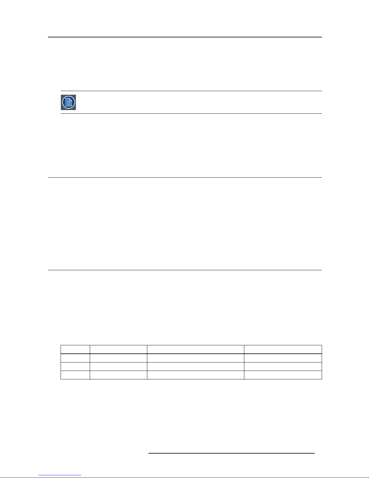
The following table gives a su mm ary of the predefined communication terms.
Header Message body Terminator
Limitations 1 byte N bytes 1 byte
Definition ASCII colon : Mnemonic Modifier Value Target Carriage Return (Hex 0x0D)
Example
:
POWR1
CR
Header
The header informs the projector (in case of transmission) or the computer (in case of reception) that a new data transfer will take
place.
Message body
The message body defines the action to be performed. The message body is built up of several fields:
601–0381–00 F(L)35, FS35 IR, F85 21/10/2015
3
Page 8
2. Communication protocol definitions
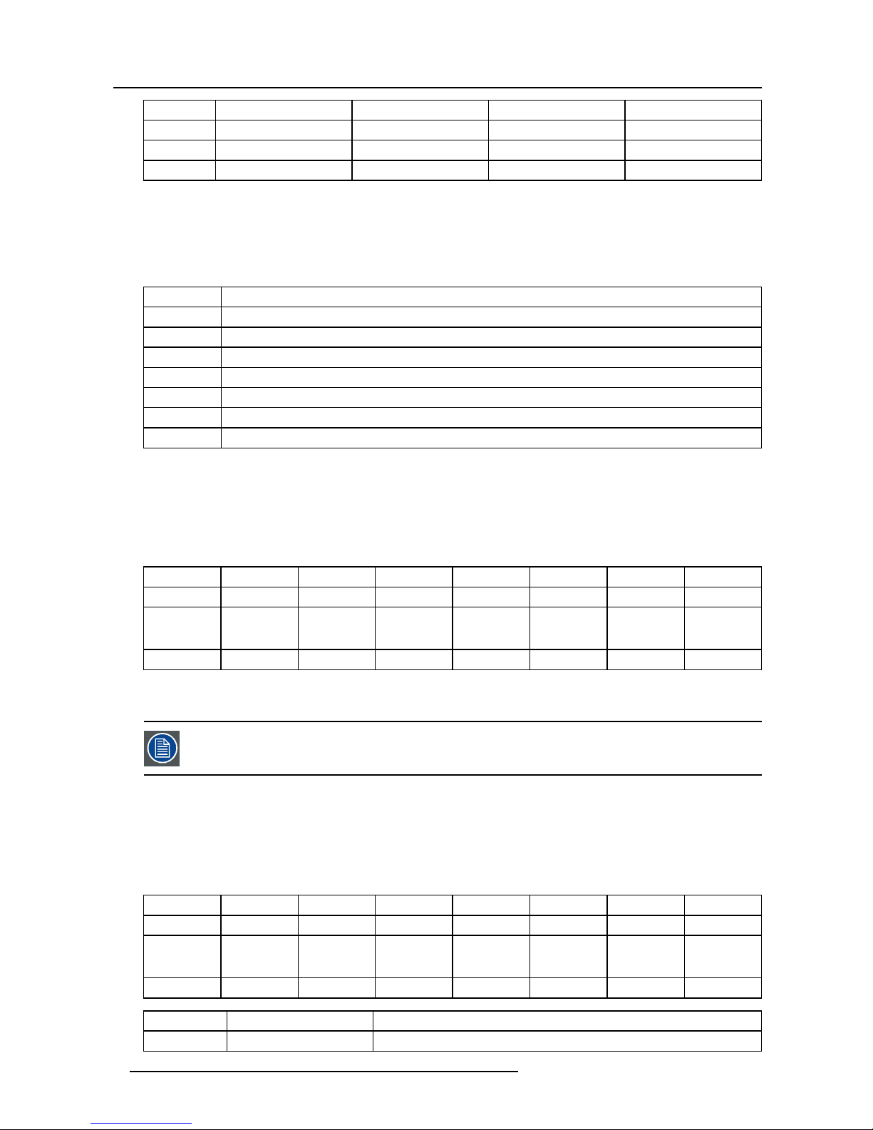
Mnemonic
Modifier
Value Target
Limitations 4 bytes 1 byte N bytes, m ax 6 bytes N bytes, max 4
Inclusion Required
Optional Optional Optional
Example
POWR
A
1
CR
Mnemonic bytes (4 bytes)
The mnemonic is a 4 byte AS CII command (key identifier). This is required in all serial communications.
Modifier byte (1–2 bytes)
The modifier is used to constrain or modify the mne monic command.
Modifier
Description
R
Relative change. Given value will be relative to existing value. e.g. BRIG10 will increase brightness by 10 steps.
A
Not normally used. Manually request acknowledgement/read back the result of the command.
? Get curren t value
?M Get ma ximum value
?N Get m inimum value
?D Get default value
?S Get default step value
Termi n a tor
The terminator informs the projector (in case of transmission) or the computer (in case of reception) that the data trans fer is complete
and that the interpretation of the command and data bytes can start.
Acknowledgement
If the command is understood by the projector then an ’ACK’ command is sent back. The ’ACK’ command uses the following protocol:
Ack. Address
Separator Command Separator
Valu e Term inato r
Limitations 1 byte 1–3 bytes 1 byte 4 bytes 1 byte 6 bytes 1 byte
Definition ASCII %
Projector
address
ASCII space
Mnemonic
ASCII space
Numeric
value
Carriage
Return (Hex
0x0D)
Example
%
001
Space POWR Space
000001
CR
Some commands could return a value that is more than 6 bytes, for exam ple, strings. This is identified by the acknowledgement
including the alphanumeric value ’eXXXXX’.
Address functionality is no longer used. Addres
s bytes will always be 001.
For ex ample:
> :seri ?
> %001 SERI e00001 07010001
Invalid command
If the input com mand is not valid, then the projector acknowledgement may include an er ror message in the value field.
Ack. Address Separator Command Separator Value Terminator
Limitations 1 byte 1–3 bytes 1 byte 4 bytes 1 byte 6 bytes 1 byte
Definition ASCII % Projector
address
ASCII space Mnemonic ASCII space Numeric
value of error
Carriage
Return (Hex
0x0D)
Example
%
001
Space POWR Space
!00001
CR
Error code Error message Description
!00001 Access denied
User does not have sufficient ac cess rights to pe rform this command.
4 601–0381–00 F(L)35, FS35 IR, F85 21/10/2015
Page 9

2. Communication protocol definitions
Error code Error message Description
!00002 Not available
Logic conflict prevents command being available. For example, contrast is not
available when the projector is searching for sources.
!00003 Not implemented
Command not available for this projector configuration. See relevant comments
section in ASCII commands for information.
!00004
Value out of range
Value is not within valid range.
2.3 Examples
SET commands
Command
Description
:POWR1’CR’
Set power on
%001 POWR 000001’CR’
Acknowledge power on
Command
Description
:BRIG 60’CR’
Set brightness to 60
%001 BRIG 000060’CR’
Acknowledge brightness
Command
Description
:CNTR R1’CR’
Increase contrast
%001 CNTR 000061’CR’
Acknowledge increase contrast
Command
Description
:CNTR R-2’CR’
Decrease contrast
%001 CNTR 000059’CR’
Acknowledge decrease contrast
SET commands with target
Command Description
:TATB 1 3’CR’
Set aspect trigger behavior 16:10 to off
%001 TATB 000001’CR’
Acknowledge set aspect trigger behavior 16:10 to off
GET commands
Command
Description
:CNTR?’CR’
Get current value contrast
%001 CNTR 000059’CR’
Acknowledge get current value contrast
Command
Description
:BRIG ?N’CR’
Get minimum value brightness
%001 CNTR 000000’CR’
Acknowledge get minimum value brightness
GET commands with target
Command
Description
:TATB ? 3
Get aspect trigger behavior 16:10
%001 TATB 000001 ’CR’
Acknowledge get aspect trigger behavior 16:10
601–0381–00 F(L)35, FS35 IR, F85 21/10/2015 5
Page 10

Command
Description Platforms
Operations
supported
Level Value Target
Comments
POWR
Power GP3, GP4
Get, Set
End User 0 - power off, 1 - power on
POST
Power state GP3, GP4
Get
End User See value table POST
IABS
Set source abs values GP3, GP4
Get, Set
End User See value table IABS
IDVI
Select DVI GP3, GP4
Get, Set
End User 1 - DVI 1, 2 - DVI 2
IHDM
Select HDMI GP3, GP4
Get, Set
End User 1 - HDMI 1, 2 - HDMI 2
IVGA
Select VGA GP3, GP4
Get, Set
End User 1 - VGA 1, 2 - VGA 2
IDHD
Select dual head DVI GP3, GP4
Get, Set
End User
IDHH
Select dual head HDMI GP3, GP4
Get, Set
End User
IDHX
Select dual head XP2 GP3, GP4
Get, Set
End User
IXP2
Select XP2 GP3, GP4
Get, Set
End User
IYPP
Select component GP3, GP4
Get, Set
End User
ISTS
Signal Status GP3, GP4
Get
End User
0 - searching 1 - locked to
source
BRIG
Brightness GP3, GP4
Get, Set
End User
CNTR
Contrast GP3, GP4
Get, Set
End User
CSAT
Saturation GP3, GP4
Get, Set
End User
PRST
Picture Reset GP3, GP4
Get, Set
End User
PMUT
Picture Mute GP3, GP4
Get, Set
End User 0 - disable, 1 - enable
SABS
Set Scaling abs value GP3, GP4
Get, Set
End User See value table SABS
S1T1
Select Scaling 1:1 GP3, GP4
Get, Set
End User
S169
Select Scaling 16:9 GP3, GP4
Get, Set
End User
SS43
Select Scaling 4:3 GP3, GP4
Get, Set
End User
SFLA
Select Scaling Fill All GP3, GP4
Get, Set
End User
SFAR
Select Scaling Fill Aspect Ratio GP3, GP4
Get, Set
End User
S235
Select Scaling Fill 2.35:1 GP3, GP4
Get, Set
End User
SANL
Select Scaling Anamorphic Lens GP3, GP4
Get, Set
End User
AUTO
Auto adjust current source GP3, GP4
Set
End User
FRZE
Freeze Image GP3, GP4
Get, Set
End User 0 - disable, 1 - enable
GAFI
Select Gamma Film GP3, GP4
Get, Set
End User 1 - Film 1, 2 - Film 2
GAVI
Select Gamma Video GP3, GP4
Get, Set
End User 1 - Video 1, 2 - Video2
GACO
Select Gamma Computer GP3, GP4
Get, Set
End User 1 - Computer 1, 2 - Computer
2
GABS
Set Gamma abs value GP3, GP4
Get, Set
End User See value table GABS
CTWP
Color Management Processed
Test Patterns
GP3, GP4
Get, Set
End User
RCMN
Color management Reset to
Native
GP3, GP4
Set
End User
RWHN
Color Management reset white to
native
GP3, GP4
Set
End User
ACAL
AD calibration GP3, GP4
Set
End User
Picture->Calibration
Picture
Picture->RealColor
Source selection
Power
3. ASCII Command Sets
601-0381-00_GP3/GP4
Sicilium_1_24
6
Page 11

HPOS
Horizontal positon GP3, GP4
Get, Set
End User Only for analog sources
VPOS
Vertical position GP3, GP4
Get, Set
End User Only for analog sources
FREQ
Frequency GP3, GP4
Get, Set
End User Only for analog sources
PHSE
Phase GP3, GP4
Get, Set
End User Only for analog sources
DCSP
Color Space GP3, GP4
Get, Set
End User
0 - auto, 1 - RGB, 2 - REC
709, 3 - REC 601
DVST
Input Level GP3, GP4
Get, Set
End User
0 - auto, 1 - computer, 2 video
CTYP
Input Cropping Mode GP3
Get, Set
End User
0 - Disabled, 1 - Auto, 2 -
2.35:1, 3 - Manual
COFF
Select Input Cropping Mode
Disabled
GP3
Get, Set
End User
CAUT
Select Input Cropping Mode Auto GP3
Get, Set
End User
C235
Select Input Cropping Mode
2.35:1
GP3
Get, Set
End User
CMAN
Select Input Cropping Mode
Manual
GP3
Get, Set
End User
CTOP
Input Cropping Top GP3
Get, Set
End User 35 - input image height
CBTM
Input Cropping Bottom GP3
Get, Set
End User 35 - input image height
BCCR
BrilliantColor Control GP3
Get, Set
End User See value table BCCR
BCEN
BrilliantColor Enable GP3
Get, Set
End User 0 - disable, 1- enable
CMOD
Color Management Enable GP3, GP4
Get, Set
End User 0 - disable, 1- enable
CMWH
Color Management White GP3, GP4
Get, Set
End User 0 - temperature, 1 - coordinate
CMXV
Color Management X-Coordinate
GP3, GP4
Get, Set
End User
CMYV
Color Management Y-Coordinate
GP3, GP4
Get, Set
End User
CMTV
Color Management Temperature GP3, GP4
Get, Set
End User 3200 - 9300
RD65
Reset to D65 GP3, GP4
Set
End User
DSCR
Desired Coords Mode GP3, GP4
Get, Set
End User See value table DSCR
BAGA
Balanced Gains GP3, GP4
Get, Set
End User 0 - disable, 1- enable
DSRX
Desired Red X GP3, GP4
Get, Set
End User
DSRY
Desired Red Y GP3, GP4
Get, Set
End User
DSRG
Desired Red Gain GP3, GP4
Get, Set
End User
DSGX
Desired Green X GP3, GP4
Get, Set
End User
DSGY
Desired Green Y GP3, GP4
Get, Set
End User
DSGG
Desired Green Gain GP3, GP4
Get, Set
End User
DSBX
Desired Blue X GP3, GP4
Get, Set
End User
DSBY
Desired Blue Y GP3, GP4
Get, Set
End User
DSBG
Desired Blue Gain GP3, GP4
Get, Set
End User
DSCX
Desired Cyan X GP3, GP4
Get, Set
End User
DSCY
Desired Cyan Y GP3, GP4
Get, Set
End User
DSCG
Desired Cyan Gain GP3, GP4
Get, Set
End User
DSMX
Desired Magenta X GP3, GP4
Get, Set
End User
DSMY
Desired Magenta Y GP3, GP4
Get, Set
End User
DSMG
Desired Magenta Gain GP3, GP4
Get, Set
End User
DSYX
Desired Yellow X GP3, GP4
Get, Set
End User
DSYY
Desired Yellow Y GP3, GP4
Get, Set
End User
Picture->RealColor
Picture->Advanced
Picture->Advanced->Input Cropping
3. ASCII Command Sets
601-0381-00_GP3/GP4
Sicilium_1_24
8
Page 12

DSYG
Desired Yellow Gain GP3, GP4
Get, Set
End User
DSWG
Desired White Gain GP3, GP4
Get, Set
End User
DFRX
Factory Desired Red X GP3, GP4
Get, Set
Manufacturing
DFRY
Factory Desired Red Y GP3, GP4
Get, Set
Manufacturing
DFRG
Factory Desired Red Gain GP3, GP4
Get, Set
Manufacturing
DFGX
Factory Desired Green X GP3, GP4
Get, Set
Manufacturing
DFGY
Factory Desired Green Y GP3, GP4
Get, Set
Manufacturing
DFGG
Factory Desired Green Gain GP3, GP4
Get, Set
Manufacturing
DFBX
Factory Desired Blue X GP3, GP4
Get, Set
Manufacturing
DFBY
Factory Desired Blue Y GP3, GP4
Get, Set
Manufacturing
DFBG
Factory Desired Blue Gain GP3, GP4
Get, Set
Manufacturing
DFCX
Factory Desired Cyan X GP3, GP4
Get, Set
Manufacturing
DFCY
Factory Desired Cyan Y GP3, GP4
Get, Set
Manufacturing
DFCG
Factory Desired Cyan Gain GP3, GP4
Get, Set
Manufacturing
DFMX
Factory Desired Magenta X GP3, GP4
Get, Set
Manufacturing
DFMY
Factory Desired Magenta Y GP3, GP4
Get, Set
Manufacturing
DFMG
Factory Desired Magenta Gain GP3, GP4
Get, Set
Manufacturing
DFYX
Factory Desired Yellow X GP3, GP4
Get, Set
Manufacturing
DFYY
Factory Desired Yellow Y GP3, GP4
Get, Set
Manufacturing
DFYG
Factory Desired Yellow Gain GP3, GP4
Get, Set
Manufacturing
DFWG
Factory Desired White Gain GP3, GP4
Get, Set
Manufacturing
MSRX
Measured Red X GP3, GP4
Get, Set
End User
MSRY
Measured Red Y GP3, GP4
Get, Set
End User
MSRL
Measured Red Luminance GP3, GP4
Get, Set
End User
MSGX
Measured Green X GP3, GP4
Get, Set
End User
MSGY
Measured Green Y GP3, GP4
Get, Set
End User
MSGL
Measured Green Luminance GP3, GP4
Get, Set
End User
MSBX
Measured Blue X GP3, GP4
Get, Set
End User
MSBY
Measured Blue Y GP3, GP4
Get, Set
End User
MSBL
Measured Blue Luminance GP3, GP4
Get, Set
End User
MSWX
Measured White X GP3, GP4
Get, Set
End User
MSWY
Measured White Y GP3, GP4
Get, Set
End User
MSWL
Measured White Luminance GP3, GP4
Get, Set
End User
MSDX
Measured BC1 X GP3
Get, Set
End User
MSDY
Measured BC1 Y GP3
Get, Set
End User
MSDL
Measured BC1 Luminance GP3
Get, Set
End User
MSEX
Measured BC2 X GP3
Get, Set
End User
MSEY
Measured BC2 Y GP3
Get, Set
End User
MSEL
Measured BC2 Luminance GP3
Get, Set
End User
MFRX
Factory Measured Red X GP3, GP4
Get, Set
Manufacturing
MFRY
Factory Measured Red Y GP3, GP4
Get, Set
Manufacturing
MFRL
Factory Measured Red
Luminance
GP3, GP4
Get, Set
Manufacturing
MFGX
Factory Measured Green X GP3, GP4
Get, Set
Manufacturing
MFGY
Factory Measured Green Y GP3, GP4
Get, Set
Manufacturing
MFGL
Factory Measured Green
Luminance
GP3, GP4
Get, Set
Manufacturing
3. ASCII Command Sets
601-0381-00_GP3/GP4
Sicilium_1_24
9
Page 13

MFBX
Factory Measured Blue X GP3, GP4
Get, Set
Manufacturing
MFBY
Factory Measured Blue Y GP3, GP4
Get, Set
Manufacturing
MFBL
Factory Measured Blue
Luminance
GP3, GP4
Get, Set
Manufacturing
MFWX
Factory Measured White X GP3, GP4
Get, Set
Manufacturing
MFWY
Factory Measured White Y GP3, GP4
Get, Set
Manufacturing
MFWL
Factory Measured White
Luminance
GP3, GP4
Get, Set
Manufacturing
MFDX
Factory Measured BC1 X GP3
Get, Set
Manufacturing
MFDY
Factory Measured BC1 Y GP3
Get, Set
Manufacturing
MFDL
Factory Measured BC1
Luminance
GP3
Get, Set
Manufacturing
MFEX
Factory Measured BC2 X GP3
Get, Set
Manufacturing
MFEY
Factory Measured BC2 Y GP3
Get, Set
Manufacturing
MFEL
Factory Measured BC2
Luminance
GP3
Get, Set
Manufacturing
CMTP
Color Management Test Patterns GP3, GP4
Get, Set
End User
IBCO
Individual brightness and contrast
offset adjustments
GP3, GP4
Get, Set
End User 0 - disable, 1 - enable
0-RGB, 1-IR
(if available)
BOR0
Brightness offset red GP3, GP4
Get, Set
End User
BOG0
Brightness offset green GP3, GP4
Get, Set
End User
BOB0
Brightness offset blue GP3, GP4
Get, Set
End User
COR0
Contrast offset red GP3, GP4
Get, Set
End User
COG0
Contrast offset green GP3, GP4
Get, Set
End User
COB0
Contrast offset blue GP3, GP4
Get, Set
End User
DESK
Select orientation - Desktop Front GP3, GP4
Get, Set
End User
CEIL
Select orientation - Ceiling Front GP3, GP4
Get, Set
End User
RDES
Select orientation - Desktop Rear GP3, GP4
Get, Set
End User
RCEI
Select orientation - Ceiling Rear GP3, GP4
Get, Set
End User
ORIE
Select orientation - Absolute
value
GP3, GP4
Get, Set
End User See value table ORIE
SCAN
Source Scan GP3, GP4
Get, Set
End User 0 - disable, 1 - enable
IR01
IR Enable 1 GP3, GP4
Get, Set
End User 0 - disable, 1 - enable
IR02
IR Enable 2 GP3, GP4
Get, Set
End User 0 - disable, 1 - enable
IR03
IR Enable 3 GP3
Get, Set
End User 0 - disable, 1 - enable
OSDC
OSD Enable GP3, GP4
Get, Set
End User See value table OSDC
TEST
Test Image GP3, GP4
Get, Set
End User 0 - 7 different test patterns
DHED
Dual Head Setup Mode GP3, GP4
Get, Set
End User 0 - off, 1 - side by side
SVGA
Sync termination VGA GP3, GP4
Get, Set
End User 0 - 2.2kOhm, 1 - 75Ohm
SNCL
Sync level VGA GP3, GP4
Get, Set
End User 0-255
SNCS
Sync Level SOG GP3, GP4
Get, Set
End User 0-31 Infitec only
OPFI
Infitec filter GP3
Get, Set
End User 0 - disable, 1 - enable Infitec only
CSCC
Infitec CSC GP3
Get, Set
End User 0 - disable, 1 - enable
EDIR
Edit resolution GP3, GP4
Get, Set
End User See value table EDIR
EDIT
Edid type GP3, GP4
Get, Set
End User See value table EDIT
Installation
Picture->Advanced->Source Correction
3. ASCII Command Sets
601-0381-00_GP3/GP4
Sicilium_1_24
10
Page 14

ECOM
Eco Mode GP3, GP4
Get, Set
End User 0 - disable, 1 - enable
LPW1
Lamp1 Power GP3, GP4
Get, Set
End User
LPW2
Lamp2 Power GP3, GP4
Get, Set
End User
LMOD
Lamp Mode GP3, GP4
Get, Set
End User See value table LMOD
LDLY
Lamp Auto Switch Delay GP3, GP4
Get, Set
End User
LPW1
LED Power GP3
Get, Set
End User
DBDI
LED Power GP3 LED
Get, Set
End User
Use LPW1, this is for legacy
support
LDMM
LED Dim Mode GP3 LED
Get, Set
End User 0 - standard, 1 - custom
LDCR
LED Dim Custom Red GP3 LED
Get, Set
End User
LDCG
LED Dim Custom Green GP3 LED
Get, Set
End User
LDCB
LED Dim Custom Blue GP3 L ED
Get, Set
End User
TRG1
Trigger 1 Mode GP3, GP4
Get, Set
End User See value table TRGx
TRG2
Trigger 2 Mode GP3, GP4
Get, Set
End User See value table TRGx
TATB
Aspect Trigger Behavior GP3, GP4
Get, Set
End User See value table TATB
See value
table TATB
FLSO
Frame lock Source GP3, GP4
Get, Set
End User 0 - Internal, 1 - External
FLOS
Frame lock Output Signal GP3, GP4
Get, Set
End User
0 - Off , 1 - Frame lock, 2 -
Pass-through
FLST
Frame lock Status GP3, GP4
Get
End User
Print current frame lock status
TSLR
3D source L/R sync GP3, GP4
Get, Set
End User 0 - None, 1 - BNC sync-in
TDLR
3D display L/R sync GP3, GP4
Get, Set
End User 0 - None, 1 - BNC sync-in
TBOS
3D BNC sync-out signal See value table TBOS
FCRE
Factory Reset GP3, GP4
Set
End User
FCRL
Factory reset level GP3, GP4
Get, Set
Power User 0 - limited, 1 - full
PINC
PIN Code GP3, GP4
Set
End User
Must be executed in standby
CODE
Service Code GP3, GP4
Set
Power User
RCID
RCID Internal GP3, GP4
Get, Set
End User
DPMS
DPMS GP3, GP4
Get, Set
End User 0 - disable, 1 - enable
DPMT
DPMS Timeout GP3, GP4
Get, Set
End User
KEYB
Backlight Timeout GP3, GP4
Get, Set
End User
MNUT
Menu Timeout GP3, GP4
Get, Set
End User
BACK
Background color GP3, GP4
Get, Set
End User
SPLH
Splash GP3, GP4
Get, Set
End User
LMUT
LED indicators mute GP3, GP4
Get, Set
End User 0 - off, 1 - on
BAUD
Baud rate GP3, GP4
Get, Set
End User See value table BAUD
Installation->Trigger
Settings
Installation->Frame lock setup
Installation->LED
Installation->Lamp
3. ASCII Command Sets
601-0381-00_GP3/GP4
Sicilium_1_24
11
Page 15

RTCH
Real Time Clock Hour GP3, GP4
Get, Set
End User
RTCM
Real Time Clock Minute GP3, GP4
Get, Set
End User
RTCS
Real Time Clock Second GP3, GP4
Get, Set
End User
RTCD
Real Time Clock Day GP3, GP4
Get, Set
End User
RTCN
Real Time Clock Month GP3, GP4
Get, Set
End User
RTCY
Real Time Clock Year GP3, GP4
Get, Set
End User
RTCW
Real Time Clock Day of Week GP3, GP4
Get
End User
UMST
Store profile GP3, GP4
Set
End User Profile number (0 - 9)
UMRC
Recall profile GP3, GP5
Set
End User Profile number (0 - 9)
TDSM
Stereo Mode GP3 120Hz, GP4
Get, Set
End User See value table TDSM
TDGT
Glass type GP3 120Hz, GP4
Get, Set
End User
0 - DLP Link™, 1 - IR, 2 - IR
high brightness
TDGD
Genlock phase delay GP3 120Hz, GP4
Get, Set
End User
TDSE
Swap eyes GP3 120Hz, GP4
Get, Set
End User 0 - off, 1 - on
AUXL
Full spectrum mode enable GP3 LED IR
Get, Set
End User 0 - disable, 1 - enable
DISL
RGB LEDs enable GP3 LED IR
Get, Set
End User 0 - disable, 1 - enable
LDMM
LED Dim Mode GP3 LED IR
Get, Set
End User 0 - standard, 1 - custom
LPW1
LED Power GP3
Get, Set
End User
LDCR
LED Dim Custom Red GP3 LED IR
Get, Set
End User
LDCG
LED Dim Custom Green GP3 L ED IR
Get, Set
End User
LDCB
LED Dim Custom Blue GP3 LED IR
Get, Set
End User
IBCO
Individual brightness and contrast
offset adjustments
GP3, GP4
Get, Set
End User 0 - disable, 1 - enable
0-RGB, 1-IR
(if available)
BOR0
Brightness offset red GP3 LED IR
Get, Set
End User
BOG0
Brightness offset green GP3 LED IR
Get, Set
End User
BOB0
Brightness offset blue GP3 LED IR
Get, Set
End User
COR0
Contrast offset red GP3 LED IR
Get, Set
End User
COG0
Contrast offset green GP3 LED IR
Get, Set
End User
COB0
Contrast offset blue GP3 LED IR
Get, Set
End User
IR control->RGB adjustments
IR control
Stereo
Profiles
Settings->Set date and time
3. ASCII Command Sets
601-0381-00_GP3/GP4
Sicilium_1_24
12
Page 16

AUXD
IR LED power GP3 LED IR
Get, Set
End User
GAB1
Set Gamma abs value IR channel
GP3 LED IR
WUXGA
Get, Set
End User See value table GABS
SCMP
sub channel mapping
GP3 LED IR
WUXGA and
Get, Set
End User
0 - RGB->RGB, 1 - R->RGB, 2
- G->RGB, 3 - B->RGB
IBCO
Individual brightness and contrast
offset adjustments
GP3, GP4
Get, Set
End User 0 - disable, 1 - enable
0-RGB, 1-IR
(if available)
BOR1
Brightness offset red
GP3 LED IR
WUXGA
Get, Set
End User
BOG1
Brightness offset green
GP3 LED IR
WUXGA
Get, Set
End User
BOB1
Brightness offset blue
GP3 LED IR
WUXGA
Get, Set
End User
COR1
Contrast offset red
GP3 LED IR
WUXGA
Get, Set
End User
COG1
Contrast offset green
GP3 LED IR
WUXGA
Get, Set
End User
COB1
Contrast offset blue
GP3 LED IR
WUXGA
Get, Set
End User
IRFI
IR Filter enable GP3 LED IR MKII
Get, Set
End User
FOIN
Focus In GP3, GP4
Set
End User 1 - Slow, 2 - Medium, 3 - Fast
FOUT
Focus Out GP3, GP4
Set
End User 1 - Slow, 2 - Medium, 3 - Fast
ZOIN
Zoom In GP3, GP4
Set
End User 1 - Slow, 2 - Medium, 3 - Fast
ZOUT
Zoom Out GP3, GP4
Set
End User 1 - Slow, 2 - Medium, 3 - Fast
IROP
Iris Open GP3, GP4
Set
End User 1 - Slow, 2 - Medium, 3 - Fast
IRCL
Iris Close GP3, GP4
Set
End User 1 - Slow, 2 - Medium, 3 - Fast
LSDW
Lens Shift Down GP3, GP4
Set
End User 1 - Slow, 2 - Medium, 3 - Fast
LSUP
Lens Shift Up GP3, GP4
Set
End User 1 - Slow, 2 - Medium, 3 - Fast
LSLF
Lens Shift Left GP3, GP4
Set
End User 1 - Slow, 2 - Medium, 3 - Fast
LSRH
Lens Shift Right GP3, GP4
Set
End User 1 - Slow, 2 - Medium, 3 - Fast
SHUT
Shutter GP3, GP4
Set
End User 0 - disable, 1 - enable
LENS
Lens ID GP3, GP4
Get
End User
LMON
Lens Monitoring GP3, GP4
Get, Set
Power User 0 - disable, 1 - enable
ZOPO
Zoom position GP3, GP4
Get, Set
End User
FOPO
Focus position GP3, GP4
Get, Set
End User
IRPO
Iris position GP3, GP4
Get, Set
End User
LRM1
Lamp1 Estimated Remaining
Lamp Time
GP3, GP4
Get
End User
LTR1
Lamp1 Runtime GP3, GP4
Get
End User
LHO1
Lamp Channel 1 Total Time GP3, GP4
Get
End User
See value table LST1 and
LST2
LST1
Lamp1 Status GP3, GP4
Get
End User
LRM2
Lamp2 Estimated Remaining
Lamp Time
GP3, GP4
Get
End User
LTR2
Lamp2 Runtime GP3, GP4
Get
End User
LHO2
Lamp Channel 2 Total Time GP3, GP4
Get
End User
See value table LST1 and
LST2
LST2
Lamp2 Status GP3, GP4
Get
End User
UTOT
Unit Time Total GP3, GP4
Get
End User
Lamp status
Lens control
IR control->IR adjustments
3. ASCII Command Sets
601-0381-00_GP3/GP4
Sicilium_1_24
13
Page 17

MENU
Menu Navigate Toggle OSD
Menu
GP3, GP4
Set
End User
NVUP
Menu Navigate Up GP3, GP4
Set
End User
NVDW
Menu Navigate Down GP3, GP4
Set
End User
NVLF
Menu Navigate Left GP3, GP4
Set
End User
NVRH
Menu Navigate Right GP3, GP4
Set
End User
NVOK
Menu Navigate Ok GP3, GP4
Set
End User
ECHO
Communication Response
(on/off)
GP3, GP4
Set
End User
LANG
Language GP3, GP4
Get, Set
End User
SINF
Show OSD Info GP3, GP4
Set
End User
CWI1
Color Wheel Index 1 GP3
Get, Set
Power User
CWI2
Color Wheel Index 2 GP3
Get, Set
Power User
CRST
Reset All Counters GP3, GP4
Set
Manufacturing
MAYR
Manufacture Year GP3, GP4
Get
Manufacturing
MAWE
Manufacture Week GP3, GP4
Get
Manufacturing
LFMP
LFM Performed GP3, GP4
Set
Power User
GPEN
Enable Power User Gammas GP3, GP4
Get, Set
Power User
AFCL
AD Factory Calibrate GP3, GP4
Set
Manufacturing
LSDI
Lens shift disable GP3, GP4
Get, Set
Power User 0 - enable 1 - disable
BCPE
Enable Power User brilliant color
modes
GP3
Get, Set
Power User 0 - enable 1 - disable
STRS
Skip reset timeout (mirror
exercise)
GP3
Get, Set
Manufacturing
0 - do not skip 1 - skip
(WQXGA only)
CALM
LED Calibration mode GP3 LED
Get, Set
Power User 0 - disable, 1 - enable
LVCA
LED voltage calibration start GP3 LED
Set
Service Partner
LVCS
LED voltage calibration status GP3 LED
Get
Service Partner
0 - done, 1 - in progress, 2 failed
LVCE
LED voltage calibration error
code
GP3 LED
Get
Service Partner
bit wise error code see value
table LVCE
LIVR
LED input voltage red GP3 LED
Get
Service Partner
LIVG
LED input voltage green GP3 LED
Get
Service Partner
LIVB
LED input voltage blue GP3 LED
Get
Service Partner
LDVR
LED drop out voltage red GP3 LED
Get
Service Partner
LDVG
LED drop out voltage green GP3 LED
Get
Service Partner
LDVB
LED drop out voltage blue GP3 LED
Get
Service Partner
UINV
Update internal sensor values
factory
GP3 LED
Set
Manufacturing
UIVU
Update internal sensor values
user
GP3 LED
Set
Power User
INCS
Internal sensor calibration status GP3 LED
Get
Power User
0 - done, 1 - in progress, 2 failed
INCE
Internal sensor calibration error
code
GP3 LED
Get
Power User
bit wise error code see value
table INCE
INTR
Internal sensor value red GP3 LED
Get
Power User
INTG
Internal sensor value green GP3 LED
Get
Power User
INTB
Internal sensor value blue GP3 LED
Get
Power User
INDR
Internal sensor duration value red GP3 LED
Get
Power User
Menu navigate
Miscellaneous
Service->LED calibration
Service
3. ASCII Command Sets
601-0381-00_GP3/GP4
Sicilium_1_24
14
Page 18

INDG
Internal sensor duration value
green
GP3 LED
Get
Power User
INDB
Internal sensor duration value
blue
GP3 LED
Get
Power User
THRM
Thermal Status GP3, GP4
Get
Power User
FAN1
Fan Speed 1 GP3, GP4
Get
Power User
FAN2
Fan Speed 2 GP3, GP4
Get
Power User
FAN3
Fan Speed 3 GP3, GP4
Get
Power User
FAN4
Fan Speed 4 GP3, GP4
Get
Power User
FAN5
Fan Speed 5 GP3, GP4
Get
Power User
FAN6
Fan Speed 6 GP3, GP4
Get
Power User
FAN7
Fan Speed 7 GP3, GP4
Get
Power User
FAN8
Fan Speed 8 GP3, GP4
Get
Power User
SNS1
Sensor Value 1 GP3, GP4
Get
Power User
SNS2
Sensor Value 2 GP3, GP4
Get
Power User
SNS3
Sensor Value 3 GP3, GP4
Get
Power User
SNS4
Sensor Value 4 GP3, GP4
Get
Power User
SNS5
Sensor Value 5 GP3, GP4
Get
Power User
SNS6
Sensor Value 6 GP3, GP4
Get
Power User
SNS7
Sensor Value 7 GP3, GP4
Get
Power User
SNS8
Sensor Value 8 GP3, GP4
Get
Power User
PLAT
Platform Name String GP3, GP4
Get
Power User
Extended Protocol
SERI
Serial Number String GP3, GP4
Get
Power User
Extended Protocol
MODL
Model Name String GP3, GP4
Get
Power User
Extended Protocol
PART
Part Number String GP3, GP4
Get
Power User
Extended Protocol
SVER
Software Version GP3, GP4
Get
Power User
Extended Protocol
PRID
Product ID GP3, GP4
Get
Power User
ACSS
Current Access Level GP3, GP4
Get
End User
MACA
MAC address GP3, GP4
Get
End User
Extended Protocol
IPAD
IP address GP3, GP4
Get
End User See value table LEST
LEST
Indicator LED state GP3, GP4
Get
End User
Extended Protocol
SWSN
SVN SW Revision GP3, GP4
Get
Power User
FLFS
Frame lock(2D) frequency GP3, GP4
Get
End User See value table FLSS
FLSS
Frame lock(2D) status GP3, GP4
Get
End User
TDFS
3D LR frequency GP3, GP4
Get
End User
TDDS
3D LR duty cycle GP3, GP4
Get
End User See value table TDSS
TDSS
3D LR status GP3, GP4
Get
End User
X1ID
Xport 1 ID GP3, GP4
Get
Manufacturing
X2ID
Xport 2 ID GP3, GP4
Get
Manufacturing
Status
Thermal
3. ASCII Command Sets
601-0381-00_GP3/GP4
Sicilium_1_24
15
Page 19

LMBX
Lamp data mailbox GP3
Get, Set
Manufacturing Data
0 - Lamp 1, 1
- Lamp 2
LMBP
Lamp data mailbox position GP3
Get, Set
Manufacturing Data
0 - Lamp 1, 1
- Lamp 2
LMBC
Lamp data mailbox checksum GP3
Get, Set
Manufacturing Data
0 - Lamp 1, 1
- Lamp 2
Lamp data
3. ASCII Command Sets
601-0381-00_GP3/GP4
Sicilium_1_24
16
Page 20

Value tables
IABS
Set source abs values
Value Description
0 VGA 1
1 VGA 2
2 DVI 1
7 Component
8 HDMI 1
10 DVI 2
11 HDMI 2
12 Dual Head DVI
13 Dual Head HDMI
14 Dual Head XP2
15 XP2 A
16 XP2 B
SABS
Set scaling abs values
Value Description
0 1:1
1 Fill All
2 Fill Aspect Ratio
3 Fill 16:9
4 Fill 4:3
5 Fill 2.35:1
11 Anamorphic Lens
LST1 and LST2
Lamp status
Value Description
0 Defect
1 Warming up
2 Lamp is on
3 Lamp is off
4 Lamp is cooling down
5 Lamp is not present
GABS
Set Gamma abs value
Value Description
0 Film 2.2
1 Film 2.8
2 Video 1
3 Video 2
4 Film 2.4
5 Film 2.6
7 Computer 1
8 Computer 2
9 Linear (when available)
10 AD calibration (when available)
11 DICOM (when available)
12 DICOM ambient 10 LUX (when available)
13 DICOM ambient 60 LUX (when available)
14 DICOM ambient 180 LUX (when available)
15 DICOM ambient 250 LUX (when available)
16 DICOM ambient 300 LUX (when available)
17 DICOM ambient 400 LUX (when available)
20 Custom 1 (when available)
21 Custom 2 (when available)
22 Dynamic (when available)
3. ASCII Command Sets
601-0381-00_GP3/GP4
Sicilium_1_24
17
Page 21

DSCR
Desired Coords Mode
Value Description
0 Off
1 RGB
2 RGBCMY
ORIE
Select Orientation abs value
Value Description
0 Desktop front
1 Ceiling rear
2 Desktop rear
3 Ceiling front
OSDC
OSD Enable
Value Description
0 OSD off
1 OSD show only warnings
2 OSD on
LMOD
Lamp Mode
Value Description
0 Single lamp 1
1 Single lamp 2
2 Dual lamps
3 Auto lamp switch
BCCR (WQXGA UHP) BCCR (1080/WUXGA UHP) BCCR (LED)
BrilliantColor Control BrilliantColor Control BrilliantColor Control
Value Description Value Description Value Description
0 Off 0 Off 0 VizSim
1 Computer balanced 1 Video 1 High Brightness
2 Video balanced 2 (SRP Full, when available) 2 SRP 8ms
3 Computer native 3 Computer 3 Graphics
4 Video native 4 (SRP Half, when available) 4 SRP 6ms (when available)
5 (SRP Half, when available) 5 VizSim 180 (when available)
5 (SRP Full, when available) 6 VizSim 100 (when available)
7 VizSim 50 (when available)
8 IR 255 (when available)
9 IR 20 (when available)
POST
Power state
Value Description
0 Deep sleep
1 Off
2 Powering up
3 On
4 Powering down
5 Critical powering down
6 Critical off
7 Start
8 Shutting down
3. ASCII Command Sets
601-0381-00_GP3/GP4
Sicilium_1_24
18
Page 22

LEST
Status LED state
Value Description
0 Green/Blue On
1 Green/Blue Flash
2 Yellow On
3 Yellow Flash
4 Red On
5 Red Flash
DCSP
Digital colorspace
Value Description
0 RGB
1 YPbPr 709
2 YpbPr 601
TRGx
Trigger mode
Value Description
1 On
2 Off
3 Screen
4 Aspect
TATB
Aspect trigger behavior
Target Description Value
0 - 4:3
1 - 5:4 on 0
2 - 16:9 off 1
3 - 16:10 no change 2
4 - 2.35:1
5 - no source
6 - standby
EDIR
Edid resolution
Target Description Value
Auto 0
Custom (not implemented) 1
VGA 2
SVGA 3
XGA 4
720 50Hz 5
720 60Hz 6
WXGA 1366 7
SXGA 8
SX+ 9
1080 deep color 10
1080 standard 11
WUXGA 12
WQXGA (DVI1/2 only) 13
EDIT
Edid type
Target Description Value
DVI 1
HDMI 2
0 - VGA1
3 - HDMI1
14 - HDMI2
1 - VGA2
2 - DVI1
3 - HDMI1
12 - DVI2
14 - HDMI2
3. ASCII Command Sets
601-0381-00_GP3/GP4
Sicilium_1_24
19
Page 23

BAUD
Trigger mode
Value Description
4800 4800
9600 9600
19200 19200
38400 38400
57600 57600
115200 115200
TBOS
3D BNC sync-out signal
Value Description
0 Off
1 3D glass sync
2 3D display sync
3 Passthrough
FLSS
Framelock signal status
Value Description
0 free running
3 locked
TDSS
3D LR Signal status
Value Description
0 free running
1 drifting, free running
2 drifting, locked
3 locked
TDSM
3D stereo mode
Value Description
0 off
1 on
TDSM
3D stereo mode with DCC120 module
Value Description
0 off
1 frame sequential
2 side by side
3. ASCII Command Sets
601-0381-00_GP3/GP4
Sicilium_1_24
20
Page 24

LVCE
bit wise error code for LED voltage calibration
Bit Description
0 Set red input voltage failed
1 Read red ADC current failed
2 Read red drop out voltage failed
3 Desired red input voltage out of range
4 Red loop count exceed max value
10 Set green input voltage failed
11 Read green ADC current failed
12 Read green drop out voltage failed
13 Desired green input voltage out of range
14 Green loop count exceed max value
20 Set blue input voltage failed
21 Read blue ADC current failed
22 Read blue drop out voltage failed
23 Desired blue input voltage out of range
24 Blue loop count exceed max value
INCE
bit wise error code for LED sensor calibration
Bit Description
0 Write red sensor duration failed
1 Read red sensor value failed
2 Red loop count exceed max value
3 Red sensor value out of range
10 Write green sensor duration failed
11 Read green sensor value failed
12 Green loop count exceed max value
13 Green sensor value out of range
20 Write blue sensor duration failed
21 Read blue sensor value failed
22 Blue loop count exceed max value
23 Blue sensor value out of range
3. ASCII Command Sets
601-0381-00_GP3/GP4
Sicilium_1_24
21
 Loading...