

Page 1
F80 series
R5906852/00
21/09/2017
User Manual
Page 2

Registered address: Barco NV
President Kennedypark 35, 8500 Kortrijk, Belgium
Phone: +32 56.23.32.11
Fax: +32 56.26.22.62
Support: www.barco.com/en/support
Visit us at the web: www.barco.com
Barco Fredrikstad AS
Habornveien 53, N-1630 Gamle Fredrikstad, Norway
Phone: +47 6930 4550
Fax: +47 6930 4580
Support: Support.fre@barco.com
Visit us at the web: www.barco.com
Printed in Norway
Page 3

Copyright ©
All rights reserved. No part of this documen t may be copied, reproduced or translated. It shall not otherwise be recorded, transmitted or
stored in a retrieval system without the prior written consent of Barc o.
Changes
Barco p rovides this manual ’as is’ without warranty of any kind, either expressed or implied, including but not limited to the implied war ranties or merchantability and fitness for a particular purpose. Barco m ay make improv ements and/or changes to the product(s) and/or the
program(s) described in this publication at any time without notice.
This publication could contain technical inaccuracies or typographical errors. Changes are periodic
publication; these changes are incorporated in new editions of this publication.
The latest edition of Barco manuals can be downloaded from the Barco web site w
h
ttps://www.barco.com/en/signin.
ww.barco.com or from the secured Barco web site
ally made to the information in this
Trademarks
Brand and product name s mentioned in this manual m ay be trademarks, registered trademarks or copyrights of their respective holders.
All brand and product names mentioned in this manual serve as comments or examples and are not to be understood as advertising for
the products or their manufacturers.
Guarantee and Compensation
Barco provides a guarantee relating to perfect manufacturing as part of the legally stipulated terms of guarantee. On receipt, the purchaser
must immediately inspect all delivered goods for damage incurred during transport, as well as for material and manufacturing faults Barco
must be informed immediately in writing of any complaints.
The period of guarantee begins on the date of transfer of risks, in the case of special systems and software on the date of commissioning,
at latest 30 days after the transfer of risks. In the ev ent of justifie
at its own discretion within an appropriate period. If this measure proves to be impossible or uns uccessful, the purchaser can demand a
reduction in the purchase price or cancellation of the contract. All other claim s, in particular those relating to compensation for direct or
indirect damage, and also damage attributed to the operation o
of the system or independent service, will be deemed invalid provided the damage is not proven to be attributed to the absence of pr operties
guaranteed in writing or due to the intent or gross negligence o r part of Barco.
If the purchaser or a third party carries out modifications or repairs on goods delivered by Barco, or if the goods are ha ndled incorrectly,
in particular if the systems are operated incorrectly or if, after the transfer o f risks, the goods are subjec t to influences not agreed upon in
the contract, all guarantee claims of the purchaser will be rendered invalid. Not included in the guarantee coverage are system failures
which are attributed to programs or special electronic circuitry provided by the purchaser, e.g. interfaces. Normal wear as well as normal
maintenance are not subject to the guarantee provided by Barco either.
The environmental conditions as well as the servicing and maintenance regulations specified in this manual must be complied with by the
customer.
d notice of complaint, Barco can repair the fault or provide a replacement
f software as well as to other services pr ovided by Barco, being a component
Federal Communications Commission (FCC Statement)
This equipment has been tested and found to c omply with the limits for a class A digital device, pursuant to Part 15 of the F CC rules.
These limits are designed to provide reasonable protection against harmful interference when the equipment is operated in a commercial
environment. This equipment generates, uses, and can radiate radio frequency energy and, if not installed and used in accordance with
the instruction manual, may cause harmful interference to radio communications. Operation of this equipm ent in a residential area may
cause harmful interference, in which c ase the user will be responsible for correcting any interference at his own expense
Changes or modific ations not expressly approved by the party responsible for compliance could v oid the user’s authority to ope rate the
equipment
EMC statements
EN55032/CISPR32 Class A MME (MultiMedia Equipment)
Warning : This equipment is compliant with Class A of CISPR 32. In a residential environment this equipment may cause radio interfer-
ence.
Class A ITE (Information Technology Equipment)
Warning : This is a class A product. In a domestic environment this product may cause radio interference in which cas e the user may be
required to take adequate mea
sures.
Page 4

Page 5

Table of contents
TABLE OF CONTENTS
1. Safety................................................................................................................ 3
1.1 General considerations.............................................................................................................. 3
1.2 Important safety instructions ........................................................................................................ 4
1.3 Product safety labels ................................................................................................................ 7
1.4 Risk Group 3 Safety................................................................................................................. 8
1.4.1 General considerations ....................................................................................................... 8
1.4.2 High Brightness precautions: Hazard Distance (HD)........................................................................ 8
1.4.3 HD for fully enclosed projection systems ....................................................................................10
1.4.4 HD in function of the lens Throw Ratio (TR) .................................................................................11
2. Remote Control Unit. ................ ................ ................ ................ ................ .............13
2.1 Remote control, Battery installation................................................................................................. 13
2.2 U sing the XLR connector of the RCU ...............................................................................................14
2.3 Remote control, on/off button .......................................................................................................14
3. Input & Communication..........................................................................................17
3.1 Introduction ..........................................................................................................................17
3.2 Connection Panel . .. .................................................................................................................17
3.3 Making connections ................................................................................................................. 18
3.4 Connector specifications ............................................................................................................18
3.4.1 DVI-I...........................................................................................................................18
3.4.2 Display Port 1.2 ...............................................................................................................19
3.4.3 HDMI 2.0 ......................................................................................................................19
3.4.4 3G-SDI ........................................................................................................................19
3.4.5 HDBase T .....................................................................................................................20
3.5 Controlinterfaces....................................................................................................................20
3.5.1 RS-232 ........................................................................................................................20
3.5.2 LAN/Ethernet.................................................................................................................. 21
3.5.3 USB-A port....................................................................................................................21
3.6 LED and Button indication chart .................................................................................................... 21
4. Getting Started.................. ................ ................ ................ ................ ................ ...23
4.1 Functionality overview ...............................................................................................................23
4.2 Power modes ........................................................................................................................24
4.3 Power mode transitions .............................................................................................................25
4.3.1 General ........................................................................................................................ 25
4.3.2 Poweron projector............................................................................................................25
4.3.3 Going from READY to ON.................................................................................................... 26
4.3.4 Going from ON to READY.................................................................................................... 26
4.3.5 Going from READY to ECO standby.........................................................................................26
4.3.6 Going from ECO to ON .......................................................................................................26
4.4 Status overview......................................................................................................................26
4.5 Power off projector ..................................................................................................................27
4.6 Operation in 24/7 Mode .............................................................................................................27
4.7 Using the RCU....................................................................................................................... 28
4.8 Projector Address....................................................................................................................29
4.8.1 Controlling the projector ......................................................................................................29
4.8.2 Displaying and Programming addresses into the RCU . . ....................................................................30
4.9 Quick setup via Direct access....................................................................................................... 30
5. Graphic User Interface (GUI) ....................................................................................33
5.1 Overview.............................................................................................................................33
5.2 Navigation ........................................................................................................................... 33
5.3 Test Patterns......................................................................................................................... 34
6. GUI – Source .......... ................ ................ ................ ................ ................ .............37
6.1 Source Selection ....................................................................................................................37
6.2 C onnector Settings ..................................................................................................................37
7. GUI – Image ... ................ ................ ................ ................ .................. ................ ...39
7.1 Setting image levels m anually ......................................................................................................39
7.2 P7 Realcolor.........................................................................................................................40
7.3 HDR – Perceptual Quantizer (PQ) ..................................................................................................41
8. GUI – Installation ..................................................................................................43
8.1 Configuring the lens, shift ...........................................................................................................43
8.2 Orientation ........................................................................................................................... 43
8.3 Warping ..............................................................................................................................44
8.3.1 About warping.................................................................................................................44
8.3.2 Warping – On/Off .............................................................................................................44
8.3.3 Warping – Screen Size ....................................................................................................... 45
8.3.4 Warping – 4 corners adjustment..............................................................................................46
8.3.5 Warping – Bow................................................................................................................47
R5906852 F80 SERIES 21/09/2017
1
Page 6

Table of contents
8.3.6 Warping – Warp fi les..........................................................................................................49
8.4 Blending..............................................................................................................................50
8.4.1 Blend Z ones . . ................................................................................................................. 51
8.4.2 Black level adjustment........................................................................................................53
8.4.3 Black Level Files..............................................................................................................54
8.4.4 Blend Files ....................................................................................................................55
8.5 Laser illumination .................................................................................................................... 57
8.6 Active 3D Set up.....................................................................................................................57
9. GUI – System Settings............................................................................................59
9.1 Communication ...................................................................................................................... 59
9.1.1 Introduction to a Network connection ........................................................................................59
9.1.2 Wired IP address set up ......................................................................................................60
9.2 Themes ..............................................................................................................................61
9.3 Standby ECO ........................................................................................................................61
9.4 Service Menu ........................................................................................................................62
9.4.1 Service – Color Wheel ........................................................................................................62
9.4.2 Service – Color................................................................................................................63
9.4.3 Service – Statistics............................................................................................................64
9.4.4 Lens Calibration ............................................................................................................... 65
9.4.5 Lens features . .................................................................................................................66
9.4.6 Service – Pixel Shift........................................................................................................... 67
9.5 Reset.................................................................................................................................67
10. Status menu... ................ ................ ................ ................ ................ ................ .....71
10.1 Status menu overview ...............................................................................................................71
11. Maintenance........................................................................................................73
11.1 Cleaning the lens . . . ................................................................................................................. 73
11.2 Cleaning the exterior of the projector ............................................................................................... 73
11.3 Filters ................................................................................................................................ 73
A. Specifications .. ................ ................ ................ ................ ................ ................ .....75
A.1 Specifications of the F80-Q7........................................................................................................75
A.2 Specifications of the F80-Q9........................................................................................................75
A.3 Specifications of the F80-4K7.......................................................................................................76
A.4 Specifications of the F80-4K9.......................................................................................................76
A.5 Dimensions of a F80 ................................................................................................................77
A.6 Technical Regulations ...............................................................................................................78
B. Environmental information ........ ................ ................ .................. ................ .............79
B.1 Disposal information................................................................................................................. 79
B.2 China RoHS compliance ............................................................................................................79
B.3 Taiwan RoHS compliance ........................................................................................................... 80
B.4 Turkey RoHS compliance ...........................................................................................................81
B.5 Contact information.................................................................................................................. 81
B.6 Product Info (Taiwan)................................................................................................................82
2
R5906852 F80 SERIES 21/09/2017
Page 7

1. SAFETY
About this document
Read this document attentively. It contains important information to prevent personal injury while installing and using the F 80 projector. Furthermore, it includes several cautions to prevent damage to the F80 projector. Ens ure that you understand and follow all
safety guidelines, safety instructions and warnings mentioned in this chapter before installing the F80 projector.
Clarification of the term “F80” used in this document
When referring in this document to the term “F80” means that the content is applicable for following Barco products:
• F80-Q7, F80-Q9, F 80-4K7, F80-4K9, F80-Ultra
Model certification name
•GPC
1.1 General considerations
General safety instructions
• Before operating this equipment please read this manual thoroughly and retain it for future reference.
• Installation and preliminary adjustments should be performed by qualified Barco personnel or by authorized Barco service dealers.
• All warnings on the projector and in the documentation m anuals should be adhered to.
• All instructions for operating and use of this equipment must be followed precisely.
• All local installation cod es should be adhered to.
1. Safety
Notice on safety
This equipment is bu ilt in accordance with the requirements of the international safety standards IEC60950-1, as basis for National
safety regulation world wide. The safety standard covers informatio
intended to operate in “normal” environments (offices and h omes ). This safety standard imposes important requirements on the
use of safety critical components, materials and insulation, in order to protect the user or operator against risk of electric s hock and
energy hazard and having access to live parts. Safety standards a
radiation levels, mechanical stability and strength, enclosure construction and protection against the risk of fire. Simulated single
fault condition testing reduce the risk of hazards and contribute to ensure the safety of the equipment to the user even when the
equipment’s normal operation fails.
n technology equipment including electrical business equipment
lso impose limits to the internal and external temperature rises,
Notice on optical radiation
This projector embeds extremely high b rightness (radiance) lasers; this laser light is processed through the pr ojectors optical path.
Native laser light is not accessible by the end user in any us e case. The light exiting the projection lens has been diffused within the
optical path, representing a larger source and lower radiance value than native laser light. Nevertheless the projected light represents a significant risk for the human eye when exposed directly within the beam . This risk is not specific related to th e characteristics
of laser light but solely to the high thermal induced energy of the light source; which is equivalent with lamp based systems.
Thermal retinal eye injury is possible when exposed within the Hazard D istance (HD). The HD is defined from the projection lens
surface towards the position of the projected beam where the irradiance equals the maximum permissible exposure as described in
the chapter “Hazard Distance”.
Notice on optical radiation (addendum)
• F80-Ultra, F 80-Q9, F80-4K9 :
- The projector is Class 1 laser product that conforms with IEC EN 60825-1 :2014. The projector conforms with IEC
60825–1:2007, and with performance standards for laser products under 21 CFR 1 040, except with respect to those
characteristics authorized by Variance Number 2017-V-4837 effective September 13, 2017 Do not stare into Beam.
- This projector is Risk Group 2 (RG2) according to IEC EN 62471-5. This projector may become Risk Group 3 (RG3) when an
interchangeable lens with throw ratio greater than 2.8 is installed. For Northern America, installation requirements acc ording
to Risk group 3 (RG3) must be followed when interchangeable lens with throw ratio greater than 2.0 is installed. Refer to the
manual for the lens list and throw ratio before operation. Suc h combination of projector and lens are intended for professional
use only, and are not intended for consumer use. Safety con siderations for RG3 projectors are discussed in section "Risk
Group 3 S afety", page 8 .
- This pro jector has one or several built-in Class 4 laser clusters. Disassembly or modification is very dangerous a nd should
never be attempted.
R5906852 F80 SERIES 21/09/2017
3
Page 8

1. Safety
• F80-Q7, F80-4K7 :
- The projector is Class 1 laser product that conforms with IEC EN 60825-1 :2014. The projector conforms with IEC
60825–1:2007, and with performance standards for laser products under 21 CFR 1 040, except with respect to those
characteristics authorized by Variance Number 2017-V-4837 effective September 13, 2017 Do not stare into Beam.
- This projector is Risk Group 2 (RG2) according to IEC EN 62471-5. This projector may become Risk Group 3 (RG3) when an
interchangeable lens with throw ratio greater than 3.5 is installed. For Northern America, installation requirements acc ording
to Risk group 3 (RG3) must be followed when interchangeable lens with throw ratio greater than 2.0 is installed. Refer to the
manual for the lens list and throw ratio before operation. Suc h combination of projector and lens are intended for professional
use only, and are not intended for consumer use. Safety con siderations for RG3 projectors are discussed in section "Risk
Group 3 S afety", page 8 .
- This pro jector has one or several built-in Class 4 laser clusters. Disassembly or modification is very dangerous a nd should
never be attempted.
Users definition
Throughout this manual, the term SERVICE PERSONNEL refers t o B arco authorized persons having appropriate technical training
and experience necessary to be knowledgeable of potential hazards to which they are exposed (including, but not limited to HIGH
VOLTAGE ELEC TRIC and ELECTRONIC CIRCUITRY and HIGH BRIGHTNESS PROJECTORS) in performing a task, and of measures to minimize the potential risk to themselves or other persons. Only Barco authorized SERVICE PERSONNEL, knowledgeable
of such risks, are allowed to perform service functions inside the product enclosure. The term USER and OPERATOR refers to
any person other than SE RVICE PERSONNEL. When installing an interchangeable lens with a throw ratio that make the projector
become RG3, refer to chapter "Risk Group 3 Safety", page 8 . Such combination of projector and lens are intended for professional
use only, and are not intended for consumer use.
FOR P ROFE SSIONA L USE ONLY means installation can only be carried out by Barco AUTHORIZED PERSONNEL familiar with
potential hazards associated with high intensity light beams.
1.2 Important safety instructions
To prevent the risk of electrical shock
• This product should be operated from a mono phase AC power source.
• This apparatus must be grounded (earthed) via the supplied 3 conductor AC power cable. If none of the supplied power cables
are the correct one, consult your dealer. If you are unable to insert the plug into the outlet, contact your electrician to replace your
obsolete outlet. Do not defeat the pu rpose of the grounding-type plug. Never use 2-prong power cords, as this is dangerous
and could lead to electrical shock.
• Do not allow anything to rest on the power cord. Do not l
the cord, pull it out by the plug. Never pull the cord itself.
• Use only the power cord supplied with your device. While appearing to be sim ilar, other power cords have not been safety
tested at the factory and may not be us ed to power the device. For a replacement power cord, contact your dealer.
• Do not operate the projector with a damaged cord. Replace the cord.
• Do not operate the projector if the projector has been dropped or dam aged - until it has been examined and approved for
operation by qualified service personnel.
• Position the cord so that it will not be tripped over, pulled, or contact hot surfaces.
• If an extension cord is necessary, a cord with a current rating at least equal to that of the projector should be used. A cord rated
for less amperage than the projector may overheat.
• Never push objects of any kind into this product through cabinet slots as they may touch dangerous voltage points or sho rt out
parts that could result in a risk of fire or electrical shock.
• Make sure that no objects enter into the vents and openings of the set.
• Do n ot expose this projector to rain or moisture.
• The projector is designed for indoor use only. Never operate the unit outdoors.
• Do not immerse or expose this projector in water or other liquids.
• Do not spill liquid of any kind on this projector.
• Should any liquid or solid object fall into the cabinet, unplug the set and hav e it checked by qualified service personnel before
resuming operations.
• Do not disassem ble this projector, always take it to qualified service personnel when service or repair work is required.
• Do not use an accessory attachm ent which is not recom mended by the manufacturer.
• Lightning - For added protection for this video product during a lightning storm, or when it is left unattended and unused for long
periods of time, unplug it from the wall outlet. This will prevent damage to the device due to lightning and AC power-line surges.
ocate this product where persons will walk on the cord. To disconnect
4
R5906852 F80 SERIES 21/09/2017
Page 9

1. Safety
To prevent personal injury
• To prevent injury and physical damage, always read this manual and a ll labels on the system before powering the projector or
adjusting the projector.
• To prevent injury, take note of the weight of the projector. M inimum 2 persons are needed to carry the projector. The projector
weights about ±26 kg (±57 lbs) without lens and rigging frame.
• To prevent injury, ensure that the lens and all covers are correctly installed. See installation procedures.
• Warning: high intensity light beam. NEVER look into the lens ! High luminance could result in damage to the eye.
• Warning: extremely high brightness projector: T his projector embeds extremely high brightness (radiance) lasers; this laser
light is processed through the projectors optical path. Native laser light is not accessible by the end user in an y use case. The
light exiting the projection lens has been diffused within the optical path, representing a larger source and lower radiance value
than native laser light. Nevertheless the projected light represents a significant risk for the human eye when exposed directly
within the beam. This risk is not specific related to the characteristics of laser light but solely to the high thermal induced energy
of the light source; which is comparable with lamp based systems.
Thermal retinal eye injury is possible when exposed within the Hazard Distance. The Haz ard Distance (HD) is defined from
the projection lens surface towards the position of the projected beam where the irradiance equals the maximum permissible
exposure as des cribed in the chapter "High Brightness precautions: Hazard Distance (HD)", page 8 .
• Based on international requirements, no person is allowed to enter the projec ted beam within the z
lens and the related Hazard Distance (HD). This shall be physically impossible by creating sufficient s eparation height or by
placing optional barriers. Within the restricted area operator training is c onsidered sufficient. The applicable separation heights
are discussed in "High Brightness precautions: Hazard Distance (HD)", page 8 .
• Don’t put your hand in front of the beam.
• This product contains no user serviceable parts. Attempts to modify/replace mechanics or electronics inside the housing or
compartments will violate any warranties and may be hazardous.
• A special device (“rigged frame”) based on an external frame must be used when the projector is deployed in a hanging configuration, or when several projector m ust be stacked. S ee installation manuals for the correct use of these dev ices.
• Do not place this equipment on an unstable cart, stand, or table. The prod
possible injury to the user.
• It is hazardous to operate without lens or shield. Lenses, shields or ultra violet screens shall be changed if they have become
visibly damaged to such an extent that their effectiveness is impaired. For example by cracks or deep scratches.
• Cooling liquid circuit. The projector contains a coo ling circuit filled with Gree n Ethylene glyc ol diluted (53% Glycol – 47%
Demi water). When the cooling circuit leaks , switch off the device and contact quali fied service personnel. The liquid is not for
household use. Kee p out of reach of children. Harm ful by oral intake. Avoid exposure to pregnant wom en. Avoid contact with
eyes, skin and clothing. Avoid inhale of the noxious fumes.
• Never point or allow light to be directed on people or reflective objects within the HD zone.
• All operators s hall have received adequate training and be aware of th
• In case of using an external cooling system position the hoses of the cooling system so that they will not be tripped over, pulled,
or c ontact hot surfaces.
uct may fall, causing serious damage to it and
e potential hazards.
one between the projection
To prevent fire hazard
• Do not place flammable or combustible materials near the projector!
• Barco projection products are designed and manufactured to m eet the most stringent safety regulations. This projector radiates
heat on its external surfaces and from ventilation duc
flammable or combustible materials into close proximity of this projector could result in the spontaneous ignition of that material,
resultinginafire. F or this reason, it is absolutely necessary to leave an “exclusion zone” around all external surfaces of the
projector where by no fl ammable or combustible mate
less than 100 cm (40”). The exclusion zone on the intake area must be not less than 50 cm (20”).
• Do not place any object in the projection light path at close distance to the projection lens output. T he concentrated light at the
projection lens output may result in damage, fire or burn injuries.
• Do n ot cover the projector or the lens with any material while the projector is in operation. Keep flammable and combustible
materials away from the projector at all times. Mount the projector in a w ell ventilated area away from sources of ignition and
out o f direct sun light. Never expose the projector to rain or moisture. In the event of fire, use sand, CO
extinguishers. Never use water on an electrical fire. Always have service performed on this projector by authorized Barco
service personnel. Always insist on genuine Barco replacement parts. Never use non-Barco replacement par ts as they may
degrade the safety of this projector.
• Ensure no misalignment can occur. Prolonged exposure of wooden walls at close distance (< 20 cm) can re present a fire risk.
After alignment the projector shall be securely mounted to the pedestal.
• Slots and openings in this equipment a
it from overheating, these openings must not be blocked or covered. The openings should never be blocked by placing the
projector too close to walls, or other similar surface. This projector should never be placed near or over a radiator or heat
register. This projector should n
• Projection rooms must be well ventilated or cooled in order to avoid build up of heat. It is necessary to vent hot exhaust air from
projector and cooling system to the outside of the building.
• Let the projector cool completely before storing. Remove cord from the projector when storing.
re provided for ventilation. To ensure reliable operation of the projector and to protect
ot be placed in a built-in installation or enclosure unless proper ventilation is provided.
ts during normal operation, which is both normal and safe. Exposing
rials are pre sent. The exclusion zone in the exhaust area must be not
or dry powder fire
2
R5906852 F80 SERIES 21/09/2017
5
Page 10

1. Safety
To prevent projector damage
• Always remove lens cap before switching o n the projector. If the lens cap is not removed, it may melt due to the high energy
light emitted through the lens. Melting the lens cap may permanently damage the surface of the projection lens.
• The air filters of the projector must be cleaned or replaced on a regular basis. C leaning the booth area would be monthlyminimum. Neglecting this could result in disrupting the air flow inside the projec tor, causing overheating. Overheating may lead
to the projector shutting down during operation.
• The projector m ust always be installed in a manner which ensures free flow of air into its air inlets.
• If more than one projector is installed in a c omm on projection booth, the exhaust air flow requirements are valid for EA C H
individual projector system. Note that inadequate air extraction or cooling will result in decreased life expectancy of t he projector
as a whole as well as causing premature failure of the lasers.
• In order to ensure that correct airfl ow is maintained, and that the projector complies with Electromagnetic Com patibility (EMC)
and safety requirements, it should always be operated with all of it’s covers in place.
• Slots and openings in the cabinet are provided fo r ventilation. To ensure reliable operation of the product and to protect it from
overheating, these openings must not be blocked or covered. The openings should never be blocked by pl
on a bed, sofa, rug, or other similar surface. This product should never be placed near or over a radiator or heat register. The
device should not be plac ed in a built-in installation or enclosure unless proper ventilation is provided.
• Ensure that nothing can be spilled on, or dropped inside the projector. If this does happen, switch off and remove all power
from the projector. Do not operate the projector again until it has been checked by qualified s ervice personnel.
• Do not block the projector cooling fans or free air movement around the projector.
• Do not use this equipment near water.
• Special care for Laser Beams: Special care should be used when DLP projectors are used in the same room as high pow er
laser equipment. Direct or indirect hitting of a laser beam on to the lens can severely damage the Digital Mirror De vices
which case there is a loss of warranty.
• Never place the projector in direct sunlight. Sunlight on the lens can severely damage the Digital Mirror Devices
case there is a loss of warranty.
• Save the original shipping carton and packing material. They will come in handy if you eve r have to ship your equipment. For
maximum protection, repack y our set as it was originally packed at the factory.
• Unplug this product from the wall outlet before cleaning. Do not use liquid cleaners or aerosol cleaners. Use a dam p cloth for
cleaning. Never use strong solvents, such as thinner or benzine, or abrasive cleaners, since these will damage the cabinet.
Stubborn stains may be removed with a cloth lightly dampen ed with mild detergent so lution.
• To ensure the highest optical performance and resolution, the projection lenses are specially treated with an anti-reflective
coating, therefore, avoid touching the lens. To remove dust on the lens,
use a soft dry cloth. For lens cleaning follow the
instructions precisely as stipulated in the projector manual.
• Only connect the projector to signal sources and voltages as described in the technical specification. Connecting to unspecified
signal sources or voltages may lead to m alfunction and permanent damage of the unit.
• Allowed ambient temperature range: t
= 10°C (50°F) to 40°C (104°F)
a
• Rated hum idity = 20% RH to 80% RH Non-condensed.
• Do not operate the projector outside its temperature and hum
idity specifications as this may result in over heating and malfunc-
tion.
acing the product
TM
TM
in which
in
On servicing
• Do not attempt to service this product yourself. This product contains no user serviceable parts except parts describe in the User
manual. Attempts to modify/replace mechanics or electronics inside the housing or compartme nts will violate any warranties
and may expose you to dangerous voltage potentials, risk of electric shock and retinal eye injury.
• Refer all servicing to Barco authorized repair c enters.
• Attempts to alter the factory-set internal controls or to change other control settings not specially dis cussed in this manual can
lead to permanent dam age to the projector and cancellation of the warranty.
• Remove all powe r from the projector and refer servicing to Barco authorized repair center under the following conditions:
- When the power cord or plug is da maged or frayed.
- If liquid has bee n spilled into the equipment.
- If the produ ct has been exposed to rain or water.
- If the product does not operate normally when the operating instructions are f ollowed. Adjust only those controls that are
covered by the operating instructions since improper adjustment of the other controls may result in damage and will often
require extensive wor k by a qualified technician to restore the product to norm al operation.
- If the product has been dropped or the cabinet has been damaged.
- If the product exhibits a distinct change in performance, indicating a need for service.
• Replacement parts: When replacement parts are requi
parts or authorized replacement parts which have the same characteristics as the Barco original part. Unauthorized substitutions may result in degraded performance and reliability, fire, electric shock or other hazards. Unauthorized substitutions may
void warranty.
• Safety check: Upon completion of any s ervice or repairs to this projector, ask the service technician to perform safety checks
to determine that the product is in proper operating condition.
6
red, be sure the service technician has used original Barco replacement
R5906852 F80 SERIES 21/09/2017
Page 11
Safety Data Sheets for Hazardous Chemicals
837
3
For safe handling information on chemical products, consult t he Safety Data Shee t (SD S). SDSs are available upon request via
safetydatasheets@barco.com.
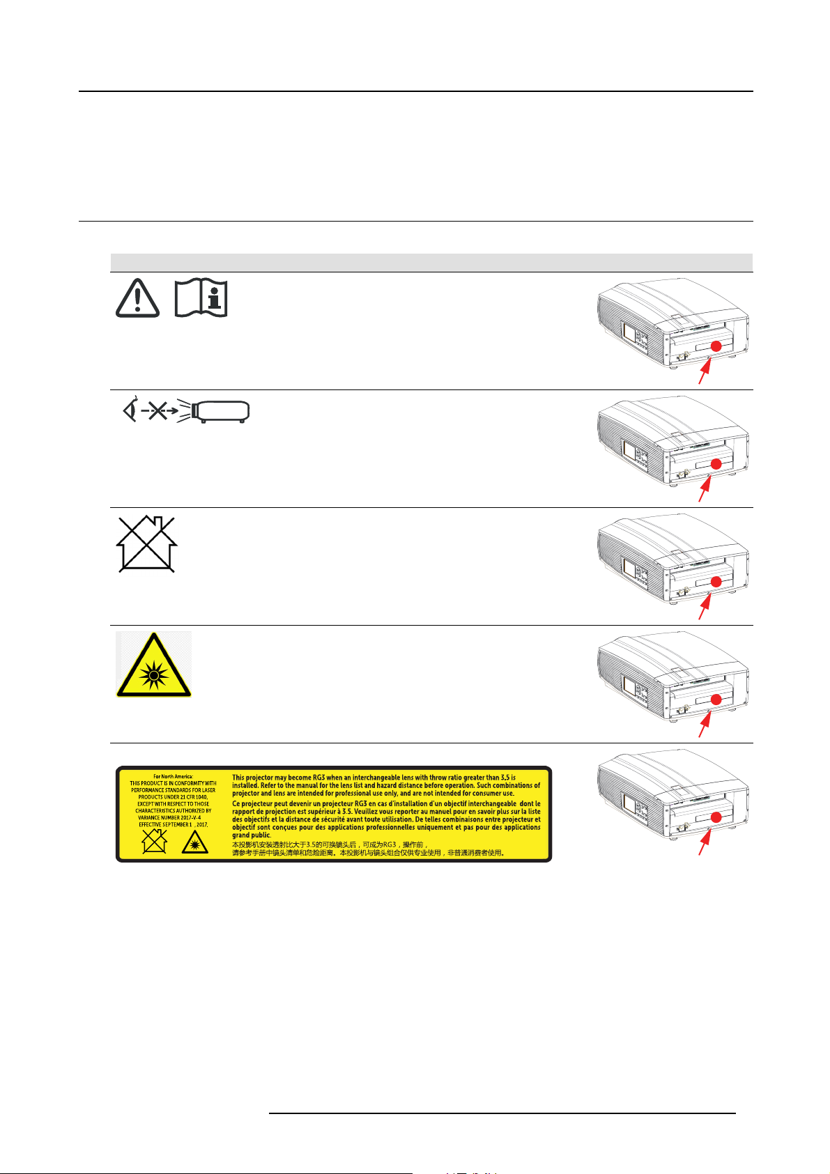
1.3 Product safety labels
Light beam related safety labels
Label image Label d escription Label location
Refer to user manual for further information!
Caution! Do not stare into beam, RG 2 product.
1. Safety
Hazard RG3: not for household use symbol.
Hazard RG3: optical radiation warning symbol.
For F 80-Q7, F80-4K7:
837
For North America: THIS PRODUCT IS IN CO NFORMITY WITH PERFORMAN CE
STANDARDS FOR LASER PRODUCTS UND ER 21 CFR 1040, EX CEP T WITH RESP ECT
TO THOSE CHARACTERISTICS AUTHORIZED BY VARIANCE NUMB ER 2017-V-4837
EFFECTIVE September 13, 2017.
This projector may become RG3 when an interchangeable lens with throw ratio greater than
3.5 is installed. Refer to the manual for the lens list and hazard distance before operation.
Such combinations of p
intended for consumer use.
Ce projecteur peut devenir un projecteur RG3 en cas d’installation d’un objectif
interchangeable dont le rapp ort de projection est supérieur à 3.5. Veuillez vous reporter
au ma nuel pour en savoir plus sur la liste des objectifs et la distance de sécurité av ant
toute utilisation. De telles combinaisons entre projecteur et objectif sont conçues pour des
applications professionnelles uniquement et pas pour des applications g rand public.
rojector and lens are intended for professional use only, and are not
R5906852 F80 SERIES 21/09/2017 7
Page 12
1. Safety
837
3
Label image Label d escription Label location
本投影机安装透射比大于3.5的可换镜头后,可成为RG3,操作前, 请参考手册中镜头清单和
危险 距离。本投影机与镜头组合 仅供专业使用,非普通消费 者使用。
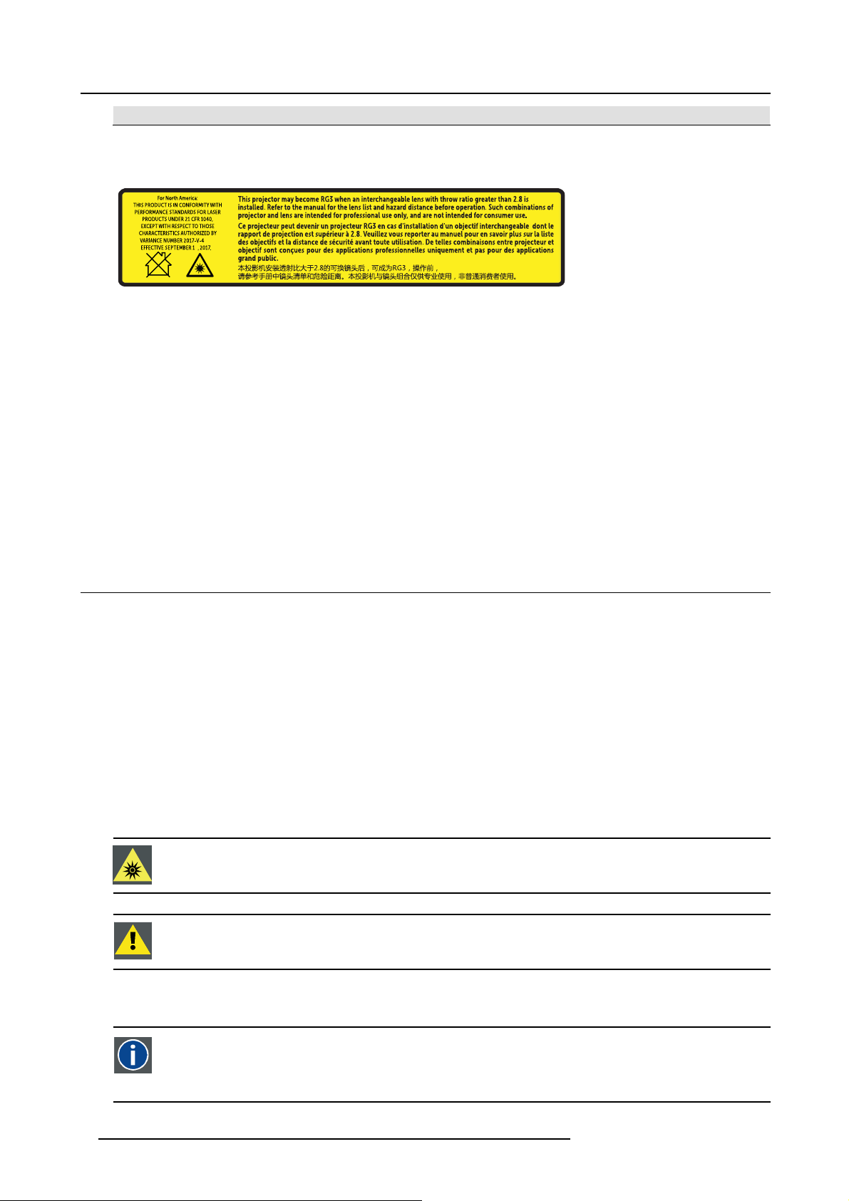
For F80-Ultra, F80-4K9, F80-Q9 :
837
For North America: THIS PRODUCT IS IN CO NFORMITY WITH PERFORMAN CE
STANDARDS FOR LASER PRODUCTS UND ER 21 CFR 1040, EX CEP T WITH RESP ECT
TO THOSE CHARACTERISTICS AUTHORIZED BY VARIANCE NUMB ER 2017-V-4837
EFFECTIVE September 13, 2017.
This projector may become RG3 when an interchangeable lens with throw ratio greater than
2.8 is installed. Refer to the manual for the lens list and hazard distance before operation.
Such combinations of projector and lens are intended for professional use only, and are not
intended for consumer use.
Ce projecteur peut devenir un projecteur RG3 en cas d’installation d’un objectif
interchangeable dont le rapp ort de projection est supérieur à 2.8. Veuillez vous reporter
au ma nuel pour en savoir plus sur la liste des objectifs et la distance de sécurité av ant
toute utilisation. De telles combinaisons entre projecteur et objectif sont conçues pour des
applications professionnelles uniquement et pas pour des applications g rand public.
本投影机安装透射比大于2.8的可换镜头后,可成为RG3,操作前, 请参考手册中镜头清单和
危险 距离。本投影机与镜头组合 仅供专业使用,非普通消费 者使用。
1.4 Risk Group 3 Safety
1.4.1 General considerations
Notice on optical radiation from F80 Projector when it becomes Risk Group 3.
• For RG3, no direct exposure to the beam shall be permitted.
For RG3, operators shall control access to the beam within the hazard distance or install the product at a height that will prevent
eye expo sure within the hazard distance.
• This projector has one or several built-in Class 4 laser clusters. Disassemb ly or modification is very dangerous and s hould
never be attempted.
• Any operation or adjustment not specific ally instructed by the user’s guide creates the risk o f hazardous laser radiation exp osure.
• Do not o pen or disassemble the projector as this may cause damage by the exposure of laser radiation.
FOR P ROFE SSIONA L USE ONLY means installation can only be carried out by Barco AUTHORIZED PERSONNEL familiar with
potential hazards associated with high intensity light beams.
WARNING: No direct ex posure to the beam within the h azard distance shall be permitted, RG3 (Risk Group
3) IEC 62471-5:2015
CAUTION: Use of controls or adjustments or performance o f procedures other than those specified herein
may result in hazardous radiation expo sure.
1.4.2 High Brightness precautions: Hazard Distance (HD)
HD
Hazard Distance (HD) is the distance measured from the projection lens at which the intensity or the energy per surface
unit becomes lower than the applicable exposure limit on the cornea or on the skin. The light beam is considered (to
be) unsafe for exposure if the distance from a person to the light source is less than the HD.
8 R5906852 F80 SERIES 21/09/2017
Page 13
1. Safety
Restriction Zone (RZ) based on the HD
The HD depends on the amount of lumens produced by the projector and the type of lens installed. See next chapter"HD in function
of the lens Throw Ratio (TR)", page 11.
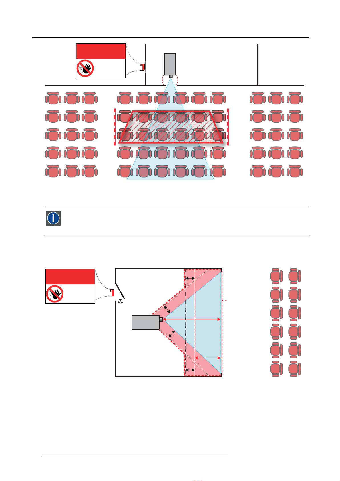
To protect untrained end users (as cinema visitors) the installation shall com ply with the following installation requirements: Operators shall control access to the b eam within the hazard distance or install the product at the height that w ill prevent spectators’ eyes
from being in the hazard distance. Radiation levels in excess of the limits will not be permitted at any point less than 2.0 meter (SH)
above any surface upon which persons other than operators, performers, or employees are permitted to stand or less than 1.0 meter
(SH) lateral separation from any place where such persons are permitted to be. In non-cinema environments where unrestrained
behavior is reasonably foreseeable, the m inimum separation height should be greater than or equal to 3.0 meter to pr event potential
exposure, for example by an individual sitting on another individual’s shoulders, within the HD.
These values are minimum values and are based on the guidance provided in IEC 62471-5:2015 section 6.6.5.
The end user must understand the risk and apply protective measures based upon the hazard distance as indicated on the label and
in the user information. Installation method, barriers, detection system or other applicable control measure shall prevent hazardous
eye access to the radiation within the hazard distance.
For example, projectors that have a HD greater than 1 m and emit light into an uncontrolled area where persons may be present
should be positioned in accordance with “the fixed projector installation” parameters, r esulting in a HD that does not extend into
the audience area unless the beam is at least 2.0 meter above the floor level. In non-cinema environments where unrestrained
behavior is reasonably foreseeable, the m inimum separation height should be greater than or equal to 3.0 meter to pr event potential
exposure, for example by an individual sitting on another individual’s shoulders, within the HD. For example, a sufficiently large
separation height may be achieved by mounting the image projector on the ceiling or through the use of physical barriers.
For applications installed in the USA market the above limits for cinema like environments do not apply. The relevant minimum
separation height is 2.5m (8,2 ft) by the FDA CDRH. Non cinema like environments require 2.5 meter (8.2 ft) separation height
and 1.0 meter (3.3 ft) separation width for areas where restrained behavior is to be expected. All other areas require 3.0 (9.9 ft)
separation h eight.
RA TH
HD
RA
SH
RZ
SH
Image 1-1
ASideview.
B Top view.
RA Restricted Access location (boot area of projector).
PR Projector.
TH Theater.
RZ Restriction Zone in the theater.
SH Separation Height.
SW Separation Width.
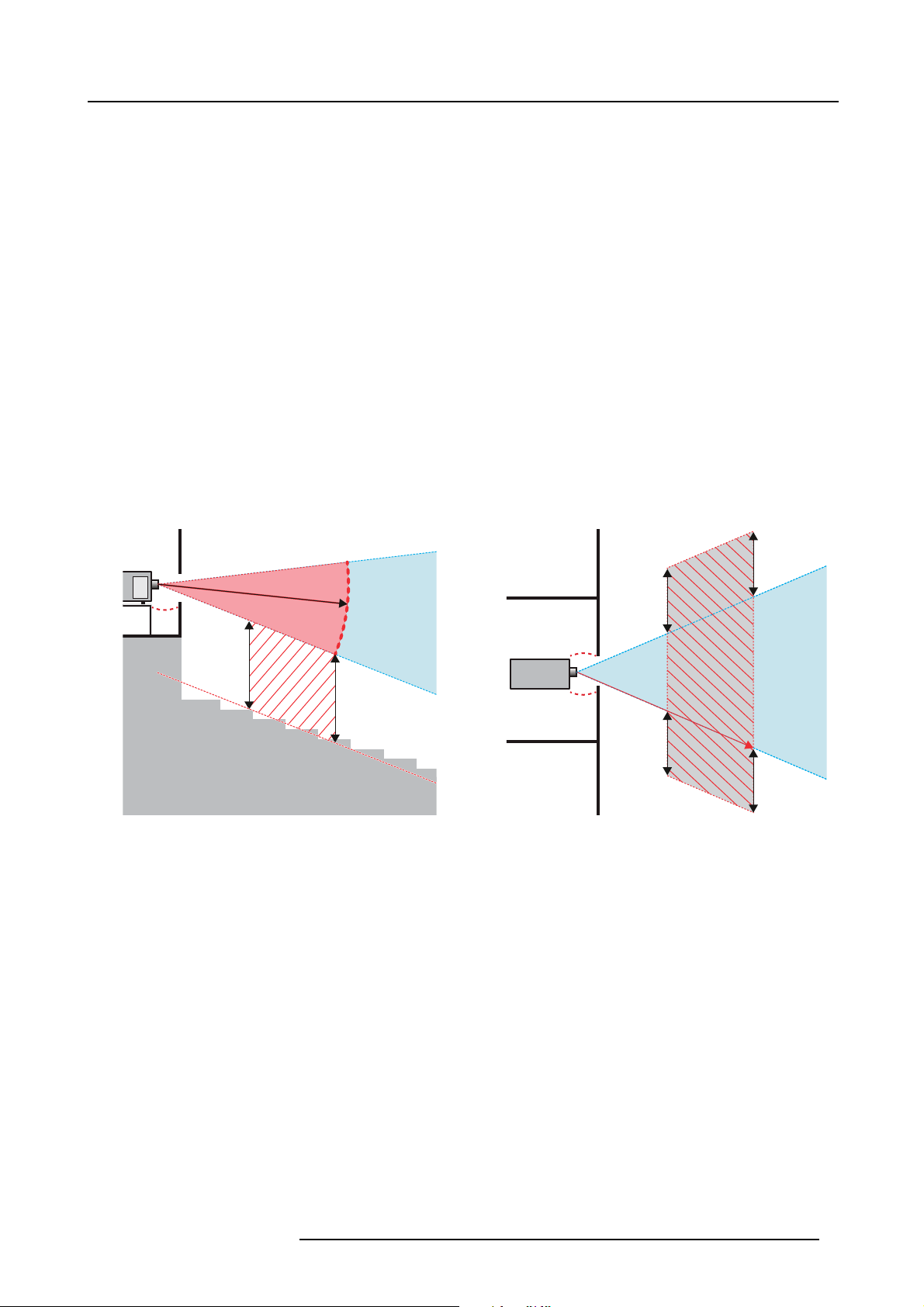
Based on national requirements, no person is allowed to enter the projected beam within the zone between the projection lens and
the related hazard distance (HD). T his shall be physically impossible by creating sufficient separation height or b y placing barriers.
The minimum separ
are permitted to stand.
Onimage 1-2 a typical setup is displayed. It mus t be verified if these m inimum requirements are m et. If r equired a restricted zone
(RZ) in the theater must be established. This can be done by using physical barrier, like a red rope as illustrated in image 1-2.
The restricted area sticker can be replaced by a sticker with only the symbol.
ation height takes into account the surface upon which persons other than operator, performers or employees
PR
(B) TOP VIEW(A) SIDE VIEW
TH
HD
SW
SW
SW
RZ
1m
SW
R5906852 F80 SERIES 21/09/2017
9
Page 14
1. Safety
Image 1-2
RESTRICTED
AREA
AREA
PR
RESTRICTED
1.4.3 HD for fully enclosed projection systems
HD
Hazard Distance (HD) is the distance measured from the projection lens at which the intensity or the energy per surface
unit becomes lower than the applicable exposure limit on the cornea or on the skin. The light beam is considered (to
be) unsafe for exposure if the distance from a person to the light source is less than the HD.
Restriction Zone (RZ) based on the HD
The projector is also suitable for rear projection applications; p rojecting a beam onto a defuse coated projection screen. As displayed
in image 1-3 two areas sho uld be considered: the restricted enclosed projection area (RA) and the observation area (TH).
RESTRICTED
RA TH
sw
AREA
RESTRICTED
AREA
HDDIFFUSE
RZ
sw
PR
sw
PD
HD
REFLECTION
sw
Image 1-3
RA Restricted Access location (enclosed projection area).
PR Projector.
TH Theater (observation area).
RZ Restriction Zone.
PD Projection Distance.
SW Separation Width. Must be minimum 1 meter.
For this type of setup 3 different HD shall be considered:
• HD as discuss ed in "High Brightness precautions: Hazard Distance (HD)", page 8 , relevant for intrabeam exposure.
•HD
•HD
10
: the distance that has to be kept restrictive related to the reflected light from the re ar projection screen.
reflection
: the relevant distance to be considered while observing the diffuse surface of the rear projection screen.
diffuse
R5906852 F80 SERIES 21/09/2017
Page 15
As des cribed in "High Brightness precautions: Hazard Distance (HD)", page 8 , it is mandatory to create a restricted zone within
the beam areas closer than any NO HD. In the enclosed projection area the combination of two restricted zones are relevant: The
restricted zone of the projected beam toward the screen; taking into account 1 meter Separation Width (S W ) from the beam onward.
Combined with the restricted zone related to the rear reflection from the screen (HD
separation.
The HD
projection screen. To determ ine the HD distance for the used lens and projector mod el s ee graphs in chapter "HD in function of the
distance equals 25% of the difference between the determined HD distance and the projection distance to the rear
reflection
); also taking into account a 1 meter lateral
reflection
lens Throw Ratio (TR)", page 11.
HD
reflection
= 25% (HD – PD)
The light emitted from the screen within the o bservation s hall never exceed the RG2 exposure limit, determined at 10 cm. The
HD
can be neglected if the measured light at the screen surface is below 5000 cd/m² o r 15000 LUX.
diffuse
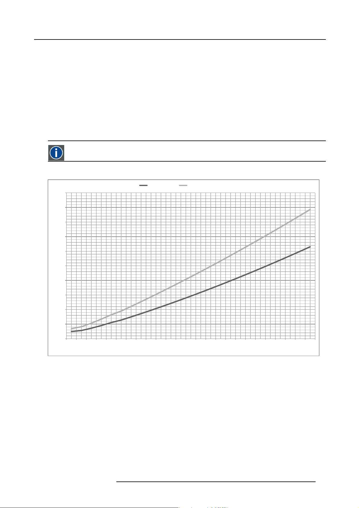
1.4.4 HD in function of the lens Throw Ratio (TR)
TR (Throw R atio)
The ratio of the distance to the screen (throw) to the screen width.
HD versus Throw Ratio
F80-Q7, F80-4K7 F80-Ultra, F80-Q9, F80-4K9
5
4.5
1. Safety
4
3.5
3
2.5
Hazard distance [m]
2
1.5
1
0.5
0
0.4 0.8 1.2 1.6 2.0 2.3 2.7 3.1 3.5 3.9 4.3 4.7 5.1 5.5 5.9 6.3 6.7 7.1 7.5 7.9 8.3 8.7 9.1 9.5 9.9
Image 1-4
Throw Rao
Graph shows Hazard Distance in meters versus Throw ratio of the lens
R5906852 F80 SERIES 21/09/2017
11
Page 16

1. Safety
12 R5906852 F80 SERIES 21/09/2017
Page 17
2. Remote Control Unit
2. REMOTE CONTROL UNIT
2.1 Remote control, Battery installation
Where to find the batteries for the remote control ?
The batteries are not placed in the remote control unit to avoid control operation in its package, r
time. At delivery the batteries can be found in a separated bag attached to the remote control unit. Before using your remote control,
install the batteries first.
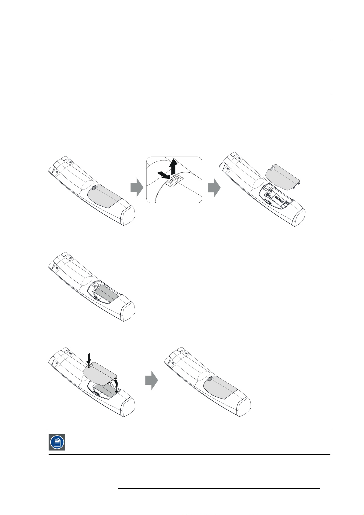
How to install
1. Push the battery cover tab with the fingernail a little backwards (1) and pull, at the same time, the cover upwards (2).
esulting in a s horter battery life
1
Image 2-1
2. Insert the two AA size batteries, making sure the polarities match the + and - marks inside the battery compartment.
Tip: Use alkaline batteries for optimum r ange and life t ime.
+
-
-
+
Image 2-2
3. Insert (1) both lower tabs of the battery cover in the gaps at the bottom of the remote control, and press (2) the cover until it clicks
in place.
2
2
+
-
Image 2-3
When replacing batteries, the broadcast address of the RCU will be reset to its default value ’0’.
R5906852 F80 SERIES 21/09/2017 13
1
-
+
Page 18
2. Remote Control Unit
CAUTION: Replace with the correct battery type. Use two AA size batteries. There is a risk of explosion if the
battery is replaced with an incorrect type.
CAUTION: Replace the battery as explained above. There is a risk of explosion if the battery is incorrectly
installed.
2.2 Using the XLR connector of the RCU
Connecting a cable with the X L R connector will reset the broadcast address of the RCU to its d efault value ’0’.
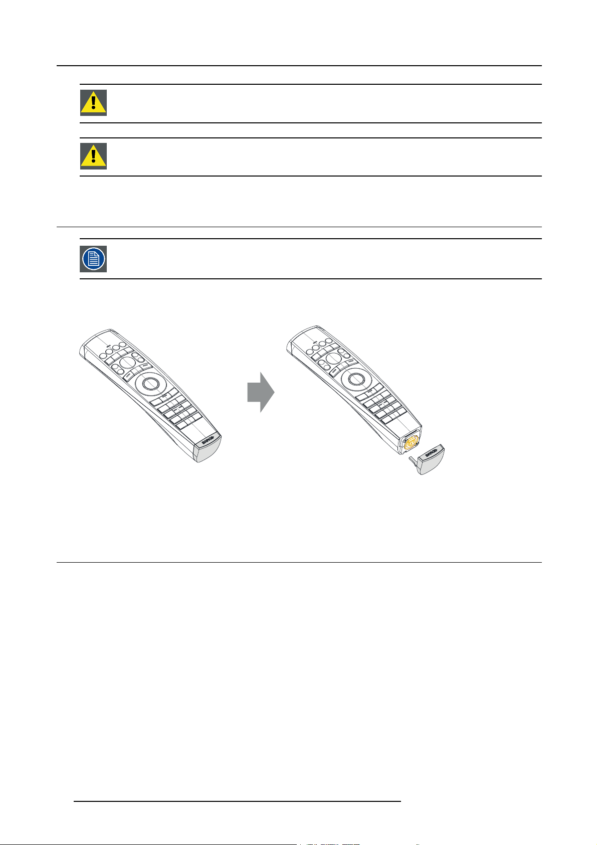
How to use the XLR connector
1. Remove the XLR cover by pulling it backwards.
Image 2-4
2. Connect a cable with XLR plug into the XLR connector of the R CU.
3. Connect the other end of the cable with the XLR inpu
t of the p rojector.
2.3 Remote control, on/off button
Purpose of the remote control on/off button
The Pulse remote control unit has at the front side an on/off switch (reference 1 image 2-5). Switching off the remote control prevents
that unwanted c omm ands are send due to an accidental key press. Furthermore, switching the RCU off will extend the battery life
time of the remote control.
To activate the re mote control press the on/off button.
To deactivate the remote control press the on/off button again.
Default when (re)placing batteries, is “ON”.
14
R5906852 F80 SERIES 21/09/2017
Page 19

Image 2-5
2. Remote Control Unit
1
R5906852 F80 SERIES 21/09/2017 15
Page 20

2. Remote Control Unit
16 R5906852 F80 SERIES 21/09/2017
Page 21
3. Input & Communication
3. INPUT & COMMUNICATION
Overview
• Introduction
• Connection Panel
• Making connections
• Connector specifications
• Control interfaces
• LED and Button indic ation chart
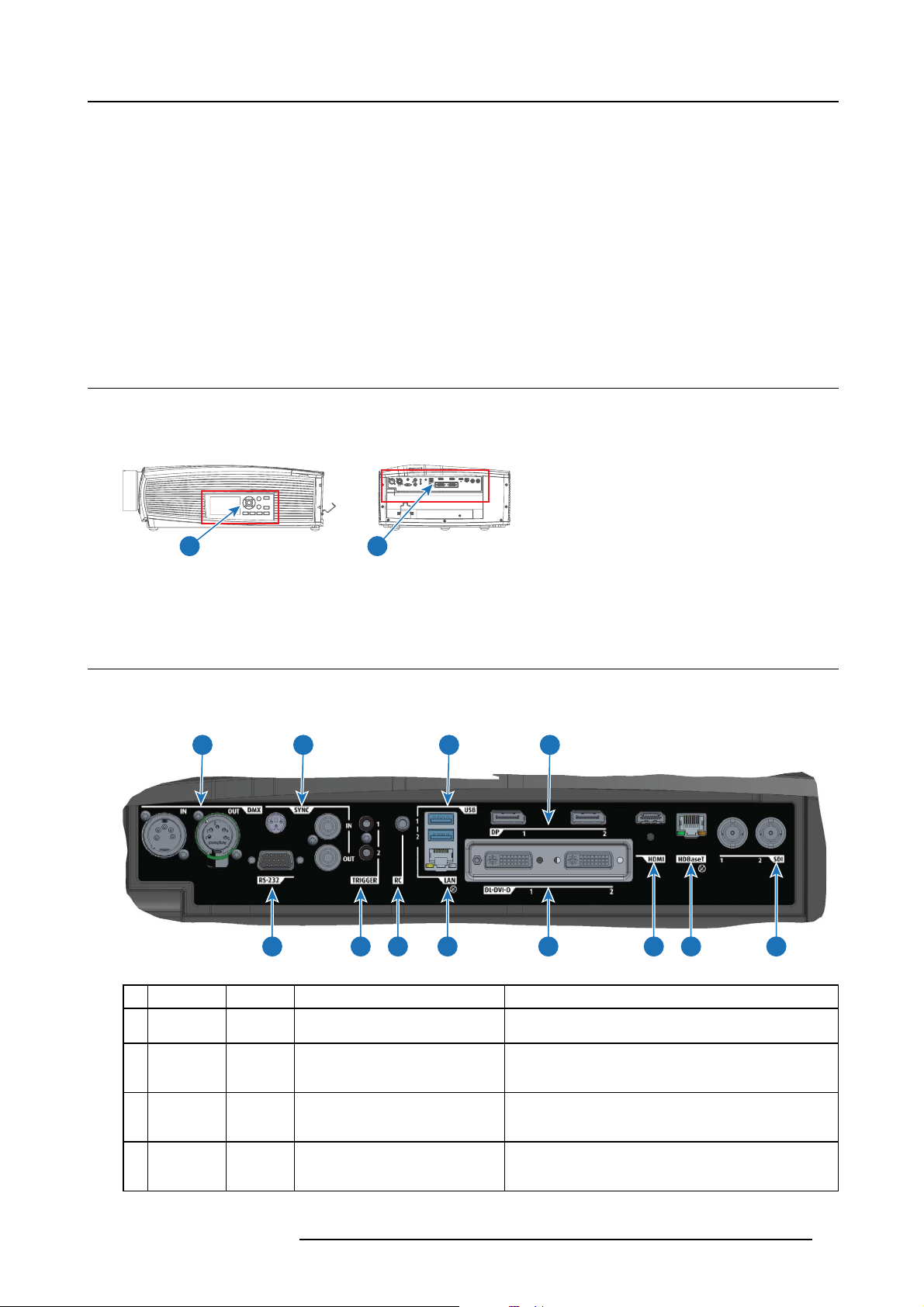
3.1 Introduction
General
The Input & Communication features of the pr ojector consists of a local keypad and a communication pane l situated at the left side,
and a connection panel (sources and control connections) located at the back side.
1 2
Image 3-1
1 local keypad and a communication panel
2 connection panel
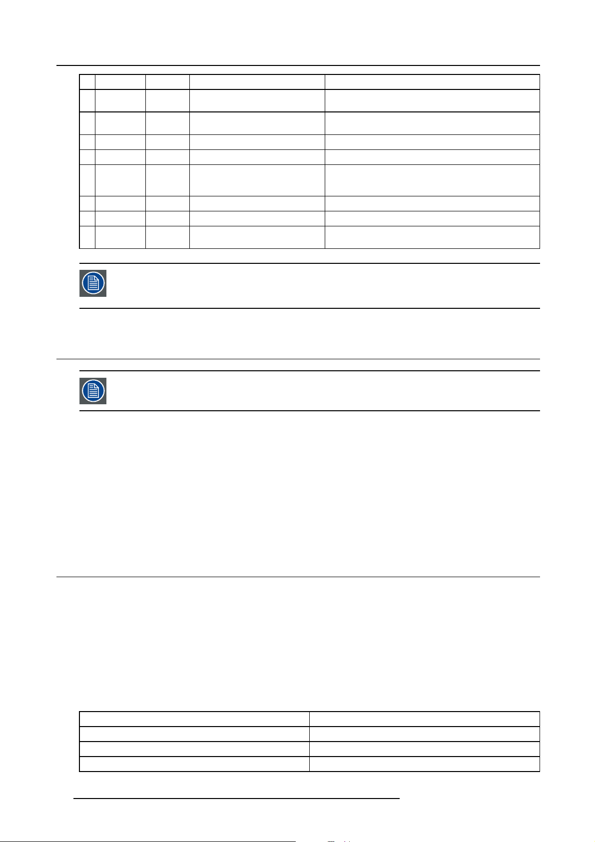
3.2 Connection Panel
General
Projector sources and control connections are located at the back of the projector.
1 3 6 8
2 4 5 7 9 1110 12
Image 3-2
Nb. Name Pcs Description Purpose
1DMX
IN/OUT
2
RS-232
3
Sync
4 Trigger 2 12VDC - 0,5A (6W) For C o ntrolling Peripherals, like motorized s creens,
2
1 9–pin DB9 connector
3
DMX 512 input / DMX 512 output For Projector Control
BNC Sync Port IN/OUT; Bidirectional
mini-DIN (1x 3D sync Out, and 2x
Sync In/Out)
For Projector Control. Allows for wired remote control and
monitoring of many projector functions used in installation
environments
For P roject or Control. This is mainly used in multiple
projector installations with requirement of synchronization
between the units
curtains etc. Give 12V output when projector are s witched
onSee also the note below.
R5906852 F80 SERIES 21/09/2017 17
Page 22
3. Input & Communication
Nb. Name Pcs Description Purpose
5
RC
6
USB
7
LAN 1
8DP 2
9DL-DVI-D 2
10 HDMI 1
11 HD Bas eT 1
12
SDI
1
2
2
Regarding the Trigger Output: If these o utputs are loaded too heavy, there is a risk that the projector will go
in reset mode, and restart. This causes no damag e to the projector, but is an undesirable response. This
will also happen if the startup current for the external equipment is too high, even though the nominal p ow er
consumption is less than 0,5A.
Mini jack 3,5mm connector for wired
remote
USB 2.0 type A, 4 pin( 2x Rear and
1x Front)
Standard RJ45 connector For Projector Control
Standard display port
Dual DVI-I 1.0 (DVI_D
Functionallity).
Standard HDMI 2.0
Standard RJ45 8P8C Connector For Projector Control
SDI1 is Input, SDI 2 is pass through.
(out)
For Projector Control
For Software upgrade
For Projector Input
For Projector Input. These connectors can als o be used to
form one uniform image by feeding half of the image into
each connector. HDCP compliant for sources up 165 Mhz
For Projector Input
For Projector Input
3.3 Making connections
The source switching time va ries from 0.5 to 5 seconds.
Source signal connectivity
The connector panel at the back of the projector is used for all source conne ctions.
Source signal connectivity on the projector is:
• 2x Dual Link DVI-I (DVI-D functionality)
• 2x DisplayPort 1.2
• 1x HDMI 2.0
• 1x HDBaseT
•1x3GSDI
3.4 Connector specifications
Overview
•DVI-I
• Display Port 1.2
• HDMI 2.0
•3G-SDI
• HDBase T
3.4.1 DVI-I
Specifications
Parameter Value
Connector DVI-I female digital RG B
Signal characteristics DVI 1.0, Digital, TMDS
Max. cable length
18 R5906852 F80 SERIES 21/09/2017
25 m (24 AWG)
Page 23
Parameter Value
Max. pixel rate
Scan format
Max. input data resolution
Bit depth 8 bit
EDID
HDCP Supported
330 MHz (dual link), 165 Mhz (single link)
Progressive
1920x1200 60Hz (Single link), 2560x1600 60Hz (Dual
Link).1920x2400 @60Hz
Supported
3.4.2 Display Port 1.2
Specifications
Parameter Value
Connector Standard Display port
Signal characteristics DP 1.2
Functionality Mandatory
Max. cable length 15 m (24 AWG) - RBR;
2m(24AWG)–HBR1,HBR2
Supported Link Rate
Scan format
Max. input data resolution
Bit depth 8, 10, 12 bit
EDID
HDCP Supported
RBR, HBR1, HBR2
Progressive
4096x2160 @60Hz (4K ) M ax
Supported
3. Input & Communication
3.4.3 HDMI 2.0
Specifications
Regarding HDMI 2.0: The decryption protocol HDCP 2.2 are enabled and valid in this unit.
Parameter Value
Connector Standard HDMI
Signal characteristics Digital, TMDS
Max. cable length 15 m (24 AWG)
Max. pixel rate 594MHz
Max. input data resolution 3840x2160 @6 0Hz
Bit depth 8, 10, 12 bits
EDID Supported
HDCP Supported
Ethernet No
Audio r eturn No
3.4.4 3G-SDI
Specifications
Parameter Value
Standard SMPTE 424M-2006 10bit level A
R5906852 F80 SERIES 21/09/2017 19
Page 24
3. Input & Communication
Parameter Value
Connectors 1x) BNC 75 ohm type IEC 60169-8, Am endme nt 2 1997, A
Bandwidth
Return loss
Impedance 75 ohm resistive
>3 G Hz
>10dB at 3GHz
3.4.5 HDBase T
Specifications
Parameter Value
Reference specification HDBaseT 1.0 Specification, June 2010
Connector Standard RJ-45, 8P8C
Signal characteristics HDBaseT
Max. cable length (1080p/48b/60Hz) 100 m (Cat5e/6), Pixel Clock <=225HHz, Video Datarate
Max TM DS Clock Frequency
Max video resolution supported
HDCP P ass-Through Yes, from S ource to Projector
IR Extension
RS-232 E xtension Not Supported
10/100Mbps Ethernet Pass-Through Not Supported
Fallback to 100BaseTx, IEEE 802.3u
USB O ver Centre Tap Not Su pported
Power Over Ethernet Not Supported
Audio
LEDs - HD Base Status Operation: Green, Left
<=5.3Gbps
70 m (Cat5e/6), Pixel Clock >225HHz, Video Datarate
>5.3Gbps
100 m (Cat6a/7), Pixel Clock >225HHz, Video Datarate
>5.3Gbps
270 MHz
1920x1200 @60Hz (WUXGA 60Hz)
Not Supported
Not Supported
Not Supported
Link/Mode: Yellow, Right
3.5 Control interfaces
About
The following control interfaces are available on the projector:
• 1x RS -232 (for projector control)
• 1x LA N/Ethernet (for projector control
• 3x USB-A ports
Overview
• RS-232
• LAN/Ethernet
• USB-A port
3.5.1 RS-232
Specifications
Parameter Value
RS-232 connector 1 female DB9 connector (RS232-in) for projector control and
20 R5906852 F80 SERIES 21/09/2017
debug
Page 25
3. Input & Communication
3.5.2 LAN/Ethernet
Specifications
Parameter Value
Ethernet connector 1 RJ45 Connec tor for projector control (not content)
Protocols DHCP, TCP/IP, UDP/P
Speed 10/100 Mbit/1000Mbit
3.5.3 USB-A port
Specifications
Parameter Value
USB connector Type A
Function Firmware upgrade using USB sticks
Power Power 5V, max 1,5A ( out)
Standard USB 2.0
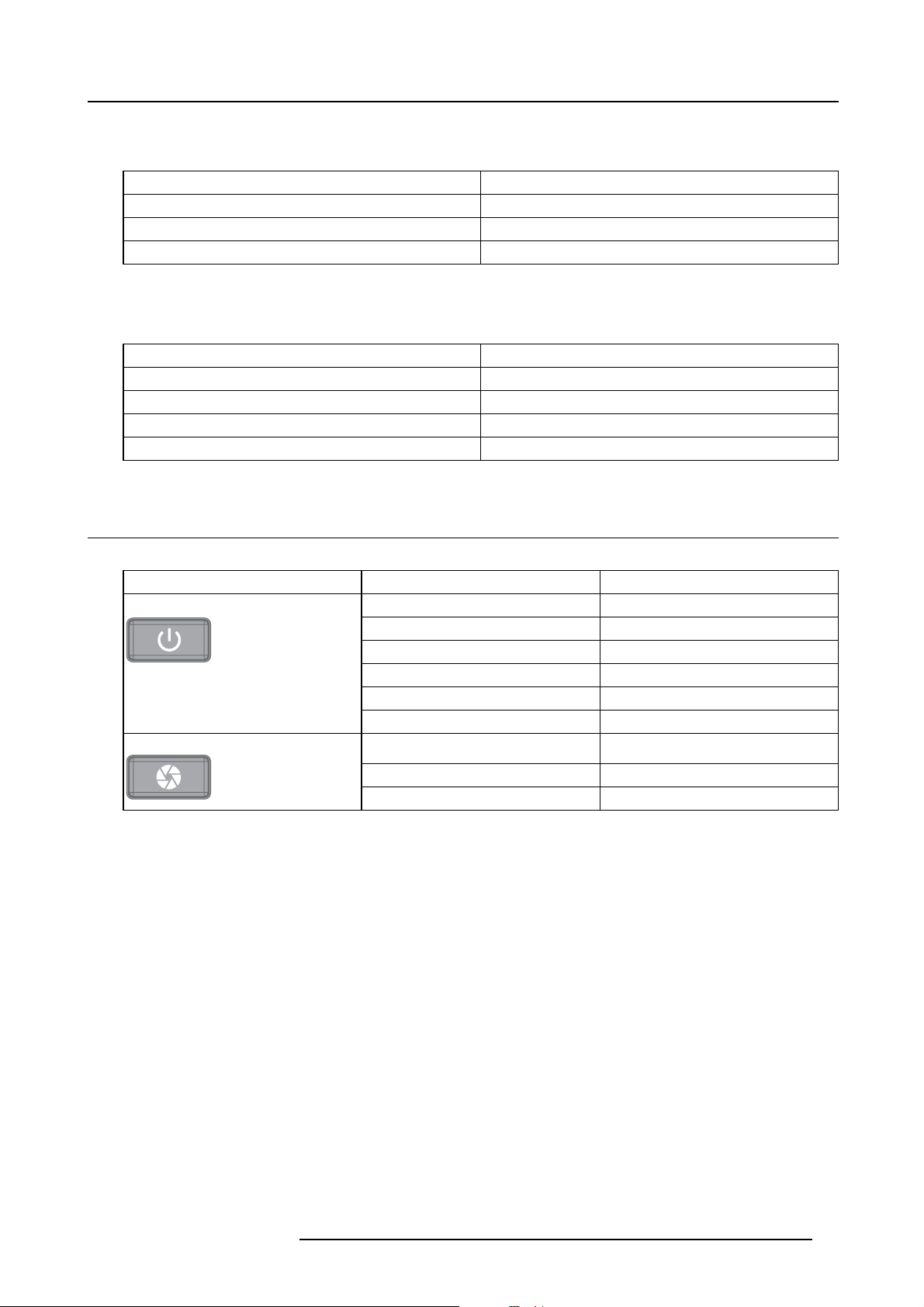
3.6 LED and Button indication chart
Button Backlight Status
Button
Standby button
Shutter button
Color status
Blinking WHITE (slow) Projector starts up (booting)
Blinking WHITE (fast)
Solid WH ITE Projector is in Standby mode
Blinking B LUE
Solid BLUE Projector is ON
Blinking RED Error condition
Off (no color) Projector is OFF, starts up, or is in Standby
Solid WH ITE Projector is ON, shutter is open
Solid RED Projector is ON, shutter is closed
Description
Firmware upgrade
Projector goes to ON mode
mode.
LED Status
The LED status is located on t he top side of t
During normal operation the LED is unlit. In the event of a critical error or high tem perature, the LED will display red.
By critical error, the projector c annot be restarted until the projector is disconnected from the power supply and then reconnected
again. If the reason for the error persist, the projector will again go to critical error status.
By high temperature, the projector will restart when it has coo led down, and temperatures are back within the normal operating
limitations.
he projector, near the IR receiver.
R5906852 F80 SERIES 21/09/2017
21
Page 26

3. Input & Communication
22 R5906852 F80 SERIES 21/09/2017
Page 27

4. Getting Started
4. GETTING STARTED
About this chapter
This chapter describes how to power up, control and set up your projector setup wh en the physical installation process is complete.
How controlling the projector ?
The projector can be c ontrolled by the local keypad, by the remote control unit or by browser application.
Location of the local keypad ?
The local keypad is located on the r ight side of the projector.
Remote control functions.
This remote control includes a battery powered infrared (IR) transmitter that allows the user to c ontrol the projector remotely. This
remote control is used for source selection, control, adaptation and set up.
Other functions of the remote control are :
• switching between stand by and operational mode.
• switching to "pause" (blanked picture, full power for immediate restarting)
• direct access to all connected sources.
Overview
• Functionality overview
• Power modes
• Power mode transitions
• Status o verview
• Power off projector
• Operation in 24/7 Mode
• Using the RCU
• Projector Address
• Quick setup via Direct acce ss
4.1 Functionality overview
Local Keypad overview
1
Menu Selection.
2
Menu Activation, OK button
3
OSD On/Off.
4
Menu Bac k.
5
Power On/Off.
6
To uch Panel O n/Off.
7
Input Selection.
8
Shutter Open/Close.
9
Te st Patterns.
10
Lens Menu.
11
To uch Panel.
The Keypad gives direct access to several functions, in addition to access to the m enu system.
The keypad has a back light that can be switched on a
nd off manually. The light turns off automatically after a preselected time.
1 2 3 4 5 6
1011 9 8 7
R5906852 F80 SERIES 21/09/2017
23
Page 28

4. Getting Started
The keys are equipped with white and blue backlit LEDs. Power button is equipped with white, blue and red bac klit. The LEDs are
controlled according to the features a vailable.
Remote Control Unit buttons
Backspace (while entering
14
values)
XLR connector.
15
Decimal mark (while entering
16
values)
Macro button.
17
Menu Bac k.
18
Default button.
19
Lens Focus.
20
Color On/Off.
21
Te st Patterns.
22
Power On.
23
10
11
12
13
1
2
3
4
5
6
7
8
9
24
23
22
21
20
19
18
17
1
Button pressed indicator.
2
Shutter Open.
3
Shutter Close.
4
Tou ch Panel O n/Off.
5
OSD On/Off.
6
Lens Zoom.
7
Lens Shift.
8
Menu Activation.
9
Menu Selection, O K button.
10
Menu Navigation.
11
Input Selection.
14
15
The projector remote control is a full feature wireless remote control, powered by two (2) standard AA batteries. The battery compartment is on the back s ide of the remote control.
The remote control is backlit for use in dark environments. It also has an XLR c onnector for wired connection to the projector. W hen
the wire is connected, the IR beam i
16
2625
s switched off.
12
Address button.
Numeric buttons.
13
Power Off.
24
Stereo Jack.
25
RCU On/Off.
26
LCD panel
The LCD panel has two main functions:
1. Showing the menus and adjustment information. and also a mirror of the OSD, (On Screen Display) described in User Interface
when this is enabled.
2. Information regarding the status of the projector showing this data:
- Projector status
- Network address
- Active source
- Current firmware version
- Operation Data
- Active functions (Enabled Functions).
Toggle between the two indications by using the Menu button on the keypad, or on the remote control
The LCD Display will fade out 30 seconds after the last key operation.
4.2 Power modes
General
The table below details the F80 po wer modes.
24
R5906852 F80 SERIES 21/09/2017
Page 29

4. Getting Started
Mode Description
ON (normal)
READY
ECO (Standby) Light source is switched off and projector electronics are
Energy consumption is significantly lowers in ECO (Standby) mode: only <0.5W if network is not plugged in
and 2W with network (WakeOnLan).
In ECO (Stand by) mode, remote power up ( Wake-on-LAN) an d local power up (button) are supported.
Projector is b ooted up and the light source is on
Projector is booted up but the light source is off
powered down
4.3 Power mode transitions
4.3.1 General
Transition Diagram
This diagram shows all modes available on the projector (un plug, ON, READY, ECO), and the actions ne cessary to change mode.
Image 4-1
-
Projector mains powered
-
-
Auto transition after x minutes if ECO mode enables
Press power On/Off button, remote On/Off button
ECO
READY
ON
1%
50%
2
50%
4.3.2 Power on projector
If not already connected,
tor. For m ore details see section dedicated to the po wer cord installation.
R5906852 F80 SERIES 21/09/2017 25
connect the female side of the power cord with the power input socket of the projec-
Page 30

4. Getting Started
The background image of the st artup screen and info screens can be changed with Projector Toolset with an
installed F80 plug-in.
Description
Plug the 3-prong plug of power cord into a grounded AC outlet. The projector will go to RE ADY m ode. During this stage the system
boots and performs the internal check of the boards. The Power On/Off button will BLINKING WHITE until READY mode is achieved.
Once in READY mode, the Power O n/O ff button will be lit WHITE.
4.3.3 Going from READY to ON
Description
Press the Power On/Off button on the projector, or the Power On button on the remote control. The projector will power ON.The
Power On/Off button will BLINK BLUE during the transition from READY to ON. Onc e the projector is o
will be lit BLUE.
n, the Power On/Off button
4.3.4 Going from ON to READY
Description
Press the Power on/off button on the projector, or the Power On button on the remote control. The projector will power down through
a cool down phase. The Power on/off button will BLINK WHITE during the transition from ON to READY. Once the projector is in
READY,thePower on/off button will be lit WHITE .
4.3.5 Going from READY to ECO standby
Description
If ECO Standby mode is enabled in the service menu (refer to the sect
projector will automatically go to ECO standby mode after a time-out (default 15 minutes). All electronics (including fans, pumps,...)
go down except for a very small w ake up controller. The Power on/off button will FLASH WHITE eve ry second.
ion "GUI - system settings/Standby ECO", in User Guide) the
4.3.6 Going from ECO to ON
Description
Press the Power on/off button on the projector, or the Power O n button on the remote control or do a wak e on LAN. The projector
goes from ECO directly to ON. The pr ojector will go through the same booting phase as on power plugging, then do the t ransition
from READY to ON. Of course startup-time will be longer then from READY to ON.
4.4 Status overview
Description
Once the projector is started, press Status to get an overview of parameters such as :
• Chosen source
• Current resolution and refresh rate
• Device s erial number and article num ber
• Current firm ware version and model name
• Current illumination (in percentage)
• Lamp runtime in hours
• Chosen comm unication method and IP address (if connected)
•Warpstatus
• Environmental temper ature
26
R5906852 F80 SERIES 21/09/2017
Page 31

4. Getting Started
Image 4-2
4.5 Power off projector
How to Switch off the projector
1. Use the standby button,orthePower On button on the remote control, to switch off the p rojector.
The projector will switch to READY mode first in order to run t h ro
25).
2. If ECO Standby mode is enabled in the service menu (refer to the section "GUI - system settings/Standby ECO", in User Guide)
the projector will automatically go to ECO standby mode after a time-out (default 15 minutes).
ugh a cool down phase (see "Power mode transitions", page
Some actions like apply a grey test pattern are done during the two minutes of the cool down phase in order
to minimize the potential effect of burn-in and increase the projector lifetime.
CAUTION: Never switch off the projector by mean
Barco advises to keep the projector always powered and use the ECO mode for low power consum ption.
s of unplugging mains cord or by cut down of mains power.
How to unplug the projector
1. Follow the procedure above to Switch Off the projector.
2. Wait at least 2 minutes prior to unplug the projector by removing the power cord from the AC outlet.
CAUTION: It is very important to wait few minutes before unplug the power cord. If the cool down phase is
not adhered, projector lifetime could be degraded.
4.6 Operation in 24/7 Mode
General
When the projector is destined to be operated continuously 24 hours a day / 7 days a week, some rules must be followed to minimize
the potential effect of burn-in and increase the projector lifetime.
R5906852 F80 SERIES 21/09/2017
27
Page 32

4. Getting Started
Important rules
If using the projector 24 h/day, please adher e to the following rules:
• Make sure to temporary switch off the projector during 2 minutes at least once per 12 hours. The power down a ction will
automatically and invisibly trigger a grey test pattern running within the projector. Alternatively, if you do not want to shut down
the projector, you can choose to select the grey test pattern yourself within the normal “on” mode.
• Apply moving video c ontent as much as possible, with on average a level of 50% white (long-term use of extreme black or white
content could potentially cause burn in).
4.7 Using the RCU
Pointing to the reflective screen
1. Point the front of the RCU to the reflective screen surface.
Image 4-3
IR control via reflective screen
Hardwired to the mini jack input
1. Plug one end of the remote cable in the connector on the front s ide (3,5mm mini jack) of the RCU.
2. Plug the other end in the c onnector on the communication interface of the projector, labelled Remote CTRL(reference 1, im-
age 4-4).
1
Image 4-4
Note: Plugging the rem ote control will switch the broadcast address of the remote control to the default value ’0’. This is the
only broadcast address that will work when hardwired. If you want to change the broadcast address after disconnecting
the remote control, see "Projector Address", page 29.
Pointing directly to the IR sensor
When using the wireless remote control, make sure you are within the effective operating distance (30m, 100ft in a straight line). The
remote control unit will not function properly if strong light strikes the sensor window or if there are obstacles between the remote
control unit and the projector IR sensor.
28
R5906852 F80 SERIES 21/09/2017
Page 33

45°
45°
F3
F
2
F
4
F1
F5
A
D
J
E
X
I
T
EN
T
E
R
P
A
US
E
TE
X
T
P
H
AS
E
90
SH
AR
P
N
7
8
TI
N
T
6
5
CO
LO
R
34
B
R
I
G
HT
N
2
1
CO
NT
R
TR
EB
LE
B
A
L
A
NC
E
BA
S
S
V
O
L
Image 4-5
RCU to one of the IR sensors
4. Getting Started
4.8 Projector Address
Projector address
Address installed in the projector to be individually controlled.
Broadcast address
Projector will always execute the command coming from a RCU programmed with that broadcast address.
4.8.1 Controlling the projector
Why a projector address?
As more than one projector can be installed in a room, each projector should be separately addressable with an RCU or computer.
Therefore each projector has its own address.
Set up an individual Projector Address
The set up of a projector address can be done via the software.
Projector controlling
Every projector requires an individual address between 0 and 255.
When the address is set, the projector can be controlled now:
• with the RCU: only for addresses between 0 and 31.
• with a computer: for any address between 0 a nd 255.
Broadcast Address
Every projector has a broadcast (com m on) address ’0’ or ’1’. The default address is ’0’.
The choice b etween ’0’ and ’1’ can be selected in the GUI: “System Settings” → “C omm unication” →“IR C ontrol “.
Placing new batteries in the remote control or plugging t he remote to a projector via a cable will automatically
reset the address back to its default value ’0’.
R5906852 F80 SERIES 21/09/2017 29
Page 34

4. Getting Started
4.8.2 Displaying and Programming addresses into the RCU
Displaying the Projector Address on the Screen.
1. Press the Address button to see the projector address (proximately 2 seconds ).
The projector’s address is displayed on the LCD status screen.
How to Program an Address into the RCU?
1. Press the Address button until the Button pressed indicator lights up continuously (proximately 5 seconds).
2. Enter the address with the digit buttons within the time the indicator lights up (also proximately 5 seconds).
Note: That address can be any value between 0 and 31.
Tip: A few examples:
To enter address 3, press "3" digit button on the RCU to set the RCU’s address to 3 and wait until the button pressed
indicator is out. Alternatively, you can also press “0” and “3”. This way, he button pressed indicator goes out immediately.
To enter address 31, then press “3” and “1” on the digit button on the RCU and the button pressed indicator g oes out
immediately.
4.9 Quick setup via Direct access
Quick source selection
1. Press the Input button on the rem ote control or local keypad.
Image 4-6
The source s election menu opens.
Image 4-7
Input selection
2. Use the arrow keys to selec t the desired s ource.
I
I
30
R5906852 F80 SERIES 21/09/2017
Page 35

Quick test pattern selection
1. Press the Test pattern button on the remote control or local keypad.
P
Image 4-8
A first test pa ttern will be displayed.
2. Press as may times on that button until the desired pattern is
displayed
4. Getting Started
P
R5906852 F80 SERIES 21/09/2017
31
Page 36

4. Getting Started
32 R5906852 F80 SERIES 21/09/2017
Page 37

5. Graphic User Interface (GUI)
5. GRAPHIC USER INTERFACE (GUI)
Overview
•Overview
• Navigation
• Tes t Patterns
5.1 Overview
GUI - Main Menu overview
The projector on screen display (OSD) is the primary user interface (UI). From here, you can review and adjust all projector and
display settings.
The OSD interface uses tabs to display the main menu. Each main menu contains submenus.
The OSD can be disabled by pressing the OSD on/off button.
Image 5-1
Home menu
The projector’s software platform uses access levels what each user can do. A standard user has access to all projector functionality.
Acertified service technician has also access to the service menu. This menu is password protected.
5.2 Navigation
Navigation via the RCU or local keypad
Navigating the OSD can be done using the remote control or the local keypad.
1 4
2 3
3 2 1
4
Image 5-2
R5906852 F80 SERIES 21/09/2017 33
Page 38

5. Graphic User Interface (GUI)
To start up the m enu structure, press MENU (1).
Use the arrow keys (Menu Navi ga tion buttons) to navigate to the desired menu item (2). The background color changes to light
blue.
Press the Men u Selection button (center key of the arrow keys), also called OK button, to activate that item and to jump one level
deeper (3).
Use the numeral keys to enter values, or use the arrow keys to move the bar scale up or down.
Press the Back button to go up one level (4).
Image 5-3
Home menu
Remark: a blue slider bar on the right side of the window means that there are more items to show than those currently displayed.
Define values
Menu settings are displayed using check boxes, bar scale sliders, a nd drop-down lists.
To set a value:
•PressOK to select or deselect a checkbox (turn a function O N or OFF).
• Use the arrow keys to move the bar scale slider up or down on the value line. For a bar scale 0-9, each step will equal 10% of
the total value.
• To enter the value as a direct number, press OK, input the digit(s), and then press OK again to execute and exit cursor mode
e.g. OK 79 OK .
Within an input field, use the * button as backspace button to remove an entered digit. Use the # button to enter a dot (.).
Changes to values are implemented dynamically.
To enter values with the local keyboard, use the arrow keys to select the first digit, press OK. Select the second digit and press OK.
Continue until all digits are entered. Close the action by selecting the enter (↵) button and press OK. Select the backspace button
and press OK to remove the last entered digit.
Menu memory
The OSD menu r emem bers the last selected s ub-item as long as the projector is running. The menu m e m ory is reset when res tarting
the projector from standby.
5.3 Test Patterns
How to use test patterns
1. In the main menu, select Test Patterns.
34
R5906852 F80 SERIES 21/09/2017
Page 39

5. Graphic User Interface (GUI)
Or,
Push the Test Patterns button on the RC or on the local keypad.
Image 5-4
Main menu, Test Patterns
2. In the Test Patterns menu, select either Patterns, Internal,orP7 Calibration test patterns.
3. In the chosen subm enu, select the desired test pattern from the list.
You can select one of the following Patterns test patterns:
-Refresh
- Native Blac k
You can select one of the following Internal test patterns:
- Aspect
- ANSI Lumen
- Ch ecke r Board
-Focus
- Cross hatch
- Mono scope
- FRHL
-Green
-FocusBW
- Color bars
-Blue
-Red
-White
You can select one of the following P 7 Calibration test patterns:
-NativeRed
- Native Green
- Native Blue
-NativeWhite
4. To turn the test pattern off, return to the previous menu.
R5906852 F80 SERIES 21/09/2017
35
Page 40

5. Graphic User Interface (GUI)
36 R5906852 F80 SERIES 21/09/2017
Page 41

6. GUI – SOURCE
About the Source menu
This menu is used to select, review an d configure sources into the projector.
Overview of features
• Source Selection
• Connector Settings
6.1 Source Selection
How to select?
1. Press Menu to activate the men us and select Source.
6. GUI – Source
Image 6-1
Select Source
2. Press OK.
The Select Source menu is displayed with the actual available sources filled out.
3. Select the desired input.
6.2 Connector Settings
How to configure the connector
1. Press Menu to activate the men us and select Source.
Image 6-2
Select Source
2. Press OK.
The Select Source menu is displayed with the actual available sources filled out.
3. Scroll down to the bottom of the list and select Connector Settings.
Image 6-3
The available sou rces are displayed.
4. Select the desired connector.
R5906852 F80 SERIES 21/09/2017
37
Page 42

6. GUI – Source
The Connector Settings menu for this conne ctor will be displayed. All default values ar e Auto.
Image 6-4
5. To apply a limit on the used co lor space, se lect one of the other values in Color space.
6. To apply a limit on the use d signal range, select one of the other ranges in Signal Range.
38
R5906852 F80 SERIES 21/09/2017
Page 43

7. GUI – IMAGE
Overview of features
• Setting image levels manually
• P7 Realcolor
• HDR – P erceptual Quantizer (PQ)
7.1 Setting image levels manually
Purpose
Contrast: Change the contrast of the complete output s ignal (main and P iP window together) of the projected image.
Brightness: Change the brightness of the complete output signal (main and PiP window together) of the projected image.
Saturation: Change the saturation of the complete output signal (main and P iP window together) of the projected image .
How to set up Contrast
1. In the main menu, select Image → Contrast.
7. GUI – Image
Image 7-1
Image menu — Contrast
2. Use the ◄ or ► key to c hange the contrast enhancement until the desired value is reached (adjustable between 0 and 2).
Image 7-2
Contrast slider
3. Use the ▲ or ▼ key to select Saturation or Brightness.
Or,
go to H ome - Image and select Saturation o
r Brightness.
How to set up Brightness Level
1. In the main menu, select Image → B rightness.
Image 7-3
Image menu — Brightness
2. Use the ◄ or ► key t o change the brightness until the desired value is reached (adjustable between –1 and 1).
R5906852 F80 SERIES 21/09/2017
39
Page 44

7. GUI – Image
Image 7-4
Brightness slider
3. Use the ▲ or ▼ key to select Contrast or Saturation.
Or,
go to Home - Image and select Contrast or Saturation.
How to set up Saturation Level
1. In the main menu, select Image → Saturation.
Image 7-5
Image menu — Saturation
2. Use the ◄ or ► key to change the saturation until the desired value is reached (adjustable between -1 and 1).
Image 7-6
Saturation slider
3. Use the ▲ or ▼ key to select Brightness or Contrast.
Or,
go to Home - Image and select Brightness or Co ntrast.
7.2 P7 Realcolor
Purpose
When blending images from multiple projectors, the measured color coor dination of each projector can be altered to a desired
common level. This so that the projected colors are identical over all projectors used.
How to set the P7 desired values
1. In the main menu, select Image → Advanced → P7 R ealcolor.
40
R5906852 F80 SERIES 21/09/2017
Page 45

7. GUI – Image
Image 7-7
Advanced menu — P7 Realcolor
The P7 menu is displayed.
Image 7-8
P7 Realcolor menu
2. Select the desired Mode. Choose one of the following:
- Native: Default mode, with default values . All other options in the P7 menu are disabled.
- Custom RGB: 3–point color configur ation. In RGB mode, the C, M and Y c
on the R, G and B coordinates.
- Custom RGBCMY: 6–p oint color configuration (both RGB and CMY). In RGB CM Y mode, each color can be given a specific
coordinate within the measured color triangle.
- Custom WHITE:Configure only the White temperature.
3. Define the coordinates for each available color.
Click on a coordinate value and s elect the current value. Enter the desired value with the numeric keys.
Note: You can only pick coordinates within the measured color triangle.
4. For Custom White, click on W hite point and choose one of the following:
- Coordinates:Configure the white point via specific coordinates. The white point is specified using an x, y coordinate in the
CIE 1931 Chart.
- Temperature:Configure the white point via a color temperature slider. The white point is specified on a Kelvin scale between
3200K and 13000K tracking along the black body curve.
oordinates will be calculated automatically based
You can reset all co ordinates to the de fault values (to native) by selecting Reset modes to native. Press OK
button to reset.
7.3 HDR – Perceptual Quantizer (PQ)
About PQ
Perceptual Quantizer (PQ) is a, electro-optical transfer function (EOTF) that allows for the display of High Dynamic Range (HDR)
content with a luminance level of up to 10 000 cd/m² and can be used with the Rec. 2020 color space.
If your provided HD R content has been mastered with Perceptual Quantzier (e.g. Dolby Vision or HDR10), you can adapt the
luminance on screen to adapt to the provided content.
For optimal display of HDR content, this is just one value that will influence the projected image. When entering the desired screen luminance, take into account the distance of the projector to the screen and the quality
of the scree n used.
How to set the PQ?
1. In the main menu, select Image → Advanced → PQ.
R5906852 F80 SERIES 21/09/2017
41
Page 46

7. GUI – Image
Image 7-9
The PQ menu is displayed
Image 7-10
2. Select the desired Unit (nits or foot-lambert).
3. Enter the Screen luminance (either in nit, or foot-lambert).
42
R5906852 F80 SERIES 21/09/2017
Page 47

8. GUI – INSTALLATION
Overview of features
•Configuring the lens, shift
• Orientation
• Warping
• Blending
• Laser illumination
• Active 3D Set up
8.1 Configuring the lens, shift
What can be done?
The image can be sh ifted by us ing the vertical and horizontal lens shift.
Lens shift is only possible when lens shift is calibrated. Please refer to the len s calibration section in System
Settings → Lens Cal ibration menu.
Vertical and Horizontal Shift
1. To change the position of the projected image, select Installation → Lens → Shift.
8. GUI – Installation
Image 8-1
Lens menu, Lens shift
2. Use the ▲ or ▼ key to shift the lens (image) in vertical direction.
Use the ◄ or ► k ey to shift the lens ( image) in horizontal direction.
Image 8-2
Shift adjustment
8.2 Orientation
What can be done?
The way of physical installation of the projector can be defi ned to the projector.
R5906852 F80 SERIES 21/09/2017
43
Page 48

8. GUI – Installation
The following installation are possible:
• front/table
• front/ceiling
• rear/table
• rear/ceiling
How to set the correct orientation
1. In the main menu, select Installation → Orientation.
Image 8-3
Installation menu, Orientation
The Orientation m enu is displayed.
Image 8-4
Orientation m enu
2. Use the ▲ or ▼ key to select the desired mounting position and press OK button to activate.
Use the ▲ or ▼ key to select the desired projection position and press OK button to activate.
8.3 Warping
8.3.1 About warping
Overview
Image warping is the process of digitally manipulating an image to compensate for the distortion of the screen. Consequently, it can
also be used to generate an image with irregular shape.
While an image can be transformed in various ways, pure warping do esn’t affect the colors.
8.3.2 Warping – On/Off
About warping on/off
By toggling between on and off the warping functionality can be enabled or disabled.
How to toggle
1. In the main menu, select Installa tion → W
arp.
44
R5906852 F80 SERIES 21/09/2017
Page 49

Image 8-5
2. In the Warp menu, click Warp to toggle between On and Off.
8. GUI – Installation
Image 8-6
Image 8-7
8.3.3 Warping – Screen Size
About (Warp) Screen Size adjustment
If the used source aspect ratio is different than the projector aspect ratio, e.g. source is 16:9 and projector is 16:10, then black bars
will be projected. In the example case a black bar on top and bottom of the image will be projected. The warp area contains not
only the image information but also the black bars. If we want to position e.g. the active left top corner exactly on the screen u sing
4 corner warp, then it is very hard to do that as we are moving the black left top corner and we do not have control over the exact
position of image left top corner. By moving the outline of the warp screen size to the active image information, the corner points of
the warp area are now exactly on the corner points of the active image information and makes w arping much easier.
Image 8-8
Warp outline examp le
How to adjust the image?
1. In the main menu, select Installation → Warp → Screen Size.
R5906852 F80 SERIES 21/09/2017
45
Page 50

8. GUI – Installation
Image 8-9
Warp M enu, Screen Size
The Screen Size menu is displayed.
Image 8-10
Screen size
2. Select either Screen width or Screen height.
3. Set the new value to shrink either the width or height of the warp outline so that the outline is equal with the active source.
Tip: A red border will be projected along with the current image. The bord er is a visual tool, showing the result of the adjusted
outline.
4. Click Apply.
8.3.4 Warping – 4 corners adjustment
About 4 Corners adjustment
4 corner adjustment is typically used when the mechanical installation of the projector p revents it from pointing perpendicularly at
the screen. For example, you can overshoot the screen and use 4 corner adjustm ent to pull your projected image corners back into
the sc reen.
Some examples:
Image 8-11
4 corner adjustment
How to adjust the image?
1. In the main menu, selec t Installation → Warp → 4 Corners.
46
R5906852 F80 SERIES 21/09/2017
Page 51

Image 8-12
Warp menu, 4 Corners
The 4 Corners menu is displayed.
8. GUI – Installation
Image 8-13
4 Corners Warping
2. To enable 4 Corners warping, make sure the 4 corners slider is set to On.
The slider is enabled whe n set to the right and when it is colored blue.
3. To set war ping on one or more of the four corners, select one of the four corners.
4. Set the desired X and Y coordinates for this corner, using the arrow keys.
Tip: A red border corner will be projected along with the current image
. The border is a visual aid, showing the result of the
warped corners.
5. Repeat from step 3 for each corner, until all corners are warped in the desired position.
To reset the 4 corner adjustments, select Reset and press the OK button.
8.3.5 Warping – Bow
About bow adjustment
A bow distortion can be adjusted so that a normal image is displayed. P ositive adjustments introduce m ore outside bow distortion.
Negative adjustments introduce m ore inside bow
distortion.
R5906852 F80 SERIES 21/09/2017
47
Page 52

8. GUI – Installation
Image 8-14
Bow distortion
How to adjust
1. In the main menu, select Installa tion → Warp.
Image 8-15
Installation menu, Warp
2. In the Warp menu, select Bow.
Image 8-16
Warp menu, Bow
A check symbol at the bottom right corner indicates that the bow function is activated.
3. To enable Bow correction, make sure the Bow slider is set to On.
The slider is enabled whe n set t
o the right and when it is colored blue.
48
R5906852 F80 SERIES 21/09/2017
Page 53

Image 8-17
Bow adjustment
4. To enable a symmetric adjustment, m ake sure the Symmetric slider is set to On.
The slider is enabled whe n set to the right and when it is colored blue.
5. Select an adjustment point and use the ar row keys to a djust.
When s electing a mid point of an edge, the bow angle can be ad justed.
When selecting a corner point, the linearity can be adjusted.
To reset the bow adjustments, select Reset and press t he OK button.
8. GUI – Installation
8.3.6 Warping – Warp files
About custom Warp Files
Next to setting your specific warp configuration in the G UI, you can also upload or download a custom warp grid in xml forma t to/from
the projector. This is a time-saving option whe n multiple projectors need an identical Warp configuration.
To upload or download warp files you can use Projector Toolset or upload/download the warp grid in the format of an xml file. Alternatively, you can contact the “file endpoint” directly via the curl program or some other tool that supports http upload.
For more information on uploading/downloading Warp files using the Projector Toolset, refer to the Projector Toolset user manual.
For more information on uploading/downloading Warp files using curl or other tools that supports HTTP upload, refer to the Pulse
API Reference Guide.
HowtoactivateanuploadedWarpgrid?
1. In the main menu, select Installa tion → Warp.
Image 8-18
Installation menu, Warp
2. In the Warp menu, select Files.
Image 8-19
Warp menu, Files
R5906852 F80 SERIES 21/09/2017 49
Page 54

8. GUI – Installation
The Warp Files menu is displayed.
Image 8-20
3. If any custom Warp files are available, select the desired warp file.
Image 8-21
4. Click on the on/off button o n top to activate the selected warp file.
Image 8-22
8.4 Blending
About Blending
Blending is used in multi channel ins tallation to have a seamless transition between the channels. Image blending gives the appearance of a single view, thus achieving re alistic immersion for the majority of wide screen applications.
The principle is that the light intensity in the blend zone from each projector will be adjusted individually, so t hat the rendering on the
screen are perceived as from one projector.
From the start (offset) position, you can blend zone size per edge (left, top, right, bottom ). For each edge there will be a drop-off
curve for the blend zone.
50
R5906852 F80 SERIES 21/09/2017
Page 55

8. GUI – Installation
8.4.1 Blend Zones
About offset and blending width or height
Offset is used to clip the image. T he larger the offset value, the more the image is masked (by black bar) at the co rresponding side.
E.g. Top offset of 100 will blank the top 100 lines.
Height or width is used to create a blending zone w ith a smooth brightness drop off. This is used to compens ate for the double
brightness in overlap areas. The value is the size of the blended area in pixels.
How to adjust blend zones?
1. In the main menu, select Installation → Blend → Blend Zones.
Image 8-23
Blend menu, Zones
The Blend zones m enu is displayed
Image 8-24
Blend Zone menu
2. To enable blending, put the switch to the right. The color of the switch b ecom es blue when activated.
3. To show blending lines on the screen, put the switch before Show lines to the right. The color of the switch becomes blue when
activa ted.
4. Specify the start position (offset)(1) for the blending height and width, setup an size value (2) to determine the width of the blending
area.
When the blending lines are activated, you will get a visual indication of the sc reen of the installed blending area.
R5906852 F80 SERIES 21/09/2017
51
Page 56

8. GUI – Installation
1
2
Image 8-25
1 Start position (offset)
2 Blending width
5. First select an offset and click Menu selection to activate the selection.
Use the arrow keys to change the value (the start position of the blending)
Repeat for the other edges if necessary.
6. Select the height or width and setup a size value.
Repeat for the other edges if necessary.
The value will range from 0 to 1.0 (linear to S- curved), with a default value of 0.5.
Example of the use of blending
When projecting an im age with 2 projectors, there is always an small overlap that s hould be corrected by using the blending function.
In order to obtain a satisfying result for the Bl
at least 10% of the picture width.
The basic principle is that the overlap setup in the source shall correspond with the blend width setup for the projector. That means
that if the overlap zone for the source is set to 500 pixels, the width of the blend zone for the projector also must be set to 500 pixels.
First step is to align the image from the projectors as accurate as possible in a mechanical way, meaning without any optical corrections. A t the s ame time, establish an overlap in the pictures between the two screens.
Then adjust the remaining irregularities by using the shift and war p features in the projectors to obtain the las t fi ne tuning of the
alignment.
Enable b lending and activate Show lines.
First set the blending width for the right edg
eofthefirst projector. Enter a width value equal to the overlap area (width1).
Repeat for the left edge of the second projector.
Adjust the offset to cut the image on each side (masking).
end function, the overlap / Blend z one are recom m en ded to be
52
R5906852 F80 SERIES 21/09/2017
Page 57

Image 8-26
Set up for projector 1
8. GUI – Installation
Image 8-27
Set up for projector 2
8.4.2 Black level adjustment
About adjusting the black level
The purpose of the black level adjustment i
regions.
This is needed because the black levels will be brighter in the blend zones, since multiple projectors will project on the same screen
area.
The size of the black level area is calculated automatically from the blend zones. This is done by using the start position and size of
each edge of the blend and adding an additional size of 8 pixels to reduce the effect know n as "sea of mirrors".
You can also specify the offsets manually by turning off the automatic calculation. The black level value is adjusted in a 8 bit resolution
from 0 t o 255.
s to align the black levels in the overlapped regions with the black levels in the other
How to adjust the black level manually
1. In the main menu, select Installa
tion → Blend.
R5906852 F80 SERIES 21/09/2017
53
Page 58

8. GUI – Installation
Image 8-28
Installation menu, Blend
2. In the Blend menu, select Black Level.
Image 8-29
Blend menu — Black level
The Black Level m enu is displayed.
Image 8-30
Black Level menu
3. To manually change the black levels, disable t he Automatic slider on top of the menu.
4. Slide the Offset sliders to the desired position. You can change the offset for top, bottom, left and right edge.
5. Slide the Intensity slider to the desired position.
8.4.3 Black Level Files
About custom Black Level Files
Next to setting your specific Black Level Adj
file in xml format to/from the projector.
To upload or download Black Level adjustment files you can use Projec tor Toolset or upload/download the Black Level adjustment
file in the format of an xml file. Alternatively, you can contact the “fi le endpoint” directly via the curl program or some other tool that
supports http upload.
For more information on uploading/downloading Black Level fi les using the Projector Toolset, refer to the Projector Toolset user
manual.
For more information on uploading/downloading Black Level fi les using curl or other tools that supports HTTP upload, refer to the
Pulse API Reference Guide.
ustment in the GUI, y ou can also upload or download a custom Black Level adjustment
How to activate an uploaded Black Level adjustment file?
1. In the main menu, select Installation → Blend.
54
R5906852 F80 SERIES 21/09/2017
Page 59

Image 8-31
Installation menu, Blend
2. In the Blend menu, select Black Level Files.
Image 8-32
Blend menu, Black Level F iles
The Black Level Files menu is displayed.
8. GUI – Installation
Image 8-33
3. If any custom Black Level adjustment files are available, select the desired file.
Image 8-34
4. Click on the on/off button on top to activate the selected Black Level adjustment file.
8.4.4 Blend Files
About custom Blend Files
Next to setting your specific Blending c onfigurationin the GUI, you can also upload or download a custom B lend configuration file in
xml format to/from the projector. T his is a time-saving option when multiple projectors need an identical blending configuration.
To upload or download Blend configuration files you can use Projector Toolset or upload/download the Blend co nfigura tion file in the
format of an xml file. Alternatively, you can contact the “file endpoint” directly v ia the curl program or some other tool that supports
http upload.
For more information on uploading/downloading Blend files using the P rojector Toolset, refer to the Pr ojector Toolset user manual.
R5906852 F80 SERIES 21/09/2017
55
Page 60

8. GUI – Installation
For more information on uploading/downloading B lend files using curl or other tools that supports HTTP upload, refer to the P ulse
API Reference Guide.
How to activate an uploaded Blend configuration file?
1. In the main menu, select Installation → Blend.
Image 8-35
Installation menu, Blend
2. In the Blend menu, select Blend Files.
Image 8-36
Blend menu, Blend Files
The Blend Files menu is displayed.
Image 8-37
3. If any custom Blend files are available, select the desired file.
Image 8-38
4. Click on the on/off button on top to activate the selected Blend file.
56
R5906852 F80 SERIES 21/09/2017
Page 61

8.5 Laser illumination
What can be done?
Within a cer tain power mode, the light output of the laser can be reduced by reducing the laser power.
How to reduce the power
1. In the main menu, select Installation → Illumination → Power.
Image 8-39
Illumination menu, Power
The actual power setting is indicated at the bottom of the Power button.
2. Use the Slider to change the power value.
8. GUI – Installation
Image 8-40
Laser power adjustment
8.6 Active 3D Set up
About active 3D
The projector supports active 3D, in combination with a 3D emitter and compatible battery–operated shutter glasses. The options
on the p ro jector allow you to fine-tune the 3D settings accordingly to the specifications of the 3D emitter.
If a 3D emitter is used that radiates IR beams, the IR beams may interfere with the IR communication b etween
projector and the RCU . I f such interference occurs, connect the RCU to the projector using the remote cable.
It is also advised to turn the IR receivers on the
the IR receivers, see "Remote control, on/off button", page 14.
How to adjust the projector to the 3 D emitter?
1. In the main menu, select Installation → 3D Set up.
Image 8-41
The 3D set up m enu is displayed
projector off to avoid the 3D em itter interference. To turn off
Image 8-42
R5906852 F80 SERIES 21/09/2017 57
Page 62

8. GUI – Installation
2. Select the desired the stereo D a rk Time.
3. Use the slider to set the desired stereo s ync delay.
4. If necessary to invert the stereo sync, click the Swap Eye option.
58
R5906852 F80 SERIES 21/09/2017
Page 63

9. GUI – System Settings
9. GUI – SYSTEM SETTINGS
Overview of features
• Communication
• Themes
• Standby ECO
• Service Menu
•Reset
9.1 Communication
About a network connection
Network connection is required to communicate with the projector v ia LAN or Internet. The setup could be done manually (set
address, subnet mask and default gateway according to network specification), or automatically assign (DHCP).
9.1.1 Introduction to a Network connection
DHCP
Dynamic host configuration protocol. DHCP is a communications protocol that lets network adm inistrators manage
centrally and automate the assignment of IP addresses in an organization’s network. Using the Internet Protocol, each
machine that can connect to the Internet needs a unique IP address. When an organization sets up its computer users
with a connection to the Internet, an IP address must be assigned to each machine. Without DHCP, the IP address
must be entered manually at each computer and, if com puters move to another location in another part of the network,
a new IP address must be entered. DHCP lets a network administrator supervise and distribute IP addresses from
a central point and automatically sends a n ew IP address w hen a computer is plugged into a different place in the
network.
IP
Internet Protocol. The network layer of TCP/IP. Required for communication with the internet.
Subnet mask
A number that is used to identify a subnetwork so that IP addresses can be shared on a local area network.
Default Gateway
A router that serves as an entry point into and exit point out of a network. For example, a local network (LAN) may
need a gateway to connect it to a wide area network (WAN) or to the Internet.
MAC address
Media Access Control address. Unique hardware number, used in combination with the IP-address to connect to the
network (LAN o r WAN).
What should be set up for an Ethernet address?
Two ways can be used to assign an address:
•usetheAutomatic setting so that an automatic address w
• Assign manually an IP address, Net-mask (subnet-mask), (default) gateway address.
- Set the IP-Address field to the desired v alue. This must NOT be 0.0.0.0 for static IP-Address assignment. The IP address
identifies a projector’s location on the network in the same way a street address identifies a house on a city block. Just as
a street address must identify a unique residence, an IP address must be globally unique and have a uniform format.
- Set the S ubnet-Ma sk as appropriate for the local subnet.
- Set the Default-Gateway to the IP-Address of the local ro
projector that is used to forward traffic to destinations beyond the local network. This must not be 0.0.0.0. If there is no
router on the projector’s local subnet then just set this field to any IP-Address on the subnet.
ill be assigned.
uter (MUST be on the local subnet!) on the same network as this
R5906852 F80 SERIES 21/09/2017
59
Page 64

9. GUI – System Settings
9.1.2 Wired IP address set up
How to automatically set up the IP address
1. In the main m enu, select System S ettings → Communication → LAN.
Image 9-1
Communication menu, LAN
The LAN menu is displayed
Image 9-2
LAN menu
2. To enable Automatic, put the switch to the right. The color of the switch becomes blue.
An automatic IP is assigned.
When connected, it is indicated w ith the connec tion symbol and the indication Connected.
3. Select APPLY and click OK.
How to manually set up the IP address
1. In the main m enu, select System S ettings → Communic
Image 9-3
Communication menu, LAN
The LAN menu is displayed
ation → LAN.
Image 9-4
LAN menu
60 R5906852 F80 SERIES 21/09/2017
Page 65

9. GUI – System Settings
2. Disable Automatic. Put the switch to the left. The switch becomes gray.
3. Use the ▲ or ▼ key to select Address and press OK button to activate the input box.
4. Use the ▲ or ▼ key to change the selected c haracter.
Use the ◄ or ► key to select another character.
Note: Digits can be en tered with the digit keys on the remote control or the local keypad. When a digit is entered in that way,
the next character will be selected automatically.
5. Repeat steps 4 and 5 for the Subnet mask and Default Gateway.
6. Select APPLY and click OK to confirm all changes.
When the connection is established, it is indicated with the connection symbol and the indication Connected.
9.2 Themes
About Themes
Themes are used to apply a predefined functionality to the OSD display. There are two options: light (default) or dark.
How to select a different interface theme
1. In the main menu, select System Settings →Themes.
Image 9-5
System Settings Menu — Themes.
2. In the themes menu, select the desired Theme.
You can choose one of the following: Light,orDark.
9.3 Standby ECO
About Standby ECO
When the ECO mode is enabled, the projector will automatically go to ECO standby mode after a time- out (default 15 minutes).
All electronics (including fans, pumps, ...) go down exce
Mode trans itions for further details.
How to enable the ECO mode
1. In the main menu, selec t System Settings →Standby ECO.
Image 9-6
System Settings Menu — Standby ECO
2. To enable the ECO mode, make sure the Bow slider is set to On. The slider is enabled when set to the right and w hen it is colored
blue.
pt for a very small wake-up controller. See section dedicated to the Pow er
How to disable the ECO mode
1. In the main menu, selec t System Settings →Standby ECO.
R5906852 F80 SERIES 21/09/2017
61
Page 66

9. GUI – System Settings
Image 9-7
2. To disable the ECO mode, make sure the Bow slider is set to Off. The slider is disabled when set to the left
grey.
9.4 Service Menu
About the service menu
The service menu can only be entered with a Service code.
and when it becomes
Image 9-8
Service code
If you have a service code, select Service code with the arrow keys a nd click OK to enter the entry mode. Enter the code with the
numeric keys and select OK and click OK on to confirm. Otherwise select DISCARD and c lick OK to return to the System Settings
menu.
Overview
• Service – C olor Whe el
• Service – C olor
• Service – Statistics
• Lens Calibration
• Lens features
• Service – Pixel Shift
9.4.1 Service – Color Wheel
About Color Wheel
F80 is equip with only one Color Wheel which is controlled by the software. Howev er, via the service menu, a Slider makes possible
a fi ne-tuning for variation on the Color Wheel.
How to fine-tuning
1. In the main menu, System Settings → Service.
Image 9-9
2. Enter the service code.
62
R5906852 F80 SERIES 21/09/2017
Page 67

3. In the Service menu, select Color Whee l.
Image 9-10
The Color W heel menu will be displayed.
Image 9-11
4. Change the values to the desired position.
9.4.2 Service – Color
9. GUI – System Settings
CAUTION: The native colors have been measured and set during factory p
unless parts of the optical path have been replaced due to servicing.
If you need to change the native colors on the device, make sure to also perform a P7 ca libration, using the
Projector To olset and a chroma meter. For more info on P7 calibration, refer to the Projector Toolset Reference
guide.
How to adjust the P7 native settings
1. In the main menu, System Settings → Service.
Image 9-12
2. Enter the service code.
3. In the Service menu, select Color.
roduction. Do not change them,
Image 9-13
R5906852 F80 SERIES 21/09/2017 63
Page 68

9. GUI – System Settings
The Color menu will be displayed.
Image 9-14
4. Select the desired value to change and confirm.
5. Change the values to the desired position, taking into account the c olor gamut values.
6. Select APPLY and click OK.
9.4.3 Service – Statistics
What can be seen?
The statistics screen shows the general information about the projector.
The following items will be displayed:
• Laser runtime
• Laser Strikes
• Projector Runtime
•Systemtime
• Current Uptime
• Pump Runtime
How to display the statistics
1. In the main menu, System Settings → Service.
Image 9-15
2. Enter the service code.
3. In the Service menu, select Statistics.
Image 9-16
64 R5906852 F80 SERIES 21/09/2017
Page 69

The Statistics w ill be displayed.
Image 9-17
9.4.4 Lens Calibration
Lens calibration is a time consuming operation .
How to calibrate
1. In the main menu, System Settings → Service.
9. GUI – System Settings
Image 9-18
2. Enter the service code.
3. In the Service menu, select Lens Calibration.
Image 9-19
System Settings m enu — Lens Calibration
The Lens Calibration menu is displayed.
Image 9-20
Lens Calibration menu
4. In the Lens Calibration menu, select the des ired calibration action and c lick OK.
You can select one of the following functions:
R5906852 F80 SERIES 21/09/2017
65
Page 70

9. GUI – System Settings
- Horizontal shift
- Vertical shift
-Focus
- Zoom
The text Calibration in progress will be displayed next to selected function until the calibration is completed.
When an error is detected, the message Calibration Error is displayed next to function.
9.4.5 Lens features
What can be done?
Some lens features can be disabled once they are correctly aligned so that a misalignment during a show is not possible.
How to enable/disable
1. In the main menu, System Settings → Service.
Image 9-21
2. Enter the service code.
3. In the Service menu, select Lens features.
Image 9-22
Service menu, lens features
The Lens features menu is displayed.
Image 9-23
Lens features
Depending on the lens type, different functions are available such as:
-Focus
- Horizontal lens shift
- Vertical lens s hift
- Shutter
- Zoom
4. To enable/disable a feature, click on the slider and drag it to the left to disable the feature or the right to enable the feature.
When enabled, the slider becomes blue;
When disabled, the slider is gray.
66
R5906852 F80 SERIES 21/09/2017
Page 71

9. GUI – System Settings
9.4.6 Service – Pixel Shift
About Pixel Shift
This setting allows production to fi ne tune the wobulator/XPR until the marker is in the ‘bullseye’. During the settings, the repetitive
on sc reen pattern ‘CROSS HATCH’ m ust be displayed. The maintenance person has to a lign the both following images with the
sliders available in this menu.
Image 9-24
How to fine-tuning
1. In the main menu, System Settings → Service.
Image 9-25
2. Enter the service code.
3. In the Service menu, select Pixel Shift.
Image 9-26
The Pixel S hift menu will be displayed.
Image 9-27
4. Change the values to the desired position.
- Gain: is the am plitude of the waveform which is sent into the Wobulator. Default value: 0.65
- Resonance (frequency) : if frequency is 0Hz the wobulator is of. H igh frequency means high noise. Default value: 227Hz
9.5 Reset
What can be done?
All settings and values on the p rojector can be reset to its default values . This can be done for one or more settings separately, or
all settings together (factory reset).
Default settings
The following settings are default s ettings:
R5906852 F80 SERIES 21/09/2017
67
Page 72

9. GUI – System Settings
Setting Default value
ImageConnector Color Sp ace
Signal Range
ImageSource Source files Standard
ImageFeatures
Contrast
Brightness mid value
Saturation
Cropping Off
Aspect R atio 16:9
auto
auto
mid value
mid value
ImageRealColor
ImageWarp
ImageBlend Blend Width
ImageOrientation Orientation
ImageResolution
ImageStereo Sync delay
UserInterface
Optics High Contrast Off
Illumination Power
Network
Screen Screen luminance - Unit
System Eco M ode (if applicable)
P7 Realc olor all set to native
Screen size 5120x3200 / 2560x1600
4 c orner
offset
Output Resolution
Swap eye Off
Dark time lowest va lue availab le
Theme Light
Communication
Ready Timeout
How to reset all projector settings
1. In the main menu, select System Settings → Reset.
2. In the Reset menu, select RESET ALL and click OK.
Warp off, no warp
disabled, all value to zero
Table, Front
4K UHD
0µs
100%
LAN, Automatic settings
nits
Available
auto
How to reset one or more projector settings
1. In the main menu, select System Settings → Reset.
Image 9-28
System Settings menu, Reset
68 R5906852 F80 SERIES 21/09/2017
Page 73

The Reset menu is displayed.
Image 9-29
Reset menu
2. Navigate to the checkbox next to the settings that need to be reset and press OK.
Multiple selection are possible.
3. Select RESET and press OK to reset all selected settings.
9. GUI – System Settings
R5906852 F80 SERIES 21/09/2017
69
Page 74

9. GUI – System Settings
70 R5906852 F80 SERIES 21/09/2017
Page 75

10. STATUS MENU
This is a status menu only. No changes can be made to settings from this menu.
Overview
• Status m enu overview
10.1 Status menu overview
Status menu
While in the main menu, press Status.
Source status
Displays active source informa tion
Product
Displays active product information:
• Article number: Projector article / part number
• Serial number: Projector serial number
• Firmware: Projector software package version
• Model nam e: Projector model name
10. Status menu
Illumination
Shows the used light source powe r (in %) and runtime.
Communication
Lists the projector IP address.
Warp
Displays the Warp status and type of warp used
Blend
Displays the Warp status and type of Blend used
R5906852 F80 SERIES 21/09/2017
71
Page 76

10. Status menu
72 R5906852 F80 SERIES 21/09/2017
Page 77

11. MAINTENANCE
About this chapter
This chapter contains general m aintenance procedures.
Overview
• Cleaning the lens
• Cleaning the exterior of the projector
•Filters
11.1 Cleaning the lens
To minimize the p ossibility of damage to optical co atings, or scratches to lens surfaces follow the cleaning
procedure as described here precisely.
Necessary tools
• Compressed air.
• Clean Toraysee® cloth or any micro fiber lens cleaning cloth.
• Clean cotton cloth.
11. Maintenance
Necessary parts
Lens cleaner (e.g. Carl Zeiss lens cleaner or Purasol® or any water-based lens cleaner)
How to clean the lens?
1. Blow off dust with clean compressed air (or pressurized air cans1).
2. Clean with lens cleaner together with a clean lens cleaning cloth to r emov e the dust and contam ination. Use big wipes in one
single direction.
Warning: Do not wipe back and forwards across the lens surface as this tends to grind dirt into the coating.
3. Use a dry lens cleaning cloth to rem ove left liquid or stripes. Polish w ith small circles.
4. If there are still fingerprints on the surface, wipe them off with lens cleaner together with a clean lens cleaning cloth. Polish again
with a dry one.
If smears occur when cleaning lenses, replace the cloth. Smears are the firstindicationofadirtycloth.
11.2 Cleaning the exterior of the projector
How to clean the exterior of the projector ?
1. Switch off the projector a nd unplug the projector from the mains power n et.
2. Clean the housing of the projector with a damp cloth. Stubborn stains may be removed with a cloth lightly dam pened with a mild
detergent solution.
11.3 Filters
General info regarding Air intake and filters.
The F80 is shipped without any filters. The air intake is just protected by a mesh. This m esh has to be vacuum cleaned occa sionally
when needed. There is no s pecific interval for this operation.
1. Pressurized air cans are not efficient if there is too much dust on the surface, the pressure is too low
R5906852 F80 SERIES 21/09/2017 73
Page 78

11. Maintenance
74 R5906852 F80 SERIES 21/09/2017
Page 79

A. SPECIFICATIONS
A.1 Specifications of the F80-Q7
Overview
Projector type Single-chip DLP projector
Technology 0.64" DMD
Resolution 2,560 x 1,600 (WQXGA) native
Input resolution s 4,096 x 2,400 max.
Output Resolutions 2,560 x 1,600 (WQXGA)
Brightness 7,000 lumens
Contrast ratio 1,300:1
Aspect ratio 16:10
Optical lens shift Motorized zoom, focus, vertical and horizontal shift
Throw Ratio 0.85 - 1.06 ; 1.06 - 1.43 ; 1.43 - 2.12 ; 2.12 - 3.18
and compatible with FLD/FLD+ series (with adapter)
Light source Laser pho sphor
Light source lifetime
Orientation 360° rotation, no restrictions
Inputs
Power requirements
Power consumption 700 W nominal, 850 W maximum
Noise level (typical at 25°C/77°F) 35 dB(A)
Dimensions (WxLxH) 480 x 680 x 227 mm / 18.9 x 26.7 x 8.9 in
Weight
Certifications FCC Class A
Warranty 3years
Up to 40,000 hours
HDMI, DVI, HDBaseT, DisplayPort, SDI, DMX
100-240V / 50-60Hz
25.5 kg / 56.2 lbs
A. Specifications
A.2 Specifications of the F80-Q9
Overview
Projector type
Technology 0.64" DMD
Resolution
Input resolution s 4,096 x 2,400 max.
Output Resolutions 2,560 x 1,600 (WQXGA)
Brightness 9,000 lumens
Contrast ratio
Aspect ratio 16:10
Optical lens shift Motorized zoom, focus, vertical and horizontal shift
Throw Ratio 0.85 - 1.06 ; 1.06 - 1.43 ; 1.43 - 2.12 ; 2.12 - 3.18
Light source Laser pho sphor
Light source lifetime Up to 40,000 hours
R5906852 F80 SERIES 21/09/2017 75
Single chip DLP laser phos phor projector
2,560 x 1,600 (WQXGA) native
1,300:1
and compatible with FLD/FLD+ series (with adapter)
Page 80

A. Specifications
Orientation 360° rotation, no restrictions
Inputs
Power requirements
Power consumption 950 W nominal, 1,100 W maximum
Noise level (typical at 25°C/77°F) 35 dB(A)
Dimensions (WxLxH) 480 x 680 x 227 mm / 18.9 x 26.7 x 8.9 in
Weight
Certifications FCC Class A
Warranty 3years
HDMI, DVI, HDBaseT, DisplayPort, SDI, DMX
100-240V / 50-60Hz
25.5 kg / 56.2 lbs
A.3 Specifications of the F80-4K7
Overview
Projector type 4K Single chip DLP laser phosphor projector
Technology 0.64" DMD
Resolution 2,560 x 1,600 (WQXGA) native
Input resolution s 4,096 x 2,400 max.
Output Resolutions 2,560 x 1,600 (WQXGA) ; 3,840 x 2,400 (16:10) ; 3,840 x 2,160 (16:9) ; 4,096 x 2,160
Brightness 7,000 lumens
Contrast ratio
Aspect ratio 16:10
Optical lens shift Motorized zoom, focus, vertical and horizontal shift
Throw Ratio 0.85 - 1.06 ; 1.06 - 1.43 ; 1.43 - 2.12 ; 2.12 - 3.18
Light source Laser pho sphor
Light source lifetime Up to 40,000 hours
Orientation 360° rotation, no restrictions
Inputs HDMI, DVI, HDBaseT, DisplayPort, SDI, DMX
Power requirements 100-240V / 50-60Hz
Power consumption 700 W nominal, 850 W maximum
Noise level (typical at 25°C/77°F) 35 dB(A)
Dimensions (WxLxH) 480 x 680 x 227 mm / 18.9 x 26.7 x 8.9 in
Weight 25.5 kg / 56.2 lbs
Certifications FCC Class A
Warranty 3years
(DCI)
1,300:1
and compatible with FLD/FLD+ series (with adapter)
A.4 Specifications of the F80-4K9
Overview
Projector type
Technology 0.64" DMD
Resolution
Input resolution s 4,096 x 2,400 max.
Output Resolutions 2,560 x 1,600 (WQXGA) ; 3,
76 R5906852 F80 SERIES 21/09/2017
4K Single chip DLP laser phos
2,560 x 1,600 (WQXGA) nati
(DCI)
phor projector
ve
840 x 2,400 (16:10) ; 3,840 x 2,160 ( 16:9) ; 4,096 x 2,160
Page 81

Brightness 9,000 lumens
Contrast ratio
Aspect ratio 16:10
Optical lens shift Motorized zoom, focus, vertical and horizontal shift
Throw Ratio 0.85 - 1.06 ; 1.06 - 1.43 ; 1.43 - 2.12 ; 2.12 - 3.18
Light source Laser pho sphor
Light source lifetime Up to 40,000 hours
Orientation 360° rotation, no restrictions
Inputs HDMI, DVI, HDBaseT, DisplayPort, SDI, DMX
Power requirements 100-240V / 50-60Hz
Power consumption 950 W nominal, 1100 W maximum
Noise level (typical at 25°C/77°F) 35 dB(A)
Dimensions (WxLxH) 480 x 680 x 227 mm / 18.9 x 26.7 x 8.9 in
Weight 25.5 kg / 56.2 lbs
Certifications FCC Class A
Warranty 3years
1,300:1
and compatible with FLD/FLD+ series (with adapter)
A. Specifications
A.5 Dimensions of a F80
Overview
227
Image A-1
Dimensions, in mm
400
32
480
400
107,5
144 182 60
110,5
589
680
93
12
R5906852 F80 SERIES 21/09/2017 77
Page 82

A. Specifications
A.6 Tech nical Regulations
Certificates
Image A-2
EAC mark
Image A-7
FCC label
10
Image A-3
Rohs
Image A-8
RCM mark
Image A-4
CE mark
Image A-5
Nemco mark 60950
Image A-6
CCC mark
78 R5906852 F80 SERIES 21/09/2017
Page 83

B. EN VIRONMENTAL INFORMATION
Overview
• Disposal information
• China RoHS compliance
• Taiwan RoHS compliance
• Turkey RoHS compliance
• Contact information
• Product I nfo (Taiwan)
B.1 Disposal information
Disposal Information
Waste Electrical and Electronic Eq uipment
B. Environmental information
This symbol on the produ ct indicates that, under the European Directive 2012
electronic equipment, this product must not be disposed of with other municipal waste. Please dispose of your waste equipment by
handing it over to a designated collection point for the recycling of waste electrical and electronic equipment. To prevent possible
harm to the environment or human health from uncontrolled waste disposa
and recycle them responsibly to promote the sus tainable reuse of material res ources.
For more information about recycling of this product, please contact your loca l city office or your municipal waste disposal service.
For details, please visit the Barco website a t: h
ttp://www.barco.com/en/AboutBarco/weee
l, please separate these items from other types of waste
/19/EU governing was te from electrical and
Disposal of batteries in the product
This product contains batteries covered by the Directive 2006/66/EC which must be collected and disposed of s eparately
from m unicipal waste.
If the battery contains more than the specified v alues of lead (Pb), mercury (Hg) or cadmium ( Cd), these chemical symbols will
appear below the crossed-out wheeled bin symbol.
By participating in separate collection of batteries, you will help to ens ure proper disposal and to prevent potential negative effects
on the environment and human health.
WEEE Information
This product conforms to all requirements of the EU Directive on waste electrical and electronic equipment (WE EE ). This product
shall be rec ycled properly. It can be disassembled to facilitate proper recycling of it’s individual parts.
Consult your dea ler or relevant public authority re garding drop-off points for collection of WEEE. For details, please visit the Barco
website at: h
ttp://www.barco.com/en/aboutBarco/weee.
CAUTION: This product contains chemicals, including lead, known to the State of California to cause birth
defects or other reproductive harm. Recycle properly, do not dispose of in ordinary waste!
B.2 China RoHS compliance
中国大陆 RoHS (Information for China ROHS c
根据中国大陆《电器电子产品有害物质限制使用管理办 法》(也称为中国大陆RoH S ), 以下部分列出了Barco产品中可能包含的有毒
和/或有害物质的名称和含量。中国大陆RoHS 指令包含在中国信息产业部MCV标准:“电子信息产品中有毒物质的限量要求”中。
According to the “Management Methods for the Restriction of the Use of Ha zardous Substances in Electrical and Electronic Products” (Also called RoHS of Chinese Mainland), the table below lists the names and contents of toxic and/or hazardous substances
that Barco’s product may contain. The RoHS of Chinese Mainland is included in the MCV standard of the Ministry of Information
Industry of China, in the section “Limit Requirem ents of toxic substances in E lectronic Information Products”.
R5906852 F80 SERIES 21/09/2017
ompliance)
79
Page 84

B. Environmental information
零件项目 (名称)
Component nam e
印制电路配件
Printed Circ uit Assemblies
外接电( 线)缆
External Cables
內部 线路
Internal wiring
镜头支架
Lensholder
螺帽,螺钉(栓 ),螺旋( 钉),垫圈, 紧固件
Nuts, bolts, screws, washers, Fasteners
激光发生器
Laser
电源供应器
Power Supply Unit
风扇
Fan
附電池遙控器
Remote control
本表格依据SJ/T 11364的规 定 编制
This table is prepared in accordance with the provisions of SJ/T 11364.
O: 表示该有毒有害物质在 该部件所有均质材料中的含量均在 GB/T 26572 标准 规定的限量要求以下.
O: Indicates that this toxic or hazardous substance contained in all of the homogeneous materials for this part is below the limit
requirement in GB/T 26572.
X: 表示该有毒有害物质至少在该 部件的某一均质材料中的含量超出 GB/T 2657 2 标准规定的限量要求.
X: Indicates that this toxic or hazardous substance contained in at least one of the homogeneous materials used for this part
is above the limit requirement in GB/T 26572.
有毒有害物质或元素
Hazardous substances and elements
铅
(Pb)
XOX OOO
XOOOOO
X
XOOOOO
XOOOOO
X
X
XOOOOO
X
汞
(Hg)
OOOOO
OOOOO
OOOOO
OOOOO
镉
(Cd)
六价 铬
(Cr6+)
多溴联苯
(PBB)
多溴二苯醚
(PBDE)
在中国大陆销售的相应电子信息产品(EIP)都 必须遵照中国大陆《电子电气 产品有害物质限制使用标识要
求》标准贴上环保使用期限(EFUP)标签。Barco产品所采用的EFUP标签(请参 阅实例,徽标内部的编号使用
于指定产品)基于中国大陆的《电子信息产品 环保使用期限通则》标 准。
All Electronic Information Products (EIP) that are sold within Chinese Mainland must comply with the
10
“Marking for the restriction of the use of hazardous substances in electrical and electronic product” of
Chinese M ainland, marked with the Environmental Friendly U se Period (EFUP) logo. The number
inside the EFUP logo that Barco uses (p lease refer to the photo) is based on the “General guidelines of
environment-friendly use period of electronic information products” of C hinese Mainland.
B.3 Taiwan RoHS compliance
限用物質含有情況標示聲明書 (Declaration of the Presence Condition of the Restricted Substances
Marking)
設備名稱: 投影儀, 型號(型式): F80
Equipment name: Projector, Type designation: F80
限用物質及其化學符號
Restricted substances and its chemical symbols
單元
80 R5906852 F80 SERIES 21/09/2017
鉛
Lead
汞
Mercury
鎘
Cad-
mium
六價鉻
Hexavalent
chromium
多溴聯苯 多溴 二苯醚
Page 85

B. Environmental information
Unit
印製電路板配件
Printed Circuit Assemblies
外接電(線)纜
External Cables
內部線路
Internal wiring
镜头支架
Lensholder
螺帽, 螺釘(栓), 螺旋(釘), 墊圈, 緊固件
Nuts, bolts, screws, washers, Fasteners
激光發生器
Laser
電源供應器
Power Supply Unit
風扇
Fan
遙控器
Remote control
備考1.〝超出0.1 wt % 〞 及〝超出0.01 w t %〞 係指限用物質之百分比含量超出百分比含量基準值。
Note 1 : “Exceeding 0.1 wt %” and “exceeding 0.01 wt %” indicate that the percentage content of the restricted substance
exceeds the reference per centage value of presence condition.
備考2.〝O 〞 係指該項限用物質之百分比含量未超出百分比含量基準值。
Note 2 : “O” indicates that the percentage content of the restricted substanc
value of presence.
備考3.〝 -〞 係指該項限用物質為排除項目。
Note 3 : The “-” indicates that the restricted substance corresponds to the exemption.
(Pb)
—
—
—
—
—
—
—
—
—
(Hg)
O
OO O O O
OO O O O
OO O O O
OO O O O
OO O O O
OO O O O
OO O O O
OO O O O
(Cd) (Cr6+)
—
OO O
e does not exceed the p ercentage of reference
Polybromi-
nated
biphenyls
(PBB)
Polybromi-
nated diphenyl
ethers
(PBDE)
B.4 Turkey RoHS compliance
Turkey RoHS compliance
Türkiye Cum huriyeti: AEEE Yönetmeliğine Uygundur.
[Republic of Turkey: In conformity with the WEEE Regulation]
B.5 Contact information
Barco contact information
Registered office address: President Kennedypark 35, 850 0 Kortrijk, Belgium
Contact address: Beneluxpark 21, 8500 Kortrijk, Belgium
Contact address (for Taiwan) :
Barco ltd.., 33F., No. 16. Xinzhan Rd., Banqiao Dist.,, New Taipei City 220, Taiwan
R5906852 F80 SERIES 21/09/2017 81
Page 86

B. Environmental information
Tel: +886-2-7715-0099, Fax: +886-2-7715-0097
E-mail: service.taiwan@barco.com
Importers contact information
To find your local importer, contact Barco directly or one of Barco’s regional offices via the contact information given on Barco’s web
site, w
ww.barco.com.
Made in information
The made in country is indicated on the product ID label on the product itself.
Production date
The month and year of production is indicated on t he product ID label on the product itself.
B.6 Product Info (Ta iwan)
Product info
product nam e 產 品名稱:
projector 投影機
model 型號:GPC
82
R5906852 F80 SERIES 21/09/2017
 Loading...