

Page 1
F80 series
ENABLING BRIGHT OUTCOMES
User Manual
Page 2

Barco Fredrikstad AS
Habornveien 53, N-1630 Gamle Fredrikstad, Norway
Support.fre@barco.com
www.barco.com
Registered address: Barco NV
President Kennedypark 35, 8500 Kortrijk, Belgium
www.barco.com/en/support
www.barco.com
Page 3

Copyright ©
All rights reserved. No part of this document may be copied, reproduced or translated. It shall not otherwise be
recorded, transmitted or stored in a retrieval system without the prior written consent of Barco.
Changes
Barco provides this manual 'as is' without warranty of any kind, either expressed or implied, including but not
limited to the implied warranties or merchantability and fitness for a particular purpose. Barco may make
improvements and/or changes to the product(s) and/or the program(s) described in this publication at any time
without notice.
This publication could contain technical inaccuracies or typographical errors. Changes are periodically made
to the information in this publication; these changes are incorporated in new editions of this publication.
The latest edition of Barco manuals can be downloaded from the Barco web site www.barco.com or from the
secured Barco web site https://www.barco.com/en/signin.
Trademarks
Brand and product names mentioned in this manual may be trademarks, registered trademarks or copyrights
of their respective holders. All brand and product names mentioned in this manual serve as comments or
examples and are not to be understood as advertising for the products or their manufacturers.
Guarantee and Compensation
Barco provides a guarantee relating to perfect manufacturing as part of the legally stipulated terms of
guarantee. On receipt, the purchaser must immediately inspect all delivered goods for damage incurred during
transport, as well as for material and manufacturing faults Barco must be informed immediately in writing of
any complaints.
The period of guarantee begins on the date of transfer of risks, in the case of special systems and software on
the date of commissioning, at latest 30 days after the transfer of risks. In the event of justified notice of
complaint, Barco can repair the fault or provide a replacement at its own discretion within an appropriate
period. If this measure proves to be impossible or unsuccessful, the purchaser can demand a reduction in the
purchase price or cancellation of the contract. All other claims, in particular those relating to compensation for
direct or indirect damage, and also damage attributed to the operation of software as well as to other services
provided by Barco, being a component of the system or independent service, will be deemed invalid provided
the damage is not proven to be attributed to the absence of properties guaranteed in writing or due to the
intent or gross negligence or part of Barco.
If the purchaser or a third party carries out modifications or repairs on goods delivered by Barco, or if the
goods are handled incorrectly, in particular if the systems are operated incorrectly or if, after the transfer of
risks, the goods are subject to influences not agreed upon in the contract, all guarantee claims of the
purchaser will be rendered invalid. Not included in the guarantee coverage are system failures which are
attributed to programs or special electronic circuitry provided by the purchaser, e.g. interfaces. Normal wear
as well as normal maintenance are not subject to the guarantee provided by Barco either.
The environmental conditions as well as the servicing and maintenance regulations specified in this manual
must be complied with by the customer.
Federal Communications Commission (FCC Statement)
This equipment has been tested and found to comply with the limits for a class A digital device, pursuant to
Part 15 of the FCC rules. These limits are designed to provide reasonable protection against harmful
interference when the equipment is operated in a commercial environment. This equipment generates, uses,
and can radiate radio frequency energy and, if not installed and used in accordance with the instruction
manual, may cause harmful interference to radio communications. Operation of this equipment in a residential
area may cause harmful interference, in which case the user will be responsible for correcting any interference
at his own expense
Changes or modifications not expressly approved by the party responsible for compliance could void the
user's authority to operate the equipment
Page 4

FCC responsible: Barco Inc.
3059 Premiere Parkway Suite 400
30097 Duluth GA, United States
Tel: +1 678 475 8000
Patent protection
Please refer to www.barco.com/about-barco/legal/patents
EMC statements
EN55032/CISPR32 Class A MME (MultiMedia Equipment)
Warning : This equipment is compliant with Class A of CISPR 32. In a residential environment this equipment
may cause radio interference.
Class A ITE (Information Technology Equipment)
Warning : This is a class A product. In a domestic environment this product may cause radio interference in
which case the user may be required to take adequate measures.
警告使用者: 此為甲類資訊技術設備,於居住環境中使用時,可能會造成射頻擾動,在此種情況下,使用者會
被要求採取某些適當的對策。
Page 5

Table of contents
1 Safety.........................................................................................................................................................................................................................9
1.1 General considerations .................................................................................................................................................................10
1.2 Important safety instructions ...................................................................................................................................................... 11
1.3 Product safety labels.......................................................................................................................................................................14
1.4 Risk Group 3 Safety ........................................................................................................................................................................16
1.4.1 General considerations ..............................................................................................................................................16
1.4.2 High Brightness precautions: Hazard Distance (HD) ................................................................................16
1.4.3 HD for fully enclosed projection systems .........................................................................................................18
1.4.4 HD in function of the lens Throw Ratio (TR) ...................................................................................................19
2 Remote Control Unit .................................................................................................................................................................................... 21
2.1 Remote control, battery installation ........................................................................................................................................22
2.2 Using the mini-jack connector of the RCU..........................................................................................................................23
2.3 Remote control, on/off button.....................................................................................................................................................23
3 Input & Communication.............................................................................................................................................................................25
3.1 Introduction........................................................................................................................................................................................... 26
3.2 Connection Panel .............................................................................................................................................................................26
3.3 Making connections.........................................................................................................................................................................27
3.4 Connector specifications .............................................................................................................................................................. 27
3.4.1 DVI-I ......................................................................................................................................................................................27
3.4.2 Display Port 1.2...............................................................................................................................................................28
3.4.3 HDMI 2.0.............................................................................................................................................................................28
3.4.4 SDI .........................................................................................................................................................................................29
3.4.5 HDBase T ...........................................................................................................................................................................29
3.5 Control interfaces..............................................................................................................................................................................29
3.5.1 RS-232.................................................................................................................................................................................30
3.5.2 LAN/Ethernet.................................................................................................................................................................... 30
3.5.3 USB-A port.........................................................................................................................................................................30
3.6 LED and Button indication chart............................................................................................................................................... 30
4 Getting Started................................................................................................................................................................................................. 33
4.1 Functionality overview....................................................................................................................................................................34
4.2 Power modes ......................................................................................................................................................................................35
4.3 Power mode transitions.................................................................................................................................................................36
4.3.1 General ................................................................................................................................................................................36
4.3.2 Power on projector ........................................................................................................................................................36
4.3.3 Going from READY to ON ........................................................................................................................................37
4.3.4 Going from ON to READY ........................................................................................................................................37
4.3.5 Going from READY to ECO standby ..................................................................................................................37
4.3.6 Going from ECO to ON ...............................................................................................................................................37
R5906852-02 F80 series
5
Page 6

4.3.7 Wake on LAN (WOL) ................................................................................................................................................... 37
4.4 Status overview..................................................................................................................................................................................38
4.5 Power off projector ...........................................................................................................................................................................38
4.6 Increasing the projector life time .............................................................................................................................................. 39
4.7 Operation in 24/7 Mode.................................................................................................................................................................39
4.8 Using the RCU.................................................................................................................................................................................... 39
4.9 Projector Address .............................................................................................................................................................................41
4.9.1 Controlling the projector.............................................................................................................................................41
4.10 Quick setup via Direct access....................................................................................................................................................42
5 Graphic User Interface (GUI)..................................................................................................................................................................45
5.1 Overview................................................................................................................................................................................................46
5.2 Navigation .............................................................................................................................................................................................46
5.3 Test Patterns........................................................................................................................................................................................47
6 GUI – Source ...................................................................................................................................................................................................... 49
6.1 Displaying a single source........................................................................................................................................................... 50
6.2 Displaying multiple sources: Stitched layouts................................................................................................................... 50
6.3 Connector Settings ..........................................................................................................................................................................52
7 GUI – Image ........................................................................................................................................................................................................55
7.1 Setting image levels manually...................................................................................................................................................56
7.2 Adjusting the sharpness................................................................................................................................................................57
7.3 Adjusting the gamma correction...............................................................................................................................................58
7.4 P7 Realcolor ........................................................................................................................................................................................59
7.5 Setting the output resolution.......................................................................................................................................................61
7.6 Brilliantcolor .........................................................................................................................................................................................62
7.7 Displaying HDR content – Perceptual Quantizer (PQ) ................................................................................................62
8 GUI – Installation ............................................................................................................................................................................................65
8.1 Configuring the lens, shift.............................................................................................................................................................66
8.2 Configuring the lens, Mid position ...........................................................................................................................................66
8.3 Orientation ............................................................................................................................................................................................67
8.4 Warping .................................................................................................................................................................................................. 68
8.4.1 About warping ..................................................................................................................................................................68
8.4.2 Warping – On/Off............................................................................................................................................................68
8.4.3 Warping – Screen Size ...............................................................................................................................................69
8.4.4 Warping – 4 corners adjustment............................................................................................................................70
8.4.5 Warping – Bow.................................................................................................................................................................72
8.4.6 Warping – Warp files ....................................................................................................................................................76
8.4.7 Warping – Latency control in a multi projector setup .................................................................................78
8.5 Blending & masking.........................................................................................................................................................................79
8.5.1 Blend & Mask ...................................................................................................................................................................80
8.5.2 Blend Files .........................................................................................................................................................................83
8.5.3 Basic black level adjustment ...................................................................................................................................84
8.5.4 Black Level Files ............................................................................................................................................................85
8.5.5 RGB adjustment .............................................................................................................................................................86
8.6 Laser illumination..............................................................................................................................................................................88
8.7 Scaling modes ....................................................................................................................................................................................89
8.8 3D projection .......................................................................................................................................................................................90
8.8.1 Active Stereo & Passive Stereo .............................................................................................................................90
8.8.2 Setup process 3D projection ...................................................................................................................................91
8.8.3 Connection possibilities..............................................................................................................................................91
8.8.4 Choosing the desired Display Setup...................................................................................................................92
8.8.5 3D emitter Setup ............................................................................................................................................................92
R5906852-02 F80 series6
Page 7

9 GUI – System Settings................................................................................................................................................................................95
9.1 Communication..................................................................................................................................................................................96
9.1.1 Introduction to a Network connection .................................................................................................................96
9.1.2 Wired IP address set up .............................................................................................................................................96
9.2 IR control ...............................................................................................................................................................................................98
9.2.1 Broadcast address ........................................................................................................................................................98
9.2.2 Projector address...........................................................................................................................................................99
9.2.3 IR sensors ..........................................................................................................................................................................99
9.3 Setting a custom projector name .......................................................................................................................................... 100
9.4 Themes................................................................................................................................................................................................101
9.5 Standby ECO ...................................................................................................................................................................................102
9.6 Lens features....................................................................................................................................................................................102
9.7 Controlling the backlight of the LCD Display .................................................................................................................. 103
9.8 Reset..................................................................................................................................................................................................... 104
9.9 Lens Calibration..............................................................................................................................................................................106
9.10 Advanced Settings ........................................................................................................................................................................106
9.10.1 Service – Color Wheel.............................................................................................................................................. 107
9.10.2 Advanced Settings – Color ....................................................................................................................................108
9.10.3 Advanced Settings – Statistics ............................................................................................................................109
9.10.4 Advanced Settings – Pixel Shift ...........................................................................................................................110
9.10.5 Checking the status of the Laser Banks..........................................................................................................111
10 Status menu ....................................................................................................................................................................................................113
10.1 Status menu overview..................................................................................................................................................................114
11 Maintenance ....................................................................................................................................................................................................117
11.1 Cleaning the lens ............................................................................................................................................................................118
11.2 Cleaning the exterior of the projector...................................................................................................................................118
11.3 Filters .....................................................................................................................................................................................................118
A Specifications.................................................................................................................................................................................................119
A.1 Specifications of the F80-Q7................................................................................................................................................... 120
A.2 Specifications of the F80-Q9................................................................................................................................................... 121
A.3 Specifications of the F80-4K7................................................................................................................................................. 122
A.4 Specifications of the F80-4K9................................................................................................................................................. 123
A.5 Dimensions of a F80 ...................................................................................................................................................................125
A.6 Technical Regulations .................................................................................................................................................................125
B Environmental information .................................................................................................................................................................. 127
B.1 Disposal information..................................................................................................................................................................... 128
B.2 China RoHS compliance............................................................................................................................................................128
B.3 Taiwan RoHS compliance .........................................................................................................................................................129
B.4 Turkey RoHS compliance ......................................................................................................................................................... 130
B.5 Production address....................................................................................................................................................................... 131
B.6 Contact information ......................................................................................................................................................................131
B.7 Product Info (Taiwan)................................................................................................................................................................... 131
B.8 Download Product Manual ....................................................................................................................................................... 132
R5906852-02 F80 series 7
Page 8

R5906852-02 F80 series8
Page 9

Safety 1
About this document
Read this document attentively. It contains important information to prevent personal injury while installing and
using the F80 projector. Furthermore, it includes several cautions to prevent damage to the F80 projector.
Ensure that you understand and follow all safety guidelines, safety instructions and warnings mentioned in this
chapter before installing the F80 projector.
Clarification of the term “F80” used in this document
When referring in this document to the term “F80” means that the content is applicable for following Barco
products:
• F80-Q7, F80-Q9, F80-4K7, F80-4K9
Model certification name
• GPC
R5906852-02 F80 series
9
Page 10

Safety
1.1 General considerations
General safety instructions
• Before operating this equipment please read this manual thoroughly and retain it for future reference.
• Installation and preliminary adjustments should be performed by qualified Barco personnel or by
authorized Barco service dealers.
• All warnings on the projector and in the documentation manuals should be adhered to.
• All instructions for operating and use of this equipment must be followed precisely.
• All local installation codes should be adhered to.
Notice on safety
This equipment is built in accordance with the requirements of the international safety standards IEC60950-1,
as basis for National safety regulation world wide. The safety standard covers information technology
equipment including electrical business equipment intended to operate in “normal” environments (offices and
homes). This safety standard imposes important requirements on the use of safety critical components,
materials and insulation, in order to protect the user or operator against risk of electric shock and energy
hazard and having access to live parts. Safety standards also impose limits to the internal and external
temperature rises, radiation levels, mechanical stability and strength, enclosure construction and protection
against the risk of fire. Simulated single fault condition testing reduce the risk of hazards and contribute to
ensure the safety of the equipment to the user even when the equipment’s normal operation fails.
Notice on optical radiation
This projector embeds extremely high brightness (radiance) lasers; this laser light is processed through the
projectors optical path. Native laser light is not accessible by the end user in any use case. The light exiting
the projection lens has been diffused within the optical path, representing a larger source and lower radiance
value than native laser light. Nevertheless the projected light represents a significant risk for the human eye
when exposed directly within the beam. This risk is not specific related to the characteristics of laser light but
solely to the high thermal induced energy of the light source; which is equivalent with lamp based systems.
Thermal retinal eye injury is possible when exposed within the Hazard Distance (HD). The HD is defined from
the projection lens surface towards the position of the projected beam where the irradiance equals the
maximum permissible exposure as described in the chapter “Hazard Distance”.
Notice on optical radiation (addendum)
• F80-Q9, F80-4K9 :
- The projector is Class 1 laser product that conforms with IEC EN 60825-1:2014. The projector
conforms with IEC 60825–1:2007, and with performance standards for laser products under 21 CFR
1040, except with respect to those characteristics authorized by Variance Number 2017-V-4837
effective September 13, 2017 Do not stare into Beam.
- This projector is Risk Group 2 (RG2) according to IEC EN 62471-5. This projector may become Risk
Group 3 (RG3) when an interchangeable lens with throw ratio greater than 2.8 is installed. For Northern
America, installation requirements according to Risk group 3 (RG3) must be followed when
interchangeable lens with throw ratio greater than 2.0 is installed. Refer to the manual for the lens list
and throw ratio before operation. Such combination of projector and lens are intended for professional
use only, and are not intended for consumer use. Safety considerations for RG3 projectors are
discussed in section “Risk Group 3 Safety”, page 16.
- This projector has one or several built-in Class 4 laser clusters. Disassembly or modification is very
dangerous and should never be attempted.
• F80-Q7, F80-4K7 :
- The projector is Class 1 laser product that conforms with IEC EN 60825-1:2014. The projector
conforms with IEC 60825–1:2007, and with performance standards for laser products under 21 CFR
1040, except with respect to those characteristics authorized by Variance Number 2017-V-4837
effective September 13, 2017 Do not stare into Beam.
- This projector is Risk Group 2 (RG2) according to IEC EN 62471-5. This projector may become Risk
Group 3 (RG3) when an interchangeable lens with throw ratio greater than 3.5 is installed. For Northern
America, installation requirements according to Risk group 3 (RG3) must be followed when
interchangeable lens with throw ratio greater than 2.0 is installed. Refer to the manual for the lens list
and throw ratio before operation. Such combination of projector and lens are intended for professional
R5906852-02 F80 series10
Page 11

Safety
use only, and are not intended for consumer use. Safety considerations for RG3 projectors are
discussed in section “Risk Group 3 Safety”, page 16.
- This projector has one or several built-in Class 4 laser clusters. Disassembly or modification is very
dangerous and should never be attempted.
Users definition
Throughout this manual, the term SERVICE PERSONNEL refers to Barco authorized persons having
appropriate technical training and experience necessary to be knowledgeable of potential hazards to which
they are exposed (including, but not limited to HIGH VOLTAGE ELECTRIC and ELECTRONIC CIRCUITRY
and HIGH BRIGHTNESS PROJECTORS) in performing a task, and of measures to minimize the potential risk
to themselves or other persons. Only Barco authorized SERVICE PERSONNEL, knowledgeable of such risks,
are allowed to perform service functions inside the product enclosure. The term USER and OPERATOR refers
to any person other than SERVICE PERSONNEL. When installing an interchangeable lens with a throw ratio
that make the projector become RG3, refer to chapter “Risk Group 3 Safety”, page 16. Such combination of
projector and lens are intended for professional use only, and are not intended for consumer use.
FOR PROFESSIONAL USE ONLY means installation can only be carried out by Barco AUTHORIZED
PERSONNEL familiar with potential hazards associated with high intensity light beams.
1.2 Important safety instructions
To prevent the risk of electrical shock
• This product should be operated from a mono phase AC power source.
• This apparatus must be grounded (earthed) via the supplied 3 conductor AC power cable. If none of the
supplied power cables are the correct one, consult your dealer. If you are unable to insert the plug into the
outlet, contact your electrician to replace your obsolete outlet. Do not defeat the purpose of the groundingtype plug. Never use 2-prong power cords, as this is dangerous and could lead to electrical shock.
• Do not allow anything to rest on the power cord. Do not locate this product where persons will walk on the
cord. To disconnect the cord, pull it out by the plug. Never pull the cord itself.
• Use only the power cord supplied with your device. While appearing to be similar, other power cords have
not been safety tested at the factory and may not be used to power the device. For a replacement power
cord, contact your dealer.
• Do not operate the projector with a damaged cord. Replace the cord.
• Do not operate the projector if the projector has been dropped or damaged - until it has been examined
and approved for operation by qualified service personnel.
• Position the cord so that it will not be tripped over, pulled, or contact hot surfaces.
• If an extension cord is necessary, a cord with a current rating at least equal to that of the projector should
be used. A cord rated for less amperage than the projector may overheat.
• Never push objects of any kind into this product through cabinet slots as they may touch dangerous
voltage points or short out parts that could result in a risk of fire or electrical shock.
• Make sure that no objects enter into the vents and openings of the set.
• Do not expose this projector to rain or moisture.
• The projector is designed for indoor use only. Never operate the unit outdoors.
• Do not immerse or expose this projector in water or other liquids.
• Do not spill liquid of any kind on this projector.
• Should any liquid or solid object fall into the cabinet, unplug the set and have it checked by qualified
service personnel before resuming operations.
• Do not disassemble this projector, always take it to qualified service personnel when service or repair work
is required.
• Do not use an accessory attachment which is not recommended by the manufacturer.
• Lightning - For added protection for this video product during a lightning storm, or when it is left unattended
and unused for long periods of time, unplug it from the wall outlet. This will prevent damage to the device
due to lightning and AC power-line surges.
To prevent personal injury
• To prevent injury and physical damage, always read this manual and all labels on the system before
powering the projector or adjusting the projector.
R5906852-02 F80 series 11
Page 12

Safety
• To prevent injury, take note of the weight of the projector. Minimum 2 persons are needed to carry the
projector. The projector weights about ±26 kg (±57 lbs) without lens and rigging frame.
• To prevent injury, ensure that the lens and all covers are correctly installed. See installation procedures.
• Warning: high intensity light beam. NEVER look into the lens ! High luminance could result in damage to
the eye.
• Warning: extremely high brightness projector: This projector embeds extremely high brightness
(radiance) lasers; this laser light is processed through the projectors optical path. Native laser light is not
accessible by the end user in any use case. The light exiting the projection lens has been diffused within
the optical path, representing a larger source and lower radiance value than native laser light.
Nevertheless the projected light represents a significant risk for the human eye when exposed directly
within the beam. This risk is not specific related to the characteristics of laser light but solely to the high
thermal induced energy of the light source; which is comparable with lamp based systems.
Thermal retinal eye injury is possible when exposed within the Hazard Distance. The Hazard Distance
(HD) is defined from the projection lens surface towards the position of the projected beam where the
irradiance equals the maximum permissible exposure as described in the chapter “High Brightness
precautions: Hazard Distance (HD)”, page 16.
• Based on international requirements, no person is allowed to enter the projected beam within the zone
between the projection lens and the related Hazard Distance (HD). This shall be physically impossible by
creating sufficient separation height or by placing optional barriers. Within the restricted area operator
training is considered sufficient. The applicable separation heights are discussed in “High Brightness
precautions: Hazard Distance (HD)”, page 16.
• Don’t put your hand in front of the beam.
• This product contains no user serviceable parts. Attempts to modify/replace mechanics or electronics
inside the housing or compartments will violate any warranties and may be hazardous.
• A special device (“rigged frame”) based on an external frame must be used when the projector is deployed
in a hanging configuration, or when several projector must be stacked. See installation manuals for the
correct use of these devices.
• Do not place this equipment on an unstable cart, stand, or table. The product may fall, causing serious
damage to it and possible injury to the user.
• It is hazardous to operate without lens or shield. Lenses, shields or ultra violet screens shall be changed if
they have become visibly damaged to such an extent that their effectiveness is impaired. For example by
cracks or deep scratches.
• Cooling liquid circuit. The projector contains a cooling circuit filled with Green Ethylene glycol diluted
(53% Glycol – 47% Demi water). When the cooling circuit leaks, switch off the device and contact qualified
service personnel. The liquid is not for household use. Keep out of reach of children. Harmful by oral
intake. Avoid exposure to pregnant women. Avoid contact with eyes, skin and clothing. Avoid inhale of the
noxious fumes.
• Never point or allow light to be directed on people or reflective objects within the HD zone.
• All operators shall have received adequate training and be aware of the potential hazards.
• In case of using an external cooling system position the hoses of the cooling system so that they will not be
tripped over, pulled, or contact hot surfaces.
To prevent fire hazard
• Do not place flammable or combustible materials near the projector!
• Barco projection products are designed and manufactured to meet the most stringent safety regulations.
This projector radiates heat on its external surfaces and from ventilation ducts during normal operation,
which is both normal and safe. Exposing flammable or combustible materials into close proximity of this
projector could result in the spontaneous ignition of that material, resulting in a fire. For this reason, it is
absolutely necessary to leave an “exclusion zone” around all external surfaces of the projector whereby no
flammable or combustible materials are present. The exclusion zone in the exhaust area must be not less
than 100 cm (40”). The exclusion zone on the intake area must be not less than 50 cm (20”).
• Do not place any object in the projection light path at close distance to the projection lens output. The
concentrated light at the projection lens output may result in damage, fire or burn injuries.
• Do not cover the projector or the lens with any material while the projector is in operation. Keep flammable
and combustible materials away from the projector at all times. Mount the projector in a well ventilated area
away from sources of ignition and out of direct sun light. Never expose the projector to rain or moisture. In
the event of fire, use sand, CO
Always have service performed on this projector by authorized Barco service personnel. Always insist on
genuine Barco replacement parts. Never use non-Barco replacement parts as they may degrade the safety
of this projector.
R5906852-02 F80 series12
or dry powder fire extinguishers. Never use water on an electrical fire.
2
Page 13

Safety
• Ensure no misalignment can occur. Prolonged exposure of wooden walls at close distance (< 20 cm) can
represent a fire risk. After alignment the projector shall be securely mounted to the pedestal.
• Slots and openings in this equipment are provided for ventilation. To ensure reliable operation of the
projector and to protect it from overheating, these openings must not be blocked or covered. The openings
should never be blocked by placing the projector too close to walls, or other similar surface. This projector
should never be placed near or over a radiator or heat register. This projector should not be placed in a
built-in installation or enclosure unless proper ventilation is provided.
• Projection rooms must be well ventilated or cooled in order to avoid build up of heat. It is necessary to vent
hot exhaust air from projector and cooling system to the outside of the building.
• Let the projector cool completely before storing. Remove cord from the projector when storing.
To prevent projector damage
• Always remove lens cap before switching on the projector. If the lens cap is not removed, it may melt due
to the high energy light emitted through the lens. Melting the lens cap may permanently damage the
surface of the projection lens.
• The air filters of the projector must be cleaned or replaced on a regular basis. Cleaning the booth area
would be monthly-minimum. Neglecting this could result in disrupting the air flow inside the projector,
causing overheating. Overheating may lead to the projector shutting down during operation.
• The projector must always be installed in a manner which ensures free flow of air into its air inlets.
• If more than one projector is installed in a common projection booth, the exhaust air flow requirements are
valid for EACH individual projector system. Note that inadequate air extraction or cooling will result in
decreased life expectancy of the projector as a whole as well as causing premature failure of the lasers.
• In order to ensure that correct airflow is maintained, and that the projector complies with Electromagnetic
Compatibility (EMC) and safety requirements, it should always be operated with all of it's covers in place.
• Slots and openings in the cabinet are provided for ventilation. To ensure reliable operation of the product
and to protect it from overheating, these openings must not be blocked or covered. The openings should
never be blocked by placing the product on a bed, sofa, rug, or other similar surface. This product should
never be placed near or over a radiator or heat register. The device should not be placed in a built-in
installation or enclosure unless proper ventilation is provided.
• Ensure that nothing can be spilled on, or dropped inside the projector. If this does happen, switch off and
remove all power from the projector. Do not operate the projector again until it has been checked by
qualified service personnel.
• Do not block the projector cooling fans or free air movement around the projector.
• Do not use this equipment near water.
• Special care for Laser Beams: Special care should be used when DLP projectors are used in the same
room as high power laser equipment. Direct or indirect hitting of a laser beam on to the lens can severely
damage the Digital Mirror Devices
• Never place the projector in direct sunlight. Sunlight on the lens can severely damage the Digital Mirror
Devices
TM
in which case there is a loss of warranty.
• Save the original shipping carton and packing material. They will come in handy if you ever have to ship
your equipment. For maximum protection, repack your set as it was originally packed at the factory.
• Unplug this product from the wall outlet before cleaning. Do not use liquid cleaners or aerosol cleaners.
Use a damp cloth for cleaning. Never use strong solvents, such as thinner or benzine, or abrasive
cleaners, since these will damage the cabinet. Stubborn stains may be removed with a cloth lightly
dampened with mild detergent solution.
• To ensure the highest optical performance and resolution, the projection lenses are specially treated with
an anti-reflective coating, therefore, avoid touching the lens. To remove dust on the lens, use a soft dry
cloth. For lens cleaning follow the instructions precisely as stipulated in the projector manual.
• Only connect the projector to signal sources and voltages as described in the technical specification.
Connecting to unspecified signal sources or voltages may lead to malfunction and permanent damage of
the unit.
• Allowed ambient temperature range: t
• Rated humidity = 20% RH to 80% RH Non-condensed.
• Do not operate the projector outside its temperature and humidity specifications as this may result in
overheating and malfunction.
TM
in which case there is a loss of warranty.
= 10°C (50°F) to 40°C (104°F)
a
On servicing
• Do not attempt to service this product yourself. This product contains no user serviceable parts except
parts describe in the User manual. Attempts to modify/replace mechanics or electronics inside the housing
R5906852-02 F80 series 13
Page 14
Safety
or compartments will violate any warranties and may expose you to dangerous voltage potentials, risk of
electric shock and retinal eye injury.
• Refer all servicing to Barco authorized repair centers.
• Attempts to alter the factory-set internal controls or to change other control settings not specially discussed
in this manual can lead to permanent damage to the projector and cancellation of the warranty.
• Remove all power from the projector and refer servicing to Barco authorized repair center under the
following conditions:
- When the power cord or plug is damaged or frayed.
- If liquid has been spilled into the equipment.
- If the product has been exposed to rain or water.
- If the product does not operate normally when the operating instructions are followed. Adjust only those
controls that are covered by the operating instructions since improper adjustment of the other controls
may result in damage and will often require extensive work by a qualified technician to restore the
product to normal operation.
- If the product has been dropped or the cabinet has been damaged.
- If the product exhibits a distinct change in performance, indicating a need for service.
• Replacement parts: When replacement parts are required, be sure the service technician has used original
Barco replacement parts or authorized replacement parts which have the same characteristics as the
Barco original part. Unauthorized substitutions may result in degraded performance and reliability, fire,
electric shock or other hazards. Unauthorized substitutions may void warranty.
• Safety check: Upon completion of any service or repairs to this projector, ask the service technician to
perform safety checks to determine that the product is in proper operating condition.
Safety Data Sheets for Hazardous Chemicals
For safe handling information on chemical products, consult the Safety Data Sheet (SDS). SDSs are available
upon request via safetydatasheets@barco.com.
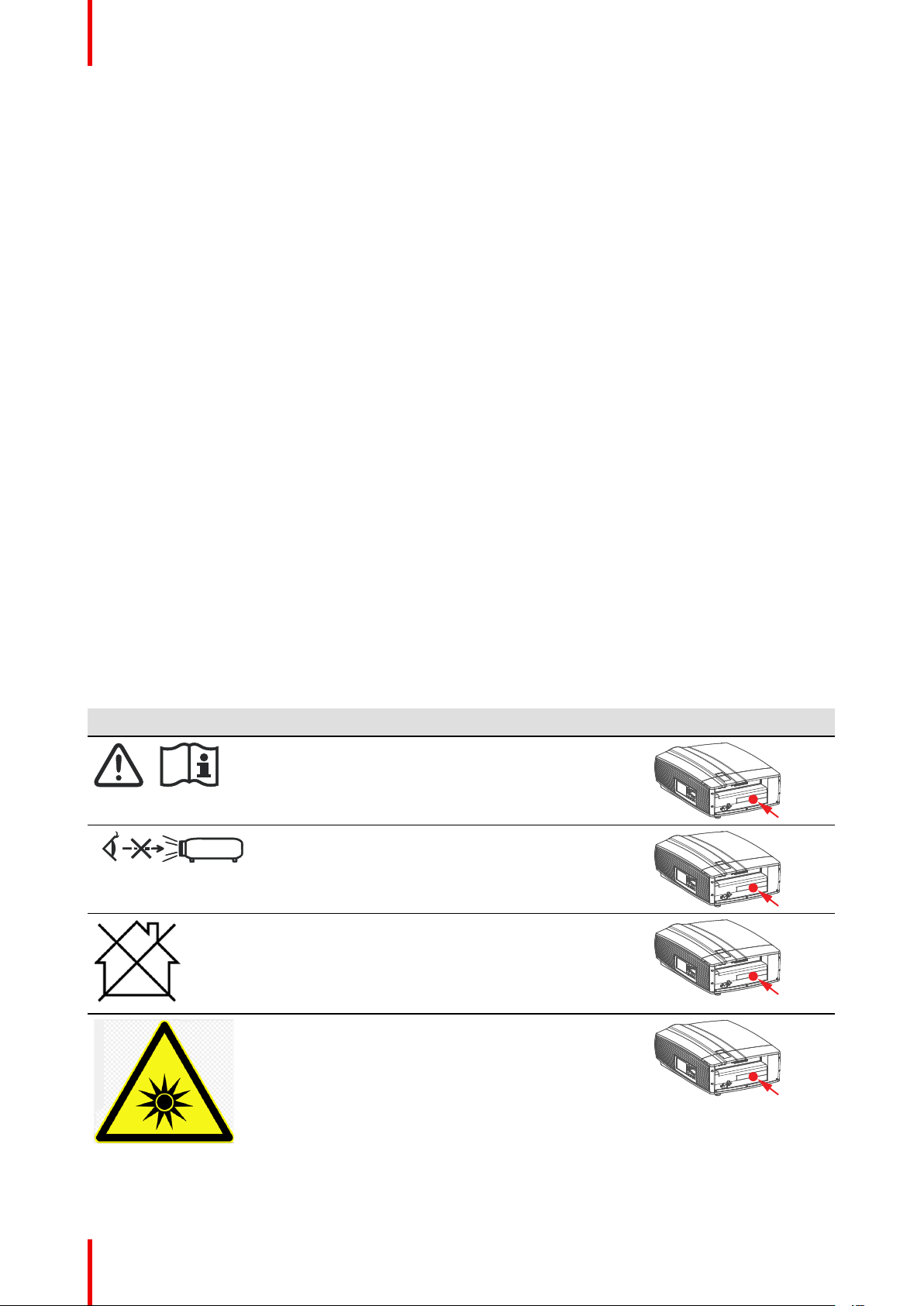
1.3 Product safety labels
Light beam related safety labels
Label image Label description
Refer to user manual for further information!
Caution! Do not stare into beam, RG2 product.
Hazard RG3: not for household use symbol.
Label location
Hazard RG3: optical radiation warning symbol.
R5906852-02 F80 series14
Page 15
837
3
837
3
Safety
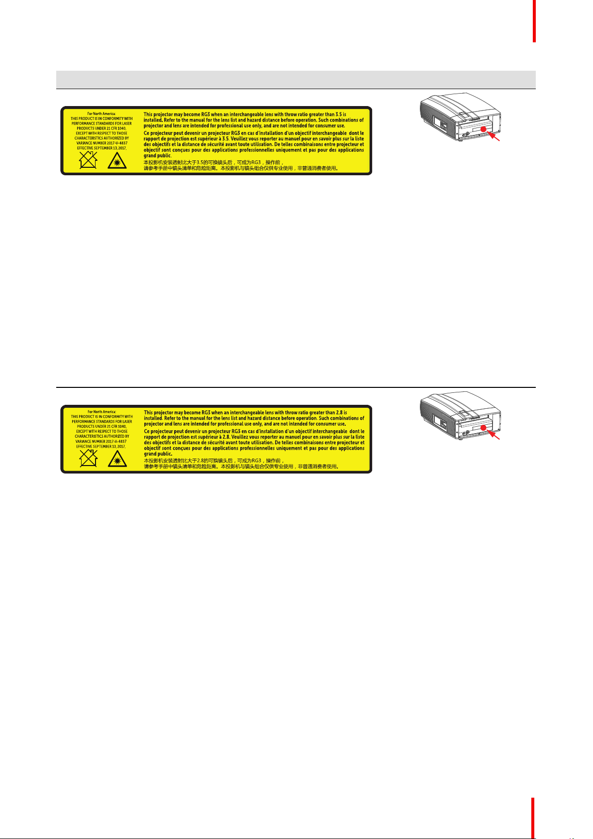
Label image Label description
For F80-Q7, F80-4K7:
For North America: THIS PRODUCT IS IN CONFORMITY WITH
PERFORMANCE STANDARDS FOR LASER PRODUCTS UNDER 21 CFR
1040, EXCEPT WITH RESPECT TO THOSE CHARACTERISTICS
AUTHORIZED BY VARIANCE NUMBER 2017-V-4837 EFFECTIVE
September 13, 2017.
This projector may become RG3 when an interchangeable lens with throw
ratio greater than 3.5 is installed. Refer to the manual for the lens list and
hazard distance before operation. Such combinations of projector and lens are
intended for professional use only, and are not intended for consumer use.
Ce projecteur peut devenir un projecteur RG3 en cas d'installation d'un objectif
interchangeable dont le rapport de projection est supérieur à 3.5. Veuillez vous
reporter au manuel pour en savoir plus sur la liste des objectifs et la distance
de sécurité avant toute utilisation. De telles combinaisons entre projecteur et
objectif sont conçues pour des applications professionnelles uniquement et
pas pour des applications grand public.
本投影机安装透射比大于3.5的可换镜头后,可成为RG3,操作前, 请参考手
册中镜头清单和危险距离。本投影机与镜头组合仅供专业使用,非普通消费者
使用。
For F80-4K9, F80-Q9 :
Label location
For North America: THIS PRODUCT IS IN CONFORMITY WITH
PERFORMANCE STANDARDS FOR LASER PRODUCTS UNDER 21 CFR
1040, EXCEPT WITH RESPECT TO THOSE CHARACTERISTICS
AUTHORIZED BY VARIANCE NUMBER 2017-V-4837 EFFECTIVE
September 13, 2017.
This projector may become RG3 when an interchangeable lens with throw
ratio greater than 2.8 is installed. Refer to the manual for the lens list and
hazard distance before operation. Such combinations of projector and lens are
intended for professional use only, and are not intended for consumer use.
Ce projecteur peut devenir un projecteur RG3 en cas d'installation d'un objectif
interchangeable dont le rapport de projection est supérieur à 2.8. Veuillez vous
reporter au manuel pour en savoir plus sur la liste des objectifs et la distance
de sécurité avant toute utilisation. De telles combinaisons entre projecteur et
objectif sont conçues pour des applications professionnelles uniquement et
pas pour des applications grand public.
本投影机安装透射比大于2.8的可换镜头后,可成为RG3,操作前, 请参考手
册中镜头清单和危险距离。本投影机与镜头组合仅供专业使用,非普通消费者
使用。
R5906852-02 F80 series 15
Page 16
Safety
1.4 Risk Group 3 Safety
1.4.1 General considerations
Notice on optical radiation from F80 Projector when it becomes Risk Group 3.
• For RG3, no direct exposure to the beam shall be permitted.
For RG3, operators shall control access to the beam within the hazard distance or install the product at a
height that will prevent eye exposure within the hazard distance.
• This projector has one or several built-in Class 4 laser clusters. Disassembly or modification is very
dangerous and should never be attempted.
• Any operation or adjustment not specifically instructed by the user’s guide creates the risk of hazardous
laser radiation exposure.
• Do not open or disassemble the projector as this may cause damage by the exposure of laser radiation.
FOR PROFESSIONAL USE ONLY means installation can only be carried out by Barco AUTHORIZED
PERSONNEL familiar with potential hazards associated with high intensity light beams.
WARNING: No direct exposure to the beam within the hazard distance shall be permitted, RG3
(Risk Group 3) IEC 62471-5:2015
CAUTION: Use of controls or adjustments or performance of procedures other than those specified
herein may result in hazardous radiation exposure.
1.4.2 High Brightness precautions: Hazard Distance (HD)
HD
Hazard Distance (HD) is the distance measured from the projection lens at which the intensity or the
energy per surface unit becomes lower than the applicable exposure limit on the cornea or on the
skin. The light beam is considered (to be) unsafe for exposure if the distance from a person to the
light source is less than the HD.
Restriction Zone (RZ) based on the HD
The HD depends on the amount of lumens produced by the projector and the type of lens installed. See next
chapter“HD in function of the lens Throw Ratio (TR)”, page 19.
To protect untrained end users (as cinema visitors) the installation shall comply with the following installation
requirements: Operators shall control access to the beam within the hazard distance or install the product at
the height that will prevent spectators' eyes from being in the hazard distance. Radiation levels in excess of
the limits will not be permitted at any point less than 2.0 meter (SH) above any surface upon which persons
other than operators, performers, or employees are permitted to stand or less than 1.0 meter (SH) lateral
separation from any place where such persons are permitted to be. In non-cinema environments where
unrestrained behavior is reasonably foreseeable, the minimum separation height should be greater than or
equal to 3.0 meter to prevent potential exposure, for example by an individual sitting on another individual's
shoulders, within the HD.
These values are minimum values and are based on the guidance provided in IEC 62471-5:2015 section
6.6.5.
The end user must understand the risk and apply protective measures based upon the hazard distance as
indicated on the label and in the user information. Installation method, barriers, detection system or other
applicable control measure shall prevent hazardous eye access to the radiation within the hazard distance.
For example, projectors that have a HD greater than 1 m and emit light into an uncontrolled area where
persons may be present should be positioned in accordance with “the fixed projector installation” parameters,
resulting in a HD that does not extend into the audience area unless the beam is at least 2.0 meter above the
floor level. In non-cinema environments where unrestrained behavior is reasonably foreseeable, the minimum
separation height should be greater than or equal to 3.0 meter to prevent potential exposure, for example by
an individual sitting on another individual's shoulders, within the HD. For example, a sufficiently large
separation height may be achieved by mounting the image projector on the ceiling or through the use of
physical barriers.
R5906852-02 F80 series16
Page 17
RA
TH
PR
RZ
HD
SW
1m
SW
SW
SW
HD
EXIT
SH
RA
TH
RZ
SH
(B) TOP VIEW(A) SIDE VIEW
PR
RESTRICTED
AREA
RESTRICTED
AREA
Safety
For applications installed in the USA market the above limits for cinema like environments do not apply. The
relevant minimum separation height is 2.5m (8,2 ft) by the FDA CDRH. Non cinema like environments require
2.5 meter (8.2 ft) separation height and 1.0 meter (3.3 ft) separation width for areas where restrained behavior
is to be expected. All other areas require 3.0 (9.9 ft) separation height.
Image 1-1
A Side view.
B Top view.
RA Restricted Access location (boot area of
projector).
TH Theater.
RZ Restriction Zone in the theater.
SH Separation Height.
SWSeparation Width.
PR Projector.
Based on national requirements, no person is allowed to enter the projected beam within the zone between
the projection lens and the related hazard distance (HD). This shall be physically impossible by creating
sufficient separation height or by placing barriers. The minimum separation height takes into account the
surface upon which persons other than operator, performers or employees are permitted to stand.
OnImage 1-2 a typical setup is displayed. It must be verified if these minimum requirements are met. If
required a restricted zone (RZ) in the theater must be established. This can be done by using physical barrier,
like a red rope as illustrated in Image 1-2.
The restricted area sticker can be replaced by a sticker with only the symbol.
Image 1-2
R5906852-02 F80 series 17
Page 18
RA TH
sw
PD
HD
DIFFUSE
sw
RZ
sw
sw
PR
HD
REFLECTION
RESTRICTED
AREA
RESTRICTED
AREA
Safety
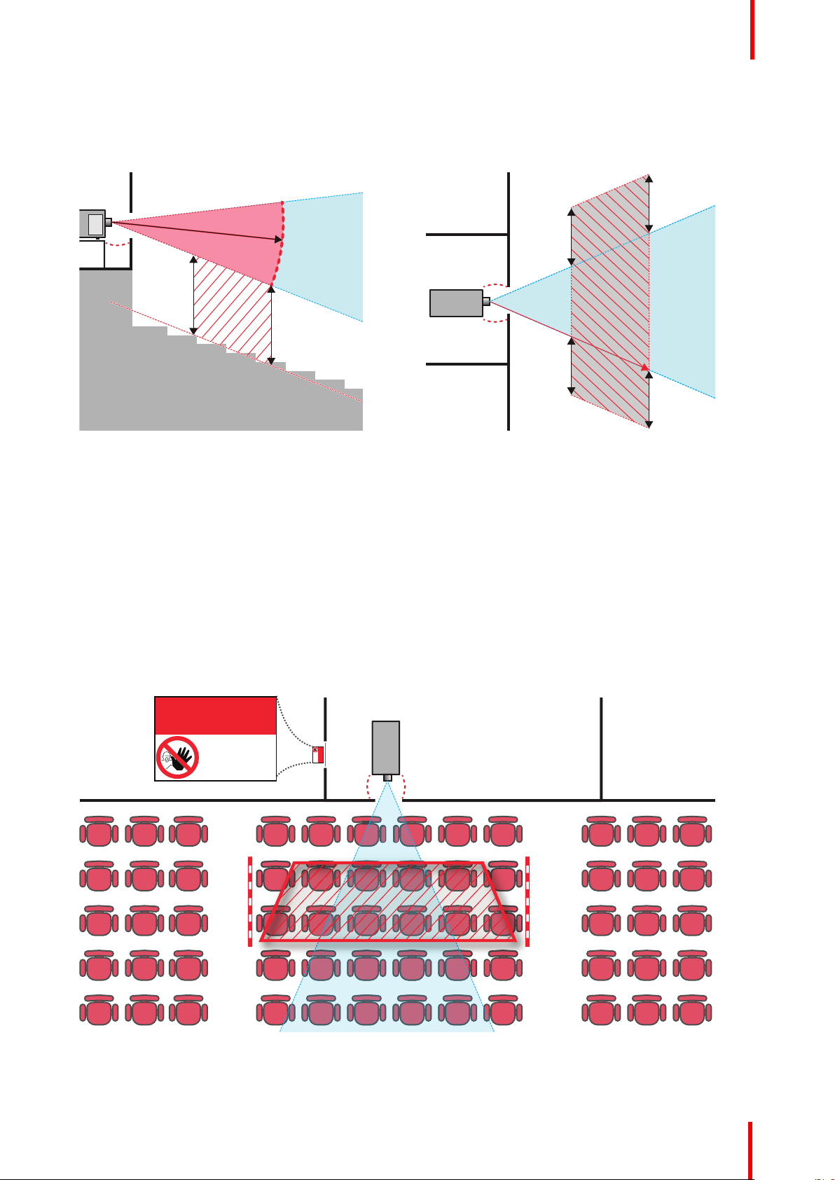
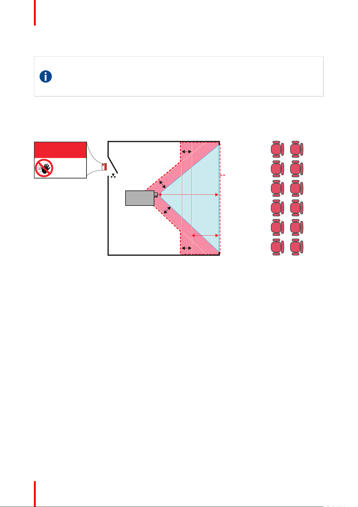
1.4.3 HD for fully enclosed projection systems
HD
Hazard Distance (HD) is the distance measured from the projection lens at which the intensity or the
energy per surface unit becomes lower than the applicable exposure limit on the cornea or on the
skin. The light beam is considered (to be) unsafe for exposure if the distance from a person to the
light source is less than the HD.
Restriction Zone (RZ) based on the HD
The projector is also suitable for rear projection applications; projecting a beam onto a defuse coated
projection screen. As displayed in Image 1-3 two areas should be considered: the restricted enclosed
projection area (RA) and the observation area (TH).
Image 1-3
RA Restricted Access location (enclosed projection
area).
PR Projector.
TH Theater (observation area).
For this type of setup 3 different HD shall be considered:
• HD as discussed in “High Brightness precautions: Hazard Distance (HD)”, page 16, relevant for intrabeam
exposure.
• HD
screen.
• HD
screen.
As described in “High Brightness precautions: Hazard Distance (HD)”, page 16, it is mandatory to create a
restricted zone within the beam areas closer than any HD. In the enclosed projection area the combination of
two restricted zones are relevant: The restricted zone of the projected beam toward the screen; taking into
account 1 meter Separation Width (SW) from the beam onward. Combined with the restricted zone related to
the rear reflection from the screen (HD
The HD
distance to the rear projection screen. To determine the HD distance for the used lens and projector model see
graphs in chapter “HD in function of the lens Throw Ratio (TR)”, page 19.
HD
reflection
The light emitted from the screen within the observation shall never exceed the RG2 exposure limit,
determined at 10 cm. The HD
cd/m² or 15000 LUX.
RZ Restriction Zone.
PD Projection Distance.
SWSeparation Width. Must be minimum 1 meter.
: the distance that has to be kept restrictive related to the reflected light from the rear projection
reflection
: the relevant distance to be considered while observing the diffuse surface of the rear projection
diffuse
); also taking into account a 1 meter lateral separation.
reflection
reflection
distance equals 25% of the difference between the determined HD distance and the projection
= 25% (HD – PD)
can be neglected if the measured light at the screen surface is below 5000
diffuse
R5906852-02 F80 series18
Page 19
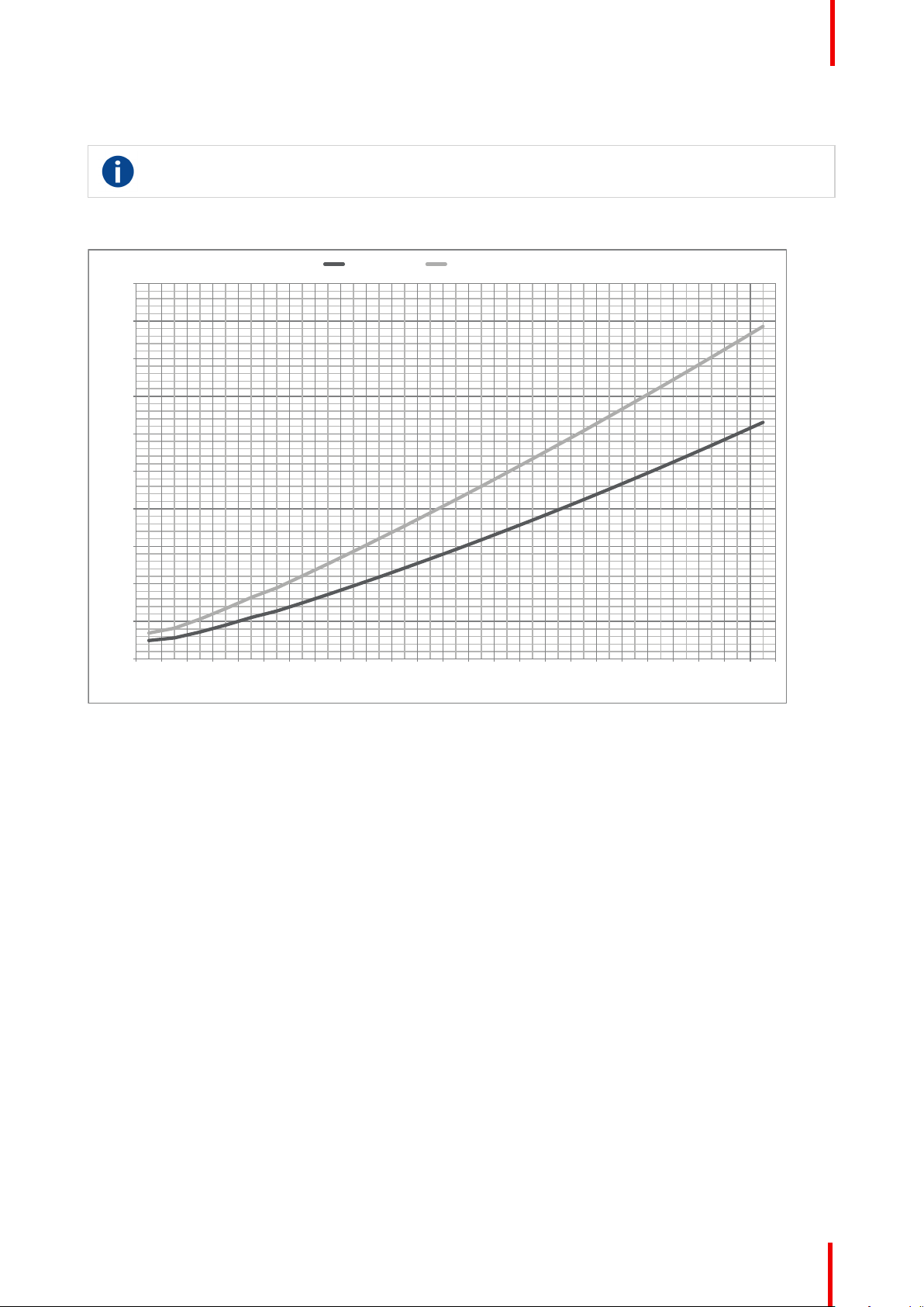
1.4.4 HD in function of the lens Throw Ratio (TR)
0
0.5
1
1.5
2
2.5
3
3.5
4
4.5
5
0.4 0.8 1.2 1.6 2.0 2.3 2.7 3.1 3.5 3.9 4.3 4.7 5.1 5.5 5.9 6.3 6.7 7.1 7.5 7.9 8.3 8.7 9.1 9.5 9.9
Hazard distance [m]
Throw Ra!o
F80-Q7, F80-4K7 F80-Q9, F80-4K9
TR (Throw Ratio)
The ratio of the distance to the screen (throw) to the screen width.
HD versus Throw Ratio
Safety
Image 1-4
Graph shows Hazard Distance in meters versus Throw ratio of the lens
R5906852-02 F80 series 19
Page 20

Safety
R5906852-02 F80 series20
Page 21

Remote Control Unit 2
21R5906852-02 F80 series
Page 22
1
2
+
-
-
+
+
-
-
+
1
2
Remote Control Unit
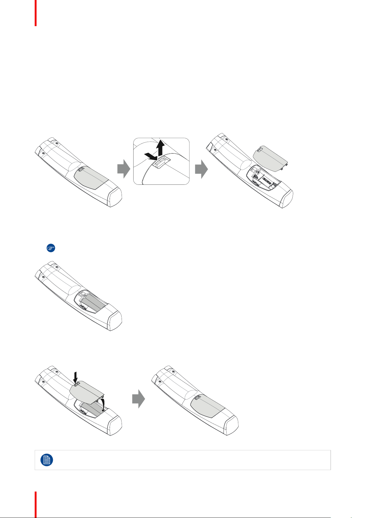
2.1 Remote control, battery installation
Where to find the batteries for the remote control ?
The batteries are not placed in the remote control unit to avoid control operation in its package, resulting in a
shorter battery life time. At delivery the batteries can be found in a separated bag attached to the remote
control unit. Before using your remote control, install the batteries first.
How to install
1. Push the battery cover tab with the fingernail a little backwards (1) and pull, at the same time, the cover
upwards (2).
Image 2-1
2. Insert the two AA size batteries, making sure the polarities match the + and - marks inside the battery
compartment.
Tip: Use alkaline batteries for optimum range and life time.
Image 2-2
3. Insert (1) both lower tabs of the battery cover in the gaps at the bottom of the remote control, and press (2) the
cover until it clicks in place.
Image 2-3
R5906852-02 F80 series22
When replacing batteries, the broadcast address of the RCU will be reset to its default value '0'.
Page 23
CAUTION: Replace with the correct battery type. Use two AA size batteries. There is a risk of
2
1
explosion if the battery is replaced with an incorrect type.
CAUTION: Replace the battery as explained above. There is a risk of explosion if the battery is
incorrectly installed.
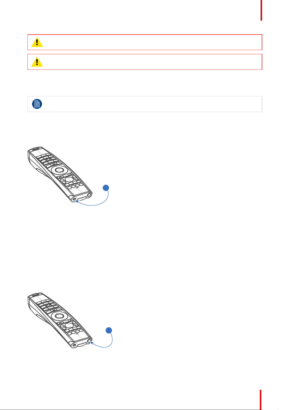
2.2 Using the mini-jack connector of the RCU
Connecting a cable with the mini-jack connector will reset the broadcast address of the RCU to its
default value '0'.
How to use the mini-jack connector
1. Connect a cable with the mini-jack connector (reference 2 Image 2-4) of the RCU.
2. Connect the other end of the cable with the mini-jack input of the projector.
Remote Control Unit
Image 2-4
2.3 Remote control, on/off button
Purpose of the remote control on/off button
The Pulse remote control unit has at the front side an on/off switch (reference 1 Image 2-5). Switching off the
remote control prevents that unwanted commands are send due to an accidental key press. Furthermore,
switching the RCU off will extend the battery life time of the remote control.
To activate the remote control press the on/off button.
To deactivate the remote control press the on/off button again.
Default when (re)placing batteries, is “ON”.
Image 2-5
R5906852-02 F80 series 23
Page 24

Remote Control Unit
R5906852-02 F80 series24
Page 25

Input & Communication
Overview
•
Introduction
• Connection Panel
• Making connections
• Connector specifications
• Control interfaces
• LED and Button indication chart
3
R5906852-02 F80 series
25
Page 26
1 2
1 3 6 8
2 4 5 7 9 1110 12
Input & Communication
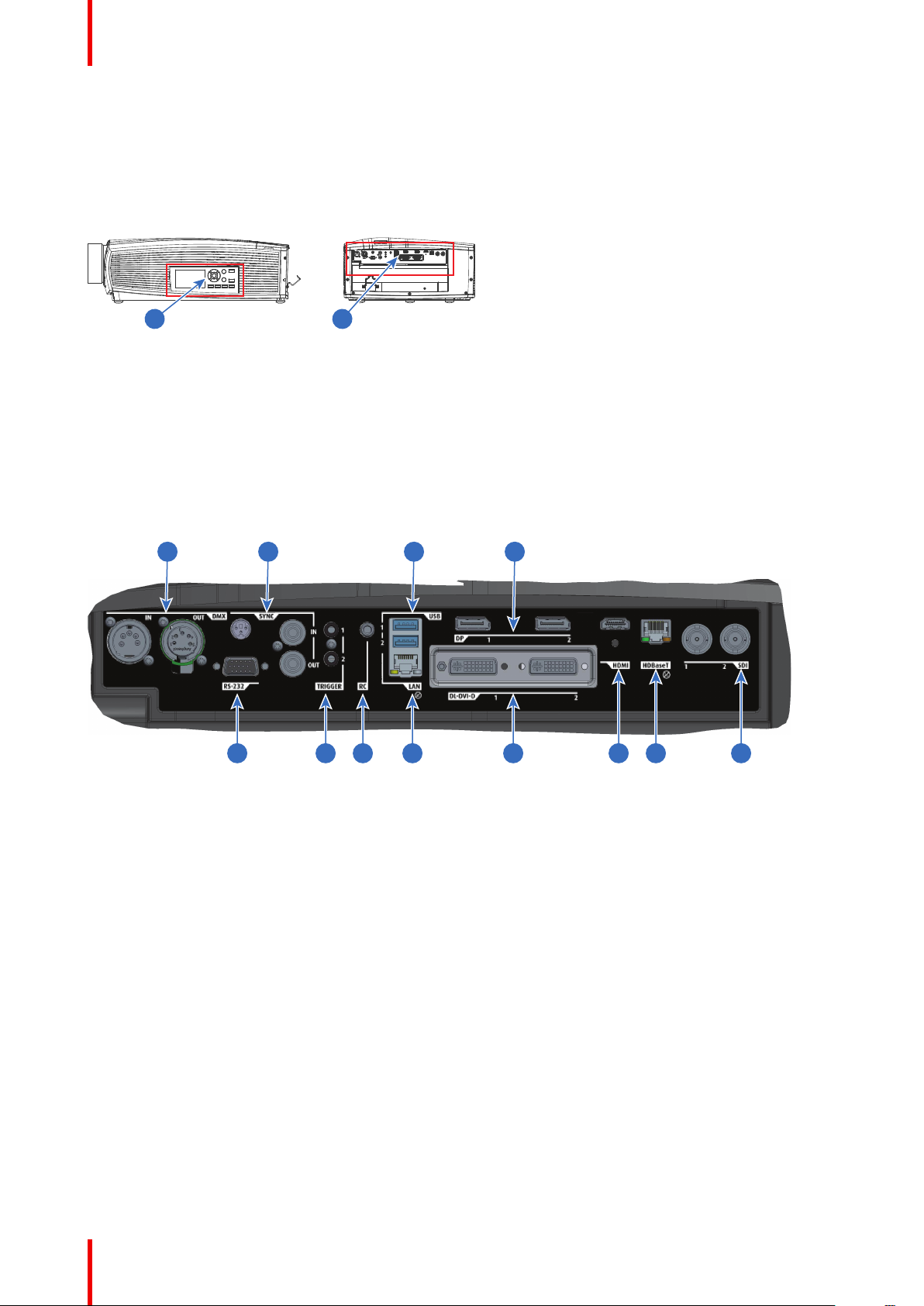
3.1 Introduction
General
The Input & Communication features of the projector consists of a local keypad and a communication panel
situated at the left side, and a connection panel (sources and control connections) located at the back side.
Image 3-1
1 local keypad and a communication panel
2 connection panel
3.2 Connection Panel
General
Projector sources and control connections are located at the back of the projector.
Image 3-2
Nb.Name Pcs
1 DMX IN/
OUT
2 RS-232 1 9–pin DB9 connector For Projector Control. Allows for wired remote
3 Sync 3 BNC Sync Port IN/OUT;
4 Trigger 2 12VDC - 0,5A (6W) For Controlling Peripherals, like motorized
5 RC 1 Mini jack 3,5mm connector for
6 USB 2 USB 2.0 type A, 4 pin( 2x
7 LAN 1 Standard RJ45 connector For Projector Control
2 DMX 512 input / DMX 512
Description Purpose
For Projector Control
output
control and monitoring of many projector
functions used in installation environments
For Projector Control. This is mainly used in
Bidirectional mini-DIN (1x 3D
sync Out, and 2x Sync In/Out)
wired remote
Rear and 1x Front)
multiple projector installations with requirement of
synchronization between the units
screens, curtains etc. Give 12V output when
projector are switched onSee also the note
below.
For Projector Control
For Software upgrade
R5906852-02 F80 series26
Page 27
Input & Communication
Nb.Name Pcs
8 DP 2 Standard display port For Projector Input
9 DL-DVI-D 2 Dual DVI-I 1.0 (DVI_D
10 HDMI 1 Standard HDMI 2.0 For Projector Input
11 HDBaseT 1 Standard RJ45 8P8C
12 SDI 2 SDI1 is Input, SDI 2 is pass
Regarding the Trigger Output: If these outputs are loaded too heavy, there is a risk that the projector
will go in reset mode, and restart. This causes no damage to the projector, but is an undesirable
response. This will also happen if the startup current for the external equipment is too high, even
though the nominal power consumption is less than 0,5A.
Description Purpose
For Projector Input. These connectors can also
Functionallity).
Connector
through. (out)
be used to form one uniform image by feeding
half of the image into each connector. HDCP
compliant for sources up 165 Mhz
For Projector Control
For Projector Input
3.3 Making connections
The source switching time is variable and could take few seconds..
Source signal connectivity
The connector panel at the back of the projector is used for all source connections.
Source signal connectivity on the projector is:
• 2x Dual Link DVI-I (DVI-D functionality)
• 2x DisplayPort 1.2
• 1x HDMI 2.0
• 1x HDBaseT
• 1x SDI input (initially designed for 3G-SDI input signals, 12G-SDI signals are now supported)
3.4 Connector specifications
Overview
•
DVI-I
• Display Port 1.2
• HDMI 2.0
• SDI
• HDBase T
3.4.1 DVI-I
Specifications
Parameter Value
Connector DVI-I female digital RGB
Signal characteristics DVI 1.0, Digital, TMDS
Max. cable length 25 m (24 AWG)
R5906852-02 F80 series 27
Page 28
Input & Communication
Parameter Value
Max. pixel rate 330 MHz (dual link), 165 Mhz (single link)
Scan format Progressive
Max. input data resolution 1920x1200 60Hz (Single link), 2560x1600 60Hz
(Dual Link).1920x2400 @60Hz
Bit depth 8 bit
EDID Supported
HDCP Supported
3.4.2 Display Port 1.2
Specifications
Parameter Value
Connector Standard Display port
Signal characteristics DP 1.2
Functionality Mandatory
Max. cable length 2 m (24 AWG) - RBR;
2 m (24 AWG) – HBR1, HBR2
Supported Link Rate RBR, HBR1, HBR2
Scan format Progressive
Max. input data resolution 2560x1600@120Hz WQXGA / 3840x2400 @60Hz
(4K ) Max
Bit depth 8, 10, 12 bit
EDID Supported
3.4.3 HDMI 2.0
Specifications
Regarding HDMI 2.0: The decryption protocol HDCP 2.2 are enabled and valid in this unit.
Parameter Value
Connector Standard HDMI
Signal characteristics Digital, TMDS
Max. cable length 2 m (24 AWG)
Max. pixel rate 594MHz
Max. input data resolution 3840x2160 @60Hz
Bit depth 8, 10, 12 bits
EDID Supported
HDCP Supported
Ethernet No
Audio return No
R5906852-02 F80 series28
Page 29
Input & Communication
3.4.4 SDI
Specifications
Parameter 12G-SDI 3G-SDI
Standard SMPTE ST-2082-1 and ST-2082-10
standards
Connector Samtec BNC7T-J-P-HN-RA-BH1 1x) BNC 75 ohm type IEC 60169-8,
Bandwidth 12GHz >3 GHz
Return loss -6dB @ 12GHz >10dB at 3GHz
Impedance 75 ohm resistive 75 ohm resistive
SMPTE 424M-2006 10bit level A
Amendment 2 1997, A
3.4.5 HDBase T
Specifications
Parameter Value
Reference specification HDBaseT 1.0 Specification, June 2010
Connector Standard RJ-45, 8P8C
Signal characteristics HDBaseT
Max. cable length (1080p/48b/60Hz) 100 m (Cat5e/6), Pixel Clock <=225HHz, Video
Datarate <=5.3Gbps
70 m (Cat5e/6), Pixel Clock >225HHz, Video
Datarate >5.3Gbps
100 m (Cat6a/7), Pixel Clock >225HHz, Video
Datarate >5.3Gbps
Max TMDS Clock Frequency 270 MHz
Max video resolution supported 1920x1200 @60Hz (WUXGA 60Hz)
HDCP Pass-Through Yes, from Source to Projector
IR Extension Not Supported
RS-232 Extension Not Supported
10/100Mbps Ethernet Pass-Through Not Supported
Fallback to 100BaseTx, IEEE 802.3u Not Supported
USB Over Centre Tap Not Supported
Power Over Ethernet Not Supported
Audio Not Supported
LEDs - HD Base Status Operation: Green, Left
Link/Mode: Yellow, Right
3.5 Control interfaces
About
The following control interfaces are available on the projector:
• 1x RS-232 (for projector control)
• 1x LAN/Ethernet (for projector control
R5906852-02 F80 series 29
Page 30
Input & Communication
• 3x USB-A ports
Overview
•
RS-232
• LAN/Ethernet
• USB-A port
3.5.1 RS-232
Specifications
Parameter Value
RS-232 connector 1 female DB9 connector (RS232-in) for projector
control and debug
3.5.2 LAN/Ethernet
Specifications
Parameter Value
Ethernet connector 1 RJ45 Connector for projector control (not content)
Protocols DHCP, TCP/IP, UDP/P
Speed 10/100 Mbit/1000Mbit
3.5.3 USB-A port
Specifications
Parameter Value
USB connector Type A
Function Firmware upgrade using USB sticks
Power Power 5V, max 1,5A (out)
Standard USB 2.0
3.6 LED and Button indication chart
Button Backlight Status
Button Color status
Standby button
Shutter button
Blinking WHITE (slow) Projector starts up (booting)
Blinking WHITE (fast) Firmware upgrade
Solid WHITE Projector is in Standby mode
Blinking BLUE Projector goes to ON mode
Solid BLUE Projector is ON
Blinking RED Error condition
Off (no color) Projector is OFF, starts up, or is in
Solid WHITE Projector is ON, shutter is open
Solid RED Projector is ON, shutter is closed
Description
Standby mode.
R5906852-02 F80 series30
Page 31

Input & Communication
LED Status
The LED status is located on the top side of the projector, near the IR receiver.
During normal operation the LED is unlit. In the event of a critical error or high temperature, the LED will
display red.
By critical error, the projector cannot be restarted until the projector is disconnected from the power supply and
then reconnected again. If the reason for the error persist, the projector will again go to critical error status.
By high temperature, the projector will restart when it has cooled down, and temperatures are back within the
normal operating limitations.
R5906852-02 F80 series 31
Page 32

Input & Communication
R5906852-02 F80 series32
Page 33

Getting Started 4
About this chapter
This chapter describes how to power up, control and set up your projector setup when the physical installation
process is complete.
How controlling the projector ?
The projector can be controlled by the local keypad, by the remote control unit or by browser application.
Location of the local keypad ?
The local keypad is located on the right side of the projector.
Remote control functions.
This remote control includes a battery powered infrared (IR) transmitter that allows the user to control the
projector remotely. This remote control is used for source selection, control, adaptation and set up.
Other functions of the remote control are :
• switching between stand by and operational mode.
• switching to "pause" (blanked picture, full power for immediate restarting)
• direct access to all connected sources.
Overview
•
Functionality overview
• Power modes
• Power mode transitions
• Status overview
• Power off projector
• Increasing the projector life time
• Operation in 24/7 Mode
• Using the RCU
• Projector Address
• Quick setup via Direct access
R5906852-02 F80 series
33
Page 34

1
1 2 3 4 5 6
1011 9 8 7
2
3
4
5
6
7
8
9
10
11
Getting Started
4.1 Functionality overview
Local Keypad overview
Menu navigation
Menu confirmation, OK
button
Menu Open / Close
Menu back
Power On/Off
Project OSD On / Off
Input selection
Shutter open / close
Test patterns
Lens adjustment
LCD panel
The Keypad gives direct access to several functions, in addition to access to the menu system.
The keypad has a back light that can be switched on and off manually. The light turns off automatically after a
preselected time.
The Power button and Shutter buttons are equipped with white, blue and red backlit LEDs. The other keys are
only equipped with white and blue backlit LEDs. The LEDs are controlled according to the features available.
R5906852-02 F80 series34
Page 35

Remote Control Unit buttons
1
2
3
4
5
6
7
8
9
10
11
12
15
24
23
22
21
20
19
18
17
16
13
14
2625
1
14
2
15
3
16
4
17
5
18
6
19
7
20
8
21
9
22
10
23
11
24
12
25
13
26
Getting Started
Button pressed indicator
Shutter open
Shutter close
LCD panel On / Off
Project OSD On/Off
Lens zoom
Lens shift
Menu Open / Close
Menu selection, OK
button
Menu navigation
Input selection
Address button
Numeric buttons
Backspace (while
entering values)
XLR connector
Decimal mark (while
entering values)
Macro button
Menu back
Default value button
Lens focus
RGB filter
Test patterns
Power On
Power Off
3.5 mm jack
RCU On / Off
The projector remote control is a full feature wireless remote control, powered by two (2) standard AA
batteries. The battery compartment is on the back of the remote control.
The remote control is backlit for use in dark environments. It also has an XLR connector for wired connection
to the projector. When the wire is connected, the IR beam is switched off.
LCD panel
The LCD panel has two main functions:
1. Showing the menus, the adjustment information and also a mirror of the OSD, (On Screen Display)
described in User Interface when this is enabled.
Information regarding the status of the projector showing this data:
• Projector status
• Network address
• Active source
• Current firmware version
• Operation Data
• Active functions (Enabled Functions).
Toggle between the two indications by using the Menu button on the keypad, or on the remote control.
The LCD Display will fade out 30 seconds after the last key operation.
4.2 Power modes
General
The table below details the F80 power modes.
R5906852-02 F80 series 35
Page 36

2
ECO
READY
ON
1%
50%
50%
Getting Started
Mode
ON (normal) Projector is booted up and the light source is on
READY Projector is booted up but the light source is off
ECO (Standby) Light source is switched off and projector electronics
Energy consumption is significantly lowers in ECO (Standby) mode: only <0.5W if network is not
plugged in and 2W with network (Wake-on-LAN).
In ECO (Standby) mode, remote power up (Wake-on-LAN) and local power up (button) are
supported.
Description
are powered down
4.3 Power mode transitions
4.3.1 General
Transition Diagram
This diagram shows all modes available on the projector (unplug, ON, READY, ECO), and the actions
necessary to change mode.
Image 4-1
-
Projector mains powered
-
Auto transition after x minutes if ECO mode enables
-
Press power On/Off button, remote On/Off button
4.3.2 Power on projector
If not already connected, connect the female side of the power cord with the power input socket of
the projector. For more details see section dedicated to the power cord installation.
R5906852-02 F80 series36
Page 37

Getting Started
The background image of the startup screen and info screens can be changed with Projector
Toolset with an installed F80 plug-in.
Description
Plug the 3-prong plug of power cord into a grounded AC outlet. The projector will go to READY mode. During
this stage the system boots and performs the internal check of the boards. The Power On/Off button will
BLINKING WHITE until READY mode is achieved. Once in READY mode, the Power On/Off button will be lit
WHITE.
4.3.3 Going from READY to ON
Description
Press the Power On/Off button on the projector, or the Power On button on the remote control. The projector
will power ON. The Power On/Off button will BLINK BLUE during the transition from READY to ON. Once the
projector is on, the Power On/Off button will be lit BLUE.
4.3.4 Going from ON to READY
Description
Press and hold the Power on/off button on the projector for 3 seconds, or press the Power Off button on the
remote control. The projector will power down through a cool down phase. The Power on/off button will BLINK
WHITE during the transition from ON to READY. Once the projector is in READY, thePower on/off button will
be lit WHITE.
4.3.5 Going from READY to ECO standby
Description
If ECO Standby mode is enabled in the service menu (refer to the section "GUI - system settings/Standby
ECO", in User Guide) the projector will automatically go to ECO standby mode after a time-out (default 15
minutes). All electronics (including fans, pumps,...) go down except for a very small wake up controller. The
Power on/off button will FLASH WHITE every second.
4.3.6 Going from ECO to ON
Description
Press the Power on/off button on the projector or the Power On button on the remote control. The projector
goes from ECO directly to ON. The projector will go through the same booting phase as on power plugging,
then do the transition from READY to ON. Of course startup-time will be longer then from READY to ON.
4.3.7 Wake on LAN (WOL)
Description
Wake-on-LAN (WOL), the standard ethernet network command, can be used to awakened or to turn on the
projector by network message.
Used alone, the WOL command allows to switch in READY mode. A JSON command must be performed in
addition to make the projector turn in to ON mode:
1. Send WOL.
2. Wait for connection to façade/prospector (the unit does provide feedback when it’s ready).
3. Wait for ready state.
4. Sleep 5 seconds.
R5906852-02 F80 series 37
Page 38

Getting Started
5. Send power on command (to switch in ON mode).
4.4 Status overview
Description
Once the projector is started, press Status to get an overview of parameters such as :
• Chosen source
• Current resolution and refresh rate
• Device serial number and article number
• Current firmware version and model name
• Current illumination (in percentage)
• Lamp runtime in hours
• Chosen communication method and IP address (if connected)
• Warp status
• Environmental temperature
Image 4-2
4.5 Power off projector
How to Switch off the projector
1. Use the standby button, or the Power On button on the remote control, to switch off the projector.
The projector will switch to READY mode first in order to run through a cool down phase (see “Power mode
transitions”, page 36).
2. If ECO Standby mode is enabled in the service menu (refer to the section "GUI - system settings/Standby
ECO", in User Guide) the projector will automatically go to ECO standby mode after a time-out (default 15
minutes).
Some actions like apply a grey test pattern are done during the two minutes of the cool down phase
in order to minimize the potential effect of burn-in and increase the projector lifetime.
CAUTION: Never switch off the projector by means of unplugging mains cord or by cut down of
mains power.
Barco advises to keep the projector always powered and use the ECO mode for low power
consumption.
R5906852-02 F80 series38
Page 39

Getting Started
How to unplug the projector
1. Follow the procedure above to Switch Off the projector.
2. Wait at least 2 minutes prior to unplug the projector by removing the power cord from the AC outlet.
CAUTION: It is very important to wait few minutes before unplug the power cord. If the cool down
phase is not adhered, projector lifetime could be degraded.
4.6 Increasing the projector life time
General
Barco propose the following recommendations to increase the projector life time:
• Dimming out the laser output intensity (70%).
• Use the device in regulated temperature area.
• Apply the recommendations describe in the “Operating in 24/7 Mode” chapter if the projector is destined to
be operated continuously 24 hours a day / 7 days a week.
Typical life time of the projector could be up to double if the laser output is dimmed to 75% and if the
projector operate in 25°C temp condition.
4.7 Operation in 24/7 Mode
General
When the projector is destined to be operated continuously 24 hours a day / 7 days a week, Barco has a
number of recommendations to increase the projector life time:
• Regularly, preferably twice a day if possible, switch off the projector during two minutes by using the
standby button. The power down action will automatically and invisibly trigger a grey test pattern running
within the projector.
Note: if you really don't want to shut down the projector, an alternative method is select the grey test
pattern yourself within the normal “on” mode. This method is not as effective as completely shut down the
projector, but may be a more workable alternative.
• Apply moving video content as much as possible, with on average a level of 50% white (long-term use of
extreme black or white content could potentially cause accelerated aging).
4.8 Using the RCU
Pointing to the reflective screen
1. Point the front of the RCU to the reflective screen surface.
R5906852-02 F80 series 39
Page 40

1
Getting Started
Image 4-3: IR control via reflective screen
Hardwired to the mini jack input
1. Plug one end of the remote cable in the connector on the front side (3,5mm mini jack) of the RCU.
2. Plug the other end in the connector on the communication interface of the projector, labelled ‘Remote
CTRL’(reference 1, Image 4-4).
Image 4-4
Note: Plugging the remote control will switch the broadcast address of the remote control to the
default value '0'. This is the only broadcast address that will work when hardwired. If you want to
change the broadcast address after disconnecting the remote control, see “Projector Address”, page
41.
Pointing directly to the IR sensor
When using the wireless remote control, make sure you are within the effective operating distance (30m, 100ft
in a straight line). The remote control unit will not function properly if strong light strikes the sensor window or if
there are obstacles between the remote control unit and the projector IR sensor.
R5906852-02 F80 series40
Page 41

F1
F2
F3
F4
F5
A
D
J
E
XIT
E
N
TE
R
P
A
U
SE
P
H
A
S
E
T
E
X
T
S
H
A
R
PN
TI
N
T
C
O
LO
R
B
R
I
G
H
T
N
C
O
NT
R
TR
E
B
LE
B
A
LA
N
C
E
B
A
S
S
VO
L
9
0
7
8
5
6
3
4
1
2
45°
45°
Image 4-5: RCU to one of the IR sensors
Getting Started
4.9 Projector Address
Projector address
Address installed in the projector to be individually controlled.
Broadcast address
Projector will always execute the command coming from a RCU programmed with that broadcast
address.
4.9.1 Controlling the projector
Why a projector address?
As more than one projector can be installed in a room, each projector should be separately addressable with
an RCU or computer. Therefore each projector has its own address.
Set up an individual Projector Address
The set up of a projector address can be done via the software.
Projector controlling
When the address is set, the projector can be controlled now:
• with the RCU: only for addresses between 1 and 31.
Broadcast Address
Every projector has a broadcast (common) address '0' or '1'. The default address is '0'.
The choice between '0' and '1' can be selected in the GUI: “System Settings” → “Communication” →“IR Control
“.
R5906852-02 F80 series 41
Page 42

I
I
Getting Started
Placing new batteries in the remote control or plugging the remote to a projector via a cable will
automatically reset the address back to its default value '0'.
4.10 Quick setup via Direct access
Quick source selection
1. Press the Input button on the remote control or local keypad.
Image 4-6
The Source selection menu opens on the LCD display.
Image 4-7: Input selection
2. Use the arrow keys to select the desired source.
Quick test pattern selection
1. Press the Test pattern button on the remote control or local keypad.
R5906852-02 F80 series42
Page 43

P
P
Image 4-8
The Test pattern menu opens on the LCD display.
Getting Started
2. Use the arrow keys to select the desired test pattern.
R5906852-02 F80 series 43
Page 44

Getting Started
R5906852-02 F80 series44
Page 45

Graphic User Interface (GUI)
Overview
•
Overview
• Navigation
• Test Patterns
5
R5906852-02 F80 series
45
Page 46

1 4
4
2 3
3 2 1
Graphic User Interface (GUI)
5.1 Overview
GUI - Main Menu overview
The projector on screen display (OSD) is the primary user interface (UI). From here, you can review and
adjust all projector and display settings.
The OSD interface uses tabs to display the main menu. Each main menu contains submenus.
The OSD can be disabled by pressing the OSD on/off button.
Image 5-1: Home menu
The projector's software platform uses access levels what each user can do. A standard user has access to all
projector functionality. A certified service technician has also access to the service menu. This menu is
password protected.
5.2 Navigation
Navigation via the RCU or local keypad
Navigating the OSD can be done using the remote control or the local keypad.
Image 5-2
To start up the menu structure, press MENU (1).
Use the arrow keys (Menu Navigation buttons) to navigate to the desired menu item (2). The background
color changes to light blue.
Press the Menu Selection button (center key of the arrow keys), also called OK button, to activate that item
and to jump one level deeper (3).
Use the numeral keys to enter values, or use the arrow keys to move the bar scale up or down.
Press the Back button to go up one level (4).
R5906852-02 F80 series46
Page 47

Graphic User Interface (GUI)
Image 5-3: Home menu
Remark: a blue slider bar on the right side of the window means that there are more items to show than those
currently displayed.
Define values
Menu settings are displayed using check boxes, bar scale sliders, and drop-down lists.
To set a value:
• Press OK to select or deselect a checkbox (turn a function ON or OFF).
• Use the arrow keys to move the bar scale slider up or down on the value line. For a bar scale 0-9, each
step will equal 10% of the total value.
• To enter the value as a direct number, press OK, input the digit(s), and then press OK again to execute and
exit cursor mode e.g. OK 79 OK.
Within an input field, use the * button as backspace button to remove an entered digit. Use the # button to
enter a dot (.).
Changes to values are implemented dynamically.
To enter values with the local keyboard, use the arrow keys to select the first digit, press OK. Select the
second digit and press OK. Continue until all digits are entered. Close the action by selecting the enter (↵)
button and press OK. Select the backspace button and press OK to remove the last entered digit.
Menu memory
The OSD menu remembers the last selected sub-item as long as the projector is running. The menu memory
is reset when restarting the projector from standby.
5.3 Test Patterns
How to use test patterns
1. In the main menu, select Test Patterns.
or
Push the Test Patterns button on the RC or on the local keypad.
Image 5-4: Main menu, Test Patterns
2. In the Test Patterns menu, select either Patterns, Internal, or P7 Calibration test patterns.
3. In the chosen submenu, select the desired test pattern from the list.
R5906852-02 F80 series 47
Page 48

Graphic User Interface (GUI)
You can select one of the following Patterns test patterns:
• Native Black
You can select one of the following Internal test patterns:
• Aspect
• ANSI Lumen
• Cyan
• White
• Magenta
• 3D Stereo
• Checker Board
• Yellow
• Focus
• Red
• Cross hatch
• Mono scope
• Green
• Focus BW
• Color bars
• Blue
You can select one of the following P7 Calibration test patterns:
• Native Red
• Native Green
• Native Blue
• Native White
4. To turn the test pattern off, return to the previous menu.
R5906852-02 F80 series48
Page 49

GUI – Source 6
About the Source menu
This menu is used to select, review and configure sources into the projector.
Overview of features
•
Displaying a single source
• Displaying multiple sources: Stitched layouts
• Connector Settings
R5906852-02 F80 series
49
Page 50

GUI – Source
6.1 Displaying a single source
About selecting a source
Before a source can be projected, the source signal must be connected to the source input (s) of the device
and a valid synchronization signal must be available along with the source signal on at least one of the input
connectors.
How to select?
1. Press Menu to activate the menus and select Source.
Image 6-1: Select Source
2. Press OK.
The Select Source menu is displayed with the actual available sources filled out.
Image 6-2: Input selection menu
3. Select the desired input.
6.2 Displaying multiple sources: Stitched layouts
About stitched layouts
The first time you use a selected single source, the source will be displayed in the projector's native resolution.
If the resolution of the source is different to the projector's resolution, the image is stretched or shrunk.
It is however possible to configure and display two source signals to make up one single image in full native
resolution. This is called a Stitched Layout: the sources are stitched together.
The following table lists which stitched layouts you can use, and in which display mode these layouts can be
used.
The table below describes the different Stitch Layouts and scan directions.
R5906852-02 F80 series50
Page 51

1
1 2
1
GUI – Source
Type of layout Description
A single source is displayed in
full screen
: Single
Two inputs are required. The
sources are displayed next to
each other.
: Dual 1 x 2
Two inputs are required. The
sources are displayed one
above the other.
: 2 x single
How to select a stitched layout
1. Press Menu to activate the menus and select Source.
Available connectors Mode
• SDI
• HDBaseT
• DisplayPort (x2)
• Dual link DVI-D (x2)
• HDMI
• 2x DisplayPort
• 2x dual link DVI-D
• 2 x DisplayPort
• 2x dual link DVI-D,
Mono / Active
stereo
Mono / Active
stereo
Passive stereo
Image 6-3: Select Source
2. Press OK.
The Select Source menu is displayed with the actual available sources filled out, including all available
stitched layout options.
Image 6-4: Input selection menu
3. Select the desired stitched input.
R5906852-02 F80 series 51
Page 52

GUI – Source
Image 6-5: Input Selection menu, stitched options
6.3 Connector Settings
About Connector Settings
The Connector Settings menu allows you to change settings for each input connector of the projector.
By default all options for every connector are set to automatic, together with the native Extended Display
Identification Data (EDID).
When entering the menu for each input connector, you can change the following:
• Color Space
• Signal Range
• EDID
How to configure a connector
1. Press Menu to activate the menus and select Source.
Image 6-6: Select Source
2. Press OK.
The Select Source menu is displayed with the actual available sources filled out.
3. Scroll down to the bottom of the list of available sources and select Connector Settings.
Image 6-7: Source menu, Connector Settings
The available input connectors are displayed.
R5906852-02 F80 series52
Page 53

Image 6-8: Select source
4. Select the desired connector.
The Connector Settings menu for this connector will be displayed.
GUI – Source
Image 6-9: Example of connector settings for an HDMI connector
5. You can change the following:
• To force a limit on the color space, select one of the available color spaces.
• To force a limit on the used signal range, select one of the available signal ranges.
• To set a video timing other than the one native for the connector, select one of the options under EDID.
Note: You cannot change the EDID for SDI connectors.
R5906852-02 F80 series 53
Page 54

GUI – Source
R5906852-02 F80 series54
Page 55

GUI – Image 7
Overview of features
•
Setting image levels manually
• Adjusting the sharpness
• Adjusting the gamma correction
• P7 Realcolor
• Setting the output resolution
• Brilliantcolor
• Displaying HDR content – Perceptual Quantizer (PQ)
R5906852-02 F80 series
55
Page 56

GUI – Image
7.1 Setting image levels manually
Purpose
Contrast: Change the contrast of the complete output signal (main and PiP window together) of the projected
image.
Brightness: Change the brightness of the complete output signal (main and PiP window together) of the
projected image.
Saturation: Change the saturation of the complete output signal (main and PiP window together) of the
projected image.
How to set up Contrast
1. In the main menu, select Image → Contrast.
Image 7-1: Image menu — Contrast
2. Use the ◄ or ► key to change the contrast enhancement until the desired value is reached (adjustable between
0 and 2).
Image 7-2: Contrast slider
3. If necessary, use the ▲ or ▼ key to select the other image adjustment options.
How to set up Brightness Level
1. In the main menu, select Image → Brightness.
Image 7-3: Image menu — Brightness
2. Use the ◄ or ► key to change the brightness until the desired value is reached (adjustable between –1 and 1).
R5906852-02 F80 series56
Page 57

Image 7-4: Brightness slider
3. If necessary, use the ▲ or ▼ key to select the other image adjustment options.
How to set up Saturation Level
1. In the main menu, select Image → Saturation.
GUI – Image
Image 7-5: Image menu — Saturation
2. Use the ◄ or ► key to change the saturation until the desired value is reached (adjustable between 0 and 2).
Image 7-6: Saturation slider
3. If necessary, use the ▲ or ▼ key to select the other image adjustment options.
7.2 Adjusting the sharpness
About adjusting the sharpness
The sharpness adjustment amplifies the high frequency components in the picture. This means that by
increase the sharpness, the picture will be perceived as sharper, and if decreased, the picture will be
perceived as more blurry.
Increasing the sharpness will have the best effect in high contrast images, eg a table with text and borders.
In a natural picture, high sharpness can be perceived as noise, as all details in the picture will be amplified.
Available range: -2 to 8.
Default value: 0
R5906852-02 F80 series 57
Page 58

GUI – Image
Image 7-7: Effect of sharpness adjust
How to adjust
1. In the main menu, select Image → Advanced → Sharpness.
Image 7-8: Image menu — Sharpness
2. Use the ◄ or ► key to change the sharpness until the desired value is reached.
Image 7-9: Sharpness slider
3. If necessary, use the ▲ or ▼ key to select the other image adjustment options.
7.3 Adjusting the gamma correction
About gamma correction
Gamma correction is an image quality enhancement function that offers a richer image by brightening the
already darker portions of the image without altering the brightness of the brighter portions (contrast feeling
enhanced).
How to adjust
1. In the main menu, select Image → Advanced → Gamma.
R5906852-02 F80 series58
Page 59

Image 7-10: Advanced menu – Gamma
2. Use the ◄ or ► key to change the gamma value between 1.0 and 2.8 . The default value is 2,2.
Tip: The slider can be adjusted with a precision of 0.1.
GUI – Image
Image 7-11: Gamma slider
3. If necessary, use the ▲ or ▼ key to select the other image adjustment options.
7.4 P7 Realcolor
Purpose
When blending images from multiple projectors, the perceived color coordinates of each projector can be
altered to a desired common level, so that the projected colors are identical over all projectors used.
Alternatively, if you are unfamiliar with how adjusting the Colors to a specific setting, there are also a certain
number of presets available, which forces the color output to specific color standards.
The selection of the presets will vary, depending on the projector type and on the peripherals installed.
How to set custom P7 values
1. In the main menu, select Image → Advanced → P7 Realcolor.
Image 7-12: Advanced menu — P7 Realcolor
The P7 menu is displayed.
R5906852-02 F80 series 59
Page 60

GUI – Image
Image 7-13: P7 Realcolor menu
2. Select the desired Mode. Choose one of the following custom options:
• Custom RGB: 3–point color configuration.
In RGB mode, the C, M and Y coordinates will be calculated automatically based on the R, G and B
coordinates.
• Custom RGBCMY: 6–point color configuration (both RGB and CMY).
In RGBCMY mode, each color can be given a specific coordinate within the measured color triangle.
• Custom WHITE: Configure only the White temperature.
3. Define the coordinates for each available color.
Click on a coordinate value and select the current value. Enter the desired value with the numeric keys.
Note: You can only pick coordinates within the measured color triangle.
4. For Custom White, click on White point and choose one of the following:
• Coordinates: Configure the white point via specific coordinates.
The white point is specified using an x, y coordinate in the CIE 1931 Chart.
• Temperature: Configure the white point via a color temperature slider.
The white point is specified on a Kelvin scale between 3200K and 13000K tracking along the black body
curve.
You can reset all coordinates to the default values (to native) by selecting Reset modes to native.
Press OK button to reset.
How to choose one of the P7 presets
1. In the main menu, select Image → Advanced → P7 Realcolor.
Image 7-14: Advanced menu — P7 Realcolor
The P7 menu is displayed.
R5906852-02 F80 series60
Image 7-15
Page 61

Image 7-16: P7 Realcolor menu
2. Choose one of the pre-defined presets:
• Native: Projector native color settings. Default setting
• DCI-P3: Color standard for Cinema.
• EBU: European color standard for broadcasting
• SMPTE-C: American color standard for broadcasting.
• Rec. 709: Color standard for high-definition televisions (HDTV).
GUI – Image
Image 7-17: Example of one of the presets: Rec. 709
Note: After choosing one of the presets, you can still alter the values of the coordinates to your own
choosing, similarly to how you set custom P7 values.
Use Reset to return to the default values of the chosen preset.
7.5 Setting the output resolution
Setting the output resolution is limited to F80-4K7 and F80-4K9 projectors. This settings is not
available for F80-Q7 and F80-Q9 version.
How to choose the output resolution
1. In the main menu, select Image → Advanced → Output resolution.
Image 7-18: Advanced menu, Output resolution
R5906852-02 F80 series 61
Page 62

GUI – Image
Tip: The current active output resolution is indicated at the bottom of the selection button.
The Output resolution menu is displayed.
Image 7-19: Advanced menu — Output resolution
7.6 Brilliantcolor
About
The Brilliant Color mode has an effect on the color rendering.
With Brilliant Color mode set to Off, only primary colors are generated by the light source.
In Native and Video mode, a secondary color is added (C1). This has the effect of increasing the color
intensity, and by that also the perceived light intensity.
Enter the menu, and select the option that give the best result.
Image 7-20
7.7 Displaying HDR content – Perceptual Quantizer
(PQ)
About PQ
Perceptual Quantizer (PQ) is a non–linear electro-optical transfer function (EOTF) that allows for the display of
High Dynamic Range (HDR) content with a luminance level of up to 10 000 cd/m² and can be used with the
Rec. 2020 color space.
How to properly display HDR content?
If your provided HDR content has been mastered with PQ (e.g. HDR10 and Dolby Vision), a few changes can
be made in order to project the intended mastering on screen. These changes are necessary because HDR
R5906852-02 F80 series62
Page 63

GUI – Image
content has been mastered specifically for HDR capable displays that are watched in living rooms. These
conditions are different from a non-HDR projector and darker cinema-like environments.
The projected HDR content depends on the following factors:
• Mastering luminance: This is content-specific and cannot be changed.
• Screen luminance: Every projection screen has a specific luminance (measured in nits or foot-lambert).
Entering this luminance in the projector will adapt the content towards the intended HDR result.
• HDR Boost: A variable “booster” that may amplify or downplay the HDR output.
How to set the PQ?
1. In the main menu, select Image → Advanced → PQ.
Image 7-21
The PQ menu is displayed.
Image 7-22
2. Select the desired Unit (nits or foot-lambert).
3. Enter the Screen luminance (either in nits or foot-lambert).
4. Alter the HDR boost if necessary. You can modify this value to somewhere between 0.8 and 1.2.
R5906852-02 F80 series 63
Page 64

GUI – Image
R5906852-02 F80 series64
Page 65

GUI – Installation 8
Overview of features
•
Configuring the lens, shift
• Configuring the lens, Mid position
• Orientation
• Warping
• Blending & masking
• Laser illumination
• Scaling modes
• 3D projection
R5906852-02 F80 series
65
Page 66

GUI – Installation
8.1 Configuring the lens, shift
What can be done?
The image can be shifted by using the vertical and horizontal lens shift.
Lens shift is only possible when lens shift is calibrated. Please refer to the lens calibration section in
System Settings → Lens Calibration menu.
Vertical and Horizontal Shift
1. To change the position of the projected image, select Installation → Lens → Shift.
Image 8-1: Lens menu, Lens shift
2. Use the ▲ or ▼ key to shift the lens (image) in vertical direction.
Use the ◄ or ► key to shift the lens (image) in horizontal direction.
Image 8-2
8.2 Configuring the lens, Mid position
What can be done?
The lens can be force back to the center position by selecting MID LENS and confirming.
How force lens in Mid position
1. To force lens in Mid position, select Installation → Lens → Mid Lens.
2. Confirm by selecting Ok
R5906852-02 F80 series66
Page 67

Image 8-3
Note: When chosen, the lens will calibrate itself and then return to the middle position.
8.3 Orientation
What can be done?
The way of physical installation of the projector can be defined to the projector.
The following installation are possible:
• front/table
• front/ceiling
• rear/table
• rear/ceiling
GUI – Installation
How to set the correct orientation
1. In the main menu, select Installation → Orientation.
Image 8-4: Installation menu, Orientation
The Orientation menu is displayed.
Image 8-5: Orientation menu
2. Use the ▲ or ▼ key to select the desired mounting position and press OK button to activate.
Use the ▲ or ▼ key to select the desired projection position and press OK button to activate.
R5906852-02 F80 series 67
Page 68

GUI – Installation
8.4 Warping
8.4.1 About warping
Overview
Image warping is the process of digitally manipulating an image to compensate for the distortion of the screen.
Consequently, it can also be used to generate an image with irregular shape.
While an image can be transformed in various ways, pure warping doesn’t affect the colors.
8.4.2 Warping – On/Off
About warping on/off
By toggling between on and off the warping functionality can be enabled or disabled.
How to toggle
1. In the main menu, select Installation → Warp.
Image 8-6: Installation menu, Warp
The Warp menu is displayed.
Image 8-7
2. In the Warp menu, click Warp to toggle between On and Off.
Image 8-8 Image 8-9
R5906852-02 F80 series68
Page 69

GUI – Installation
8.4.3 Warping – Screen Size
About (Warp) Screen Size adjustment
If the used source aspect ratio is different than the projector aspect ratio, e. g. source is 16:9 and projector is
16:10, then black bars will be projected. In the example case a black bar on top and bottom of the image will
be projected. The warp area contains not only the image information but also the black bars. If we want to
position e.g. the active left top corner exactly on the screen using 4 corner warp, then it is very hard to do that
as we are moving the black left top corner and we do not have control over the exact position of image left top
corner. By moving the outline of the warp screen size to the active image information, the corner points of the
warp area are now exactly on the corner points of the active image information and makes warping much
easier.
Image 8-10: Warp outline example
How to adjust the image?
1. In the main menu, select Installation → Warp → Screen Size.
Image 8-11: Warp Menu, Screen Size
The Screen Size menu is displayed.
R5906852-02 F80 series 69
Page 70

GUI – Installation
Image 8-12: Screen size
2. Select either Screen width or Screen height.
3. Set the new value to shrink either the width or height of the warp outline so that the outline is equal with the
active source.
Tip: A red border will be projected along with the current image. The border is a visual tool, showing
the result of the adjusted outline.
Tip: The value can also be entered by the numeric keys on the remote control. Press * to delete
existing numbers, and enter the new value by the numeric keys.
4. Click Apply.
8.4.4 Warping – 4 corners adjustment
About 4 Corners adjustment
4 corner adjustment is typically used when the mechanical installation of the projector prevents it from pointing
perpendicularly at the screen. For example, you can overshoot the screen and use 4 corner adjustment to pull
your projected image corners back into the screen.
Some examples:
Image 8-13: 4 corner adjustment
How to adjust the image?
1. In the main menu, select Installation → Warp → 4 Corners.
R5906852-02 F80 series70
Page 71

Image 8-14: Warp menu, 4 Corners
The 4 Corners menu is displayed.
GUI – Installation
Image 8-15: 4 Corners Warping
2. To enable 4 Corners warping, make sure the 4 corners slider is set to On.
Image 8-16
The slider is enabled when set to the right and when it is colored blue.
3. Use the arrow keys to select the four corners and confirm. The corners will be colored blue.
Image 8-17
4. To set warping on one of the four corners, select one of the four corners and confirm.
R5906852-02 F80 series 71
Page 72

GUI – Installation
5. Set the desired X and Y coordinates for this corner, using the arrow keys, and confirm.
Image 8-18
Tip: A red border corner will be projected along with the current image. The border is a visual aid,
showing the result of the warped corners.
6. Repeat from for each corner, until all corners are warped in the desired position.
To reset the 4 corner adjustments, select Reset and press the OK button.
8.4.5 Warping – Bow
About bow adjustment
A bow distortion can be adjusted so that a normal image is displayed. Positive adjustments introduce more
outside bow distortion. Negative adjustments introduce more inside bow distortion.
Image 8-19: Bow distortion
Symmetric bow correction
1. In the main menu, select Installation → Warp → Bow.
R5906852-02 F80 series72
Page 73

GUI – Installation
Image 8-20: Warp menu, Bow
2. To enable Bow correction, make sure the Bow slider is enabled (visible by the blue highlight).
3. To perform a symmetric adjustment , make sure the Symmetric slider is set to On (visible by the blue
highlight).
Image 8-21: Bow menu – both Bow and Symmetric sliders are set to On
4. Use the arrow keys to select the helping lines that represent the picture and confirm.
The helping lines that represent the projected picture are now colored blue.
Image 8-22
5. Use the arrow keys to select the side of the picture that needs a correction and confirm.
R5906852-02 F80 series 73
Page 74

GUI – Installation
Image 8-23: Symmetric Bow correction.
6. Use the arrow keys to adjust the angle and linearity (length) of the vectors.
Tip: The angle is adjusted by using the up and down arrow keys. The linearity is adjusted by using the
left and right arrow keys.
The correction will occur symmetrically on each side of the center of the highlighted side.
7. Repeat this step for all sides of the picture that has to be corrected, until the desired transformation has been
achieved.
Image 8-24: Example of a symmetric bow correction
Non symmetric bow correction
1. In the Bow menu, enable the Bow slider and disable the symmetric slider.
Image 8-25
There are now two vectors on each side of the picture that can be adjusted individually.
2. Select the desired slider and confirm.
R5906852-02 F80 series74
Page 75

Image 8-26: Right vector of the upper side of the picture.
3. Adjust angle and linearity (length) individually to obtain the correct correction and confirm.
Tip: Adjust the angle by using the up and down arrow keys. Adjust the linearity by using the left and
right arrow keys.
GUI – Installation
Image 8-27
4. Repeat the step for each side of the picture that must be corrected.
Image 8-28: Left vector of the upper side of the picture.
5. When completed, a transformation will occur in a way similar to the following example. Observe that the upper
side of the picture now has an asymmetric correction.
R5906852-02 F80 series 75
Page 76

GUI – Installation
Image 8-29: Example of an asymmetric bow correction
Definition of angle and linearity (length) in the bow warp procedure
Image 8-30
To reset the bow adjustments, select Reset and confirm.
8.4.6 Warping – Warp files
About custom Warp Files
Next to setting your specific warp configuration in the GUI, you can also upload or download a custom warp
grid in XML format to/from the projector. This is a time-saving option when multiple projectors need an
identical Warp configuration.
To upload or download warp files you can use Projector Toolset or Prospector tool to upload/download the
warp grid in the format of an XML file. Alternatively, you can contact the “file endpoint” directly via the curl
program or some other tool that supports http upload.
For more information on uploading/downloading Warp files using the Projector Toolset, refer to the Projector
Toolset user manual.
For more information on uploading/downloading Warp files using curl or other tools that supports HTTP
upload, refer to the Pulse API Reference Guide.
How to activate an uploaded Warp grid?
1. In the main menu, select Installation → Warp.
R5906852-02 F80 series76
Page 77

Image 8-31: Installation menu, Warp
2. In the Warp menu, select Files.
Image 8-32: Warp menu, Files
The Warp Files menu is displayed.
GUI – Installation
Image 8-33
3. If any custom Warp files are available, select the desired warp file.
Image 8-34
4. Click on the on/off button on top to activate the selected warp file.
R5906852-02 F80 series 77
Page 78

GUI – Installation
Image 8-35
8.4.7 Warping – Latency control in a multi projector setup
Transport latency
The added delay in the image processing chain. The value is the number of lines relative to the
output resolution.
Latency
The total time from the first pixel is coming in on an input source, until the first light representing that
pixel is visible on the screen. This includes the transport delay. The value is normally given in
milliseconds.
Functional description
Every projector in a multi–projector setup will have a different latency. This latency depends on the amount of
warp and on the frequency of the projected image. In order to have no visible difference in the overall
projected image, the user needs to be able to control the latency of each projector.
The latency value can be read out in the status menu for each individual projector.
How to configure transport delay?
1. Read out and note the latency of each projector in the multi-projector setup. You can find this latency under
Transport delay in the status menu for each projector.
Image 8-36: Example of the latency readout
2. Identify the projector with the longest delay.
3. For each projector in the setup, select Installation → Warp in the main menu.
R5906852-02 F80 series78
Page 79

Image 8-37: Installation menu, Warp
4. In the Warp menu, select Transport Delay.
Image 8-38: Warp menu, Transport delay
The Transport menu is displayed.
GUI – Installation
Image 8-39
5. Enter the value either by the arrow keys (one step at a time) or directly by the numeric keys on the remote
control.
6. Enter “Apply” to confirm the value.
7. Repeat this process for every projector in the setup.
8.5 Blending & masking
About Blending & Masking
Blending is used in multi channel installation to have a seamless transition between the channels. Image
blending gives the appearance of a single view, thus achieving realistic immersion for the majority of wide
screen applications.
The principle is that the light intensity in the blend zone from each projector will be adjusted individually, so
that the rendering on the screen are perceived as from one projector.
R5906852-02 F80 series 79
Page 80

Picture frame
Projector 1
Picture frame
Projector 2
Width, Projector 2Width, Projector 1
Overlap / Blend Zone
GUI – Installation
Image 8-40
From the start (mask) position, you can blend zone size per edge (left, top, right, bottom). For each edge there
will be a drop-off curve for the blend zone.
8.5.1 Blend & Mask
About masking and blending width or height
Offset is used to clip the image on one or multiple sides (masking). This is used to hide parts of the picture that
should not be shown on the screen. For example: if the source is a Windows PC, you can hide the menu bar
using this method.
The larger the Mask value, the more the image is masked (by black bar) at the corresponding side. E. g. Top
mask of 100 will blank the top 100 lines.
Height or width is used to create a blending zone with a smooth brightness drop off. This is used to
compensate for the double brightness in overlap areas. The value is the size of the blended area in pixels.
How to adjust blend zones?
1. In the main menu, select Installation → Blend and Mask → Blend – Mask.
Image 8-41: Blend and Mask menu, Blend – Mask
The Blend – Mask menu is displayed.
R5906852-02 F80 series80
Page 81

1
2
GUI – Installation
Image 8-42: Blend & Mask menu
2. To enable blending, put the Enable switch to the right. The color of the switch becomes blue when enabled.
3. To project masking lines on the screen, put the Show lines switch to the right. The color of the switch
becomes blue when enabled.
4. Determine the start position of the mask (1) for the masking height and width, together with the desired size of
the mask (2) to determine the width of the masked area.
When the blending lines are activated, you will get a visual indication of the screen of the installed blending
area.
Image 8-43
1 Start position (mask)
2 Blending width
5. Select one of the four starting positions values with the arrow keys and confirm.
6. Use the arrow keys or remote digits to change the value of the mask and confirm.
7. Repeat this process for the desired width/height value.
8. Repeat this process for all other desired sides.
Do not forget to disable the Show lines button after you achieved the desired blend zone.
R5906852-02 F80 series 81
Page 82

GUI – Installation
Example of the use of blending
When projecting an image with 2 or more projectors, there is always an small overlap that should be corrected
by using the blending function.
In order to obtain a satisfying result for the Blend function, the overlap / mask zone are
recommended to be at least 10% of the picture width.
The basic principle is that the overlap setup in the source shall correspond with the mask width setup for the
projector. That means that if the overlap zone for the source is set to 500 pixels, the width of the mask zone for
the projector also must be set to 500 pixels.
First step is to align the image from the projectors as accurate as possible in a mechanical way, meaning
without any optical corrections. At the same time, establish an overlap in the pictures between the two
screens.
Then adjust the remaining irregularities by using the shift and warp features in the projectors to obtain the last
fine tuning of the alignment.
Enable blending and activate Show lines.
First set the mask width for the right edge of the first projector. Enter a width value equal to the overlap area
(width1).
Repeat for the left edge of the second projector.
Adjust the offset to cut the image on each side (masking).
Image 8-44: Set up for projector 1
Image 8-45: Set up for projector 2
R5906852-02 F80 series82
Page 83

GUI – Installation
8.5.2 Blend Files
About custom Blend Files
Next to setting your specific Blending configuration in the GUI, you can also upload or download a custom
Blend configuration file in png, jpg or tiff format to/from the projector. This is a timesaving option when multiple
projectors need an identical blending configuration.
To upload or download Blend configuration files you can use Projector Toolset or upload/download the Blend
configuration file in the format of an xml file. Alternatively, you can contact the “file endpoint” directly via the
curl program or some other tool that supports http upload.
For more information on uploading/downloading Blend files using the Projector Toolset, refer to the Projector
Toolset user manual.
For more information on uploading/downloading Blend files using curl or other tools that supports HTTP
upload, refer to the Pulse API Reference Guide.
How to activate an uploaded Blend configuration file?
1. In the main menu, select Installation → Blend and Mask → Blend Files.
Image 8-46: Blend and Mask menu, Blend Files
The Blend Files menu is displayed.
Image 8-47
2. If any custom Blend files are available, select the desired file.
Image 8-48
R5906852-02 F80 series 83
Page 84

Picture Left Picture RightBlend Zone
GUI – Installation
3. Click on the Enable slider on top to activate the selected Blend file.
8.5.3 Basic black level adjustment
About adjusting the black level
The purpose of the black level adjustment is to align the black levels in the overlapped regions with the black
levels in the other regions.
This is needed because the black levels will be brighter in the blend zones, since multiple projectors will
project on the same screen area.
The size of the black level area is calculated automatically from the blend zones. This is done by using the
start position and size of each edge of the blend and adding an additional size of 8 pixels to reduce the effect
known as "sea of mirrors".
You can also specify the offsets manually by turning off the automatic calculation. The black level value is
adjusted in a 8 bit resolution from 0 to 255.
The following figure shows how this occurs in a side by side configuration without any correction of the black
level.
Image 8-49
How to adjust the black level manually
1. In the main menu, select Installation → Blend and Mask → Black Level → Basic Black Level.
Image 8-50: Black Level menu — Basic Black Level
The Basic black level menu is displayed.
R5906852-02 F80 series84
Page 85

GUI – Installation
Image 8-51: Basic Black Level menu
2. Enable the Black level button. If you want a visual aid, enable the Show lines button as well.
3. Move the cursor to the side where the overlapped area occurs (left/right/top/bottom) and press enter.
4. Adjust the level with the arrow keys and press enter when the desired black level zone is reached.
or
enter the black level value with the numeric keys in the remote control.
5. Move the cursor to “Level”, press enter and adjust this level until the black level equals the level in the blend
zone.
This value can also be entered by the numeric keys on the remote control.
6. Repeat the same procedure for any other projector connected to this projector, but on the opposite side.
Note: Do not forget to disable the Show lines button after you achieved the desired blend zone.
8.5.4 Black Level Files
About custom Black Level Files
Next to setting your specific Black Level Adjustment in the GUI, you can also upload or download a custom
Black Level adjustment file in png, jpeg or tiff format to/from the projector.
To upload or download Black Level adjustment files you can use Projector Toolset or upload/download the
Black Level adjustment file in the format of an XML file. Alternatively, you can contact the “file endpoint”
directly via the curl program or some other tool that supports http upload.
For more information on uploading/downloading Black Level files using the Projector Toolset, refer to the
Projector Toolset user manual.
For more information on uploading/downloading Black Level files using curl or other tools that supports HTTP
upload, refer to the Pulse API Reference Guide.
How to activate an uploaded Black Level adjustment file?
1. In the main menu, select Installation → Blend and Mask → Black Level → Black Level Files.
Image 8-52: Black Level menu, Black Level Files
The Black Level Files menu is displayed.
R5906852-02 F80 series 85
Page 86

Picture Left Picture RightBlend Zone
GUI – Installation
Image 8-53
2. If any custom Black Level adjustment files are available, select the desired file.
Image 8-54
3. Click on the Enable slider on top to activate the selected Black Level adjustment file.
8.5.5 RGB adjustment
About RGB adjustment
The purpose of black level correction is to ensure a uniform black level in multi projector setups. Even when
two projectors are of the same type, different projectors will output slightly different colors for black due to
minor variations in their optical components. So if the projected image of the projectors overlap, there will be 3
different black levels: one for the zone where only the picture of the left projector (zone 1), one for the Blend
zone (zone 2), and one for the zone where there is only the picture of the right projector (zone 3).
Image 8-55
The black levels for zone 1 and zone 3 are typically corrected by defining a black level mask, which is applied
to the image of each projector. This system is already in place but the applied mask is monochrome.
R5906852-02 F80 series86
Page 87

GUI – Installation
Using the Basic Black Level menu, you can already specify the area of the mask and its contents. But by using
the RGB Adjustment page, you can specify the multiplication factors (gains) for the Red, Green and Blue
colors separately.
How to perform an RGB adjustment
1. In the main menu, select Installation → Blend and Mask → Black Level → RGB Adjustment.
Image 8-56: Black Level menu, RGB Adjustment
The RGB Adjustment menu is displayed.
Image 8-57: RGB Adjustment menu
2. Select wether or not you want to link the Red, Green and Blue colors together. Enable Link RGB to do so.
Enabling Link RGB will allow you to adjust the gain of the three colors together.
Image 8-58
3. Select one of the three sliders.
4. Use the left and right arrow keys to modify the gain of the chosen color.
R5906852-02 F80 series 87
Page 88

GUI – Installation
5. Repeat for every slider until the desired result is achieved on screen.
8.6 Laser illumination
What can be done?
Within a certain percentage, the light output of the light source can be reduced by reducing the laser power.
Alternatively, you can enable CLO mode (Constant light output) for a constant light output over a longer period
of time.
You can only change the power output when the shutter is opened.
About CLO mode
All light sources naturally decrease their intensity over time. In order to prevent a decreasing output in a multiprojector setup, you can activate CLO mode to make sure that the light output remains constant.
CLO mode will ensure that the projector regulates its illumination power to maintain the same level of output
light during the lifetime of the light source. This requires that the light source power is not set to 100% from the
start, but to a lower value. The lower this value is set, the longer the projector will be able to maintain the
output level.
How to reduce the power
1. In the main menu, select Installation → Illumination → Power.
Image 8-59: Illumination menu, Power
The actual power setting is indicated at the bottom of the Power button.
2. Use the Slider to change the power value.
Image 8-60
3. If you want CLO mode to be active, click Enable underneath Constant light output.
R5906852-02 F80 series88
Page 89

GUI – Installation
8.7 Scaling modes
About scaling modes
While the default mode of projection is to fill the screen while respecting the aspect ratio (fill aspect), it is also
possible to stretch the image in a different way. You can choose from one of the following scaling methods:
Scaling Mode Explanation Example image
Fill aspect Default scaling mode.
Stretches the image to the native resolution of the
DMD, while respecting the original aspect ratio.
1:1 An exact rendering of the source signal, which may be
smaller than the native resolution
1
Fill screen Fills the screen to the screen size defined in the Screen
Size menu, while respecting the original aspect ratio.
For more info on adjusting the Screen Size menu, see
“Warping – Screen Size”, page 69.
Stretch This mode stretches the image to the screen size
defined in the Screen Size menu, while ignoring the
original aspect ratio. For more info on adjusting the
Screen Size menu, see “Warping – Screen Size”, page
69.
Setting a scaling mode
1. In the main menu, select Installation → Scaling.
1: Example using a screen of 2,35:1, an input signal of 4:3 and a projector with a native resolution of 3840 x 2400
R5906852-02 F80 series 89
Page 90

GUI – Installation
Image 8-61: Installation menu, Scaling
The Scaling menu is displayed.
Image 8-62: Scaling Menu
2. In the Scaling menu, select the desired scaling mode and confirm.
8.8 3D projection
3D setup
The projector is capable of displaying 3D images and movies in active stereoscopic 3D.
Setup of a 3D installation requires an advanced understanding of 3D systems, both for the projector as well as
for the system the signal source originates from. In a 3D setup it is crucial that the projected images are
perfectly synchronized through the whole signal path, from the signal source to the picture viewed through the
3D goggles.
Regarding setting up the proper signal source, please refer to the user manual or online help for that graphic
card. For example: when using NVIDIA Quadro cards, use the NVIDIA Control Panel to manage your 3D
settings.
8.8.1 Active Stereo & Passive Stereo
What is Passive Stereo?
Passive Stereoscopic 3D (also known as “Passive Stereo”) is the standard method of creating the illusion of
depth in an image, by means of stereopsis for binocular vision.
To present stereoscopic pictures, two images are projected superimposed onto the same screen through
polarizing filters or presented on a display with polarized filters. For Digital Cinema, a silver screen is used so
that polarization is preserved. On most passive displays every other row of pixels are polarized for one eye or
the other. This method is also known as interlacing.
The viewer wears glasses which contain a pair of opposite polarizing filters. As each filter only passes light
which is similarly polarized and blocks the opposite polarized light, each eye only sees one of the images, and
the effect is achieved.
R5906852-02 F80 series90
Page 91

GUI – Installation
What is Active Stereo?
Field sequential 3D (also known as active 3D or “Active Stereo”) is a technique of displaying stereoscopic 3D
images. It works by only presenting the image intended for the left eye while blocking the right eye's view, then
presenting the right-eye image while blocking the left eye, and repeating this so rapidly that the interruptions
do not interfere with the perceived fusion of the two images into a single 3D image.
This system setup uses liquid crystal shutter glasses (also known as active shutter glasses). Each eye's glass
contains a liquid crystal layer which has the property of becoming opaque when voltage is applied, being
otherwise transparent. The glasses are controlled by a timing signal that allows the glasses to alternately
block one eye, and then the other, in synchronization with the refresh rate of the screen. The timing
synchronization to the video equipment may be achieved via a wired signal or via wireless communication,
this by using either an infrared or radio frequency (e.g. Bluetooth, DLP link) transmitter.
Projection method used
This projector can only show active 3D images, used in combination with a 3D emitter and active shutter
glasses. While it is allowed to connect passive stereo source signals, the image processing of the projector
will convert those signals to an active 3D compatible image.
The options on the projector software allow you to fine-tune the 3D settings accordingly to the specifications of
the 3D emitter.
If a 3D emitter is used that radiates IR beams, the IR beams may interfere with the IR
communication between projector and the RCU. If such interference occurs, connect the RCU to
the projector using the remote cable. It is also advised to turn the IR receivers on the projector off to
avoid the 3D emitter interference. To turn off the IR receivers, see “Remote control, on/off button”,
page 23.
8.8.2 Setup process 3D projection
How to setup 3D projection?
1. Connect the proper source cables to the projector. For more info, see “Connection possibilities”, page 91.
2. Set up and connect your 3D emitter to the projector. For more info, refer to the user manual of your 3D emitter.
3. Power on the projector completely.
4. Select the correct stitched source Input in the Source menu. See section dedicated to the Displaying Multiple
sources in the GUI-Source chapter.
5. Select the desired Display format. For more info, see “Choosing the desired Display Setup”, page 92.
6. Depending on the chosen 3D emitter, correct the 3D setup. For more info, see “3D emitter Setup”, page 92.
8.8.3 Connection possibilities
At this moment, the only inputs supporting 3D on the projector input board are the DisplayPort
inputs and DVI inputs. More inputs may support 3D in a future release.
Connecting with the projector connection panel
You can use one of the following methods.
Source
Active Stereo
(sequential L/R)
Passive Stereo
(separate L/R)
Layout mode
Standard layout (1x1
layout)
Standard layout (1x1
layout)
Video Timing /
cable
2560 x 1600 @120
Hz
3840 x 2160 @60 Hz • Cable 1: left eye
Fixed
configuration?
• Cable 2: right eye
Color depth
30 bpp
30 bpp
Passive Stereo (dual
pipe L/R)
2 Column mode (2x1
layout)
1920 x 2160 @60 Hz • Cable 1: left eye
• Cable 2: right eye
R5906852-02 F80 series 91
30 bpp
Page 92

GUI – Installation
8.8.4 Choosing the desired Display Setup
Output modes
The following output modes are available:
• AutoStereo: Automatic mode (2D input = 2D output, 3D input = Active Stereo output).
• Mono: Forces all source signals to 2D output.
• ActiveStereo: Forces all source signals to Active Stereoscopic 3D.
Use the following table as an indicator of what display mode you require.
Source signal
2D Source Output is a 2D image Output is a 2D image Output is in Active Stereo
Active Stereo source Output is in Active Stereo Output is a 2D image Output is in Active Stereo
Passive Stereo source Output is in Active Stereo Output is a 2D image Output is in Active Stereo
When a different Display Mode is chosen compared to the source signal (e.g. Active Stereo source
with Mono output), advanced image processing will make sure you a desirable image will be
displayed.
AutoStereo Mono ActiveStereo
How to select the desired projection method?
1. In the main menu, select Installation → Display Setup.
Image 8-63: Installation menu, Display setup
The Display setup menu is displayed.
2. Select the desired Display Mode:
• AutoStereo (default value)
• Mono
• ActiveStero
Image 8-64
8.8.5 3D emitter Setup
Why change the 3D setup?
While Barco can provide a 3D emitter and active shutter glasses as options to this projector, you are also free
to use a 3D emitter and active shutter glasses of your own choice. Since glasses and emitter can have various
R5906852-02 F80 series92
Page 93

GUI – Installation
specifications compared to the ones Barco can provide, the 3D setup menu allows you to configure the output
image to the specifications of your glasses and emitter. The following can be configured:
• Swap Eye: You can choose to invert the stereo Sync output signal ( depending on the chosen 3D emitter
and glasses).
• Swap frame pair: This setting allows you to correct the frame doubling sequence. If the frame rate of the
projected moving 3D content doesn’t look smooth, this option may help improve this.
• Dark time: You can select how much dark time the projected image will have between frames. You can
choose one of the options between 1000 µs and 2500 µs.
• Sync Delay: You can increase or decrease the sync delay. The scale goes from –10 000 µs to +10 000 µs
with a step of 100 µs.
If a 3D emitter is used that radiates infrared beams (IR beams), the IR beams may interfere with the
IR communication between projector and the RCU. If such interference occurs, connect the RCU to
the projector using the remote cable. It is also advised to turn the IR receivers on the projector off to
avoid the 3D emitter interference. To turn off the IR receivers, see “Remote control, on/off button”,
page 23.
How to adjust the projector to the 3D emitter?
1. In the main menu, select Installation → 3D Setup.
Image 8-65: Installation menu, 3D setup
The 3D setup menu is displayed
Image 8-66: 3D setup menu
2. Select the desired the stereo Dark Time.
3. Use the slider to set the desired stereo Sync delay.
4. If it is necessary to invert the stereo sync output, enable the Swap eyes option.
5. If the projected moving 3D content doesn’t look smooth enough, enable the Swap frame pair option to help
improve this.
R5906852-02 F80 series 93
Page 94

GUI – Installation
R5906852-02 F80 series94
Page 95

GUI – System
Settings
Overview of features
•
Communication
• IR control
• Setting a custom projector name
• Themes
• Standby ECO
• Lens features
• Controlling the backlight of the LCD Display
• Reset
• Lens Calibration
• Advanced Settings
9
R5906852-02 F80 series
95
Page 96

GUI – System Settings
9.1 Communication
About a network connection
Network connection is required to communicate with the projector via LAN or Internet. The setup could be
done manually (set address, subnet mask and default gateway according to network specification), or
automatically assign (DHCP).
9.1.1 Introduction to a Network connection
DHCP
Dynamic host configuration protocol. DHCP is a communications protocol that lets network
administrators manage centrally and automate the assignment of IP addresses in an organization's
network. Using the Internet Protocol, each machine that can connect to the Internet needs a unique
IP address. When an organization sets up its computer users with a connection to the Internet, an
IP address must be assigned to each machine. Without DHCP, the IP address must be entered
manually at each computer and, if computers move to another location in another part of the
network, a new IP address must be entered. DHCP lets a network administrator supervise and
distribute IP addresses from a central point and automatically sends a new IP address when a
computer is plugged into a different place in the network.
IP
Internet Protocol. The network layer of TCP/IP. Required for communication with the internet.
Subnet mask
A number that is used to identify a subnetwork so that IP addresses can be shared on a local area
network.
Default Gateway
A router that serves as an entry point into and exit point out of a network. For example, a local
network (LAN) may need a gateway to connect it to a wide area network (WAN) or to the Internet.
MAC address
Media Access Control address. Unique hardware number, used in combination with the IP-address
to connect to the network (LAN or WAN).
What should be set up for an Ethernet address?
Two ways can be used to assign an address:
• use the Automatic setting so that an automatic address will be assigned.
• Assign manually an IP address, Net-mask (subnet-mask), (default) gateway address.
- Set the IP-Address field to the desired value. This must NOT be 0.0.0.0 for static IP-Address
assignment. The IP address identifies a projector's location on the network in the same way a street
address identifies a house on a city block. Just as a street address must identify a unique residence, an
IP address must be globally unique and have a uniform format.
- Set the Subnet-Mask as appropriate for the local subnet.
- Set the Default-Gateway to the IP-Address of the local router (MUST be on the local subnet!) on the
same network as this projector that is used to forward traffic to destinations beyond the local network.
This must not be 0.0.0.0. If there is no router on the projector's local subnet then just set this field to any
IP-Address on the subnet.
9.1.2 Wired IP address set up
How to automatically set up the IP address
1. In the main menu, select System Settings → Communication → LAN.
R5906852-02 F80 series96
Page 97

Image 9-1: Communication menu, LAN
The LAN menu is displayed
GUI – System Settings
Image 9-2: LAN menu
2. To enable Automatic, put the switch to the right. The color of the switch becomes blue.
An automatic IP is assigned.
When connected, it is indicated with the connection symbol and the indication Connected.
3. Select APPLY and click OK.
How to manually set up the IP address
1. In the main menu, select System Settings → Communication → LAN.
Image 9-3: Communication menu, LAN
The LAN menu is displayed
Image 9-4: LAN menu
2. Disable Automatic. Put the switch to the left. The switch becomes gray.
R5906852-02 F80 series 97
Page 98

GUI – System Settings
3. Use the ▲ or ▼ key to select Address and press OK button to activate the input box.
4. Use the ▲ or ▼ key to change the selected character.
Use the ◄ or ► key to select another character.
Note: Digits can be entered with the digit keys on the remote control or the local keypad. When a digit
is entered in that way, the next character will be selected automatically.
5. Repeat steps 4 and 5 for the Subnet mask and Default Gateway.
6. Select APPLY and click OK to confirm all changes.
When the connection is established, it is indicated with the connection symbol and the indication Connected.
9.2 IR control
Overview
•
Broadcast address
• Projector address
• IR sensors
9.2.1 Broadcast address
About broadcast address
Broadcast address is a common address that can be set on the projector. That can be “0” or “1”.
Any command coming from a remote control programmed with that common address will be executed.
How to the broadcast address
1. In the main menu, select System Settings → Communication → IR Control.
Image 9-5: Communication menu, IR control
The IR control menu is displayed.
Image 9-6
2. To change the broadcast address select the radio button of your choice.
R5906852-02 F80 series98
Page 99

GUI – System Settings
The following choices are possible:
• Generic IR (address 0)
• Barco broadcast IR (address 1)
3. Select APPLY and click OK to apply the changes.
9.2.2 Projector address
About individual projector address
Before a projector, and only this projector, can be controlled via a remote control, an individual address must
be entered in the projector.
This individual projector address can then be used to control the projector via remote control.
Next to an individual projector address, each projector has also a broadcast address for group control.
How to change
1. In the main menu, select System Settings → Communication → IR Control.
Image 9-7: Communication menu, IR control
The IR control menu is displayed.
Image 9-8
2. Select the current projector address and enter a new address.
3. Select APPLY and click OK to apply the changes.
From now on the projector will only listen to this new address and to its broadcast address.
9.2.3 IR sensors
What can be done?
Each IR sensor can be individually disabled or enabled.
When all sensors are turned off, the projector will no longer respond to signals from the remote control. To reenable the sensors, use the menu keypad on the projector.
How to disable
1. In the main menu, select System Settings → Communication → IR Control.
R5906852-02 F80 series 99
Page 100

GUI – System Settings
Image 9-9: Communication menu, IR control
The IR control menu is displayed.
Image 9-10
2. To disable an IR sensor, select the slider and drag to the left.
A blue slider means an active IR sensor.
A gray slider means an inactive IR sensor.
3. Select APPLY and click OK to apply the changes.
9.3 Setting a custom projector name
What can be done?
The default name of the projector is “Pulse”. However, you can change this name to make it easier to spot in a
network with multiple devices or projectors
How to set a different Hostname
1. In the main menu, select System Settings → Communication → Hostname.
Image 9-11: System Settings, Hostname
The Hostname menu is displayed.
R5906852-02 F80 series100
 Loading...