

Page 1

R5976255
user’s manual
TLAS
A
67 CS4
AND
TLAS
A
84 CS4
Page 2

R5976255
This is the User’s Manual for Atlas 67 CS4 and Atlas 84 CS4.
Title: A
ID-no.:
TLAS
67 CS4 and A
R5976255
TLAS
84 CS4 User’s Manual
Date: 2001-03
main issue update
chapter 1
chapter 2
chapter 3
chapter 4
chapter 5
chapter 6
chapter 7
chapter 8
chapter 9
chapter 10
chapter 11
chapter 12
chapter 13
chapter 14
chapter 15
chapter 16
new
new
new
new
new
new
new
new
new
new
new
new
new
new
new
new
new: The corresponding chapters are new or completely revised.
corr.: Passages of the corresponding chapter were corrected; see modification bars.
add.: Passages of the corresponding chapter were added; see modification bars.
Document History
Modifications which result in a new version are indicated by a vertical bar.
Keep this sheet!
Page 3

Trademarks
Brand and product names mentioned in this manual may be trademarks, registered trademarks or
copyrights of their respective holders. All brand and product names mentioned in this manual
serve as comments or examples and are not to be understood as advertising for the products or
their manufacturers.
Copyright © 2001 by Barco
Die Weitergabe sowie die Vervielfältigung aller Unterlagen, die von uns überlassen werden, deren
Verwertung und Mitteilung ihres Inhaltes an Dritte ist nicht gestattet, soweit dies nicht ausdrücklich zugestanden ist. Urheberrechte, insbesondere auch solche an Software, werden nur insoweit
übertragen, als es für die Erreichung des speziellen Vertragszwecks erforderlich ist. Zuwiderhandlungen können zu Schadensersatz verpflichten. Alle Rechte aus der Erteilung eines Patents
oder der Eintragung eines Gebrauchsmusters verbleiben bei uns.
Copyright © 2001 by Barco
All rights reserved. No part of this document may be copied, reproduced or translated. It shall not
otherwise be recorded, transmitted or stored in a retrieval system without the prior written consent
of BARCO.
Page 4

Revision sheet
To:
!
Barco Control Rooms GmbH
An der Rossweid 5 • D-76229 Karlsruhe • Germany
Phone (49) (721) 6201-0 • Fax (49) (721) 6201-298
E-mail
docu.bcd.de@barco.com
!
BARCO Projection Systems - Europe
Noordlaan 5 • B-8520 Kuurne • Belgium
Phone (32) (56) 36-8211 • Fax (32) (56) 36-8251
E-mail
sales.bcd@barco.com
From:
Date:
• Web
Please correct the following points in this documentation
TLAS
(R5976255-
user's manual
A
page wrong correct
www.barco.com
, Web
www.barco.com
67 CS4
AND ATLAS
84 CS4
):
Page 5

Contents
1 Introduction ................................................................................................................................ 1-1
1.1 The A
1.2 How This Manual Is Organized......................................................................................... 1-3
1.3 Styles And Symbols........................................................................................................... 1-4
1.4 Safety Information............................................................................................................. 1-5
2 Abbreviated Summary................................................................................................................ 2-1
2.1 Design................................................................................................................................ 2-2
2.2 Properties of A
3 Design and Function................................................................................................................... 3-1
3.1 Projection Unit................................................................................................................... 3-2
4 Location and Functions of Control.............................................................................................4-1
TLAS
CS4 series........................................................................................................ 1-2
1.1.1 Resolution ................................................................................................................. 1-2
1.4.1 Precautions................................................................................................................ 1-7
1.4.2 Unpacking of Devices............................................................................................... 1-7
1.4.3 Modification of Devices............................................................................................ 1-7
TLAS
CS4 ................................................................................................... 2-3
3.1.1 Lamp Module............................................................................................................ 3-6
3.1.2 Illumination Unit....................................................................................................... 3-6
3.1.3 Projection Unit .......................................................................................................... 3-6
3.1.4 Screen Module .......................................................................................................... 3-7
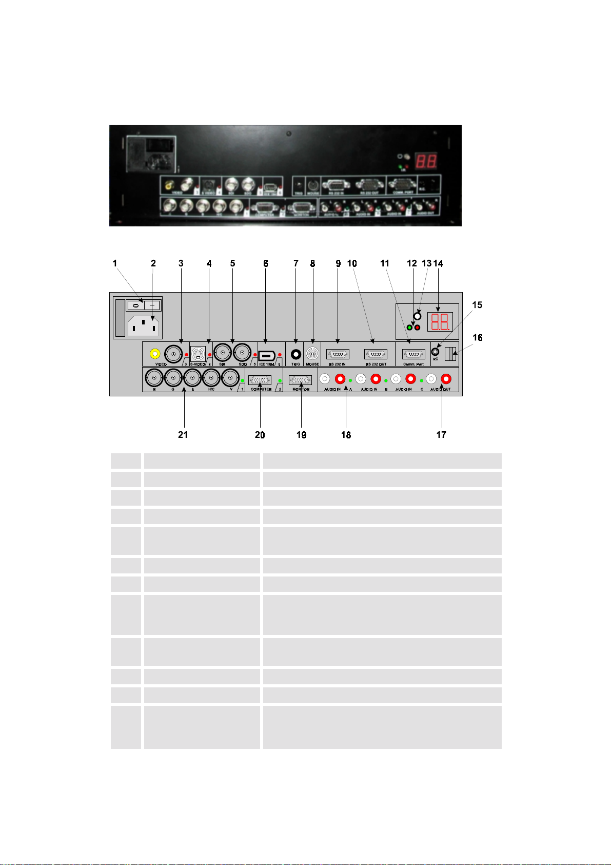
4.1 Control Unit....................................................................................................................... 4-2
4.1.1 Power, source and communication connections [3] .................................................. 4-2
4.2 Control Panel Terminology................................................................................................ 4-4
4.2.1 Local keypad............................................................................................................. 4-4
4.2.2 Remote control.......................................................................................................... 4-4
4.2.3 Terminology of keypad and RCU controls ............................................................... 4-5
5 Connections................................................................................................................................ 5-7
5.1 Power connection............................................................................................................... 5-8
5.1.1 AC Power (mains) cord connection .......................................................................... 5-8
5.1.2 Fuses ......................................................................................................................... 5-8
5.1.3 Switching on ............................................................................................................. 5-8
5.1.4 Image projection ....................................................................................................... 5-8
5.1.5 Lamp Run Time ........................................................................................................ 5-9
5.1.6 Switching to Stand-by............................................................................................... 5-9
5.1.7 Switching Off............................................................................................................ 5-9
5.1.8 Input Connections ................................................................................................... 5-10
5.1.9 Set up of the input selection:................................................................................... 5-10
5.1.10 5-cable Input Slot (slot 1)...................................................................................... 5-11
5.1.11 Computer input/Monitor output ............................................................................ 5-12
5.1.12 Video Input ........................................................................................................... 5-13
5.1.13 S-Video Input........................................................................................................ 5-13
5.1.14 Serial Digital Input / Serial Digital Output............................................................ 5-13
5.1.15 IEEE 1394 Input.................................................................................................... 5-13
Page 6

5.1.16 Communication Connections................................................................................ 5-14
5.1.17 RS232 in / RS232 out............................................................................................ 5-14
5.1.18 Communication port for communication with peripherals.................................... 5-14
5.1.19 TRIG Output ......................................................................................................... 5-15
5.1.20 MOUSE................................................................................................................. 5-15
5.1.21 Audio Connections................................................................................................ 5-15
6 Controlling ............................................................................................................................... 6-16
6.1 RCU used in a hardwired configuration .......................................................................... 6-17
6.2 How to use the RCU? ...................................................................................................... 6-18
6.3 Projector address.............................................................................................................. 6-19
6.3.1 Using the RCU........................................................................................................ 6-19
6.3.2 Displaying a Projector Address............................................................................... 6-19
6.3.3 How to Program an Address into the RCU? ........................................................... 6-19
6.3.4 Picture Controls with Direct Access. ...................................................................... 6-19
6.3.5 Sound controls with direct access ........................................................................... 6-20
7 Start Up of the Adjustment Mode...............................................................................................7-1
7.1 Adjustment mode............................................................................................................... 7-2
7.1.1 Password ................................................................................................................... 7-2
8 Random Access Adjustment Mode ............................................................................................ 8-1
8.1 File Service ........................................................................................................................ 8-2
8.1.1 Load File ................................................................................................................... 8-2
8.1.2 Edit File..................................................................................................................... 8-3
8.1.3 Rename...................................................................................................................... 8-6
8.1.4 Copy.......................................................................................................................... 8-6
8.1.5 Delete ........................................................................................................................ 8-7
8.1.6 File Options............................................................................................................... 8-7
8.2 Picture Tuning ................................................................................................................... 8-8
8.2.1 CTI ON/OFF............................................................................................................. 8-8
8.2.2 Color Temperature .................................................................................................... 8-8
8.2.3 Gamma...................................................................................................................... 8-9
8.2.4 Decoding EBU/IRE................................................................................................... 8-9
8.2.5 Dynamic Color Depth ............................................................................................... 8-9
8.2.6 Noise Reduction........................................................................................................ 8-9
8.2.7 Input Balance .......................................................................................................... 8-10
8.2.8 Audio Tuning .......................................................................................................... 8-10
8.2.9 Volume, Balance, Bass and Treble ......................................................................... 8-10
8.2.10 Mute ...................................................................................................................... 8-11
8.2.11 Fade....................................................................................................................... 8-11
8.2.12 Mode [stereo]/[mono] ........................................................................................... 8-11
8.2.13 Video - Audio lock................................................................................................ 8-11
8.3 Geometry ......................................................................................................................... 8-12
8.3.1 Shift......................................................................................................................... 8-12
8.3.2 Size.......................................................................................................................... 8-12
8.3.3 Blanking..................................................................................................................8-13
8.3.4 Aspect Ratio [5:4]/[4:3]/[16:9]................................................................................ 8-13
8.3.5 Options.................................................................................................................... 8-13
Page 7

9 Installation Mode........................................................................................................................ 9-1
9.1 Input Slots.......................................................................................................................... 9-2
9.2 800 Peripheral.................................................................................................................... 9-3
9.3 Configuration..................................................................................................................... 9-4
9.4 OSD color (On-Screen Display) ........................................................................................ 9-5
9.5 Internal Patterns................................................................................................................. 9-6
9.6 No Signal ........................................................................................................................... 9-7
10 Service Mode.......................................................................................................................... 10-1
10.1 Identification.................................................................................................................. 10-2
10.2 Change Password........................................................................................................... 10-3
10.3 Change Language .......................................................................................................... 10-4
10.4 Change Projector Address.............................................................................................. 10-5
10.5 Change Baudrate PC...................................................................................................... 10-6
10.6 Reset Lamp Runtime ..................................................................................................... 10-7
10.7 BARCO logo ................................................................................................................. 10-8
10.8 Uniformity ..................................................................................................................... 10-9
10.9 Preset Input Balance .................................................................................................... 10-10
10.10 I2C Diagnosis. ........................................................................................................... 10-11
11 Maintenance and Servicing .................................................................................................... 11-1
11.1 Cleaning of Screen......................................................................................................... 11-2
11.1.1 General.................................................................................................................. 11-2
11.1.2 Cleaning the Screen............................................................................................... 11-2
11.2 Replacing ....................................................................................................................... 11-3
11.2.1 Replacing the Lamp Module................................................................................. 11-4
11.2.2 Replacing the Filter Pad........................................................................................ 11-6
12 Technical Data........................................................................................................................ 12-1
12.1 General Data .................................................................................................................. 12-2
12.2 Technical Data of Optical System ................................................................................. 12-3
12.3 Technical Data Of Electrical System............................................................................. 12-4
12.4 Interfaces........................................................................................................................ 12-5
12.4.1 24V Interface......................................................................................................... 12-5
12.4.2 Slot 1: 5 cable input, 5×BNC ................................................................................ 12-5
12.4.3 Slot 2: Computer input/Monitor output................................................................. 12-6
12.4.4 Slot 3: Video Input................................................................................................ 12-6
12.4.5 Slot 4: S-Video Input ............................................................................................ 12-6
12.4.6 Slot 5: Serial digital Input / Serial digital Output.................................................. 12-7
12.5 Parts List ........................................................................................................................ 12-8
12.5.1 Optional Parts........................................................................................................ 12-8
12.5.2 User’s Manuals...................................................................................................... 12-8
12.6 Addresses....................................................................................................................... 12-9
Page 8

13 Configuring Notes .................................................................................................................. 13-1
13.1 Floor Space And Maintenance Area.............................................................................. 13-2
13.2 Overall Height................................................................................................................ 13-4
13.3 Viewing Distance and Angle ......................................................................................... 13-6
13.4 Room Ventilation........................................................................................................... 13-8
14 Troubleshooting...................................................................................................................... 14-1
14.1 Faults ............................................................................................................................. 14-2
14.2 Contact........................................................................................................................... 14-3
14.2.1 Hot Line ................................................................................................................ 14-3
15 Appendix A: Standard Source Set Up Files ........................................................................... 15-1
16 Appendix B: Source Numbers 81 - 86 And 91 - 96 ............................................................... 16-4
16.1 Projector without any 800 peripheral connected............................................................ 16-5
16.2 Projector with a 800 peripheral connected..................................................................... 16-6
16.2.1 Source numbers 91 - 99......................................................................................... 16-6
16.2.2 Source numbers 81 - 86......................................................................................... 16-6
Page 9

1 Introduction
The wide variety of new possibilities to combine different projector and interface technologies to
create customer specific Atlas Display Walls has lead to the creation of a new and more concise
nomenclature. The brand A
Rooms. The single variants on projection units differing in projection technology are expanded by
a mnemonic expression, e. g.:
TLAS
A
67 CS4 Projection unit with Poly-Silicon LCD technology and 67 inch screen
TLAS
A
84 CS4 Projection unit with Poly-Silicon LCD technology and 84 inch screen
This manual describes design, function, operation and maintenance of the large screen rear projection system A
TLAS
A
TLAS
67 CS4 and A
CS4 allows you to display a wide variety of common video and RGB sources. The display
can be controlled via an IR remote control or via an integrated keypad.
TLAS
remains as a generic term for Display Walls from Barco Control
diagonal, SXGA (screen ratio: 5 by 4)
diagonal, SXGA (screen ratio: 5 by 4)
TLAS
84 CS4 of Barco Control Rooms.
R5976255
ATLAS
CS4 (2001-03) 1-1
Page 10

1.1 The A
TLAS
CS4 series
This User’s Manual refers to the models from the A
operation and properties of A
TLAS
A
CS4 refers to both of them. If A
TLAS
67 CS4 and of A
TLAS
there are differences in operation or properties.
1.1.1 Resolution
TLAS
A
CS4 is available with SXGA resolution:
TLAS
A
67 CS4 projection module, 67 inch, SXGA (1280×1024 pixels)
TLAS
A
84 CS4 projection module, 84 inch, SXGA (1280×1024 pixels)
TLAS
TLAS
67 CS4 or A
67 CS4 and A
TLAS
84 CS4 series. Since
84 CS4 are quite similar, the expression
TLAS
84 CS4 are mentioned explicitly,
R5976255
ATLAS
CS4 (2001-03) 1-2
Page 11

1.2 How This Manual Is Organized
This manual is divided into sixteen chapters:
!
Preliminary Remarks
explains the structure of the manual itself and the used typographic styles and symbols. Safety
information is provided concerning the operation of systems from BARCO.
!
Summary
provides a summary of the system components and characteristics.
!
Design and Functions
provides a technical description of the equipment listing the fundamental characteristics and
functional principles. Knowledge of this section is not absolutely essential for operation.
!
Location and Functions of Control
describes the functions and explains the control panel terminology
!
Connections
describes the interfaces of ATLAS CS4
!
Controlling
explains how ATLAS CS4 is operated via the Remote Control Unit and the local keypad
!
Start Up of the Adjustment Mode
explains how to use the menu controlled software of ATLAS CS4
!
Random Access Adjustment Mode
provides an overview of the commands of ATLAS CS4
!
Installation Mode
describes the possible configurations of ATLAS CS4
!
Service Mode
explains the commands which are available in Service Mode
!
Maintenance and Servicing
explains how the equipment can be serviced
!
Technical Data
provides tabular overviews about the technical details of ATLAS CS4.
!
Configuring Notes
provides the mounting dimensions and shows anthropotechnical requirements
!
Troubleshooting
lists possible errors together with steps to eliminate the respective fault.
!
Appendix A: Standard Source Set Up Files
lists all the available set up files for the various timings
!
Appendix B: Source Numbers 81-85 AND 91-96
explains the relationship between source input, source number and set up file
Chapters, pages, figures and tables are numbered separately. Chapters are indicated by a »point
syntax«, e. g.
, pages by a »dash syntax«, e. g.
4.2.3
, as figures and tables are, e. g.
2-1
Figure 5-4
.
R5976255
ATLAS
CS4 (2001-03) 1-3
Page 12
1.3 Styles And Symbols
The typographic styles and the symbols used in this document have the following meaning:
Helvetica bold
Labels, menus and buttons are printed in the
Condensed
Helvetica bold
Links to both other chapters of this manual and to sites in the Internet are printed
on-line version of this manual all hyperlinks appear
teal
font.
condensed
.
Courier
Names of files and parts from programs are printed in the Courier font.
Courier bold
Inputs you are supposed to do from the keyboard are printed in Courier bold font.
. In the
!
Within a piece of progr am m ing code this arrow marks a li ne, that must be made up
in two lines, though meant to be one line.
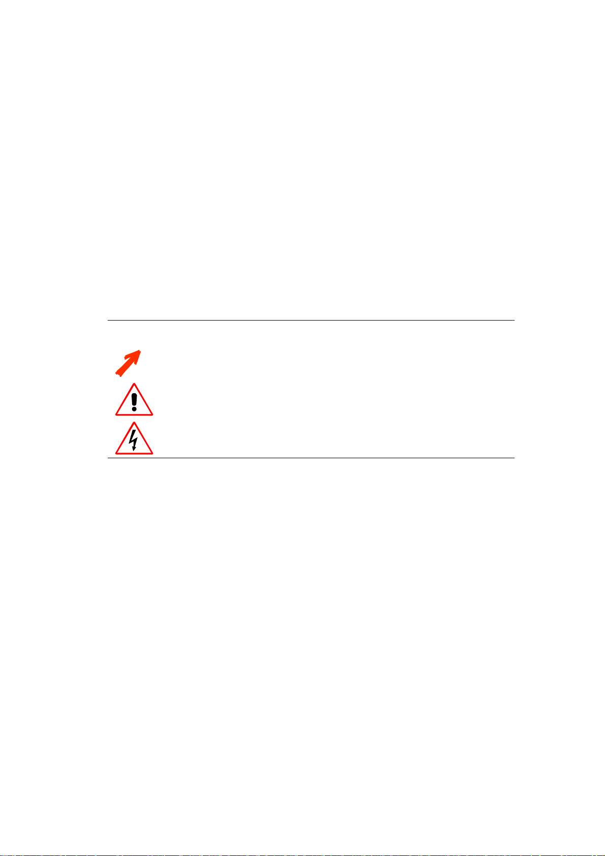
This arrow marks tips and notes.
If you do not heed instructi ons indicated by this symbol there is a risk of damage to
the equipment!
If you do not heed instructions indicated by this s ymb ol there is a risk of electrical
shock and danger to personal health!
R5976255
ATLAS
CS4 (2001-03) 1-4
Page 13
1.4 Safety Information
This section describes safety precautions which must be observed when installing a product from
BARCO.
Safetey
The safety standards of information technology equipment impose important requirements on the
use of safety critical components, materials and isolation, in order to protect the user or operator
against the risk of electric shock and energy hazard, and having access to live parts.
Safety standards also impose limits to the internal and external temperature rises, radiation levels,
mechanical stability and strength, enclosure construction and protection against risk of fire.
Simulated single fault condition testing ensures the safety of the equipment to the use even when
the equipment’s normal operation fails.
General safety instructions
! All the safety and operating instructions should be read before using this unit.
! The operating instructions manual should be retained for future reference.
! All warnings on the device and in the documentation manuals should be adhered to.
! All instructions for operating and use of this equipment must be followed precisely.
Installation and Service
Installation and preliminary adjustments should be performed by qualified BARCO personnel or
authorized BARCO service dealers.
On Safety
Check the power rating on your outlet before connecting the devices to the wall
outlet or to a power strip. Contact your facilities manager or a qualified electrician if
you are not sure what type of pow er is supplied to your building.
The devices are designed to operate with single-phase power systems having a
grounded neutral conduct or. To reduce the risk of electrical shock, do not plug i n to
any other type of power system.
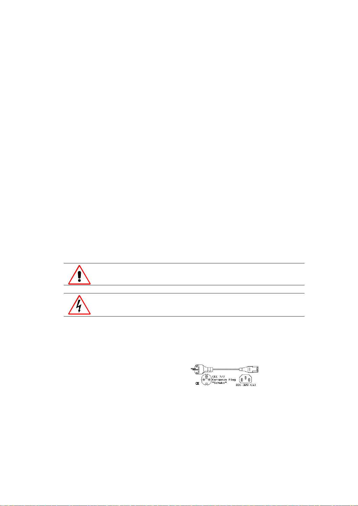
A. Mains lead (AC Power cord) with CEE 7 plug:
The colors of the mains lead are colored in accordance with the following code:
Green-and-yellow: Earth (safety earth)
Blue: Neutral
Brown: Line (live)
R5976255
ATLAS
CS4 (2001-03) 1-5
Page 14
B. Power cord with ANSI 73.11 plug:
The wires of the power cord are colored in accordance with the following code:
Green/yellow: Ground
White: Neutral
Black: Line (live)
! Do not allow anything to rest on the power cord. Do not locate this product where persons will
walk on the cord.
! To disconnect the cord, pull it out by the plug. Never pull the cord itself.
! If an extension cord is used with this product, make sure that the total of the ampere ratings on
the products plugged into the extension cord does not exceed the extension cord ampere rating.
Also make sure that the total of all products plugged into the wall outlet does not exceed 15
amperes.
! Never push objects of any kind into this product through cabinet slots as they may touch dan-
gerous voltage points or short out parts that could result in a risk of fire or electrical shock.
! Never spill liquid of any kind on the product. Should any liquid or solid object fall into the
cabinet, unplug the set and have it checked by qualified service personnel before resuming operations.
Warning: Do Not Place Flammable or Combustible Materials Near Projector!
BARCO products are designed and manufactured to meet the most stringent safety regulations.
Exposing flammable or combustible materials into close proximity of this device could result in
the spontaneous ignition of that material, resulting in a fire. For this reason, it is absolutely necessary to leave an "exclusion zone" around all external surfaces of the projector whereby no flammable or combustible materials are present. The exclusion zone must be not less than 10 cm (4").
Do not cover the projector with any material while the projector is in operation.
Keep flammable and combustible materials away from the projector at all times. Mount the projector in a well ventilated area away from sources of ignition and out of direct sun light. Never expose this product to rain or excessive moisture. In the event of fire, use sand, CO
, or dry powder
2
fire extinguishers; never use water on an electrical fire.
Always have service performed on this product by authorized BARCO service personnel. Always
insist on genuine BARCO replacement parts. Never use non-BARCO replacement parts as they
may degrade the safety of this device.
Use only the power cord supplied with your device. While appearing to be similar, other power
cords have not been safety tested at the factory and may not be used to power the projector. For a
replacement power cord, contact your dealer.
Slots and openings in the cabinet and the sides are provided for ventilation; to ensure reliable operation of the device and to protect it from overheating, these openings must not be blocked or
covered. This product should never be placed near or over a radiator or heat register. This product
should not be placed in a built-in installation or enclosure unless proper ventilation is provided.
R5976255
ATLAS
CS4 (2001-03) 1-6
Page 15

On Servicing
Do not attempt to service this device yourself, as opening or removing covers may expose you to
dangerous voltage potential and risk of electric shock! Refer all projector service to a qualified
BARCO service center.
Adjust only those controls that are covered by the operating instructions since improper adjustment of the other controls may result in damage and will often require extensive work by a qualified technician to restore the product to normal operation.
Call for service in the following conditions :
! When the power cord or plug is damaged or frayed.
! If liquid has been spilled into the device.
! If the product has been exposed to rain or water.
! If the product does not operate normally when the operating instructions are followed.
! If the product has been dropped or the cabinet has been damaged;
! If the product exhibits a distinct change in performance, indicating a need for service.
When replacement parts are required, be sure the service technician has used original BARCO replacement parts or authorized replacement parts which have the same characteristics as the
BARCO original part. Unauthorized substitutions may result in degraded performance and reliability, fire, electric shock or other hazards. Unauthorized substitutions may void warranty.
Upon completion of any service or repairs to this unit, ask the service technician to perform safety
checks to determine that the unit is in proper operating condition.
1.4.1 Precautions
For your own protection, observe the following safety precautions when installing your device!
! Observe all warnings and instructions printed on the devices!
! Check that the voltage and frequency of your power supply match those printed on the device
label with the rated electrical values!
! Servicing not explicitly mentioned in this manual should never be carried out by unauthorized
personnel!
1.4.2 Unpacking of Devices
Note advises on the packaging for unpacking!
1.4.3 Modification of Devices
Mechanical or electrical modifications others than described in this manual must not be made to
the devices. BARCO is not liable for damages resulting from modified devices.
Only authorized personnel should carry out other mai ntenance work not explicitly
mentioned in this user's man ual!
Never open the case of the power supply or of the projection unit without first disconnecting the power supply cord! Measurements and tests with an opened device
may be carried out only in the factory or by specially tr ained personnel, due to the
dangers of electri cal shock.
R5976255
ATLAS
CS4 (2001-03) 1-7
Page 16

2 Abbreviated Summary
This chapter provides a summary of the system components and characteristics.
R5976255
ATLAS
CS4 (2001-03)
2-1
Page 17
2.1 Design
TLAS
CS4 is a modular rear projection system for the construction of large Display Walls. The
A
technologies used guarantee the best optical properties for high-quality presentation of information
with very simple integration into higher-level systems.
Technology
TLAS
A
CS4 combines the latest modern projection technology with sophisticated electronics and
solid mechanics. This design results in high image quality and reliability.
Application Fields
TLAS
A
CS4 can be used wherever a large-area presentation of computer data or video is required.
It is designed for continuous operation (24h).
High-quality and large-area displaying of monitor contents is becoming increasingly important
Simple data presentations are being increasingly supplemented by multimedia applications with
video displays. A
TLAS
A
CS4 is multimedia-compatible since it can be connected to any current source (digital and
TLAS
CS4 provides optimum solutions which also satisfy the highest demands.
analog camcorder sources, analog video tape sources, DVD, Laserdisc, digital video tape sources,
computer data sources). Audio reproduction is possible by connecting amplifiers or active boxes to
the audio socket. Personal computers with the following graphics adapters can be connected as the
data sources: SXGA, XGA, SVGA, VGA. Workstations, Apple Macintosh and Power Macintosh
are also supported. Remote real-time switching is possible between all sources.
User Friendly
The rear panel of an A
TLAS
CS4 projection cube gives free access to all control elements. The only
maintenance work, i. e. cleaning the dust filter and replacing the lamps, can be done within few
seconds and makes no re-adjustment necessary.
Environmentally Friendly
The burning life of the used 100 Watt lamps is very high at 8000 hours. This long lamp lifetime
and the low power consumption do not only reduce the cost of ownership but also contribute to
saving energy and natural resources.
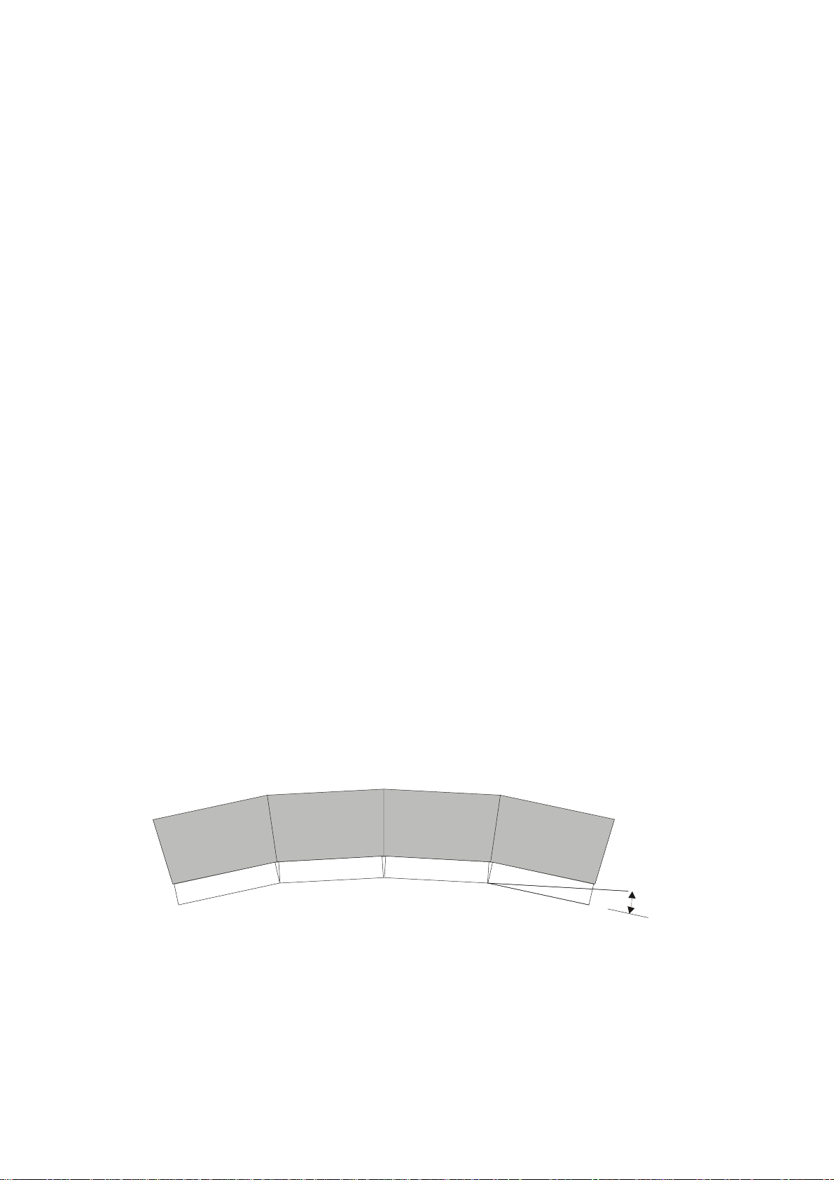
Flexible Configuration
A
TLAS
CS4 D
ISPLAY WALLS
consists of a modular aluminum structure on which mechanical and
optical components are fixed. This makes it possible to build curved display walls with any size of
screen.
0° to 8°
Curved Display Wall consisting of 4 Atlas CS4 Units
Figure 2-1
R5976255
ATLAS
CS4 (2001-03)
2-2
Page 18

2.2 Properties of A
TLAS
CS4
ATLAS CS4 can be used as one large monitor with a screen diagonal of 67 or 84 inches. The
technologies used guarantee the best optical properties for high-quality presentation of both computer data and video displays:
!
High, Constant Reading Accuracy Over the Complete Display Panel
Optimally adjusted high-performance lens systems guarantee a distortion-free and sharp image.
!
Bright Displays
A 100W UHP™ lamp provides a high luminous flux which is passed on at great efficiency by
the illumination system.
!
High Contrast
The screen has a surface which absorbs ambient light falling on it and increases the contrast.
!
Easy Adjustment and Low-maintenance
Readjustment of the components is not required. The operation time of the lamps is very high
at 8000 hours. Lamp and filters can be replaced without special training from the front.
!
Ready for any applicati o n
The source is automatically recognized. The projector has intelligent and user-adjustable priority switching.
R5976255
ATLAS
CS4 (2001-03)
2-3
Page 19

3 Design and Function
This chapter provides a technical description of the equipment listing the fundamental characteristics and functional principles. Knowledge of this section is not absolutely essential for operation.
R5976255
ATLAS
CS4 (2001-03)
3-1
Page 20
3.1 Projection Unit
Atlas 67 CS4
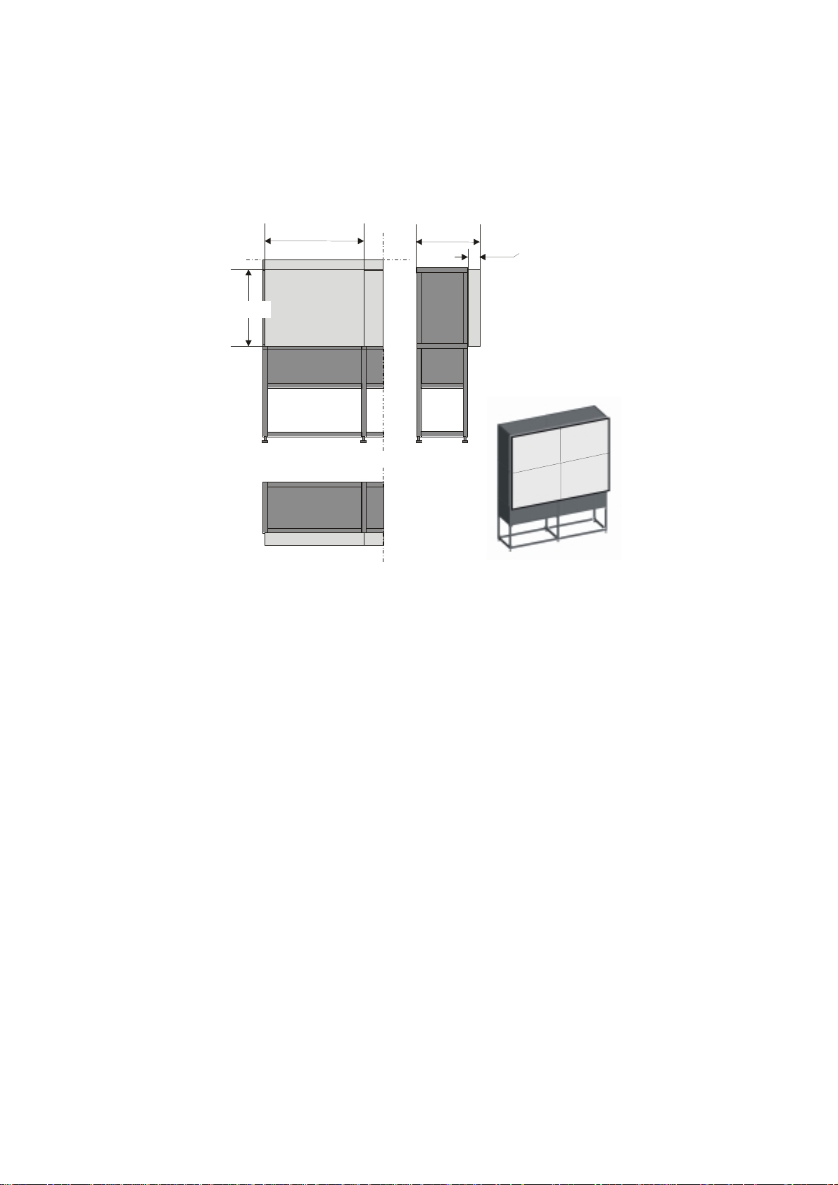
The Atlas 67 CS4 Unit has a display area of 1068 millimeters high and 1335 millimeters wide. The
resulting screen diagonal of 1710 millimeters corresponds to approximately 67 inches.
1068
1335
930,6
132
Figure 3-1
Atlas 67 CS4 Unit
R5976255
ATLAS
CS4 (2001-03)
3-2
Page 21
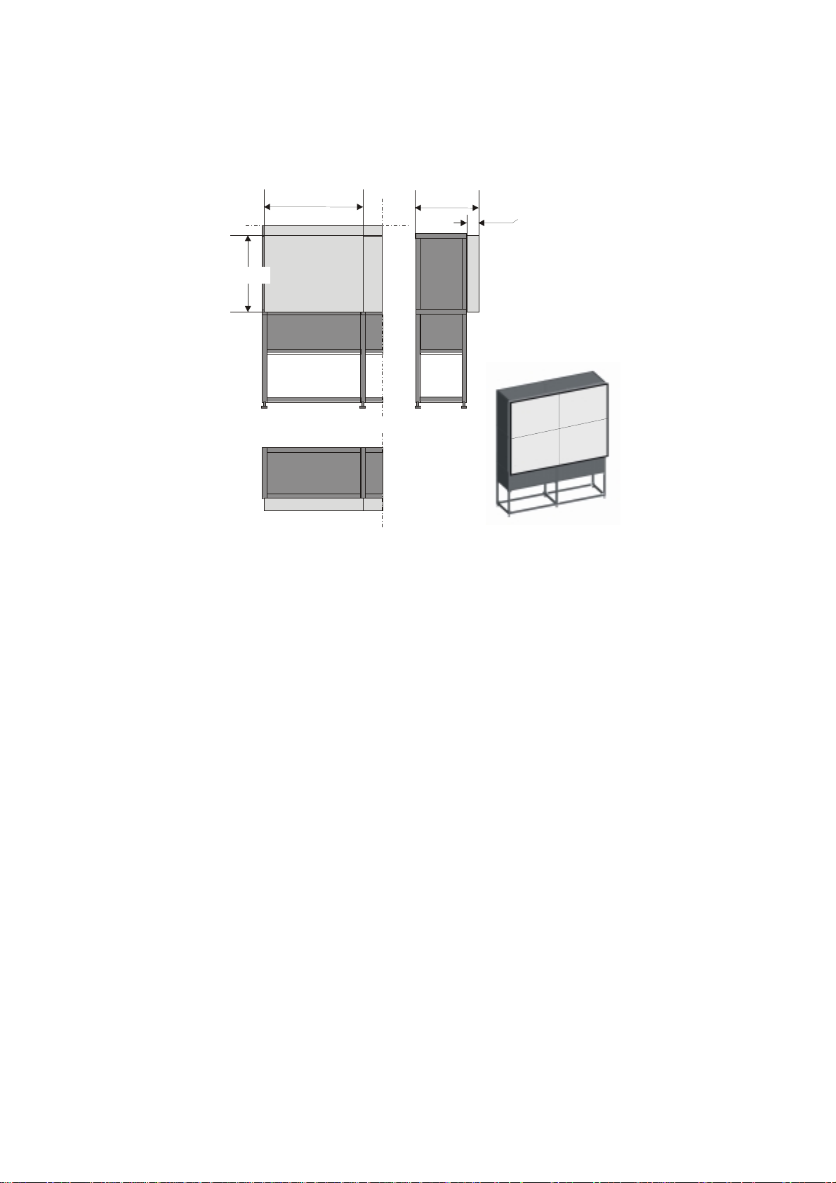
Atlas 84 CS4
The Atlas 84 CS4 Unit has a display area of 1320 millimeters high and 1650 millimeters wide. The
resulting screen diagonal of 2113 millimeters corresponds to approximately 84 inches.
1320
1650
1212
132
Figure 3-2
Atlas 84 CS4 Unit
R5976255
ATLAS
CS4 (2001-03)
3-3
Page 22
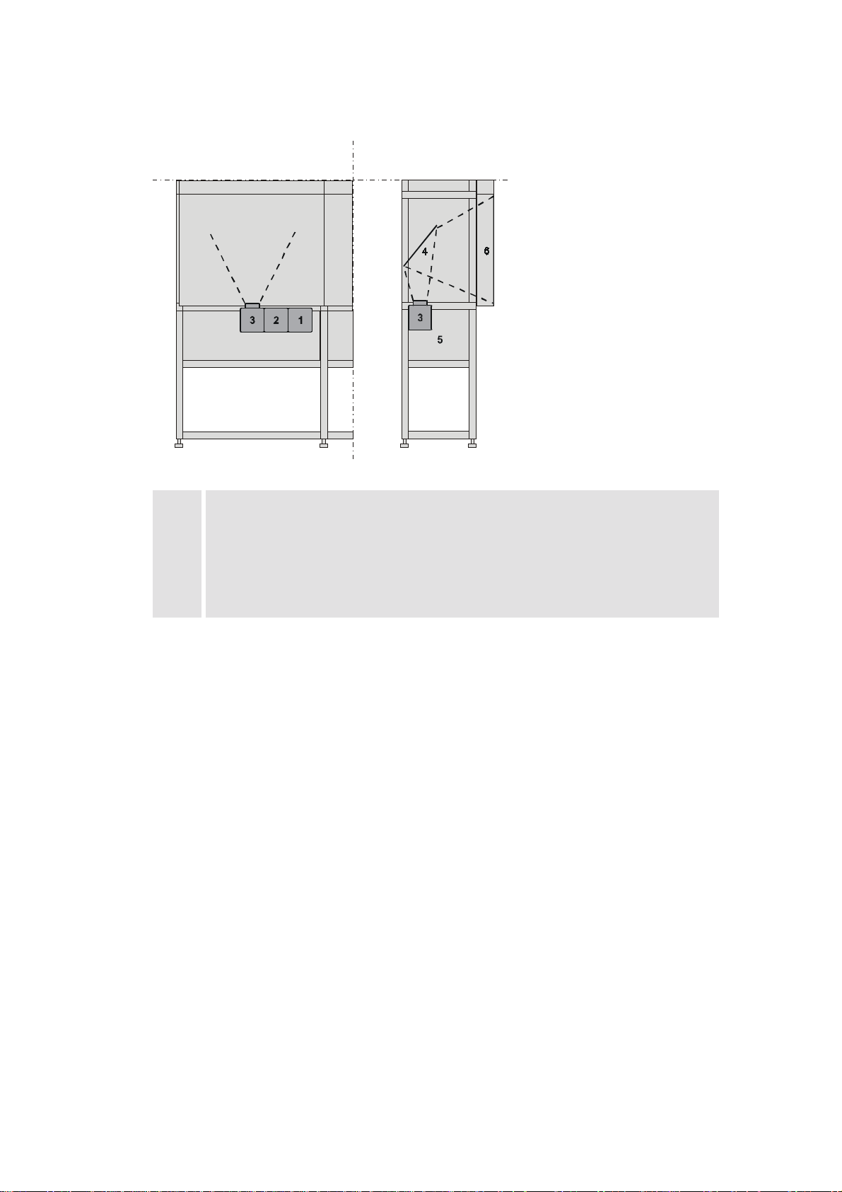
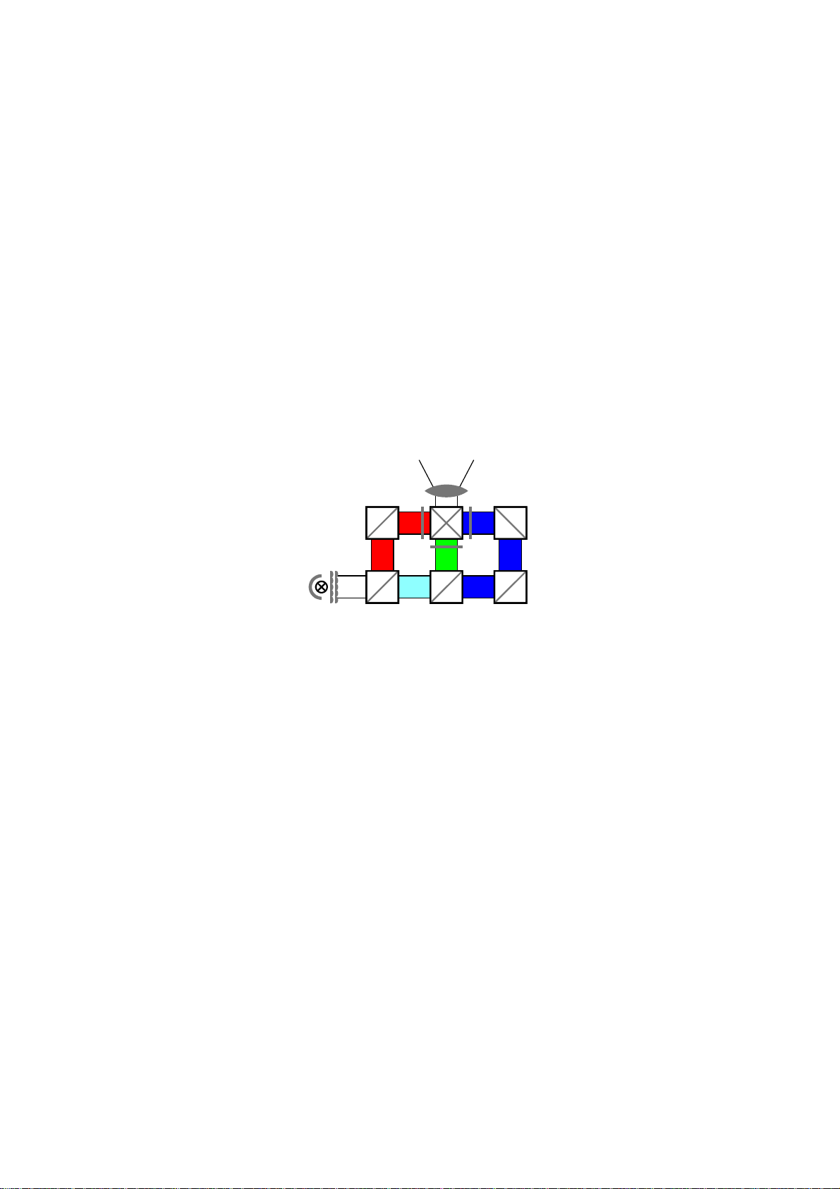
The Atlas CS4 projection modules consists of the following components:
1
2
3
4
5
6
lamp module
illumination unit
projection unit
deflection mirror
Atlas structure covered with light shields
screen
Figure 3-3
! Housing: The Atlas system is a compact mechanical housing especially designed to meet any
given requirements concerning set up, resolution, and operational conditions. Due to its flexible structure different projector types and screens can be mounted. The closed structure prevents incident light or dust from entering the unit.
! Projection unit: The projection unit consists of three components: the lamp module, the light
path for optimization of the light distribution and the X Cube and dichroic prism system.
! Deflection mirror: a mirror in the top part of the housing deflects the light onto the rear of the
projection screen.
! Screen: patented seamless screen mounting via high precision cuts, supported by very fine steel
pins results in a nearly not perceptible optical seam.
! Fan: a fan in the housing ensures that the unit is sufficiently cooled.
R5976255
ATLAS
CS4 (2001-03)
3-4
Page 23
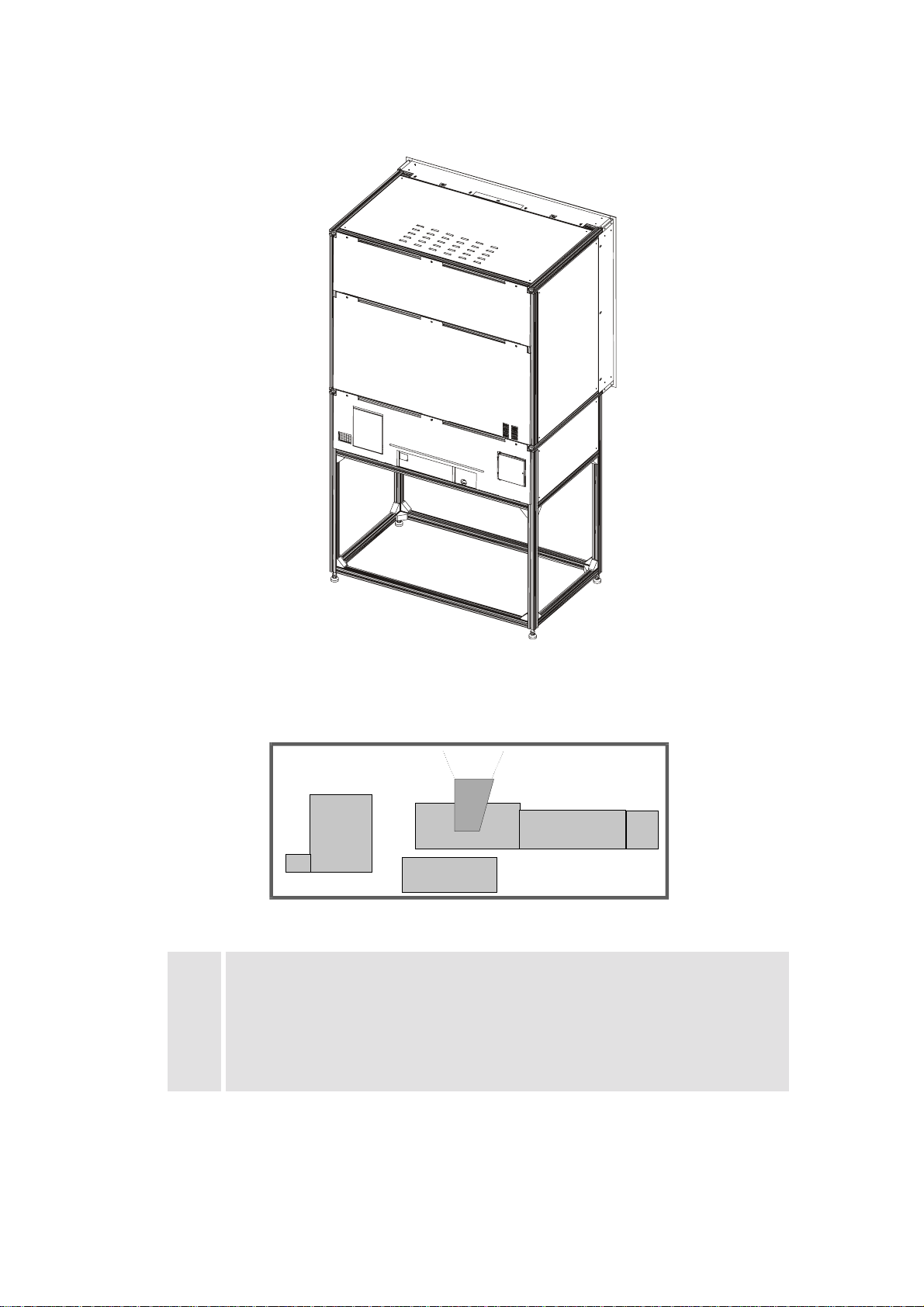
TLAS
A
CS4 has been designed for rear access of interfaces and exchange of consumables (lamp
module, filters..).
1
2
3
rear side of Atlas CS4
4
21
3
65
Figure 3-4
rear side of Atlas CS4 (schematic)
1
2
3
4
5
6
keypad
filter pad
control unit
projection unit
illumination unit
lamp module
Figure 3-5
R5976255
ATLAS
CS4 (2001-03)
3-5
Page 24
3.1.1 Lamp Module
r
The lamp module generates the light for the subsequent projection. The lamp (100 Watt UHP (Ultra High Performance) lamp) has an operation time of 8000 hours.
3.1.2 Illumination Unit
The illumination unit consists of the lens system for uniform illumination of the LCDs and the
electronics for lamp power supply and monitoring.
!
Optical Integrator
An optical integrator consisting out of two multi-segment lenses guarantees a uniform illumination of the LCDs and thus of the screen.
3.1.3 Projection Unit
The light from the lamp is split with dichroic mirrors into red, green and blue light to illuminate
three LCD panels, each of which contains the respective color-information for the red, green and
blue parts of the projected image. The LCD panels are attached to a cubical prism called X Cube
which recombines the three light paths, so the image is projected using a single lens.
Lens
X Cube
Mirro
LCDs
Lamp
Integrator
3-panel Poly-Silicion LCD
!
Poly-Silicon TFT-LCD
The LCD panels are based on Poly-Silicon technology. Poly-Silicon material consists of numerous small crystals leading to small circuitry. The results are a big aperture (ratio of a pixel’s
shutter area to it’s total area), high speed and reliability. The panels have 1,310,720 (SXGA
1280×1024) pixels.
!
Lens System
The projection lens system is positioned behind the X Cube. It projects the image resulting on
the LCD’s via the deflection mirror onto the rear of the screen module.
Figure 3-2
R5976255
ATLAS
CS4 (2001-03)
3-6
Page 25

3.1.4 Screen Module
The image is generated in the screen . It consists of the optical screen and a frame with which the
screen is exactly mounted onto the Atlas Structure.
!
Fresnel Lens
The screen consists of a Fresnel lens and a Front Element Screen. The Fresnel lens deflects the
light coming from the projection lens system such that it falls perpendicularly onto the front
element screen.
!
Front Element
The front element screen guarantuees that the light is distributed horizontally and vertically,
while maintaining a high contrast.
!
Texture of Surface
The surface of the screen has a special non-glare texture. This texture minimizes the direct reflection of the light of the surrounding and contributes also to the high contrast of the screen.
R5976255
ATLAS
CS4 (2001-03)
3-7
Page 26

4 Location and Functions of Co ntrol
This chapter provides an overview about the controls of A
TLAS
CS4.
R5976255
ATLAS
CS4 (2001-03)
4-1
Page 27
4.1 Control Unit
4.1.1 Power, source and communication connections [3]
1 Power switch 1 = on, 0 = off
2 Power input autoranging from 100VAC to 240VAC
3 Video input 1 cinch or 1 BNC connector, no loop through
4 S-Video 4-pin mini-DIN
5 SDI and SDO 2× BNC terminals, serial digital input and loop through
output
6 IEE 13994 not yet implemented
7 TRIG (mini-jack) output voltage of 5V when projector is on
8 Mouse (DIN 13) mouse output to be connected to the mouse
input of a computer. The computer can now be controlled via the Executive Remote Control Unit
9 RS232 IN (D9), to allow communication with external computer,
e. g. IBM PC or compatible, MAC ..
10 RS232 OUT (D9), used to connect to next projector, RS232 IN plug
11 Communication port (D9), allows communication with the 800 peripherals
12 IR-Acknowledged
IR-Received
IR-Signals are recognized
IR-Signals are received but not recognized by the projector
R5976255
ATLAS
CS4 (2001-03)
4-2
Page 28

13 Projector mode indication indicates the status of the projector
Light off: power switch is not pressed
Red light: power switch is pressed, projector in
standby mode
Green light: projector in operational mode
14 Diagnostics code a) source number
b) error code: a two digit error code is displayed
15 Remote (mini-jack), remote input for wired remote control
16 IR-receiver Receiver for control signals transmitted from the RCU
17 Audio output
18 Audio input 3 audio inputs. Each audio input can be associated with
arbitrary input
19 Monitor output the monitor of your computer can be connected to this
output if your computer is connected to the computer
input
20 Computer input
21 5-cable input can be software switched between Video, S-Video,
RGB analog or Component Video
R5976255
ATLAS
CS4 (2001-03)
4-3
Page 29
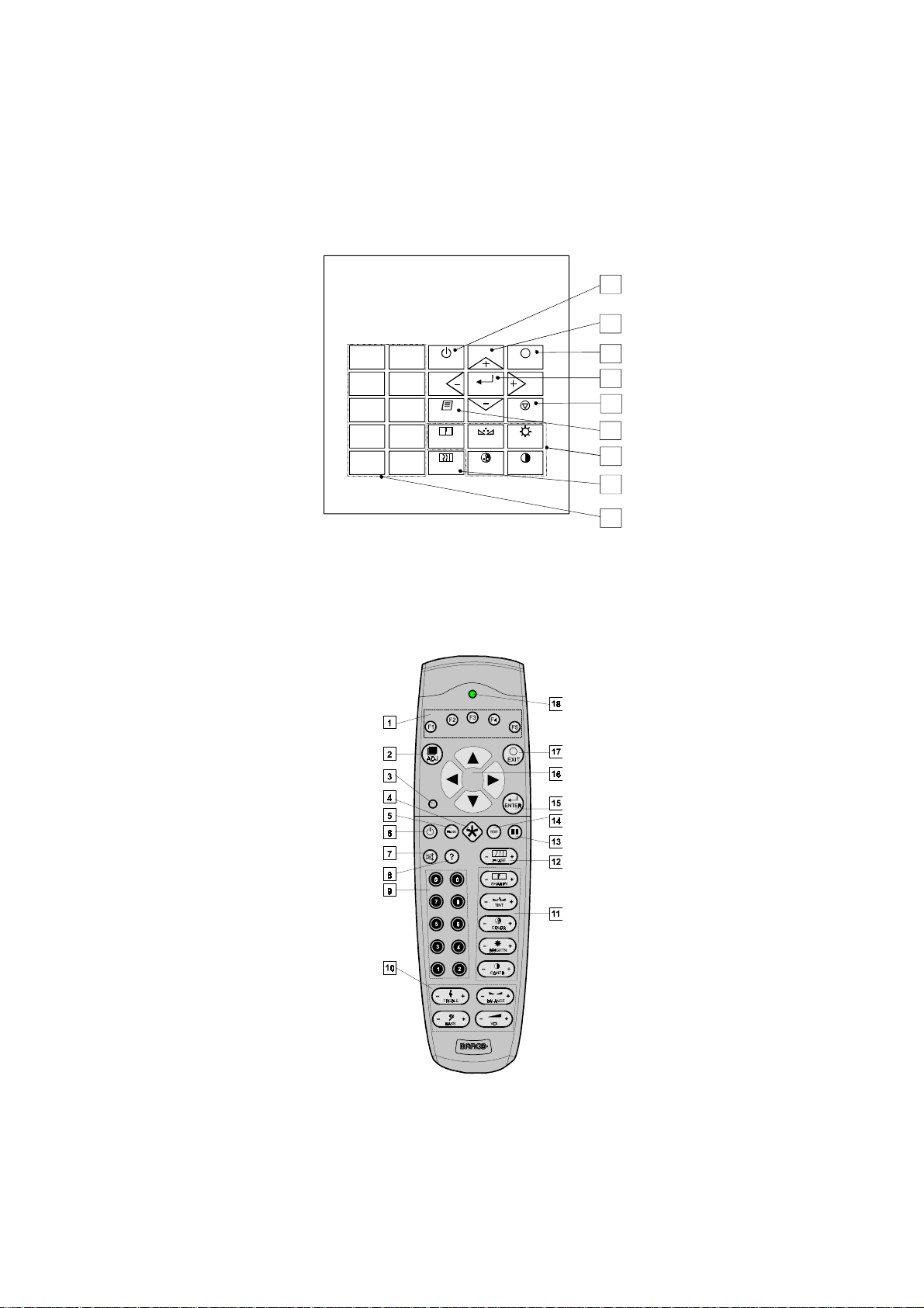
4.2 Control Panel Terminology
The projector can be controlled by the local
4.2.1 Local keypad
The local
(explanation see
[1] is located on the back side of the A
keypad
4.2.3 Terminology of keypad and RCU controls
or by the remote control unit (
keypad
TLAS
CS4
)
16
)
RCU
6
4.2.2 Remote control
This remote control unit (
RCU
user to control the projector remotely.
0
9
7
5
3
1
STANDBY
8
6
TEXT
4
SHARPN
2
PHASE
ENTER
TINT
COLOR
EXIT
PAUSE
BRIGHTN
CONTRAST
17
15
5
14
11
12
9
Figure 4-1
The local keypad
) includes a battery powered infrared (IR) transmitter that allows the
R5976255
ATLAS
CS4 (2001-03)
IR Remote Control Unit (RCU)
Figure 4-2
4-4
Page 30

This remote control is used for source selection, control, adaptation and set up. It includes automatic storing of the picture controls (brightness, sharpness ...) and the settings.
Other functions of the remote control are:
! switching between standby and operational mode
! switching to "pause" (blank picture, full power for immediate restarting)
! direct access to all connected sources.
4.2.3 Terminology of keypad and RCU controls
1 Function keys have no function for this projector
2 ADJ ADJUST key, to enter or exit the adjustment mode.
3 Address key (recessed key), to enter the address of the projector (between 0 and
9). Press the recessed address key with a pencil, followed by pressing one digit button between 0 and 9.
4 Selection key to direct access the zoom/focus/shift functions.
5 PAUSE to stop projection for a short time, press 'PAUSE'. The image disap-
pears but full power is retained for immediate restarting.
6 Standby stand by button, to start projector when the power switch is switched
on and to switch off the projector without switching off the power
switch.
Attention : Switching to Stand-by.
When the projector is running and you want to go to stand-by, press
the stand-by key for 2 seconds until the message 'Saving data, please
wait' is displayed. Do not press any longer on the stand-by key
otherwise the projector will restart.
7 Mute to interrupt the sound reproduction.
8 Help on line help information (not yet available)
9 Digit buttons direct input selection.
10 Audio controls use these buttons to obtain the desired sound level
11 Picture controls use these buttons to obtain the desired picture analog level
12 PHASE used to remove the instability of the image.
13 Freeze press to freeze the projected image.
14 TEXT when adjusting one of the image, e.g. controls during a meeting, the
displayed bar scale can be removed by pressing 'TEXT' key first. To
re-display the bar scale on the screen, press 'TEXT' key again.
15 ENTER to start up the adjustment mode or to confirm an adjustment or se-
lection in the adjustment mode.
R5976255
ATLAS
CS4 (2001-03)
4-5
Page 31

16 Cursor Keys (
) or '' and '-'
RCU
keys (cursor
keys) on the local
keypad
to make menu selections when in the adjustment mode or to
on
zoom/focus when the direct access is active.
Comparison between the cursor keys and the use of the '+' and '-'
keys on the local keypad
RCU local keypad
cursor key up '+' key up
cursor key down '-' key down
cursor key right '+' key right
cursor key left '-' key left
Use the '+' and '-' keys (cursor keys) to increase or decrease the analog level of the image controls when they are first selected.
17 EXIT to leave the adjustment mode or to scroll upwards when in the ad-
justment mode.
18 RC operating
indication
lights up when a button on the remote control is pressed. (This is a
visual indicator to check the operation of the remote control)
R5976255
ATLAS
CS4 (2001-03)
4-6
Page 32

5 Connections
This chapter explains the various interfaces of A
TLAS
CS4.
R5976255
ATLAS
CS4 (2001-03)
5-7
Page 33

5.1 Power connection
5.1.1 AC Power (mains) cord connection
0
I
2
1
34 56
R G B H/C V COMPUTER MONITOR AUDIO IN AUDIO IN AUDIO IN AUDIO OUTABC12
RS 232 IN RS 232 OUT Comm. PortIEE 1394 TRIG MOUSEVIDEO S-VIDEO SDI SDO
RC
! Use the supplied power cord to connect your projector to the wall outlet.
! Plug the female power connector into the male connector [1] at the control panel.
The power input is auto-ranging from 90 to 240 VAC.
5.1.2 Fuses
For continued protection against fire hazard:
- refer replacement to qualified service personnel
- ask to replace with the same type of fuse.
Fuse type : T3.15 AH/250V
5.1.3 Switching on
Use the
switch [2] to switch on. When
power
is visible, the projector is switched off. When
'0'
is visible, the projector is switched on.
When switching on with the
switch, the projector starts in the
power
standby mode
mode indication lamp is red.
'1'
. The projector
5.1.4 Image projection
To start image projection:
! apply the appropriate voltage to the 24V interface. The
green.
! press the
mode indication lamp
'Stand by'
button once on the local keypad or on the remote control. The
will be green.
! press a digit button to select an input source. The
green.
R5976255
ATLAS
CS4 (2001-03)
projector mode indicati on lamp
projector mode indicati on lamp
will be
projector
will be
5-8
Page 34

5.1.5 Lamp Run Time
The operation time of the lamp is 8000 hours. The total hours of operations are counted and can be
displayed on the screen.
The total lifetime of the lamp for a safe operation at high and constant brightness is
about 8000 hours. Always replace with a same type of lamp
5.1.6 Switching to Stand-by
When the projector is running and you want to go to stand-by:
! Press the
STANDBY
Do not press any longer on the
key for 2 seconds until the message
standby
key otherwise the projector will restart.
'Saving data, pleas e wai
t' is displayed.
! Switch off the voltage of the 24V interface.
5.1.7 Switching Off
To switch off:
! Switch off the voltage of the 24V interface or press
message
'Saving data, please wait'
is displayed, do not press any longer on the standby key
STANDBY
key for 2 seconds. When the
otherwise the projector will restart.
! Let cool down the projector at least 10 min.
! Remove the paneling to gain access to the
! Switch off the projector with the
power
switch.
When switching to standby, it is possible to restart within the first 5sec. When not
restarted within these first 5 sec., you have to wait one minute for being able to restart again. During the period when restarting is disabled the LED display will show
a jumping square with a dash. When restarting is enabled again, two dashes will be
displayed to indicate that the projector can be restarted.
power
switch.
R5976255
ATLAS
CS4 (2001-03)
5-9
Page 35

5.1.8 Input Connections
TLAS
A
CS4 has multiple input connections for all common RGB and video sources. The input can
be selected either manually or automatically. When
'automatic'
is selected in the
Input slots menu,
by starting up the projector, it searches for an input source by scanning the inputs one by one. If
only one source is found, this source will be projected. If different sources are found, the priority is
as follows
input facilities priority of automatic input selection
Video 1
S-Video 2
5-cable input 3
Computer 4
Serial digital input never automatically selected
IEEE 1394 (not yet active) never automatically selected
When a RCVDS is connected to the projector, the '
5.1.9 Set up of the input selection:
! Press
! Press the cursor key
! Press
! Press the cursor key
! Press
to start up the adjustment mode.
ENTER
or
up
down
to display the
ENTER
ENTER
to display the
Installation menu
or
up
down
Input slots menu
to select
to select
'Installation'
.
'Input Slots'
.
In the Input slots menu the available input sources are marked with
! Press the cursor key
! Press
! Press
ENTER
EXIT
to toggle between [
several times to leave the adjustment mode.
up
or
down
to select
Manual
'Input Slots'
] or [
Automatic
Use of a RCVDS05 or VS05 :
When using a RCVDS05, it is recommended to use a 5-cable output module in the
RCVDS. The outputs of this module have to be connected to the 5 cable input
(slot 1) of the projector.
To switch the projector in the 5-cable mode see chapter
Automatic
' selection is disabled.
.
.
x
.
].
9 Installation Mode
.
R5976255
ATLAS
CS4 (2001-03)
5-10
Page 36

5.1.10 5-cable Input Slot (slot 1)
Slot 1 has 5 BNC input terminals.
The following signals can be connected to these BNC connectors:
Connector name R G B H V
Input signal
RGBHV R G B H V
RGBS R G B S -
RGsB R Gs B - -
Composite Video - Video - - -
Super Video - Y - - C
Component Video - SS R-Y Y B-Y S -
Component Video - SOY R-Y Ys B-Y - -
Slot 1 selection
To select slot 1:
! Press the digit button
Configuration of the 5-cable input
The configuration has to be done on the
on the RCU or the local keypad.
1
'Input slot'
menu.
To change the signal format:
! Press
ADJUST
or
ENTER
to start up the
Adjustment
mode.
! Push the cursor key
! Press
ENTER
.
! Press the cursor key
! Press
Slots' menu
. The internal system will scan the inputs and displays the result in the
ENTER
.
! Push the cursor key
! Press
key to toggle the input signal priority.
ENTER
up
up
up
or
or
or
to select
down
to select
down
to select the first slot.
down
Installation
'Input Slots'
'Input
R5976255
ATLAS
CS4 (2001-03)
5-11
Page 37

Possible indication:
RGB [HS&VS] RGB analog signals, separate sync is horizontal and vertical
sync.
RGB CS RGB analog signals, separate sync is composite sync.
RGB CV RGB analog signals, separate sync is composite video or tri-
level sync.
RGB-SOG RGB analog signals, sync on green is composite sync.
COMPONENT VIDEO - CS separate sync is composite sync.
COMPONENT VIDEO component video with composite sync on Y or composite tri-
level sync on Y.
VIDEO
S-VIDEO
When using an RCVDS 05 with a 5 cable output module, connect these 5 cables
to this 5-cable input slot (slot1) of the projector.
All sources of the RCVDS can now be accepted by the projector.
5.1.11 Computer input/Monitor output
! Connect the output of the graphical card of the computer to the
computer input
(connection < 60 cm) or insert an interface between the output of the computer and the input of
the projector.
! Connect the monitor of the computer to the monitor output of the projector.
! This monitor output is only available when the computer input is used as input.
Pin configuration of the D15 connector:
1 RED 9 loop through to monitor
2 GREEN 10 ground
3 BLUE 11 loop through to monitor
4 loop through to monitor 12 loop through to monitor
5 ground 13 sync horizontal / composite
6 ground 14 sync vertical
7 ground 15 loop through to monitor
8 ground
Slot 2 selection:
! Press the digit button
on the
2
or the local
RCU
keypad
.
of the projector
R5976255
ATLAS
CS4 (2001-03)
5-12
Page 38

5.1.12 Video Input
Input signal:
Composite video signals from a VCR, OFF air signal decoder, etc...
1 x BNC or cinch 1.0Vpp ± 3 dB
No loop through.
Slot 3 selection:
Press the digit button 3 on the
5.1.13 S-Video Input
or the local
RCU
keypad
.
Input signal:
Separate Y-luma/C-chroma signals for higher quality playback of Super VHS-signals.
Pin configuration mini DIN plug:
1 ground luminance
2 ground chrominance
3 luminance 1.0Vpp ± 3 dB
4 chrominance 282 mVpp ± 3 dB
Slot 4 selection:
Press the digit button 4 on the
or the local
RCU
keypad
.
5.1.14 Serial Digital Input / Serial Digita l Output
Full compatibility with digital Betacam, or digital video sources.
This avoids the need for analog processing anywhere in the video production chain and guarantees
the ultimate image quality.
An active loop through of the SDI input signal is provided for monitoring or for double or triple
stacking applications.
connections:
1 x BNC input and 1 x BNC output.
The input is always 75 Ω terminated. The output impedance of the SDO is 75 Ω.
Slot 5 selection:
Press the digit button 5 on the
or the local
RCU
keypad
.
When a RCVDS05 is connected to the projector, the SDI input is available by keying in 85 on the
5.1.15 IEEE 1394 Input
RCU
.
Input not yet implemented.
R5976255
ATLAS
CS4 (2001-03)
5-13
Page 39

5.1.16 Communication Connections
The following communication connections are available:
! RS232 in / RS232 out.
! Comm port for communication with peripheral (switchable between PPM and RC5)
! RC for remote cable connection with the RCU.
! MOUSE to control a PC with the projector remote control.
! TRIG: output voltage to control another device.
5.1.17 RS232 in / RS232 out
To connect a Computer, e.g. IBM PC (or compatible), Apple Macintosh to the RS 232 input of the
projector to allow communicate between the computer and the projector.
Applications:
remote control easy adjustment of projector via IBM PC (or compatible) or MAC con-
nection
allow storage of multiple projector configurations and set ups.
wide range of control possibilities.
address range from 0 to 255.
data communications sending data to the projector or copying the data from the projector to a
hard memory device (hard disc, floppy, etc.).
Set up of the Baud Rate for Communication with a Computer:
see “change Baudrate PC” in chapter
5.1.18 Communication port for communication with peripherals
10 Service Mode
.
This port can be configured to accept PPM or RC5 coded signals.
To change the port configuration see “800 Peripherals” in chapter
Connecting a RCVDS 05 to the projector:
9 Installation Mode
.
! Up to 20 inputs with the RCVDS 05 and 90 inputs when RCVDS's are linked via the expansion
module.
! Serial communication with the projector.
! Remote control buttons on the RCVDS to control the projector (source selection and analog
settings).
! The selected source number will be displayed on a 2 digit display and the selected input mod-
ule will be indicated with a LED on the rear.
For more information about the use of the RCVDS 05, consult the owner's manual of the
RCVDS05, see
Connecting a VS05 to the projector:
The VS05 (see
12.5.2 User’s Manuals
12.5.1 Optional Parts
.
) can switch up to 5 Composite Video sources, 3 Super Video
sources and 1 RGB analog or component video source to the projector. In addition, the audio signal proper to the source, can be switched to an audio amplifier or the audio input of the projector.
For more information about the use of the VS05, consult the VS05 owner's manual, see
User’s Manuals
.
12.5.2
R5976255
ATLAS
CS4 (2001-03)
5-14
Page 40

5.1.19 TRIG Output
5 V output voltage to trigger an external device (max. 10mA).
This voltage is available when the projector is on.
5.1.20 MOUSE
Mouse output to be connected to the mouse input of a computer. With the
12.5.1 Optional Parts)
Control
(see
, the computer can now be controlled via the projector. All normal
Executive Remote
mouse functions except the 'drag and drop' function are available. For more information about the
mouse functions, consult the owner's manual of the Executive Remote Control.
5.1.21 Audio Connections
Three audio inputs and one audio output are available. Each audio input can be associated with an
input source using the control software of the projector, e.g. source 1 can be locked with audio input B.
Locking an audio input to a source input :
! Press
to start up the adjustment mode.
ENTER
! Press the cursor key
! Press
ENTER
to display the
! Press the cursor key
! Press
ENTER
to display the
! Press the cursor key
! Press the cursor key
! Press
to toggle between [A], [B] or [C].
ENTER
! Press several times
See also chapter
8.2.13 Video - Audio lock
up
up
up
up
EXIT
or
or
or
or
or
to select
down
Random Access menu
to select
down
Audio Tuning menu
to select
down
to select the desired source input.
down
ADJUST
to return to the operational mode.
'Random Access'
.
'Audio Tuning'
.
.
'Video-Audio lock'
.
.
R5976255
ATLAS
CS4 (2001-03)
5-15
Page 41

6 Controlling
The projector can be controlled with
! the
RCU
! the hardwired
! the local
keypad
(cable is not included)
RCU
Controlling the projector with the
and the hardwired
RCU
RCU
is equal.
R5976255
ATLAS
CS4 (2001-03)
6-16
Page 42

6.1 RCU used in a hardwired configuration
Connections:
! Plug one end of the remote cable in the connector on the bottom of the
RCU
! Plug the second side in the connector in the front panel of the projector labelled
'RC'
.
R5976255
ATLAS
CS4 (2001-03)
6-17
Page 43

6.2 How to use the RCU?
Point the front of the
RCU
When using the wireless remote control, make sure you are within the effective operating distance (30m, 100ft in a straight line). The remote control unit will not
function properly if strong light strikes the sensor window or if there are obstacles
between the remote control unit and the IR sensor.
directly at the screen.
R5976255
ATLAS
CS4 (2001-03)
6-18
Page 44

6.3 Projector address
The projector's address may be set to any value between 0 and 255 (see 'Change projector address'
in chapter 'Service mode). When the address is set, the projector can be controlled now by the
for addresses between 0 and 9.
The projector can also be controlled by computer, e.g. IBM PC (or compatible), Apple MAC, etc.
for addresses between 0 and 255.
RCU
A projector will respond to a
set to an address of '0' regardless of what address
RCU
is set in the projector itself.
6.3.1 Using the RCU
The
is default programmed with address 0,
RCU
'zero address'
. With that
'zero address'
grammed into the RCU, every projector, without exception will listen to the commands given by
this
RCU
will listen to that specific
6.3.2 Displaying a Projector Address
Press the
. If it is necessary to control a specific projector, than enter the projector address into the
RCU
(only when that address is between 0 and 9). The projector with the corresponding address
.
RCU
ADDRESS
key (recessed key on the
) with a pencil. The projector's address will be
RCU
displayed in a 'Text box'. This text box disappears after a few seconds.
To continue using the
the
digit buttons
example if the
to set the
(address between 0 and 9) within 5 seconds after pushing the address key. For
Address
's address to match the projector's address. Do not press 003 digits. This will address
RCU
with that specific address, it is necessary to enter the same address with
RCU
key displays projector address 003, then press "3" digit button on the
the remote control to '0' and control all projectors in the room.
If the address is not entered within 5 seconds, the
returns to its default address (
RCU
zero address
and control all projectors in the room.
6.3.3 How to Program an Address into the RCU?
Press the
ADDRESS
digit buttons within 5 seconds after pushing the
key (recessed key on the
) with a pencil and enter the address with the
RCU
address
key. That address can be any digit be-
tween 0 and 9.
pro-
RCU
)
6.3.4 Picture Controls with Direct Access.
When an image control is pressed, a text box with a bar scale, icon and function name of the control, e.g. 'brightness...' appears on the screen (only if
is ON). The length of the bar scale and
TEXT
the value of the numeric indication indicate the current memorized setting for this source. The bar
scale changes as the control stick on the
Brightness Control
A correct
Use the
Use the
Contrast Control
A correct
'brightness'
button for a higher brightness.
+
button for a lower brightness.
-
'contrast'
setting is important for good image reproduction.
setting is important for good image reproduction.
is pressed or the + or - buttons on the local
RCU
keypad
Adjust the contrast to the level you prefer, according to room lighting conditions.
Use the
Use the
R5976255
button for a higher contrast.
+
button for lower contrast.
-
ATLAS
CS4 (2001-03)
.
6-19
Page 45

Color Saturation
Color saturation
Use the
+
is only active for Video and S-Video. Adjust the color intensity of the picture.
button for richer colors.
Use the - button for lighter colors.
Tint Control
Tint is only active for Video and S-Video when using the NTSC 4.43 or NTSC 3.58 system.
Use the
Use the
Sharpness Control
button
+
button.
-
Use the + button for a sharper picture.
Use the
Phase Control
button for a softer picture.
-
Use the control disc to adjust the phase.
Freez key
Press
6.3.5 Sound controls with direct access
When a
trol, e.g.
cates the current memorized setting for this source. The bar scale changes as the
to freeze the displayed image.
Freez
control is pressed, a text box with a bar scale, icon and function name of the con-
sound
'volume
...' appears on the screen (only if
is ON). The length of the bar scale indi-
TEXT
+
the control are pressed.
The picture controls can only be adjusted with the RCU.
or - buttons of
Volume Control
Volume
Use the
Use the
Bass Control
Bass
Use the
Use the
Treble Control
Treble
Use the
Use the
Balance Control
control adjusts the volume.
button for a higher volume.
+
button for a lower volume.
-
control adjusts the bass level (low tones).
button for more low tones.
+
button for less low tones.
-
control adjusts the treble level (high tones).
button for more high tones.
+
button for less high tones.
-
Is only effective if a external amplifier with loudspeakers is connected to the audio output.
The
balance
Use the
Use the
control adjust the sound level between the left and the right box.
button for a higher sound level on the right box than on the left one.
+
button for a higher sound level on the left box than on the right one.
-
R5976255
ATLAS
CS4 (2001-03)
6-20
Page 46

The Pause key
When the
key is pressed, the image projection is stopped, a blue screen will be displayed
Pause
and the projector remains with full power for immediate restart. The sound is not interrupted.
The display on front of the projector will show a
P.
To restart the image:
! press
Pause
key
! press
EXIT
key or
! select a source number.
The Selection k ey
When the
Selection
key is pressed, the
To focus or zoom the image:
! Push the
! When finished, press
up
or
key to zoom and
down
EXIT
To shift the image:
! Press
! Push the
to switch to the
ENTER
or
up
key to shift the image up or down and
down
left or right.
! When finished, press
EXIT
to return.
shift menu
to return
zoom/focus/shift menu
left
or
key to focus the image.
right
will be displayed immediately.
left
or
key to shift the image
right
R5976255
ATLAS
CS4 (2001-03)
6-21
Page 47

7 Start Up of the Adjustment M ode
All source parameters, picture and audio tuning, and geometry are made while in the
Mode'
. Press the
ADJUST
or
key to enter the
ENTER
'Adjustment mode'
.
'Adjustment
R5976255
ATLAS
CS4 (2001-03)
7-1
Page 48

7.1 Adjustment mode
You are now in the
! The cursor key (
for adjustments.
'Adjustment Mode'
RCU
) or '+ or
keys (local
'-'
.
) are used to make
keypad
selections and also
menu
! The
! The
ENTER
ADJUST
and
keys are used to move forward and backward through the
EXIT
menu
structure.
key can be used to terminate the adjustment mode while any path selection menu
is displayed.
There are 3 possible paths to follow once in the
!
Installation
Adjustment Mode
. They are:
Installation should be selected if a new input module is installed or a new source is connected
to an existing input module. Also when the projector is relocated in a new configuration.
!
Random Access
Random Access should be selected to set up a new source.
!
Service
Service should be selected if the user intends to change general settings such as password, language, address, etc.or some service actions as reset lamp run time, panel adjustments, etc. or
get set-up information.
Some items in the
Adjustment
mode are password protected. While selecting such an item, the
projector asks to enter your password (Password protection is only available when the password
strap on the controller module is
, call an authorized service center to change the position of the
ON
password strap).
7.1.1 Password
The password contains 4 digits.
! Enter the digits with the numeric keys.
Example: 2 3 1 9
The first digit position is highlighted. Enter with the numeric keys. The highlighted square jumps
to the next position. Continue until all 4 digits are filled in.
When your password is correct, you gain access to the selected item.
When your password is wrong. the error message "Invalid password" is displayed on the screen.
Press
to continue and to return to the
EXIT
Service menu
.
The factory programmed password is 0 0 0 0
Once the password is correctly entered, all other password protected items are accessible without
re-entering the password.
When re-entering the
Adjustment
mode, it will be necessary to enter the password again when se-
lecting a password protected item.
For setting up your own password see chapter
10.2 Change Password
R5976255
ATLAS
CS4 (2001-03)
7-2
Page 49

8 Random Access Adjustment Mode
To start up the Random Access Adjustment Mode:
! push the cursor key
up
or
down
to highlight
'Random Access'
and then press
ENTER
The
Random Access menu
comprises four submenus each of which gives access to the various
settings and commands related to the submenu:
main menu submenu commands
load
edit
File Service
rename
copy
delete
options
cti (color transient improvement)
color temperature
gamma
Picture Tuning
decoding
dynamic color depth
noise reduction
input balance
Random Access Adjustment Mode
volume
balance
bass
Audio Tuning
treble
mute
fade
mode stereo/mono
video – audio lock
Geometry
shift
size
side keystone
blanking
aspect ratio
options
R5976255
ATLAS
CS4 (2001-03)
8-1
Page 50

8.1 File Service
Before using a new source, a correct file has to be installed. The projector's memory contains a list
of files corresponding to the most used sources. When the new source corresponds with one of
these files, the file can be loaded and saved for future use. When there is a little difference, the file
can also be loaded and then edited until the source specs are reached.
File loading can be done automatically (see
To enter the
File Service
! Push the cursor key
! Press
! The
!
EXIT
!
ADJUST
File service menu
returns to the
to select.
ENTER
returns to operational mode.
, handle as follows:
up
or
down
to highlight
will be displayed.
Path selection menu
The following file manipulations are possible:
Load
Edit
Rename
Copy
Delete
Options
8.1.1 Load File
! Push the cursor key
installation of a file for a new source
editing a loaded file to the source specs
renaming a file
copying a file to a new file
deleting an existing file
way of sorting the files & automatic file loading
up
or
down
to highlight
'File Service'
.
'Load'
8.1.6 File Options
.
.
).
! Press
The
Load menu
or
Fit
All
Fit
.
All
: all files that can be loaded will be displayed.
: only the best fitting files will be displayed (with a distinction of ± 2 lines and line duration
to select.
ENTER
displays the corresponding files depending on the installed filter. This filter can be
distinction of ± 300 ns, if nothing is found within this small area, the projector continues
searching until it finds something.)
To change the filter :
! Push the cursor key
! Press
R5976255
ATLAS
ENTER
CS4 (2001-03)
to toggle the annotation between brackets.
left
or
to highlight
right
'filter list'
.
8-2
Page 51

To load a file:
! Push the cursor key
up
or
to select the best fitting file.
down
! Press
A confirm
to select.
ENTER
Load file menu
will be displayed with the newly created file and the one on which
the new file is based on.
! Press
to confirm the new creation or
ENTER
to return to the load file menu.
EXIT
When scrolling through the files, the image will be adapted according to the settings
of the selected file (on line adaptation).
If the displayed image is not correct after selecting the best fitting file, go to the
the active file and change the file settings.
During a load file, the actual active file is displayed next to the indication
8.1.2 Edit File
The
Edit file menu
makes it possible to change the settings of the file according to the real settings
of the connected source. Consult the source specification before entering the data.
To start up the
EDIT menu
! Push the cursor key
! Press
! The
Edit file adaptation menu
ENTER
to select.
up
:
or
down
to highlight
will be displayed.
'Edit'
.
! Select the file which must be edited (mostly the active file).
edit menu
'Active file'
, select
.
! Press
ENTER
.
The file name will be displayed in the upper right corner.
The following items can be adjusted:
! Total quantity horizontal pixels
! Active quantity horizontal pixels
! Horizontal start (in pixels)
! Horizontal period (in µs) (is automatically adapted during the installation of a file with
! Total vertical lines (is automatically adapted during the installation of a file with
LOAD
LOAD
)
! Active vertical lines
! Vertical start (in lines)
! Interlaced: toggle on/off (is automatically set to its correct position during the installation of a
file with
All settings can individually be changed by pushing the cursor key
LOAD
)
up
or
to select an item.
down
The color of the selected item will change. There are three methods to change the value.
method 1:
! press
! enter directly with the numeric keys on the
to activate the digits
ENTER
RCU
or local
keypad
the new value
)
R5976255
ATLAS
CS4 (2001-03)
8-3
Page 52

method 2:
! Press
to activate the digits
ENTER
! Push the cursor key
! Push the cursor key
! When finished press
method 3
! Counting up or down by pushing the cursor key
How to find the correct values for the displayed item?
During the installation of a file with
right
or
up
ENTER
or
to select the changing digit.
left
to scroll to desired digit.
down
to confirm.
, the horizontal period, the total number of vertical lines
LOAD
right
or
left
.
and the interlaced mode are automatically measured and filled in the menu table. These values will
be available when starting up the
procedure of an active file.
EDIT
Do not adjust these settings on an active file, they are used to identify the input
source file.
If the value for
Horizontal Total Pixels
projected image) will be seen in the image. Select
is wrong, sampling mistakes (small vertical bars in the
and adjust the pixel quantity. Adjust for
Total
zero bars (hint: if the number of bars increase, adjust in the other direction).
The
Active Pixels
determine the width of the window on the screen. This value is normally given
in the source specifications. If not, adjust until full image is displayed (no missing pixels).
Horizontal Start
gives the number of pixels between the beginning of the input signal and the start
of the video information in the signal.
The
Horizontal Period
The
Vertical Total Lines
Active Lines
is the number of horizontal lines determining the height of the projected image. This
is already filled in with the correct value of the active file.
are already filled when an active file is selected to be edited.
value is normally given in the specification of the source. If not, adjust until full image height is
displayed (no missing lines)
Vertical start
gives the number of lines between the start of the input signal and start of the image
on the screen.
Interlaced
the image is wrong due to mismeasurement, use the
[On] or [Off]: this selection is automatically filled when active file has to be edited. If
key to toggle between [On] and [Off].
ENTER
(for interlaced images, one frame contains two fields).
Read AMDS (
file with
and the interlaced mode. When selecting
AMDS = automatic mode detection & synchronization): During the installation of a
, the system automatically measured the horizontal period, the total vertical lines
LOAD
Read AMDS
, the system re-measures the above indicated
items.
R5976255
ATLAS
CS4 (2001-03)
8-4
Page 53

Options
! Source Number
The source number of a non-active source can be changed to any other source number. This
makes it possible to create a file for future source numbers.
! Clamp Position
Clamping determines the black level of the signal. The clamp pulse can be related to the leading or the trailing edge of the sync pulse. Use the
key to toggle between [leading] and
ENTER
[trailing].
! Clamp Delay
The time between the leading edge of the clamp pulse and the locked edge of the sync pulse.
Can be any value between 0 and 255. Change the value by pushing the cursor key
right
! Clamp Width
The width of the clamp pulse. Can be any value between 0 and 255. Change the value by
pushing the cursor key
left
or
right
.
! Field Polarity
The field polarity function is used for interlaced images. Both rasters of the image could be
shifted in a wrong way (double lines are visible in the image). This can be corrected by forcing
the field polarity to [
neg
] or [
]. Use the
pos
key to toggle between [
ENTER
pos
] and [
neg
or
.
left
].
! Field Select: Default [
both
]
The field select is only used for interlaced images. One frame of an interlaced image contains
two fields, an even and an odd field. The choice exists to project [
only the [
gle between [
! Vertical Refresh [
even
] or [
], [
both
sync/async
] field. This can be useful for 3D projection. Use the
odd
even
] and [
odd
].
]
] fields on the screen or
both
ENTER
key to tog-
The way of updating the image information on the LCD panels. Not available for PAL-NTSCSECAM sources. This option will be displayed in gray.
* For sources with a vertical frequency up to 60 Hz: the vertical refresh rate is the same as the
vertical frequency of the incoming source. This is a necessity to project moving images without
'motion artifacts'. For stationary images with a vertical frequency up to 60 Hz it is still possible
to use asynchronous refresh. When loading Pal, Secam, NTSC-files the synchronous mode is
default, for all other sources below 60 Hz asynchronous mode is default.
* For sources with a vertical frequency higher that 60 Hz: the vertical refresh is different than
the vertical frequency of the incoming source. Synchronous refresh cannot be used.
! Vertical Sync Polarity [
leading
] or [
trailing
]
The vertical refresh can be synchronized with the leading sync edge or trailing sync edge. Default on [
Toggling to [
sync signal has to be taken as a reference. Use the
[
trailing
]
leading
trailing
].
] is only necessary for special applications where the trailing edge of the
key to toggle between [
ENTER
leading
] or
Press
! A
! Press
R5976255
to leave the
EXIT
'Confirm Edit File'
to confirm and to save the new settings or
ENTER
entered settings.
ATLAS
CS4 (2001-03)
Edit File Option menu.
menu will be displayed.
to return without saving the new
EXIT
8-5
Page 54

8.1.3 Rename
To change the name of a selected file:
! Push the cursor key
up
or
down
to highlight
'Rename'
.
! Press
! The
Rename selection menu
! Push the cursor key
! Press
The
Rename menu
area and in the
name:'
ENTER
ENTER
.
will be displayed.
up
or
to select a file name.
down
to select.
will be displayed with the selected file name already filled in the
'To file name:'
area.
The first character is highlighted.
! Push the cursor key
left
or
to select the desired character.
right
! Change that character by pushing the cursor key
tered directly with numeric keys on the
! Press
! Press
8.1.4 Copy
to confirm. The renamed file is entered in the list of files.
ENTER
to return to the
EXIT
Rename menu selection
To copy a selected file into a new file:
! Push the cursor key
! Press
ENTER
. The
! Push the cursor key
or
up
Copy selection menu
or
up
to highlight
down
to select a file name.
down
or
up
down
.
RCU
. No changes are made.
.
'Copy'
will be displayed.
'From file
. Numeric characters can be en-
! Press
The
Copy menu
area and in the
name :'
to select.
ENTER
will be displayed with the selected file name already filled in, in the
'To file name :'
area.
The first character is highlighted.
! Push the cursor key
left
or
to select the desired character.
right
! Change that character by pushing the cursor key
tered directly with numeric keys on the
! Press
! Press
to confirm. The renamed file is entered in the list of files.
ENTER
to return to the
EXIT
Copy menu selection
RCU
.
up
or
. Numeric characters can be en-
down
. No changes are made.
'From file
R5976255
ATLAS
CS4 (2001-03)
8-6
Page 55

8.1.5 Delete
To delete a selected file out of the list of files:
! Push the cursor key
up
or
down
to highlight
'Delete'
.
! Press
! The
ENTER
delete selection menu
! Push the cursor key
! Press
! A
ENTER
If [
] is selected, your password has to be entered before all files will be deleted.
All
confirmation menu
press
ENTER
The active file cannot be deleted.
8.1.6 File Options
! Push the cursor key
! Press
File Sort
! Press
ENTER
The
option selection menu
ENTER
[
]: The files in the file list will be sorted on the file name.
name
[
]: The files in the file list will be sorted on the file extension.
index
.
will be displayed.
up
or
to select a file name.
down
to select.
"Delete file 'file name'?" is displayed. When you want to delete the file,
. If you do not want to delete the file, press
up
or
down
to highlight
'File Options'
.
will be displayed.
to toggle between [
name
] and [
index
]
EXIT
.
.
File Load
! Press
[
Automatic
to toggle between [
ENTER
Automatic
] and [
]: the best fitting file will be loaded automatically when a source is selected. It is
still possible to change that file by another file using the
[
]: no file will be loaded when a source is selected. The
Manual
has to be used to load a file.
Manual
].
Load
function
function in
Load
File Service
R5976255
ATLAS
CS4 (2001-03)
8-7
Page 56

8.2 Picture Tuning
! Push the cursor key
up
or
down
to highlight
'Picture Tuning'
.
! Press
ENTER
to select. The
Picture Tuning menu
will be displayed.
CTI ON/OFF to improve the transition from one color to another
color temperature to select a color temperature
gamma to set the gamma of the projector image
decoding EBU/IRE decoding of NTSC video signals via IRE or EBU standard
dynamic color depth to increase the color contrast for all video and data sources
noise reduction to reduce noise and pixel jitter in all video and data sources
input balance to adjust brightness and contrast
8.2.1 CTI ON/OFF
This function applies to PAL and NTSC video or S-video inputs only.
! Push the cursor key
! Press
8.2.2 Color Temperature
to toggle between ON and
ENTER
! Push the cursor key
! Press
! The
color temperature selection menu
ENTER
to select.
up
up
or
or
down
down
to highlight
OFF
to highlight
will be displayed.
.
'CTI'
.
'Color Temperature'
.
The following selections are are possible :
name related temperature
Projector white
Broadcast 3200 K
Film 5400 K
Video 6500 K
Computer 9300 K
Custom balance
Push the cursor key up or
Projector white
The calibrated
will provide maximum projector light output.
'Broadcast', 'Film', 'Video'
to select a fixed color temperature or custom balance.
down
and
tracking.
Custom balance
allows the user to set his own preferred color temperature.
'Computer'
presets will provide optimum color
R5976255
ATLAS
CS4 (2001-03)
8-8
Page 57

To adjust
Custom Balance
! Push the cursor key
, handle as follows:
up
or
down
to highlight
'Custom Balance'
.
! Press
! Push the cursor key
ENTER
to select.
up
or
to adjust red and push the cursor key left or right to adjust blue
down
(range 0 to 2.5) in comparison with the green color (value 1).
8.2.3 Gamma
With the
gamma correcti on adjustment
, it is possible to accurately set the
gamma
of the projector
image.
To change the gamma value :
! Push the cursor key
! Press
! Change the
ENTER
to select.
gamma
up
or
down
to highlight
'Gamma'
.
value by pushing the cursor key left or right until the desired value is
reached.
! Press
8.2.4 Decoding EBU/IRE
to return to the
EXIT
Picture Tuning menu
.
Only for NTSC signals.
The possibility is offered to decode the NTSC video signals via the default American IRE standard
or via the European EBU standard. Decoding a NTSC signal using the European EBU standard
may result in a greenish tint.
! Push the cursor key
up
or
down
to highlight
'Decoding'
.
! Press
! Press
8.2.5 Dynamic Color Depth
to toggle between
ENTER
to return.
EXIT
EBU
or
IRE
.
Increases color contrast for all video and data sources.
To change the dynamic color depth value:
! Push the cursor key
! Press
ENTER
to select.
! Change the value by pushing the cursor key
up
or
down
to highlight
'Dynamic Color Depth'
left
reached: Adjustment range: 0 ... 8; default: 4
! Press
8.2.6 Noise Reduction
to return to the
EXIT
Picture Tuning menu
Reduces noise and pixel jitter in all video and data sources.
To change the noise reduction value :
! Push the cursor key
! Press
ENTER
to select.
! Change the value by pushing the cursor key
up
or
down
to highlight
'Noise Reduction'.
left
Adjustment range: 0 ... 8
or
.
or
.
until the desired color contrast is
right
until the desired noise level is reached.
right
! Press
R5976255
ATLAS
to return to the
EXIT
CS4 (2001-03)
Picture Tuning menu
.
8-9
Page 58

8.2.7 Input Balance
Before starting the
Input Balance function
, generate a signal with dominant black
and white areas.
The default values are normally loaded when selecting a source. If the image is not as desired, adjust for this source as follow:
! Start with the
Black Balance
! Push the cursor key
! Press
! Adjust the
ENTER
Brightness
to select.
up
:
or
down
to highlight
'Black Balance'
.
to a maximum value until there is just no green noise visible in the black
areas.
! Adjust with the cursor key
up
or
down
or
left
or
until there is no red or blue noise visible
right
in the black areas.
! Continue with the
! Push the cursor key
! Press
! Adjust the
ENTER
Contrast
to select.
White Balance
or
up
to a maximum value until the white areas are just white (without green
down
:
to highlight
'White Balance'
.
noice) and return one step.
! Adjust with the cursor key
up
or
down
or
left
or
until there is no red or blue noise visible
right
in the white areas.
8.2.8 Audio Tuning
! Push the cursor key
! Press
ENTER
to select. The
up
or
to highlight
down
Audio Tuning menu
'Audio Tuning'
will be displayed.
.
The following items are available :
Volume
Balance
Bass
Treble
Mute
Fade
Mode
Video - Audio lock
8.2.9 Volume, Balance, Bass and Treble
to adjust volume
to adjust balance
to adjust bass
to adjust treble
to stop the sound reproduction
to determine where the sound signals will be reproduced
Sound reproduction can be done in stereo or mono
to lock an input source to an audio input
When a sound control is selected by highlighting the item with the cursor key, a text box with a
bar scale, icon and function name of the control, e.g.
text is
more information about the sound controls, see
). The length of the bar scale indicates the current memory setting for this source. For
ON
6.3.5 Sound controls with direct access
'Volume'
appears on the screen (only when
R5976255
ATLAS
CS4 (2001-03)
8-10
Page 59

8.2.10 Mute
To stop the sound reproduction.
! Push the cursor key
up
or
down
to highlight
'Mute'
.
! Press
8.2.11 Fade
to toggle between [on] or [
ENTER
off
]
Determine where the sound signals will be reproduced. Adjust the fade as follows:
! Push the cursor key
! Press
ENTER
to select.
! Adjust the desired
! The
Fade on
can be adjusted between -15 and 15.
fade
-15: no sound reproduction on the external loudspeakers, max on the internal loudspeaker
with the same volume level as adjusted with the
Fade on
15: no sound reproduction on the internal loudspeakers but max on the external loud-
speakers with the same volume level as adjusted with the
8.2.12 Mode [stereo]/[mono]
up
fade
or
down
level.
to highlight
'Fade'
volume
.
control.
volume
control.
The sound reproduction can be done in mono or stereo. To install the mode:
! Push the cursor key
! Press
8.2.13 Video - Audio lock
to toggle between [
ENTER
up
or
down
to highlight
] or [
stereo
'Mode'
mono
.
].
To lock an input source to an audio input, follow the next steps :
! Push the cursor key
up
or
to highlight the first input source.
down
! Press
! Push the cursor key
! Press
to toggle the associated audio input between [A], [B] or [C].
ENTER
or
left
to toggle between [A], [B] or [C].
ENTER
to highlight another input source.
right
! Continue for the other inputs in the same way.
R5976255
ATLAS
CS4 (2001-03)
8-11
Page 60

8.3 Geometry
To start up the
! Push the cursor key
Geometry
functions:
or
up
down
to highlight
'Geometry'
.
! Press
! The
geometry menu
ENTER
to select.
will be displayed.
The following adjustments are possible:
horizontal and vertical image shift. to shift the image in a horizontal or vertical direction
horizontal and vertical image size to adjust the size in a horizontal or vertical direction
side keystone to align the image (only necessary if the projector is
mounted at a non standard projection angle).
blanking to frame the projected image on to the screen
aspect ratio to force the projector in a typical aspect ratio
options to change the geometry options
The following ways are possible to adjust a
geometry
function:
! using the cursor key to adjust or
! entering the value with the digit keys. Therefore, press
enter the desired value with the digit keys. Press
8.3.1 Shift
ENTER
to select the indicated value and
ENTER
to confirm the entered value.
The image can be shifted in a horizontal or vertical direction.
To start up the shift action:
! Push the cursor key
up
or
down
to highlight
'Shift'
.
! Press
! Push the cursor key
or
left
to select.
ENTER
or
up
to shift the image in a horizontal direction. The default value for the shift is 0.
right
to shift the image in a vertical direction. Push the cursor key
down
Shifting in a vertical direction: when the shift value is positive, the image is shifted upwards, when
the value is negative, the image is shifted downwards.
Shifting in a horizontal direction : when the shift value is positive, the image is shifted to the right,
when the value is negative, the image is shifted to the left.
8.3.2 Size
The size can be adjusted in a vertical or horizontal way.
When adjusting the vertical size, the upper side of the image is fixed (table and ceiling mounted
configurations) and only the lower side can be moved to its exact position.
When adjusting the horizontal size, the left side of the image is fixed and only the right side can be
moved to its exact position.
R5976255
ATLAS
CS4 (2001-03)
8-12
Page 61

To start up the size adjustment:
! Push the cursor key
up
or
down
to highlight
'Size'
.
! Press
! Push the cursor key
or
left
8.3.3 Blanking
Blanking adjustments
to select.
ENTER
or
up
to size the image in a horizontal direction.
right
to size the image in a vertical direction. Push the cursor key
down
affect only the edges of the projected image and are used to frame the projected image on to the screen and to hide or black out unwanted information (or noise). A '
the bar scale indicates
To adjust the
blanking
! Push the cursor key
! Press
to display the blanking menu.
ENTER
no blanking
:
or
up
.
down
to highlight
'Blanking'
.
The following blanking corrections are possible :
! top blanking
! bottom blanking
! left blanking
! right blanking
8.3.4 Aspect Ratio [5:4]/[4:3]/[16:9]
To force the projector in a typical aspect ratio, e.g. projecting a 4:3 image in a 16:9 aspect ratio.
To install the desired aspect ratio:
! Push the cursor key
up
or
down
to highlight
'Aspect Ratio'
.
0
' on
! Press
8.3.5 Options
to toggle between [
ENTER
5:4
] or [
To change the geometry options:
! Push the cursor key
! Press
ENTER
to display the
up
or
to highlight
down
Geometry options menu
The next question will be asked by the projector :
'Use the same side keystone correction for all files ? [
[
]: the same
YES
[
]: the
NO
! Push the
! Press
EXIT
keystone
keystone
key to toggle between [
ENTER
to return to the
correction will be used for all installed files
has to be adjusted file per file.
Geometry menu
4:3
YES
.
] or [
16:9
'Options'
] or [NO].
].
.
YES
] or [NO].
R5976255
ATLAS
CS4 (2001-03)
8-13
Page 62

9 Installation Mode
To start up the
and then press
Installation Mode
.
ENTER
The following items can be selected in the
, push the cursor key up or
Installation mode
down
:
to highlight
'Installation Mode'
Input slots
800 Peripheral
Convergence
Configuration
OSD color
Internal Patterns
to set up the input priority
to select the type of output module used in the RCVDS05.
to align the red, green and blue image.
to set up the projector position
to change the color of the highlighted item.
R5976255
ATLAS
CS4 (2001-03)
9-1
Page 63

9.1 Input Slots
The input configuration of the variable inputs is shown in the
change the input configuration:
! Push the cursor key
up
or
down
to highlight
'Input Slots'
input slots menu
.
. To view or to
! Press
The internal system will scan the input slots and displays the result in the
ENTER
to select.
Input slots menu
The black indicated inputs are selectable and changeable. The gray indicated inputs are fix inputs and are not changeable.
indication in front of the digit meaning
x
-
indication in the source description meaning
Video or S-Video
valid signal connected to the input.
no valid signal connected to the input.
Video
S-Video
RGB analog
RGB-CV:
separate sync is composite video signal on H/C input
RGB-HS&VS
separate sync is horizontal and vertical sync
RGB-CS
separate sync is composite sync
RGB-SOG
sync on green
.
Component video
Component Video
If a RCVDS (switched on) or VS05 is connected to the projector, it will be also indicated on the
menu
by adding
+800 peripheral
. If no
800 peripheral indicat ion
is made on the
menu
, there are
still two possibilities :
! no RCVDS or VS05 connected or
! RCVDS is switched off.
When a
800 peripheral
is connected to the projector, the input slots are not accessible with the cur-
sor key to toggle their function.
R5976255
ATLAS
CS4 (2001-03)
9-2
Page 64

9.2 800 Peripheral
Output module selection
When a
RCVDS05
be defined in the
is connected to the projector, the type of output module of this
800 peripheral menu
The type of output module can be:
! standard output module or
! 5 cable output module.
To define the output module:
! Push the cursor key
up
or
down
.
to highlight
'800 Peripheral'
RCVDS05
has to
.
! Press
! Push the cursor key
! Press
Infrared Communication
When a peripheral is connected to the
to select.
ENTER
to toggle between
ENTER
up
or
down
to highlight
'Standard'
'Comm Port'
The type of communication can be set to:
! PPM
! RC5
To define the communication:
Push the cursor key
Press
Press
to select.
ENTER
to toggle between [
ENTER
up
or
down
to highlight
] or [
PPM
'Output module'
or
'5-cable'
, the communication can be in PPM or RC5.
'Infrared'
].
RC5
.
.
.
R5976255
ATLAS
CS4 (2001-03)
9-3
Page 65

9.3 Configuration
The configuration of the projector can be set up as follows:
! Push the cursor key
up
or
down
to highlight
'Configuration'
.
! Press
! The
Configuration menu
ENTER
to select.
will be displayed.
For more information, see chapter
14.1 Faults
R5976255
ATLAS
CS4 (2001-03)
9-4
Page 66

9.4 OSD color (On-Screen Dis play)
The highlighted items on the menus can be displayed in red, green or yellow.
To change this color setting:
! Push the cursor key
up
or
down
to highlight
'OSD color'
.
! Press
! The
OSD color menu
ENTER
to select.
! Push the cursor key
! Press
ENTER
to select.
will be displayed.
up
or
to highlight a color.
down
R5976255
ATLAS
CS4 (2001-03)
9-5
Page 67

9.5 Internal Patterns
The projector is equipped with different internal patterns which can be used for measurement purposes.
To select an internal pattern, handle as follow:
! Push the cursor key
up
or
down
to highlight
'Internal Patterns'
.
! Press
! The
internal pattern menu
! Push the cursor key
! Press
to select.
ENTER
will be displayed.
or
up
down
to display the selected internal pattern.
ENTER
The following patterns are available:
! Outline
! Hatch
! Color Bars
! Multiburst
! Checker Board
! Page Characters
! Alpha-numeric characters
! Character Sets
! Backgrounds
to highlight the
Internal Patterns
.
R5976255
ATLAS
CS4 (2001-03)
9-6
Page 68

9.6 No Signal
If there is no signal connected to the projector, the background color can be black or blue and the
projector can shutdown after a certain time.
To change the background color handle as follows:
! Push the cursor key
up
or
down
to highlight
'No signal'
.
! Press
! The
'No Signal' menu
! Push the cursor key
! Press
to select.
ENTER
to toggle between
ENTER
will be displayed.
up
or
down
to highlight
[blue]
or
'Color'
[black]
.
.
To change the shutdown setting, handle as follows:
! Push the cursor key
! Press
! The
'No Signal' menu
ENTER
to select.
! Push the cursor key
! Press
to toggle between
ENTER
up
or
down
to highlight
will be displayed.
up
or
down
to highlight
[On]
or
'No signal'
'Shutdown'
.
[Off]
The shutdown time can be set between 5 min and 60 min.
To set up the shutdown time, handle as follows:
! Push the cursor key
! Press
ENTER
to select.
! Push the cursor key
! Push the cursor key
keys on the
RCU
up
up
up
or
or
or
to highlight
down
to highlight
down
to change the digits or enter the digits directly with the digits
down
'No signal'
'Shutdown time'
.
.
.
.
.
R5976255
ATLAS
CS4 (2001-03)
9-7
Page 69

10 Service Mode
To start up the
! push the cursor key
Service Mode
up
or
:
down
to highlight
'Service'
! press
Some items in the
ENTER
.
Service mode
are password protected (when the password function is active).
Enter the password to continue. All other password protected items are now available if you stay
in the
adjustment mode
The
service menu
If the desired item is not in the list of the displayed menu, select
push
Service Service
to display the other items in the
ENTER
.
is built-up in two parts which are connected together with the
with the cursor key and
'more'
service menu
.
'more'
item.
Identification Barco Logo
Change Password Panel Adjustments
Change Language Uniformity
Change Proj. Address Preset Input Balance
Change Baudrate PC I2C Diagnosis
Reset Lamp Runtime More ....
More .....
Select with key up or
to return
<EXIT>
down,
then
<Enter>,
Select with key up or
to return
<EXIT>
down,
then
<Enter>,
R5976255
ATLAS
CS4 (2001-03)
10-1
Page 70

10.1 Identification
To display the
Identification screen
! Push the cursor key
up
or
down
:
to highlight
'Identification'
.
! Press
to display the Identification screen.
ENTER
The Identification screen gives an overview of:
type of projector
projector address
software version
installation confi guration
Barco ATLAS 67 CS4 or ATLAS 84 CS4
to change the address of the projector, see
Address
possible installations:
Front/Ceiling
Front/Table
Rear/Ceiling
Rear/Table
To change the
chapter
baud rate
transfer speed for communication with an IBM PC (or compatible) or
MAC. The baud rate of the projector must be the same as the baud
rate of the connected computer. When there is a difference, consult
10.5 Change Baudrate PC
chapter
text ON
projector serial number
or
OFF
indicates the fabrication number of the projector. This number can be
useful when calling for technical assistance
installation configuration
.
10.4 Change Projector
follow the instructions in
projector run time
gives the total run time since the first start up. All projectors leave
the factory with a run time of approximately 24 hours.
R5976255
ATLAS
CS4 (2001-03)
10-2
Page 71

10.2 Change Password
This item is
The
password
password protected
function is enabled when the password strap on the controller module is installed.
when the password strap is installed.
Consult an authorized Barco service technician to change the strap position.
How to change the password:
! Push the cursor key
up
or
down
to highlight
'Change password'
.
! Press
ENTER
to display the
Change Password menu
.
! The old password is displayed and can be changed by entering the digit with the numeric keys
of the
! Press
! Press
or local
RCU
to save the new entered password.
ENTER
if no changes have to be made.
EXIT
keypad
.
R5976255
ATLAS
CS4 (2001-03)
10-3
Page 72

10.3 Change Language
To change the language of the control software:
! Push the cursor key
up
or
down
to highlight
'Change Language'
.
! Press
ENTER
to display the
! Push the cursor key
! Press
to change the language. (Available languages: English)
ENTER
up
Change Language menu
or
to highlight the desired language.
down
.
R5976255
ATLAS
CS4 (2001-03)
10-4
Page 73

10.4 Change Projector Address
Every projector requires an individual address between 0 and 255. This address can be software
installed.
To change that address:
! Push the cursor key
up
or
down
to highlight
'Change Projector Address'
.
! Press
ENTER
to display the
Change Projector Address menu
. The actual address will be filled
in.
! The first digit is highlighted. Enter the new projector address with the digit keys on the
the local
pushing the cursor key
or push the cursor key
keypad
up
or
or
left
until the new value is reached. Continue with the other dig-
down
to select a digit and change the value by
right
its in the same way.
RCU
or
R5976255
ATLAS
CS4 (2001-03)
10-5
Page 74

10.5 Change Baudrate PC
The communication speed between projector and computer, e.g. PC or MAC, has 8 possible
speeds. The baud rate speed can be software set. Handle as follows:
! Push the cursor key
up
or
down
to highlight
'Change Baudrate PC'
.
! Press
ENTER
to display the
Change Baudrate PC menu
lighted. The following baud rates are available:
230400/115200/57600/38400/19200/9600/4800/1200
! Push the cursor key
! Press
ENTER
to select.
up
or
to highlight the desired baud rate.
down
. The actual baud rate will be high-
R5976255
ATLAS
CS4 (2001-03)
10-6
Page 75

10.6 Reset Lamp Runtime
Reset lamp run time is only allowed when a new lamp is installed.
When Reset Lamp Run Time is selected in the Service Mode selection menu, the following warning will be displayed :
Risk of electrical shock. Reset lamp run time is reserved to qualified service personnel.
If you are not qualified, press
to cancel the reset operation.
EXIT
R5976255
ATLAS
CS4 (2001-03)
10-7
Page 76

10.7 BARCO logo
The BARCO logo can be added to the image, in overlay or on a background, on any place on the
screen.
To add the BARCO logo or to change a setting in the
! Push the cursor key
up
or
down
to highlight
'BARCO logo'
BARCO logo menu
.
:
! Press
ENTER
to display the
BARCO logo menu
. The actual settings will be displayed.
Within this menu, three toggle settings and a shift control are available.
STATUS [ON/OFF] ON
BACKGROUND [ON/OFF] ON
: BARCO logo will be displayed on the screen.
: No BARCO logo displayed on the screen.
OFF
: BARCO logo will be displayed on a black background.
: BARCO logo will be displayed without any back-
OFF
ground.
SHIFT
By pushing the cursor key up,
BARCO logo can be positioned anywhere on the screen.
HOT KEY [TEXT/OFF] OFF
TEXT
: no key on the
: the
TEXT
key on the
is used to display the BARCO logo
RCU
RCU
move the BARCO logo with one single push on this key
(only in operational mode)..
down, left
or
right
, the-
is used to display or to re-
R5976255
ATLAS
CS4 (2001-03)
10-8
Page 77

10.8 Uniformity
Changing these settings may seriously affect the performance of the projector
When
Uniformity
displayed :
is selected in the
Service Mode selection m enu
Uniformity is reserved to qualified service personnel.
If you are not qualified, press
to cancel the uniformity.
EXIT
, the following warning will be
R5976255
ATLAS
CS4 (2001-03)
10-9
Page 78

10.9 Preset Input Balance
Changing these settings may seriously affect the performance of the projector.
When
Preset Input Balance
will be displayed :
Preset
If you are not qualified, press
is selected in the
Input Balance
Service Mode selecti on m enu
is reserved to qualified service personnel.
to cancel the preset input balance.
EXIT
, the following warning
R5976255
ATLAS
CS4 (2001-03)
10-10
Page 79

10.10 I2C Diagnosis.
Gives an overview of the correct working of the I²C controlled IC's.
Highlight
I2C diagnosis
by pushing the cursor key up or
overview.
down
and press
ENTER
to display the
R5976255
ATLAS
CS4 (2001-03)
10-11
Page 80

11 Maintenance and Ser vicing
TLAS
A
CS4 requires very little maintenance and servicing. Maintenance operations are neverthe-
less necessary at regular intervals to guarantee good operational performance.
This chapter describes maintenance and servicing of A
Only authorized personnel should carry out other mai ntenance work not explicitly
mentioned in this user manual!
Never open the access co ver without first disconnecting the power supply cord!
Measurements and tests with the opened device may be carried out only in the
factory or by specially trained personnel, due to the dangers of electri cal shock.
TLAS
CS4.
R5976255
ATLAS
CS4 (2001-03)
11-1
Page 81

11.1 Cleaning of Screens
11.1.1 General
Screens consist of single or double screen elements. Each screen element has a delicate optical
screen surface structure dedicated to its functionality. The optical surface can easily be damaged if
the screen is handled incorrectly. Only handle screens while wearing gloves with a soft texture (eg.
cotton gloves).
Avoid touching the rear beaded surface unnecessarily. It is easily damaged.
11.1.2 Cleaning the Screen
The screen is a high-preci sion optical component. It is made of plastic and is not
scratch-proof. Only use a soft, damp cloth when cleani ng.
If the screen is only slightly dusty or is showing particles a vacuum cleaner with a soft bristle or a
feather duster is recommended. Clean compresses air can be used, but it makes the screen statically charged, attracting airborn particles. The brushing direction should always be along the optical structures in the screen (circular in case of fresnel).
If the dirt on the screen is heavier, possibly from fingerprints, soft lint-free cloth or paper towel
can be used. If required the screen may be cleaned with a cleaning agent, such as ordinary window
cleaner with ammonia (not alcohol). Never apply cleaning solution directly onto the screen surface. Instead, add cleaning agent to the cloth or towel, then wipe the surface. It is important that
the screen should be completely dry after treatment.
Never use cleaning agents with solvents as these may destroy the screen. Also, never
rub hard or persistently on the screen in order to remove stains, as this will cause
deformations in the surface which will appear as stains.
Don’t store screens at temperatures exceeding 38ºC (100ºF)
R5976255
ATLAS
CS4 (2001-03)
11-2
Page 82

11.2 Replacing
Both the filter pad and the lamp module are accessible from the rear side.
1
2
Position of filter pad and lamp module
1
2
filter pad
lamp access unit
Figure 11-1
R5976255
ATLAS
CS4 (2001-03)
11-3
Page 83

11.2.1 Replacing the Lamp Module
The lamp module must be replaced after an operating period of 8000 hours or if a fault occurs earlier.
The hot lamp is at high pr essure. Do not open the lamp housing bef ore the lamp
has cooled down! Wait at least about 10 minutes after switching to standby.
Always hold the lamp by its socket, and never on the glass bulb or reflector ! Use
fabric gloves when replaci ng!
Removing a Lamp Module
! Go to
voltage of the
standby mode
by pressing
24V interface
STDBY
on the
or on the local
RCU
or switch off the
keypad
! Let cool down the projector at least 10 minutes
! Switch off power by pressing
0
! Turn the screw on the lamp cover and open the door.
Position of lamp module (plate removed)
! Loosen first the lower screw [
] and then the top left screw [1] (only the left screw, not the
2
right one) with an Allen key size 3mm. This removes slowly the plug of the lamp module.
Figure 11-2
! When the screws turn freely, lift the small grip [
module.
R5976255
ATLAS
CS4 (2001-03)
Removing the lamp module
] and withdraw cautiously the whole lamp
3
Figure 11-3
11-4
Page 84

Inserting a Lamp Module
Never remove the cover of the lamp housing with the equipment switched on.
The following description applies if the lamp has already been removed as described above..
! Carefully insert the new lamp module into the lamp housing and push it cautiously right back
as far as it will go.
! Tighten first the left screw [
[
] with an Allen key size 3mm. This plugs slowly in the plug of the lamp module.
2
! When the screws are tight, lower the small grip [
!
Close the lamp cover
!
Turn the screw on the lamp cover.
! Switch on power by pressing
! Switch on the lamp by pressing
] (only the left screw, not the right one) and then the lower screw
1
].
3
.
1
Standby
or by applying the appropriate voltage to the 24V in-
terface.
Disposing a Lamp
Note that there may be laws concerning disposal and recycling of burnt-out lamps
in your country! Please c ontact your local author ities to get further information!
Inserting the lamp module
Figure 11-4
R5976255
ATLAS
CS4 (2001-03)
11-5
Page 85

11.2.2 Replacing the Filter Pad
The filter pad must be replaced regularly. The operating period of a filter pad depends on the quality of the supplied air.
! Go to
standby mode
by pressing
STDBY
on the
RCU
! For cooling down the lamp, wait 10 minutes.
! Switch off power by pressing
Switch off the equipment before replacing the filter pad in order to avoid severe
contamination!
.
0
! Lift the cover of the filter pad slightly and remove it.
! Remove the filter pad.
! Insert the new filter pad as indicated on its frame.
Removing the cover and the filter pad
Figure 11-5
! Insert the cover of the filter pad and press it slightly down.
! Switch on power by pressing
! Switch on the lamp by pressing
.
1
standby
or by applying 24V to the
24V interface
.
R5976255
ATLAS
CS4 (2001-03)
11-6
Page 86

12 Technical Data
This chapter provides tabular overviews about the technical details of A
TLAS
CS4.
R5976255
ATLAS
CS4 (2001-03)
12-1
Page 87

12.1 General Data
characteristic specification
Atlas 67 CS4
Dimensions
screen width
screen height
total depth
Weight
1335mm | 52,5in
1068mm | 42 in
929.5mm | 36.6in
1 AtlasCS4 Unit (average of a
2x2 wall)
1 illumination and projection unit
∑
Normal operating conditions*
ambient temperature
humidity
90 kg | 198.42 lbs
18.4 kg | 40.57 lbs
108.4 kg | 238.98 lbs
18 .. 25°C | 64 .. 77°F
40-60% (non condensing)
Transport and storage conditions
ambient temperature
humidity
0 .. 50° C | 30 .. 120° F
max. 85% (non condensing
Circulation of air (depending on
number of revolutions of fan) 19m3/h
specification
Atlas 84 CS4
1650mm | 65in
1320mm | 52in
1212mm | 47.7in
120 kg | 264.55 lbs
18.4kg | 40.57 lbs
138.4 kg | 305.12 lbs
Table 12-1
(*) Maximum number of stitch screens in wall configuration (x and y direction) in function of
temperature and humidity range:
Temperature DGC
67” / 84” 18-22 15-25 10-30 0-40 -10 -50
humidity 40-60 23 / 18 15 / 12 11 / 8 7 / 5 4 / 4
% RH 20-80 7 / 5 7 / 5 5 / 4 3 / 3 3 / 2
0-100 4 / 3 3 / 3 3 / 2 2 / 1 2 / 1
R5976255
ATLAS
CS4 (2001-03)
12-2
Page 88

12.2 Technical Data of Optical System
characteristic specification
TLAS
A
colors
lamp
CS4
native SXGA-resolution, 5:4, 1280×1024pixels
16.7 millions
UHP™ lamp 100 Watt
operation time 8000 hours
Table 12-2
R5976255
ATLAS
CS4 (2001-03)
12-3
Page 89

12.3 Technical Data Of Electrical System
characteristic specification
AC power supply
mains frequency
power consumption
100VAC .... 240VAC
50....60 Hz
220W with 230VAC
Table 12-3
R5976255
ATLAS
CS4 (2001-03)
12-4
Page 90
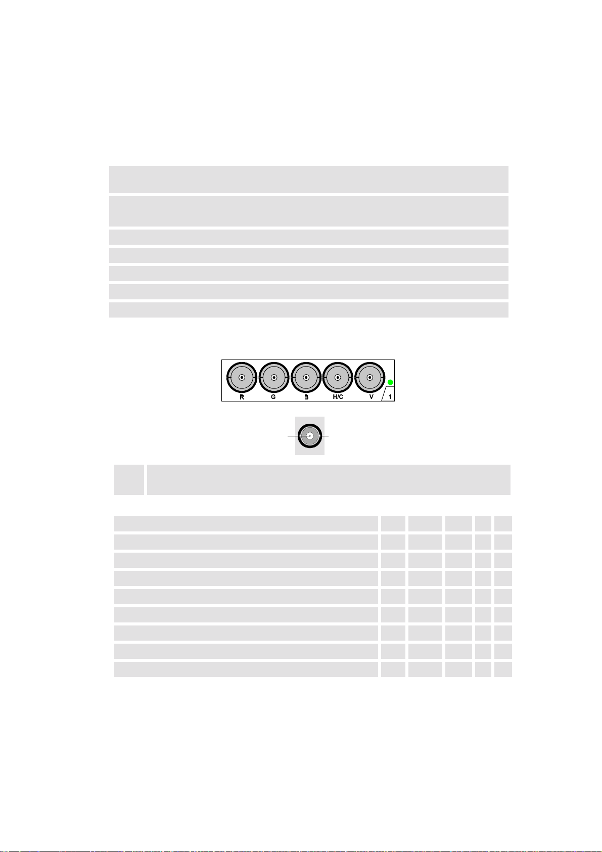
12.4 Interfaces
2
12.4.1 24V Interface
This interface allows switching the projector on and
without using the
off
or the local
RCU
Switching is done by applying a voltage (24V). The interface is made accessible via a two pole
connector mounted at the bottom of the cover.
interface two pole connector
2×0.75mm², red/black
configuration Plus(+)-pole: red
Minus(-)-pole: black
voltage 0-50 V
current max. 30mA
standby 0-5V
projector ON: 12-32V
insulation voltage: 5300V
12.4.2 Slot 1: 5 cable input, 5×BNC
keypad
.
1
Signal
1
Shield
2
Connector name R G B H V
Input signal
RGBHV R G B H V
RGBS R G B S -
RGsB R Gs B - -
Composite Video - Video - - -
Super Video - Y - - C
Component Video - SS R-Y Y B-Y S -
Component Video - SOY R-Y Ys B-Y - -
Table 12-4
R5976255
ATLAS
CS4 (2001-03)
12-5
Page 91

12.4.3 Slot 2: Computer input/Monitor output
2
Red
1
Green
2
Blue
3
Green
4
ground
5
12.4.4 Slot 3: Video Input
ground
6
ground
7
ground
8
loop through to monitor
9
ground
10
1
5
10
15
loop through to monitor
11
loop through to monitor
12
HSYNC / CSYNC
13
VSYNC
14
loop through to monitor
15
1
6
11
Table 12-5
1×BNC or cinch 1.0Vpp ± 3 dB, no loop through
Signal
1
Shield
2
12.4.5 Slot 4: S-Video Input
ground luminance
1
ground chrominance
2
4
3
12
luminance 1.0Vpp ± 3 dB
3
chrominance 282 mVpp ± 3 dB
4
Table 12-6
Table 12-7
R5976255
ATLAS
CS4 (2001-03)
12-6
Page 92
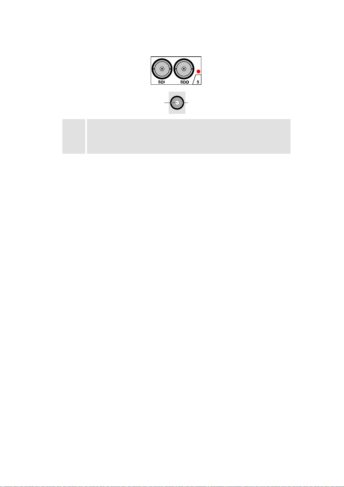
12.4.6 Slot 5: Serial digital Input / Serial digital Output
2
1
Signal
1
Shield
2
BNC input, 75 Ω terminated
SDI
SDO
BNC output, output impedance 75 Ω
Table 12-8
R5976255
ATLAS
CS4 (2001-03)
12-7
Page 93

12.5 Parts List
12.5.1 Optional Parts
order No. designation
R9829960 Executive Remote Control
R9827890 VS05
12.5.2 User’s Manuals
order No. title
R5976255 User’s Manual A
R5975765 Owner’s manual RCVDS05
R5975245 Owner’s manual VS05
TLAS
CS4 -
Table 12-9
SERIE
Table 12-10
R5976255
ATLAS
CS4 (2001-03)
12-8
Page 94

12.6 Addresses
Feel free to contact us if you have any further questions!
!
Barco Control Rooms GmbH
An der Rossweid 5 • D-76229 Karlsruhe • Germany
Phone (49) (721) 6201-0 • Fa× (49) (721) 6201-298
E-mail
info.bcd.de@barco.com
!
BARCO Projection Systems - Europe
, Web
www.barco.com
Noordlaan 5 • B-8520 Kuurne • Belgium
Phone (32) (56) 36-8211 • Fa× (32) (56) 36-8251
E-mail
sales.bcd@barco.com
• Web
www.barco.com
R5976255
ATLAS
CS4 (2001-03)
12-9
Page 95

13 Configuring Notes
A number of design and ergonomic conditions must be considered when planning the installation
TLAS
of A
technical requirements which must be observed in a specific application.
CS4. In addition to mounting dimensions, the following sections also include anthropo-
R5976255
ATLAS
CS4 (2001-03)
13-1
Page 96

13.1 Floor Space And Maintenance Area
TLAS
Sufficient floor space and maintenance area must be available when installing A
CS4
Floor Space
The floor space must have a sufficient load carrying capacity and be sufficiently flat (according to
DIN 18202). It must not sag by more than 1 millimeter under the load of the A
TLAS
CS4. A ce-
ment, wood or false floor is permissible.
The load of the A
TLAS
CS4 is transmitted to the floor via adjustable feet.
No installations (venting ducts, sockets etc.) must be present in the floor in the area of the feet or
of the lower anchoring devices. An area of at least 15 centimeters must be kept free around each
foot. The loading capacity in the area of the feet must be sufficient. Height differences up to
±5 millimeters can be compensated using the adjustable feet.
TLAS
A
67 CS4
752,5
154.5
front
1335
top
side
Figure 13-1
TLAS
Position of the feet of A
(All dimensions measured in millimeters!)
67 CS4
R5976255
ATLAS
CS4 (2001-03)
13-2
Page 97

TLAS
A
84 CS4
front
1650
1035
154.5
top
side
Figure 13-2
TLAS
Position of the feet of A
84 CS4
(All dimensions measured in millimeters!)
Maintenance Area
The floor space for a Atlas Unit is calculated from the basic area of the structure. A maintenance
area must be provided behind each Atlas Unit over the complete width. This area must be permanently accessible. The exact regulations for such a maintenance area can be obtained from the
specifications for working premises.
>700
service area
>700
service area
885
2002
Figure 13-3
Linear and polygonal set-up of A
(All dimensions measured in millimeters!)
The Atlas Units can have a linear or curved arrangement. With a curved design, the modular aluminum structure is built with angled connecting plates. The angle between two columns can vary
between 0 and 8°.
R5976255
ATLAS
CS4 (2001-03)
TLAS
CS4
13-3
Page 98

13.2 Overall Height
0
1335
The installation room must be sufficiently high. Sufficient space (recommended > 100 millimeters) must be provided above the Atlas Units. The total height results from the height of the supporting construction plus the height of the Atlas Units with feet plus the vacant space above the
modules.
TLAS
A
67 CS4
finished ceiling
finished floor
The depth of the A
TLAS
100
1068
1068
between 492
and 1287,5 mm
67CS4 W
100
finished window
2 x 1335 +45
(All dimensions measured in millimeters!)
ALL
is 929.5mm. The standard screen height with the adjustable
feet is 1287.5 millimeters. Other heights are available on request.
Mounting dimensions of A
10
Figure 13-3
TLAS
67 CS4
R5976255
ATLAS
CS4 (2001-03)
13-4
Page 99

TLAS
0
1650
A
84 CS4
finished ceiling
finished floor
The depth of the A
TLAS
100
1320
1320
between 366
and 1287,5 mm
84 CS4 W
100
finished window
2 x 1650 +45
(All dimensions measured in millimeters!)
ALL
is 1212mm. The standard screen height with the adjustable
feet is 1287.5 millimeters. Other heights are available on request.
Mounting dimensions of A
10
Figure 13-4
TLAS
84 CS4
R5976255
ATLAS
CS4 (2001-03)
13-5
Page 100
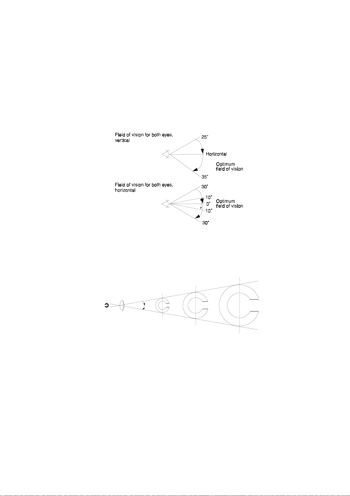
13.3 Viewing Distance and Angle
V
i
b
j
TLAS
When planing the installation of A
CS4, anthropotechnical factors such as the human field of
vision must be considered in addition to design requirements. General rules for the viewing angle
and distance will not be specified here since they depend on the field of application. The notes in
this section are therefore only recommendations which can be observed for a particular application.
In the case of permanent, intensive viewing of the display, the display should be in the field of vision of both eyes of the observer. The following figure shows the horizontal and vertical angles of
the field of vision with both eyes. An optimum field of vision can be defined for the horizontal
field.
Human field of vision for both eyes
Figure 13-5
The maximum viewing distance depends on the minimum character size used. Characters and upper-case letters should appear to the eye at an angle of vision greater than 18 angular minutes. This
corresponds to a viewing distance less than 200 times the character height.
Image
on retina
ewedo
Angle of vision
ects
Figure 13-2
Angle of vision
R5976255
ATLAS
CS4 (2001-03)
13-6
 Loading...