

Page 1
Athena
R5906789/02
26/01/2018
User manual
Page 2

Barco Visual (Beijing) Electronics Co., Ltd
地址:北京市 昌平区 中关村科技园 昌平园 昌盛路 16号
Phone: +86 10 8010 1166
Fax: +86 10 8970 2793
Support: www.barco.com/en/support
Visit us at the web: www.barco.com
Barco NV
President Kennedypark 35, 8500 Kortrijk, Belgium
Phone: +32 56.36.82.11
Fax: +32 56.36.883.86
Support: www.barco.com/en/support
Visit us at the web: www.barco.com
Printed in Belgium
Page 3

Changes
Barco provides this manual ’as is’ without warranty of any kind, either expressed or implied, including but not limited to the implied warranties or m erchantability and fitness for a particular purpose. Barco may make improvements and/or changes to the product(s) and/or the
program(s) described in this publication at any time without notice.
This publication could c ontain technical inaccuracies or typographical errors. Changes are periodically made to the information in this
publication; these changes are incorporated in new editions of this publication.
The latest edition of Barco manuals can be downloaded from the Barco web site w
h
ttps://www.barco.com/en/signin.
ww.barco.com or from the secured Barco web site
Copyright ©
All rights reserved. No part of this document may be copied, reproduced or translated. It shall not otherwise be recorded, transmitted or
stored in a retrieval system without the prior written consent of Barco.
Federal Communications Commis sion (FCC Statement)
This equipment has been tested and found to comply with the limits for a class A digital device, pursuant to Part 15 of the FCC rules.
These limits are designed to provide reasonable protection aga inst harmful interference when the equipment is operated in a commercial
environment. This equipment generates, uses, and can radiate radio frequency energy and, if not installed and used in accordance with
the instruction m anual, may cause harmful interference to radio communications. Operation of this equipment in a residential area may
cause harmful interference, in which case the user will be responsible for correcting any interference at his own expense
Changes or modifications not expressly approved by the party responsible for compliance could void the user’s authority to operate the
equipment
EN55022/CISPR22 Class A ITE (Information Technology Equipment)
Class A ITE is a category of all other ITE which satisfies the class A IT
be restricted in its sale but the following warning shall be included in the instructions for use:
Warning : This is a class A product. In a domestic environment this product may cause radio interference in which case the user may be
required to take adequate measures. Contact the installer.
Warning : This equipment is c ompliant with Class A of CISPR 32. In a residential environment this equipment may cause radio interference.
E limits but not the class B ITE limits. Such equipment should not
Guarantee and Compensation
Barco provides a guarantee relating to perfect manufacturing as part of the legally stipulated terms of guarantee. On receipt, the purchaser
must immediately inspect all delivered goods for damage inc urred during transport, as well as for material and manufacturing faults Barco
must be informed immediately in writing of any complaints.
The period of guarantee begins on the date of transfer of risks, in the case of special systems and software on the date of commissioning,
at latest 30 days after the transfer of risks. In the event of justified notice of complaint, Barco can repair the fault or provide a replacement
at its own discretion within an appropriate per
reduction in the purchase price or cancellation of the contract. All other claims, in particular those relating to compensation for direct or
indirect damage, and also damage attributed to the operation of software as well as to o ther services provided by Barco, being a component
of the system or independent service, will
guaranteed in writing or due to the intent or gross negligence or part of Barco.
If the purchaser or a third party carries out modifications or repairs on goods delivered by Barco, or if the goods are ha ndled incorrectly,
in particular if the systems are o perated incorrectly or if, after the transfer o f risks, the goods are subjec t to influences not agreed upon in
the contract, all guarantee claims of the purchaser will be rendered invalid. Not included in the guarantee co verage are system failures
which are attributed to programs or s pecial electronic circuitry provided by the purchaser, e.g. interfaces. Normal wear as well as norm al
maintenance are n ot subject to the guarantee provided by Barco either.
The environmental conditions as well as the servicing and m aintenance regulations specified in this manual m ust be complied with by the
customer.
iod. If this measure proves to be impossible or unsuccessful, the purchaser ca n demand a
be deemed invalid provided the damage is not proven to be attributed to the absence of pr operties
Software License Agreement
You should carefully read the following terms and conditions before u sing this software. Your use of this software indicates your acceptance
of this license agreement and warranty.
Terms and Conditions:
1. No redistribution of the software is allowed.
2. Reverse-Engineering. You m ay not reverse engineer, decompile, disassemble or alter this software product.
Disclaimer of Warranty:
Page 4

This software and the accompanying files are sold “as is” and without warranties as to performance or merchantability or any other warranties whether expressed or im plied. In no event shall B arco be liable for damage of any kind, loss of data, loss of profits, business
interruption or o ther pecuniary loss arising directly or indirectly. Any liability of the seller will be exclusively limited to replacement of the
product or refund of purchase price.
Trademarks
Brand and product names mentioned in this manual may be t rademarks, registered trademarks or copyrights of their respective holders.
All brand and product names mentioned in this manual serve as commen ts or examples and are not to be understood as advertising for
the products or their m anufacturers.
Page 5

Table of contents
TABLE OF CONTENTS
1. Welcome ......... ................ ................ ................ ................ ................ ................ .... 3
1.1 About this manual . . .................................................................................................................. 3
2. Safety................................................................................................................. 5
2.1 General considerations ............................................................................................................... 5
2.2 Safety training to be provided by theinstaller ....................................................................................... 6
2.3 Important safety instructions ......................................................................................................... 7
2.4 Light beam Hazard Distance (HD) ................................................................................................... 9
2.5 HD in function of the lens Throw Ratio (TR)........................................................................................10
3. Lenses & Lens selection.........................................................................................11
3.1 Lens removal ........................................................................................................................ 11
3.2 Lens shift, zoom & focus . . .......................................................................................................... 12
4. Input & Communication ..........................................................................................15
4.1 Introduction ..........................................................................................................................15
4.2 Local Keypad ........................................................................................................................16
4.3 Projector Status......................................................................................................................17
4.4 Cinema Controller ...................................................................................................................19
4.5 Integrated Cinema Processor (ICP) ................................................................................................ 21
4.6 HD-SDI Input Module (optional).. . ..................................................................................................22
4.7 Integrated Media Block/Server (op tional) . . .........................................................................................25
5. ICMP ............ ................ ................ ................ ................ ................ ................ .....27
5.1 ICMP introduction. . . .................................................................................................................27
5.2 ICMP HDD........................................................................................................................... 29
5.3 ICMP communication ports .........................................................................................................30
5.4 ICMP s ource input ports............................................................................................................. 31
5.5 ICMP D isplayPort specifications....................................................................................................33
5.6 ICMP SDI specifications.............................................................................................................34
5.7 ICMP HDMI 2.0 s pecifications ......................................................................................................37
5.8 ICMP HDMI 1.4 s pecifications ......................................................................................................40
5.9 ICMP status LEDs...................................................................................................................42
5.10 ICMP HDD status LEDs.............................................................................................................43
5.11 ICMP dev ice certificate.............................................................................................................. 44
5.12 ICMP c onfiguration via Communicator ............................................................................................. 46
5.13 ICMP reset...........................................................................................................................47
5.14 Obtaining the Barco ICMP certificate...............................................................................................48
5.15 Removing a HDD from the ICMP ...................................................................................................48
5.16 Installing a HDD into the ICMP......................................................................................................49
6. Communicator Touch Panel .............. ................ ................ ................ ................ .......51
6.1 Communicator Touch Panel.........................................................................................................51
6.2 Installing the Touc h Panel interface.................................................................................................52
6.3 Repositioning the Touch Panel interface . . . ........................................................................................54
7. Starting up..........................................................................................................57
7.1 Switching the Athena O N .. .........................................................................................................57
7.2 Switching the Athena O FF . .........................................................................................................58
A. Specifications ............ ................ ................ ................ ................ ................ ...........59
A.1 Specifications of the Athena ........................................................................................................59
A.2 Specifications of the ICMP .......................................................................................................... 60
A.3 Dimensions of the A thena .. .........................................................................................................61
A.4 Dimensions of the universal pedestal...............................................................................................62
A.5 Technical Regulations ............................................................................................................... 62
B. Environmental information .. ................ ................ ................ ................ .................. ...63
B.1 Disposal information................................................................................................................. 63
B.2 China RoHS compliance ............................................................................................................64
B.3 Taiwan RoHS compliance ........................................................................................................... 65
B.4 Turkey RoHS compliance ........................................................................................................... 66
B.5 Hazards..............................................................................................................................66
B.6 Contact information.................................................................................................................. 66
B.7 Production address ..................................................................................................................66
B.8 Download Product Manual . .........................................................................................................67
Glossary .......... ................ ................ ................ ................ ................ ................ .......69
Index..................... ................ ................ ................ .................. ................ ............... 71
R5906789 ATHENA 26/01/2018 1
Page 6

Table of contents
2 R5906789 ATHENA 26/01/2018
Page 7

1. Welcome
1. WELCOME
Congratulations
May we c ongratulate you on your purchase of a Barco Athena! It is our sincere wish that this digital projector meets u p to your every
expectation and that y ou thereby take a little time to page through this important manual. Familiarizing yourself with it’s features,
important safety instructions and necessary maintenance actions, w ill ensure you enjoy many years of reliable, trouble-free high
quality performance.
Overview
• About this manual
1.1 About this manual
How to use this manual?
We suggest that you read o ver this m anual before you install and use your Athena. Inside it, you will find important information
regarding safety, installation and maintenance. We urge even the experienced user to take the necessary time to page through this
manual. We believe everyone will benefit from this manual. Not in the least our editors, who will sleep more comfortably knowing
their efforts have had their effect.
What’s expected from you?
For your safety and in th e interest of reliable, trouble-free,
to follow all instructions precisely. Follow the maintenance recommendations and procedures in this manual step by step to keep
your projector in excellent condition. Doing so will directly impact the lifetime of your A the na.
If, after having read over these instructions, you ex perience difficulties, please contact your Barco service partner! They will do their
best to assist you and get you up and running as soon as possible.
“Treat your Athena as your own and it will reward you with m any trouble-free years of exquisite digital entertainment pleasure!”
high quality performance, we urge the user/operator/service technician,
R5906789 ATHENA 26/01/2018
3
Page 8

1. Welcome
4 R5906789 ATHENA 26/01/2018
Page 9
2. SAFETY
About this chapter
Read this chapter attentively. It contains impo rtant information to prevent personal injury while installing and using your Athena.
Furthermore, it includes several cautions to prevent damage to your Athena. Ensure that you understand and follow all safety
guidelines, safety instructions and warnings mentioned in this chapter be fore installing and using the Athena. After this chapter,
additional “warnings” and “cautions” are given depending on the procedure. Read and follow these “warnings” and “cautions” as
well.
Clarification of the term “Athena” used in this document
When referring in this document to the term “Athena” means that the content is applicable for following Barco products:
•ATHENA
Barco provides a guarantee relating to perfect manufacturing as part of the legally stipulated terms of guarantee. Observing the specification mentioned in this chapter is critical for projector performance. Neglecting
this can result in loss of warranty.
Model certification name
• Athena : DP2K-6E
Overview
2. Safety
• General considerations
• Safety training to be provided by the installer
• Important safety instructions
• Light beam Hazard Distance (HD)
• HD in function of the lens Throw Ratio (TR)
2.1 General considerations
WARNING: Ensure you understand and follow all the safety guidelines, safety instructions, warnings and
cautions mentioned in this manual.
WARNING: Be aware of suspended loads.
CAUTION: High pressure lamp may explode if imprope
General safety instructions
rly handled.
• Before operating this equipment please read this manu al thoroughly and retain it for future reference.
• Installation and preliminary adjustments should be performed by qualified Barco personnel or by authorized Barco service dealers.
• All warnings on the projector and in the doc umentation manuals should be adhered to.
• All instructions for operating and use of this equipment must be followed precisely.
Notice on safety
This equipment is built in accordance with t he requirements of the international safety standards IEC60950-1, EN60950-1,
UL60950-1 and CAN/CSA C22.2 No.60950-1, which are the safety standards of information technology equipment including
electrical business equipment. These safety standards impose important requirements on the use of safety critical components,
materials and insulation, in order to protect the user or operator against risk of electric shock and energy hazard and having access
to live parts. Safety standards also impose limits to the internal and external temperature rises, radiation levels, mechanical stability
R5906789 ATHENA 26/01/2018
5
Page 10

2. Safety
and strength, enclosure construction and protection against the risk of fire. Simulated single fault condition testing ensures the
safety of the equipment to the user even when the equipment’s normal operation fails.
Owner’s record
The part number and serial number are printed on a label which is stuck on the respective part. Record these numbers in the spaces
provided below. R efer to them whenever you call upon your Barco dealer regarding this product.
Product article number
Product serial number
Dealer
2.2 Safety training to be provided by the installer
WARNING: The installer is responsible that the user is instructed. The user will sign a docu men t to confirm
that the instructions have been received and understood.
Users definition
The Athena is intended for persons who have been instructed and trained by a skilled person (installer or service personnel) to
identify energy sources that may cause injury and to take precautions to avoid unintentional contact with or exposure to those energy
sources.
The skilled person mus t instruct the user about:
• High intensity light bea m. The user must respect the exclusion zone, based on the light beam Hazard Distance (HD).
• Dangerous energy sources inside the projector. The user is not allowed to remove any cover from the projector.
• Small glass parts can leave the projector in the ev ent of lamp explosion. Keep 1 m (40 in.) distance from the air outlet side of
the projector during operation.
• The installation, m aintenance or service is for skilled persons only.
• The requirements for a restricted access location and an exclusion zone.
Restricted access location
To protect untrained persons and children, the projector must be installed in a restricted access location. The definition of a
restricted access location is a location for equipment where both of the following paragraphs apply:
• Access can only be gained by skilled persons ( installer or service personnel) or persons who have been instructed and trained
by a skilled person. The persons must have been instructed about the reasons for the restriction applied to the location and
about the precautions that shall be taken.
• Access is only possible through the use of the tool or lock and key, or other means of s ecurity, and is controlled by the authority
responsible for the location.
Exclusion zone
The projector radiates hea t on its external surfaces and from ventilation ducts during normal operation. Exposing flammable or
combustible materials into close proximity of this projector could result in the spontaneous ignition of that m aterial, resulting in a
fire. For this reason, it is absolutely necessary to leave an exc lusion zone around all external surfaces of the projector whereby no
flammable or combustible materials are present:
• The exclusion zone must not be less than 40 cm (16 in.).
• Loose papers or other objects may not be nearer to the projector than 10 cm (4 in.) on any side.
• Rear exhaust: the exclusion zone on the rear side must not be less than 1 m (40 in.).
To protect untrained users and children against high intensity light beams, the light beam Hazard Distance (HD) shall be taken into
account. See "Light beam Hazard Distance (HD)", page 9.
6
R5906789 ATHENA 26/01/2018
Page 11

2.3 Important safety instructions
To prevent the risk of electrical shock
• Installation according to the local electrical c ode and regulations by qualified technical personnel only.
• A readily accessible disconnect device must be incorporated externally to the equipment for removal of the power to the pr ojector cord.
• Warning: High leakage current. Earth connection essential before connecting supply.
• Do not allow anything to rest on the power cord. Do not locate this projector where persons will walk on the cord.
• Do not op erate the projector with a damaged cord or if the projector has been dropped or damaged - until it has been examined
and approved for operation by a qualified service te chnician.
• Position the cord so that it will not be tripped over, pulled, or contact hot surfaces.
• If an extension cord is necessary, a cord with a current rating at least equal to that of the projector should be used . A cord rated
for less amperage than the projector may overheat.
• Never push objects of any kind into this projector through cabinet slots as they may touch dangerous voltage points or short
circuit parts that could result in a risk of fire or electrical shock.
• Do not expose this projector to rain or moisture.
• Do not immerse or expose this projector in w ater or other liquids.
• Do not spill liquid of any kind on this projector.
• Should any liquid or solid object fall into the cabinet, unplug the set and have it checked by qualified service personnel before
resuming operations.
• Do not disassemble this projector, always take it to a trained service person when service or repair work is required.
• Do not use an accessory attachm ent which is not recommended by the m anufacturer.
• Lightning - For added protection for this video product during a lightning storm, or when it is left unattended and unused for
long periods of time, remove all power from the projector. This will prevent damage to the projector due to lightning and AC
power-line surges.
2. Safety
To prevent personal injury
• Caution: High pressure lam p may explode if improperly handled. Refer servicing to qualified service personnel.
• To prevent injury, take note of the weight of the projector. Minimum 4 adult persons are n
• To prevent injury, ensure that the lens and all cover plates are correctly installed. See installation procedures.
• Warning: high intensity light beam. NEVER look into the lens ! High luminance could result in damage to the eye.
• Warning: extremely high brightness lamps: This projector uses extremely high brightness lamps. Never attempt to look
directly into the lens or at the lamp. If the pr ojection distance is less than 6 meter, any person needs to be at least 4 meters
away from the projected image. Avoid close range reflection of the projected image on a ny reflecting surface (such as glass,
metal, …) . When operating the projector, we strongly recommend wearing suitable safety g lasses.
• Do not place this equipment on an unstable cart, stand, or table. The product may fall, causing serious damage to it and
possible injury to the user.
• It is hazardous to operate without lens or shield. Lenses, shields or ultra violet screens shall be changed if they have become
visibly damaged to such an extent that their effectiveness is im paired. For example by cracks or deep scratches.
• Warning: Protection from ultraviolet radiation: Do not look directly in the light beam. T he lamp contained in this p roduct is
an intense source of light and heat. One component of the light emitted from this lamp is ultraviolet light. Potential eye and skin
hazards are present when the lamp is energized due to ultraviolet radiation. Avoid unnecessary exposure. Protect yourself and
your employees by ma king them aware of the hazards and how to protect themselves. Protecting the skin c an be accomplished
by wearing tightly woven garments and gloves. Protecting the eyes from UV c an be accomplished by wearing safety glasses
that are designed to provide UV protection. In addition to the UV, the visible light from the lamp is intense and should also be
considered when choosing protective eye wear.
• Mercury Vapor Warnings: Keep the following warnings in mind when using the projector. The lamp use d in the projector
contains mercury. In case of a lamp rupture, explosion there will be a mercury vapor emission. In order to minimize t he potential
risk of inhaling mercury vapors:
- Ensure the projector is installed only in ventilate
- Replace the lamp module before the end of its operational life.
- Promptly ventilate the room after a lamp rupture, explosion has occurred, evacuate the room (particularly in case of a preg-
nant woman).
- Seek medical attention if unusual health conditions occur after a lamp rupture, explosion, such as headache, fatigue, short-
ness of breath, chest-tightening coughing or nausea.
• Exposure to UV radiation: Some medications are known t
Conference of Governmental Industrial Hygienists (ACGIH) recommends occupational UV exposure for an-8 hour day to be
less than 0,1 micro-watts per square centimeters of effective UV radiation. An evaluation of the workplace is advised to assure
employees are not exposed to cumulative radiation
d rooms.
o make individuals extra sensitive to UV radiation. The American
levels exceeding these government guidelines.
eeded to carry the projector.
R5906789 ATHENA 26/01/2018
7
Page 12

2. Safety
To prevent fire hazard
• Do not place flamma ble or combustible materials near the projector!
• Projection rooms m ust be well ventilated or cooled in order to avoid build up of heat. It is necessary to vent hot exhaust air from
console to the outside of the building.
• Heat sensitive materials should not be placed in the path of the exhaust a ir or on the lamp house.
To prevent projector damage
•Theairfilters of the projector must be cleaned or replaced on a regular basis (a "clean" booth would be m onthly-minimum).
Neglecting this could result in disrupting the air flow inside the projec tor, causing overheating. Overheating may lead to the
projector shutting down during operation.
• The projector must always b e installed in a manner which ensures free flow of air into its air inlets.
• In order to ensure that correct airflow is maintained, and that the projector complies with Electromagnetic Compatibility (EMC)
and safety requirements, it should always be operated with all of it’s covers in place.
• Slots and openings in the cabinet are provided for ventilation. To ensure r eliable operation of the product and to protect it from
overheating, these openings mus t not be blocked or covered. The openings should never be blocked by placing the p roduct
on a bed, sofa, rug, or other similar surface. This product should never be placed near or over a radiator or heat register. The
device should not be plac ed in a built-in installation or enclosure unless pro per ventilation is provided.
• Ensure that nothing can be spilled on, or dropped inside the projector. If this does ha ppen, switch off and remove all power
from the projector. Do not operate the projector again until it has been checked by qualified service personnel.
• Do not block the projector cooling fans or free air movem ent around the projector. Loose papers or other objects may not be
nearer to the projector than 10 cm (4") on an y side.
• Do not use this equipment near water.
• Proper operation of the projector can only be guaranteed in table mounting. It is not permitted to use the projector in another
position. See installation procedure for correct installation. A ceiling mount will be supported in the future.
• Special care for Laser Beams: Special care should be used when DLP projectors are used in the same room as h igh power
laser equipment. Direct or indirect hitting of a laser beam on to the lens can severely damage the Digital Mirror Devices
which case there is a loss of warranty.
• Never place the projector in direct sunlight. Sunlight on the lens can severely damage the Digital Mirror Devices
case there is a loss of warranty.
• Save the original shipping carton and packing material. They will come in handy if you ever have to ship your equipment. For
maximum protection, repack your set as it was originally packed at the factory.
• To ensure the highest optical performance and reso lution, the projection lenses are specially treated with an anti-reflective
coating, therefore, avoid touching the lens. To remove dust on the lens, use a soft dry c loth. Do not use a damp cloth, detergent
solution, or thinner.
• Rated maximum ambient temperature, t
= 35°C (95°F).
a
TM
TM
in which
in
On servicing
• Do not attempt to service this product yourself, as opening or removing covers may expose you to dangerous voltage potentials
and risk of electric shock.
• Refer all s ervicing to qualified service personnel.
• Attempts to alter the factory-set internal controls or to change other control settings not specially dis cussed in this manual can
lead to permanent damage to the projector and cancellation of the warranty.
• Remove all power from the projector and refer servicing to q
- When the power cord or plug is damaged or frayed.
- If liquid has been spilled into the equipment.
- If the product has b een exposed to rain or water.
- If the product does not o perate normally when the operating instructions are followed. Adjust only those controls that are
covered by the operating instructions since improper adjustm ent of the other controls may result in damage and will often
require extensive work by a qualified technician to restore th
- If the product has been dropped or the cabinet has been damaged.
- If the pr oduct exhibits a distinct change in performance, indicating a need for service.
• Replacement parts: When replacement parts ar e required, be sure the service technician has used original Barco replacement
parts or authorized replacement parts whic h have the same cha racteristics as the B arco original part. Unauthorized substitutions m ay result in degraded performance and reliability, fire, electric shock or other hazards. Unauthorized substitutions may
void warranty.
• Safety check: Upon completion of any service or repairs to this projector, ask the service technician to perform safety checks
to determine that the product is in proper operating condition.
• Possible explosion hazard: Always keep in mind the caution below:
ualified service technicians under the following conditions:
e pr oduct to normal operation.
WARNING: The user is not permitted to p erform or attempt any phase of xenon lam p handling or service.
Only trained and qualified technical service personnel are allowed to handle the xenon lamp.
8 R5906789 ATHENA 26/01/2018
Page 13
CAUTION: Xeno n compact arc lamps are highly pressu rized. W hen ignited, the normal operating temperature
of the bulb increases the pressu re to a level at which the bulb may explode if not handled in strict accordance
to the manufacturer’s instructions. The bulb is stable at room temperature, but may still explode if dropped or
otherwise mishandled. Whenever the lamp house, containing a xenon lamp, has to be dismantled or whenever
the protective container or cloth has to be removed from the xenon lamp, authorized protective clothing MUST
be worn!
To prevent battery explosion
• Danger of explosion if battery is incorrectly installed.
• Replace only with the same or equivalent type recommended by the manufacturer.
• For disposal of used batteries, always consult federal, state, local and provincial hazardous waste disposal rules and regulations
to ensure proper disposal.
Safety Data Sheets for Hazardous Chemicals
For safe handling information on c hemical products, consult the Safety Data Sheet (SD S). SDSs are available upon request via
safetydatasheets@barco.com.
2.4 Light beam Hazard Distance (HD)
HD
Light beam Hazard Distance (HD) is the distance from the source at which the intensity or the energy per sur face unit
becomes lower than the applicable safety limit. The light beam can thus be considered as dangerous if the operator
is closer from the source than the HD.
2. Safety
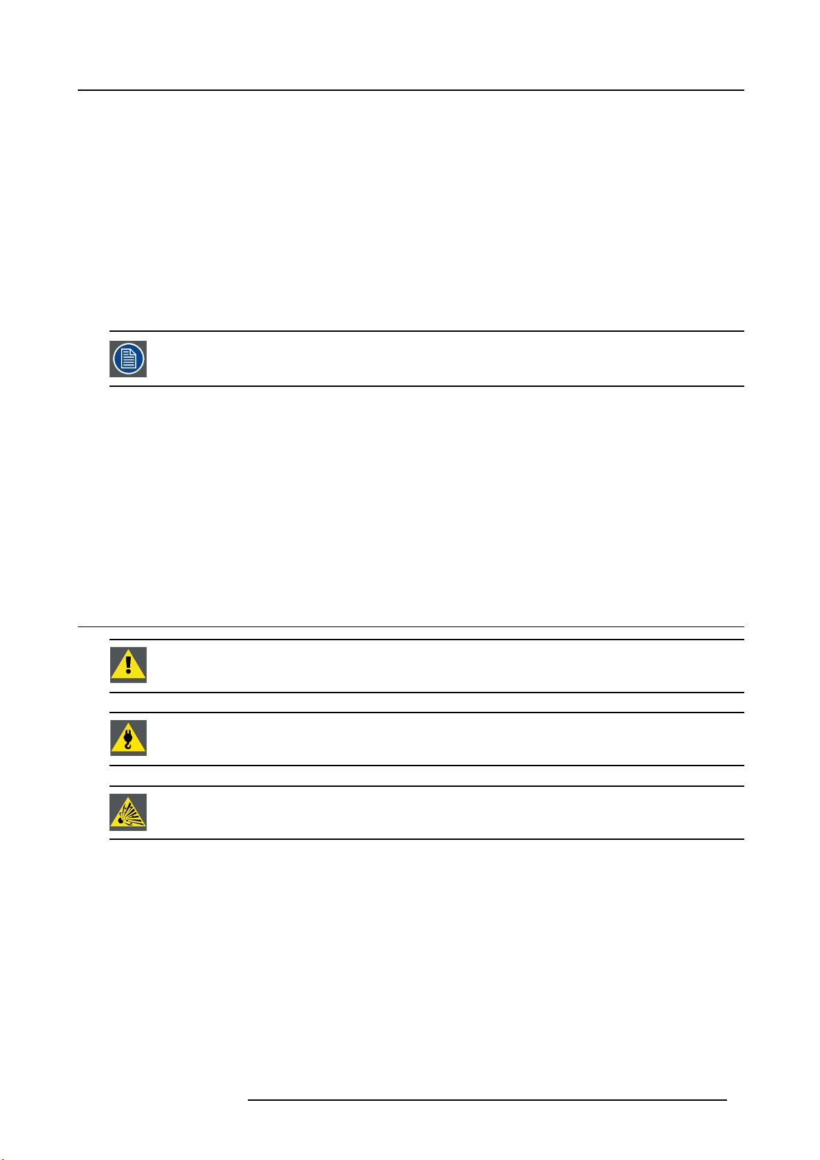
Restriction Zone (RZ) based on the HD
The HD is defined from the projection lens surface towards the position of the lowest projected beam where the irradiance equals
the applicable safety limit. T he HD depends on the amount of lumens produced by the projector and the type of lens installed. See
next chapter HD in function of the lens Throw Ratio (TR).
To protect untrained users the installation shall comply with the following installation requirements: light output levels in excess of the
limits shall not be permitted at any point less than 2.0 meters (SH image 2-1) above any surface upon which persons are assumed
to stand or 1 meter (SW image 2-1) below or in lateral separati
image 2-1.
RA TH
HD
SH
RZ
SH
Image 2-1
ASideview.
B Top view.
RA Restricted Access location (booth area of projector).
PR Projector.
TH Theater.
RZ Restriction Zone in
SH Separation Height. M ust be minimum 2 meter.
SW Separation W idth
Based on national requirements, no person is allowed to enter the projected beam within the zone between the projection lens and
the related hazard distance (HD). This s hall be physically impossible by creating sufficient separation height or by placing bar riers.
The minimum separation height takes into account the surface upon which persons are assumed to stand.
the theater.
. Must be minimum 1 meter.
on from any place where such persons a re as sum ed to be. See
TH
SW
SW
RA
PR
(B) TOP VIEW(A) SIDE VIEW
HD
SW
RZ
1m
SW
R5906789 ATHENA 26/01/2018 9
Page 14
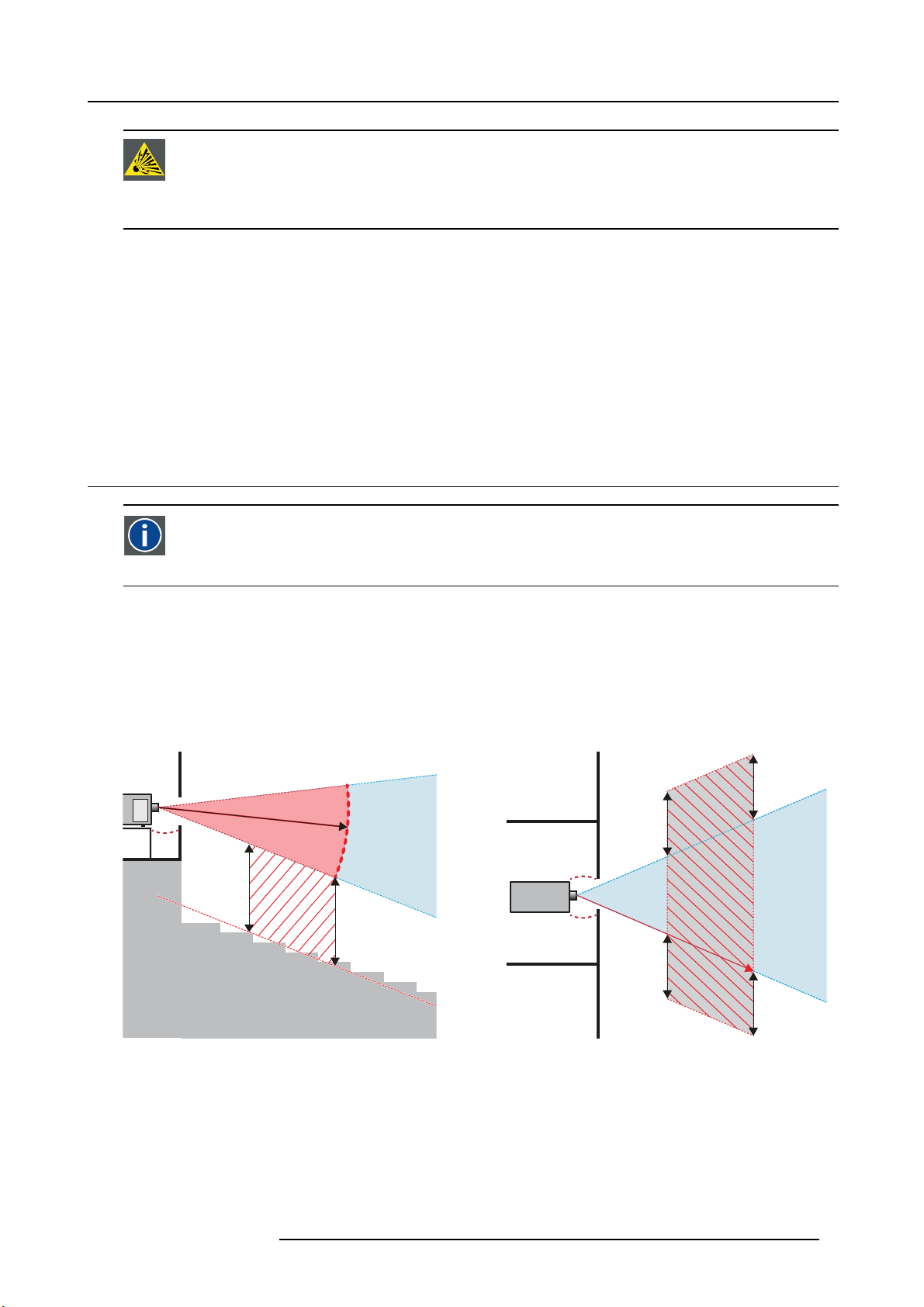
2. Safety
On image 2-1 a typical setup is displayed. It must be ve rified by the installer if these m inimum requirements are m et. If r equired a
restricted zone (RZ) in the theater must be established. This can be done by using physical barrier, like a red rope as illustrated in
image 2-2.
PR
Image 2-2
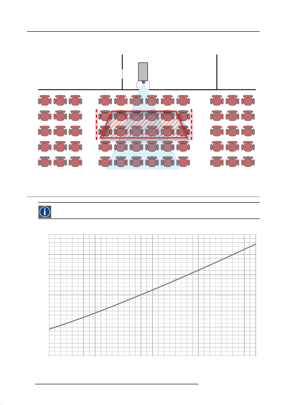
2.5 HD in function of the lens Throw Ratio (TR)
TR (Throw Ratio)
The ratio of the distance to the screen (throw) to the screen width.
Hazard Distance
1,2
1
0,8
0,6
HD [m]
0,4
0,2
0
1,0 1,2 1,4 1,6 1,8 2,0 2,2 2,4 2,6 2,8 3,0 3,2 3,4 3,6 3,8 4,0 4,2 4,4 4,6
Image 2-3
HD (in meter) in function of the Throw Ratio (TR)
TR
10 R5906789 ATHENA 26/01/2018
Page 15
3. Lenses & Lens selection
3. LENSES & LENS SELECTION
About this chapter
This chapter gives an overview of available lenses for your Athena and ex plains how to select the b est suited lens for a specific
situation using the lens calculator. Also, it is explained how to install and remove a lens from the projector Lens Holder and how to
shift, zoom and focus the lens.
CAUTION: Never transport the projector with a Lens mounted in the Lens Holder. Always remove the Le
before transporting the projector. Neglecting this can damage the Lens Holder and Prism .
CAUTION: Caution when removing or installing the lens! Fragile parts at the inner side of the Lens Holder.
Each time a lens is manipulated (e.g. removed and installed in a projector), it needs to be homed and returned.
Overview
• Lens removal
• Lens shift, zoom & focus
3.1 Lens removal
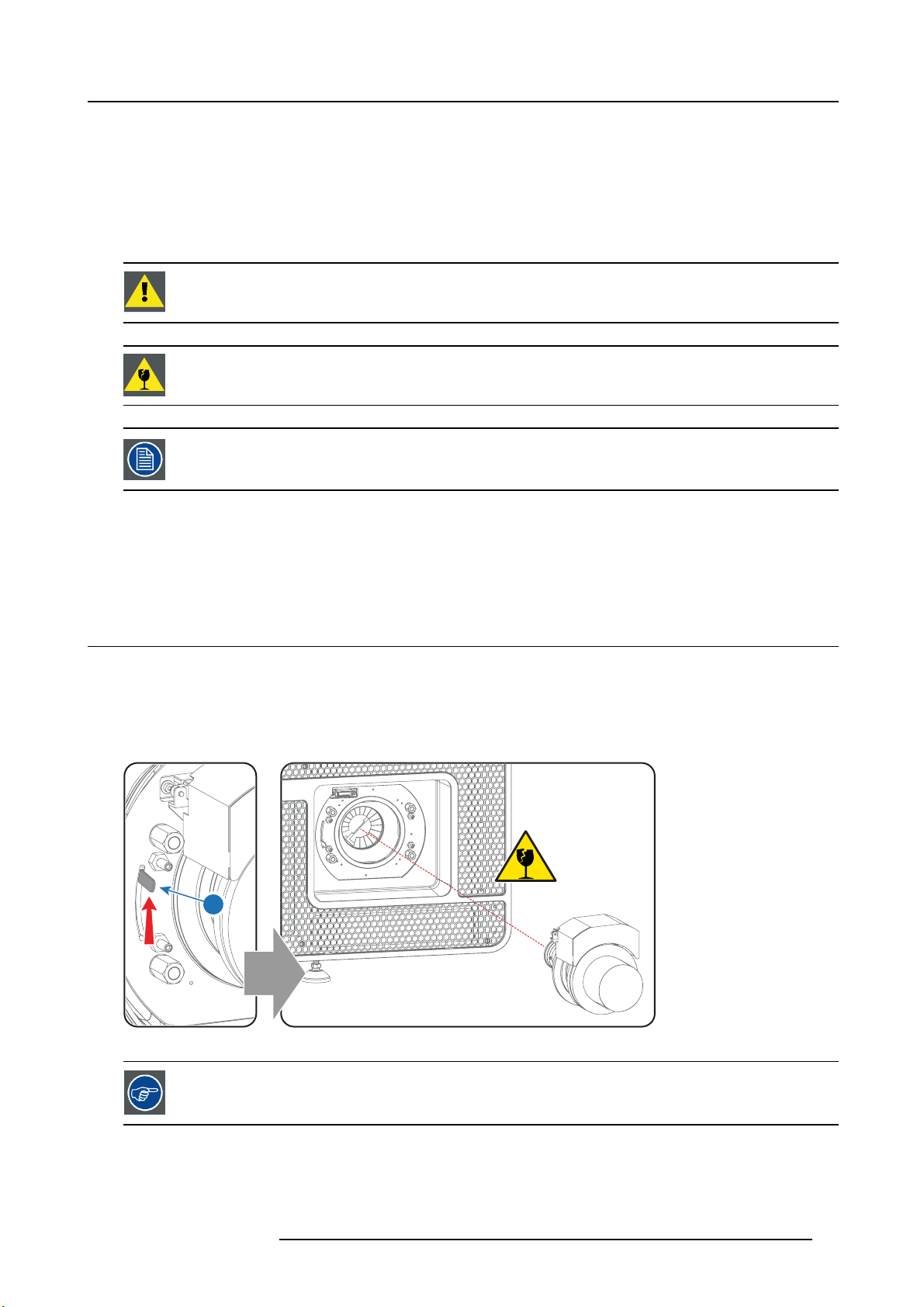
How to remove a lens from the Lens Holder?
1. S upport the lens with one hand while you unlock the lens holder by sliding the lock handle (1) towards the “unlocked” position as
illustrated.
2. G ently pull the lens out of the lens holder, maintaining its coaxial direction.
Caution: Do not accidentally bump with the lens against the elect
ronic boards inside the Lens Holder.
ns
1
Image 3-1
It’s recommended to place the Lens caps of the original Lens packaging, back on both sides o f the removed
Lens to protect the optics of the Lens.
R5906789 ATHENA 26/01/2018 11
Page 16
3. Lenses & Lens selection
SHIFT
ZOOM
It’s recommen ded to place the plastic cover of the original projector packaging, back into the Lens opening
to prevent intrusion of dust.
3.2 Lens shift, zoom & focus
Motorized lens adjustment
The Athena is equipped with a m otorized lens shift and zoom & focus functionality.
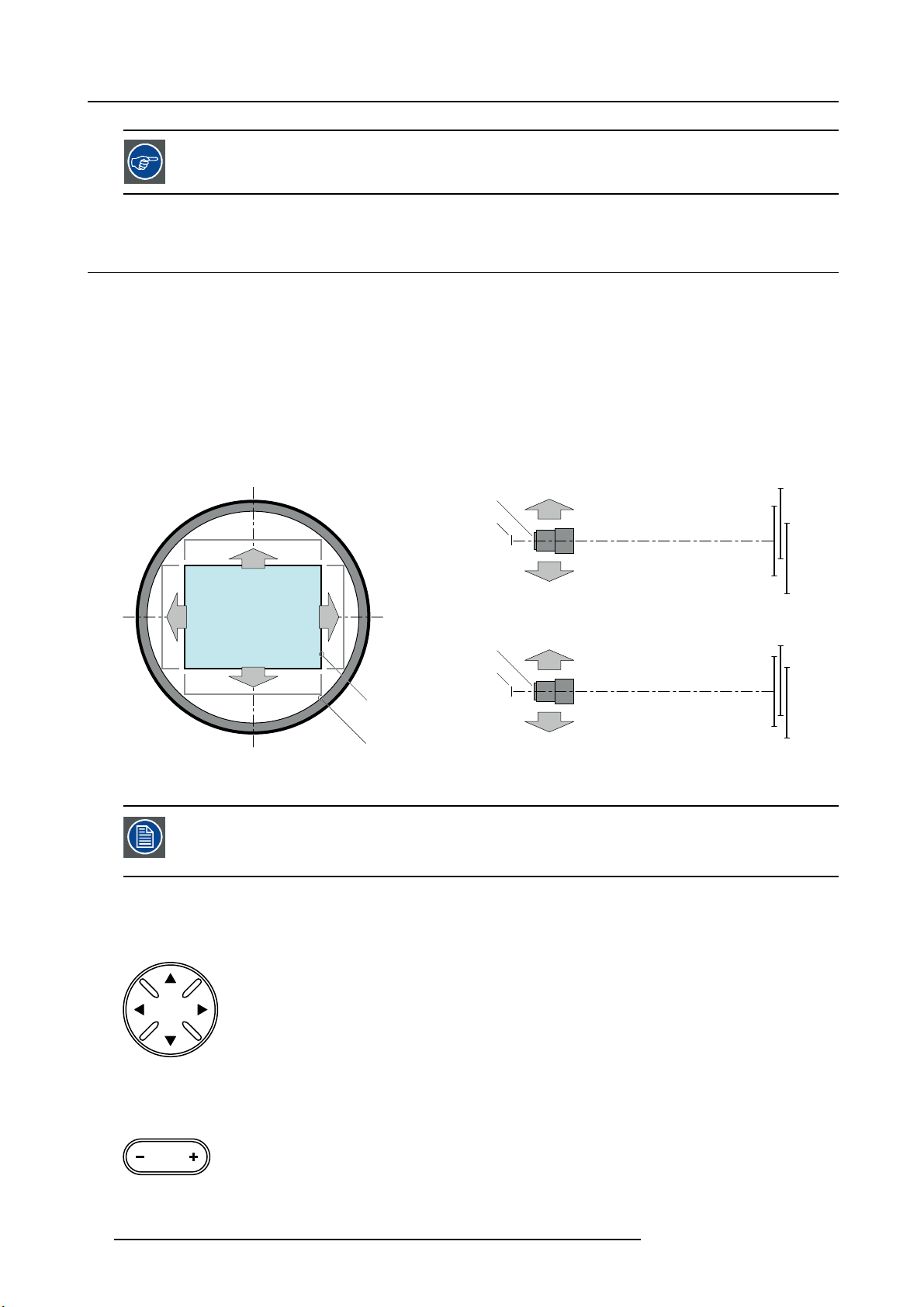
Maximum shift range
The lens can be shifted with respect to the internal optics of the projector (DMD) which results in a shifted image on the screen
(Off-Axis). A 100% shift means that the centre point of the projected image is shifted by half the screen size. In other words, the
centre point of the projected image falls together with the outline of the image in an On-Axis projection. Due to mechanical and
optical limitations the shift range is limited as well.
All lenses have a shift range of 50% up, 50% down, 30% left, and 30% right. This range is valid for all throw ratios. Within these shift
ranges the projector and lens perform excellently. Configuring the projector outside these shift ranges will result in a slight decline
of image quality.
+50%
-50%
-30%
+30%
L R
Image 3-2
PDMD.
F Field of view.
U
+50%
F
P
U
D
SIDE VIEW
-30% +30%
-50%
D
F
P
P
L
TOP VIEW
R
F
It’s mechanical p ossible to shift outside the recommended field of view (±90% UP/DOWN and ±50%
LEFT/RIGHT), but this will result in
position of the used lens. Furthermore, shifting too much in both directions will result in a blurred image
corner.
a decline of image quality depending on the used lens and the zoom
How to shift the lens of the Athena ?
1. U se the up and down arrow buttons on the Loc al Keypad to shift the lens vertically and use the left and right arrow buttons
on the Local Keypad to shift the le
ns horizontally.
SHIFT
Image 3-3
How to zoom in or out?
1. Use the “+” and “-” zoom buttons on the Local Keypad to zoom in or out.
ZOOM
Image 3-4
12 R5906789 ATHENA 26/01/2018
Page 17

3. Lenses & Lens selection
How to focus?
1. U se the “+” and “-” focus buttons on the Local Keypad to focus the image on the screen.
FOCUS
Image 3-5
Take into account that the lens focus may slightly drift while the lens is warming up from cold to operation
temperature. This is a typical phenomenon for projection lenses used with high brightness projectors. The
operation tempe rature of the lens is reached after approximately 30 minutes projection of average v
ideo.
Button backlight colors
• BLUE : The default backlight color of the Shift, Zoom and Focus buttons is blue which indicates that the button is enab led.
• PURPLE : W hen pushing the Shift, Zoom or Focus button the backlight color is purple of t he part of the button that is pushed.
This indicates that the requested action is ongoing.
• RED : The backlight color of the Shift, Zoom and Focus buttons is red in case of end of range.
R5906789 ATHENA 26/01/2018
13
Page 18

3. Lenses & Lens selection
14 R5906789 ATHENA 26/01/2018
Page 19
4. Input & Communication
4. INPUT & COMMUNICATION
About this chapter
This chapter describes the functionality of the Local Keypad, the projector Status Light (tail light) and the d ifferent input and communication ports of your A thena.
Note that all information about the ICMP is gathered into one separated chapter: "ICMP", page 27.
Overview
• Introduction
• Local Keypad
• Projector Status
• Cinema Controller
• Integrated Cinema Processor (ICP)
• HD-SDI Input Module (optional)
• Integrated Media Block/Server (optional)
4.1 Introduction
General
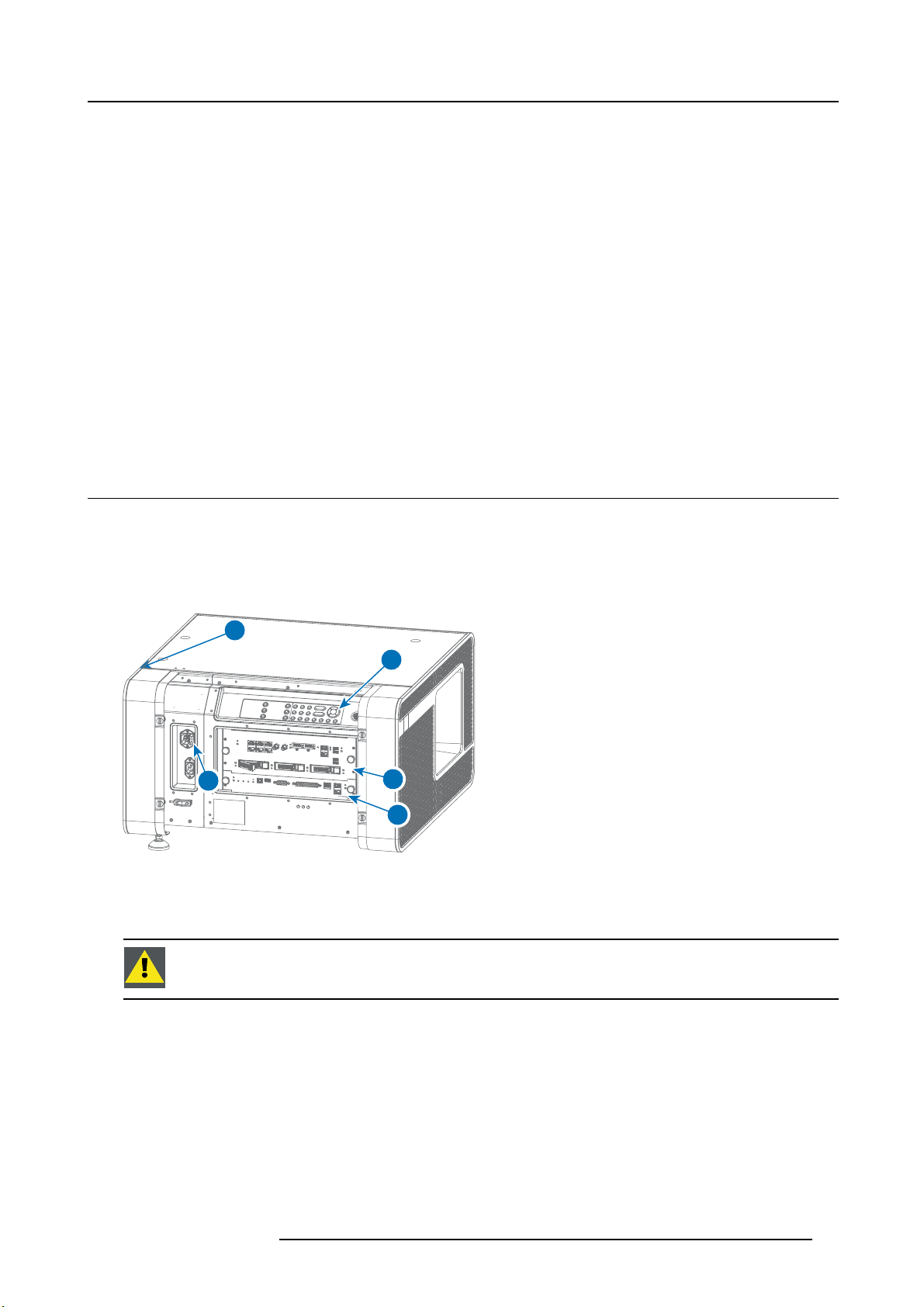
The Input & Communication side of the Athena consists of a Local Keypad integrated into the projector housing and a card cage
with three slots. The top side of the projector is equipped with a t ail light which reflects the status of the projector.
The projector card cage is equipped with an ICMP. See illustration below. Note that all information about the ICMP is gathered into
one separated chapter: "ICMP", page 27.
1
2
Image 4-1
1 Projector status light.
2 Power ON/OFF switch.
3 Local keypad.
4 Barco Cinema Controller.
5ICMP.
CAUTION: A unit may only be removed from the card c age by qualified service personnel. Removing one of
the board s (except for the Cinema Controller) will result in an authorization request upon starting.
3
5
4
R5906789 ATHENA 26/01/2018 15
Page 20
4. Input & Communication
ZOOM
SHIFT
4.2 Local Keypad
Identification of the buttons
21 3 4 5 6 7
8 9 10 11 12
1 4
2 5
DOWSER
FOCUS
SHIFT
ZOOM
3 6
Image 4-2
Functionality of the buttons
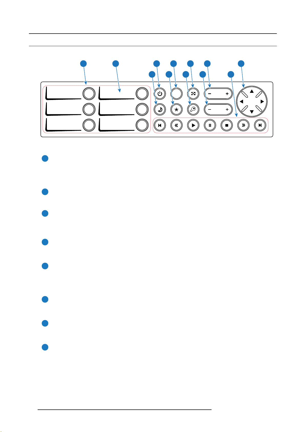
Numeric buttons (No.1 - 6)
1
All the Numeric buttons (reference 1 image 4-2) of the Local Keypad have a white backlight during normal operation.
When the au thorization process is activated with the (security) K ey button, the backlight color of the Numeric buttons
changes to yellow. Each button can be linked to a macro whic h allows you to setup the projector to your requirements
with one push of a button.
Marker area
2
Each Numeric button has a marker area (reference 2 image 4-2) where you can write down the name of the Macro.
Standby button
3
Standby b utton (reference 3 image 4-2) switches the lamp and lamp electronics immediately ON or OFF. The lamp cooling
fans remain active for about 5 minutes. The backlight color of the Standby button remains white in standby mode and
changes to green in operation mode.
Dowser button
4
The Do wser button (reference 4 image 4-2) opens or closes the electronic dowser. The backlight color of the Dowser button
is green when the dowser is open and white when the dowser is closed.
16
Test Pattern button
5
The Test Pattern button (reference 5 image 4-2) gives direct access to a limited set of the internal test patterns of the
projector. This is a toggle button. To exit the Test Pattern mode toggle through all test p atterns. Note that the convergence
test pattern is not included in this set. T he backlight color of the Test Pattern button is green if one of the test patterns
is activated and white if none is activated.
Focus button
6
The Foc us button (reference 6 image 4-2) allows you to focus the projected image on the screen. The backlight color of th e
Focus button is red in case the end of range is reached.
Shift button
7
The Shift button (reference 7 image 4-2) allows you to shift the lens up/down or left/right. The backlight color of the
Shift button is red in case the end of range is reached.
Sleep button
8
Pushing the Sleep button (reference 8 image 4-2) for 3 seconds puts the projector in Sleep mode (energy saving). In case
the projector is processing the after cooling cycle then the projector goes in Sleep m ode after finishing the after cooling
cycle. The backlight color of the S leep button is purple during a fter cooling and white in Sleep mode.
Push the Sleep button for 3 seconds in Sleep mode to aw ake the projector (put in Standby). The backlight color of the Sleep
button in Standby m ode is green.
Enter or leave Sleep mode can also be done v
Macros (not editable) with GPIO, or via the Communicator.
The Sleep button is disabled if the lamp is on.
ia a 2 dedicated projector command (USB/Ethernet), or via two predefined
R5906789 ATHENA 26/01/2018
Page 21

4. Input & Communication
Star button
9
Star button (reference 9 image 4-2). Pressing the Star button a few seconds will activate the ICMP reset process.
Key button
10
The (security) Key button (reference 10 image 4-2) is used for the authorization procedure to clear tamper errors etc.
(service pur poses). Pin codes can be added/changed with the Communicator.
Zoom button
11
The Zoom button (reference 11 image 4-2) allows you to z oom in or out the projected image on the screen. The backlight
color of the Zoom button is red in case the end of range is reached.
Media control buttons
12
Buttons (reference 12 image 4-2) allowing you to navigate through the content on the integrated media server. If a test
pattern is activated, the projector will not show the content on the integrated media server.
Button backlight colors
• PURPLE : T he backlight color of a button (or part of) is pur ple whe n pushed. This indicates that the requested action is ongoing.
The backlight color remains purple until the requested action is finished.
• GREEN : depending on the button the green backlight color can have a different meaning:
- for the Standby button a green backlight color means that the lamp is switched ON.
- for the Sleep button a green backlight color means that the projector is awake.
- for the Dowser button a green bac klight color me ans that the electronic dowser is o pen (applied source can be displayed).
- for the Test Pattern button a green backlight color means that one test pattern is activated and thus the applied source can
be displayed.
- for the Key button a green backlight color means that the projector is s ecured (no tamper event).
• RED : depending on the button the red backlight color can have a different meaning:
- for the Shift, Zoom or Focus button a red backlight color indicates that the end of range is reached.
• YELLOW : The backlight color of the Numeric buttons 1 to 6 of the Local Keypad changes from white t
Key button is pressed.
• WHITE: depending on the button the white bac klight color can have a different me aning:
- for the Standby button a white backlight color indicates that the lamp is OFF (not activated).
- for the Sleep button a white backlight color indicates that the projector is in Sleep m ode.
- for the D owser button a w hite backlight color indicates that the electronic dowser is closed (applied source can not be displayed).
- for the Test Pattern button a white backlight color indicates that no test pattern is selected (applied source can be displayed).
- for the Key button a white backlight color means that the projector is no t secured (tamper event).
o yellow if the (security)
4.3 Projector Status
About the projector Status Light
The projector Status Light is located at the rear end of the projector (Tail Light). The projector Status Light is real time indicator of
the projector condition.
R5906789 ATHENA 26/01/2018
17
Page 22
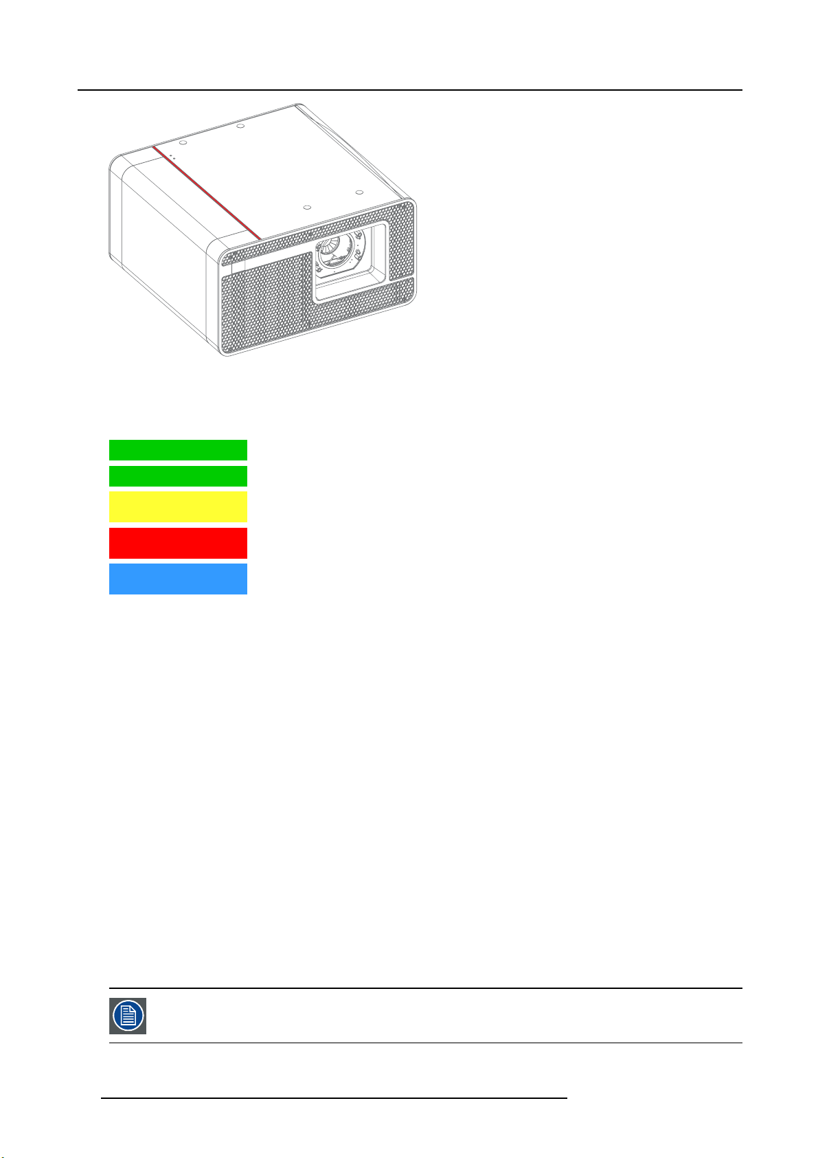
4. Input & Communication
Image 4-3
Status overview
Depending on the condition of the projector the status light may have 4 colors: Green, Yellow, Red or Blue. Eac h color r epresent a
different state:
Blinking Green Projector is booting up. (Fully booted up when Test Pattern butto
Green
Yellow Projector is running with warnings. Event can go on but a tec
Red
Blue Projector runs in notification state. Maintenance action required. Lamp run time is exceeded.
Projector is running norm ally.
the near future to prevent a complete stop of the projector.
Projector is in error state. Problem could prevent normal operation. Solve the problem before
continuing with the projector.
New lamp must be installed.
n is white as well)
hnical intervention will be necessary in
Standby mode
In Standby mode the lamp of the projector is switched OFF but all the electronics of the projector remain fully operational. The
projector is ready to ignite the lamp and project the image. The status light is not different between Standby mode and Lamp ON
mode (fully operational).
Sleep mode
If the projector is in Sleep mode then the status light flashes every ten seconds. The color of the flash depends on the state of the
projector. In other words, the color of the flash will be green in normal state (no warnings, no errors, no notifications).
In Sleep mode the total power consumption of the projector is less than 15W. No fans are turning and the Lamp Power Supply (LPS)
is switched OFF completely. Only the following functionalities of the projector remains active:
• Cinema Controller
• Local Keypad
• Router and external sw itch fully functional
• USB IN port type “ B” (Virtual comport RS232)
• USB OUT port type “A” (To power handheld d evices [500mA MAX]. No other functionality supported)
• GPIO port on the Cinema Controller
Pressing the Sleep button in Standby mode for 3 seconds puts the projector in Sleep mode. In ca se the projector is processing the
after cooling cycle then the projector goes in Sleep mode after finishing the after cooling cycle.
Pressing the Sleep button in Sleep m ode for 3 seconds will awake the projector. The status light will blink for a few seconds (booting
up all inactive boards) and then
Enter or leave Sleep mode can also be done via 2 dedicated projector command (USB/Ethernet), or via two predefined Macros (not
editable) with GPIO of the Cinema Controller (not the GPIO of the ICMP), or via the Communicator.
lights up continuously.
The p rojector always boots up in the same mode (E.g. Standby or Sleep) as it was switched OFF.
The Sleep button is disabled if the lamp is ignited.
18 R5906789 ATHENA 26/01/2018
Page 23
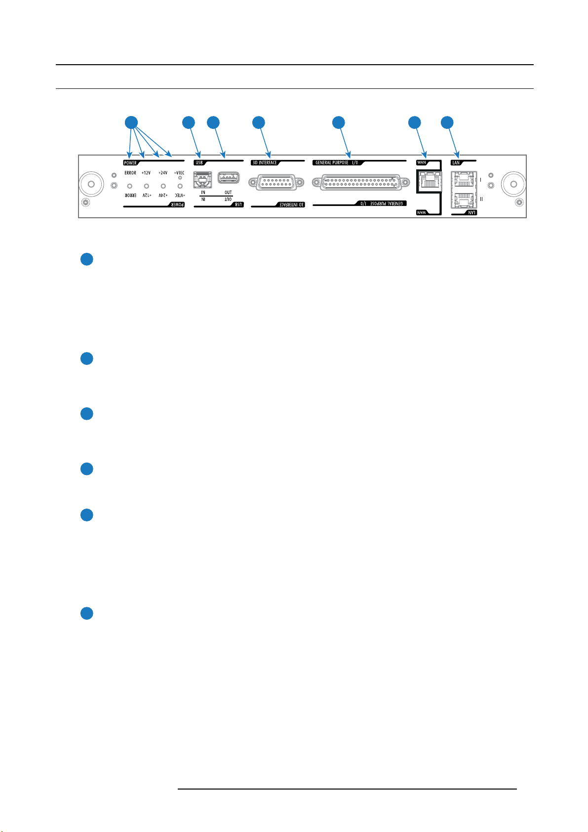
4.4 Cinema Controller
Location of the communication ports
Image 4-4
Functionality
1
Diagnostic LEDs
The front plate of the Cinema Controller contains 4 diagnostic LEDs to display the status o
image 4-4):
• +VTEC supply (not used on Athena).
• +24V supply.
• +12V supply.
• general power supply (ERROR).
4. Input & Communication
5 6 74321
f the power supply (reference 6
2
USB IN port
The Cinema Controller is equipped with a USB port, type “B” connector, (reference 5 image 4-4) to connect upstream devices
(E.g. PC). This USB port is used to communicate with the projector via RS232 commands (Virtual comport). The USB
IN port remains operational in Sleep mode.
3
USB OUT port
The Cinem a Controller is equipped with a USB port, type “A” connector, (reference 4 image 4-4) which can be used to power
handheld devices within USB spec (MAX 500mA/5V]. No other functionality supported (Future ex pansion). The USB
OUT port remains operational in Sleep mode.
4
3D INTERFACE
3D interface port (reference 3 image 4-4). Can be used to connect ex ternal 3D devices to the projector. All signals necessary
for 3D projection can be provided via this connector. The 3D interface port is disabled if the projector is in Sleep mode.
5
GENERAL PURPOSE INPUT/OUTPUT (GPIO)
This 37 pin connector (reference 2 image 4-4) can be used to send or receive trigger signals from other dev ices. These
input/output pins can be programme d by macros created with the Communicator software. See user’s guide of the
Communicator, section Macro editor, for more information about this functionality. Note that the General Purpose Inputs
accept 24 volt maximum. The GPIO remains operational when the projector is in Sleep mode. So, if the factory predefined
macro to wake up the projector is assigned to one of the free GPI input pins the projector can be awakened via G P IO.
Enter or leave Sleep mode can also be done with GPIO via two predefined Macros (not editable).
6
Wide Area Netw ork (WAN)
Wide Area Network (WAN: 10/100/1000 base-T). Use this Ethernet port (reference 6 image 4-4) to connect the network
which contains the DHCP server.
Once connected to the WAN, users can access the projector from any location, inside or outside (if allowed) their company
network using the Communicator software. This software locates the projector on the network if there is a DHCP server or
the user can insert the correct IP-address to access the projector. Once accessed, it is possible to check and manipulate all
the p rojector settings. Remote diagnostics, control and mon itoring of the projector can then become a daily and very simple
operation. The network connectivity allows detection of potential errors and consequently improves service time.
R5906789 ATHENA 26/01/2018
19
Page 24

4. Input & Communication
7
Local Area Network (LAN: 10/100/1000 base-T)
Local Area Network (LAN: 10/100/1000 base-T) with built-in Ethernet switch (port I and port II, reference 7 image 4-4). Use
for projector control and automation. E.g. Touch Panel, content server, ... (not for content streaming!)
As there is a need to daisy chain projectors w hen they are on an Ethernet network, an Ethernet switch is built in. the incoming
network is hereby available for the internal PC and for the next device in the chain. In this way a ’star’ network interconnection
can be avoided. The switch used is a stand alone 10/100/1000Mbit Ethernet switch. This assures no influence on the
network speed. Furthermore, this Ethernet switch remains operational when the projector is in Standby mode.
The connectors used for these Ethernet ports are of the type RJ45, which is compatible with s tandard RJ45 cable connector.
Straight ( most common) as well as cross linked network cables can be used. The 2 ports are functionally identical. Both
ports are connected via the projector switch (Auto sensing enabled).
The connectors u sed for all Ethernet ports are of the type RJ45, which is compatible with standard RJ45 cable
connector. Straight (most common) as w ell as cross linked network cables can be used. The 2 ports are
functionally identical. Both ports are connected via the projector switch (Auto sensing enabled).
Cinema Controller functions:
• Ethernet Communication to ICP, Media block or Link decryptor.
• Virtual COM port (RS232) to BARCO Controller on the USB-IN port.
• Standardized 3D interface on board.
• GPIO controls
• Lensholder motors (stepper m otors)
• Stores lens files and lens type / Controls lens
• Lens motor drivers (DC motors)
• Controls lamp power supply
•StoresSNMPkey
• Stores Barco IP address and host name
• Handles reporting of errors, version info & Barco logs to Commu nicator
• Controls ICP board
• Controls Dolby 3D color wheel
• Controls and monitors k eypad (Button module)
• Controls and monitors status lights
•StoresMacrofiles, Input files, Lens files, 3D files and Light Sensor Calibration file (LSC)
Virtual comport (RS232 serial communication)
The USB-IN port of the communication interface supports RS232 serial communication. You can use the RS232 input port to connect
a local PC to your Athena projector. This way you can configure and control your A thena projector from your local PC.
Do not forget to set the projector’s baud rate (default = 115200) to match tha
Advantages of using RS232 serial communication:
• easy adjustment of the projector via PC (or MAC).
• wide range of control possibilities.
• sending data to the pr ojector (update).
• copying data from the projector (backup).
RS232
An Electronic Industries Association (EIA) serial digital interface standard specifying the characteristics of the communication path between two dev ices using either D-SUB 9 pins or D-SUB 25 pins connectors. This standard is used for
relatively short-range communications and does not specify balanced control lines. RS-232 is a serial control standard
with a set number of conductors, data rate, word length and type of connector to be used. The standard specifies component connection standards with regard to computer interface. It is also called RS-232-C, which is the third version
of the RS-232 standard, and is functionally identical to the CCITT V.24 standard. Logical ’0’ is > + 3V, Logical ’1’ is < 3V. The ran ge between -3V and +3V is the transition zone.
t of the computer.
20 R5906789 ATHENA 26/01/2018
Page 25

4.5 Integrated Cinema Processor (ICP)
In case the projector is equipped with a B arco ICMP no ICP board is inserted. All ICP functionality is integrated
in the Barco ICMP.
LEDs and ports on the Integrated Cinema Processor
4. Input & Communication
1 2
ICP
POWER
Image 4-5
1 ICP is powered.
2 ICP software state, normal operation is green blinking.
3 ICP operating system state, normally full green .
4ICPFMTconfiguration state, normally full green.
5ICPMAINconfiguration state, normally full green.
6 CINEMA port selected. When on, LED 7 will be out.
7 ALTERNATIVE port selection. When on, LED 6 will be out. (note that this function is disabled. Led never lights up)
8 USB, for future use.
9 USB, for future use.
3
SW
STATOSSTAT
4
5
FMT
STAT
6 7 8 9
ICP
STAT CINEMA
CONT
USB
ALT
OUT
LED dia gnostic
State description
Software state (LED reference 2) flashing green
Operating System state (LED reference 3)
FMT FPGA state (LED reference 4)
ICP FPGA state (LED reference 5)
Normal operation Error state
red or orange
green
green
off, red or yellow
red : unable to configure the FPGA
yellow : FPGA is loaded with the Boot
green
application
red : unable to configure the FPGA
yellow : FPGA is loaded with the Boot
application
USB
IN
ICP functions:
• Stores all projector files. When board is replaced; clone package must be reloaded.
• Stores and generates test patterns.
• Scaling to native resolution, re-sizing, masking, line-insertion de-interlacing, subtitle overlay, color space conversion,
de-gamma, color correction
• Source Selection betw een alternative content and cinem a content.
• Stores a Certificate and Private Key neede d for Playback validation
• Contains a real time clock, which must be synchronized with the GM T /UTC time s tored in the link decryptor module or Integrated
Media Block (see Communicator software)
• Handles unpacking of special video formats
The ICP board spare part kit is not default programmed for a Athena projector. When using this board in a
Athena projector the software must be re-installed after installation of the board.
When installing a new ICP board in a Athena projector the Spatial Color Calibration file must be reloaded and
activated.
CAUTION: Make sure not to short circuit the battery on the board. That will destroy the board completely !
R5906789 ATHENA 26/01/2018 21
Page 26

4. Input & Communication
4.6 HD-SDI Input Module (optional)
Depending on the projector configuration the projector card cage is either equipped with an ICP or ICMP. In
case an ICP is installed then an IMB, IMS, or HDSDI input module can be optionally inserted into the slot below
the ICP. This is not the case if the ICMP is installed. For more information about the ICMP see chapter called
ICMP.
Location of the source input ports
1 2
SMPTE 292/424 IN
AB
SEL
SEL
Image 4-6
1 SMPTE 292/424 input, port A (maximum cable length of 30 m allowed)
2 SMPTE 292/424 input, port B (maximum cable length of 30 m allowed)
SMPTE
Society of Motion Picture and Television Engineers - A global organization, based in the United States, that sets standards for baseband visual com munications. This includes film as well as video standards.
HD-SDI settings
Source: 2K
General settings Advanced settings
Port Port type Mode Scan type Color
AorB
HDSDI Single link 4:2:2 10
bits/color
Progressive
Progressive - field bit
normal
Progressive - field bit
inverted
Progressive SF - 2nd
field dominant
Progressive SF - 1st
field dominant
3GSDI link
Progressive Y C bCr
bits/color
space
YCbCr HDSDI-Single link Single
SYNC OK
SYNC OK
Pixel mapping Calibration
3G-level A -Single link4:2:2 12
Single
3G-level B-Dual link
4:4:4 10
Progressive
RGB
3G-level A -Single link
bits/color
3G-level B-Dual link
4:4:4 12
Progressive
XYZ/RGB
3G-level A -Single link
bits/color
3G-level B-Dual link
22 R5906789 ATHENA 26/01/2018
Page 27

General settings
Port Port type Mode
A+B
HDSDI Duallink
AB
4:4:4 10
bits/color
4:4:4 12
bits/color
Source: 2K
Scan type Color
Progressive
Progressive - field bit
normal
Progressive - field bit
inverted
Progressive SF - 2nd
field dominant
Progressive SF- 1st
field dominant
Progressive
Progressive - field bit
normal
Progressive - field bit
inverted
Progressive SF- 2nd
field dominant
Progressive SF- 1st
field dominant
space
RGB
XYZ/RGB
4. Input & Communication
Advanced settings
Pixel mapping
HDSDI-Dual link Single
Calibration
General settings
Port Port type Mode
AorB
A+B
3GSDI link - 3D
HDSDI 3D
3GSDI 3D
4:2:2 10
bits/color
4:2:2 10
bits/color
4:2:2 12
bits/color
4:4:4 10
bits/color
Source: 2K- 3D
Scan type Color
Progressive
field dominant
Progressive SF - 2nd
field dominant
Progressive
field dominant
Progressive SF - 2nd
field dominant
Progressive
Progressive RG B
space
YCbCr 3G - Level B - Dual
YCbCr 3G - Level B - Dual
YCbCr 3G - Level B - Dual
YCbCr HDSDI - Interleaved
YCbCr HDSDI - Interleaved
YCbCr HDSDI - Interleaved
YCbCr
Advanced settings
Pixel mapping
stream
stream
stream
Interleaved
3G - Level B Interleaved
Interleaved
Calibration
Single
Dual (separate
left / right eye)
SingleProgressive SF- 1st
Dual (separate
left / right eye)
Single
Dual (separate
left / right eye)
Single
Dual (separate
left / right eye)
SingleProgressive SF- 1st
Dual (separate
left / right eye)
Single
Dual (separate
left / right eye)
Single3G - Level A -
Dual (separate
left / right eye)
Single
Dual (separate
left / right eye)
Single3G - Level A -
Dual (separate
left / right eye)
R5906789 ATHENA 26/01/2018
23
Page 28

4. Input & Communication
Port Port type Mode
Port Port type Mode
AorB
A+B
3GSDI link - HFR
HDSDI HFR
3GSDI HFR
General settings
Scan type Color
4:4:4 12
bits/color
General settings
4:2:2 10
bits/color
4:2:2 10
bits/color
4:2:2 12
bits/color
4:4:4 10
bits/color
4:4:4 12
bits/color
Progressive X YR/RGB
Scan type Color
Progressive
Progressive
Progressive SF- 1st
field dominant
Progressive SF - 2nd
field dominant
Progressive
Progressive
Progressive
Source: 2K- 3D
Source: 2K-H FR
Advanced settings
space
space
YCbCr
YCbCr HDSDI - Interleaved Single
YCbCr
RGB
XYZ/RGB
Pixel mapping
Interleaved
Interleaved
3G - Level B Interleaved
Advanced settings
Pixel mapping
3G - Level B - Dual
stream
3G - Level B - Single
link
3G - Level A Interleaved
3G - Level B Interleaved
3G - Level A Interleaved
3G - Level B Interleaved
3G - Level A Interleaved
3G - Level B Interleaved
Calibration
Single3G - Level B -
Dual (separate
left / right eye)
Single3G - Level A -
Dual (separate
left / right eye)
Single
Dual (separate
left / right eye)
Calibration
Single
Single
Single
Single
Source: 3D-H FR
General settings
Port Port type Mode
A+B
24 R5906789 ATHENA 26/01/2018
3GSDI 3D HFR
4:2:2 10
bits/color
Scan type Color
Progressive
field dominant
Progressive SF- 2nd
field dominant
space
YCbCr 3G - Level A -
YCbCr 3G - Level A -
YCbCr 3G - Level A -
Advanced settings
Pixel mapping
Interleaved
Interleaved
Interleaved
Calibration
Single
Dual (separate
left / right eye)
SingleProgressive SF- 1st
Dual (separate
left / right eye)
Single
Dual (separate
left / right eye)
Page 29

4.7 Integrated Media Block/Server (optional)
Depending on the projector configuration the projector card cage is either equipped with an ICP or ICMP. In
case an ICP is installed then an IMB, IMS, or HDSDI input module can be optionally inserted into the slot below
the ICP. This is not the case if the ICMP is installed. For more information about the ICMP see chapter called
ICMP.
Integrated Media Block (IMB)
Image 4-7
Example of IMB powered by Doremi.
Integrated Media Server (IMS)
4. Input & Communication
Image 4-8
Example of IMS powered by Doremi.
Configuration and operation instructions for IMB and IMS are not included in this document. See manufacturers website of the installed IMB/IMS for technical documentation and support.
R5906789 ATHENA 26/01/2018 25
Page 30

4. Input & Communication
26 R5906789 ATHENA 26/01/2018
Page 31

5. ICMP
About this chapter
This chapter describes the ICMP in general, the HDDs, the input p orts and the communication ports. Furthermore, the status LEDs
are described and the importance of the device certificate is illustrated.
Image 5-1
5. ICMP
Overview
• ICMP introduction
• ICMP HDD
• ICMP communication ports
• ICMP source input ports
• ICMP DisplayPort specifications
• ICMP SDI specifications
• ICMP HDMI 2.0 specifications
• ICMP HDMI 1.4 specifications
• ICMP status LEDs
• ICMP HDD status LEDs
• ICMP device certificate
•ICMPconfiguration via Communicator
• ICMP reset
• Obtaining the Barco ICMP certificate
• Removing a HDD from the ICMP
• Installing a HDD into the ICMP
5.1 ICMP introduction
About ICMP
The ICMP is a removable electronic assembly situated in the Card Cage of the projector. The ICMP s tores, decrypts and decodes
DCI cinema content and delivers it to the projector in a usable format, all integrated into a single assembly placed directly in the
projector. ICMP is a fully integrated assembly so expected by the operators to facilitate their daily business.
The standard Integrated Cinema Processor functionality from Texas Instruments® is fully integrated into the ICMP. So, t he ICMP
replaces the ICP board as well.
R5906789 ATHENA 26/01/2018
27
Page 32

5. ICMP
21
Image 5-2
1ICMP
2 HDDs for ICMP
As an integrated component of the projector, installation and maintenance of the ICM P requires the same skills and the same precautions as an intervention on the projector itself.
For order info see w
ww.barco.com.
Front face of the ICMP
The last produced model is equipped with two HDMI 2.0 as video source.
Image 5-3
Front face ICMP (with HDMI 2.0).
Some models w ith DisplayPorts and one HDMI 1.4 (mezzanine) are still present on the field.
Image 5-4
Front face ICMP (with DisplayPort and HDMI 1.4).
Card Cage s lot location
TheCardCagecanbediffer
The ICM P (reference 1 ) is inserted into the former ICP slot and IMB slot abov e the Barco Cinema Controller (reference 2).
ent depending the projector type but it always consists of a button m odule and several rem ovable units.
28
R5906789 ATHENA 26/01/2018
Page 33

ICMP location in the Card Cage of a E-series projector.
1
2
Image 5-5
5.2 ICMP HDD
About ICMP HDD
The three HDDs (local storage) in the ICMP, are set up in a RA ID 5 configuration. This storage technique, that combines multiple
HDD components into a logical unit, manages enough redundancy information to continue to operate properly after the loss of one
HDD.
5. ICMP
Image 5-6
CAUTION: A RAID 5 configuration with three HDDs allows a maximum loss of one disk. With the simultaneous
loss of more than one HDDs, data is lost and the RAID must be completely initialized again after replacement
of the defect HDDs with new HDDs!
About degraded mode
When a RAID array experiences the failure of one disk, it enters in degraded mode. Content storage and playback remains available
on the ICMP.
CAUTION: The loss of one disk causes no serious consequences on the ICMP. But action must be taken
quickly because the loss of a seco nd disk will make the RAID system b roken . T he main cause of the total loss
of RAID is due in most cases to the loss of the second disk while the first has not been rebuilt!
A failed drive should be replaced
as soon as possible.
About “RAID recovery” process
The restoration from degraded
new HDD to replace the failed disk the recovery procedure starts automatically.
to normal condition of the RAID 5 system is done automatically. When the RAID controller detects a
R5906789 ATHENA 26/01/2018
29
Page 34

5. ICMP
CAUTION: The automatic process does not wo rk if more than one disk is lost. In that case the RAID must be
completely initialized again!
About RAID broken
When more than one HDD is ou t of order, the RAID is considered as ’broken’ and the content is lost. The failed HDDs must be
changed and a new RAID must be created.
Exchange or re-use of a disk set
It’s possible to have several sets of disks with one ICMP or to reuse a complete set of disks coming from another projector with
ICMP.Itissuffi cient to insert the three HDDs, from a valid RAID array, and let the system explore the new RAID. The mounting order
of the HDDs and the HDD slots do not matter. Of course, when using HDDs from another ICMP it is necessary to retrieve from the
content distributor the KDMs corresponding to the content and the new ICMP.
HDD storage capacity
Make sure that all HDDs in the ICMP HDD set have the same storage capacity. See label on top of the HDD to know the storage
capacity.
HDD storage
The maximum recommended storage period for the drive in a non-operational environment is 90 days. Drives should be stored in the
original unopened shipping pac kaging whenever possible. Once the drive is removed from the o riginal packaging the recommended
maximum period between drive operation cycles is 30 days. During any storage period the drive non-operational temperature,
humidity, wet bulb, atmospheric conditions, shock, vibration, magnetic and electrical field specifications should be followed.
HDD models validated by Barco
Only the original HDD spare parts provided by Barco or models valid
deviations from this rule void warranty.
List of validated models:
• 1TB: HGST – Western Digital (order code: HCC541010A9E 630)
• 2TB: Seagate (order c ode : ST2000NX0253)
5.3 ICMP communication ports
Location of the communication ports
1 2 3 4 5 6 7
ated by Barco (see list below) can be used in the ICMP. All
Image 5-7
ICMP (with HDMI 2.0).
Functionality
1
30
AUDIO-AES 1-8 (9-16)
ICMP outputs sixteen audio signals equitably distributed over these two RJ45 connectors, which can be configured
independently. The mapping of audio channels (content) on each audio output (AES outputs of the ICMP) is performed by
configuring the ICMP via the Communicator software. Please refer to the Communicator user guide for further inform ation.
R5906789 ATHENA 26/01/2018
Page 35

GPO 1-4 (5-8)
2
These R J45 connectors can be used to send trigger signals to other devices. The mapping of user Cues (output Cues) on
each General Purpose Output (GPO) is configu red via the Communicator software. Please refer to the Communicator
user guide for further information.
GPI 1-4 (5-8)
3
These RJ45 connectors can be used to receive trigger signals from other devices. The mapping of the General Purpose
Input (GPI) on each input Cues is configured via the Communicator software. Please refer to the Communicator user
guide for further information.
SYNC IN / OUT
4
Synchronization signal IN and OUT: Reserved for multiple-projector projection. Use a 50 Ohm coaxial cable to connect
the sync signal from projector to projector.
LAN 1 (2)
5
The ICMP can be connected to a LAN (local area network) using one of the Ethernet ports. These LAN port are used
for ‘content’ transfer.
NOTE: These ports are optionally used to connect to external content storage sources. Control of the ICMP is done via the
same IP address as the projector.
USB 2.0
6
The ICMP can be connected to a USB 2.0 Media to load content. The USB port can be used to load content (DCP) or
keys (KDM).
NOTE: It is recommended to use the USB 3.0 ports for faster ingest.
5. ICMP
USB 3.0
7
The ICMP can be connected to a USB 3.0 M edia to load content. The USB port can be used to load content (DCP), or
keys (KDM), or software update.
NOTE: T hese ports are recommended for fast ingest when connected to an appropriate USB 3.0 source.
USB
Universal Serial Bus (USB) is an industry standard developed in the mid-1990s that defines the cables, connectors and
communications protocols used in a bus for connection, communication, and power supply betw een computers and
electronic devices. USB 2.0 (also called "Hi-Speed"), adding higher maximum signaling rate of 480 Mbit/s (effective
throughput up to 35 MB/s or 280 Mbit/s), in addition to the "USB 1.x Full Speed" signaling rate of 12 Mbit/s.[16] USB 2.0
connectors are usually colored black . USB 3.0 defines a new SuperSpeed mode with a signaling speed of 5 Gbit/s and
a usab le data rate of up to 4 Gbit/s (500 MB/s). A USB 3.0 port is usually colored blue, and is backwards compa tible
with USB 2.0.
5.4 ICMP source input ports
Location of the source input ports
The last produced model is equipped with two HDMI 2.0 (Reference 8, image 5-8) as video source.
R5906789 ATHENA 26/01/2018
31
Page 36

5. ICMP
89
Image 5-8
ICMP (with HDMI 2.0).
Some models with DisplayPorts (Reference 11, image 5-9) and HDMI 1.4 (Reference 10, image 5-9) are still present on the field.
119 10
Image 5-9
ICMP (with DisplayPort and HDMI 1.4).
Functionality
HDMI A (B)
8
HDMI 2.0 connector to connect a video source.
NOTE: It is recommended to use the HDM I 2.0 ports for faster transfer of video and audio data.
3G-SDI A (B)
9
SDI connector to co nnect a video source.
HDMI
10
HDMI 1.4 connector to connect a video source.
DisplayPort A (B)
11
DisplayPort connector to connect a video source.
32
R5906789 ATHENA 26/01/2018
Page 37

5.5 ICMP DisplayPort specifications
DisplayPort
Digital display interface developed by the Video E lectronics Standards Association (VESA). This royalty-free interface
is primarily used to connect a video source to a display device such as a computer monitor, though it can also be used
to transmit audio, USB, and other forms of data. VESA designed it to replace VGA, DVI, and FPD-Link. B ackward
compatibility to VG A and DVI by using active adapter dongles enables users to use D isplayP ort fitted video sources
without replacing existing display devices.
HDCP
High-bandwidth Digital Content Protection is a form of digital copy protection developed by Intel Corporation to prevent
copying of digital audio and video content as it travels across DisplayPort, Digital Visual Interface (DVI), High-Definition
Multimedia Interface (HDMI), G igabit Video Interface (GVIF), or Unified Display Interface (UDI) connections, even if
such copying would be permitted by fair use laws. The specification is proprietary, and implementing HDCP requires
a license.
DisplayPort specifications
Supported Modes:
• DP1.1a, 4-lanes RBR/HBR
• Audio : yes
• Content Protection : HDCP1.4
• Color Depth : 8 bit/component and 10 bit/component.
• 3D-stereo m ode : frame sequential (embedded stereosync on DP required from the source)
DisplayPort A and DisplayPort B accept the following video-timings:
5. ICMP
2D Formats / Single DP Color depth Port Display Mode
640 x 480 @ 60 fps 8 bpc, 10 bpc Single 2D
800 x 600 @ 60 fps 8 bpc, 10 bpc Single 2D
1600 x 1200 @ 60 fps 8 bpc, 10 bpc Single 2D
1280 x 800 @ 60 fps 8 bpc, 10 bpc Single 2D
1280 x 720 @ 60 fps
1680 x 1050 @ 60 fps
1920 x 1080 @ 60 fps
1920 x 1200 @ 60 fps
2048 x 108 0 @ 48, 60 fps
2048 x 1536 @ 60 fps
2048 x 2160 @ 30, 48, 50, 60 fps
3840 x 2160 @ 24 fps
3D Formats / Single DP Color depth Port Display Mode
1920 x 1080 @ 60 fps 8 bpc, 10 bpc Single 3D
2048 x 1080 @ 60 fps 8 bpc, 10 bpc Single 3D
4K Horizontal SPAN 2D - Full Color depth Port Display Mode
2048 x 2160 @ 30, 48, 50, 60 fps
8 bpc, 10 bpc
8 bpc, 10 bpc
8 bpc, 10 bpc
8 bpc, 10 bpc
8 bpc, 10 bpc
8 bpc, 10 bpc
8 bpc, 10 bpc
8 bpc, 10 bpc
8 bpc, 10 bpc A+B span 2D
Single
Single
Single
Single
Single
Single
Single
Single
2D
2D
2D
2D
2D
2D
2D
2D
4K Horizontal SPAN 2D - Flat Color depth
1920 x 2160 @ 30, 48, 50, 60 fps
4K Horizontal SPAN 3D Color depth
2048 x 2160 @ 60 fps
R5906789 ATHENA 26/01/2018
Port Display Mode
8 bpc, 10 bpc A+B span 2D
Port Display Mode
8 bpc, 10 bpc A+B span 3D
33
Page 38

5. ICMP
Audio formats
• 2 channels / LPCM / 16 bits / 32 kHz, 44.1 kHz, 48 kHz, 88.2 kHz, 96 kHz
• 5.1 format / L PCM / 24 bits / 48 kHz
• 7.1 format / L PCM / 20 bits / 48 kHz
Notes:
• DisplayMode = Single : is applicable to bo th DisplayPort A, and DisplayPort B input, separately.
• DisplayMode = A+B : inputs D isplayPort A and DisplayPort B are combined to 1 larger im age; in this case the 2 DisplayPort
links need to be genlocked ( = synchronous and in phase).
• In all cases :
- Color Space - Color Sampling:
o
YCbCr-4:4:4
o
YCbCr-4:2:2
o
RGB - 4:4:4
- Scan Type = progressive.
• Both Nvidia and AMD GPU’s will not support color depths of 10 bits/color while in 3D-stereo mode.
• Some Graphical Cards may not permit 10 bits/color at all video timings, because of bandwidth restrictions.
• DisplayPort A and DisplayPort B automatically detect:
- Active Pixels, an d Active Lines
- Vertical Refresh
- 8 bits/color - 10 bits/color
- Frame locked
• All input resolutions are scaled towards the desired resolution specified in the screen presentation file.
• Fractional frame rates = (Hz*1000)/1001
5.6 ICMP SDI specifications
3G-SDI
Serial Digital Interface (SDI) is a s erial link standardized by ITU-R BT.656 and the Society of Motion Picture and Television Engineers (SM PT E). SDI transmits uncompressed digital video over 75-ohm coaxial cable within studios, and
is seen on most professional video infrastructure equipment. The first revision of the standard, SM PTE 259M, was
defined to carry digital representation of analog video such as NTSC and PAL over a serial interface and is more popularly known as standard-definition (SD) SDI. The data rate required to transmit SD SDI is 270 Mbps. With the advent
of high-definition (HD) video standards such as 1080i and 720p, the interface was scaled to handle higher data rates
of 1.485 Gbps. The 1.485-Gbps serial interface is commonly called the HD SDI interface and is defined by SMPTE
292M, using the same 75-ohm coaxial c able. S tudios and other video production facilities h ave invested heavily on
the hardware infrastructure for c oaxial cable and have a vested interest in extending the life of their infrastructure. Fortunately, SMPTE recently ratified a new standard called SMPTE 424M that doubles the SDI data rates to 2.97 Gbps
using the same 75-ohm coaxial cable. This n ew standard, also called 3-Gbps (3G)-SDI, enables higher resolution of
picture quality required for 1080p and digital cinema.
SDI terminology
Standard HD-SDI sig nal
Single Link
1.5Gb/s HD 4:2:2
Standard HD-SDI allows for a single 4:2:2 image to be carried on one cable at 1.485 G b/s. The image uses the Y Cb Cr colorspace
and uses a bit depth of 10 bit per color component.
Due to the data rate limitations only 23.976, 24, 25, 29.970 a
nd 3 0 fps streams are achievable.
34
R5906789 ATHENA 26/01/2018
Page 39

Dual-Link HD-SDI signal
5. ICMP
Dual Link
1.5Gb/s
1.5Gb/s
Dual-Link HD-SDI is m ainly two standard HD-SDI signals carrying a single image stream split between the two cables. The main
advantage is that color s ubsampling is no longer required, and the image can be transmitted in 4:4:4 quality, which then also allows
the RGB (or XYZ) color space to be used.
The m ain link will contain a standard HD-SDI signal, the second (enhancement) link contains the missing Cb and Cr samples.
Depending on the implementation the enhancement link could also contain extra information to increase the bit depth.
3G HD-SDI signal
3G
3Gb/s
3G HD-SD I uses a higher data rate (2.97 Gb/s). This allows a single cable interface to achieve the same capabilities of a Dual-Link
HD-SDI implementation.
In direct mapping (level A) this is used to achieve higher frame rates. (50, 59.940 and 60 fps streams are supported).
Dual Stream 3G HD-SDI signal
Dual Stream 3G
1080p 50/60
1080p 4:4:4
1080p 50/60 (Level A)
1080p 4:4:4 (Level B)
1
or
or
HD 4:2:2 Signal #1
3Gb/s
Dual Stream 3G is a specific variant of the 3G signal which combines two completely separate 4:2:2 image streams into a single 3G
signal. This can be used to transmit stereoscopic streams by keeping the left and right eye signals together.
and
HD 4:2:2 Signal #2
SMPTE 292M STANDARD 1.485 Gb/s HD-SDI SIGNALS
Standard HD-SDI (SMPTE 292M) formats
SMPTE Standard Source Resolution
SMPTE 296M
SMPTE 274M
SMPTE 428-8
1280 x 720 23.976
1920 x 1080
2048 x 1080
Frame Rate Display Rate
23.976
24
25
29.970
30
50
59.940
60
23.976
24
25
29.97
30
24
25
29.970
30
50
59.940
60
23.976
24
25
29.97
30
Scan Type
Progressive
Y Cb Cr 4:2:2 10-Bit
Progressive
Y Cb Cr 4:2:2 10-Bit
1. Not supported in Alchemy
R5906789 ATHENA 26/01/2018 35
Page 40

5. ICMP
SMPTE Standard Source Resolution
SMPTE 274M
SMPTE 428-9
1920 x 1080
2048 x 1080
(SMPTE RP211)
SMPTE 274M
1920 x 1080 25
Dual-Link HD-SDI (SMPTE 372M) formats
SMPTE Standard Source Resolution
SMPTE 274M
SMPTE 428-8
SMPTE 274M
SMPTE 428-9
1920 x 1080
2048 x 1080
1920 x 1080
2048 x 1080
(SMPTE RP211)
SMPTE 274M
1920 x 1080 25
Standard HD-SDI (2 × SMPTE 292M) formats
Frame Rate Display Rate
23.976
24
25
29.97
30
29.970
30
Frame Rate Display Rate
23.976
24
25
29.970
30
23.976
24
25
29.970
30
29.970
30
2
23.976
24
25
29.97
30
50
59.940
60
23.976
24
25
29.970
30
23.976
24
25
29.970
30
50
59.940
60
Scan Type
Segmented frame
Y Cb Cr 4:2:2 10-Bit
Interlaced
Y Cb Cr 4:2:2 10-Bit
Scan Type
Progressive
Y Cb Cr 4:2:2 12-Bit only
Y Cb Cr 4:4:4 10 or 12-Bit
RGB (XYZ) 4:4:4 10 or 12-Bit
Segmented frame
Y Cb Cr 4:2:2 12-Bit only
Y Cb Cr 4:4:4 10 or 12-Bit
RGB (XYZ) 4:4:4 10 or 12-Bit
Interlaced
Y Cb Cr 4:2:2 12-Bit only
Y Cb Cr 4:4:4 10 or 12-Bit
RGB (XYZ) 4:4:4 10 or 12-Bit
SMPTE Standard Source Resolution
SMPTE 292M
SMPTE 428-8
SMPTE 292M
SMPTE 428-9
1920 x 1080
2048 x 1080
1920 x 1080
2048 x 1080
(SMPTE RP211)
Frame Rate Display Rate
23.976
24
25
29.97
30
23.976
24
25
29.97
30
47.952
48
50
59.940
60
47.952
48
50
59.940
60
Scan Type
Progressive
Y Cb Cr 4:2:2 10-Bit
Segmented frame
Y Cb Cr 4:2:2 10-Bit
The standard HD-SDI interfaces support the Y Cb Cr colorspace (both legal and full range) using 4:2:2 c olor subsampling.
The Dual-Link HD-SDI interface can be used to carry a single 4:4:4 image, having a color depth of 10 or 12 bit per component. Both
RGB (XYZ) and Y Cb Cr color spaces are supported.
2. mainly used to carry stereoscopic images.
36 R5906789 ATHENA 26/01/2018
Page 41

SMPTE 424M 3G HD-SDI 2.970 Gb/s SIGNALS
3G HD-SDI (SMPTE 425) formats
5. ICMP
SMPTE Standard Source Resolution
SMPTE 296M
SMPTE 274M
SMPTE 274M
SMPTE 274M
SMPTE 428-9
3
1280 x 720 23.976
1920 x 1080 50
1920 x 1080 23.976
1920 x 1080 50
2048 x 1080 23.976
Frame Rate Display Rate
23.976
24
25
29.970
30
50
59.940
60
59.940
60
24
25
29.97
30
59.940
60
24
24
25
29.970
30
50
59.940
60
50
59.940
60
23.976
24
25
29.97
30
50
59.940
60
23.976
24
Scan Type
Progressive
Y Cb Cr 4:4:4 10-Bit
RGB (XYZ) 4:4:4 10-Bit
Progressive
Y Cb Cr 4:2:2 10-Bit
Progressive
Y Cb Cr 4:2:2 12-Bit only
Y Cb Cr 4:4:4 10 or 12-Bit
RGB (XYZ) 4:4:4 10 or 12-Bit
Interlaced
Y Cb Cr 4:2:2 12-Bit only
Y Cb Cr 4:4:4 10 or 12-Bit
RGB (XYZ) 4:4:4 10 or 12-Bit
Progressive
Y Cb Cr 4:4:4 12-Bit
RGB (XYZ) 4:4:4 12-Bit
Dual Stream 3G HD-SDI (SMPTE 425) formats
SMPTE Standard Source Resolution
SMPTE 292M
SMPTE 428-9
1920 x 1080
2048 x 1080
Frame Rate Display Rate
23.976
24
25
29.970
30
47.952
48
50
59.940
60
Y Cb Cr 4:2:2 10-Bit
5.7 ICMP HDMI 2.0 specifications
HDMI
HDMI (High-Definition Multimedia Interface) is a compact audio/video interface for transferring uncompressed video
data and compressed/uncompressed digital audio data from a HDMI-compliant device ("the source device") to a compatible computer m onitor, video pr ojector, digital television, or digital audio device. HDMI is a digital replacement for
existing analog video standards.
HDMI 2.0 specifications
HDMI
Both HDMI 2.0 inputs are fully compliant with the HDMI 1.4, 1.4a, 1.4b, 2.0 and 2.0a revisions of the HDMI specification.
Scan Type
Progressive
3. only supported in 3G level A mapping, others formats are supported in both level A and level B mapping.
R5906789 ATHENA 26/01/2018 37
Page 42

5. ICMP
Full Range and Limited Range Quantization are supported for all specified formats.
BT.709 and DCI-P3 are supported for all formats. For HDR content (UHD and 4K only) the B T.2020 color coding is supported.
All video streams should have a progressive scan order, with the exception of 1920x1080i 60 fps (interlaced scan).
HDCP
Both HDMI 2.0 inputs are HDCP 1.4 & HDCP 2.2 compliant.
HDR (SMPTE ST 2084)
HDR (High Dynamic Range) is supported on all UHD and 4K formats.
This includes SMPTE ST 2084 (static metadata) and BT.2020 color coding. Requires a license!
HDMI 2.0 Cable requirem ents
All HDMI cables should work with HDMI 2.0 receivers. T here is no such thing as a “4K HDMI cable” even though this is sometimes
sold this way. But of course there are quality differences. The “high-speed” cables would be preferred over the “standard-speed”
cables. They usually work at higher cable lengths than the standard-speed ones.
The “Premium Certified HDMI” cables are tested to work with high bandwidth as is the case
with 4K HDR content. These can be more exp ensive though. When using active and/or optical
cables you should v erify if the integrated receiver and sender are HDMI certified to guarantee
to work compliant with the HDMI protocol. You can request the HDMI certificate to the manufacturer of the cable.
The ICMP is not supporting Ethernet-over-HDMI and such specific cables are thus not required.
HDMI 2.0 Supported 2D Formats
Format Frame Rate Color coding Bit depth
1280x720 23.976
1280x720 100
1920x1080
2048x1080
24
25
29.97
30
50
59.94
60
119.88
120
23.976
24
25
29.97
30
50
59.94
60
RGB
YCbCr 4:4:4
YCbCr 4:2:2
RGB
YCbCr 4:4:4
YCbCr 4:2:2
RGB
YCbCr 4:4:4
YCbCr 4:2:2
8
10
12
8
8
10
12
38 R5906789 ATHENA 26/01/2018
Page 43

5. ICMP
Format Frame Rate
1920x1080
2048x1080
3840x2160
4096x2160
3840x2160
4096x2160
100
119.88
120
23.976
24 25
29.97
30
50
59.94
60
HDMI 2.0 Supported 3D (Frame Packing) Formats
Format Frame Rate
1920x1080
2048x1080
1920x1080
2048x1080
3840x2160
4096x2160
3840x2160
4096x2160
23.976
24
25
29.97
30
50
59.94
60
23.976
24 25
29.97, 30
50
59.94
60
Color coding
RGB
YCbCr 4:4:4
YCbCr 4:2:2
RGB
YCbCr 4:4:4
YCbCr 4:2:2
RGB
YCbCr 4:4:4
YCbCr 4:2:2
Color coding
RGB
YCbCr 4:4:4
YCbCr 4:2:2
RGB
YCbCr 4:4:4
YCbCr 4:2:2
RGB
YCbCr 4:4:4
YCbCr 4:2:2
RGB
YCbCr 4:4:4
YCbCr 4:2:2
Bit depth
8
8
10
12
8
Bit depth
8
10
12
8
8
10
12
8
HDMI 2.0 Supported Audio Formats
Format
2.0
2.1
5.1
7.1
Sample Rate Sample coding
32
44.1
48
88.2
96
L-PCM
HDMI 2.0 Supported Dual (Twin) Link Formats (2D formats only)
Format Frame Rate Color coding Bit depth
1920x1080
2048x1080
3840x2160 23.976
23.976
24
25
29.97
30
50
59.94
60
24
RGB
YCbCr 4:4:4
YCbCr 4:2:2
RGB
YCbCr 4:4:4
Bit depth
16
20
24
8
8
R5906789 ATHENA 26/01/2018 39
Page 44

5. ICMP
Format Frame Rate
4096x2160
In Dual (Twin) Link both HD MI2 inputs (port A & port B ) should have to same Format, Frame Rate and Color
coding.
Port A should contain the 8 most significant bits of the pixel data, where port B should contain the 8 lea st
significant bits of the pixel data. The pixel data will be reconstructed using the all 8 bits of port A and using
the 4 most significantbitsofportB.
25
29.97
30
50
59.94
60
Color coding
YCbCr 4:2:2
HDMI 2.0 Supported Passive 3D Formats (3D formats only)
Format Frame Rate
1920x1080
2048x1080
1920x1080
2048x1080
3840x2160
4096x2160
24
30
60
24
30
Color coding
YCbCr 4:4:4
YCbCr 4:2:2
YCbCr 4:4:4
YCbCr 4:2:2
YCbCr 4:4:4
YCbCr 4:2:2
RGB
RGB
RGB
Bit depth
Bit depth
8
10
12
8
8
In Passive 3D HDMI2 input port A should contain the pixel data of Left Eye and HDMI2 input port B should
contain the pixel data for Right Eye.
5.8 ICMP HDMI 1.4 specifications
HDMI
HDMI (High-Definition Multimedia Interface) is a compact audio/video interface for transferring uncompressed video
data and compressed/uncompressed digital audio data from a HDMI-compliant device ("the source device") to a compatible computer m onitor, video pr ojector, digital television, or digital audio device. HDMI is a digital replacement for
existing analog video standards.
HDMI 1.4 specifications
HDMI1.4a, including HDCP1.4
HDMI 1.4 Supported 2D Formats (progressive)
Format Frame Rate
720x480 60
Color coding
RGB
YCbCr 4:4:4
YCbCr 4:2:2
Bit depth
(8)
10
12
40 R5906789 ATHENA 26/01/2018
Page 45

5. ICMP
Format Frame Rate
720x576 50
1280x720 23.976
24
25
29.97
30
50
59.94
60
100
119.88
120
1680x720 23.976
24
25
29.97
30
50
59.94
60
100
119.88
120
1920x1080
2048x1080
1920x1080
2048x1080
2560x1080 23.976
3840x2160
4096x2160
23.976
24
25
29.97
30
50
59.94
60
100
119.88
120
24
25
29.97
30
50
59.94
60
23.976
24
25
Color coding
RGB
YCbCr 4:4:4
YCbCr 4:2:2
RGB
YCbCr 4:4:4
YCbCr 4:2:2
RGB
YCbCr 4:4:4
YCbCr 4:2:2
RGB
YCbCr 4:4:4
YCbCr 4:2:2
RGB
YCbCr 4:4:4
YCbCr 4:2:2
RGB
YCbCr 4:4:4
YCbCr 4:2:2
RGB
YCbCr 4:4:4
Bit depth
(8)
10
12
8
10
12
8
10
12
8
10
12
8
8
10
12
8
10
R5906789 ATHENA 26/01/2018 41
Page 46

5. ICMP
Format Frame Rate
29.97
30
HDMI 1.4 Supported 2D (Interlaced) Formats
Format Frame Rate
720x576 25
50
100
1920x1080 25
29.97
30
50
59.94
60
HDMI 1.4 Supported 3D (Frame Packing) Formats
Format Frame Rate
1280x720 50
59.94
60
1920x1080 23.98
24
Color coding
YCbCr 4:2:2 12
Color coding
Color coding
Bit depth
Bit depth
Bit depth
HDMI 1.4 Supported 3D (Top Bottom) Formats
Format Frame Rate
1280x720 50
59.94
1920x1080 23.98
HDMI 1.4 Supported Audio Formats
Format
2 channels 32
5.1 channels 24
7.1 channels 20
Sample Rate Sample coding
5.9 ICMP status LEDs
60
24
44
48
88
96
Color coding
L-PCM
L-PCM
L-PCM
Bit depth
Bit depth
16
48
48
ICMP status LEDs and Reset button
LEDs on ICMP front panel give information on the status of the device.
42
R5906789 ATHENA 26/01/2018
Page 47

Image 5-10
Status overview PWR/ERROR and READY LEDs:
1 2
5. ICMP
1
2
PWR/ERROR
Off Off Turned off
Red Off Board reset or FIPS error
Blinking Green Off
Blinking Green Blinking Orange Operating System start up
Blinking Green Orange Security M anager - Image Integrity tests
Blinking Green
Blinking Green
Green Blinking Green Starting Applications
Green G reen Applications started in normal mo
Green Orange
Blinking Red
Green Blinking Orange
Orange Orange Update done
READY
Blinking Yellow
Yellow
Off FIPS error
ICMP Status
Boot loader
Security Manager - Self Test
Security Manager - FPGA self-test
de
Applications started in degraded mode
Update ongoing
5.10 ICMP HDD status LEDs
ICMP HDD status LEDs
54
Image 5-11
R5906789 ATHENA 26/01/2018 43
Page 48

5. ICMP
Status overview PWR/ERROR and READY LEDs:
4 5
HDD I/O
Off Off HDD idle / Disk in RAID OK.
Blinking Green Off HDD I/O activity / Dis k in RAID OK.
Blinking Green
Off Red HDD idle / Disk error. See troubleshooting table below for curative actions.
RAID
Blinking Red
ICMP HDD Status
HDD I/O activity / RAID rebuilding.
Troubleshooting
Situation Solution
Onediskfailed(redLED)+RAID degraded.
The ongoing event is not interrupted.
Note: The disk s tatus (RAID degraded) can be retrieved via the
(Web) Commander. See user guide of the (Web) Commander.
One disk failed (red LED) + Error 10580 “local storage not
available”.
Note: The disk status (Error code) can be retrieved via the
(Web) Commander. See user guide of the (Web) Commander.
Multiple disks failed (multiple red LEDs) + RAID broken.
Note: The disk s tatus (RAID broken) can be retrieved via the
(Web) Commander. See user guide of the (Web) Commander.
All HDD LEDs remain off + Error 10580 “local storage not
available”.
Note: The disk status (Error code) can be retrieved via the
(Web) Commander. See user guide of the (Web) Commande
1. Switch off the power.
2. Replace the defect HDD with approved model of the same
storage capacity. See procedure "Removing a HDD from
the ICMP ", page 48, and "Installing a HDD into the ICM P",
page 49. Ensure to insert the HDD firmly.
3. Switch on the pow er.
Result: As soon the new HDD is detected by the ICMP the
rebuild of the RAID is started (Blinking red LED).
1. Switch off the power.
2. Replace all defect HDDs with approved models of the
same storage capacity. See procedure "Removing a HDD
from the ICMP", page 48, and "Installing a HDD into the
ICMP", page 49. Ensure to insert the HDDs firmly.
3. Switch on the pow er.
4. Start “RAID Initialize”. See user guide of the
Communicator.
Result: a new empty RAID is created.
1. Switch off the power.
2. Reseat all HDDs. See procedure "Removing a HDD from
r.
the ICMP ", page 48, and "Installing a HDD into the ICM P",
page 49. Ensure to ins ert the HDDs fi rmly.
3. If problem remains try “RAID Initialize”. See user guide of
the C omm unicator. Note that all content will be lost!
4. If problem remains c ontact Service for further instructions.
In case the ICMP has to be returned to factory (e.g. for repair) the non defective HDD s should be removed and
kept.
5.11 ICMP device certificate
Purpose of the Barco ICMP device certificate
The device certificate (*.pem) of the Barco ICMP is a digital certificate signed by Barco which is required when ordering the KDM to
play a DCP that is ingested on the ICMP. The device certificate is stored inside the ICMP and on a web server.
44
R5906789 ATHENA 26/01/2018
Page 49

5. ICMP
The (WEB) Commander or Communicator can be used to retrieve the device certificate directly from the ICMP. To retrieve the device
certificate from the website the QR (Quick Response) code can be used. See procedure "Obtaining the Barco ICMP certificate",
page 48.
X.509 device certificate
Barco signed
(PKI CA)
BARCO-ICMP-0123456789.pem
QR
Device
Studios
manufacturer
TDL
Content distributors (Key supplier)
.pem
0123456789
KDM DCP
Image 5-12
ICMP
Communicator,
Commander,
Web Commander.
Trusted Device List (TDL)
The Goal of the TDL is to maintain timely and accurate information on participating auditoriums so that pa rticipating
subscribers can obtain informa
Exhibitors, Deployment Entities, Integrators, Service Providers (interacting with Exhibitors), regional authorities and
Support.
Public Key Infrastructure (PKI)
PKI is a framework for creating a secure method for exchanging information based on public key cryptography. The
foundation of a PKI is the certificate authority (CA), which issues digital certificates that authenticate the identity of organizations and individuals over a public system such as the Internet. The certificates are also used to sign m ess ages,
which ensures that messages have not been tampered with.
*.pem
Privacy-enhanced Elect
certificate, enclosed between "-----BEGI N CERTIFICATE-----" an d "-----EN D CERT IF I CATE-----"
tion needed to issue KDMs. The TDL has several data sources: Device manufacturers,
ronic Mail. File format used to distribute digital signed certificates. Ba se64 encoded DER
R5906789 ATHENA 26/01/2018 45
Page 50

5. ICMP
Key Delivery Message (KDM)
The security key for each movie is delivered in a unique KDM for each digital cinema s erver. T he security key is
encrypted within the KDM, which means that the delivery of a KDM to the wrong server or wrong location will not work,
and thus such errors cannot compromise the security of the movie. The KDM is a s mall file, and is typically ema iled to
the exhibitor. To create the correct set of KDMs for a site requires knowledge of the digital certificate in the projection
system´s media block.
Digital Cinema Package (DCP)
A Digital Cinema Package (DCP) is a collection of digital files used to store and convey Digital Cinema (DC) audio,
image, and data s treams. The term has been defined by Digital Cinema Initiatives (DCI). General practice adopts a file
structure that is organized into a number of usually multi-gigabyte size M aterial eXchange Format (MXF) files , which
are separately used to store audio and v ideo streams, and auxiliary index files in XML format. The MXF files contain
streams that are compressed, encoded, and encrypted, in order to reduce the huge amount of required storage and
to pr otect from unauthorized use. The image part is JPEG 2000 compressed, whereas the audio part is linear PCM.
The adopted (optional) encryption standard is AES 128 bit in CBC mode. The newer SMPTE standards are used to
conform the recommendations among different tool vendors and producers. Interop, the legacy DCP standard, is still
required to be supported by DCP players.
Digital Cinema Initiatives (DCI)
DCI is a joint venture of Disney, Fox, Paramount, Sony Pictures Entertainment, Universal and Warner Bros. Studios.
DCI’s primary purpose is to establish and document voluntary specifications for an open architecture for digital cinema that ensures a uniform and high level of technical performance, reliability and quality control. Note that the DCI
specification is not a standard. Standards for digital cinema are the domain of the Society of Motion Picture and Television Engineers (SMPTE). "DCI compliant" is a term us ed to describe products that conform to the DCI specification.
Products that have been tested per the DCI C ompliance Test Plan (CTP) are posted at the DCI compliance web site.
Notably, DCI compliance does not require compliance to the full set of SMPTE DCP standards. A copy of the most
recent DCI specification can be downloaded from the DCI website (h
ttp://dcimovies.com).
5.12 ICMP configuration via Communicator
About ICMP configuration
Following parameters are available to confi gure the ICMP:
• Global settings: allows defining name of the ICMP, host name (network identifier) and IP address which can be used for communication with external content devices.
• User settings: definition of all users allowed on the ICMP.
• Server settings: definition of access to servers and storage libraries of c ontent (movies, KDM, etc.).
• Player settings: Audio delay and audio output frequency.
• Audio cha nnel: allows defining the mapping of audio channels ( content) on each audio output (AES outputs of the ICMP ).
• Scheduler setting: Enable/Disable scheduler a t startup, delays allowed in scheduler mode and length of schedule history.
• Devices: allows defining communication ports setti
• Automation Cues: event cues that are triggered from different sources and to which can be assigned actions to be executed
by the automation engine.
• Verify internal clock of the ICMP.
All installation and maintenance operatio
uration so ftware. Please refer to the Com mu nicator user guide for further information.
About Default settings
The restore of fa ctory setting is a feature that allows removing all settings performed o n the ICMP and replaces them with the default
values set at the factory. Please refer to the Communicator user guide for further information.
About the ICMP internal clock
The crystal on the ICMP board that manages the clock shows a c ertain drift (all crystals do). W ith the Communicator the internal
clock can be adjusted. This maintenance action s hould be repeated every 3 months. When neglected the system will locks up.
From ICMP software version 1.2.1 onwards it is possible to enable NTP (Network Time Protocol). You have to configure (at installation) an IP address where the ICMP can find a sync signal. From then on, and as long as the connection is active, the ICMP will
automatically keep its clock correct. For de tailed instructions see user guide of the Communicator.
ngs, to access external devices controlled by the autom ation.
ns on the ICMP are performed via Communicator, the Barco config-
46
R5906789 ATHENA 26/01/2018
Page 51

5.13 ICMP reset
This procedure requires that ICMP version 1.2.4 or later is installed.
ICMP reset possibilities
• The Star button on the local keypad ( Not for C- and B-series)
• The ICMP reset button in the GUI of the Com munic ator.
• The ICMP reset button in the GUI of the Com mander.
• The ICMP reset button in the GUI of the Web Commander.
• The ICMP hardware reset button located on the front panel of the ICMP (Not recommended, use on ly when all other re
possibilities are exhausted!)
How to reset the ICMP?
1. Click on the ICMP reset button in the GUI of the Web Commander
Or,
Click on the ICMP reset button in the GUI of the Commander
Note: It can be that the Commander or WEB-Comm ander is not able to send the reset command.
Or,
click on the ICMP reset button in the GUI of the Communicator (recommended)
Or,
press the Sta r button on the local keyp ad for a few seconds (Not for C- and B-series)
As a result the projector is safely prepared for the ICMP reboot. All ongoing events on the ICMP (e.g. inges t) are requested to
end. After a few seconds the ICMP is requested to restart. The READY LED on the front panel of the ICMP starts to blink orange.
In case the ICM P is installed in DP4K -L series projector the lasers are switched off and the projector remains in the sam e mode
(e.g. Conditioned). The S tar button on the local keypad starts blinking green. After the reset of the ICMP the lasers are switched
on again.
Once the READY LED lit continuous green the ICMP is up and running.
2. Did the reset of the ICMP fail?
If yes, perform a hardware reset as follows:
a) switch off the lasers of the projector or switch of the projector lam p.
b) press the ICMP hardw are reset button a few seconds (reference 3 image 5-13) .
Warning: Resetting the ICMP with the hardware reset button may cause damage to the content on the HDDs. A re-configu-
ration of the whole system may be required!
As a result the projector is safely prepared for the ICMP reboot. All ongoing events on the ICMP (e.g. ingest) are stopped
immediately and the ICMP restarts.
5. ICMP
set
3
Image 5-13
WARNING: Resetting the ICMP w ith the hardware reset button m ay cause damage to the content on the HDDs.
A re-configuration of the whole system may be requ
R5906789 ATHENA 26/01/2018 47
ired!
Page 52

5. ICMP
5.14 Obtaining the Barco ICMP certificate
Necessary tools
Smartphone (with auto-focus) or control software (e.g. Communicator, Commander or W EB Commander)
Using the CertID label to download the ICMP certificate
1. S can the QR code (reference 1) on the front face of the ICMP with a smartphone. It’s recom me nded to use a smartphone with
auto-focus. The QR reader will automatically redirect to the ICMP certificate do wnload page on the web server.
Note: Instead of downloading the ICMP certificate y ou can use the CertID number (reference 2), located below the QR code,
in communication with your KDM supplier. Certified K DM suppliers can use this CertID number to retrieve the ICMP
certificate directly.
1
2
96 92 35 86 40
Image 5-14
Using control software to obtain the ICMP certificate
1. U se the WEB Commander to download the ICMP certificate from the ICMP main board. For detailed instructions see user guide
of the WEB Commander.
Or,
use the Commander to download the ICMP certificate from the ICMP main bo ard. F or detailed instructions see user guide of
the Commander.
Or,
use the Communicator to download the ICMP certificate from the ICM P main board. For detailed instructions s ee user guide
of the Communicator.
5.15 Removing a HDD from the ICMP
In case the ICMP has to be returned to factory (e.g. for repair) the non defective HDD s should be removed and
kept.
How to remove a HDD ?
1. S w itch off the projector.
2. M oving the latch towards the left.
Image 5-15
3. P ush the unlock button to open the handle.
48
R5906789 ATHENA 26/01/2018
Page 53

Image 5-16
4. P ull the HDD out of its slot.
5. ICMP
Image 5-17
To install the HDD see procedure "Installing a HDD into the ICMP", page 49.
5.16 Installing a HDD into the ICMP
This procedure assu me s that the HDD slot of the ICMP is emp ty. If not, s ee procedure "Removing a HDD from
the ICMP", page 48.
CAUTION: Always use a new empty spare part HDD approved by Barco to replace a malfunction HDD. Do not
use a HDD from another ICMP HDD set.
CAUTION: Always make sure that all HDDs in the ICMP HDD set have the same storage capacity. See label
on top of the HDD to know the storage capacity.
How to install a HDD ?
1. E nsure that the projector is switched off.
2. P repare the HDD for insertion by moving the latch towards the left and push the unlock button to open the handle.
R5906789 ATHENA 26/01/2018
49
Page 54

5. ICMP
Image 5-18
3. Insert the HDD into the HDD slot. Ensure that the handle is sufficiently open so that the hook (refe
pass the front plate of the ICMP.
rence 1) of the han dle can
1
Image 5-19
4. P ush the HDD completely and firmly inside its slot, close the handle, and move the latch towards the right.
Image 5-20
5. S w itch on the projector.
In case you replace one HDD (e.g. degraded mode) the ICMP automatically starts with the RAID recovery
process. The red LED of the
HDD which has to be rebuilt is blinking. T his process takes about 200 GB per
hour. Once the RAID is completed the red LED turns off.
CAUTION: It’s strongly recommended to complete the RAID recovery process prior to starting a show. This
to en sure that the content integrity is preserved and that the show is not interrupted.
50 R5906789 ATHENA 26/01/2018
Page 55

6. Communicator Touch Panel
6. COMMUNICATOR TOUCH PANEL
About this chapter
This chapter gives a short introduction of the Communicator Touch Panel, describes how to install the Communicator Touch Panel
interface onto the top of your Athena and how to connect the interface. F or operation instructions refer to the user guide of the
Communicator software. The latest software version and updated user guide for the Communicator can be downloaded from
h
ttps://my.barco.com.
The Communicator Touch Panel is not included in the package of the projector. An alternative for the Communicator Touch Panel
is the use of the Communicator for P C (Mac, Linux or Windows).
Overview
• Communicator Touch Panel
• Installing the Touch Panel interface
• Repositioning the Touch Panel interface
6.1 Communicator Touch Panel
Communicator Touch Panel for digital cinema projectors
The Communicator Touch Pa nel is designed for m ulti-user command and control. The Communicator enables users to learn quickly
and operate efficiently - using an elegant and flexible Touch Panel interface. The interface’s commonality means that operators
can intuitively use any model in the product line, without restriction, and its user-friendly nature translates d irectly into a short and
enjoyable learning curve.
Image 6-1
Flexible Touch Panel interface
The Touch Pan el interface can be mounted upon a swivel arm which easily fits on top of the Athena. One central locking mechanism
of the swivel arm allows instant fixation of the Touch Panel interface in any position.
The Touch Panel interface can a lso be installed further away from the Athena. For this purpose an Ethernet cable up to 50 meter
can be used to realize a direct data communication between the Athena and the Communicator Touch Panel.
The Touch Panel interface can also be connected via a Local Area Network (LAN) in the same way as the Athena. In this configuration both devices can communicate with each other as well.
The Touch Panel interface requires a voltage supply +12 VDC and 1,5 ampere. Note that the Athena has a 12 VDC output which
can be used to power up the Touch Panel interface. Nevertheless, the u se of a separate +12 VDC adaptor (1,5 ampere minimum )
is required in case the Touch P anel interface is installed more then a few m eters away from the Athena.
R5906789 ATHENA 26/01/2018
51
Page 56

6. Communicator Touch Panel
Parts location of the Touch Panel interface
1
2
3 4 5 6 7
Image 6-2
1 Touch screen
2 Communication panel
3 Knobtooperatecentralswivelclamp
4Baseofswivelarm
5 P ower input 12 VDC, 1.5A
6 RS232 port (sub-D)
7 Ethernet port (RJ45)
Touch Panel power/data customized cable
Image 6-3
Customized cable to connect Touch Panel interface with the Barco projector.
The Communicator Touch Panel has its own user guide wh ich latest version is available on the Barco website.
6.2 Installing the Touch Panel interface
Necessary tools
• 17mm open wrench.
• 10mm open wrench.
How to install the Touch Panel interface onto the top of the projector?
1. A ss emble the mounting plate and the swivel arm together as illustrated. First place the nut (1) upon the rod of the mounting
plate, then add the lock washer (2), then fasten the mounting plate and the swivel arm together. When the arm is mounted, turn
the nut (1) aga inst the arm to secure the pos ition.
52
R5906789 ATHENA 26/01/2018
Page 57

6. Communicator Touch Panel
1
2
Image 6-4
2. S lide a washer (4) o ver the base of the swivel arm (3) and insert the base of the swivel arm into one of the four possible mounting
holes (A & B) at the top of the projector.
Note: Wh ich mounting hole to use depends on the operator preferences. In the illustration below t
into the mounting hole nearest by the Local Keypad of the projector.
he swivel arm is installed
A
B
3
4
Image 6-5
3. P lace the Touch Panel interface upon the mounting plate of the swivel arm and fasten the two wing nuts (5) as illustrated.
5
Image 6-6
4. C onnect the DC plug, the RJ45 Ethernet plug and the D-SUB plug of the customized cable into their respective sockets on the
Touch Panel interface.
R5906789 ATHENA 26/01/2018
53
Page 58

6. Communicator Touch Panel
Image 6-7
5. R emov e the right side cover
6. Connect the circular plug of the customized cable with the circular socket (6) at the right side of the Local Keypad of the projector.
Caution: To avoid connector damage, align the pins before you connect the customized cable.
Note: Ensure to tighten the locking nut on the connector.
Image 6-8
7. A ttach the multi cable to the swivel arm using the two Velcro s trips.
8. P osition the Touch Panel interface in the d
esired location. See "Repositioning the Touch Panel interface", page 54.
6.3 Repositioning the Touch Panel interface
How to reposition the Touch Panel interface?
1. Hold the Touch Panel interface with one hand.
2. Release the central swivel clamp by turni
ng the knob (7) counterclockwise.
6
54
R5906789 ATHENA 26/01/2018
Page 59

Image 6-9
3. M ove the Touch Panel interface to the desired position.
4. F asten the central swivel clamp by turning the knob clockwise.
6. Communicator Touch Panel
7
CAUTION: Never release the central swivel lock without supporting the Tou ch Panel interface.
R5906789 ATHENA 26/01/2018 55
Page 60

6. Communicator Touch Panel
56 R5906789 ATHENA 26/01/2018
Page 61

7. Starting up
7. STARTING UP
About this chapter
This chapter contains the switch ON and switch OFF procedures of your Athena. These procedures highlight all important points to
be checked prior to switching the projector ON. This is to ensure a safe startup of the projector.
Overview
• Switching the Athena ON
• Switching the Athena OFF
7.1 Switching the Athena ON
How to switch on?
1. E nsur e that the projector is installed onto a stable platform.
2. E nsur e the projector is correctly connected to the mains power.
3. E nsur e that the lamp and lamp hou se are correctly installed.
4. E nsur e that the correct lens is installed for your application.
5. Check if a video source is connected to the projector.
6. P ress the Power Switch to switch the projector ON. As a res ult the projector starts up and the communicator touch panel starts
its initialization procedure.
Note: The projector always boots up in the same mode (E.g. Standby or Sleep) as it was switched off. This procedure assumes
that the projector was switched off in standby mode (projector fully operational but lamp is off).
7. Wait until the status light of the pr ojector lights up GREEN (not flashing).
8. P ress the STANDBY button on the Local Keypad or use the Communicator to activate the lamp.
9. P ress the DOWSER button on the Local Keypad or use the Communicator to op en the dowser.
1
Image 7-1
DOWSER
How to awake the projector from Sleep mode?
1. P ress the SLEEP button on the Local Keypad for three seconds or use the Communicator to put the projector in Standby mode.
As a result the projector starts booting and initializing all electronics. During the booting and initializing phase the backlight color
of the Sleep button is purple (transition phase). Onc e the projector is fully awake the backlight color of the Sleep button is green.
Note: When the projector is in Sleep mode only the backlight of the Sleep button lights up red. The backlight of all other buttons
of the Local Keypad remains off.
The backlight color of the Sleep b utton, Standby button, Dowser button and Test Pattern button must all light
up green to project the image of the applied source.
CAUTION: See user’s guide of the Communicator Touch Panel to operate and control the Athena.
R5906789 ATHENA 26/01/2018 57
Page 62

7. Starting up
When for any reason a restart of the projector is required, the content server should be restarted also.
7.2 Switching the Athena OFF
How to switch the Athena OFF?
1. P ress t he S tandby button on the Local Keypad or use the Communicator Touch Panel to switch the projector from Lamp ON
mode to Standby mode. A s a result the lamp turns off while the fans keep turning to cool down the projec
2. A llow the projector to cool down for 5 minutes minim um or until the speed of the fans decreases.
3. S w itch the projector OFF with the power switch.
Tip: Make sure no lens motors are running while switching off the projector. Wait for lens positioning to com plete.
tor.
5min
Image 7-2
1
How to put the projector into Sleep mode ?
1. Check if the lamp is switched off. If not, press the Standby button on the Local Keypad or use the Commu nicator to switch the
lamp off. The backlight color of the Standby button is red when the lamp is switched off.
Note: To put the projector into Sleep the projector must be in S tandby mode (in other words the lamp must be off). If the lamp
is ignited he Sleep button is disabled notwithstanding the backlight color o f the Sleep button is g reen.
2. P ress the SLEEP button on the Local K eypad for three seconds or use the Communicator to put the projector into Sleep mode.
As a result the projector immediately shuts down the
cooling cycle and then finally go to sleep. The backlight color of the Sleep button is white in Sleep mode even when the p rojector
is finishing the after cooling cycle.
Note: Pressing the Sleep button before the after coolin
electronics but when the lamp is still too hot the projector will finish the after
g cycle has finished, will re-start the projector in a normal w ay.
58
R5906789 ATHENA 26/01/2018
Page 63

A. Specifications
A. SPECIFICATIONS
About this chapter
This chapter gives an overview of the specification of your Athenaas well as the dimensions, the center of gravity and the dimensions
of the optional pedestal.
Overview
•Specifi cations of the Athena
•Specifi cations of the ICMP
• Dimensions of the Athena
• Dimensions of the universal pede stal
• Tec hnical Regulations
A.1 Specifications of the Athena
Specifications
Projector type 3 x 0.69” 2,048 x 1,080 pixels DC2K dark metal devices
Resolution 2048x1080
Light output 4800 lumen s
Contrast ratio 1,500:1
Lens range
Optical lens sh ift adjustable: vertical and horizontal, depend ing on lenses
Lamps
Lamp lifetime (typical)
Transport with lamp
Sealed DLP™ core standard
Compatibility "DCI 4K 2D up to 60fps* DCI 4K 3D (24 or 30 fps per eye)* DCI High Frame Rates 2K
3D
Inputs
Control 3x Ethernet (RJ 45), 8x GPIO (DB 25), 3D interface, USB interface
AC power 200-240 VAC
Power consumption 1,1kW
Operating temperature 35°C / 95°F
operation humidity no condens
Dissipation BTU
Installation
Dimensions (WxLxH)
Weight
Shipping Dimensions
Housing color black
Certifications
Warranty
1.2 - 1.7: 1 , 1.34 - 1.9 : 1, 1.5 - 2.15 : 1, 1.7 - 2.55 : 1, 2.0 - 3.9 : 1
Dual 465W, UHP lamps
yes
3D up to 120fps (60fps per eye) JPE G 2000 bit-rates up to 625Mbps Dual-channel
color-correction M PE G-2 (4:2:0 and 4:2:2 up to 60fps)"
Passive Dolby s ystem , to be built in (optional)
2x HDMI 2.0 (up to 4K 2D 60fps and 4K 3D 30fps)
2x 3G-SDI inputs
1x HMDI 1.4a (up to 4K 2D 24fps, s upport for BluRay 3D)
8x GPI, 8x G PO (4x RJ45)
689 x 664 x 369 mm, 27.1 x 26.1 x 14.5 inch
53.8kg/119lbs
R5906789 ATHENA 26/01/2018 59
Page 64

A. Specifications
A.2 Specifications of the ICMP
Specifications
Integrated C inema Media
Processor
Barco Web Commander
Barco Commander (for touch
panel controller)
Barco Comm unicator Projector installation & configuration
Integrated storage 1.9TB effective storage (RAID-5) / 3x 1TB Hot-swappable 2.5" hard-drives
Options ICMP License for 4K 3D/4K 60p - Upgrade Kit
TMS support Barco Alchemy is supported by the following Theater Management System (TMS)
DCI 4K 2D up to 60fps*
DCI 4K 3D (24 or 30 fps per eye)*
DCI High Frame Rates 2K 3D up to 120fps (60fps per eye)
JPEG 2000 bit-rates up to 625Mbps
Dual-channel color-correction
MPEG-2 (4:2:0 a nd 4:2:2 up to 60fps)
2x HDMI2.0a (u p to 4K 2D 60fps)
2x 3G-SDI inputs
16x AES/EBU audio c hannels (2x RJ45)
8x GPI, 8x G PO (4x RJ45)
2x Gbe for content connectivity & ingest
2x front-accessible USB 3.0 for fast ingest
2x front-accessible USB 2.0
Video and audio watermarking: Civolution NexGuard
Closed captioning devices: Support for SMPTE 430-10
* 4K 24fps is standard. For 4K 60 fps / 4K 3D on ICMP upgrade modules a license is
required. Newly-built 4K Barco Alchemy projectors have the license s tandard included.
Projector dashboard
Projector control board
Show player/editor/scheduler
Automation, 3D, Ingest
Smart projector status
Via HT ML5 web browsers including iOS & Android tablets
Compatible with free Barco CineMate iOS & Android app
Projector control board
Show Player/Editor/Scheduler
Automation, 3D, ingest
Dynamic DCP playlists & intermission
Smart projector status
Projector update & m aintenance
Barco CineMate A pp (iOS & Android) - free
3.9TB effective storage (RAID-5) / 3x 2TB Hot-swappable 2.5" hard-drives
ICMP License for HDMI2.0 HDR
Licence for Dual Projector
brands: AAM Screenwriter, Ymagis Melody, CFG-B arco, Unique RosettaBridge, ADDE,
CinéDigital Manager, GDC, Proyecson, Real Image, Sony, Hollywoodsoftware/Comscore
TCC, Kinoton
60 R5906789 ATHENA 26/01/2018
Page 65

A.3 Dimensions of the Athena
Dimensions
82
A. Specifications
241 270
49
105.7
138.5
182
249.5
320
200
689
664
Image A-1
Dimensions given in millimeters.
160266.5
232.5
119
4 x M8
368.5
504.5
604.5
278.5
499
618
230.4
90.15
54.5
204
170
559
320
54.5
32.5
min 23
max 125
369
R5906789 ATHENA 26/01/2018 61
Page 66

A. Specifications
A.4 Dimensions of the universal pedestal
Dimensions
876,3
566,7
866,8
Image A-2
Dimensions given in millimeters.
A.5 Technical Regulations
Certificates
10
Image A-3
EAC mark
Image A-4
Rohs
RoHS
Image A-5
Rohs OK
Image A-6
CE mark
Image A-7
CCC mark
62 R5906789 ATHENA 26/01/2018
Page 67

B. Environmental information
B. EN VIRONM ENTAL INFORMATION
B.1 Disposal information
Disposal Information
Waste Electrical and Electronic Equipment
This symbol on the product indicates that, under the European Directive 2012/19/EU governing waste from electrical and
electronic equipment, this product must not be disposed of with other municipal waste. Please dispose of your waste equipment by
handing it ov er to a designated collection point for the recycling of waste electrical and electronic equipment. To prevent pos sible
harm to the environment or human health from uncontrolled waste disposal, please separate these items from other types of waste
and recycle them responsibly to promote the sustainable reuse of material resources.
For more information about recycling of this product, please contact your loc al city office or y our municipal waste disposal s ervice.
For details, please visit the Barco website at: h
Disposal of batteries in the product
ttp://www.barco.com/en/Abo utBarco/weee
This product c ontains batteries covered by the Directive 2006/66/EC which must be collected and disposed of separately
from municipal waste.
If the battery contains m ore than the specified values of lead (Pb), mercury (Hg) or c admium (Cd), these chemical sym bols will
appear below the crossed-out wheeled bin symbol.
By participating in separate collection of batteries, you will help to ensure proper disposal and to prevent potential negative effects
on the environment and human health.
Mercury Notice
LAMP CONTAINS MERCURY,
Hg
disposed of in accordance with local, state, or country laws. See www.lamprecycle.org for disposal information.
For more information on safe handling proc edures, the m easures to b e taken in c ase of accidental breakage, and safe disposal
options visit: http://www.ec.gc.ca/mercure-mercury.
Within this system , the lamp in the projector contains mercury.
The lamp and the projector are carefully designed to m inimize the probability of lamp rupture, although the lamp may break while
operating and small amounts of mercury vapor may be emitted from the projector. As a general precaution, secure good ventilation
in the room when operating the projector
DISPOSE ACCORDING TO
STATE/LOCAL LAW.
This Barco product consists of materials that may contain mercury, which must be recycled or
. If lamp rupture occurs, evacuate the room and secure good ventilation.
CAUTION: Lamps may not be disposed as normal household trash.
Contact your local waste disposal facility for information on the recycling program for HID (High Intensity
Discharge ) lamps in your area.
Disposal of mercury-containing lamps
• Recycle through a municipal or s
regulations.
• Direct shipment to lamp recycler.
• Shipment through a hazardous waste transporter.
WARNING: Do not break or crush lam
vapors are released.
R5906789 ATHENA 26/01/2018 63
olid waste district household hazard ous waste collection program in accordance with local
ps because this may pose health and environmental risks when mercury
Page 68

B. Environmental information
CAUTION: To avoid breaking the lamps, repack carefully when storing and transporting them.
WEEE Information
This product conforms to all requirements of the EU Directive on waste electrical and electronic equipment (WEEE). This product
shall be recycled properly. It can be disassembled to facilitate proper recycling of it’s individual par
Consult yo ur dealer or relevant public authority regarding drop-off points for collection of WEEE. For details, please visit the Barco
website at: h
ttp://www.barco.com/en/aboutBarco/weee.
ts.
B.2 China RoHS compliance
中国大陆 RoHS (Chinese Mainland RoHS)
根据中国大陆《电器电子产品有害物质限制使用管理办法》(也称为 中国大陆RoHS), 以下部分列出了Barco产品中可能包含的有毒
和/或有害物质的名称和含量。中国大陆RoHS指令包含在中国信息产业部MCV标准:“电子信息产 品中有毒物质的限量要求”中。
According to the “Management Methods for the Restriction of the Use of Hazardous Substances in Electrical and Electronic Products” (Also called RoHS of Chinese Mainland), t he table below lists the names and contents of toxic and/or hazardous substances
that Barco’s product may contain. T he RoHS of Chinese Mainland is included in the MCV standard of the Ministry of Information
Industry of China, in the section “Limit Requirements of toxic substances in Electronic Information Pr oducts”.
零件项目 (名称)
Component Name
印制电路配件
Printed Circuit Assemblies
外接电( 线 )缆
External Cables
內部 线 路
Internal wiring
镜头支架
Lensholder
光学镜头
Optical lenses
燈泡
Lamp
螺帽,螺钉(栓), 螺旋( 钉),垫圈, 紧固件
Nuts, bolts, screws, washers, Fasteners
电源供应器
Power Supply Unit
风扇
Fan
本表格依据SJ/T 11364的规 定 编 制
This table is prepared in accordance with the provisions of SJ/T 11364.
O: 表示该 有毒有害物质 在 该部件所有均质材料中的含量均在 GB/T 26572 标准 规定的限量要求以下.
O: Indicates that this toxic or hazardous substance contained in all of the homogeneou s materials for this part is below the limit
requirement in GB/T 26572.
X: 表示该有毒有害物质至少在该部件的某一均质材料中的含量超出 GB/T 26572 标准规定的限量要求.
X: Indicates that this toxic or hazardous substance contained in at least one of the homogeneous materials used for this part
is above the limit requirement in GB/T 26572.
有毒有害物质或元素
Hazardous Substances or Elements
铅
(Pb)
XOX OOO
X
X
X
XOOOOO
OXO OOO
X
X
X
汞
(Hg)
OOOOO
OOOOO
OOOOO
OOOOO
OOOOO
OOOOO
镉
(Cd)
六价 铬
(Cr6+)
多溴联苯
(PBB)
多溴二苯醚
(PBDE)
64 R5906789 ATHENA 26/01/2018
Page 69

B. Environmental information
在中国大陆销售的相应电子信息产品(EIP)都 必须遵照中国大陆《电子电气产品有害物质限制使用标识要
求》标准贴上 环保使用期限(EFUP)标签。Bar co产品所采用的EFUP标签(请参 阅实例,徽标 内部的编 号使用
于指定产品)基于中国大陆的《电子信息产品环保使用期限通则》标 准。
10
All Electronic Information Products (EIP) that are sold within Chinese Mainland must com ply with the
“Marking for the restriction of the use of hazardous substances in electrical and electronic product” of
Chinese Mainland, marked with the Environmental Friendly Use Period (EFUP) logo. The number
inside the EFUP logo that Barco uses (please refer to the photo) is based on the “General guidelines of
environment-friendly use period of electronic information products” of Chinese Mainland.
B.3 Taiwan RoHS compliance
限用物質含有情況標示聲明書 (Declaration of the Presence Condition of the Restricted Substances
Marking)
設備名稱: 投影儀, 型號(型式): DP2K-6E
Equipment name: Projector, Type designation: DP2K-6E
限用物質及其化學符號
Restricted substances and its chemical symbols
單元
Unit
印製電路板配件
Printed Circuit A ss emblies
外接電(線)纜
External Cables
內部線路
Internal wiring
鏡頭支架
Lensholder
光學鏡頭
Optical lenses
燈泡
Lamp
鉛
Lead
(Pb)
—
—
—
—
—
O
汞
Mercury
(Hg)
O
OO O O O
OO O O O
OO O O O
OO O O O
—
鎘
Cad-
mium
(Cd)
—
OO O O
六價鉻
Hexavalent
chromium
(Cr6+)
OO O
多溴聯苯
Polybromi-
nated
biphenyls
(PBB)
多溴二苯醚
Polybromi-
nated diphenyl
ethers
(PBDE)
螺帽, 螺釘(栓), 螺旋(釘), 墊圈, 緊固件
Nuts, bolts, screws, washers, Fasteners
電源供應器
Power Supply Unit
風扇
Fan
備考1.〝超出0.1 wt %〞 及〝超出0.01 wt % 〞 係指限用物質之百分比含量超出百分比含量基準值。
Note 1:“Exceeding 0.1 wt %” and “exceeding 0.01 wt %” indicate that the percentage content of the restricted substance
exceeds the reference percentage value of presence condition.
備考2.〝〇〞係指該項限用物質之百分比含量未超出百分比含量基準值。
Note 2:“〇” indicates that the percentage content of the restricted substance does not exceed the percentage of reference
value of presence.
備考3.〝—〞係指該項限用物質為排除項目。
Note 3:The “—” indicates that the restricted substance corresponds to the exemption.
R5906789 ATHENA 26/01/2018 65
—
—
—
OO O O O
OO O O O
OO O O O
Page 70

B. Environmental information
B.4 Turkey RoHS compliance
Turkey RoHS compliance
Türkiye Cumhuriyeti: AEEE Yönetmeliğine Uygundur.
[Republic of Turkey: In conformity with the WEEE Regulation]
B.5 Hazards
Safety notice Sodium Carbonate (Na2CO3)
According to the Material Safety Data Sheet (MSDS), Sodium Carbonate could cause the following hazards:
• Potential Acute H ealth Effects: Hazardous in case of skin contact (irritant), of eye contact (irritant), of ingestion, of inhalation
(lung irritant).
• Potential Chronic Health Effects: Slightly hazardous in case of skin contact (sensitizer). T he substance may be toxic to upper
respiratory tract, skin, eyes. Repeated or prolonged exposure to the substance can produce target organ damage.
B.6 Contact information
Barco contact information
Registered office address: President K ennedypar k 35, 8500 Kortrijk, B elgium
Contact address: B eneluxpark 21, 8500 Kortrijk, Belgium
Importers contact information
To find your local importer, contact Barco directly or one of Barco’s regional offices via the contact information given on Barco’s web
site, w
ww.barco.com.
B.7 Production address
Factories
Barco NV (BELGIUM)
President Kennedypark 35, B-8500 Kortrijk
CFG Barco (Beijing) Electronics Co. Ltd.
中影巴可(北京)电子有限公司
3rd Floor, Barco Factory, No.16 Changsheng Road, Changping District, 102200, Beijing, P.R.C.
北京市昌平区中关村科技园区昌平园昌盛路16号巴可工厂第3层邮政编码:102200
Barco Visual (Beijing) Electronics Co. Ltd.
巴可伟视(北京)电 子有限公司
No.16 Changsheng Road, Changping District, 102200, Beijing, P.R.C
北京市昌平区中关村科技园区昌平园昌盛路16号 邮 政 编码:102200
Made in information
The made in country is indicated on the product ID label on the product itself.
Production date
The month and year of production is indicated on the pr
66
oduct ID label on the product itself.
R5906789 ATHENA 26/01/2018
Page 71

B.8 Download Product Manual
Download Product Manual
Product manuals and documentation are available online at www.barco.com/td.
Registration may be required; follow the instructions given on the website.
IMPORTANT! Read Installation Instructions before connecting equipment to the mains power supply.
B. Environmental information
R5906789 ATHENA 26/01/2018
67
Page 72

B. Environmental information
68 R5906789 ATHENA 26/01/2018
Page 73

GLOSSARY
*.pem
Privacy-enhanced Electronic Mail. File format used to distribute digital signed certificates. Base64 encoded DER certificate , enclosed between "-----BEGIN CERTIFICATE-----" and "-----END CERTIFICATE-----"
3G-SDI
Serial Digital Interface (SDI) is a serial link s tandardized b y ITU-R BT.656 and the Society of Motion Picture and Television Engineers
(SMPTE). SDI transmits uncompressed digital video over 75-ohm coaxial cable within s tudios, and is s een on most professional
video infrastructure equipment. The first revision of the standard, S MP TE 259M, was defined to carry digital representation of analog
video such as NTSC and PAL ov er a serial interface and is more popularly known as standard-definition (SD) SDI. The data rate
required to transmit SD SDI is 270 Mbps. With the advent of high-definition (HD) video standards such as 1080i and 720p, the
interface was scaled to handle higher data rates of 1.485 Gbps. The 1.485-Gbps serial interface is commonly called the HD SDI
interface and is defined by SMPTE 292M, using the same 75-ohm coaxial cable. Studios and other video production facilities have
invested heavily on the hardware infrastructure for coaxial cable and have a ve sted interest in extending the life of their infrastructure.
Fortunately, SMPTE recently ratified a new standard called SMPTE 424M that doubles the SDI data rates to 2.97 Gbps using the
same 75-ohm coaxial cable. This new standard, also called 3-Gbps (3G)-SDI, enables higher resolution of picture quality required
for 1080p and digital cinema.
Digital Cinema Initiatives (DCI)
DCI is a joint venture of Disney, Fox, Paramount, Sony Pictures Entertainment, Universal and Warner Bros. Studios. DCI’s primary
purpose is to establish and document voluntary specifications for an open architecture for digital cinema that ensures a uniform and
high level of technical performance, reliability and quality control. Note that the DCI specification is not a standard. Standards for
digital cinema are the domain of the Society of Motion Picture and Television Engineers (SMP TE ). "DCI compliant" is a term used to
describe products that conform to the DCI specification. Products that have been tested per the DCI Compliance Test Plan (CTP)
are posted at the DCI compliance web s ite. Notably, DCI compliance does not require compliance to the full set of SMPTE DCP
standards. A copy of the mos t recent DCI spec ification can be downloaded from the DCI website (h
ttp://dcimovies.com).
Glossary
Digital Cinema Package (DCP)
A Digital Cinema Package (DCP) is a collection of digital files used to store and convey Digital Cinema (DC) audio, image, and data
streams. The term has been defined by Digital Cinema Initiatives (DCI). G eneral pr actice adopts a file structure that is organized into
a number of usually multi-gigabyte size Material eXchange F ormat (MXF) files, which are separately used to store audio and video
streams, and auxiliary index files in XML format. The M XF files contain streams that are compressed, encoded, and encrypted, in
order to reduce the huge amount of required storage and to protect from unauthorized use. The image part is JPEG 2000 compressed, whereas the audio part is linear PCM. The adopted (optional) encryption standard is AES 128 bit in CBC mode. The newer
SMPTE standards are used to conform the recom mendations among different tool vendors and producers. Interop, the legacy DCP
standard, is still required to be supported by D CP players.
DisplayPort
Digital display interface developed by the Video Electronics Standards Association (VESA). This royalty-free interface is primarily
used to connect a video s ource to a display device such as a computer monitor, though it can also b e used to transmit audio, USB,
and other forms of data. VESA designed it to replace VGA, DVI, and FPD-Link. Backward compatibility to VGA and DVI by using
active adapter dongles enables users to use DisplayPort fi tte d video sources without replacing existing display devices.
HD
Light beam Hazard Distance (HD) is the distance from the s ource at which the intensity or the energy per surface unit becomes
lower than the applicable sa fety limit. The light beam can thus be considered as dangerous if the operator is closer from the source
than the HD.
HDCP
High-bandwidth Digital Content Protection is a form of digital copy protection developed by Intel Corporation to prevent copying of
digital audio an d video content as it travels across DisplayPort, Digital Visual Interface (DVI), High-Definition Multimedia Interface
(HDMI), Gigabit Video Interface (GVIF), or Unified Display Interface (UDI) connections, even if such copying would be permitted by
fair us e laws. The s pecific ation is proprietary, and implementing HDCP requires a license.
HDMI
HDMI (High-Definition Multimedia Interface) is a compact audio/video interface for transferring uncompressed video data and compressed/uncompressed digital audio data from a HDMI-compliant device ("the source device") to a compatible computer monitor,
video projector, digital television, or digital audio device. HDM I is a digital replacement for existing analog video standards.
R5906789 ATHENA 26/01/2018
69
Page 74

Glossary
Key Delivery Message (KDM)
The security key for each movie is delivere d in a unique KDM for each digital cinema server. The security key is encrypted within
the KDM, which means that the delivery of a KDM to the wrong server or wrong location will not work, and thus such errors cannot
compromise the security of the movie. The KDM is a small file, and is typically emailed to the exhibitor. To create the correct set of
KDMs for a site requires knowledge of the digital certificate in the projection system´s media block.
Public Key Infrastructure (PKI)
PKI is a framework for creating a secure method for exchanging information based on public key cryptography. The foundation of
a PKI is the certificate authority (CA), which issues digital certificates that authenticate the identity of organizations and individuals
over a public system such as the Internet. The certificates are also used to sign messages, which ensures that messages have not
been tampered with.
RS232
An Electronic Industries Association (EIA) serial digital interface standard specifying the characteristics of the communication path
between two devices using either D-SUB 9 pins or D-SU B 25 pins connectors. This standard is used for relatively short-range
communications and does not specify balanced control lines. RS-232 is a serial control standard with a set number of conductors,
data rate, word length and type of connector to be used. The standard specifies component connection standards with regard to
computer interface. It is also called RS-232-C, which is the third version of the RS-232 standard, and is functionally identical to the
CCITT V.24 standard. Logical ’0’ is > + 3V, Logical ’1’ is < - 3V. The range between -3V and +3V is the transition zone.
SMPTE
Society of Motion Picture and Television Engineers - A global organization, based in the United States, that sets standards for
baseband visual communications. This includes film as well as video standards.
TR (Throw Ratio)
The ratio of the distance to the screen (throw) to the screen width.
Trusted Device List (TDL)
The Goal of the TDL is to maintain timely and accurate information on participating auditoriums so that participating subscribers
can obtain information needed to issue KDMs. The TDL has several data sources: Device manufacturers, Exhibitors, Deployment
Entities, Integrators, Service Providers (interacting with E xhibitors), regional authorities and Support.
USB
Universal Serial Bus (USB) is an industry standard developed in the m id-1990s that defines the cables, connectors and communic ations protocols used in a bus for connection, communication, and power supply between computers and electronic devices. USB 2.0
(also called "Hi-Speed"), adding higher maximum signaling rate o f 480 Mbit/s (effective throughput up to 35 MB/s or 280 Mbit/s), in
addition to the "USB 1.x Full Speed" signaling rate of 12 Mbit/s.[16] USB 2.0 connectors are usually colored black. USB 3.0 defines
a new SuperSpeed mode with a signaling speed of 5 Gbit/s and a usable data rate of up to 4 Gbit/s (50 0 MB/s). A USB 3.0 port is
usually colored blue, and is backwards compatible with USB 2.0.
70
R5906789 ATHENA 26/01/2018
Page 75

INDEX
Index
Numerics/Symbols
3G-SDI 32
A
About this manual 3
Address 66
AUDIO-AES 30
Awake 18, 57
Sleep 57
B
Backlight 13, 17
Color 13, 17
C
Card cage 21
ICP 21
CertID 44
Cinema Controller 19
Color 13, 17
Backlight 13, 17
Communication 15, 19, 30–31
AUDIO-AES 30
GPI 31
GPO 31
Introduction 15
LAN 31
SYNC 31
USB 2.0 31
USB 3.0 31
USB port 19
Communication ports 19, 30
Communicator 51
Configuration 46
Connections 22
HD-SDI 22
D
Device certificate 44, 48
Download 48
ICMP 48
Dimensions 61–62
Athena 61
Pedestal 62
DisplayPort 32–33
Specifications 33
Download 48, 67
Device certificate 48
Product manual 67
E
Environmental information 63–66
Disposal information 63
RoHS compliance 64–66
China 64
Taiwan 65
Turkey 66
Expected 3
From you 3
G
General considerations 5
GPI 31
GPO 31
H
Hazard Distance 9
Hazardous Chemicals 9
Hazards 66
HD 10
Throw Ratio (TR) 10
HD-SDI 22
Front panel 22
HD-SDI settings 22
HDD 29–30, 48–49
About 29
Degrade mode 29
RAID broken 30
RAID recovery 29
Remove 48–49
Storage 30
Storage capacity 30
Validated list 30
HDMI 32
HDMI 1.4 40
Specifications 40
HDMI 2.0 32, 37
Specifications 37
I
ICMP 27
ICMP HDD 43
Status LEDs 43
Troubleshooting 43
ICMP reset 47
ICMPintroduction 27
ICP board 21
IMB 25
Important safety instructions 7
Importer 66
IMS 25
Input 15
Introduction 15
Input & communication 19
Communication ports 19
Input & Communication 16
Local Keypad 16
Install 52
Touch Panel 52
Integrated Cinema Processor 21
Integrated Media Block 25
Integrated Media Server 25
Internal clock 46
Introduction 15
Communication 15
Input 15
K
KDM 44
Keypad 13, 17
Backlight 13, 17
Color 13, 17
F
Focus 12
R5906789 ATHENA 26/01/2018
L
LAN 31
Lens 11–12
Focus 12
71
Page 76

Index
Removal 11
Shift 12
Zoom 12
Lens Holder 11
Lenses 11
Lenses 11
Lens Holder 11
Light beam Hazard Distance 9
Local Keypad 16
M
Manual 3
Use 3
Mercury vapor warnings 7
N
Network Time Protocol 46
Notice on safety 5
O
Obtain 48
Device certificate 48
Owner’s record 6
P
Pedestal 62
Dimensions 62
Position 54
Touch Panel 54
Production 66
Projector status 18
R
Remove 11, 48–4 9
HDD 48–49
Lens 11
Reset button 47
RS232 20
S
Safety 5, 7–9
Battery explosion 9
Electrical shock 7
Fire hazard 8
Hazardous Chemicals 9
Light beam Hazard Distance 9
Mercury vapor warnings 7
Personal injury 7
Projector damage 8
Safety Data Sheet (SDS) 9
Servicing 8
Safety Data Sheet (SDS) 9
Safety training 6
SDI 34
Specifications 34
Serial communication 20
Shift 12
Sleep mode 18, 57–58
Awake 57
Put in 5 8
Source input 32
3G-SDI 32
DisplayPort 32
HDMI 32
HDMI 2.0 32
Source input ports 31
Source settings 22
HD-SDI 22
Specification 60
ICMP 60
Specifications 33–34, 37, 40, 59
DisplayPort 33
DP2K-E 59
HDMI 1.4 40
HDMI 2.0 37
SDI 34
Starting up 57
Switching on 57
Status LEDs 42–43
ICMP HDD 43
Status light 17–18
Switching OFF 58
Switching on 57
SYNC 31
T
Tail light 17–18
TDL 44
Technical Regulations 62
This manual 3
Touch Panel 51–52, 54
Install 52
Introduction 51
Position 54
U
USB 2.0 31
USB 3.0 31
USB port 19
User definition 6
W
Warnings 7
Mercury vapor warnings 7
Welcome 3
Z
Zoom 12
72
R5906789 ATHENA 26/01/2018
 Loading...