

Page 1
bеЕзкЙ=mкЙлЙен~нбзе=pулнЙг
• Manual # 26-0313000-00
• Revision 04
rлЙкЫл=dмбЗЙ
Page 2

bеЕзкЙ=mкЙлЙен~нбзе=pулнЙг=√=rлЙкЫл=dмбЗЙ
`зйукбЦЬн
© Barco, Inc. February 5, 2010
All rights reserved. No part of this document may be copied, reproduced or translated. It
shall not otherwise be recorded, transmitted or stored in a retrieval system without the prior
written consent of Barco.
kзнбЕЙ
Barco provides this manual “as is” without warranty of any kind, either expressed or
implied, including but not limited to the implied warranties or merchantability and fitness for
a particular purpose. Barco may make improvements and/or changes to the product(s) and/
or the program(s) described in this publication at any time without notice.
This publication could contain technical inaccuracies or typographical errors. Changes are
periodically made to the information in this publication; these changes are incorporated in
new editions of this publication.
cЙЗЙк~д=`зггмебЕ~нбзел=`зггбллбзе=Ec``F=pн~нЙгЙен
This equipment has been tested and found to comply with the limits for a class A digital
device, pursuant to Part 15 of the FCC rules. These limits are designed to provide
reasonable protection against harmful interference when the equipment is operated in a
commercial environment. This equipment generates, uses, and can radiate radio frequency
energy and, if not installed and used in accordance with the instruction manual, may cause
harmful interference to radio communications. Operation of this equipment in a residential
area may cause harmful interference, in which case the user will be responsible for
correcting any interference.
dм~к~енЙЙ=~еЗ=`згйЙел~нбзе
Barco provides a guarantee relating to perfect manufacturing as part of the legally
stipulated terms of guarantee. On receipt, the purchaser must immediately inspect all
delivered goods for damage incurred during transport, as well as for material and
manufacturing faults Barco must be informed immediately in writing of any complaints.
The period of guarantee begins on the date of transfer of risks, in the case of special
systems and software on the date of commissioning, at latest 30 days after the transfer of
risks. In the event of justified notice of compliant, Barco can repair the fault or provide a
replacement at its own discretion within an appropriate period. If this measure proves to be
impossible or unsuccessful, the purchaser can demand a reduction in the purchase price or
cancellation of the contract. All other claims, in particular those relating to compensation for
direct or indirect damage, and also damage attributed to the operation of software as well
as to other services provided by Barco, being a component of the system or independent
service, will be deemed invalid provided the damage is not proven to be attributed to the
absence of properties guaranteed in writing or due to the intent or gross negligence or part
of Barco.
If the purchaser or a third party carries out modifications or repairs on goods delivered by
Barco, or if the goods are handled incorrectly, in p articular if the systems are commissioned
operated incorrectly or if, after the transfer of risks, the goods are subject to influences not
2 Encore Presentation System • User’s Guide • Rev 04
Page 3

agreed upon in the contract, all guarantee claims of the purchaser will be rendered invalid.
Not included in the guarantee coverage are system failures which are attributed to
programs or special electronic circuitry provided by the purchaser, e.g. interfaces. Normal
wear as well as normal maintenance are not subject to the guarantee provided by Barco
either.
The environmental conditions as well as the servicing and maintenance regulations
specified in this manual must be complied with by the customer.
qê~ÇÉã~êâë
Brand and product names mentioned in this manual may be trademarks, registered
trademarks or copyrights of their respective holders. All brand and product names
mentioned in this manual serve as comments or examples and are not to be understood as
advertising for the products or their manufactures.
`згй~еу=^ЗЗкЙлл
Barco, Inc.
11101 Trade Center Drive
Rancho Cordova, California 95670
USA
• Phone: (916) 859-2500
• Fax: (916) 859-2515
• Website: www.barco.com
Barco N.V.
Noordlaan 5
8520 Kuurne
BELGIUM
• Phone: +32 56.36.82.11
• Fax: +32 56.35.16.51
• Website: www.barco.com
T echnical Support
• Tech Line: (866) 374-7878 — 24 hours per day , 7 days per week
• E-mail: folsomsupport@barco.com
Encore Presentation System • User’s Guide • Rev 04 3
Page 4

léÉê~íçêë=p~ÑÉíó=pìãã~êó
The general safety information in this summary is for operating personnel.
aз=kзн=oЙгзоЙ=`зоЙкл=зк=m~еЙдл
There are no user-serviceable parts within the unit. Removal of the top cover will expose
dangerous voltages. To avoid personal injury, do not remove the top cover . Do not operate
the unit without the cover installed.
mзпЙк=pзмкЕЙ
This product is intended to operate from a power source that will not apply more than 230
volts rms between the supply conductors or between both supply conductor and ground. A
protective ground connection by way of grounding conductor in the power cord is essential
for safe operation.
dкзмеЗбеЦ=нЬЙ=mкзЗмЕн
This product is grounded through the grounding conductor of the power cord. To avoid
electrical shock, plug the power cord into a properly wired receptacle before connecting to
the product input or output terminals. A protective-ground connection by way of the
grounding conductor in the power cord is essential for safe operation.
rлЙ=нЬЙ=mкзйЙк=mзпЙк=`зкЗ
Use only the power cord and connector specified for your product. Use only a power cord
that is in good condition. Refer cord and connector changes to qualified service personnel.
rлЙ=нЬЙ=mкзйЙк=cмлЙ
To avoid fire hazard, use only the fuse having identical type, voltage rating, and current
rating characteristics. Refer fuse replacement to quali fied service personnel.
aз=kзн=lйЙк~нЙ=бе=bсйдзлбоЙ=^нгзлйЬЙкЙл
To avoid explosion, do not operate this product in an explosive atmosphere.
4 Encore Presentation System • User’s Guide • Rev 04
Page 5

qЙкгл=fе=qЬбл=j~ем~д=~еЗ=bимбйгЙен=j~квбеЦ=
t^okfkd
Highlights an operating procedure, practice, condition, statement, etc., which, if not strictly
observed, could result in injury to or death of personnel.
Note
Highlights an essential operating procedure, condition or
statement.
`^rqflk
The exclamation point within an equilateral triangle is intended to alert the user to the
presence of important operating and maintenance (servicing) instructions in the literature
accompanying the appliance.
^sboqfppbjbkq>
Le point d´exclamation dans un triangle equilatéral signale à alerter l´utilisateur qu´il y a
des instructions d´operation et d´entretien tres importantes dans la litérature qui
accompagne l´appareil.
slopf`eq
Ein Ausrufungszeichen innerhalb eines gleichwinkeligen Dreiecks dient dazu, den
Benutzer auf wichtige Bedienungs-und Wartungsanweisungen in der Dem Great
beiliegenden Literatur aufmerksam zu machen.
Encore Presentation System • User’s Guide • Rev 04 5
Page 6

`Ь~еЦЙ=eблнзку
The table below lists the changes to the Encore Presentation System User’s Guide.
Table 0-1. Change History
Rev Date ECP # Description Approved By
A 12/10/04 1360 Released R. Pellicano
B 10/24/06 1704 Updated features and menus R. Pellicano
03 1/22/10 575245 Updated features and menus R. Pellicano
04 2/5/10 575810 Updated features and menus R. Pellicano
6 Encore Presentation System • User’s Guide • Rev 04
Page 7

q~ДдЙ=зС=`зенЙенл
`Ü~éíÉê=N fенкзЗмЕнбзе =K=K=K=K=K=K=K=K=K=K=K=K=K=K=K=K=K=K=K=K=K=K=K=K=K=K=K=K=K=K=K=K=K=K=K=K=K=K=K=K=K=NT
Software Version . . . . . . . . . . . . . . . . . . . . . . . . . . . . . . . . . . . . . . . . . . . . . . 18
Chapter Structure. . . . . . . . . . . . . . . . . . . . . . . . . . . . . . . . . . . . . . . . . . . . . . 18
How to Use This Guide. . . . . . . . . . . . . . . . . . . . . . . . . . . . . . . . . . . . . . . . . . 19
Navigating . . . . . . . . . . . . . . . . . . . . . . . . . . . . . . . . . . . . . . . . . . . . . . 19
Table of Contents and Index . . . . . . . . . . . . . . . . . . . . . . . . . . . . . . . . 19
General Instructions. . . . . . . . . . . . . . . . . . . . . . . . . . . . . . . . . . . . . . . 19
Conventions . . . . . . . . . . . . . . . . . . . . . . . . . . . . . . . . . . . . . . . . . . . . . . . . . . 20
Terms and Definitions. . . . . . . . . . . . . . . . . . . . . . . . . . . . . . . . . . . . . . . . . . . 20
System Overview . . . . . . . . . . . . . . . . . . . . . . . . . . . . . . . . . . . . . . . . . . . . . . 22
Advanced Video Processing . . . . . . . . . . . . . . . . . . . . . . . . . . . . . . . . 22
Encore Features . . . . . . . . . . . . . . . . . . . . . . . . . . . . . . . . . . . . . . . . . 23
The Encore Video Processor. . . . . . . . . . . . . . . . . . . . . . . . . . . . . . . . 24
Input Flexibility. . . . . . . . . . . . . . . . . . . . . . . . . . . . . . . . . . . . 24
Scaling and Keying . . . . . . . . . . . . . . . . . . . . . . . . . . . . . . . . 25
Output Flexibility . . . . . . . . . . . . . . . . . . . . . . . . . . . . . . . . . . 25
A Word About Layers. . . . . . . . . . . . . . . . . . . . . . . . . . . . . . . . . . . . . . 26
A Word About Destinations . . . . . . . . . . . . . . . . . . . . . . . . . . . . . . . . . 27
Effect Combinations. . . . . . . . . . . . . . . . . . . . . . . . . . . . . . . . . . . . . . . 28
Single Mixer Effects. . . . . . . . . . . . . . . . . . . . . . . . . . . . . . . . 28
Dual Mixer Effects. . . . . . . . . . . . . . . . . . . . . . . . . . . . . . . . . 30
Triple Mixer Effects . . . . . . . . . . . . . . . . . . . . . . . . . . . . . . . . 31
Integration with Signal Routers . . . . . . . . . . . . . . . . . . . . . . . . . . . . . . 32
Event Management . . . . . . . . . . . . . . . . . . . . . . . . . . . . . . . . . . . . . . . 32
Configuration Applications. . . . . . . . . . . . . . . . . . . . . . . . . . . . . . . . . . 33
Encore Configurator . . . . . . . . . . . . . . . . . . . . . . . . . . . . . . . 33
Barco Backup and Restore Utility . . . . . . . . . . . . . . . . . . . . . 33
Product Differentiation. . . . . . . . . . . . . . . . . . . . . . . . . . . . . . . . . . . . . 34
New Feature Review . . . . . . . . . . . . . . . . . . . . . . . . . . . . . . . . . . . . . . . . . . . 35
Software Version 1.24 Features . . . . . . . . . . . . . . . . . . . . . . . . . . . . . 35
Software Version 1.22 Features . . . . . . . . . . . . . . . . . . . . . . . . . . . . . 36
Software Version 1.19 Features . . . . . . . . . . . . . . . . . . . . . . . . . . . . . 38
`Ü~éíÉê=O e~кЗп~кЙ=lкбЙен~нбзе =K=K=K=K=K=K=K=K=K=K=K=K=K=K=K=K=K=K=K=K=K=K=K=K=K=K=K=K=K=K=K=K=QP
In This Chapter. . . . . . . . . . . . . . . . . . . . . . . . . . . . . . . . . . . . . . . . . . . . . . . . 43
Video Processors . . . . . . . . . . . . . . . . . . . . . . . . . . . . . . . . . . . . . . . . . . . . . . 44
Video Processor Front Panel. . . . . . . . . . . . . . . . . . . . . . . . . . . . . . . . 44
VPx Front Panel. . . . . . . . . . . . . . . . . . . . . . . . . . . . . . . . . . . . . . . . . . 45
Video Processor Rear Panel . . . . . . . . . . . . . . . . . . . . . . . . . . . . . . . . 45
VPx Rear Panel. . . . . . . . . . . . . . . . . . . . . . . . . . . . . . . . . . . . . . . . . . 48
A Word About M/E Connector Priority. . . . . . . . . . . . . . . . . . . . . . . . . 50
M/E Connectors (VP). . . . . . . . . . . . . . . . . . . . . . . . . . . . . . . . . . . . . . 52
M/E Connectors (VPx). . . . . . . . . . . . . . . . . . . . . . . . . . . . . . . . . . . . . 54
Encore Presentation System • User’s Guide • Rev 04 7
Page 8

Table of Contents
M/E Input Notes . . . . . . . . . . . . . . . . . . . . . . . . . . . . . . . . . . . . . . . . . . . . . . . 56
Program Output Notes . . . . . . . . . . . . . . . . . . . . . . . . . . . . . . . . . . . . . . . . . . 57
Analog Input Flexibility . . . . . . . . . . . . . . . . . . . . . . . . . . . . . . . . . . . . . . . . . . 57
Controller Rear Panels. . . . . . . . . . . . . . . . . . . . . . . . . . . . . . . . . . . . . . . . . . 58
`Ü~éíÉê=P e~êÇï~êÉ=fåëí~ää~íáçå=K=K=K=K=K=K=K=K=K=K=K=K=K=K=K=K=K=K=K=K=K=K=K=K=K=K=K=K=K=K=K=K=SN
In This Chapter. . . . . . . . . . . . . . . . . . . . . . . . . . . . . . . . . . . . . . . . . . . . . . . . 61
Safety Precautions . . . . . . . . . . . . . . . . . . . . . . . . . . . . . . . . . . . . . . . . . . . . . 62
Unpacking and Inspection . . . . . . . . . . . . . . . . . . . . . . . . . . . . . . . . . . . . . . . 62
Site Preparation . . . . . . . . . . . . . . . . . . . . . . . . . . . . . . . . . . . . . . . . . . . . . . . 62
Rack-Mount Installation . . . . . . . . . . . . . . . . . . . . . . . . . . . . . . . . . . . . . . . . . 62
Cable and Adapter Information. . . . . . . . . . . . . . . . . . . . . . . . . . . . . . . . . . . . 63
Installation . . . . . . . . . . . . . . . . . . . . . . . . . . . . . . . . . . . . . . . . . . . . . . . . . . . 64
Single Screen Configuration . . . . . . . . . . . . . . . . . . . . . . . . . . . . . . . . 65
Triple Screen Configuration. . . . . . . . . . . . . . . . . . . . . . . . . . . . . . . . . 68
Wide Screen Configuration . . . . . . . . . . . . . . . . . . . . . . . . . . . . . . . . . 72
Wide Screen Configuration Plus Wide Screen Preview . . . . . . . . . . . 76
Completing Wide Screen Preview Setup . . . . . . . . . . . . . . . 78
Single Screen Stack Configuration . . . . . . . . . . . . . . . . . . . . . . . . . . . 80
Wide Screen Stack Configuration . . . . . . . . . . . . . . . . . . . . . . . . . . . . 84
Connection Charts . . . . . . . . . . . . . . . . . . . . . . . . . . . . . . . . . . . . . . . . . . . . . 89
Connection Overview. . . . . . . . . . . . . . . . . . . . . . . . . . . . . . . . . . . . . . 89
Chart Instructions. . . . . . . . . . . . . . . . . . . . . . . . . . . . . . . . . . . . . . . . . 90
Sample Connection Charts . . . . . . . . . . . . . . . . . . . . . . . . . . . . . . . . . 91
Blank Connection Charts. . . . . . . . . . . . . . . . . . . . . . . . . . . . . . . . . . . 92
Router I/O Charts . . . . . . . . . . . . . . . . . . . . . . . . . . . . . . . . . 92
Direct Encore Input Chart . . . . . . . . . . . . . . . . . . . . . . . . . . . 96
Encore Destination Chart . . . . . . . . . . . . . . . . . . . . . . . . . . . 97
Program and Source Link Connections . . . . . . . . . . . . . . . . . . . . . . . . . . . . . 98
Overview of Edge-Blending Technology . . . . . . . . . . . . . . . . . . . . . . . 98
Content Creation. . . . . . . . . . . . . . . . . . . . . . . . . . . . . . . . . . 98
Video Processing . . . . . . . . . . . . . . . . . . . . . . . . . . . . . . . . 100
Projector Setup and System Adjustments. . . . . . . . . . . . . . 101
Connecting Program and Source Links. . . . . . . . . . . . . . . . . . . . . . . 102
Left Justified Configuration . . . . . . . . . . . . . . . . . . . . . . . . . 102
Center Justified Configuration. . . . . . . . . . . . . . . . . . . . . . . 104
`Ü~éíÉê=Q `зенкзддЙк=lкбЙен~нбзеK=K=K=K=K=K=K=K=K=K=K=K=K=K=K=K=K=K=K=K=K=K=K=K=K=K=K=K=K=K=K=KNMT
In This Chapter. . . . . . . . . . . . . . . . . . . . . . . . . . . . . . . . . . . . . . . . . . . . . . . 107
Controller LC Front Panel. . . . . . . . . . . . . . . . . . . . . . . . . . . . . . . . . . . . . . . 108
Controller SC Front Panel . . . . . . . . . . . . . . . . . . . . . . . . . . . . . . . . . . . . . . 111
Use of Color . . . . . . . . . . . . . . . . . . . . . . . . . . . . . . . . . . . . . . . . . . . . . . . . . 113
Controller Sections. . . . . . . . . . . . . . . . . . . . . . . . . . . . . . . . . . . . . . . . . . . . 114
Touch Screen Section . . . . . . . . . . . . . . . . . . . . . . . . . . . . . . . . . . . . 115
System Keypad . . . . . . . . . . . . . . . . . . . . . . . . . . . . . . . . . . . . . . . . . 117
Alphanumeric Keypad . . . . . . . . . . . . . . . . . . . . . . . . . . . . . . . . . . . . 119
Joystick Section. . . . . . . . . . . . . . . . . . . . . . . . . . . . . . . . . . . . . . . . . 120
Machine Control Section . . . . . . . . . . . . . . . . . . . . . . . . . . . . . . . . . . 122
Console Lighting . . . . . . . . . . . . . . . . . . . . . . . . . . . . . . . . . . . . . . . . 122
Preset Section . . . . . . . . . . . . . . . . . . . . . . . . . . . . . . . . . . . . . . . . . . 123
8 Encore Presentation System • User’s Guide • Rev 04
Page 9

Table of Contents
Destination Bus . . . . . . . . . . . . . . . . . . . . . . . . . . . . . . . . . . . . . . . . . 125
Source Selection Bus . . . . . . . . . . . . . . . . . . . . . . . . . . . . . . . . . . . . 126
Layer Control Section . . . . . . . . . . . . . . . . . . . . . . . . . . . . . . . . . . . . 128
Layer Functions Section . . . . . . . . . . . . . . . . . . . . . . . . . . . . . . . . . . 131
Live Switch Section . . . . . . . . . . . . . . . . . . . . . . . . . . . . . . . . . . . . . . 134
Transition Section . . . . . . . . . . . . . . . . . . . . . . . . . . . . . . . . . . . . . . . 135
Group Control Section. . . . . . . . . . . . . . . . . . . . . . . . . . . . . . . . . . . . 137
Program Preset Section. . . . . . . . . . . . . . . . . . . . . . . . . . . . . . . . . . . 139
Layer/Aux Control Section. . . . . . . . . . . . . . . . . . . . . . . . . . . . . . . . . 140
Transition Functions Section . . . . . . . . . . . . . . . . . . . . . . . . . . . . . . . 142
User Key Section. . . . . . . . . . . . . . . . . . . . . . . . . . . . . . . . . . . . . . . . 144
`Ü~éíÉê=R jЙем=lкбЙен~нбзе=K=K=K=K=K=K=K=K=K=K=K=K=K=K=K=K=K=K=K=K=K=K=K=K=K=K=K=K=K=K=K=K=K=K=KNQR
In This Chapter. . . . . . . . . . . . . . . . . . . . . . . . . . . . . . . . . . . . . . . . . . . . . . . 145
Conventions in this Chapter . . . . . . . . . . . . . . . . . . . . . . . . . . . . . . . . . . . . . 146
Global Rules. . . . . . . . . . . . . . . . . . . . . . . . . . . . . . . . . . . . . . . . . . . . . . . . . 146
Home Menu . . . . . . . . . . . . . . . . . . . . . . . . . . . . . . . . . . . . . . . . . . . . . . . . . 147
Input Menu . . . . . . . . . . . . . . . . . . . . . . . . . . . . . . . . . . . . . . . . . . . . . . . . . . 148
Input Menu Tree . . . . . . . . . . . . . . . . . . . . . . . . . . . . . . . . . . . . . . . . 148
Input Menu Description . . . . . . . . . . . . . . . . . . . . . . . . . . . . . . . . . . . 149
Input Menu Functions . . . . . . . . . . . . . . . . . . . . . . . . . . . . . . . . . . . . 150
Input Sub Menus . . . . . . . . . . . . . . . . . . . . . . . . . . . . . . . . . . . . . . . . 153
Input Configuration Menu . . . . . . . . . . . . . . . . . . . . . . . . . . 153
Aspect Ratio Menu . . . . . . . . . . . . . . . . . . . . . . . . . . . . . . . 154
Sizing Menu. . . . . . . . . . . . . . . . . . . . . . . . . . . . . . . . . . . . . 155
1:1 Sizing Menu . . . . . . . . . . . . . . . . . . . . . . . . . . 155
Oversample Sizing Menu . . . . . . . . . . . . . . . . . . . 156
Color Balance Menu . . . . . . . . . . . . . . . . . . . . . . . . . . . . . . 157
Output Menu. . . . . . . . . . . . . . . . . . . . . . . . . . . . . . . . . . . . . . . . . . . . . . . . . 158
Output Menu Tree . . . . . . . . . . . . . . . . . . . . . . . . . . . . . . . . . . . . . . . 158
Output Menu Description. . . . . . . . . . . . . . . . . . . . . . . . . . . . . . . . . . 159
Output Menu Functions . . . . . . . . . . . . . . . . . . . . . . . . . . . . . . . . . . . 160
Output Sub Menus . . . . . . . . . . . . . . . . . . . . . . . . . . . . . . . . . . . . . . . 160
Enhanced Output Menu . . . . . . . . . . . . . . . . . . . . . . . . . . . 161
Enhanced Output Settings Menu . . . . . . . . . . . . . 162
Enhanced Output Test Pattern Menu . . . . . . . . . . 163
Genlock Menu. . . . . . . . . . . . . . . . . . . . . . . . . . . . . . . . . . . 164
Settings Menu . . . . . . . . . . . . . . . . . . . . . . . . . . . . . . . . . . . 165
Test Pattern Menu . . . . . . . . . . . . . . . . . . . . . . . . . . . . . . . . 166
Wide Screen Settings Menu . . . . . . . . . . . . . . . . . . . . . . . . 167
Wide Screen Settings Menu (H Array) . . . . . . . . . 168
Wide Screen Settings Menu (V Array) . . . . . . . . . 169
Feather Setup Menu. . . . . . . . . . . . . . . . . . . . . . . 171
System Menu . . . . . . . . . . . . . . . . . . . . . . . . . . . . . . . . . . . . . . . . . . . . . . . . 172
System Menu Tree . . . . . . . . . . . . . . . . . . . . . . . . . . . . . . . . . . . . . . 172
System Menu Description . . . . . . . . . . . . . . . . . . . . . . . . . . . . . . . . . 173
System Sub Menus . . . . . . . . . . . . . . . . . . . . . . . . . . . . . . . . . . . . . . 174
System Reset Menu . . . . . . . . . . . . . . . . . . . . . . . . . . . . . . 175
Software Version Menu. . . . . . . . . . . . . . . . . . . . . . . . . . . . 176
Diagnostics Setup Menu . . . . . . . . . . . . . . . . . . . . . . . . . . . 177
Widescreen Link Diagnostics Menu . . . . . . . . . . . 178
Encore Presentation System • User’s Guide • Rev 04 9
Page 10

Table of Contents
Rotary Encoder Menu. . . . . . . . . . . . . . . . . . . . . . 179
TBar & Joystick Menu. . . . . . . . . . . . . . . . . . . . . . 180
Key Detect Menu . . . . . . . . . . . . . . . . . . . . . . . . . 181
Destination Setup Menu . . . . . . . . . . . . . . . . . . . . . . . . . . . 182
Aux Setup Menu . . . . . . . . . . . . . . . . . . . . . . . . . . 184
Network Setup Menu. . . . . . . . . . . . . . . . . . . . . . . . . . . . . . 187
Input Source Patch Menu . . . . . . . . . . . . . . . . . . . . . . . . . . 188
Router Specification Menu . . . . . . . . . . . . . . . . . . . . . . . . . 190
Comm Setup Menus . . . . . . . . . . . . . . . . . . . . . . . . . . . . . . 191
Ethernet Setup Menu . . . . . . . . . . . . . . . . . . . . . . 191
RS-232 Setup Menu . . . . . . . . . . . . . . . . . . . . . . . 192
Lantronix Setup Menu. . . . . . . . . . . . . . . . . . . . . . 193
Output Patch Menu . . . . . . . . . . . . . . . . . . . . . . . . . . . . . . . 194
Miscellaneous Menu. . . . . . . . . . . . . . . . . . . . . . . . . . . . . . . . . . . . . . . . . . . 196
Miscellaneous Menu Tree . . . . . . . . . . . . . . . . . . . . . . . . . . . . . . . . . 196
Miscellaneous Menu Description. . . . . . . . . . . . . . . . . . . . . . . . . . . . 197
Miscellaneous Sub Menus. . . . . . . . . . . . . . . . . . . . . . . . . . . . . . . . . 198
Console Port Setup Menu. . . . . . . . . . . . . . . . . . . . . . . . . . 198
Lockout Code Menu . . . . . . . . . . . . . . . . . . . . . . . . . . . . . . 199
EDID DVI Input Format Menu . . . . . . . . . . . . . . . . . . . . . . . 200
Video Processors ID Definition Menu . . . . . . . . . . . . . . . . . 202
LCD Settings Menu. . . . . . . . . . . . . . . . . . . . . . . . . . . . . . . 203
User Preference Menu . . . . . . . . . . . . . . . . . . . . . . . . . . . . 204
Backup/Restore Menu. . . . . . . . . . . . . . . . . . . . . . . . . . . . . 206
Current Backup Menu. . . . . . . . . . . . . . . . . . . . . . 207
Preset Recall Options Menu. . . . . . . . . . . . . . . . . . . . . . . . . . . . . . . . . . . . . 208
Effects Menu. . . . . . . . . . . . . . . . . . . . . . . . . . . . . . . . . . . . . . . . . . . . . . . . . 209
Copy Setup Menu. . . . . . . . . . . . . . . . . . . . . . . . . . . . . . . . . . . . . . . . . . . . . 210
User Key Copy Setup Menu. . . . . . . . . . . . . . . . . . . . . . . . . . . . . . . . . . . . . 211
Status Menu . . . . . . . . . . . . . . . . . . . . . . . . . . . . . . . . . . . . . . . . . . . . . . . . . 212
PIP Adjustment Menu. . . . . . . . . . . . . . . . . . . . . . . . . . . . . . . . . . . . . . . . . . 213
PIP Adjustment Menu Tree . . . . . . . . . . . . . . . . . . . . . . . . . . . . . . . . 213
PIP Adjustment Menu Description. . . . . . . . . . . . . . . . . . . . . . . . . . . 214
PIP Adjustment Menu Functions . . . . . . . . . . . . . . . . . . . . . . . . . . . . 214
PIP Joystick Functions . . . . . . . . . . . . . . . . . . . . . . . . . . . . 215
PIP Adjustment Sub Menus. . . . . . . . . . . . . . . . . . . . . . . . . . . . . . . . 215
Clone Setup Menu. . . . . . . . . . . . . . . . . . . . . . . . . . . . . . . . 216
Border Menu . . . . . . . . . . . . . . . . . . . . . . . . . . . . . . . . . . . . 218
Shadow Menu . . . . . . . . . . . . . . . . . . . . . . . . . . . . . . . . . . . 219
Image Effects Menu . . . . . . . . . . . . . . . . . . . . . . . . . . . . . . 220
Custom Border Menu . . . . . . . . . . . . . . . . . . . . . . . . . . . . . 222
Key Menu . . . . . . . . . . . . . . . . . . . . . . . . . . . . . . . . . . . . . . . . . . . . . . . . . . . 224
Key Menu Tree . . . . . . . . . . . . . . . . . . . . . . . . . . . . . . . . . . . . . . . . . 224
Key Menu Description . . . . . . . . . . . . . . . . . . . . . . . . . . . . . . . . . . . . 225
Key Menu Functions . . . . . . . . . . . . . . . . . . . . . . . . . . . . . . . . . . . . . 225
Luma Key Functions . . . . . . . . . . . . . . . . . . . . . . . . . . . . . . 226
Color Key Functions . . . . . . . . . . . . . . . . . . . . . . . . . . . . . . 226
Cut + Fill Key Functions . . . . . . . . . . . . . . . . . . . . . . . . . . . 227
Key Sub Menus . . . . . . . . . . . . . . . . . . . . . . . . . . . . . . . . . . . . . . . . . 228
Matte Menu . . . . . . . . . . . . . . . . . . . . . . . . . . . . . . . . . . . . . 228
Key Adjustment Menu. . . . . . . . . . . . . . . . . . . . . . . . . . . . . 229
Key Joystick Functions . . . . . . . . . . . . . . . . . . . . . 230
10 Encore Presentation System • User’s Guide • Rev 04
Page 11

Table of Contents
Crop Menu . . . . . . . . . . . . . . . . . . . . . . . . . . . . . . . . . . . . . . . . . . . . . . . . . . 231
Source Adjustment Menus . . . . . . . . . . . . . . . . . . . . . . . . . . . . . . . . . . . . . . 232
Source Adjustment Menu Trees . . . . . . . . . . . . . . . . . . . . . . . . . . . . 233
Source Adjustment Menu Description . . . . . . . . . . . . . . . . . . . . . . . . 234
Source Adjustment Menu Functions . . . . . . . . . . . . . . . . . . . . . . . . . 235
Source Joystick Functions . . . . . . . . . . . . . . . . . . 236
Background Input Setup Menu. . . . . . . . . . . . . . . . . . . . . . . . . . . . . . . . . . . 237
Background Input Setup Menu Tree . . . . . . . . . . . . . . . . . . . . . . . . . 238
Shared Background Menu Functions . . . . . . . . . . . . . . . . . . . . . . . . 239
Background Menu Functions — Matte Type . . . . . . . . . . . . . . . . . . . 240
BG Matte Menu. . . . . . . . . . . . . . . . . . . . . . . . . . . . . . . . . . 241
Background (and DSK) Menu Functions — DVI Type. . . . . . . . . . . . 242
Background (and DSK) Menu Functions — Analog Type . . . . . . . . . 243
Background (and DSK) Menu Functions — FG Type . . . . . . . . . . . . 244
Frame Grab Menu . . . . . . . . . . . . . . . . . . . . . . . . . . . . . . . . . . . . . . . . . . . . 245
Frame Grab Menu Tree. . . . . . . . . . . . . . . . . . . . . . . . . . . . . . . . . . . 245
Frame Grab Overview . . . . . . . . . . . . . . . . . . . . . . . . . . . . . . . . . . . . 246
Frame Grab Menu Description . . . . . . . . . . . . . . . . . . . . . . . . . . . . . 246
Frame Grab Sub Menus . . . . . . . . . . . . . . . . . . . . . . . . . . . . . . . . . . 247
Frame Grab Name Menu . . . . . . . . . . . . . . . . . . . . . . . . . . 248
Frame Erase Menu . . . . . . . . . . . . . . . . . . . . . . . . . . . . . . . 249
Frame Save Menu. . . . . . . . . . . . . . . . . . . . . . . . . . . . . . . . 250
Frame Delete Menu. . . . . . . . . . . . . . . . . . . . . . . . . . . . . . . 251
Frame Recall Menu. . . . . . . . . . . . . . . . . . . . . . . . . . . . . . . 252
DSK Menus . . . . . . . . . . . . . . . . . . . . . . . . . . . . . . . . . . . . . . . . . . . . . . . . . 253
DSK Menu Tree. . . . . . . . . . . . . . . . . . . . . . . . . . . . . . . . . . . . . . . . . 253
DSK Adjustment Menu . . . . . . . . . . . . . . . . . . . . . . . . . . . . . . . . . . . 254
DSK Luma Key Functions. . . . . . . . . . . . . . . . . . . . . . . . . . 254
DSK Color Key Functions . . . . . . . . . . . . . . . . . . . . . . . . . . 255
DSK Input Setup Menu . . . . . . . . . . . . . . . . . . . . . . . . . . . . . . . . . . . 257
`Ü~éíÉê=S pулнЙг=pЙнмйK=K=K=K=K=K=K=K=K=K=K=K=K=K=K=K=K=K=K=K=K=K=K=K=K=K=K=K=K=K=K=K=K=K=K=K=K=K=KORV
In This Chapter. . . . . . . . . . . . . . . . . . . . . . . . . . . . . . . . . . . . . . . . . . . . . . . 259
Setup Prerequisites . . . . . . . . . . . . . . . . . . . . . . . . . . . . . . . . . . . . . . . . . . . 260
System Setup Sequence . . . . . . . . . . . . . . . . . . . . . . . . . . . . . . . . . . . . . . . 261
ID Setup and Remote Enable . . . . . . . . . . . . . . . . . . . . . . . . . . . . . . . . . . . . 262
Peripheral Power Up and Status Check . . . . . . . . . . . . . . . . . . . . . . . . . . . . 264
Downloading Code . . . . . . . . . . . . . . . . . . . . . . . . . . . . . . . . . . . . . . 265
Return to Factory Default . . . . . . . . . . . . . . . . . . . . . . . . . . . . . . . . . . . . . . . 266
Touch Screen Calibration. . . . . . . . . . . . . . . . . . . . . . . . . . . . . . . . . . . . . . . 267
Programming EDID . . . . . . . . . . . . . . . . . . . . . . . . . . . . . . . . . . . . . . . . . . . 268
Restore from Flash Memory Card . . . . . . . . . . . . . . . . . . . . . . . . . . . . . . . . 269
Router Setup . . . . . . . . . . . . . . . . . . . . . . . . . . . . . . . . . . . . . . . . . . . . . . . . 270
D/A Setup. . . . . . . . . . . . . . . . . . . . . . . . . . . . . . . . . . . . . . . . . . . . . . . . . . . 274
Input Patching. . . . . . . . . . . . . . . . . . . . . . . . . . . . . . . . . . . . . . . . . . . . . . . . 275
Destination Setup. . . . . . . . . . . . . . . . . . . . . . . . . . . . . . . . . . . . . . . . . . . . . 277
Standard and Stack Destination Setup . . . . . . . . . . . . . . . . . . . . . . . 277
Vertical Blend Setup . . . . . . . . . . . . . . . . . . . . . . . . . . . . . . . . . . . . . 278
ScreenPRO-II Destination Setup. . . . . . . . . . . . . . . . . . . . . . . . . . . . 279
ScreenPRO-II with EOC . . . . . . . . . . . . . . . . . . . . . . . . . . . . . . . . . . 280
AUX Destination Setup. . . . . . . . . . . . . . . . . . . . . . . . . . . . . . . . . . . . . . . . . 281
Encore Presentation System • User’s Guide • Rev 04 11
Page 12

Table of Contents
Aux Destination Overview . . . . . . . . . . . . . . . . . . . . . . . . . . . . . . . . . 281
Aux Destination Setup. . . . . . . . . . . . . . . . . . . . . . . . . . . . . . . . . . . . 282
ImagePRO or PrePRO-II Aux Destination Setup. . . . . . . . . . . . . . . . 283
Aux Destination Setup Notes. . . . . . . . . . . . . . . . . . . . . . . . . . . . . . . 284
Output Format Setup . . . . . . . . . . . . . . . . . . . . . . . . . . . . . . . . . . . . . . . . . . 285
Sync Setup. . . . . . . . . . . . . . . . . . . . . . . . . . . . . . . . . . . . . . . . . . . . . . . . . . 286
Genlock Setup . . . . . . . . . . . . . . . . . . . . . . . . . . . . . . . . . . . . . . . . . . . . . . . 287
Projector Setup. . . . . . . . . . . . . . . . . . . . . . . . . . . . . . . . . . . . . . . . . . . . . . . 288
Single Screen Projector Setup. . . . . . . . . . . . . . . . . . . . . . . . . . . . . . 288
Wide Screen Projector Setup . . . . . . . . . . . . . . . . . . . . . . . . . . . . . . 289
Background Setup . . . . . . . . . . . . . . . . . . . . . . . . . . . . . . . . . . . . . . . . . . . . 291
Input Setup. . . . . . . . . . . . . . . . . . . . . . . . . . . . . . . . . . . . . . . . . . . . . . . . . . 293
Input Setup — Quick Start. . . . . . . . . . . . . . . . . . . . . . . . . . . . . . . . . 293
Input Setup — Comprehensive Method. . . . . . . . . . . . . . . . . . . . . . . 293
Input Setup Notes . . . . . . . . . . . . . . . . . . . . . . . . . . . . . . . . . . . . . . . 296
DSK Setup . . . . . . . . . . . . . . . . . . . . . . . . . . . . . . . . . . . . . . . . . . . . . . . . . . 296
Saving the Setup . . . . . . . . . . . . . . . . . . . . . . . . . . . . . . . . . . . . . . . . . . . . . 299
Back up System. . . . . . . . . . . . . . . . . . . . . . . . . . . . . . . . . . . . . . . . . . . . . . 300
`Ü~éíÉê=T lйЙк~нбзел =K=K=K=K=K=K=K=K=K=K=K=K=K=K=K=K=K=K=K=K=K=K=K=K=K=K=K=K=K=K=K=K=K=K=K=K=K=K=K=K=KPMN
In This Chapter. . . . . . . . . . . . . . . . . . . . . . . . . . . . . . . . . . . . . . . . . . . . . . . 301
Prerequisites. . . . . . . . . . . . . . . . . . . . . . . . . . . . . . . . . . . . . . . . . . . . . . . . . 302
Operational Configuration. . . . . . . . . . . . . . . . . . . . . . . . . . . . . . . . . . . . . . . 303
Monitor Layout. . . . . . . . . . . . . . . . . . . . . . . . . . . . . . . . . . . . . . . . . . 303
Touch Screen Calibration . . . . . . . . . . . . . . . . . . . . . . . . . . . . . . . . . 305
Wide Screen Markers . . . . . . . . . . . . . . . . . . . . . . . . . . . . . . . . . . . . 305
Lookahead Preview. . . . . . . . . . . . . . . . . . . . . . . . . . . . . . . . . . . . . . 306
Understanding Raster Boxes. . . . . . . . . . . . . . . . . . . . . . . . . . . . . . . 307
A Word About LOS . . . . . . . . . . . . . . . . . . . . . . . . . . . . . . . . . . . . . . 308
Setting User Preferences. . . . . . . . . . . . . . . . . . . . . . . . . . . . . . . . . . 308
Understanding Input File Mapping. . . . . . . . . . . . . . . . . . . . . . . . . . . 309
Using the Alphanumeric Keypad . . . . . . . . . . . . . . . . . . . . . . . . . . . . . . . . . 310
Using the PS/2 Keyboard. . . . . . . . . . . . . . . . . . . . . . . . . . . . . . . . . . . . . . . 311
Working with Groups . . . . . . . . . . . . . . . . . . . . . . . . . . . . . . . . . . . . . . . . . . 312
Learning a Group. . . . . . . . . . . . . . . . . . . . . . . . . . . . . . . . . . . . . . . . 312
Adding or Removing Destinations from a Group. . . . . . . . . . . . . . . . 313
Activating a Group. . . . . . . . . . . . . . . . . . . . . . . . . . . . . . . . . . . . . . . 313
Clearing a Group . . . . . . . . . . . . . . . . . . . . . . . . . . . . . . . . . . . . . . . . 313
Unlearning a Group . . . . . . . . . . . . . . . . . . . . . . . . . . . . . . . . . . . . . . 314
Group Notes . . . . . . . . . . . . . . . . . . . . . . . . . . . . . . . . . . . . . . . . . . . 314
Working with Destinations . . . . . . . . . . . . . . . . . . . . . . . . . . . . . . . . . . . . . . 315
Activating and Deactivating Destinations. . . . . . . . . . . . . . . . . . . . . . 315
Clearing Destinations. . . . . . . . . . . . . . . . . . . . . . . . . . . . . . . . . . . . . 315
Routing Sources to Aux Destinations . . . . . . . . . . . . . . . . . . . . . . . . 316
Pending and Completing an Aux Route . . . . . . . . . . . . . . . 316
Live Switch Aux Routing . . . . . . . . . . . . . . . . . . . . . . . . . . . 317
Program/Preview Aux Routing . . . . . . . . . . . . . . . . . . . . . . 317
Viewing Aux Routes . . . . . . . . . . . . . . . . . . . . . . . . . . . . . . 318
Working with Layers. . . . . . . . . . . . . . . . . . . . . . . . . . . . . . . . . . . . . . . . . . . 319
Switching Sources. . . . . . . . . . . . . . . . . . . . . . . . . . . . . . . . . . . . . . . 319
Background Transitions. . . . . . . . . . . . . . . . . . . . . . . . . . . . . . . . . . . 320
12 Encore Presentation System • User’s Guide • Rev 04
Page 13

Table of Contents
Understanding Split and Mix Modes . . . . . . . . . . . . . . . . . . . . . . . . . 321
Split Mode . . . . . . . . . . . . . . . . . . . . . . . . . . . . . . . . . . . . . . 321
Mix Mode. . . . . . . . . . . . . . . . . . . . . . . . . . . . . . . . . . . . . . . 321
Working with PIPs in Split Mode . . . . . . . . . . . . . . . . . . . . . . . . . . . . 322
Working with PIPs in Mix Mode. . . . . . . . . . . . . . . . . . . . . . . . . . . . . 323
Modifying PIPs. . . . . . . . . . . . . . . . . . . . . . . . . . . . . . . . . . . . . . . . . . 323
Working with Keys in Split Mode . . . . . . . . . . . . . . . . . . . . . . . . . . . . 324
Working with Keys in Mix Mode. . . . . . . . . . . . . . . . . . . . . . . . . . . . . 325
Using Cut & Fill . . . . . . . . . . . . . . . . . . . . . . . . . . . . . . . . . . . . . . . . . 325
Modifying Keys . . . . . . . . . . . . . . . . . . . . . . . . . . . . . . . . . . . . . . . . . 326
Clearing Layers from Program. . . . . . . . . . . . . . . . . . . . . . . . . . . . . . 327
Modifying Layers On Program. . . . . . . . . . . . . . . . . . . . . . . . . . . . . . 328
Working with Layer Functions . . . . . . . . . . . . . . . . . . . . . . . . . . . . . . . . . . . 329
Changing the Layer Mode . . . . . . . . . . . . . . . . . . . . . . . . . . . . . . . . . 329
Using Full Screen . . . . . . . . . . . . . . . . . . . . . . . . . . . . . . . . . . . . . . . 329
Using Clone. . . . . . . . . . . . . . . . . . . . . . . . . . . . . . . . . . . . . . . . . . . . 330
Using Swap Z-order. . . . . . . . . . . . . . . . . . . . . . . . . . . . . . . . . . . . . . 330
Using Copy . . . . . . . . . . . . . . . . . . . . . . . . . . . . . . . . . . . . . . . . . . . . 331
Using Shift Layers . . . . . . . . . . . . . . . . . . . . . . . . . . . . . . . . . . . . . . . 331
Using Freeze . . . . . . . . . . . . . . . . . . . . . . . . . . . . . . . . . . . . . . . . . . . 332
Using Black Preview . . . . . . . . . . . . . . . . . . . . . . . . . . . . . . . . . . . . . 332
Using Ext Trigger. . . . . . . . . . . . . . . . . . . . . . . . . . . . . . . . . . . . . . . . 333
Using Source Preview . . . . . . . . . . . . . . . . . . . . . . . . . . . . . . . . . . . . 333
Using Reset. . . . . . . . . . . . . . . . . . . . . . . . . . . . . . . . . . . . . . . . . . . . 334
Using Join Mode . . . . . . . . . . . . . . . . . . . . . . . . . . . . . . . . . . . . . . . . 335
Using Move. . . . . . . . . . . . . . . . . . . . . . . . . . . . . . . . . . . . . . . . . . . . . . . . . . 336
Programming Moves . . . . . . . . . . . . . . . . . . . . . . . . . . . . . . . . . . . . . 336
Program a Move on Preview. . . . . . . . . . . . . . . . . . . . . . . . 336
Program a Move on Program . . . . . . . . . . . . . . . . . . . . . . . 337
Pending and Triggering Moves . . . . . . . . . . . . . . . . . . . . . . . . . . . . . 337
Pend on Preview. . . . . . . . . . . . . . . . . . . . . . . . . . . . . . . . . 337
Pend on Program . . . . . . . . . . . . . . . . . . . . . . . . . . . . . . . . 338
Move Notes . . . . . . . . . . . . . . . . . . . . . . . . . . . . . . . . . . . . . . . . . . . . 338
Working with Live Modes . . . . . . . . . . . . . . . . . . . . . . . . . . . . . . . . . . . . . . . 340
Using Live Switch Program/Preview Mode . . . . . . . . . . . . . . . . . . . . 340
Using Live Switch Source Mode . . . . . . . . . . . . . . . . . . . . . . . . . . . . 341
Live Mode Source Timing . . . . . . . . . . . . . . . . . . . . . . . . . . . . . . . . . 342
Working with Transitions . . . . . . . . . . . . . . . . . . . . . . . . . . . . . . . . . . . . . . . 343
Cut. . . . . . . . . . . . . . . . . . . . . . . . . . . . . . . . . . . . . . . . . . . . . . . . . . . 343
Mix. . . . . . . . . . . . . . . . . . . . . . . . . . . . . . . . . . . . . . . . . . . . . . . . . . . 343
Wipe. . . . . . . . . . . . . . . . . . . . . . . . . . . . . . . . . . . . . . . . . . . . . . . . . . 344
Manual Transitions . . . . . . . . . . . . . . . . . . . . . . . . . . . . . . . . . . . . . . 344
Working with Presets . . . . . . . . . . . . . . . . . . . . . . . . . . . . . . . . . . . . . . . . . . 345
A Word About Resources . . . . . . . . . . . . . . . . . . . . . . . . . . . . . . . . . 345
Storing Presets . . . . . . . . . . . . . . . . . . . . . . . . . . . . . . . . . . . . . . . . . 346
Recalling Presets. . . . . . . . . . . . . . . . . . . . . . . . . . . . . . . . . . . . . . . . 347
Deleting Presets . . . . . . . . . . . . . . . . . . . . . . . . . . . . . . . . . . . . . . . . 347
Using Next and Previous. . . . . . . . . . . . . . . . . . . . . . . . . . . . . . . . . . 347
Presets and Moves . . . . . . . . . . . . . . . . . . . . . . . . . . . . . . . . . . . . . . 348
Preset Notes . . . . . . . . . . . . . . . . . . . . . . . . . . . . . . . . . . . . . . . . . . . 348
Layer and Aux Control . . . . . . . . . . . . . . . . . . . . . . . . . . . . . . . . . . . . . . . . . 349
Working with User Keys . . . . . . . . . . . . . . . . . . . . . . . . . . . . . . . . . . . . . . . . 350
Encore Presentation System • User’s Guide • Rev 04 13
Page 14

Table of Contents
Storing User Keys . . . . . . . . . . . . . . . . . . . . . . . . . . . . . . . . . . . . . . . 350
Applying User Keys . . . . . . . . . . . . . . . . . . . . . . . . . . . . . . . . . . . . . . 350
User Key Notes . . . . . . . . . . . . . . . . . . . . . . . . . . . . . . . . . . . . . . . . . 350
Working with Tallies . . . . . . . . . . . . . . . . . . . . . . . . . . . . . . . . . . . . . . . . . . . 351
Enable/Disable Controller Lockout . . . . . . . . . . . . . . . . . . . . . . . . . . . . . . . . 352
Using Backup and Restore. . . . . . . . . . . . . . . . . . . . . . . . . . . . . . . . . . . . . . 353
System Backup . . . . . . . . . . . . . . . . . . . . . . . . . . . . . . . . . . . . . . . . . 353
System Restore. . . . . . . . . . . . . . . . . . . . . . . . . . . . . . . . . . . . . . . . . 354
Working with Frame Grabs. . . . . . . . . . . . . . . . . . . . . . . . . . . . . . . . . . . . . . 355
Frame Capture Overview. . . . . . . . . . . . . . . . . . . . . . . . . . . . . . . . . . 355
Capturing Frames from a Background or DSK Input . . . . . . . . . . . . . 357
Capturing Frames from a Layer. . . . . . . . . . . . . . . . . . . . . . . . . . . . . 358
Saving Frames in Permanent Memory . . . . . . . . . . . . . . . . . . . . . . . 359
Naming a Saved Frame. . . . . . . . . . . . . . . . . . . . . . . . . . . . . . . . . . . 360
Erasing and Deleting Frames . . . . . . . . . . . . . . . . . . . . . . . . . . . . . . 361
Working with the DSK. . . . . . . . . . . . . . . . . . . . . . . . . . . . . . . . . . . . . . . . . . 362
^ййЙеЗбс=^= pйЙЕбСбЕ~нбзелK=K=K=K=K=K=K=K=K=K=K=K=K=K=K=K=K=K=K=K=K=K=K=K=K=K=K=K=K=K=K=K=K=K=K=K=K=K=KPSP
In This Appendix. . . . . . . . . . . . . . . . . . . . . . . . . . . . . . . . . . . . . . . . . . . . . . 363
Input Specifications . . . . . . . . . . . . . . . . . . . . . . . . . . . . . . . . . . . . . . . . . . . 364
Output Specifications . . . . . . . . . . . . . . . . . . . . . . . . . . . . . . . . . . . . . . . . . . 366
Physical and Electrical Specifications . . . . . . . . . . . . . . . . . . . . . . . . . . . . . 367
Communications Specifications . . . . . . . . . . . . . . . . . . . . . . . . . . . . . . . . . . 368
Pinouts . . . . . . . . . . . . . . . . . . . . . . . . . . . . . . . . . . . . . . . . . . . . . . . . . . . . . 369
DVI Connector Pinouts . . . . . . . . . . . . . . . . . . . . . . . . . . . . . . . . . . . 369
DVI-I Connector Pinouts . . . . . . . . . . . . . . . . . . . . . . . . . . . . . . . . . . 370
Analog 15-pin D Connector . . . . . . . . . . . . . . . . . . . . . . . . . . . . . . . . 371
Ethernet Connector . . . . . . . . . . . . . . . . . . . . . . . . . . . . . . . . . . . . . . 372
Serial Connector . . . . . . . . . . . . . . . . . . . . . . . . . . . . . . . . . . . . . . . . 373
Tally Connector . . . . . . . . . . . . . . . . . . . . . . . . . . . . . . . . . . . . . . . . . 374
Input and Output Resolutions. . . . . . . . . . . . . . . . . . . . . . . . . . . . . . . . . . . . 375
Input Resolutions. . . . . . . . . . . . . . . . . . . . . . . . . . . . . . . . . . . . . . . . 375
Output Resolutions . . . . . . . . . . . . . . . . . . . . . . . . . . . . . . . . . . . . . . 379
^ййЙеЗбс=_= `зен~Ен=fеСзкг~нбзе=K=K=K=K=K=K=K=K=K=K=K=K=K=K=K=K=K=K=K=K=K=K=K=K=K=K=K=K=K=K=K=K=KPUP
In This Appendix. . . . . . . . . . . . . . . . . . . . . . . . . . . . . . . . . . . . . . . . . . . . . . 383
Warranty. . . . . . . . . . . . . . . . . . . . . . . . . . . . . . . . . . . . . . . . . . . . . . . . . . . . 383
Return Material Authorization (RMA) . . . . . . . . . . . . . . . . . . . . . . . . . . . . . . 383
Contact Information . . . . . . . . . . . . . . . . . . . . . . . . . . . . . . . . . . . . . . . . . . . 384
^ййЙеЗбс=`= réÖê~ÇáåÖ=pçÑíï~êÉK=K=K=K=K=K=K=K=K=K=K=K=K=K=K=K=K=K=K=K=K=K=K=K=K=K=K=K=K=K=K=K=KPUR
In This Appendix. . . . . . . . . . . . . . . . . . . . . . . . . . . . . . . . . . . . . . . . . . . . . . 385
Software Upgrade Overview. . . . . . . . . . . . . . . . . . . . . . . . . . . . . . . . . . . . . 386
Hardware Requirements. . . . . . . . . . . . . . . . . . . . . . . . . . . . . . . . . . . . . . . . 386
Software Requirements . . . . . . . . . . . . . . . . . . . . . . . . . . . . . . . . . . . . . . . . 386
Downloading Software . . . . . . . . . . . . . . . . . . . . . . . . . . . . . . . . . . . . . . . . . 387
Via FTP Site. . . . . . . . . . . . . . . . . . . . . . . . . . . . . . . . . . . . . . . . . . . . 387
14 Encore Presentation System • User’s Guide • Rev 04
Page 15

Table of Contents
Via Web Site . . . . . . . . . . . . . . . . . . . . . . . . . . . . . . . . . . . . . . . . . . . 387
Serial Upgrade Method. . . . . . . . . . . . . . . . . . . . . . . . . . . . . . . . . . . . . . . . . 388
Ethernet Upgrade Method . . . . . . . . . . . . . . . . . . . . . . . . . . . . . . . . . . . . . . 390
Troubleshooting Ethernet Communication . . . . . . . . . . . . . . . . . . . . 391
^ййЙеЗбс=a= tзквбеЦ=tбнЬ=aЙлнбе~нбзел=K=K=K=K=K=K=K=K=K=K=K=K=K=K=K=K=K=K=K=K=K=K=K=K=K=KPVP
In This Appendix. . . . . . . . . . . . . . . . . . . . . . . . . . . . . . . . . . . . . . . . . . . . . . 393
ScreenPRO-II Configurations. . . . . . . . . . . . . . . . . . . . . . . . . . . . . . . . . . . . 393
Internal Router Configuration. . . . . . . . . . . . . . . . . . . . . . . . . . . . . . . 394
External Serial Router Configuration . . . . . . . . . . . . . . . . . . . . . . . . . 395
External Ethernet Router Configuration. . . . . . . . . . . . . . . . . . . . . . . 396
External Serial and Ethernet Router Configuration . . . . . . . . . . . . . . 397
PresentationPRO-II Aux Configuration. . . . . . . . . . . . . . . . . . . . . . . . . . . . . 398
ImagePRO Aux Configuration . . . . . . . . . . . . . . . . . . . . . . . . . . . . . . . . . . . 399
^ййЙеЗбс=b= ^ййдбЕ~нбзе=kзнЙлK=K=K=K=K=K=K=K=K=K=K=K=K=K=K=K=K=K=K=K=K=K=K=K=K=K=K=K=K=K=K=K=K=K=KQMN
In This Appendix. . . . . . . . . . . . . . . . . . . . . . . . . . . . . . . . . . . . . . . . . . . . . . 401
Encore Controller to Router Connections. . . . . . . . . . . . . . . . . . . . . . . . . . . 402
EXT COMM Pinouts . . . . . . . . . . . . . . . . . . . . . . . . . . . . . . . . . . . . . 403
Cable Connection — Straight Through . . . . . . . . . . . . . . . . . . . . . . . 404
Cable Connection — Null Modem . . . . . . . . . . . . . . . . . . . . . . . . . . . 405
Lantronix Ethernet to Serial Cable Connection . . . . . . . . . . . . . . . . . 406
Router Connection Table. . . . . . . . . . . . . . . . . . . . . . . . . . . . . . . . . . 407
Router Interface Notes . . . . . . . . . . . . . . . . . . . . . . . . . . . . . . . . . . . . . . . . . 409
Extron Router Support. . . . . . . . . . . . . . . . . . . . . . . . . . . . . . . . . . . . 409
DVILink and DPI Router Support. . . . . . . . . . . . . . . . . . . . . . . . . . . . 409
Sierra Video Systems Router Support. . . . . . . . . . . . . . . . . . . . . . . . 409
Leitch Router Support . . . . . . . . . . . . . . . . . . . . . . . . . . . . . . . . . . . . 409
FSR Router Support . . . . . . . . . . . . . . . . . . . . . . . . . . . . . . . . . . . . . 410
AutoPatch Router Support. . . . . . . . . . . . . . . . . . . . . . . . . . . . . . . . . 410
fåÇÉñ =K=K=K=K=K=K=K=K=K=K=K=K=K=K=K=K=K=K=K=K=K=K=K=K=K=K=K=K=K=K=K=K=K=K=K=K=K=K=K=K=K=K=K=K=K=K=K=K=K=K=K=KQNN
Encore Presentation System • User’s Guide • Rev 04 15
Page 16

Table of Contents
16 Encore Presentation System • User’s Guide • Rev 04
Page 17

NK==fенкзЗмЕнбзе
This chapter is designed to introduce you to the Encore Presentation System. Areas to be
covered are:
• Software Version
• Chapter Structure
• How to Use This Guide
• Conventions
• Terms and Defini tions
• System Overview
• New Feature Review
Note
Once you have reviewed all of the sections in this chapter,
please continue with Chapter 2, “Hardware Orientation” on
page 43.
Encore Presentation System • User’s Guide • Rev 04 17
Page 18

NK==fенкзЗмЕнбзе
Software Version
pзСнп~кЙ=sЙклбзе
This version of the Encore User’s Guide is based on software version 1.24. All new
features in this version (and all previous versions) are listed in the “New Feature Review
section on page 35.
`Ь~йнЙк=pнкмЕнмкЙ
The following chapters provide instructions for all aspects of Encore Presentation System
operations:
• Chapter 1, “Introduction” provides a system overview, and a list of important new
features in this version of the User’s Guide.
• Chapter 2, “Hardware Orientation” on page 43 explains the Encore Presentation
System’s Video Processor (and VPx) hardware in detail.
• Chapter 3, “Hardware Installation” on page 61 provides comprehensive system
installation instructions.
• Chapter 4, “Controller Orientation” on page 107 describes each section of the
system’s two controllers — the models LC and SC.
• Chapter 5, “Menu Orientation” on page 145 explains the system’s configuration,
setup and adjustment menus, and provides basic menu “navigation” procedures.
• Chapter 6, “System Setup” on page 259 outlines procedures for setting up and
configuring the Encore Presentation System.
• Chapter 7, “Operations” on page 301 provides basic operating instructions.
• Appendix A, “Specifications” on page 363 lists the Encore Presentation System’s
input, output, video, mechanical and power specifications.
• Appendix B, “Contact Information” on page 383 lists important Barco contact,
RMA, warranty and technical support details.
• Appendix C, “Upgrading Software” on page 385 provides a detailed procedure
for upgrading Encore Presentation System software.
• Appendix D, “Working With Destinations” on page 393 outl ines the steps
required when Encore is connected to external destinations.
• Appendix E, “Application Notes” on page 401 provides important application-
related information regarding system setup and operations.
”
18 Encore Presentation System • User’s Guide • Rev 04
Page 19

eçï=íç=rëÉ=qÜáë=dìáÇÉ
Following are tips for streamlining your use of this User’s Guide in its electronic “PDF” form.
k~îáÖ~íáåÖ
Use Acrobat Reader’s “bookmarks” to navigate to the desired location. All chapter files
have the same bookmark structure for instant navigation to any section. Please note:
• Extensive hyperlinks are provided within the chapters.
• Use Acrobat’s “Go to Previous View” and “Return to Next View” buttons to trace
your complete navigational path.
• Use the “Previous Page” and “Next Page” buttons to go to the previous or next
page within a file.
• Use Acrobat’s extensive search capabilities, such as the “Find” tool and “Search
Index” tool to perform comprehensive searches as required.
q~ДдЙ=зС=`зенЙенл=~еЗ=fеЗЙс
NK==fенкзЗмЕнбзе
How to Use This Guide
Use the Table of Contents bookmarks to navigate a desired topic. Click any item to
instantly jump to that section of the guide. You can also use the Index to jump to specific
topics within a chapter. Each page number in the Index is a hyperlink.
dЙеЙк~д=fелнкмЕнбзел
To ensure trouble-free installation, setup and operations, please follow all procedures as
listed below:
• For an overview of all new features, refer to the “New Feature Review” section on
page 35.
• For comprehensive hardware orientation, refer to Chapter 2, “Hardware
Orientation” on page 43.
• For complete installation instructions, refer to Chapter 3, “Hardware Installation”
on page 61.
• For details on both Encore Controllers, refer to Chapter 4, “Controller
Orientation” on page 107.
• For a comprehensive review of all menus and menu tre es, refer to Chapter 5,
“Menu Orientation
• For system setup instructions, refer to Chapter 6, “ System Setup ” on page 259.
• For operating instructions, refer to Chapter 7, “Operations” on page 301.
Should you have any questions regarding the installation or operation of the Encore
Presentation System, please consult with the factory. Refer to Appendix B, “Contact
Information” on page 383 for contact information.
” on page 145.
Encore Presentation System • User’s Guide • Rev 04 19
Page 20

NK==fенкзЗмЕнбзе
Conventions
`зеоЙенбзел=
The following conventions are used throughout this guide:
• The symbol denotes an operations procedure.
• The symbol S denotes an example.
• Entries written in bold-face letters denote physical Controller buttons or chassis
(Video Processor) connectors.
S Press Split to ...
• When two buttons together are required for an operation or function, the plus (+)
sign is used between the buttons. This procedure requires that you hold down the
first button, then press the second.
S Learn + 12 (hold down Learn, then press the button labeled 12)
• Button labels on the Touch Screen are shown in bold uppercase letters between
braces.
S Press {BORDER} to …
qЙкгл=~еЗ=aЙСбебнбзел
The following terms and definitions are used throughout this guide:
• A “Background” is an unscaled source (typically originating from a computer’s
multi-head graphics card), or a frame grab from a scaled source. Encore provides
two background sources (BG A and BG B), each of which appears at the
system’s lowest priority — visually in back or underneath all other sources.
• A “Destination” is a location to which you can route the output of Encore. A
destination can be configured as:
~ a single screen (one projector)
~ multiple screens (such as a wide screen application)
~ an “Aux” destination (such as a monitor, a PresentationPRO-II or an
ImagePRO system)
~ an external processor (such as a ScreenPRO-II)
• A “Key” is an electronic (and visual) process whereby one image is electronically
superimposed over another source or background. Keys are typically used for
titles, logos, and banners.
• A “Layer” is an image display element (such as a PIP, Key or Background) that
has an associated visual priority — either in front (or in back) of another layer.
• A “Mixer” is the electronic circuitry that enables you to transition (and scale) PIPs
and Keys over a background.
• “M/E” (Mix/Effects) is synonymous with “mixer.” Each Encore M/E is capable of
layering either two PIPs, two keys, or one of each.
~ When discussing system hardware, the term “M/E” will be used to
describe the Processor’s physical input boards.
20 Encore Presentation System • User’s Guide • Rev 04
Page 21

NK==fенкзЗмЕнбзе
Terms and Definitions
~ When discussing Encore operations, the term “mixer” will be used —
specifically because the term “mixer” is silk-screened on the panel.
Mixer 1
1
A
Figure 1-1. Mixer Label in the Layer Control Section
1
B
Split
• “Operator” refers to the person who uses the system.
• “PIP” refers to Picture-in-Picture, an on-screen setup in which one picture
(typically of reduced size) is positioned over another background image — or
another PIP. PIPs can be reduced, enlarged, bordered, shadowed, and mixed on
and off Program. PIPs can overlap each other, depending on their visual priority.
• A “Preset” is a register in which you can store (and recall) the entire Controller ’s
configuration or “look.” On the Controller LC, 900 presets are available. On the
Controller SC, 64 are available. Dedicated “Preset” buttons are provided.
• “Screen” and “Menu” both refer to the Touch Screen menus.
• “System” refers to the Encore Presentation System.
• A “Scaler” is the electronic circuitry that enables you to reduce or enlarge source
images, thus creating PIPs and Keys that can be positioned (and transitioned).
• Because the system supports two Video Processor models:
~ “VP” refers to Video Processor, the system’s full-input Video Processor.
~ “VPx” refers to the Video Processor chassis with a reduced set of inputs.
VPx is used only for widescreen configurations, and a special
widescreen “preview” configuration.
Refer to the “The Encore Video Processor
each Video Processor.
” section on page 24 for details on
Encore Presentation System • User’s Guide • Rev 04 21
Page 22

NK==fенкзЗмЕнбзе
System Overview
pулнЙг=lоЙкобЙп
The following topics are discussed in this section:
• Advanced Video Processing
• Encore Features
• The Encore Video Processor
• A Word About Layers
• A Word About Destinations
• Effect Combinations
• Integration with Signal Routers
• Event Management
• Configuration Applications
• Product Differentiation
^Зо~еЕЙЗ=sбЗЙз=mкзЕЙллбеЦ
The Encore Presentation System is the most advanced video processing and presentation
control system on the market today. The system provides source selection, windowing,
seamless switching, video effects and integrated control for professional presentations.
Encore's modular, scalable architecture allows the system to support a wide variety of
show configurations. The system can efficiently support from 1-32 screens (or
“destinations”) with any combination of independent display or seamless wide screen
display elements.
Encore incorporates universal inputs that accept both analog and digital video. Motion
adaptive de-interlacing is provided for both standard and HD source video. Incoming video
is processed by Barco Folsom's proprietary Athena scaler, which supports smooth realtime PIP (Picture-In-Picture) movements and re-sizing.
A fully-loaded Encore can support 12 independent PIP or Key images, or six transitioning
PIP images. Seamless transition effects, Z-order control, borders, drop shadows and a
variety of key effects are fully supported. Two un-scaled background channels provide a
high resolution backdrop that also supports seamless transition effects. Downstream Key
(DSK) effects are supported by a third un-scaled high-resolution input.
Two different Encore Controllers are offered:
• The Encore Controller SC supports 24 inputs and controls 1 to 6 destinations.
• The Encore Controller LC supports 64 inputs and controls 1 to 32 destinations.
Both controllers can control external routers for external source selection. The controllers
can also be used with Barco Events Manager software to synchronize operation with
external devices and to run pre-programmed sequences. Refer to the “Event
Management” section on page 32 for more information on Barco Event s Mana ge r.
22 Encore Presentation System • User’s Guide • Rev 04
Page 23

NK==fенкзЗмЕнбзе
System Overview
bеЕзкЙ=cЙ~нмкЙл
Following is a detailed list of Encore features:
• Up to 12 independent windows or 6 windows with seamless transitions.
• Two native high resolution background channels provide background video
underneath PIPs and Keys. Background transitions are standard.
• PIP effects, including:
~ A full range of transitions, such as dissolves and wipes.
~ Smooth moves, with keyframe-controlled sizing and positioning.
~ Adjustable aspect ratio.
~ Adjustable borders, including drop shadows and soft edge.
~ Clone mode (mirror and offset).
• Keying effects, including:
~ Luminance keys.
~ Invert keys (key source luminance video inverted).
~ Color keys (using absolute luminance values of Red Green And Blue).
~ Split keys (key cut and fill).
~ “Join” mode to lock mixer layers together (e.g., key cut and fill).
• One native high resolution Downstream Key (DSK) channel, independent of the
PIP/KEY processing channels.
• Superior video processing:
~ 10-bit processing, with 1:1 pixel sampling.
~ Motion adaptive de-interlacing (SD & HD).
~ 3:2 and 2:2 pull down detection.
~ Image cropping and aspect ratio correction.
• Low video delay — less than 3 input fields.
~ 60ms @ 50Hz
~ 50ms @ 60Hz
• Athena proprietary high-performance scaling.
• Z-order control for assigning overlay priorities to each PIP or key.
• Dynamically re-assignable mixer layers:
~ In Mix mode, a mixer’s two layers are ganged together.
~ In Split mode, a mixer’s two layers operate independently.
• Frame grab “captures” still frames for use as backgrounds and downstream key
sources, with internal storage of up to 100 frames.
• Complete lookahead preview.
• Blended wide screen projection support.
~ 10-bit processing
~ Variable overlap and edge blending (feathering)
• Multiple output sync modes: free-run or vertically locked to NTSC/PAL black burst.
Encore Presentation System • User’s Guide • Rev 04 23
Page 24
NK==fенкзЗмЕнбзе
System Overview
qЬЙ=bеЕзкЙ=sбЗЙз=mкзЕЙллзк
The Encore Video Processor is a compact chassis that provides the Encore Presentation
System’s input and output circuitry. Two models are available:
• The “standard” Video Processor (VP) is a full-featured model that includes all
input, output, genlock and link circuitry.
• The VPx is a VP with a reduced set of inputs (DVI only). The VPx is used for
widescreen configurations, and a special widescreen “preview” configuration.
VPx includes all output and link circuitry, no genlock circuitry, and only a small
subset of the standard VP’s input circuitry.
Important
Both units provide a 3RU rack-mount chassis that can be configured with one, two or three
M/E (mixer) boards. One or two M/E systems can be upgraded with additional M/E boards.
In a widescreen configuration, a VPx cannot function in a
standalone manner, but must always work downstream of a
standard VP. Here, a VPx cannot be the first processor in an
Encore configuration.
In the special widescreen “preview” configuration, a VPx can
be used as a standalone destination that accepts DVI input
signals only — but no other input types are accepted, and no
genlock circuitry is provided.
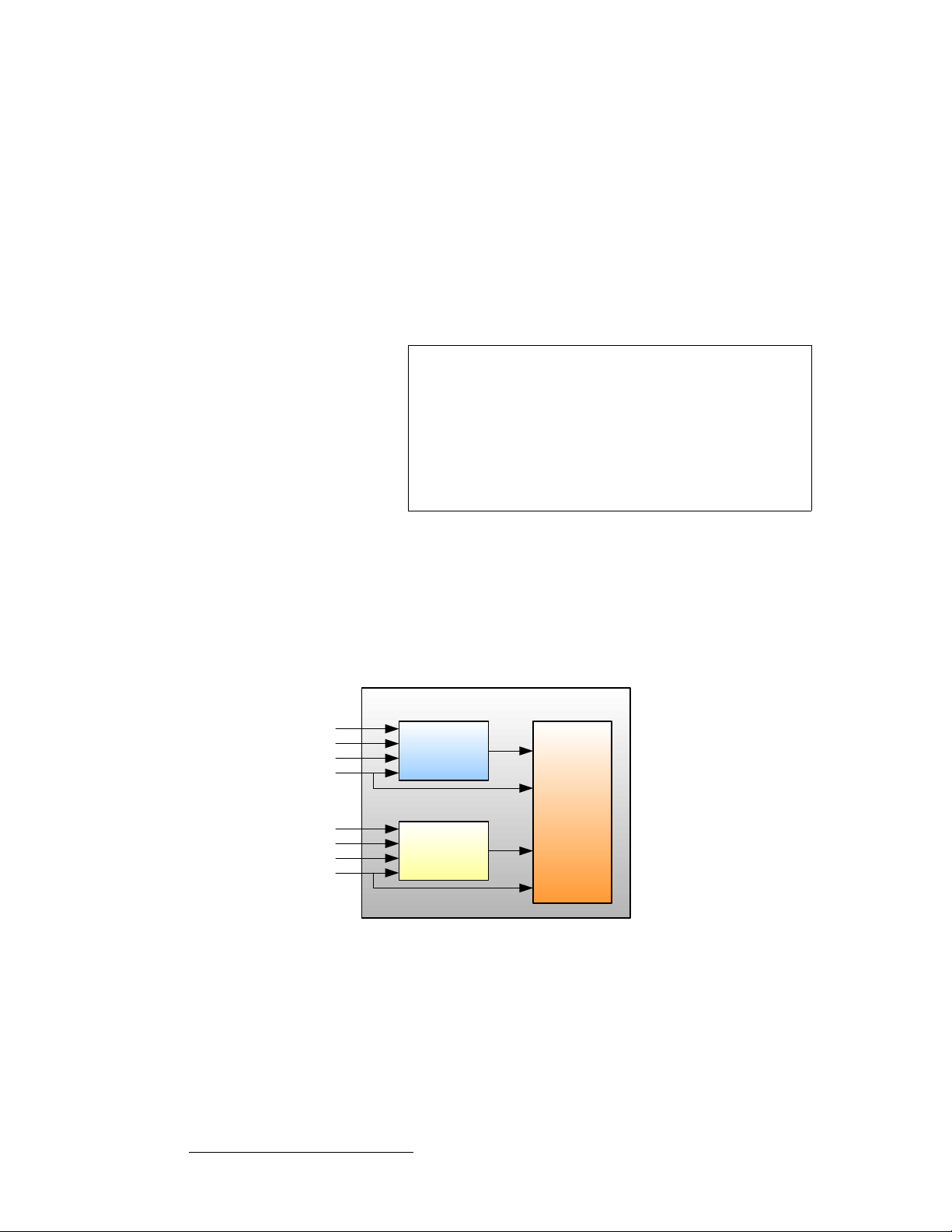
fеймн=cдЙсбДбдбну
Each M/E board provides two independent Athena scalers with universal inputs that handle
both analog and digital video sources.
The figure below illustrates a block diagram of the VP’s M/E.
VP M/E Board
Source Link
Analog
HD/SDI
DVI
Source Link
Analog
HD/SDI
DVI
Scaler A
Background Channel
Mixer
Scaler B
Background Channel
Figure 1-2. M/E Board Block Diagram, VP
The VP accepts the following inputs:
• Standard component and composite analog video formats (NTSC, PAL, SECAM)
• SDI video
• Computer input resolutions up to 1920 x 1200 (analog or digital)
• Analog HD formats including 720p, 1080I, 1080p
• HD-SDI Video
24 Encore Presentation System • User’s Guide • Rev 04
Page 25
• 2048 x 1080p Digital Cinema video
• Plasma display resolutions
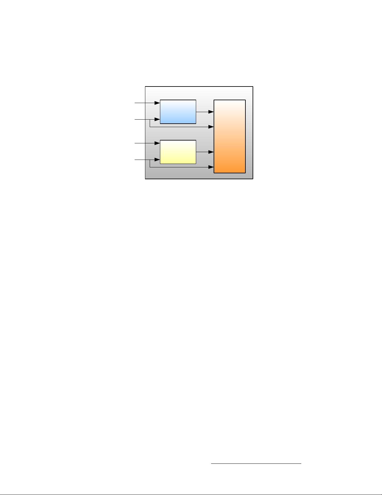
The figure below illustrates a block diagram of the VPx’s M/E.
VPx M/E Board
Source Link
Scaler A
DVI
Background Channel
Mixer
Source Link
Scaler B
DVI
Background Channel
Figure 1-3. M/E Board Block Diagram, VPx
The VPx accepts the following inputs:
• Computer input resolutions up to 1920 x 1200, via DVI
NK==fенкзЗмЕнбзе
System Overview
pЕ~дбеЦ=~еЗ=hЙубеЦ
For both Processor models, the Athena scaler features the followi ng:
• 1:1 pixel sampling
• Motion adaptive de-interlacing for both standard and high definition sources
• 3:2 and 2:2 pull down detection
• Aspect ratio correction and image cropping
• Real-time window resizing and positioning
• Full support for seamless transitions, window borders, drop shadows and keying
lмнймн=cдЙсбДбдбну
Each Encore VP and VPx incorporates one output board, which provides all output
interface functions as well as the blending and data-doubling functions required to support
wide screen applications. Supported output resolutions include:
• Computer output resolutions up to 1600 x 1200
• Analog HDTV resolutions including 720p, 1080I, 1080p
• HD-SDI video
• 2048 x 1080p digital cinema video
• Plasma display resolutions.
Output synchronization is supported to lock the output frame rate to an externally applied
NTSC/PAL black burst signal.
Encore Presentation System • User’s Guide • Rev 04 25
Page 26
NK==fенкзЗмЕнбзе
System Overview
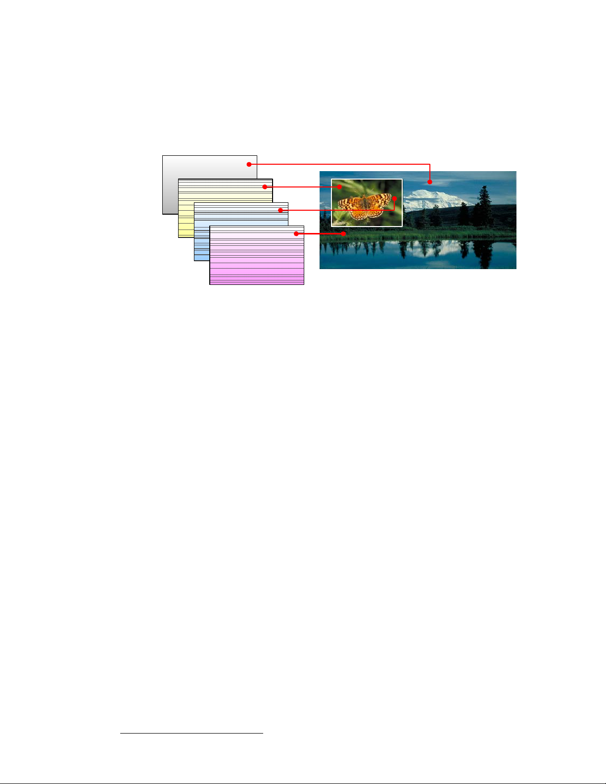
^=tçêÇ=^Äçìí=i~óÉêë
Within the Encore system, each mixer has two layers, A and B, and each can be assigned
to either PIP or Key functionality.
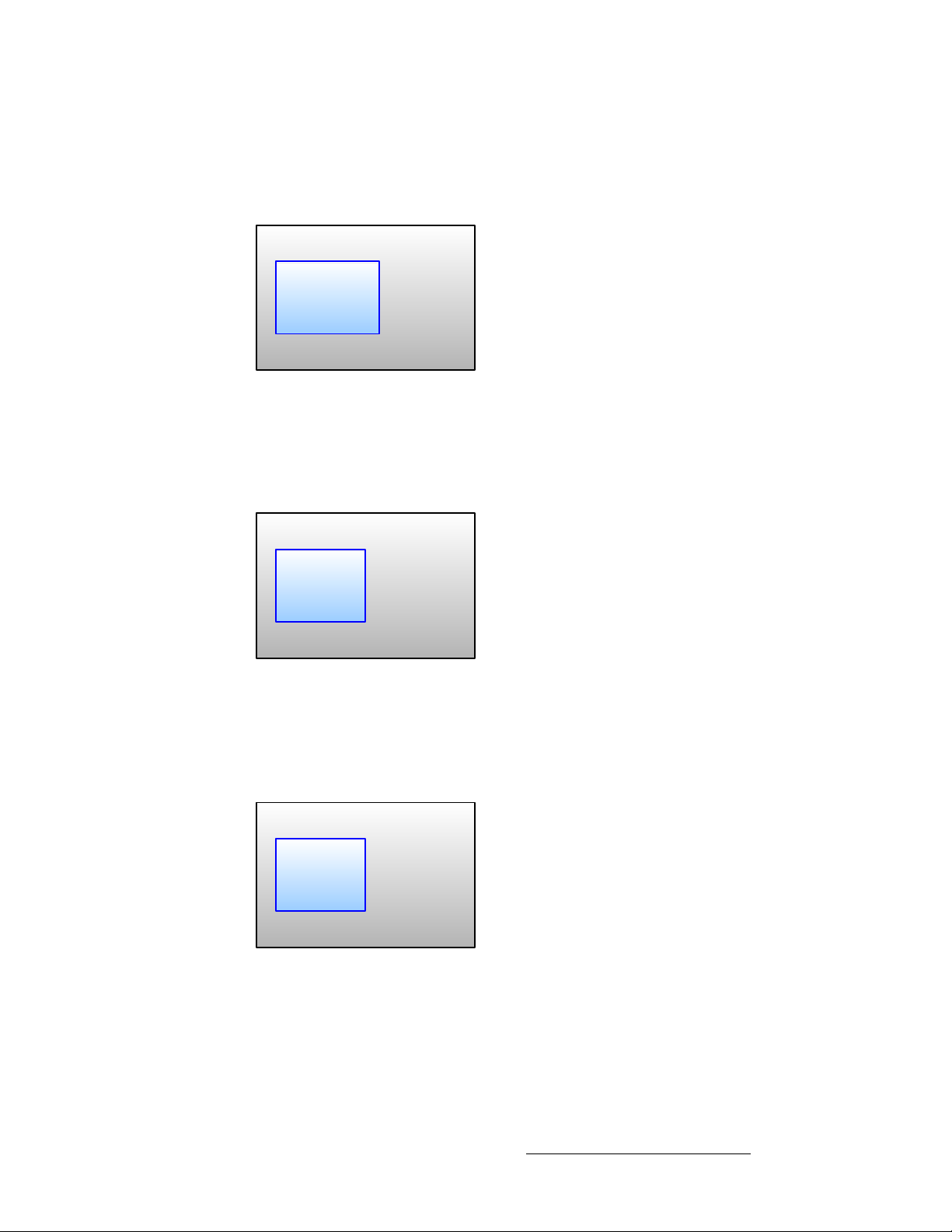
A typical single mixer application (including the DSK) is illustrated below.
Background
Layer A: PIP
Nature
Layer B: Key
DSK
Figure 1-4. Layer Illustration — Background, Single Mixer + DSK
Please note the following important points:
• The Downstream Key (DSK) is the highest priority layer, using an unscaled DVI
input or a scaled frame grab. The DSK visually appears over all other images
(PIPs and keys) on all mixers.
• The high resolution Background layer has the lowest priority, using an unscaled
DVI input or a scaled frame grab. This layer visually appears behind all other
PIPs, keys, and the DSK. The system can transition between two background
sources — both of which must be at the projector’s native resolution.
• On any mixer, a PIP layer appears over backgrounds and under the DSK. Effects
include mixes and wipes, smooth moves and resizing, adjustable aspect ratio,
borders, drop shadows and soft edges, and PIP “clone” mode (mirror and offset).
• On any mixer, a Key layer also appears over backgrounds and under the DSK.
Key effects include luminance keys, split keys (key alpha and fill), invert keys and
color keys (graphics).
• Within a single mixer, layer B has priority over layer A, but you can change that
priority as desired by pressing the Swap Z-Order button.
• On a triple mixer system, up to six inputs can be scaled to produce PIP or Key
images that can be transitioned independently or in pairs.
Wilderness
26 Encore Presentation System • User’s Guide • Rev 04
Page 27

• Between mixers, the hierarchy of priorities is easy:
Background
M/E 1 (Mixer 1)
M/E 2 (Mixer 2)
M/E 3 (Mixer 3)
DSK
Figure 1-5. Mixer Priority
~ The Background layer is always at the bottom.
~ All effects on Mixer 1 are visually in front of the background.
~ All effects on Mixer 2 are in front of Mixer 1.
~ All effects on Mixer 3 are in front of Mixers 1 and 2.
~ The DSK is visually in front of Mixers 1, 2, 3 and background.
NK==fенкзЗмЕнбзе
System Overview
^=tзкЗ=^Дзмн=aЙлнбе~нбзел
The Encore Presentation System offers complete flexibility with regard to destinations.
Examples of each destination “type” are listed below:
• Single Screen Destination — this is a “single projector” destination that takes its
input from a VP. A VPx can only be used as a single destination in a special
widescreen “preview” configuration.
• Wide Screen Destination — this is a “multiple projector” destination that takes its
inputs from two (or more) VP or VPx units.
• ScreenPRO-II Destination — this is a standalone ScreenPRO-II that takes its
inputs via direct connections or routers. When the ScreenPRO-II output is
connected to a “side” projector (or monitor), its “look” can be controlled from the
Encore Controller as a unique destination.
• Aux Destination — this is a monitor that takes its input from a router output (in a
single format). When you select an Aux destination and a source on the
Controller, you are talking directly to a router output via RS-232 or Ethernet
communications — and making the selected source-to-destination connection.
• ImagePRO Aux Destination — this is an ImagePRO that takes its input(s) from
multiple routers in multiple formats. When connected to a monitor or projector, a
scaled signal is provided in one format. Whereas an Aux Destination’s input is
single format, an ImagePRO Aux Destination’s input is multi-format.
• PresentationPRO-II Aux Destination — this is a PresentationPRO-II that takes
its input(s) from up to two routers — one analog and one SDI. When connected to
a single monitor or projector, a scaled signal is provided in one format. The
transition “type” between sources is selected on the PresentationPRO-II itself.
In Chapter 6, refer to the “Destination Setup
destination setup procedures. Refer to the “AUX Destination Setup
for details on Aux destination setup procedures.
” section on page 277 for details on standard
” section on page 281
Encore Presentation System • User’s Guide • Rev 04 27
Page 28

NK==fенкзЗмЕнбзе
System Overview
bССЙЕн=`згДбе~нбзел
A fully-loaded Encore VP or VPx is a unit with three mixer (M/E) boards. A unit configured
in this way can scale six input sources to create PIPs and/or Keys. These in turn can be
sized and positioned on the screen in real-time.
This section illustrates the many (but not all) combinations of image effects that you can
create on 1, 2 and 3 mixer systems. Please note:
The following topics are discussed:
pбеЦдЙ=jбсЙк=bССЙЕнл
• In the following illustrations, the specific layers used in creating each effect are
labeled (e.g.,
Mixer 1,
PIP 1A, PIP 1B). For example, 1A denotes the first PIP or key on
1B denotes the second PIP or key on Mixer 1, etc.
• The symbol ↔ denotes a PIP or a key that can transition. For example, PIP 2A
↔ 2B indicates that you can dissolve between sources within the PIP.
• Single Mixer Effects
• Dual Mixer Effects
• Triple Mixer Effects
A single Mixer Encore system provides two backgrounds, two scalable layers in the Mixer
plus an unscaled DSK. Please note:
• If the DSK is in use, the background cannot transition between A and B — it’s all a
matter of “available resources.”
• The DSK and backgrounds are unscaled, in all cases.
In Chapter 7, refer to the “
information.
A Word About Resources” section on page 345 for additional
• Single Mixer Effect 1
This effect includes a non-transitioning background (either A or B), one
transitioning PIP and the DSK.
Background
PIP
1A ↔ 1B
DSK
Figure 1-6. Single Mixer Effect 1 Diagram
28 Encore Presentation System • User’s Guide • Rev 04
Page 29
NK==fенкзЗмЕнбзе
System Overview
• Single Mixer Effect 2
This transition is similar to effect 1, but because the DSK is not in use, the
background can transition from source A to B, and the PIP can transition between
layers A and B.
Background A ↔ B
PIP
1A ↔ 1B
Figure 1-7. Single Mixer Effect 2 Diagram
• Single Mixer Effect 3
In this effect, because the DSK is in use, the background cannot transition. Here,
you can independently fade (or cut) one scaled PIP and one scaled key, with
complete size and position flexibility.
Background
PIP
Key 1B
1A
DSK
Figure 1-8. Single Mixer Effect 3 Diagram
• Single Mixer Effect 4
This transition is similar to effect 3, but because the DSK is not in use, the
background can transition between sources A and B. Y ou can also independently
fade, cut, size and position both the PIP and the key.
Background A ↔ B
PIP
Key 1B
1A
Figure 1-9. Single Mixer Effect 4 Diagram
Encore Presentation System • User’s Guide • Rev 04 29
Page 30

NK==fенкзЗмЕнбзе
System Overview
• Single Mixer Effect 5
In this effect, because the DSK is in use, the background cannot transition — you
can use either A or B. Here, you can independently fade two scaled PIPs up and
down — with or without the DSK on screen.
Background
PIP
1A
PIP
1B
DSK
Figure 1-10. Single Mixer Effect 5 Diagram
• Single Mixer Effect 6
This transition is similar to effect 5, but because the DSK is not in use, the
background can transition. You can also independently fade the two PIPs.
Background A ↔ B
PIP
1A
Figure 1-11. Single Mixer Effect 6 Diagram
aм~д=jбсЙк=bССЙЕнл
PIP
1B
A dual Mixer Encore system provides two backgrounds, a total of four scalable layers in the
two Mixers, plus an unscaled DSK.
• Dual Mixer Effect 1
Using the capabilities of two Mixers, this effect enables you to transition
backgrounds, in addition to transitioning the PIPs on both Mixer 1 and 2 — with or
without the DSK on screen.
Background A ↔ B
PIP
1A ↔ 1B
PIP
2A ↔ 2B
DSK
Figure 1-12. Dual Mixer Effect 1
30 Encore Presentation System • User’s Guide • Rev 04
Page 31

NK==fенкзЗмЕнбзе
System Overview
• Dual Mixer Effect 2
With this dual Mixer effect, you can transition backgrounds between sou rces A
and B, plus independently size, position, cut or fade a PIP and key on each Mixer.
Transitions within the PIPs cannot be performed. The DSK can be used without
restriction.
Background A ↔ B
PIP
1A
PIP
2A
Key 1B Key 2B
DSK
Figure 1-13. Dual Mixer Effect 2
• Dual Mixer Effect 3
This effect enables you to transition between backgrounds, and size/position four
PIPs on screen — with or without the DSK. In addition, any PIP could be
substituted for a key, but transitions within a PIP (or transitions between keys)
cannot be performed.
Background A ↔ B
PIP 1A
PIP 1B
PIP 2A
PIP 2B
DSK
Figure 1-14. Dual Mixer Effect 3
qкбйдЙ=jбсЙк=bССЙЕнл
A triple Mixer Encore system provides two backgrounds, a total of six scalable layers in the
three Mixers plus an unscaled DSK.
• Triple Mixer Effect 1
With this three Mixer effect, you can transition between backgrounds, fade or cut
the DSK as desired, and independently transition within three PIPs.
Background A ↔ B
PIP
1A ↔ 1B
PIP
2A ↔ 2B
PIP
3A ↔ 3B
DSK
Figure 1-15. Triple Mixer Effect 1
Encore Presentation System • User’s Guide • Rev 04 31
Page 32

NK==fенкзЗмЕнбзе
System Overview
• Triple Mixer Effect 2
This effect enables you to transition between backgrounds sources, plus
independently size, position, cut or fade a PIP and key on each of the three
Mixers. Transitions within the PIPs or transitions between keys cannot be
performed.
Background A ↔ B
PIP 1A
Key 1B
PIP 2A
PIP 3A
Key 3B
Key 2B
DSK
Figure 1-16. Triple Mixer Effect 2
• Triple Mixer Effect 3
Here, you can transition between backgrounds, and size/position six PIPs on
screen — with or without the DSK. Any PIP can be substituted for a key, but
transitions within PIPs (or transitions between keys) cannot be performed.
Background A ↔ B
PIP
1B
PIP
2A
PIP
3B
PIP 2B
PIP
3A
PIP
1A
DSK
Figure 1-17. Triple Mixer Effect 3
fенЙЦк~нбзе=пбнЬ=pбЦе~д=oзмнЙкл
The use of high quality routers (routing switchers) is an integral part of the Encore system.
Barco offers a complete line of routers for use with Encore, including models in analog,
SDI, HD/SDI and DVI formats. All of our routers are designed and tested to ensure quality,
reliability, and ease of use.
Encore is also compatible with other manufacturers' routers. In Chapter 5, refer to the
“
Router Specification Menu” section on page 190 fo r details.
bоЙен=j~е~ЦЙгЙен
The Encore Presentation System is compatible with Barco Events Manager software,
which complements Encore’s real-time control by supporting enhanced external device
control and sophisticated pre-programmed sequences. Please note:
• Barco Events Manager treats Encore as a peripheral device and sends
commands to the controller to execute timeline programmed sequences. Thi s
allows Encore’s functions to be fully integrated with other show effects.
• Because there is bi-directional communications between Barco Events Manager
and Encore, the Encore system can also trigger the Events Manager software.
32 Encore Presentation System • User’s Guide • Rev 04
Page 33

NK==fенкзЗмЕнбзе
System Overview
• The range of external devices that can be controlled is greatly increased,
permitting users to automate entire shows. The Events Manager software also
supports the management of digital media sources.
`зеСбЦмк~нбзе=^ййдбЕ~нбзел
Two configuration applications are available to assist with system setup, backup and
restore functions.
• Encore Configurator
• Barco Backup and Restore Utility
bеЕзкЙ=`зеСбЦмк~нзк
The Encore Configurator enables you to create basic Encore system setups offline.
Using the Configurator, you can define wide and single screen parameters, router patching,
basic input setup and basic destination setup. Once complete, the “configuration” can be
sent to the Controller, saving overall setup time. The application also enables you to
remotely access the Encore Configuration Loader.
_~кЕз=_~Евмй=~еЗ=oЙлнзкЙ=rнбдбну=
The Barco Backup and Restore Utility enables you to perform complete system backup
and restore operations to a PC (or laptop) connected via Ethernet. Backup and restore
functions include the Controller, the VP(s) and the VPx(s).
Encore Presentation System • User’s Guide • Rev 04 33
Page 34

NK==fенкзЗмЕнбзе
System Overview
mкзЗмЕн=aбССЙкЙенб~нбзе
The table below illustrates the differences between the small (SC) and large (LC) Encore
controllers.
Table 1-1. Product differentiation between SC and LC controllers
Feature Small Controller (SC) Large Controller (LC)
Encore VP and VPx supported 32 32
Wide screen support Yes Yes
External router control Yes Yes
Inputs supported 24 64
Destinations supported 6 32
Available presets 64 900
Layers supported 1 DSK
6 Scaled Inputs (PIP or Key)
1 Transitioning background
User-selectable transitions Yes Yes
Available groups 4 8
Available user-definable keys None 100
Joystick and T-Bar Yes Yes
320 x 240 graphic displays 1 2
Light sticks 2 3
PS/2 keyboard support Yes Yes
Communication Ethernet, RS-232 Ethernet, RS-232
Program sequencing Yes Yes
Field upgradable Yes Yes
Ethernet control interfaces Yes Yes
Tally support 8 8
1 DSK
12 Scaled Inputs (PIP or Key)
1 Transitioning background
34 Encore Presentation System • User’s Guide • Rev 04
Page 35

kЙп=cЙ~нмкЙ=oЙобЙп
This section lists the new features that have been implemented in recent versions of
Encore software. Reference links are provided.
• Software Version 1.24 Features
• Software Version 1.22 Features
• Software Version 1.19 Features
pзСнп~кЙ=sЙклбзе=NKOQ=cЙ~нмкЙл
The following new features have been implemented in software version 1.24.
• Stacked Configuration Support
Stacked configuration support has been added to the Encore Controller SC.
~ In Chapter 3, refer to the “Single Screen Stack Configuration” section
~ In Chapter 6, refer to the “Standard and Stack Destination Setup”
• Feature Enhancements
The following feature and interface enhancements are provided in the version:
~ ImagePRO AUX transitions are now smooth when switching between
~ For analog NTSC and PAL inputs, the default sync slice is now 80mV.
~ Support has been added for Grass Valley native protocol.
~ Programmable DVI output sync polarity adjustments have been added.
~ The following input and output resolutions have been added:
NK==fенкзЗмЕнбзе
New Feature Review
on page 80 for instructions on installing single screen stack
configurations, and the “
page 84 for instructions on wide screen stack configurations.
section on page 277 for stack setup instructions.
any inputs routed to an ImagePRO. This feature requires ImagePRO
software 2.43 or higher.
This change improves the system’s ability to maintain a stable lock to
video sources where signal integrity is less than ideal.
In Chapter 5, refer to the “
• 1280x720 @60
• 1280x720 II @60
• 1280x800 @60
• 1280x800 II @60
• 1360x768 @60
• 1440x900 @60, @75, @85
• 1680x1050 @60
• 1920x1080pSF @29.97, @30
• 1920x1200 @50, @59.94, @60
• 2048x1200 @59.94
In Appendix A, refer to the “
page 375 for a complete list of all input and output resolutions.
Wide Screen Stack Configuration” section on
Settings Menu” section on page 165.
Input and Output Resolutions” section on
Encore Presentation System • User’s Guide • Rev 04 35
Page 36

NK==fенкзЗмЕнбзе
New Feature Review
pзСнп~кЙ=sЙклбзе=NKOO=cЙ~нмкЙл
The following features were implemented in software version 1.22.
• Vertical Blending
Vertical Array blending is supported, and all cabling to the VP and VPx is the
same as a standard widescreen setup. In Chapter 6, refer to the “
Setup” section on page 278 for instructions.
Vertical Blend
• ScreenPRO-II EOC Support
When a ScreenPRO-II is used as a destination, Encore supports the Enhanced
Output Card (EOC) option of the ScreenPRO-II. This option is a factory installed
card that provides additional output formats, and expands the unit’s still store
capabilities. In Chapter 6, refer to the “
page 280 for instructions.
ScreenPRO-II with EOC” section on
• Enhanced ScreenPRO-II Routing
When a ScreenPRO-II is used as a destination, Encore supports the internal and
external routing capability of the ScreenPRO-II. In Chapter 6, refer to the
“
ScreenPRO-II Destination Setup” section on page 279 for details.
• Input Auto Acquire
By default, the Controller attempts to Auto Acquire an input as soon as the source
is selected, provided it does not currently have a saved input config file. In
Chapter 5, refer to the “
User Preference Menu” section on page 204 for details.
• Custom Borders
In the Border Menu, the Custom Border Menu enables you to select any preconfigured border style as a starting point, and then configure a custom border
from a variety of parameters. In Chapter5, refer to the “
page 218 for details.
Border Menu” section on
• Preset Recall Options
From the Home Menu, the Preset Recall Menu enables you to select from a
variety of preset recall options. In Chapter 5, refer to the “
Menu” section on page 208 for details.
Preset Recall Options
• Mix, User Effect and User Trans Buttons
In the Transition Functions sections on both controllers, the Mix, User Effect
and
User Trans (1, 2, and 3) buttons have been implemented. In Chapter 4, refer
to the “
Transition Functions Section” heading on page 142 for details.
• Patch Next
On the Output Patch Menu, the {P ATCH NEXT} soft key enables you to enter
output patch data quickly, provided that the physical output connections to the VP
and VPx units have been performed logically. In Chapter 5, refer to the “
Patch Menu” section on page 194 for details.
• Previous Button
In the Preset Section, the Previous button has been implemented. In Chapter 4,
refer to the “
Preset Section” heading on page 123 for details.
• New Routers Supported
Routers from FSR, AutoPatch and NVision are supported. In Chapter 5, refer to
the “
Router Specification Menu” section on page 190 fo r details.
Output
36 Encore Presentation System • User’s Guide • Rev 04
Page 37

NK==fенкзЗмЕнбзе
New Feature Review
• Enhanced Source Preview
The Source Preview function has been enhanced. After the button has been
pushed for the first time, the next press sizes the PIP to 1:1, with respect to the
source’s input resolution. In Chapter 7, refer to the “
section on page 333 for details.
• 900 Presets Fully Active
All Presets starting with Page 15, Preset 1 (and above) can be saved, provided
that an MMC or MMCPlus card (512MB or larger) is installed in the Controller’s
Multi-media card slot. In Chapter 7, refer to the “
on page 345 for details.
• Enhanced Events Manager Support
Based on the support of 900 Presets, the "Events Manager Support" function on
User Preference Menu addresses a Preset Recall issue, when more than
the
500 Presets are saved in the Controller. In Chapter 5, refer to the “
Preference Menu” section on page 204 for details.
• Widescreen Menu Shortcuts
New shortcuts have been added between the Test Pattern Menu and the
Widescreen Menu. In Chapter 5, refer to the “Test Pattern Menu” section on
page 166 for details.
• Stacked Configuration Frame Grab
When Encore is functioning in a stacked configuration, Frame Grab captures have
been disabled on the bottom M/E board of the top VP or VPx. This change is
required because the background channels of the M/E board are in use to
facilitate the transfer of data between processors. In Chapter 7, refer to the
“
Working with Frame Grabs” section on page 355 for details.
• Numeric PIP Entry
On the Large Controller, numeric entry of PIP size and position has been
enhanced to allow you to enter numbers up to 8 digits in length. In Chapter 7,
refer to the “
Using the Alphanumeric Keypad” section on page 310 for details.
• Joystick and T-Bar Calibration
New tools are provided for calibrating the Joystick and T-Bar. In Chapter 5, refer
Diagnostics Setup Menu” section on page 177 for details.
to the “
• VPx
Support is provided for the VPx, a new processor with a reduced set of input
circuits, for use in widescreen configurations, and special widescreen “preview”
configurations. Refer to Chapter 2, “
Hardware Orientation” on page 43.
Using Source Preview”
Working with Presets” section
User
Note
Software version 1.22 (or later) is required for VPx control.
• Encore GC
Support is provided for the Encore GC, a graphical user interface (GUI) designed
to control the Encore and ScreenPRO-II processors without the need for an
Encore LC or SC. The system also includes the ECU (Encore Control Unit), an
advanced server that connects video processors, routers, and the PC (which runs
the Encore GC) together. Refer to the “
Encore Presentation System • User’s Guide • Rev 04 37
Encore GC User’s Guide” for details.
Page 38

NK==fенкзЗмЕнбзе
New Feature Review
pзСнп~кЙ=sЙклбзе=NKNV=cЙ~нмкЙл
The following features were implemented in software version 1.19.
• Support for Lantronix UDS2100
Support is provided for the Lantronix UDS2100, a serial-to-Et hernet device that
replaces the
continue to be supported by Encore. In Chapter 3, refer to the “
section on page 64 for details on using the Lantronix to connect two (or more)
serial routers to Encore.
UDS200 — which Lantronix is phasing out. Both models will
Installation”
• Wide Screen Preview Configuration
Instructions are provided for configuring a system with a fourth VP or VPx, which
is then used to create a combined wide screen program/preview display. In
Chapter 3, refer to the “
section on page 76 for details.
Wide Screen Configuration Plus Wide Screen Preview”
• Live Switch Modes
Two Live Switch modes are available:
~ The Live Switch "Source" mode turns both rows of the Source
Selection Bus
“
Using Live Switch Source Mode” section on page 341.
into a live “Program” bus. In Chapter 7, refer to the
~ The Live Switch "Program/Preview" mode turns both rows of the
Source Selection Bus into a live “Program/Preview” bus. The top row
acts as
see the “
page 340 for details.
Program, and the bottom row acts as Preview. In Chapter 7,
Using Live Switch Program/Preview Mode” section on
• Tally Mapping
Using the Input Patch menu, you can assign any of the eight available tallies to
any input source. In Chapter 5, refer to the “
on page 188 for details.
Input Source Patch Menu” section
• Invalid Video and LOS
New methods have been implemented to handle invalid video signals and LOS
(loss of video) conditions. In Chapter 5, refer to the “
section on page 204, and in Chapter 7, refer to the “
on page 308 for details.
User Preference Menu”
A Word About LOS” section
• Wide Screen Definition Flexibility
Y ou can create wide screen destinations using VP or VPx units that do not contain
the same number of M/E boards. In Chapter 6, refer to the “
section on page 277 for details.
Destination Setup”
• Frame Grabs
The Frame Grab button accesses the Frame Grab Menu, which enables you to
store up to 100 frames. Frames can be captured from any layer (including the
Background and DSK), for use on Program in either the Background or DSK
channels. In Chapter 7, refer to the “
page 355 for details.
Working with Frame Grabs” section on
• Destination Flexibility
The Encore system offers comprehensive destination flexibility. In addition to
standard single screen and wide screen destinations, you can configure
ScreenPRO-II units as destinations, plus three types of Aux destinations:
38 Encore Presentation System • User’s Guide • Rev 04
Page 39

NK==fенкзЗмЕнбзе
New Feature Review
standard Aux (monitors), ImagePRO Aux and PresentationPRO-II Aux. Refer
to Appendix D, “
• Support for VP or VPx IDs 17 - 32
Using the Miscellaneous Menu, you can re-define VP or VPx IDs using numbers
17 - 32. Only processors that are
defined. In Chapter 5, refer to the “
for details.
• External Trigger Function
When Encore is used in conjunction with Barco Events Manager, the following
functionality is provided:
~ Timeline tasks can be triggered when specific Presets are recalled.
~ Playback of a paused timeline can be resumed (using Ext Trigger).
In Chapter 7, refer to the “
• Wide Screen Link Diagnostics
The Diagnostics Menu contains a {LINKS} softkey that accesses the Wide
Screen Link Diagnostics Menu. This menu enables you to test the Program and
Source link cables that are required for wide screen operation. In Chapter 5, refer
to the “
Diagnostics Setup Menu” section on page 177.
• Third Party Router Support
Additional third party routers are supported in the Encore Controller. In Chapter 5,
refer to the “
• Copy Function
The copy function enables you to copy PIP and Key parameters between mixers.
In Chapter 7, refer to the “
• Downstream Key (DSK)
Encore’s DSK function enables you to use an unscaled DVI source or a scaled
frame grab as the downstream key. The
either a Luma or Color DSK. In Chapter 7, refer to the “
on page 326 for details.
• Color Keying using the Color Picker
Color Keying enables you to key off a color instead of a luminance value. The
color can be selected via RGB parameters or by using the “
In Chapter 7, refer to the “
• Keyframe Effects for Moves
Numerous predefined keyframe effects are available for “moves,” including linear,
linear accelerations, arches and boomerangs motion types. In Chapter 7, refer to
the “
Using Move” section on page 336 for details.
• Clone Function
For wide screen configurations (only), the Clone function enables you to clone a
PIP or a Key on a particular M/E, creating a copy of the effect on the opposite
screen. All attributes are cloned, including size, source, border and shadow. In
Chapter 7, refer to the “
• LCD Calibration
The LCD calibration function improves the accuracy of the Touch Screens. In
Chapter 7, refer to the “
Working With Destinations” on page 393 for details.
not currently defined as destinations can b e re-
Miscellaneous Menu” section on page 196
Using Ext Trigg e r” section on page 333 for details.
Router Specification Menu” section on page 190 for details.
Using Copy” section on page 331 for details.
DSK Setup Menu allows you to set up
Modifying Keys” section
Pick Color” feature.
Modifying Keys” section on page 32 6 for details.
Using Clone” section on page 330 for details.
Touch Scre en Calibration” section on page 305.
Encore Presentation System • User’s Guide • Rev 04 39
Page 40

NK==fенкзЗмЕнбзе
New Feature Review
• Support for Analog Backgrounds
Using the Background Input Setup Menu, you can choose between Analog, DVI
Matte and “frame grab” backgrounds. In Chapter 5, refer to the “
Input Setup Menu” section on page 237 for details.
Background
• Support for Two Separate Matte Colors
Two separate matte colors can be defined, one for BG A and one for BG B. In
Chapter 5, refer to the “
page 240 for details.
Background Menu Functions — Matt e Type” section on
• EDID
The EDID (Extended Display Identification Data) programming procedure is a
prerequisite for background and DSK setup. The procedure guarantees proper
communications at the preferred resolution between Encore’s DVI inputs and your
external equipment. In Chapter 6, refer to the “
page 268 for details.
Programming EDID” section on
• User Keys
On the Controller LC, User Keys are available when you press User Copy. This
action accesses the
(or a portion) of the current effect’s attributes, such as border color, PIP size,
aspect ratio, etc. In Chapter 7, refer to the “
page 350 for instructions.
User Key Copy Setup Menu, which enables you to select all
Working with User Keys” section on
• Group Buttons
All Group buttons operate with “toggle” funct i onality rather than “additive”
functionality. In Chapter 7, refer to the “
page 312 for instructions.
Working with Groups” section on
• Layer Join Mode
The “Join” mode enables you to create a fixed relationship between a mixer’s two
layers. Whenever the mixer is selected, the two joined layers move as one. In
Chapter 7, refer to the “
Using Join Mode” section on page 335 for instructions .
• Key Cut and Fill
The “Key Cut and Fill” function enables you to cut a key in Layer B and fill it with
video from Layer A — within the same Mixer. The two Layers can be
manipulated independently or joined using the “Join” function. In Chapter 7, refer
to the “
Using Cut & Fill” section on page 325 for instructions.
• Source Preview
For any selected Layer, press Source Preview in the Layer Functions Section
to quickly focus or “isolate” that layer for sizing and adjustment purposes in
Preview only. In Chapter 7, refer to the “
page 333 for instructions.
Using Source Preview” section on
• Alphanumeric Keypad
On the Controller LC only, the Alphanumeric Keypad enables you to enter and
change numeric fields without having to use a rotary knob. In Chapter 7, refer to
the “
Using the Alphanumeric Keypad” section on page 310 for instructions.
• PS/2 Keyboard
Standard PS/2 style keyboards can be used with both Controllers for numeric
entry and “naming” of certain functions (such as frame grabs). In Chapter 7, refer
to the “
Using the PS/2 Keyboard” section on page 311 for details.
40 Encore Presentation System • User’s Guide • Rev 04
Page 41

NK==fенкзЗмЕнбзе
New Feature Review
• Programmable Controller Lockout
You can lock the Controller, thus preventing key presses from changing the
system. While locked, serial commands can still be sent via the Console Port. To
unlock the Controller, a lockout code is required. In Chapter 7, refer to the
“
Enable/Disable Controller Lockout” section on page 352 for instructions.
• Destination Based Effects Menu
The Effects Menu allows you to modify and manage effects on a destination-bydestination basis, including the ability to define key frames, transition rates, paths
and effect properties. In Chapter 5, refer to the “
page 209 for details.
• Programmable Raster Box Size
In the Settings Menu, users can adjust the size of the raster box that surrounds
PIPs and Keys — on a destination by destination basis. In Chapter 5, refer to the
“
Settings Menu” section on page 165 for details.
• Flicker Reduction for Interlaced Formats
When using Encore to output an interlaced format, a Flicker Reduce label
appears in the
reduction) through 20 (maximum reduction). In Chapter 5, refer to the “
Menu” section on page 165 for details.
Settings Menu. The range is OFF (no reduction) or 1 (minimum
• Output Formats
Additional output formats are available. In Appendix A, refer to the “Input and
Output Resolutions” section on page 375 for details.
• VP or VPx Stacking
“Stacking” is a configuration method that provides access to six mixers, with the
ability to display up to 12 PIPs simultaneously. VP or VPx units can be st acked in
single or wide screen configurations, and Controller operations are identical to
“non-stacked” systems. Stacking is only available with the Controller LC. In
Chapter 3, refer to the “
refer to the “
Destination Setup” section on page 277 for setup details.
Installation” section on page 64 for details. In Chapter 6,
Effects Menu” section on
Settings
Encore Presentation System • User’s Guide • Rev 04 41
Page 42

NK==fенкзЗмЕнбзе
New Feature Review
42 Encore Presentation System • User’s Guide • Rev 04
Page 43

OK==e~кЗп~кЙ=lкбЙен~нбзе
få=qÜáë=`Ü~éíÉê
This chapter provides detailed information about Encore’s hardware, including the Video
Processor, VPx, and the Controller (rear panel only).
The following topics are discussed:
• Video Processors
• M/E Input Notes
• Program Output Notes
• Analog Input Flexibility
• Controller Rear Panels
Note
Once you have reviewed all of the sections in this chapter,
please continue with Chapter 3, “
page 61.
Hardware Installation” on
Encore Presentation System • User’s Guide • Rev 04 43
Page 44

2. Hardware Orientation
Video Processors
sбЗЙз=mкзЕЙллзкл
The following topics are discussed in this section:
• Video Processor Front Panel
• VPx Front Panel
• Video Processor Rear Panel
• VPx Rear Panel
• A Word About M/E Connector Priority
• M/E Connectors (VP)
• M/E Connectors (VPx)
sбЗЙз=mкзЕЙллзк=cкзен=m~еЙд
The figure below illustrates the Video Processor (VP) front panel:
2 31
Visibly yours
Folsom
ENCORE
Figure 2-1. VP Front Panel
1) Chassis Handles 2) Air Intake Ports 3) Status LED
Following are descriptions of each front panel control feature:
1) Chassis Handles
Two Chassis Handles are provided for ease of installation and transportation.
When transporting the chassis by its handles,
connectors towards the ground. If you do, you may damage the rear connectors.
2) Air Intake Ports
Two Air Intake Ports are provided for chassis cooling. The direction of airflow is
from the front to the rear. To prevent overheating, do not block the air intake ports.
3) Status LED
The Status LED, behind the right-hand Air Intake Port, indicates the following:
do not set it down with the rear
~ Solid Red: the unit is initializing
~ Solid Green: the unit is ready for use
~ Blinking Red: an error has occurred
44 Encore Presentation System • User’s Guide • Rev 04
Page 45
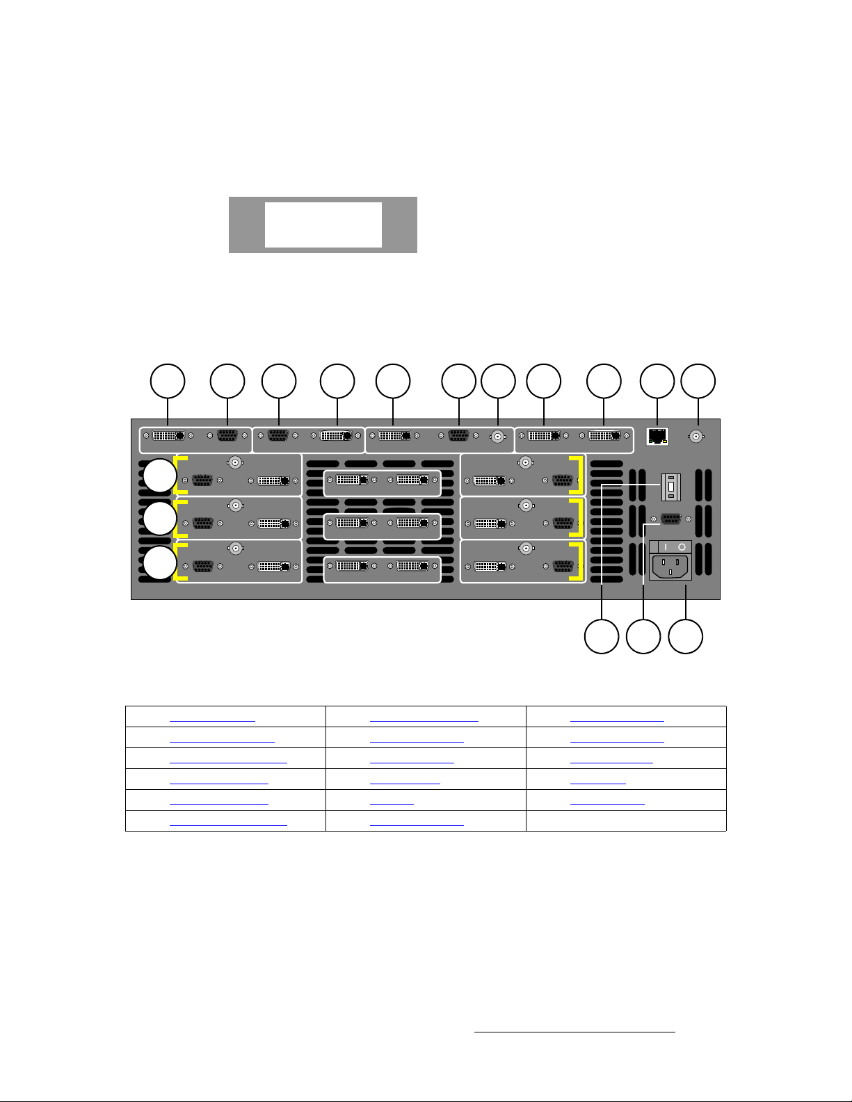
2. Hardware Orientation
Video Processors
smñ=cêçåí=m~åÉä
The VPx front panel is identical to the “standard” VP front panel, with the exception of the
VPx product label, as shown below:
Folsom
ENCORE
VPx
Figure 2-2. VPx label
sбЗЙз=mкзЕЙллзк=oЙ~к=m~еЙд
The figure below illustrates the VP rear panel:
1
DVI PREVIEW ANALOG
12
13
14
2 3 4 5 6 7 8 9 10 11
Hol
es
ANALOG
Hol
es
ANALOG
Hol
es
ANALOG
Hol
es
HD / SDI
INPUT 1A
HD / SDI
INPUT 2A
HD / SDI
INPUT 3A
Hol
es
ANALOG PROGRAM 2 DVI
DVI
DVI
DVI
DVI PROGRAM 1 ANALOG
OUT INSOURCE LINK 1
OUT INSOURCE LINK 2
OUT INSOURCE LINK 3
Hol
es
HD / SDI OUT INPROGRAM LINK
HD / SDI
DVI
INPUT 1B
HD / SDI
DVI
INPUT 2B
HD / SDI
DVI
INPUT 3B
Hol
es
ANALOG
Hol
es
ANALOG
Hol
es
ANALOG
ETHERNET GENLOCK IN
1615
Figure 2-3. VP Rear Panel
1) Preview Out DVI 7) Program Out HD/SDI 13) M/E 2 Connectors
2) Preview Out Analog 8) Program Link Out 14) M/E 3 Connectors
3) Program 2 Out Analog 9) Program Link In 15) Unit ID Selector
4) Program 2 Out DVI 10) Ethernet Port 16) Serial Port
5) Program 1 Out DVI 11) Genlock 17) AC Connector
6) Program 1 Out Analog 12) M/E 1 Connectors
1
UNIT ID
SERIAL
17
Please note:
• Connectors 1 through 11 are part of the VP’s output board, and all output
connections are standard.
• All program and preview DVI output connectors are digital only, and do not include
analog pins.
Following are descriptions of each rear panel connector and section on the VP.
Encore Presentation System • User’s Guide • Rev 04 45
Page 46

2. Hardware Orientation
Video Processors
1) Preview Out DVI
One DVI connector is provided for Di gital Preview Output. In Appendix A, refer
to the “
2) Preview Out Analog
One 15-pin D connector is provided for Ana lo g Preview Output. In Appendix A,
refer to the “
3) Program 2 Out Analog
One 15-pin D connector is provided for the Analog Program 2 Output. This
output is identical to the analog
edge feathering and data doubling components. In Appendix A, see the “
15-pin D Connector” section on page 371 for pinouts.
4) Program 2 Out DVI
One DVI connector is provided for the Digital Program 2 Output. This output is
identical to the digital
feathering and data doubling components. In Appendix A, refer to the “
Connector Pinouts” section on page 369 for pinouts.
5) Program 1 Out DVI
One DVI connector is provided for the Digital Program 1 Output. This output
includes all edge feathering and data doubling components, and is designed for a
digital connection to your projector. In Appendix A, refer to the “
Pinouts” section on page 369 for pinouts.
6) Program 1 Out Analog
One 15-pin D connector is provided for the Analog Program 1 Output. This
output includes all edge feathering and data doubling components, and is
designed for an analog connection to your projector. In Appendix A, see the
“
Analog 15-pin D Connector” section on page 371 for pinouts.
7) Program Out HD/SDI
One BNC connector is provided for the HD/SDI (High Definition/Serial Digital
Interface) output. Refer to the “
additional information on video outputs.
8) Program Link Out
One DVI connector is provided for the Program Link Output. To ensure proper
data doubling in wide screen configurations, this output connects to the
Link Input
~ In Chapter 3, refer to the “Program and Source Link Connections”
~ In Appendix A, refer to the “DVI Connector Pinouts” section on
9) Program Link In
One DVI connector is provided for the Program Link Input. To ensure proper
data doubling in wide screen configurations, this input connects to the
Link Output
~ In Chapter 3, refer to the “Program and Source Link Connections”
~ In Appendix A, refer to the “DVI Connector Pinouts” section on
DVI Connector Pinouts” section on page 369 for pinouts.
Analog 15-pin D Connector” section on page 371 for pinouts.
Program 1 Output, except that it does not include
Analog
Program 1 Output, except that it does not include edge
DVI
DVI Connector
Program Output Notes” section on page 57 for
Program
on another VP (or VPx).
section on page 98 for details on the proper use of the connectors in
wide screen configurations.
page 369 f or pinouts.
Program
from another VP (or VPx).
section on page 98 for details on wide screen configurations.
page 369 f or pinouts.
46 Encore Presentation System • User’s Guide • Rev 04
Page 47

2. Hardware Orientation
Video Processors
10) Ethernet Port
One RJ-45 connector is provided for 10/100BaseT Ethernet communications.
For multiple connections, use an Ethernet switch on an isolated network.
11) Genlock
One BNC connector is provided for an analog Genlock connection. PAL or NTSC
black burst or composite sync signals are recommended. Please note:
~ In wide screen applications, all VPs must be locked together. If you
provide Genlock to the first VP in your configuration, Genlock is
distributed to the other VPs and VPx units via
Program Link.
~ If you do not use Genlock in a wide screen application, Encore
automatically makes the first VP in your configuration the master.
~ Genlock is recommended in configurations that use camera sources.
12) M/E 1 Connectors 13 ) M/E 2 Connectors 14) M/E 3 Connectors
Six analog and digital connectors are provided for each M/E. Please note:
~ All M/E boards are identical. See “M/E Connectors (VP)” on page 52.
~ Refer to the “A Word About M/E Connector Priority” section on
page 50 for information on M/E connector priority.
15) Unit ID Selector
One 16-position selector (with physical digits 0 - 15) is provided for setting each
VP’s unique
ID. The selector enables you to assign logical IDs 1 to 16.
Note
By default, a VP is configured as an
IP address when it sees a
configured (by default) as DHCP Servers.
Note
Note
16) Serial Port
One 9-pin D connector is provided for RS-232 serial communications with the VP.
In Appendix A, refer to the “
17) AC Connector
One AC Connector is provided to connect the VP to your AC source.
Refer to the “
Processor outputs.
Program Output Notes” section on page 57 for additional information on
Physical digit 0 equates to logical ID 16.
DHCP Client, and it automatically obtains an
DHCP Server. Controller Models SC and LC are
Always ensure that each VP has a unique ID. During setup,
the
ID is used during various configuration procedures.
S In a single VP setup, set the ID to 1. In a three-chassis setup, set
the IDs to
1, 2 and 3, respectively.
Using the Miscellaneous Menu, you can re-define IDs using
numbers
Menu” section on page 196 for details.
17 - 32. In Chapter 5, refer to the “Miscellaneous
Serial Connector” section on page 373 for pinouts.
Encore Presentation System • User’s Guide • Rev 04 47
Page 48
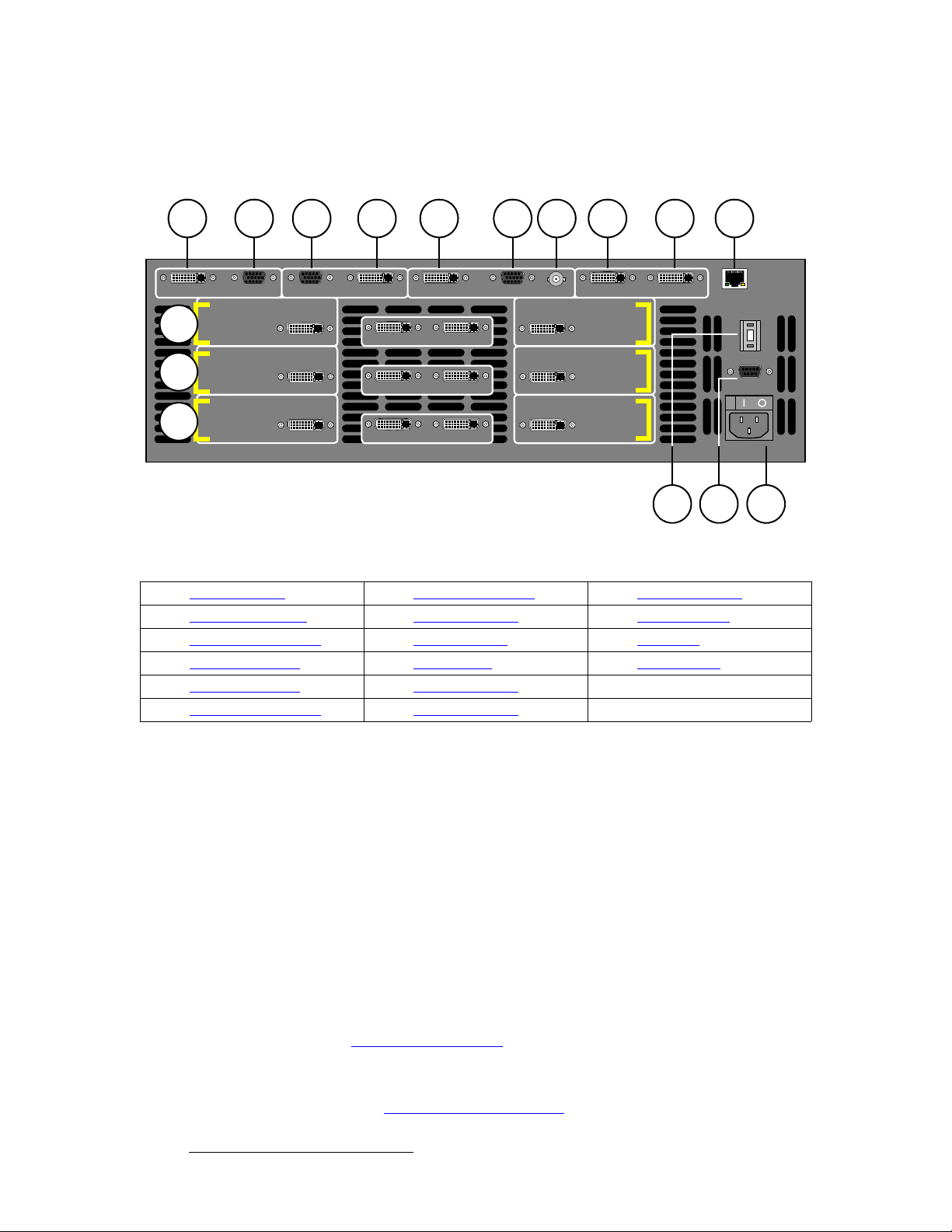
2. Hardware Orientation
Video Processors
smñ=oÉ~ê=m~åÉä
The figure below illustrates the VPx rear panel:
1
DVI PREVIEW ANALOG
11
12
13
2 3 4 5 6 7 8 9 10
Hol
es
INPUT 1A
INPUT 2A
INPUT 3A
Hol
es
ANALOG PRO GRAM 2 DVI
DVI
DVI
DVI
DVI PROGRAM 1 ANALOG
OUT INSOURCE LINK 1
OUT INSOURCE LINK 2
OUT INSOURCE LINK 3
Hol
es
HD / SDI OUT INPROGRAM LINK
DVI
DVI
DVI
INPUT 1B
INPUT 2B
INPUT 3B
ETHERNET
1514
Figure 2-4. VPx Rear Panel
1) Preview Out DVI 7) Program Out HD/SDI 13) M/E 3 Connectors
2) Preview Out Analog 8) Program Link Out 14) Unit ID Selector
3) Program 2 Out Analog 9) Program Link In 15) Serial Port
4) Program 2 Out DVI 10) Ethernet Port 16) AC Connector
5) Program 1 Out DVI 11) M/E 1 Connectors
6) Program 1 Out Analog 12) M/E 2 Connectors
1
UNIT ID
SERIAL
16
Please note:
• Connectors 1 through 10 are part of the VPx’s output board, and all output
connections are standard.
• All program and preview DVI output connectors are digital only, and do not include
analog pins.
• In a widescreen configuration, a VPx cannot function in a standalone manner, but
must always work
processor in an Encore configuration.
downstream of a standard VP. Here, a VPx cannot be the first
• In the special widescreen “preview” configuration, a VPx can be used as a
standalone destination that accepts DVI input signals only — but no other input
types are accepted, and no genlock circuitry is provided.
Following are descriptions of each rear panel connector and section on the VPx.
1) Preview Out DVI
One DVI connector is provided for Di gital Preview Output. In Appendix A, refer
DVI Connector Pinouts” section on page 369 for pinouts.
to the “
2) Preview Out Analog
One 15-pin D connector is provided for Ana lo g Preview Output. In Appendix A,
refer to the “
48 Encore Presentation System • User’s Guide • Rev 04
Analog 15-pin D Connector” section on page 371 for pinouts.
Page 49

2. Hardware Orientation
Video Processors
3) Program 2 Out Analog
One 15-pin D connector is provided for the Analog Program 2 Output. This
output is identical to the analog
edge feathering and data doubling components. In Appendix A, see the “
15-pin D Connector” section on page 371 for pinouts.
4) Program 2 Out DVI
One DVI connector is provided for the Digital Program 2 Output. This output is
identical to the digital
feathering and data doubling components. In Appendix A, refer to the “
Connector Pinouts” section on page 369 for pinouts.
5) Program 1 Out DVI
One DVI connector is provided for the Digital Program 1 Output. This output
includes all edge feathering and data doubling components, and is designed for a
digital connection to your projector. In Appendix A, refer to the “
Pinouts” section on page 369 for pinouts.
6) Program 1 Out Analog
One 15-pin D connector is provided for the Analog Program 1 Output. This
output includes all edge feathering and data doubling components, and is
designed for an analog connection to your projector. In Appendix A, see the
“
Analog 15-pin D Connector” section on page 371 for pinouts.
7) Program Out HD/SDI
One BNC connector is provided for the HD/SDI (High Definition/Serial Digital
Interface) output. Refer to the “
additional information on video outputs.
8) Program Link Out
One DVI connector is provided for the Program Link Output. To ensure proper
data doubling in wide screen configurations, this output connects to the
Link Input
on another VPx.
Program 1 Output, except that it does not include edge
Program 1 Output, except that it does not include
DVI Connector
Program Output Notes” section on page 57 for
~ In Chapter 3, refer to the “Program and Source Link Connections”
section on page 98 for details on the proper use of the connectors in
wide screen configurations.
~ In Appendix A, refer to the “DVI Connector Pinouts” section on
page 369 f or pinouts.
9) Program Link In
One DVI connector is provided for the Program Link Input. To ensure proper
data doubling in wide screen configurations, this input connects to the
Link Output
from another VP (or VPx).
Program
~ In Chapter 3, refer to the “Program and Source Link Connections”
section on page 98 for details on wide screen configurations.
~ In Appendix A, refer to the “DVI Connector Pinouts” section on
page 369 f or pinouts.
Analog
DVI
Program
Encore Presentation System • User’s Guide • Rev 04 49
Page 50

2. Hardware Orientation
Video Processors
10) Ethernet Port
One RJ-45 connector is provided for 10/100BaseT Ethernet communications.
For multiple connections, use an Ethernet switch on an isolated network.
11) M/E 1 Connectors 12) M/E 2 Connectors 13) M/E 3 Connectors
Six analog and digital connectors are provided for each M/E. Please note:
~ All M/E boards are identical on a VPx. See the “M/E Connectors (VPx)” ~ Refer to the “A Word About M/E Connector Priority” section on
14) Unit ID Selector
One 16-position selector (with physical digits 0 - 15) is provided for setting an
unique
section on page 52 for details.
page 50 for information on M/E connector priority.
ID on a VPx The selector enables you to assign logical IDs 1 to 16.
Note
By default, a VPx is configured as an
an IP address when it sees a
configured (by default) as DHCP Servers.
Note
Note
15) Serial Port
One 9-pin D connector is provided for RS-232 serial communications with the
VPx. In Appendix A, see the “
16) AC Connector
One AC Connector is provided to connect the VPx to your AC source.
See the “
Program Output Notes” section on page 57 for more information on VPx outputs.
Physical digit 0 equates to logical ID 16.
DHCP Client, and it automatically obtains
DHCP Server. Controller Models SC and LC are
Always ensure that each VPx has a unique ID. During setup,
the
ID is used during various configuration procedures.
Using the Miscellaneous Menu, you can re-define IDs using
numbers
Menu” section on page 196 for details.
17 - 32. In Chapter 5, refer to the “Miscellaneous
Serial Connector” section on page 373 for pinouts.
^=tзкЗ=^Дзмн=jLb=`зееЙЕнзк=mкбзкбну
Depending on your VP or VPx configuration, the M/E connectors on the rear of the chassis
do not necessarily relate 1:1 to the layer buttons in the Controller’s
Please note:
Layer Control Section.
• The Controller’s layer buttons are arranged left-to-right in order of visual priority,
from the lowest (
Mixer 1) to the highest (Mixer 3 ).
• The M/E boards are arranged in order of electronic priority, from the lowest (M/E
3) to the highest (M/E 1).
• Electronic priority does not equate 1:1 to visual priority, with regard to the silk-
screened labels on the Controller.
50 Encore Presentation System • User’s Guide • Rev 04
Page 51

2. Hardware Orientation
Video Processors
With this in mind, the information below lists how the physical connectors relate to the
various mixers on different VP and VPx configurations. Keep this correlation in mind when
you are making rear-panel connections.
• In a 3 M/E system:
~ M/E 1 connectors are the highest priority. They appear as Mixer 3 on
the Controller. The DSK will be connected to the M/E 1 board.
~ M/E 2 connectors have middle priority. They appear as Mixer 2.
~ M/E 3 connectors are the lowest priority. They appear as Mixer 1.
Background sources will be connected to the M/E 3 board.
• In a 2 M/E system:
~ M/E 1 connectors are the highest priority, and appear as Mixer 2. The
DSK will be connected to the M/E 1 board.
~ M/E 2 connectors are the lowest priority, and appear as Mixer 1.
Background sources will be connected to the M/E 2 board.
~ M/E 3 connectors are not installed.
• In a 1 M/E system:
~ M/E 1 connector priorities are relative to the connectors being used:
•The
•The
This leaves the other connectors to fall in between Background and
DSK. The rule stating that “
connectors still holds.
DVI Input A or Analog Input A connector could be set up
as a Background input (lowest priority).
DVI Input B or Analog Input B connector could be setup
as a DSK input (highest priority).
A” connectors are lower in priority than “B”
~ M/E 2 and 3 connectors are not installed.
Encore Presentation System • User’s Guide • Rev 04 51
Page 52

2. Hardware Orientation
Video Processors
jLb=`зееЙЕнзкл=EsmF
The figure below illustrates a close-up of the M/E connectors on the VP. Even though the
figure uses M/E 1’s board, all M/E connections are identical.
a b c d e f g h
HD / SDI
Hol
es
ANALOG
a) Analog Input A d) Source Link Out g) HD/SDI Input B
b) HD/SDI Input A e) Source Link In h) Analog Input B
c) DVI Input A f) DVI Input B
INPUT 1A
DVI
Figure 2-5. M/E Connectors, VP
OUT INSOURCE LINK 1
DVI
HD / SDI
INPUT 1B
On each M/E, three input connections are provided for layer A, three are provided for layer
B, and two “Link” connectors are provided for inter-Processor communications.
Following are descriptions of each M/E connector.
a) Analog Input A
One 15-pin D connector is provided for the input to the M/E’s Layer A — visually ,
the lower priority of the two layers. Connect a VGA source directly, or connect the
output of a VGA router. This input can also be used for composite and component
video. See the “
In Appendix A, see the “
M/E Input Notes” section on page 56 for additional information.
Analog 15-pin D Connector” section on page 371 for
pinout details.
b) HD/SDI Input A
One BNC connector is provided for the HD/SDI input to Layer A. Connect an SDI
or HDTV source directly, or connect the output of an SDI or HDTV router . Refer to
the “
M/E Input Notes” section on page 56 for more information.
c) DVI Input A
One DVI-I connector is provided for both digital and analog inputs to the M/E’s
Layer A and background channel.
~ Digital — connect a digital graphics source directly, or connect the
output of a digital graphics router.
~ Analog — using the appropriate adapter cable, connect an analog VGA
source directly, or connect the output of a VGA router.
Refer to the “
of this connector’s analog component. In Appendix A, refer to the “
Connector Pinouts” section on page 370 for pinout details.
d) Source Link Out
One DVI connector is provided for the M/E’s Source Link Output. For wide
screen and multi-screen applications, this connector loops your inputs to the
VP or VPx in the chain. Because all analog and digital inputs reside in the digital
domain inside the VP, each “link” output loops inputs to the next VP’s scalers.
M/E Input Notes” section on page 56 for important details on the use
Hol
es
ANALOG
DVI-I
next
52 Encore Presentation System • User’s Guide • Rev 04
Page 53

2. Hardware Orientation
Video Processors
An M/E’s Source Link Output must always be connected to its associated M/E
Source Link Input on the next chassis, and never cross-routed.
S Connect M/E 2’s Source Link Output on Processor 1 to M/E 2’s
Source Link Input on Processor 2.
Please note:
~ In a multi-chassis configuration, the link can extend to all chassis.
~ In all cases, the looped inputs are “pre-scaler.”
In Chapter 3, refer to the “
page 98 for details on proper conne ctor usage in wide screen configurations.
In Appendix A, refer to the “
pinout details.
e) Source Link In
One DVI connector is provided for the M/E’s Source Link Input. For wide screen
and multi-screen applications, this connector accepts the looped outputs from the
previous VP or VPx in the chain. An M/E’s
connected to its associated M/E
and never cross-routed.
In Chapter 3, refer to the “
page 98 for details on proper conne ctor usage in wide screen configurations.
In Appendix A, refer to the “
pinout details.
f) DVI Input B
One DVI-I connector is provided for both digital and analog inputs to the M/E’s
Layer B and background channel.
Program and Source Link Connections” section on
DVI Connector Pinouts” section on page369 for
Source Link Input must always be
Source Link Output on the previous chassis,
Program and Source Link Connections” section on
DVI Connector Pinouts” section on page369 for
~ Digital — connect a digital graphics source directly to this input, or more
typically, connect the output of a digital graphics router.
~ Analog — using the appropriate adapter, connect an analog VGA
source or the output of a VGA router directly to this input.
Refer to the “
connector’s analog component. In Appendix A, refer to th e “
Pinouts” section on page 370 for pinout details.
g) HD/SDI Input B
One BNC connector is provided for the HD/SDI input to Layer B. Connect an SDI
or HDTV source directly, or connect the output of an SDI or HDTV router . Refer to
the “
M/E Input Notes” section on page 56 for additional information.
h) Analog Input B
One 15-pin D connector is provided for the input to the M/E’s Layer B — visually,
the higher priority of the two by default. Connect a VGA source or the output of a
VGA router. This input can also be used for composite and component video.
See the “
In Appendix A, see the “
pinout details.
M/E Input Notes” section on page 56 for details on the use of this
DVI-I Connector
M/E Input Notes” section on page 56 for information about video inputs.
Analog 15-pin D Connector” section on page 371 for
Encore Presentation System • User’s Guide • Rev 04 53
Page 54

2. Hardware Orientation
Video Processors
jLb=`зееЙЕнзкл=EsmсF
The figure below illustrates a close-up of the M/E connectors on the VPx. Even though the
figure uses M/E 1’s board, all M/E connections are identical on the VPx.
Note
The M/E connectors on a VPx are identical to those on a VP,
minus the analog and HD/SDI connectors.
a b c d
INPUT 1A
a) DVI Input A c) Source Link In d) DVI Input B
b) Source Link Out
DVI
Figure 2-6. M/E Connectors, VPx
OUT INSOURCE LINK 1
DVI
On each M/E, one input connection is provided for layer A, one for layer B, and two “Link”
connectors for inter-Processor communications.
Important
In a widescreen configuration, a VPx cannot function in a
standalone manner, but must always work
standard VP. Here, a VPx cannot be the first processor in an
Encore configuration.
In the special widescreen “preview” configuration, a VPx
be used as a standalone destination that accepts DVI input
signals only — but no other input types are accepted, and no
genlock circuitry is provided.
INPUT 1B
downstream of a
can
Following are descriptions of each M/E connector on a VPx.
a) DVI Input A
One DVI-I connector is provided for both digital and analog inputs to the M/E’s
Layer A and background channel.
~ Digital — connect a digital graphics source directly, or connect the
output of a digital graphics router.
~ Analog — using the appropriate adapter cable, connect an analog VGA
source directly, or connect the output of a VGA router.
Refer to the “
of this connector’s analog component. In Appendix A, refer to the “
Connector Pinouts” section on page 370 for pinout details.
54 Encore Presentation System • User’s Guide • Rev 04
M/E Input Notes” section on page 56 for important details on the use
DVI-I
Page 55

2. Hardware Orientation
Video Processors
b) Source Link Out
One DVI connector is provided for the M/E’s Source Link Output. For wide
screen and multi-screen applications, this connector loops your inputs to the
VP or VPx in the chain. Because all analog and digital inputs reside in the digital
domain, each “link” output loops those inputs to the next Processor’s scalers.
An M/E’s
Source Link Input on the next chassis, and never cross-routed.
Please note:
Source Link Output must always be connected to its associated M/E
~ In a multi-chassis configuration, the link can extend to all chassis.
~ In all cases, the looped inputs are “pre-scaler.”
In Chapter 3, refer to the “
page 98 for details on proper conne ctor usage in wide screen configurations.
In Appendix A, refer to the “
pinout details.
c) Source Link In
One DVI connector is provided for the M/E’s Source Link Input. For wide screen
and multi-screen applications, this connector accepts the looped outputs from the
previous VP or VPx in the chain. An M/E’s
connected to its associated M/E
and never cross-routed.
In Chapter 3, refer to the “
page 98 for details on proper conne ctor usage in wide screen configurations.
In Appendix A, refer to the “
pinout details.
d) DVI Input B
One DVI-I connector is provided for both digital and analog inputs to the M/E’s
Layer B and background channel.
Program and Source Link Connections” section on
DVI Connector Pinouts” section on page369 for
Source Link Input must always be
Source Link Output on the previous chassis,
Program and Source Link Connections” section on
DVI Connector Pinouts” section on page369 for
~ Digital — connect a digital graphics source directly to this input, or more
typically, connect the output of a digital graphics router.
~ Analog — using the appropriate adapter cable, connect an analog VGA
source directly to this input, or more typically, connect the output of a
VGA router.
Refer to the “
connector’s analog component. In Appendix A, refer to th e “
Pinouts” section on page 370 for pinout details.
M/E Input Notes” section on page 56 for details on the use of this
DVI-I Connector
next
Encore Presentation System • User’s Guide • Rev 04 55
Page 56

2. Hardware Orientation
M/E Input Notes
jLb=fåéìí=kçíÉë
Please note the following important points regarding M/E inputs:
• Single Processor Configurations (VP and VPx) — Inputs are connected to the
VP in the normal manner. You can connect a total of six inputs to each M/E:
~ Three inputs can connect to layer A (HD/SDI, analog and DVI).
~ Three inputs can connect to layer B (HD/SDI, analog and DVI).
Note
Using the setup menus, each input can be assigned to a source button on the
Controller, but only two inputs can be used “on air” from an M/E at a time — the
one assigned to layer A and the one assigned to layer B.
Thus, in a three-M/E configuration, you can populate all 18 physical inputs, but
only six PIPs can be used “on air” — using both layers on each mixer.
In a widescreen configuration, a VPx cannot function in a
standalone manner, but must always work
standard VP. Here, a VPx cannot be the first processor in an
Encore configuration.
In the special widescreen “preview” configuration, a VPx
be used as a standalone destination that accepts DVI input
signals only — but no other input types are accepted, and no
genlock circuitry is provided.
downstream of a
can
• Multiple Processor Configurations (VP and VPx) — In these configurations,
you only need to connect inputs to the first Processor. Inputs are automatically
looped to all other Processors via the
Source Link connections.
• Routers (VP only) — You can connect sources directly to the M/E inputs, or for
the greatest flexibility, you to connect router outputs to the M/E inputs. In this
manner, one input represents any number of video or graphic sources.
• HD/SDI Inputs (VP Only) — For the two HD/SDI input connectors on an M/E, you
can set the input to accept
(SMPTE 292M, HDTV).
SDI (SMPTE 259M-C, NTSC or PAL) or HD-SDI
• DVI-I Connectors (VP and VPx) — There are two DVI-I input connectors for each
M/E (
A and B), and each contains both a digital and an analog input. Depending
upon your application (and the location of the M/E), you can use the input for a
scaled or an unscaled source:
~ The “digital” side accepts connections from a standard DVI output or
digital graphic router. This side of the input can be used as both a scaled
input source or as an unscaled
Background / DSK source.
~ Using a breakout cable, the “analog” side accepts connections from a
VGA output or VGA router. This side is designed for inputting the
system’s unscaled sources —
• The lowest priority M/E in your system must be used for
inputting the
• The highest priority M/E in your system must be used for
inputting the
Background source.
DSK source.
Background and DSK.
56 Encore Presentation System • User’s Guide • Rev 04
Page 57

mкзЦк~г=lмнймн=kзнЙл
For both VP and VPx units, please note the following important points regarding the
Processor’s program outputs:
• HD/SDI Outputs — For the HD/SDI output, you can set the output to be SDI
(SMPTE 259M-C, NTSC or PAL) or
set this output resolutions, all output connectors will output that same resolution.
• DVI Program Outputs — DVI Program outputs are digital only . They do not have
analog connections.
• Program 1 Outputs — Edge feathering and data doubling are present on all
Program 1 Outputs, provided that those features are enabled in the system’s
Output Menu.
^е~дзЦ=fеймн=cдЙсбДбдбну
For VPs only, each M/E’s Analog Input connectors (A and B) accept a variety of analog
formats including VGA, low-resolution composite, S-video and YUV component video.
• For RGB with H and V sync, use the VGA connector directly.
• Using a (customer supplied) VGA to 5xBNC breakout cable, five input
combinations are possible. Cells with check marks denote the connections
required for the indicated format.
2. Hardware Orientation
Program Output Notes
HD-SDI (SMPTE 292M, HDTV). When you
Table 2-1. Analog Input Combinations using Breakout Cable
Breakout Cable
Wire Color
R
G
B 3 (Pb)
H Sync
V Sync
Composite
Video
S-Video
(Y/C)
3 (Chrom)
33 (Lum)
YUV
(YP
3 (P
3 (Lum)
)
bPr
) 3
r
RGB
Sync on Green
RGB
Comp Sync
RGB
Separate H V
33
333
333
33
3
Encore Presentation System • User’s Guide • Rev 04 57
Page 58

2. Hardware Orientation
Controller Rear Panels
`зенкзддЙк=oЙ~к=m~еЙдл
The figure below illustrates the rear panel connectors on both Controllers (SC and LC).
The panels are identical on both models.
4 8
ETHERNET
100-240 V
47-63Hz, 2.75A
KEYBOARD USB B
MultiMedia Card
1
1) Keyboard Port 4) Ethernet Port 7) Tally Connector
2) USB B Port 5) Ext Comm 8) AC Power
3) MultiMedia Card Slot 6) Console Port
2
Figure 2-7. Controller Rear Panel Connectors
3 5 6 7
EXT COMM
CONSOLE TALLY
Following are descriptions of each rear panel connector:
1) Keyboard Port
One standard PS/2 connector is provided for the Keyboard Port. When a
customer-supplied PS/2 style keyboard is connected, certain numeric entry and
“naming” functions can be performed. In Chapter 7, refer to the “
Using the PS/2
Keyboard” section on page 31 1 for details.
2) USB B Port
Note
This connector is not implemented.
58 Encore Presentation System • User’s Guide • Rev 04
Page 59

2. Hardware Orientation
Controller Rear Panels
3) MultiMedia Card Slot
One MultiMedia Card Slot is provided for a Flash Memory Card connection to the
Controller. The flash card enables you to store and recall system configurations,
and transfer them between Controllers as required. In Chapter 5, refer to the
“
Miscellaneous Menu” section on page 196 for details on backup and restore.
4) Ethernet Port
One RJ-45 connector is provided for 10/100BaseT Ethernet communications with
the Encore Processor. The Ethernet connector is compatible with:
~ Standard RJ-45 Ethernet cables
~ Neutrik EtherCon
For multiple connections in an Encore system, an Ethernet switch on an isolated
network is recommended. In Appendix A, refer to the “
section on page 372 for pinout details.
5) Ext Comm
One 9-pin D connector is provided for RS-232 serial communications with a serial
device, such as a router. In Appendix A, refer to the “
on page 373 for pinout details.
6) Console Port
One 9-pin D connector is provided for RS-232 serial communications with an
ASCII terminal for command-line control of the Encore system. In Appendix A,
refer to the “
7) Tally Connector
One 25-pin D connector is provided for issuing tally “relay closure” commands to
external devices such as cameras. Eight tally circuits are provided. In
Appendix A, refer to the “
8) AC Power
Use the AC Power connector to connect the Controller to your facility’s AC power
source. The integral switch turns the Controller on and off.
Serial Connector” section on page 373 for pinout details.
®
series cables
Ethernet Connector”
Serial Connector” section
Tally Connector” section on page 374 for pinout details.
Encore Presentation System • User’s Guide • Rev 04 59
Page 60

2. Hardware Orientation
Controller Rear Panels
60 Encore Presentation System • User’s Guide • Rev 04
Page 61

PK==e~êÇï~êÉ=fåëí~ää~íáçå
få=qÜáë=`Ü~éíÉê
This chapter provides comprehensive installation instructions for the Encore system’s
hardware. The following topics are discussed:
• Safety Precautions
• Unpacking and Inspection
• Site Preparation
• Rack-Mount Installation
• Cable and Adapter Information
• Installation
• Connection Charts
• Program and Source Link Connections
Note
Once you have reviewed all of the sections in this chapter,
please continue with Chapter 4, “
page 107.
Controller Orientation” on
Encore Presentation System • User’s Guide • Rev 04 61
Page 62

3. Hardware Installation
Safety Precautions
p~СЙну=mкЙЕ~мнбзел=
For all Encore Presentation System installation procedures, observe the following
important safety and handling rules to avoid damage to yourself and the equipment:
• To protect users from electric shock, ensure that the power supplies for each VP,
VPx and Control Panel connect to earth via the ground wire provided in the AC
power Cord.
• The AC Socket-outlet should be installed near the equipment and be easily
accessible.
rей~ЕвбеЦ=~еЗ=fелйЙЕнбзе=
Before opening the boxes, inspect them for damage. If you find any damage, notify the
shipping carrier immediately for all claims adjustments. As you open each box, compare its
contents against the packing slips. If you find any shortages, contact your Barco sales
representative.
Once you have removed all the components from their packaging and checked that all the
listed components are present, visually inspect each Controller and Processor to ensure
there was no damage during shipping. If there is damage, notify the shipping carrier
immediately for all claims adjustments.
páíÉ=mêÉé~ê~íáçå=
The environment in which you install your Encore Presentation System should be clean,
properly lit, free from static, and have adequate power, ventilation, and space for all
components.
o~ÅâJjçìåí=fåëí~ää~íáçå
Encore VP and VPx units are designed to be rack mounted, and are supplied with front
rack-mount hardware. Rear rack-mount brackets are available as a kit, and are
recommended when units are mounted in transit cases.
When rack mounting VP and VPx units, remember the following important points:
• Maximum ambient operating temperature for the unit is 40 degrees C.
• Leave at least one inch of space (front and rear) to ensure that the airflow through
the fan and vent holes is not restricted.
• Distribute the units evenly to prevent hazardous conditions that may be created by
uneven weight distribution.
• Rack mount the units from the front rack ears using four rack screws (not
supplied). Threads may be metric or otherwise — depending upon the rack type.
• Install the lower of the two mounting holes first.
62 Encore Presentation System • User’s Guide • Rev 04
Page 63

`~ДдЙ=~еЗ=^З~йнЙк=fеСзкг~нбзе
The table below provides cable and adapter information:
Table 3-1. Encore Presentation System Cables and Adapters
Cable Description
DVI-to-VGA Analog Adapters Included *
DVI Program and Source Link Cables Included, DVI-M to DVI-M, 1 Meter length *
Analog Input Cables Customer Supplied
DVI Input Cables Customer Supplied
Analog Breakout Cables Customer Supplied
RJ-45 Ethernet Cable Customer Supplied
Ethernet Switch Customer Supplied
3. Hardware Installation
Cable and Adapter Information
Additional DVI-to-VGA Adapters Optional
DVI Extension Cables Optional, 1.5 ft. length
DVI to 5xBNC Breakout Cable Optional
* Cable and adapter quantities depend on the number of M/Es
purchased in each VP or VPx.
Encore Presentation System • User’s Guide • Rev 04 63
Page 64

3. Hardware Installation
Installation
fåëí~ää~íáçå
Detailed installation procedures are provided for the Encore configurations listed below.
Select the desired configuration, and follow all procedures as listed:
• Single Screen Configuration
• Triple Screen Configuration
• Wide Screen Configuration
• Wide Screen Configuration Plus Wide Screen Preview
• Single Screen Stack Configuration
• Wide Screen Stack Configuration
64 Encore Presentation System • User’s Guide • Rev 04
Page 65

3. Hardware Installation
Installation
pбеЦдЙ=pЕкЙЙе=`зеСбЦмк~нбзе
The figure below illustrates a block diagram of a single screen Encore configu ration. Use
this diagram for reference in the following procedure. Please note:
• Aux destinations are not shown in the diagram below.
ProjectorProgram Preview
M/E Inputs
Scaled
Sources
Unscaled
Sources
ScreenPRO-II
PresentationPRO-II
ImagePRO
Encore Video Processor
To:
Routers
Ethernet Switch
PG 2
PVW
PG 1
Controller SC or LC
Figure 3-1. Block Diagram, Single Screen Encore Configuration
For this configuration, you will need:
Table 3-2. Equipment List, Single Screen Encore Configuration
Qty. Item Note
1 VP VPx cannot be used
1 Controller Model LC or SC
1 Video Projector Customer supplied
2 DVI or Analog Monitors Program and Preview (customer supplied)
1 Ethernet Switch Customer supplied
2 Ethernet cables Customer supplied. Additional cables required for routers.
TBD Sources, routers, cables Analog, Video and/or DVI as required (customer supplied)
Use the following steps to install a single screen Encore configuration:
1. Follow the unpacking proced ure s as l isted in the “Unpacking and Inspection”
section on page 62.
Encore Presentation System • User’s Guide • Rev 04 65
Page 66

3. Hardware Installation
Installation
2. In Appendix A, refer to the “Physical and Electrical Specifications” section on
page 367 for electrical and mechanical details.
3. In Chapter 2, refer to the “Video Processor Rear Panel” section on page 45 and
the “
Controller Rear Panels” section on page 58 for all connector locations.
4. For the VP, follow the rack mount procedures as outlined in the “Rack-Mount
Installation” section on page 62.
Note
5. Ethernet Connections — a totally “local” network connection is recommended.
Using Ethernet cables:
a. Connect the VP and Controller to the Ethernet Switch, then connect
router(s) to the Switch.
b. As required, connect ScreenPRO-II, PresentationPRO-II and ImagePRO
systems to the Switch.
6. Direct Source Connections — if you elect to use direct connections in place of
(or in addition to) router connections:
a. As an important prerequisite, complete your “Connection Charts” on
page 89 to streamli ne your source installation procedure.
b. Using the information from the chart, connect the desired “direct”
sources to each M/E’s input connectors as required.
c. As required, connect unscaled background and DSK sources, as
provided from a PC’s single head graphics card.
7. D/A Connections —
a. If your system includes analog, SDI or DVI D/As, connect video inputs to
the D/As as required.
b. Connect D/A outputs to the to the desired M/E input connectors.
8. Router Connections — if you elect to use router connections in place of (or in
addition to) direct connections:
a. For Ethernet controlled routers, ensure that the router(s) are connected
to the same Ethernet Switch as the Controller and Processor. Ensure
that each router has a unique IP address.
b. To connect a single serial controlled router, use an RS-232 cable to
connect the router to the Controller’s
refer to the “
c. To connect two (or more) serial routers, a third-party Ethernet-to-Serial
converter is required, such as the
UDS2100 (http://www.lantronix.com). Each UDS2100 can control two
serial routers.
A VPx can only be used in a single processor configuration in
the special widescreen “preview” mode. Refer to the “
Screen Configuration Plus Wide Screen Preview” section
on page 76 for details.
EXT COMM port. In Chapter 2,
Controller Rear Panels” section on page 58 for details.
Lantronix model UDS100, UDS200 or
• Using RS-232 cables, connect each router to the
• Set up a static IP address on the Lantronix. The recommended
range is
with Encore devices. See the
• Using an Ethernet cable, connect the
Ethernet Switch as the Controller and Processor(s).
192.168.0.191 - 192.168.0.240 — so as not to conflict
Lantronix User’s Guide.
UDS2100 to the same
Wide
UDS2100.
66 Encore Presentation System • User’s Guide • Rev 04
Page 67

3. Hardware Installation
Installation
d. Ensure that all sources are properly connected to your router(s).
e. Connect all selected router outputs to the desired M/E inputs.
9. ScreenPRO-II Connections — if your system includes one (or more) destination
ScreenPRO-II units, you can configure the unit for internal or external routing:
a. When External routers are used, connect two outputs from an Analog
router to
can also be connected to BNC inputs
specific patches will be defined using the
b. When Internal routing is used, connect Analog sources to inputs 1 - 8 on
the HD-15 connectors, and SDI sources to BNC inputs
setup, these patches will be defined using the
In Chapter 6, refer to the “
for more information.
10. Output Connections —
a. Connect the VP’s analog or digital Preview Output to the input of your
Preview Monitor.
b. Connect the VP’s analog or digital Program 2 Output to the input of your
Program Monitor.
c. Connect the analog or digital Program 1 Output to the projector input.
d. Connect the Program Out HD/SDI connector to an SDI or HDTV
monitor, or to the proper video distribution equipment.
any two HD-15 inputs on the ScreenPRO-II. An SDI router
1 and 2. During setup, these
Output Patch Menu.
1 and 2. During
Input Patch Menu.
ScreenPRO-II Destination Setup” section on page 279
Note
11. Aux Destinations — you can configure three types of Aux destinations: Aux
(monitors),
Working With Destinations” on page 393 for interconnection details.
“
12. Power Connection — connect AC power cords to the AC Power Connectors on
the rear of the VP and Controller, and then to AC outlets. Connect AC Power
cords (or AC adapters) to all peripheral equipment. Please note:
ImagePRO Aux and PresentationPRO-II Aux. Refer to Appendix D,
This output only works if the selected output resolution is a
valid SDI or HD/SDI format.
~ Connect each unit only to a properly rated supply circuit.
~ Reliable grounding of rack-mounted equipment should be maintained.
13. Tally Connection — the Controller provides one 25-pin D connector for issuing
“relay closure” commands to external devices. Eight circuits are provided. In
Appendix A, refer to the “
14. System ID — Using the Unit ID Selector, set the ID of the VP to 1.
Note
15. If your system includes remote destinations such as ScreenPRO-II units, refer to
Appendix D, “
16. Power On — all power on instructions are covered in Chapter 6.
Please continue with Chapter 4, “
Working With Destinations” on page 393 for connection details.
Tally Connector” section on page 374 for details.
Using the Miscellaneous Menu, you can redefine IDs using
numbers
Menu” section on page 196 for details.
17 - 32. In Chapter 5, refer to the “Miscellaneous
Controller Orientation” on page 107.
Encore Presentation System • User’s Guide • Rev 04 67
Page 68

3. Hardware Installation
Installation
qкбйдЙ=pЕкЙЙе=`зеСбЦмк~нбзе
The figure below illustrates a block diagram of a triple screen Encore configuration. This
diagram can be used as reference in the procedure. Please note:
• Aux destinations are not shown in the diagram below.
• This procedure can be used for configurations consisting of from 2 to 32 screens.
• A VP must be used for each single destination. VPx cannot be used.
M/E Inputs
Scaled
Sources
Unscaled
Sources
Scaled
Sources
Unscaled
Sources
Scaled
Sources
Unscaled
Sources
Program #1 Program #2 Program #3
Preview #1 Preview #2 Preview #3
VP #1
PG 2
PVW
PG 1
VP #2
PG 2
PVW
PG 1
VP #3
PG 2
PVW
PG 1
To:
Routers
ScreenPRO-II
PresentationPRO-II
ImagePRO
Ethernet Switch
Projector #1 Projector #2 Projector #3
Controller SC or LC
Figure 3-2. Block Diagram, Triple Screen Encore Configuration
For this configuration, you will need:
Table 3-3. Equipment List, Triple Screen Encore Configuration
Qty. Item Note
3 VP VPx cannot be used.
1 Controller Model LC or SC
3 Video Projectors Customer supplied.
6 DVI or Analog Monitors Program and Preview (customer supplied).
1 Ethernet Switch Customer supplied
68 Encore Presentation System • User’s Guide • Rev 04
Page 69

3. Hardware Installation
Table 3-3. Equipment List, Triple Screen Encore Configuration (Continued)
Qty. Item Note
4 Ethernet cables Customer supplied. Additional cables required for routers.
TBD Sources, routers, cables Analog, Video and/or DVI as required (customer supplied)
Use the following steps to install a triple screen Encore configuration:
1. Follow the unpacking proced ure s as l isted in the “Unpacking and Inspection”
section on page 62.
2. In Appendix A, refer to the “Physical and Electrical Specifications” section on
page 367 for electrical and mechanical details.
3. In Chapter 2, refer to the “Video Processor Rear Panel” section on page 45 and
the “
Controller Rear Panels” section on page 58 for all connector locations.
4. For each VP, follow the rack mount procedures as outlined in the “Rack-Mount
Installation” section on page 62.
Installation
Note
5. Ethernet Connections — a totally “local” network connection is recommended:
a. Connect the VPs and Controller to the Ethernet Switch.
b. Connect router(s) to the Switch.
c. As required, connect ScreenPRO-II, PresentationPRO-II and ImagePRO
systems to the Switch.
6. Direct Source Connections — if you elect to use direct connections, in place of
(or in addition to) router connections:
a. As an important prerequisite, complete your “Connection Charts” on
page 89 to streamli ne your source installation procedure.
b. Using information from the chart, connect the desired “direct” sources to
each M/E’s input connectors as required — on each Processor.
c. As required, connect unscaled background and DSK sources, as
provided from a PC’s single head graphics card.
7. D/A Connections —
a.
If your system includes analog, SDI or DVI D/As, connect video inputs to
the D/As as required.
b. Connect D/A outputs to the to the desired M/E input connectors.
8. Router Connections — if you elect to use router connections, in place of (or in
addition to) direct connections:
a. For Ethernet controlled routers:
b. To connect a single serial controlled router, use an RS-232 cable to
connect the router to the Controller’s
refer to the “
A VPx cannot be used in a single processor configuration.
• Ensure that the router(s) are connected to the same Ethernet
Switch as the Controller and VPs.
• Ensure that each router has an unique IP address.
EXT COMM port. In Chapter 2,
Controller Rear Panels” section on page 58 for details.
Encore Presentation System • User’s Guide • Rev 04 69
Page 70

3. Hardware Installation
Installation
c. To connect two (or more) serial routers, a third-party Ethernet-to-Serial
d. Ensure that all sources are connected to your ro uter(s).
e. Connect all selected router outputs to the desired M/E inputs.
9. ScreenPRO-II Connections — if your system includes one (or more) destination
ScreenPRO-II units, you can configure them for internal or external routing:
a. When External routers are used, connect two outputs from an Analog
b. When Internal routing is used, connect Analog sources to inputs 1 - 8 on
In Chapter 6, refer to the “
for more information.
10. Output Connections —
a. For each VP, connect the analog or digital Preview Output to the input
b. For each VP, connect the analog or digital Program 2 Output to the
c. For each VP, connect the analog or digital Program 1 Output to the
d. Connect the Program Out HD/SDI connector to an SDI or HDTV monitor
converter is required, such as the
UDS2100 (http://www.lantronix.com). Each UDS2100 can control two
serial routers.
• Using RS-232 cables, connect each router to the
• Set up a static IP address on the Lantronix. The recommended
range is
with Encore devices. See the
• Using an Ethernet cable, connect the
switch as the Controller and VPs.
router to
can also be connected to BNC inputs
specific patches will be defined using the
the HD-15 connectors, and SDI sources to BNC inputs
setup, these patches will be defined using the
of the associated Preview Monitor.
input of the associated Program Monitor.
input of the associated projector.
as required, or to the proper video distribution equipment.
any two HD-15 inputs on the ScreenPRO-II. An SDI router
192.168.0.191 - 192.168.0.240 — so as not to conflict
ScreenPRO-II Destination Setup” section on page 279
Lantronix model UDS100, UDS200 or
UDS2100.
Lantronix User’s Guide.
UDS2100 to the same
1 and 2. During setup, these
Output Patch Menu.
1 and 2. During
Input Patch Menu.
Note
11. Aux Destinations — you can configure three types of Aux destinations: Aux
(monitors),
Working With Destinations” on page 393 for interconnection details.
“
12. Power Connection — connect AC power cords to the AC Power Connectors on
the rear of each VP and Controller, and then to AC outlets. Connect AC Power
cords (or AC adapters) to all peripheral equipment. Please note:
ImagePRO Aux and PresentationPRO-II Aux. Refer to Appendix D,
This output only works if the selected output resolution is a
valid SDI or HD/SDI format.
~ Connect each unit only to a properly rated supply circuit.
~ Reliable grounding of rack-mounted equipment should be maintained.
13. Tally Connection — the Controller provides one 25-pin D connector for issuing
tally “relay closure” commands to external devices. Eight circuits are provided. In
Appendix A, refer to the “
70 Encore Presentation System • User’s Guide • Rev 04
Tally Connector” section on page 374 for details.
Page 71

3. Hardware Installation
Installation
14. System ID — Using the Unit ID Selector, set the ID of VP #1 to 1, VP #2 to 2, VP
#3 to
3. Each Processor must have a unique ID.
Note
15. Power On — all power on instructions are covered in Chapter 6.
With all connections made, continue with Chapter 4, “
page 107.
Using the Miscellaneous Menu, you can redefine IDs using
numbers
Menu” section on page 196 for details.
17 - 32. In Chapter 5, refer to the “Miscellaneous
Controller Orientation” on
Encore Presentation System • User’s Guide • Rev 04 71
Page 72

3. Hardware Installation
Installation
tбЗЙ=pЕкЙЙе=`зеСбЦмк~нбзе
The figure below illustrates a block diagram of a “triple” wide screen configuration. Use this
diagram for reference in the following procedure. Please note:
• Aux destinations are not shown in the diagram below.
• This procedure can be used for wide screen configurations consisting of from 2 to
32 screens. Horizontal, vertical, and “array” blending is set using the
Setup Menu.
• A VP must be used as the “master” processor. Thereafter, either a VP or a VPx
can be used.
Destination
M/E Inputs
Scaled
Sources
Unscaled
Sources
Unscaled
Sources
Unscaled
Sources
Program #1 Program #2 Program #3
Preview #1 Preview #2 Preview #3
Note: #1 is VP only, not VPx
VP #1
PG 2
PVW
PG 1
VP or VPx #2
VP or VPx #3
Program
Program
Link
Link
Source
Link
Source
Link
PG 2
PVW
PG 1
PG 2
PVW
PG 1
Projector #1 Projector #2 Projector #3
To:
Routers
ScreenPRO-II
PresentationPRO-II
ImagePRO
Ethernet Switch
Controller SC or LC
Figure 3-3. Block Diagram, Wide Screen Encore Configuration
For this procedure, you will need:
Table 3-4. Equipment List, Wide Screen Encore Configuration
Qty. Item Note
1 VP VPx cannot be used as the “master” processor
2 VP or VPx Use either processor as a “slave” unit in a widescreen configuration
72 Encore Presentation System • User’s Guide • Rev 04
Page 73

3. Hardware Installation
Table 3-4. Equipment List, Wide Screen Encore Configuration (Continued)
Qty. Item Note
1 Controller Model LC or SC
3 Video Projectors Customer supplied.
6 DVI or Analog Monitors Program and Preview (customer supplied).
1 Ethernet Switch Customer supplied
4 Ethernet cables Customer supplied. Additional cables required for routers.
Installation
TBD Program Link Cables (DVI-I) Use 1 for double wide screen application,
Use 2 for triple wide screen application, left justification
Use 2 for double wide screen application, center justification
Use 3 for triple wide screen application, center justification
TDB Source Link Cables (DVI-I) Dependent on the number of M/Es installed in the Processors
TBD Sources, routers and cables Analog, Video and/or DVI as required (customer supplied)
left justification
Use the following steps to install a wide screen Encore configuration:
1. Follow the unpacking proced ure s as l isted in the “Unpacking and Inspection”
section on page 62.
2. In Appendix A, refer to the “Physical and Electrical Specifications” section on
page 367 for electrical and mechanical details.
3. In Chapter 2, refer to the “Video Processor Rear Panel” section on page 45 and
the “
Controller Rear Panels” section on page 58 for all connector locations.
4. For each VP and VPx, follow the rack mount procedures as outlined in the “Rack-
Mount Installation” section on page 62.
5. Ethernet Connections — a totally “local” network connection is recommended:
a. Connect the VP(s), VPx(s) and Controller to the Switch.
b. Connect router(s) to the Switch.
c. As required, connect ScreenPRO-II, PresentationPRO-II and ImagePRO
systems to the Switch.
6. Direct Source Connections — if you elect to use direct connections, in place of
(or in addition to) router connections:
a. As a prerequisite, complete your “Connection Charts” on page 89.
b. Connect the desired “direct” sources to each M/E’s input connectors on
each VP or VPx. In a wide screen system, scaled sources only connect
to Processor 1. “Links” carry the signals to the other VP or VPx units.
c. Unscaled Backgrounds must originate from computers with multi-head
graphics cards, and connect to the same input on each VP or VPx.
S To connect an unscaled background source in a triple processor
system (each VP or VPx with three M/Es):
• Connect the computer’s “head 1” to processor 1, input 3A
• Connect the computer’s “head 2” to processor 2, input 3A
Encore Presentation System • User’s Guide • Rev 04 73
Page 74

3. Hardware Installation
Installation
• Connect the computer’s “head 3” to processor 3, input 3A
Note
d. The DSK source may originate from a computer with a multi-head
graphics card, but it is not a requirement.
Input 3A resides on the lowest priority M/E in a 3 M/E system.
To connect a
second background, use input 3B.
S Connecting a single-head graphics card to processor 3 only would
Note
enable a bug to be placed
The DSK Setup Menu allows you to pick an individual ID
within a widescreen on which to perform DSK setup.
To use a multi-head graphics card for the DSK, connect it to the same
input on each VP or VPx — to the highest priority M/E (M/E 1).
only in that screen space.
S To connect an unscaled DSK source in a triple processor system
(each processor with three M/Es):
• Connect the computer’s “head 1” to processor 1, input 1A
• Connect the computer’s “head 2” to processor 2, input 1A
• Connect the computer’s “head 3” to processor 3, input 1A
Note
Input 1A resides on the highest priority M/E in a 3 M/E Encore
system. If you wish to connect a
backup DSK, use input 1B.
7. D/A Connections —
a.
If your system includes analog, SDI or DVI D/As, connect video inputs to
the D/As as required.
b. Connect D/A outputs to the to the desired M/E input connectors.
8. Router Connections — if you elect to use router connections, in place of (or in
addition to) direct connections:
a. For Ethernet controlled routers, ensure that they are connected to the
same Switch as the Controller and processors. Ensure that each router
has an unique IP address.
b. To connect a single serial controlled router, use an RS-232 cable to
connect the router to the Controller’s
refer to the “
c. To connect two (or more) serial routers, a third-party Ethernet-to-Serial
converter is required, such as the
UDS2100 (http://www.lantronix.com). Note that each UDS2100 can
control two serial routers.
• Using RS-232 cables, connect each router to the
• Set up a static IP address on the Lantronix. The recommended
• Using an Ethernet cable, connect the
Controller Rear Panels” section on page 58 for details.
range is
Lantronix User’s Guide
switch as the Controller and processors.
192.168.0.191 - 192.168.0.240. Refer to the
EXT COMM port. In Chapter 2,
Lantronix model UDS100, UDS200 or
UDS2100.
for instructions.
UDS2100 to the same
74 Encore Presentation System • User’s Guide • Rev 04
Page 75

3. Hardware Installation
Installation
d. Ensure that all sources are connected to your ro uter(s).
e. Connect all selected router outputs to the desired M/E inputs on VP 1.
9. ScreenPRO-II Connections — if your system includes one (or more) destination
ScreenPRO-II units, you can configure them for internal or external routing:
a. When External routers are used, connect two outputs from an Analog
router to
can also be connected to BNC inputs
specific patches will be defined using the
b. When Internal routing is used, connect Analog sources to inputs 1 - 8 on
the HD-15 connectors, and SDI sources to BNC inputs
setup, these patches will be defined using the
In Chapter 6, see the “
10. Output Connections —
a. For each VP or VPx, connect the analog or digital Preview Output to the
input of the associated Preview Monitor.
b. For each VP or VPx, connect the analog or digital Program 2 Output to
the input of the associated Program Monitor.
c. For each VP or VPx, connect the analog or digital Program 1 Output to
the input of the associated projector.
d. Connect the Program Out HD/SDI connector to an SDI or HDTV monitor
as required, or to the proper video distribution equipment.
any two HD-15 inputs on the ScreenPRO-II. An SDI router
1 and 2. During setup, these
Output Patch Menu.
1 and 2. During
Input Patch Menu.
ScreenPRO-II Destination Setup” section for details.
Note
11. Link Connections — in a widescreen application, the Program Link and Source
Link connections (DVI-I) are used to connect processors together, and bridge
inputs and outputs for the proper “overlap” between projectors. Refer to the
“
Program and Source Link Connections” section on page 98 for instructions.
12. Aux Destinations — you can configure three types of Aux destinations: Aux
(monitors),
“
Working With Destinations” on page 393 for interconnection details.
13. Power Connection — connect AC power cords to all Encore and periphe ral
equipment, and then to AC outlets.
14. Tally Connection — the Controller provides one 25-pin D connector for issuing
“relay closure” commands to external devices. Eight circuits are provided. In
Appendix A, refer to the “
15. System ID — Using the Unit ID Selector, set the ID of Processor #1 to 1,
Processor #2 to
Remember that you can redefine IDs using numbers
the “
16. Power On — all power on instructions are covered in Chapter 6.
With all connections made, continue with Chapter 4, “
page 107. Remember that you can create widescreen destinations using processors that
do not contain the same number of M/E boards. These procedures are covered in
Chapter 6, “
System Setup.”
ImagePRO Aux and PresentationPRO-II Aux. Refer to Appendix D,
Miscellaneous Menu” section on page 196 for details.
This output only works if the selected output resolution is a
valid SDI or HD/SDI format.
Tally Connector” section on page 374 for details.
2, and Processor #3 to 3. Each must have a unique ID.
17 - 32. In Chapter 5, see
Controller Orientation” on
Encore Presentation System • User’s Guide • Rev 04 75
Page 76
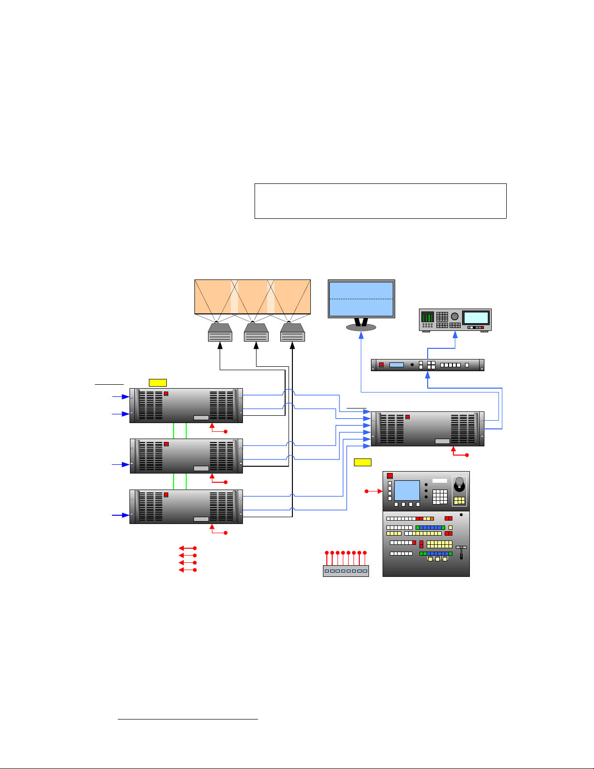
3. Hardware Installation
Installation
tбЗЙ=pЕкЙЙе=`зеСбЦмк~нбзе=mдмл=tбЗЙ=pЕкЙЙе=mкЙобЙп
The figure below illustrates a “triple” wide screen configuration that includes a fourth VP or
VPx, which is used to create a combined wide screen program/preview display.
Please note:
• Because the fourth VP or VPx provides up to 6 PIPs, this procedure is ideal for
displaying a double or triple wide screen configuration on a single monitor.
M/E Inputs
Scaled
Sources
Unscaled
Sources
Unscaled
Sources
Unscaled
Sources
VP #1
VP or VPx #2
VP or VPx #3
Note
This is the only configuration in which a VPx can be used in a
single processor, standalone mode.
• For configurations using more than 3 processors, additional dedicate d “preview”
processors may be required, along with additional monitors.
Projector #1 Projector #2 Projector #3
Widescreen Program
Video Recorder
VP or VPx #4
Note: #1 is VP only, not VPx
Program
Program
Source
Link
Link
Source
Link
Link
PG 2 (Analog)
PG 2 (DVI)
PVW (Analog)
PVW (DVI)
PG 1
PG 2 (Analog)
PG 2 (DVI)
PVW (Analog)
PVW (DVI)
PG 1
PG 2 (Analog)
PG 2 (DVI)
PVW (Analog)
PVW (DVI)
PG 1
Widescreen Preview
Scaler
Inputs
1A
1B
2A
2B
3A
3B
Note: DVI connections only
ImagePRO
PVW
PG 1
To:
Routers
ScreenPRO-II
PresentationPRO-II
ImagePRO
Ethernet Switch
Controller SC or LC
Figure 3-4. Block Diagram, Wide Screen Encore Configuration with Wide Screen Preview
76 Encore Presentation System • User’s Guide • Rev 04
Page 77

3. Hardware Installation
Please note the following points regarding this configuration:
• Processor #4 receives DVI Program and Preview feeds from processors #1, #2
and #3.
• Using Processor #4, three PIPs are scaled and positioned to create the wide
screen Program display, and three more are scaled to create the Preview display.
PIP 1A PIP 2A PIP 3A
Wide Screen
Program
Wide Screen
Preview
PIP 1B PIP 2 B PIP 3B
Figure 3-5. Wide Screen Program/Preview Monitor PIPs
Installation
• Processor #4’s Preview output is routed to the display for viewing the combined
wide screen program/preview output.
• Processor #4’s Program output is routed to an ImagePRO for scaling, and then to
an SDI or HD-SDI recorder. This configuration enables you to record the
combined wide screen program/preview output.
In addition to the equipment listed in
Table 3-5. Equipment List, Additional Wide Screen Program/Preview Requirements
Qty. Item Note
1 VP or VPx Assigned as Video Processor #4
1 DVI or Analog Monitor For wide screen program/preview display
1 Ethernet cable Customer supplied
6 DVI interconnect cables Inputs to video processor #4 (customer supplied)
2 Interconnect cables Video processor #4 outputs (Analog, Video and/or DVI as required)
1 ImagePRO Optional, for use as output scaler (customer supplied)
1 SDI or HD-SDI Video Recorder Optional, to record combined wide screen output (customer supplied)
Use the following steps to install an Encore system that includes a combined wide
screen program/preview display:
1. Follow all steps to install a Wide Screen Encore Application, as outlined in the
“
Wide Screen Configuration” section on page 72. You do not need to inst all the
six individual monitors for program and preview displays, because you will be
using
one monitor instead.
2. Rack mount processor #4.
3. Connect Ethernet from processor #4 to the Ethernet Switch.
Table 3-4 on page 72, you will also need:
Encore Presentation System • User’s Guide • Rev 04 77
Page 78

3. Hardware Installation
Installation
4. Source Connections — connect DVI outputs from processors one, two and three
to processor #4’s scaler inputs:
~ Connect processor #1 DVI Program 2 output to processor #4 input 1A.
~ Connect processor #1 DVI Preview 2 output to processor #4 input 1B.
~ Connect processor #2 DVI Program 2 output to processor #4 input 2A.
~ Connect processor #2 DVI Preview 2 output to processor #4 input 2B.
~ Connect processor #3 DVI Program 2 output to processor #4 input 3A.
~ Connect processor #3 DVI Preview 2 output to processor #4 input 3B.
Note
5. Output Connections —
Program 2 output is used because it is a clean feed, without
any edge feathering or data doubling in the signal.
~ Connect processor #4’s analog or digital Preview Output to the input of
your widescreen preview monitor.
~ (Optional, for video recording) Connect processor #4’s analog or digital
Program Output 1 or 2 to the input of the ImagePRO. Connect the
ImagePRO’s output to the input of your recorder. Refer to the
“
ImagePRO User’s Guide” for connection and setup details.
6. Power Connection — connect AC power cords to the AC Power connectors on
the rear of processor #4, the monitor and the ImagePRO.
7. System ID — Using the Unit ID Selector, set the ID of processor #4 to 4.
Note
8. Power On — all power on instructions are covered in Chapter 6.
With all connections made, continue with Chapter 4, “
page 107.
Each processor must have a unique ID.
Controller Orientation” on
`згйдЙнбеЦ=tбЗЙ=pЕкЙЙе=mкЙобЙп=pЙнмй
Once you are familiar with the Controller, all system setup procedures and basic Encore
operations, you must complete the following operational setup steps — in order to properly
configure processor #4 and its Preview output.
Note
Two different methods are available for connecting processor
sources:
multi-button and single button.
Multi-button method — Use the following steps to complete your wide screen
preview setup, using
1. Set up processor #4 as a unique Encore destination. In Chapter 6, refer to the
Destination Setup” section on page 277.
“
2. On the Controller, identify six buttons on the Source Selection Bus that you want
to use as the inputs from processors 1, 2 and 3.
3. Set up these designated inputs as direct DVI connections. In Chapter 6, refer to
Input Setup” section on page 293 for details.
the “
78 Encore Presentation System • User’s Guide • Rev 04
six individual buttons for processor sources:
Page 79

3. Hardware Installation
Installation
4. Select the destination that you assigned to proces sor #4.
5. Scale and align three PIPs for the “Preview” portion of the display, and three PIPs
for the “Program” portion, as illustrated in
Single-button method — Use the following steps to complete your wide screen
preview setup, using
one button for all six processor sources.
Figure 3-5 on page 77.
Note
1. Set up processor #4 as a unique Encore destination. In Chapter 6, refer to the
“
Destination Setup” section on page 277.
2. On the Controller, identify one button on the Source Selection Bus that you want
to use for all DVI D/A inputs to processor #4.
3. In the Router Specification Menu, create a DVI D/A router. In Chapter 6, refer to
the “
D/A Setup” section on page 274.
4. On the “Number of Outputs” line, specify 6.
5. Using the Output Patch Menu, patch all 6 outputs (from processors 1, 2 and 3) to
processor #4. In Chapter 6, refer to the “
6. Using the Input Patch Menu, select the DVI D/A source button (as identified in
step
2 above), and patch it to the DVI D/A router. In Chapter 6, refer to the “Input
Patching” section on page 275.
7. Select the destination that you assigned to proces sor #4.
8. In the Layer Control Section, select Layer 1A, then select the DVI D/A source.
Be sure to save an input configuration file for this source.
9. Scale and align the first PIP for the “Preview” portion of the display, then repeat
this step for the remaining layers (
reference.
This method sets up a “phantom” DVI D/A router, which takes
advantage of the fact that all processor DVI outputs have
identical resolutions — and thus only one input configuration
file is required. This method only uses one source button on
the Controller, instead of six buttons on the source bus.
Router Setup” section on page 270.
2A through 3B). Use Figure 3-5 on page 77 for
Encore Presentation System • User’s Guide • Rev 04 79
Page 80

3. Hardware Installation
Installation
pбеЦдЙ=pЕкЙЙе=pн~Ев=`зеСбЦмк~нбзе
“Stacking” is a configuration method that provides access to six mixers, with the ability to
display up to 12 PIPs on screen simultaneously. Please note:
• Video Processors (VP) must be used as “master” units in a stack.
• Both VP and VPx units can be used as “slave” units in a wide screen stack.
• Stacking is available for both the Controller SC and LC.
• A stack configuration does not add any additional video delay.
To make 12 PIPs available, processors are combined in pairs. The first processo r’s
Program and Preview outputs are connected to the second processor’s Background (
A and B inputs. In this manner, two “Three M/E” systems are stacked to create a six M/E
processor. Using the six PIPs from each processor, 12 PIPs are available.
BG)
7
8
11
12
2
3
4
5
6
M/E Inputs
Scaled Srcs 7 - 12
(DSK) 1A, 1B
BG Input 3B
BG Input 3A
Note: #2 is VP only
Note: #1 is VP only
PG 1
PG 2 (DVI)
PVW (DVI)
1
2
3
4
5
6
12
10
9
1
VP #2 (3 M/Es)
BG Input B
BG Input A
VP #1 (3 M/Es)
Figure 3-6. Single Screen Stack with 12 PIPs
The figure below illustrates a block diagram of a single screen “stack” configuration. Aux
destinations are not shown. Use this diagram for reference in the following procedure.
VP #2 (ID #2)
VP #1 (ID #1)
Note: #2 is VP only
Top
Stack
Note: #1 is VP only
PG 2
PVW
PG 1
Program
Preview
7
8
9
10
11
Projector
Scaled Srcs 1 - 6
Unscaled Srcs
(BG) 3A, 3B
Routers
ScreenPRO-II
PresentationPRO-II
ImagePRO
Bottom
Stack
To:
Ethernet Switch
PG 2 (DVI)
PVW (DVI)
Controller SC or LC
Figure 3-7. Block Diagram, Single Screen Stack Configuration
80 Encore Presentation System • User’s Guide • Rev 04
Page 81

3. Hardware Installation
For this procedure, you will need:
Table 3-6. Equipment List, Single Screen Stack Configuration
Qty. Item Note
Installation
2 VP Master units (ID#1 and ID#2) must be VP, not VPx. The ID of the bottom
1 Controller Model SC or LC
1 Video Projector Customer supplied
2 DVI or Analog Monitors Program and Preview (customer supplied)
1 Ethernet Switch Customer supplied
3 Ethernet cables Customer supplied. Additional cables required for routers.
2 DVI Interconnect cables Connects bottom stack Processor to top stack Processor
TBD Sources, routers, cables Analog, Video and/or DVI as required (customer supplied)
stack VP must always be lower than the ID of the top stack VP.
Use the following steps to install a single screen “stack” configuration:
Important
1. Follow the unpacking proced ure s as l isted in the “Unpacking and Inspection”
section on page 62.
2. In Appendix A, refer to the “Physical and Electrical Specifications” section on
page 367 for electrical and mechanical details.
3. In Chapter 2, refer to the “Video Processor Rear Panel” section on page 45 and
the “
Controller Rear Panels” section on page 58 for all connector locations.
4. For each VP, follow the rack mount procedures as outlined in the “Rack-Mount
Installation” section on page 62. Remember that Master units (ID#1 and ID#2)
must be VP, not VPx.
5. Ethernet Connections — a totally “local” network connection is recommended.
Using Ethernet cables:
a. Connect the processors and Controll e r to th e Eth e rne t Swi tch .
b. Connect router(s) to the Switch.
c. As required, connect ScreenPRO-II, PresentationPRO-II and ImagePRO
systems to the Switch.
6. Direct Source Connections — if you elect to use direct connections, in place of
(or in addition to) router connections:
a. As an important prerequisite, complete your “Connection Charts” on
page 89 to streamli ne your source installation procedure.
It is recommended that each stack consists of two “fully
loaded” processors, each with three M/Es. If necessary, you
can use a mis-matched configuration (e.g., two M/Es in the
bottom stack, three in the top), but the top stack
must always
have three M/Es installed. In this way, your stacked set will
never have anything less than four M/Es available.
Encore Presentation System • User’s Guide • Rev 04 81
Page 82

3. Hardware Installation
Installation
b. Using the information fro m the chart:
c. Connect unscaled Background sources to the bottom stack:
d. Connect unscaled DSK sources to the top stack:
7. Stack Interconnections —
a.
b. Connect the bottom stack’s DVI Program Output to the top stack’s
8. D/A Connections —
a. If your system includes analog, SDI or DVI D/As, connect video inputs to
b. Connect D/A outputs to the to the desired M/E input connectors.
9. Router Connections — if you elect to use router connections, in place of (or in
addition to) direct connections:
a. For Ethernet controlled routers:
b. To connect a single serial controlled router, use an RS-232 cable to
c. To connect two (or more) serial routers, a third-party Ethernet-to-Serial
d. Ensure that all sources are connected to your ro uter(s).
e. Connect all selected router outputs to the desired M/E inputs:
• Connect “direct” sources 1 - 6 to each M/E’s input connectors
on the “
• Connect “direct” sources 7 - 12 to each M/E’s input connectors
on the “
• Connect background source 1 to input 3A.
• Connect background source 2 to input 3B.
• Connect DSK source 1 to input 1A.
• Connect DSK source 2 to input 1B.
Connect the bottom stack’s DVI Preview Ou tput to the top stack’s
Background 1 input (
Background 2 input (
the D/As as required.
• Ensure that the router(s) are connected to the same Ethernet
Switch as the Controller and processors.
• Ensure that each router has an unique IP address.
connect the router to the Controller’s
refer to the “
converter is required, such as the
UDS2100 (http://www.lantronix.com). Each UDS2100 can control two
serial routers.
• Using RS-232 cables, connect each router to the
• Set up a static IP address on the Lantronix. The recommended
range is
• Using an Ethernet cable, connect the
Ethernet Switch as the Controller and processors.
• For PIPs 1 - 6, connect router outputs to the desired M/E inputs
on the “
• For PIPs 7 - 12, connect router outputs to the desired M/E
inputs on the “
bottom stack” processor.
top stack” processor.
3A).
3B).
EXT COMM port. In Chapter 2,
Controller Rear Panels” section on page 58 for details.
Lantronix model UDS100, UDS200 or
UDS2100.
192.168.0.191 - 192.168.0.240.
UDS2100 to the same
bottom stack” processor.
top stack” processor.
82 Encore Presentation System • User’s Guide • Rev 04
Page 83

3. Hardware Installation
Installation
10. ScreenPRO-II Connections — if your system includes one (or more) destination
ScreenPRO-II units, you can configure the units for internal or external routing:
a. When External routers are used, connect two outputs from an Analog
router to
can also be connected to BNC inputs
specific patches will be defined using the
b. When Internal routing is used, connect Analog sources to inputs 1 - 8 on
the HD-15 connectors, and SDI sources to BNC inputs
setup, these patches will be defined using the
In Chapter 6, see the “
11. Output Connections — all output monitor and projector connections originate
from the “
top stack” processor:
a. Connect the analog or digital Preview Output to the input of the
associated Preview Monitor.
b. Connect the analog or digital Program 2 Output to the input of the
associated Program Monitor.
c. Connect the analog or digital Program 1 Output to the input of the
associated projector.
d. Connect the Program Out HD/SDI connector to an SDI or HDTV monitor
as required, or to the proper video distribution equipment.
any two HD-15 inputs on the ScreenPRO-II. An SDI router
1 and 2. During setup, these
Output Patch Menu.
1 and 2. During
Input Patch Menu.
ScreenPRO-II Destination Setup” section for details.
Note
e. If you elect to output in an interlaced format (e.g., 1920 x 1080i), connect
the top stack’s
Analog
Note
12. Aux Destinations — you can configure three types of Aux destinations: Aux
(monitors),
“
Working With Destinations” on page 393 for interconnection details.
13. Power Connection — connect AC to all Encore and peripheral equipment.
14. Tally Connection — the Controller provides one 25-pin D connector for issuing
“relay closure” commands to external devices. Eight circuits are provided. In
Appendix A, refer to the “
15. System ID — Using the Unit ID Selector, set the ID of the bottom stack
processor (VP only) to
ImagePRO Aux and PresentationPRO-II Aux. Refer to Appendix D,
Important
This output only works if the selected output resolution is a
valid SDI or HD/SDI format.
H Sync Output signal (located on the Program 2 Out
connector) to the Genlock input on the bottom stack.
Using a VGA to 5xBNC breakout cable, the H Sync Output
line is typically a white or gray cable.
Tally Connector” section on page 374 for details.
1. Set the ID of the top stack processor to 2 (VP or VPx).
The ID of the bottom stack processor mu st always be lower
than the ID of the top stack processor. Remember that
Master units (ID#1 and ID#2) must be VP , not VPx.
16. Power On — all power on instructions are covered in Chapter 6.
Continue with Chapter 4, “
Encore Presentation System • User’s Guide • Rev 04 83
Controller Orientation” on page 107.
Page 84
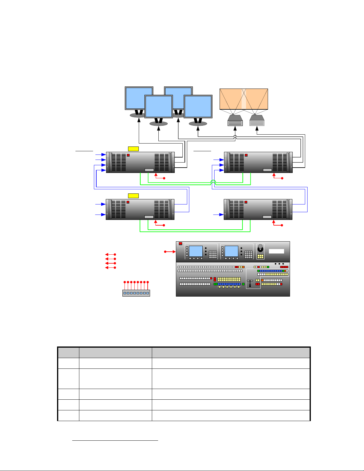
3. Hardware Installation
Installation
tбЗЙ=pЕкЙЙе=pн~Ев=`зеСбЦмк~нбзе
The figure below illustrates a block diagram of a wide screen “stack” configuration. Aux
destinations are not shown. Use this diagram for reference in the following procedure.
Program #1 Program #2
Projector #1 Projector #2
Preview #1 Preview #2
M/E Inputs VP #2 (ID #2)
Scaled Sources 7 - 12
Unscaled Srcs (DSK) 1A, 1B
Background (BG) Input 3B
Background (BG) Input 3A
Scaled Sources 1 - 6
Unscaled Sources
(Backgrounds) 3A, 3B
ScreenPRO-II
PresentationPRO-II
Routers
ImagePRO
M/E Inputs VP or VPx #4 (ID #4)
(DSK) 1A, 1B
BG Input 3B
BG Input 3A
Program Link
Source Link
(Backgrounds)
3A, 3B
Program Link
Source Link
To:
VP #1 (ID #1)
Note: #2 is VP only
Top
Stack
#1
Note: #1 is VP only
Bottom
Stack
#1
Ethernet Switch
PG 2
PVW
PG 1
PG 2 (DVI)
PVW (DVI)
Figure 3-8. Block Diagram, Wide Screen Stack Configuration
VP or VPx #3 (ID #3)
Controller SC or LC
Top
Stack
#2
Bottom
Stack
#2
PG 2
PVW
PG 1
PG 2 (DVI)
PVW (DVI)
For this procedure, you will need:
Table 3-7. Equipment List, Wide Screen Stack Configuration
Qty. Item Note
2 VP Master units (ID#1 and ID#2) must be VP, not VPx.
2 VP or VPx The ID of the bottom stack processor must always be lower than the ID
of the top stack processor. Use 6 total processors for triple wide
screen, use 8 for quadruple wide, etc.
1 Controller Model SC or LC
2 Video Projectors Customer supplied
4 DVI or Analog Monitors Program and Preview (customer supplied)
84 Encore Presentation System • User’s Guide • Rev 04
Page 85

3. Hardware Installation
Table 3-7. Equipment List, Wide Screen Stack Configuration (Continued)
Qty. Item Note
1 Ethernet Switch Customer supplied
5 Ethernet cables Customer supplied. Additional cables required for routers.
Installation
TBD Program Link Cables (DVI-I) Use 2 for double wide screen application,
Use 4 for triple wide screen application, left justification
Use 4 for double wide screen application, center justification
Use 6 for triple wide screen application, center justification
TDB Source Link Cables (DVI-I) Minimum 4 for double wide screen application.
TBD Sources, routers, cables Analog, Video and/or DVI as required (customer supplied)
left justification
Use the following steps to install a wide screen “stack” configuration:
Important
1. Follow the unpacking proced ure s as l isted in the “Unpacking and Inspection”
section on page 62.
2. In Appendix A, refer to the “Physical and Electrical Specifications” section on
page 367 for electrical and mechanical details.
3. In Chapter 2, refer to the “Video Processor Rear Panel” section on page 45 and
Controller Rear Panels” section on page 58 for all connector locations.
the “
4. For each processor, follow the rack mount procedures as outlined in the “Rack-
Mount Installation” section on page 62. Remember that master units (ID#1 and
ID#2) must be VP, not VPx.
5. Ethernet Connections — a totally “local” network connection is recommended.
Using Ethernet cables:
a. Connect the processors and Controll e r to th e Eth e rne t Swi tch .
b. Connect router(s) to the Switch.
c. As required, connect ScreenPRO-II, PresentationPRO-II and ImagePRO
systems to the Switch.
6. Direct Source Connections — if you elect to use direct connections, in place of
(or in addition to) router connections:
a. As an important prerequisite, complete your “Connection Charts” on
page 89 to streamli ne the source installation procedure.
b. Using information from the charts, connect the desired “direct” sources to
each M/E’s input connectors on each stack. Note that in a wide screen
stack system, scaled sources only connect to stack #1. The “link”
connections carry the signals to the other stacks:
It is recommended that each stack consists of two “fully
loaded” processors, each with three M/Es. If necessary, you
can use a mis-matched configuration (e.g., two M/Es in the
bottom stack, three in the top), but the top stack
have three M/Es installed. In this way, your stacked set will
never have anything less than four M/Es available.
must always
Encore Presentation System • User’s Guide • Rev 04 85
Page 86

3. Hardware Installation
Installation
c. Unscaled Backgrounds must originate from computers with multi-head
• On stack #1 only, connect “direct” sources 1 - 6 to each M/E’s
input connectors on the “
• On stack #1 only, connect “direct” sources 7 - 12 to each M/E’s
input connectors on the “
graphics cards, and connect to the same input on each “bottom stack”
processor.
bottom stack” processor.
top stack” processor.
S To connect an unscaled background source in a double widescreen
stack system (each processor with three M/Es):
• On the first stack, connect the computer’s “head 1” to the
bottom stack processor, input 3A
• On the second stack, connect the computer’s “head 2” to the
bottom stack processor, input 3A
Note
d. The DSK source may originate from a computer with a multi-head
graphics card, but it is not a requirement.
Input 3A resides on the lowest priority M/E in a 3 M/E system.
To connect a
both stacks.
second background source, use input 3B on
S Connecting a single-head graphics card to processor 4 only would
Note
enable a bug to be placed
The DSK Setup Menu allows you to pick an individual ID
within a widescreen on which to perform DSK setup.
If you elect to use a multi-head graphics card for the DSK, ensure that
you connect to the same input on each processor — to the highest
priority M/E.
only in that screen space.
S To connect an unscaled DSK source in a double widescreen stack
system (each processor with three M/Es):
• On the first stack, connect the computer’s “head 1” to the top
stack processor, input 1A
• On the second stack, connect the computer’s “head 2” to the
top stack processor, input 1A
Note
7. Stack Interconnections —
a.
On the first stack:
86 Encore Presentation System • User’s Guide • Rev 04
Input 1A resides on the highest priority M/E in a 3 M/E Encore
system. If you wish to connect a backup (or alternate) DSK,
use input 1B on both stacks.
• Connect the bottom stack’s
stack’s Background 1 input (
• Connect the bottom stack’s
stack’s Background 2 input (
DVI Preview Output to the top
3A).
DVI Program Output to the top
3B).
Page 87

3. Hardware Installation
Installation
b. On the second stack:
• Connect the bottom stack’s
stack’s Background 1 input (
• Connect the bottom stack’s
stack’s Background 2 input (
8. D/A Connections —
a.
If your system includes analog, SDI or DVI D/As, connect video inputs to
the D/As as required.
b. Connect D/A outputs to the to the desired M/E input conne ctors on the
first stack only.
9. Router Connections — if you elect to use router connections, in place of (or in
addition to) direct connections:
a. For Ethernet controlled routers, ensure that they are connected to the
same Switch as the Controller and processors. Ensure that each router
has an unique IP address.
b. To connect a single serial controlled router, use an RS-232 cable to
connect the router to the Controller’s
refer to the “
c. To connect two (or more) serial routers, a third-party Ethernet-to-Serial
converter is required, such as the
UDS2100 (http://www.lantronix.com). Each UDS2100 can control two
serial routers.
• Using RS-232 cables, connect each router to the
• Set up a static IP address on the Lantronix. The recommended
• Using an Ethernet cable, connect the
d. Ensure that all sources are connected to your ro uter(s).
e. Connect all selected router outputs to the desired M/E inputs on the first
stack only:
• For PIPs 1 - 6, connect router outputs to the desired M/E inputs
• For PIPs 7 - 12, connect router outputs to the desired M/E
f. If your configuration includes one (or more) destination ScreenPRO-II
units, connect two outputs from each router to each ScreenPRO-II.
10. ScreenPRO-II Connections — if your system includes one (or more) destination
ScreenPRO-II units, you can configure them for internal or external routing:
a. When External routers are used, connect two outputs from an Analog
router to
also be connected to BNC inputs
patches will be defined using the
b. When Internal routing is used, connect Analog sources to inputs 1 - 8 on
the HD-15 connectors, and SDI sources to BNC inputs
setup, these patches will be defined using the
In Chapter 6, see the “
Controller Rear Panels” section on page 58 for details.
range is
with other devices.
Ethernet Switch as the Controller and processors.
on the “
inputs on the “
any two HD-15 inputs on ScreenPRO-II. An SDI router can
192.168.0.191 - 192.168.0.240 — so as not to conflict
bottom stack” processor.
top stack” processor.
ScreenPRO-II Destination Setup” section for details.
DVI Preview Output to the top
3A).
DVI Program Output to the top
3B).
EXT COMM port. In Chapter 2,
Lantronix model UDS100, UDS200 or
UDS2100.
UDS2100 to the same
1 and 2. During setup, these specific
Output Patch Menu.
1 and 2. During
Input Patch Menu.
Encore Presentation System • User’s Guide • Rev 04 87
Page 88

3. Hardware Installation
Installation
11. Output Connections — all output monitor and projector connections originate
from the “
a. On each “top stack” processor, connect the analog or digital Preview
b. On each “top stack” processor, connect the analog or digital Program 2
c. On each “top stack” processor, connect the analog or digital Program 1
d. Connect the “top stack” Program Ou t HD/SDI connector to an SDI or
top stack” processors:
Output to the input of the associated Preview Monitor.
Output
to the input of the associated Program Monitor.
Output to the input of the associated projector.
HDTV monitor, or to the proper video distribution equipment.
Note
e. If you elect to output in an interlaced format (e.g., 1920 x 1080i), connect
each top stack’s
Analog connector) to the Genlock input on the bottom stack.
Note
12. Aux Destinations — you can configure three types of Aux destinations: Aux
(monitors),
Working With Destinations” on page 393 for interconnection details.
“
13. Link Connections — in a widescreen application, the Program Link and Source
Link
inputs and outputs for the proper “overlap” between projectors. Refer to the
“
Program and Source Link Connections” section on page 98 for instructions.
14. Power Connection — connect AC power cords to all Encore and periphe ral
equipment, and then to AC outlets.
15. Tally Connection — the Controller provides one 25-pin D connector for issuing
“relay closure” commands to external devices. Eight circuits are provided. In
Appendix A, refer to the “
16. System ID — Using the Unit ID Selector:
ImagePRO Aux and PresentationPRO-II Aux. Refer to Appendix D,
connections (DVI-I) are used to connect processors together, and bridge
a. On the first stack, set the ID of the bottom stack Processor to 1 (VP only)
Set the ID of the top stack Processor to
b. On the second stack, set the ID of the bottom stack Processor to 3 (VP
or VPx). Set the ID of the top stack Processor to
This output only works if the selected output resolution is a
valid SDI or HD/SDI format.
H Sync Output signal (located on the Program 2 Out
Using a (customer supplied) VGA to 5xBNC breakout cable,
H Sync Output line is typically a white or gray cabl e .
the
Tally Connector” section on page 374 for details.
2 (VP or VPx).
4 (VP or VPx).
Important
17. Power On — all power on instructions are covered in Chapter 6.
Continue with Chapter 4, “
88 Encore Presentation System • User’s Guide • Rev 04
In each stack, the ID of the bottom stack Processor must
always be lower than the ID of the top stack Processor.
Remember that master units (ID#1 and ID#2) must be VP
only, not VPx.
Controller Orientation” on page 107.
Page 89

`зееЙЕнбзе=`Ь~кнл=
A series of Connection Charts are provided on the following pages to assist with your
input connections. The following topics are discussed:
• Connection Overview
• Chart Instructions
• Sample Connection Charts
• Blank Connection Charts
`зееЙЕнбзе=lоЙкобЙп
Please remember the following important points regarding system interconnection:
• Each M/E has two scalers, each with three inputs: Analog, HD/SDI and DVI-I.
The DVI-I connector has both an
3. Hardware Installation
Connection Charts
analog and a digital connection.
Note
The analog connection on the DVI connector can only be
used for unscaled inputs. It cannot be sent to the scaler. The
digital side can go to either the scaled or unscaled channel.
• You can connect sources and assign them to Controll er buttons — but only one
source can be assigned to a scaler at a time. For unscaled sources, connect a
maximum of two backgrounds and two DSK sources.
Note
Two DSK sources can be connected to the system on 1A and
1B — but only one can be used at a time.
• You can connect a source directly to an input, or you can connect the output of a
router to an input. The use of routers offers less restrictions with regard to
assigning sources to layers.
• Analog inputs can be used to connect composite, S-Video (Y/C) and component
video sources. Customer supplied breakout cables are required.
• The DSK source always connects to one of the two DVI-I inputs on the M/E 1
board — electronically, the highest priority board in the system.
• Background sources always connect to the lowest priority board in your system,
but that board varies depending upon the number of M/E boards present. In
Chapter 2, see the “
A Word About M/E Connector Priority” section on page 50.
• Remember that VPx is designed for widescreen and stack configurations. A VPx
cannot be used in a single processor configuration.
Encore Presentation System • User’s Guide • Rev 04 89
Page 90

3. Hardware Installation
Connection Charts
`Ь~кн=fелнкмЕнбзел
Following are instructions for using the connection charts:
• Router I/O Charts
Complete one chart for each video router in your system (up to the maximum 8).
~ Column 1: list the sources that are connected to the router inputs.
~ Column 2: list the Encore button(s) to which the source will be patched.
~ Column 4: list where each router output will be connected.
Note
The router charts can also be used for D/A connections.
• Direct Encore Input Chart
Complete the chart for any sources that will be connected directly to Encore.
~ Column 1: list the direct connection source name.
~ Column 2: list the Encore button(s) to which the source will be patched.
~ Column 3: list the VP or VPx to which the source is connected.
~ Column 4: list the specific M/E input (and format) to which the source is
connected: DVI, HD-SDI or Analog.
• Encore Destination Chart
Complete the chart for all Encore destinations.
~ Column 1: list the VP(s) or VPx(s) that comprise the destination.
~ Column 2: list the Encore destination assignment.
~ Column 3: list the screen to which the destination is routed.
~ Column 4: list any notes as necessary.
90 Encore Presentation System • User’s Guide • Rev 04
Page 91

3. Hardware Installation
Connection Charts
p~гйдЙ=`зееЙЕнбзе=`Ь~кнл
Following are sample connection charts for an Encore system comprised of 1 x analog
router, 2 x direct inputs, and 6 x destinations.
Table 3-8. Router I/O Chart #1 (sample)
Router #1 Router Type: x Analog Digital DVI
Source Name Encore Input # Router Input/Output Connects to:
DVD A 1 / 33 1 VP 1 - 1A
DVD B 2 / 34 2 VP 1 - 1B
Flash CPU 3
Multi A 4
Multi B 5 6 VP 1 - 3B
Multi C 6
Multi D 7 / 39 8 ScreenPRO 5 - In 2
Key Dell 1 8
Key Dell 2 9 10 VP 3 - 2B
ImagePRO 2 13
ImagePRO 1 14 14 ImagePRO 2 - In 3
ScreenPRO 2 Preview 15
BEM CPU 16 16 Bottom LC40
3 VP 1 - 2A
4 VP 1 - 2B
5 VP 1 - 3A
7 S creenPRO 5 - In 1
9 VP 3 - 2A
11 VP 3 - 3A
12 VP 3 - 3B
13
15 ImagePRO 1 - In 2
Table 3-9. Direct Encore Input Chart (sample)
Direct Encore Inputs
Source Name Encore Input # Video Processor Encore Port
Comp 1 59 1 1A, DVI
Comp 2 60 1 1B, DVI
Table 3-10. Encore Destination Chart (sample)
Destination Device Screen Notes
1 VP 1, VP 2 FLM Wide DVI to FLM L and R
2 VP 3 XLM Single DVI to XLM
3 VP 4 LC 40 Top Pvw / Pgm Monitor
4 ImagePRO 1 Any A-14, HD-16, D-1
Controller SC
5 SP 5 FLM Single
6 Router Aux 12 Downstage Mon
Encore Presentation System • User’s Guide • Rev 04 91
Page 92

3. Hardware Installation
Connection Charts
_д~ев=`зееЙЕнбзе=`Ь~кнл=
The following blank connection charts are provided:
• Router I/O Charts
• Direct Encore Input Chart
• Encore Destination Chart
oзмнЙк=fLl=`Ь~кнл=
Complete one chart for each video router in your system. Encore supports up to eight
routers. Note that these charts can also be used for D/As.
Table 3-11. Router I/O Chart #1
Router #1 Router Type: Analog Digital DVI
Source Router Input/Output Destination
1
2
3
4
5
6
7
8
9
10
11
12
13
14
15
16
92 Encore Presentation System • User’s Guide • Rev 04
Page 93

3. Hardware Installation
Connection Charts
Table 3-12. Router I/O Chart #2
Router #2 Router Type: Analog Digital DVI
Source Router Input/Output Destination
1
2
3
4
5
6
7
8
9
10
11
12
13
14
15
16
Table 3-13. Router I/O Chart #3
Router #3 Router Type: Analog Digital DVI
Source Router Input/Output Destination
1
2
3
4
5
6
7
8
9
10
11
12
13
14
15
16
Encore Presentation System • User’s Guide • Rev 04 93
Page 94

3. Hardware Installation
Connection Charts
Table 3-14. Router I/O Chart #4
Router #4 Router Type: Analog Digital DVI
Source Router Input/Output Destination
1
2
3
4
5
6
7
8
9
10
11
12
13
14
15
16
Table 3-15. Router I/O Chart #5
Router #5 Router Type: Analog Digital DVI
Source Router Input/Output Destination
1
2
3
4
5
6
7
8
9
10
11
12
13
14
15
16
94 Encore Presentation System • User’s Guide • Rev 04
Page 95

3. Hardware Installation
Connection Charts
Table 3-16. Router I/O Chart #6
Router #6 Router Type: Analog Digital DVI
Source Router Input/Output Destination
1
2
3
4
5
6
7
8
9
10
11
12
13
14
15
16
Table 3-17. Router I/O Chart #7
Router #7 Router Type: Analog Digital DVI
Source Router Input/Output Destination
1
2
3
4
5
6
7
8
9
10
11
12
13
14
15
16
Encore Presentation System • User’s Guide • Rev 04 95
Page 96

3. Hardware Installation
Connection Charts
Table 3-18. Router I/O Chart #8
Router #8 Router Type: Analog Digital DVI
Source Router Input/Output Destination
1
2
3
4
5
6
7
8
9
10
11
12
13
14
15
16
aбкЙЕн=bеЕзкЙ=fеймн=`Ь~кн=
Complete the following chart for any sources that will be connected directly to Encore (such
as a computer for a DVI background).
Table 3-19. Direct Encore Input Chart
Direct Encore Inputs
Source Video Processor Encore Port
96 Encore Presentation System • User’s Guide • Rev 04
Page 97

3. Hardware Installation
bеЕзкЙ=aЙлнбе~нбзе=`Ь~кн=
Complete the following chart for all Encore destinations.
Table 3-20. Encore Destination Chart
Destination Device Screen Notes
1
2
3
4
Controller SC
Controller LC
5
6
7
8
9
10
11
12
13
14
15
16
17
18
19
20
21
22
23
24
25
26
27
28
29
30
31
32
Connection Charts
Encore Presentation System • User’s Guide • Rev 04 97
Page 98

3. Hardware Installation
Program and Source Link Connections
mкзЦк~г=~еЗ=pзмкЕЙ=iбев=`зееЙЕнбзел
The following topics are discussed in this section:
• Overview of Edge-Blending Technology
• Connecting Program and Source Links
lоЙкобЙп=зС=bЗЦЙJ_дЙеЗбеЦ=qЙЕЬездзЦу
Edge-blending technology is becoming increasingly popular for supporting very large highresolution displays. The technology is very flexible and supports a wide range of screen
configurations. A typical three projector system is illustrated below. As shown in the figure,
multiple projectors are used to project on a common surface to create one high-resolution
image. The creation of a seamless image requires careful attention to detail. High quality
results are dependent upon a system-level approach that integrates content creation, video
processing, projector setup and system adjustments as described below.
Adjustable
Image Overlap
Projector #1
Output
Figure 3-9. Typical three projector system
Projector #2
Output
Projector #3
Output
`зенЙен=`кЙ~нбзе=
When projecting an image across a large screen, it is important to maintain sufficient
resolution to obtain a crisp, clear image from the perspective of the viewer. Generally, highresolution source material is used to maintain content that is pleasing to the eye. There are
two methods that are commonly used to generate wide-screen source material, each of
these methods is explained below.
• Use of a Single High Definition Image
High Definition source material has a resolution of 1920 pi xels x 1080 lines.
Images of this type can be reformatted to drive multiple screens. The reformatting
is usually performed by a seamless switching system such as the Encore
Presentation System.
Reformatting allows the resultant images to be processed for providing seamless
switching, integration of picture-in-picture video and keying features. Note that
the input image can be effectively spread to multiple screens, however, the
98 Encore Presentation System • User’s Guide • Rev 04
Page 99

HDTV Image
1920 x 1080
Image for
Projector 1
1280 x 1024
3. Hardware Installation
Program and Source Link Connections
inherent resolution of the output image remains that of the source material,
1920x1080 pixels.
1920
bеЕзкЙ
1080
1280
båÅç
1024
Image for
Projector 2
1280 x 1024
1280
ÅçêÉ
1024
1920
bеЕзкЙ
1024
1 2
Figure 3-10. HD Source Material Formatting
• Use Of Multi-Head Graphics Board s
Standard multi-head graphics boards can be used to directly generate image data
to drive multiple screens. In this case, the computer generates one very highresolution image and the image is output by multiple graphics heads. The inherent
resolution of the output image is limited only by the processing power of the multihead graphics board. Image resolutions with up to 10,000 pixels of horizontal
resolution can be achieved with current technology.
Encore Presentation System • User’s Guide • Rev 04 99
Page 100
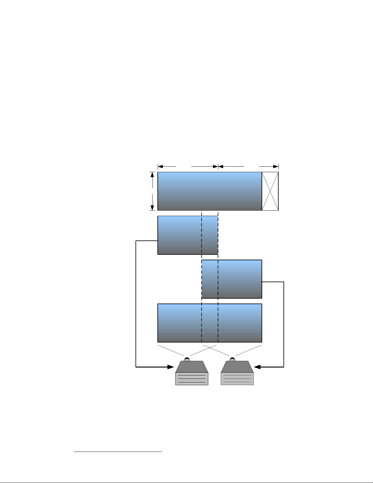
3. Hardware Installation
Program and Source Link Connections
sбЗЙз=mкзЕЙллбеЦ
The purpose of the edge-blending process is to provide a smooth transition for the eye over
the blending region. To provide a smooth transition, identical image data from two different
projectors must be superimposed and the output from each projector must be edge
feathered to provide seamless optical mixing of the two source images. There are two
video processing functions that are required specifically to support wide-screen edge
blended displays:
• Image Overlap
Source images consist of a single HD image that has been split into multiple
channels, or a series of images from a multi-head graphics card. In either case,
the source images must be re-formatted to provide image overlap to support the
edge-blending process. The Image Overlap processing is illustrated below. The
width of the blending region determines the amount of required image overlap and
this must be programmable to support different applications.
Original Image from
Multi-head Graphics Card
Image Overlap and Edge Feathering.
1280 1280
1024
bеЕзкЙ
Image for
Projector 1
båÅç
Image
Overlap
Region
ÅçêÉ
bеЕзкЙ
1 2
Unused
Source
Material
Image for
Projector 2
Figure 3-11. Image Overlap and Data Doubling
100 Encore Presentation System • User’s Guide • Rev 04
 Loading...