

Page 1
MDSC-2226
User Guide
Page 2

Page 3

MDSC-2226
User Guide
(451920610993)K5903021/02
01/03/2013
Page 4

Barco nv
President Kennedypark 35, 8500 Kortrijk, Belgium
Phone: +32 56.23.32.11
Fax: +32 56.26.22.62
Support: www.barco.com/esupport
Visit us at the web: www.barco.com
PrintedinBelgium
Page 5

Table of contents
TABLE OF CONTENTS
1. Welcome! ......... ............................................................ ..................... 3
1.1 About the product ............................................................................................. 3
1.2 Symbols........................................................................................................ 4
1.3 What’s in the box.............................................................................................. 4
1.4 About this user guide ......................................................................................... 4
2. Parts, controls and connectors .................................. ............................. 5
2.1 Front view...................................................................................................... 5
2.2 Rear view ............. ................ ................ ................ ................ ................ ......... 6
2.3 Connector view................................................................................................ 6
2.3.1 MDSC-2226 LED version.................... ................ ................ ................ ........... 6
2.3.2 MDSC-2226 DDI version ............................................................................... 7
2.3.3 MDSC-2226 MNA version.............................................................................. 8
2.4 Connector pin assignments .................................................................................. 9
2.4.1 Input power connector .................................................................................. 9
2.4.2 DVI–1 connector......................................................................................... 9
2.4.3 DVI-2 connector .........................................................................................10
2.4.4 DVI out connector .......................................................................................11
2.4.5 RS232 connector ............. .................. ................ ................ ................ .........11
2.4.6 USB connector.......... ................ ................ ................ ................ ................ .12
2.4.7 Mini USB connector .......... ................ ................ ................ ................ ...........12
2.4.8 DisplayPort connector ......... ................ ................ ................ ................ .........12
2.4.9 S-Video and S-Video-out connector ...................................................................13
3. Display installation ................... ........................................................... 15
3.1 VESA mount installation......................................................................................15
3.2 Cover removal.................................................................................................16
3.3 Video input connection .... ................ ................ ................ ................ .................. .16
3.3.1 MDSC-2226 LED version.................... ................ ................ ................ ...........16
3.3.2 MDSC-2226 DDI version ...............................................................................17
3.3.3 MDSC-2226 MNA version..............................................................................17
3.4 Video output connection......................................................................................18
3.4.1 MDSC-2226 LED version.................... ................ ................ ................ ...........18
3.4.2 MDSC-2226 DDI version ...............................................................................19
3.4.3 MDSC-2226 MNA version..............................................................................20
3.5 Nexxis OR .....................................................................................................20
3.6 Power supply connection.....................................................................................20
3.7 Cable routing ........... ................ ................ ................ ................ .................. .....21
4. Daily operation ......... .................................................................... ...... 23
4.1 Keyboard backlight ............ ................ ................ ................ .................. .............23
4.2 On/Off switching...................... ................ ................ .................. ................ .......23
4.3 OSD menu activation .............. ................ ................ ................ ................ ...........23
4.4 OSD menu navigation ..... ................ ................ ................ .................. ................ .24
4.5 Shortkey functions ............................................................................................25
4.5.1 Main source selection...................................................................................26
4.5.2 Multi-image configuration.................. ................ ................ ................ .............26
4.5.3 Zoom factor selection .......... ................ ................ ................ ................ .........26
4.5.4 Brightness adjustment ..................................................................................26
4.6 Extended keyboard functions................................................................................27
4.6.1 Main source selection...................................................................................28
4.6.2 Second source selection................. .................. ................ ................ .............28
4.6.3 Multi-image configuration.................. ................ ................ ................ .............29
4.6.4 Transfer function selection .............................................................................29
4.6.5 Image size selection ............... ................ ................ ................ .................. ...29
4.6.6 Zoom factor selection .......... ................ ................ ................ ................ .........30
4.7 Keyboard locking/unlocking..................................................................................30
(451920610993)K5903021 MDSC-2226 01/03/2013
1
Page 6

Table of contents
5. Advanced operation .................. ........................................................... 33
5.1 OSD picture menu ............................................................................................33
5.1.1 Profile.. ................ ................ ................ ................ ................ .................. .33
5.1.2 Brightness........... ................ ................ ................ .................. ................ ...33
5.1.3 Contrast ..... .................. ................ ................ ................ ................ ...........34
5.1.4 Saturation . ................ ................ ................ ................ ................ ............... 34
5.1.5 Color temperature .......................................................................................34
5.1.6 Gamma.......... ................ ................ ................ ................ ................ .........35
5.1.7 Sharpness..... ................ ................ ................ ................ ................ ...........35
5.2 Picture Advanced menu......................................................................................36
5.2.1 Black Level...............................................................................................36
5.2.2 Smart Video..... ................ ................ ................ ................ ................ .........36
5.2.3 Image Position........ ................ ................ ................ ................ ................ ...36
5.2.4 Auto Adjustment ............ ................ ................ ................ ................ .............37
5.2.5 Phase.....................................................................................................37
5.2.6 Clock/Line................................................................................................37
5.3 Display Format menu...... ................ ................ ................ ................ ................ ...38
5.3.1 Main Source (Primary Source).........................................................................38
5.3.2 Component Mode ............ .................. ................ ................ ................ .........38
5.3.3 Zoom................. ................ ................ ................ ................ ................ .....39
5.3.4 Image Size ...... ................ ................ ................ ................ ................ .........39
5.3.5 2
5.3.6 2
5.3.7 2
5.3.8 Picture Swap...................... ................ ................ ................ ................ .......41
5.4 Configuration menu ...........................................................................................42
5.4.1 Information ...... ................ ................ ................ ................ ................ .........42
5.4.2 Language.................................................................................................42
5.4.3 Failover mode....... ................ ................ ................ ................ ................ .....43
5.4.4 Extended keyboard......................................................................................43
5.4.5 OSD setting ..............................................................................................43
5.4.6 Recall Profile...... ................ ................ ................ ................ ................ .......44
5.4.7 Save Profile ..............................................................................................45
5.5 System menu..................................................................................................45
5.5.1 Power on DVI 1..........................................................................................45
5.5.2 Power on DVI 2..........................................................................................46
5.5.3 DVI Output ................ ................ ................ .................. ................ .............46
5.5.4 Keyboard lock............................................................................................46
5.5.5 Keyboard backlight....... ................ ................ ................ ................ ............... 47
5.5.6 Power Saving ............................................................................................47
nd
Picture Mode ........... ................ ................ ................ ................ .............40
nd
Picture Source.......................................................................................40
nd
Picture Position..... ................ ................ ................ ................ ................ .41
5.4.5.1 OSD Horizontal Position ..........................................................................43
5.4.5.2 OSD Vertical Position .... .................. ................ ................ ................ .......44
5.4.5.3 OSD Time-out......................................................................................44
6. Important information ......... .................................................................. 49
6.1 Safety information...... .................. ................ ................ ................ ................ .....49
6.2 Environmental information ...................................................................................51
6.3 Biological hazard and returns..................... ................ ................ ................ ...........53
6.4 Regulatory compliance information ...... ................ ................ ................ .................. .54
6.5 Cleaning and disinfection ....................................................................................54
6.6 Explanation of symbols................ ................ ................ ................ ................ .......55
6.7 Legal disclaimer...............................................................................................56
6.8 Technical specifications ......................................................................................56
6.9 Warranty statement ........ ................ ................ ................ ................ ................ ...59
6.10 Open source license information ............................................................................63
2
(451920610993)K5903021 MDSC-2226 01/03/2013
Page 7

1. Welcome!
1. WELCOME!
1.1 About the product
Overview
Barco’s MDSC-2226 is a 26-inch surgical display. Purpose-built for the operating room, the MDSC-2226
offers an easy-clean design, smart mechanics and the most detailed images in the operating room today.
Ease of mind
Perfect hand-eye coordination: The display’s high brightness, high contrast and full HD resol
surgeons with excellent depth perception and the most accurate images. The MDSC-2226 presents images with unrivaled color and grayscale accuracy and with near-zero latency, making it perfectly suited
for use with today’s state-of-the-art endoscopy camera systems.
Multi-source, multi-display imaging: With its broad input connectivity, the MDSC-2226 also offers flexible
multi-modality imaging (PiP & PaP) in new integrated operating rooms. Thanks to its high-bright LED
backlight, the surgical display also ensures a long lifetime and low power consumption.
ution provide
Ease of installation
The MDSC-2226 comes with a smart cable management system that hides the cables for a clutter-free
set-up. Its lightweight design allows easy mounting on surgical booms and spring arms. Available in three
models, this surgical display also features a host of connectivity options and remote control.
Ease of use
Barco’s MDSC-2226 allows easy cleaning and complete disinfection thanks to its smooth surface, sealed
housing, and protective screen cover. The fanless design avoids the spread of contaminants.
Features
• 26-inch wide-screen LCD with full HD resolution and 10–bit per color
• Wide viewing angle
• High-brightness LED backlight
• Backlight Output Stabilization (BLOS)
• Advanced, full 10-bit image processing algorithms with 12–bit LUT
• Widest range of SD and HD input signals, including 3G-SDI and DisplayPort
• Light weight to easily mount onto a boom
Innovative features are also available to give maximum flexibility when installing the display as: Configurable DVI-out and Failover Mode
(451920610993)K5903021 MDSC-2226 01/03/2013
3
Page 8
1. Welcome!
1.2 Symbols
Overview
The following icons are used in the manual :
Caution
Warning
Info, term definition. General info about the term
Note: gives extra information about the described subject
Tip: gives extra advice about the described subject
1.3 What’s in the box
Overview
Your MDSC-2226 display comes with:
• MDSC-2226 user guide
•DVIcable
• AC power cords
• external power supply
• 4 screws and Allen key
Keep y our original packaging. It is designed for this display and is the ideal protection
during transport.
1.4 About this user guide
Overview
This manual provides a support to the user during the ins
display. Depending on the specific version that has been purchased, some of the features and options
described in this document may not apply to the display in user’s hands.
tallation, set up and utilization of the MDSC-2226
4
(451920610993)K5903021 MDSC-2226 01/03/2013
Page 9
2. Parts, controls and connectors
2. PARTS, CONTROL S AND
CONNECTORS
2.1 Front view
Overview
1
2
3 4 5 6 7
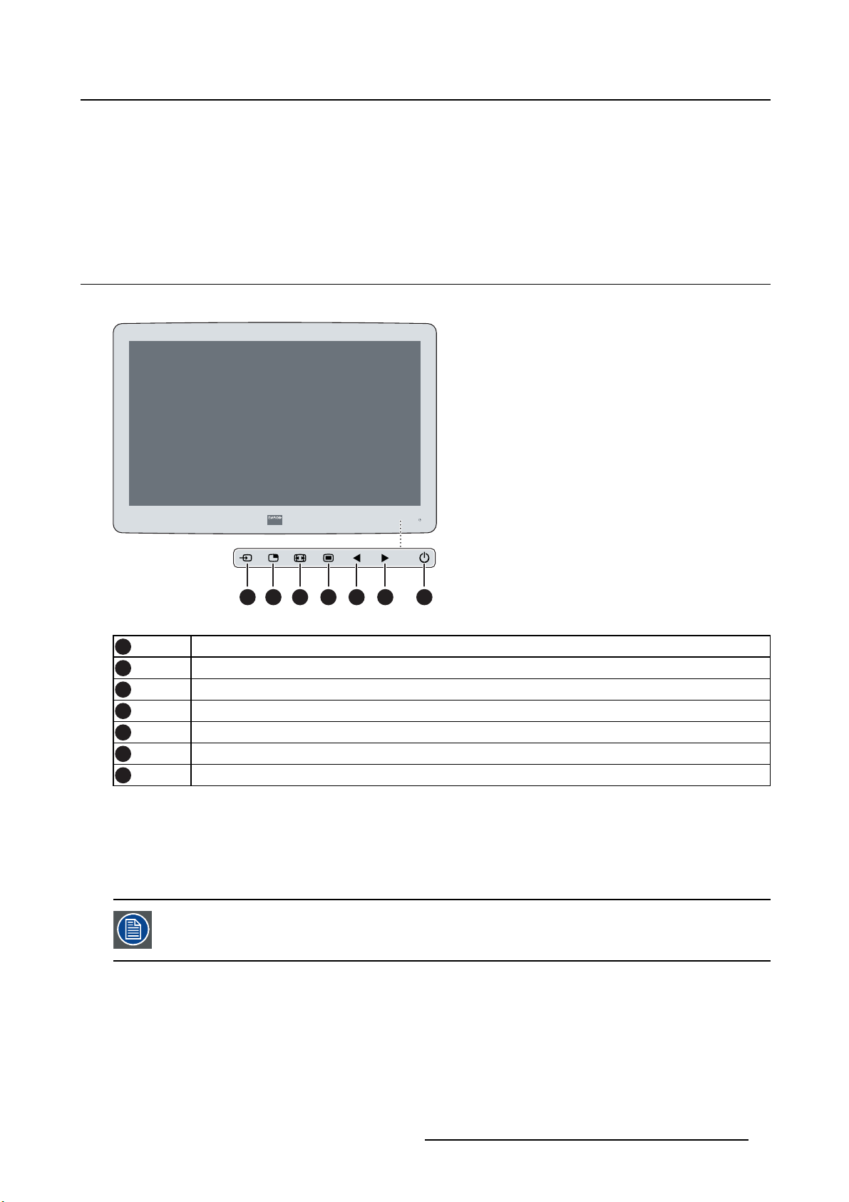
Image 2-1
1
2
3
4
5
6
7
A 7-key capacitive keypad is located on the front of the display. By default only the stand-by key is visible.
When you touch any of the keys shortly, the front illumination of all other keys is switched on for a few
seconds. When you touch any of these other keys again while the illumination is on, the function of the
key is executed. If no further action is taken within the time-out, the front key illumination is switched off
again.
Input Selection key
Multi-image selection key / Down key
Image zoom key / Up key
OSD Menu key / Enter key
Brightness decrease / Left key
Brightness increase / Right key
Stand-by key
The auto-dim function of the front key illumination can be disabled in the OSD menu.
(451920610993)K5903021 MDSC-2226 01/03/2013 5
Page 10
2. Parts, controls and connectors
2.2 Rear view
Overview
1
1 1
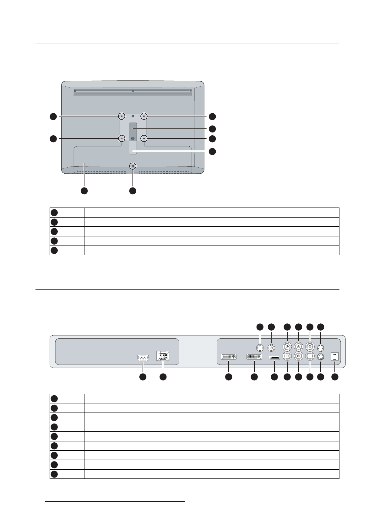
Image 2-2
1
2
3
4
5
4
VESA mount screw holes
Cable routing channel
Cable routing channel expansion clip
Connector compartment cover
Connector compartment cover fixation screw
5
2.3 Connector view
1
2
3
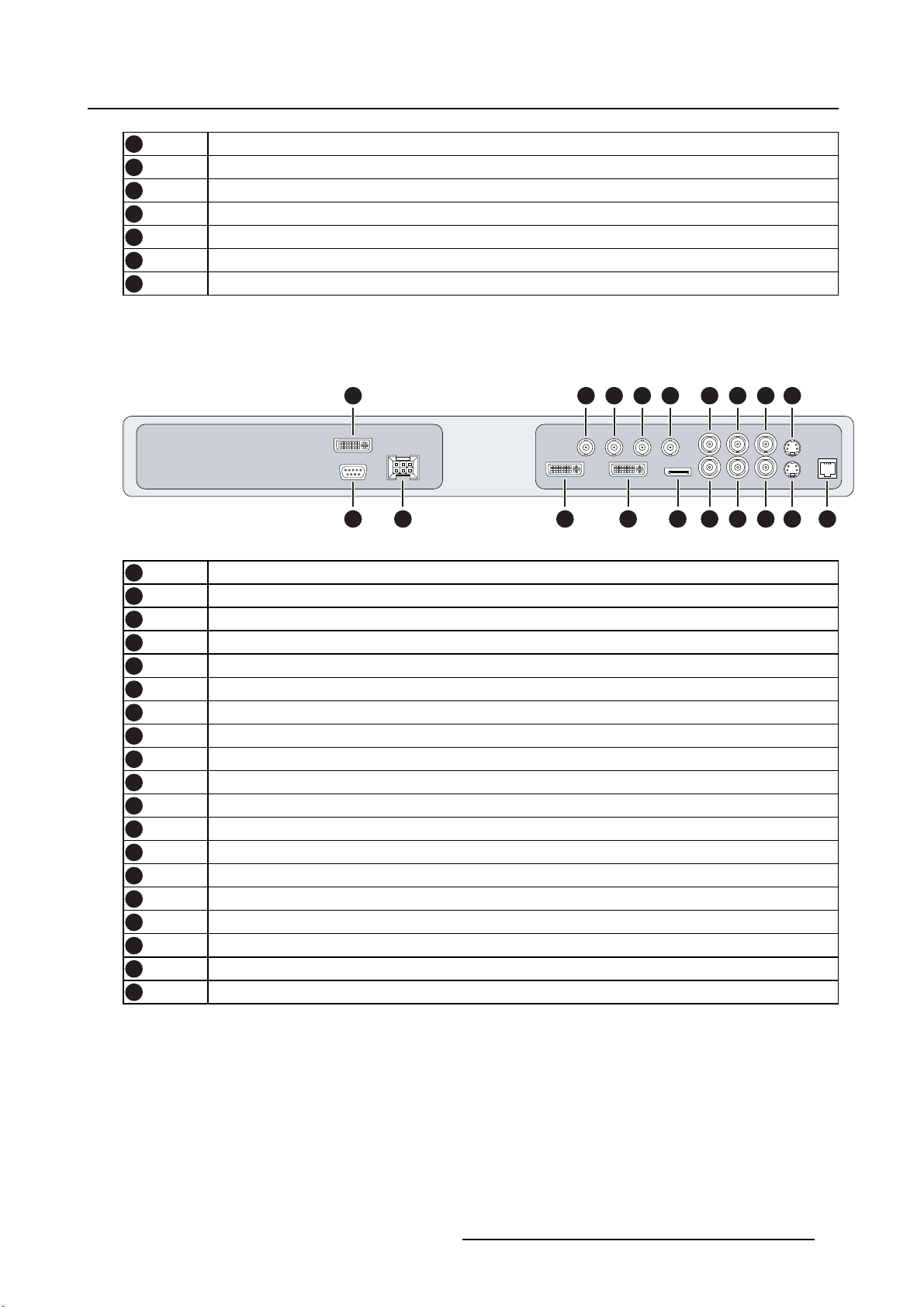
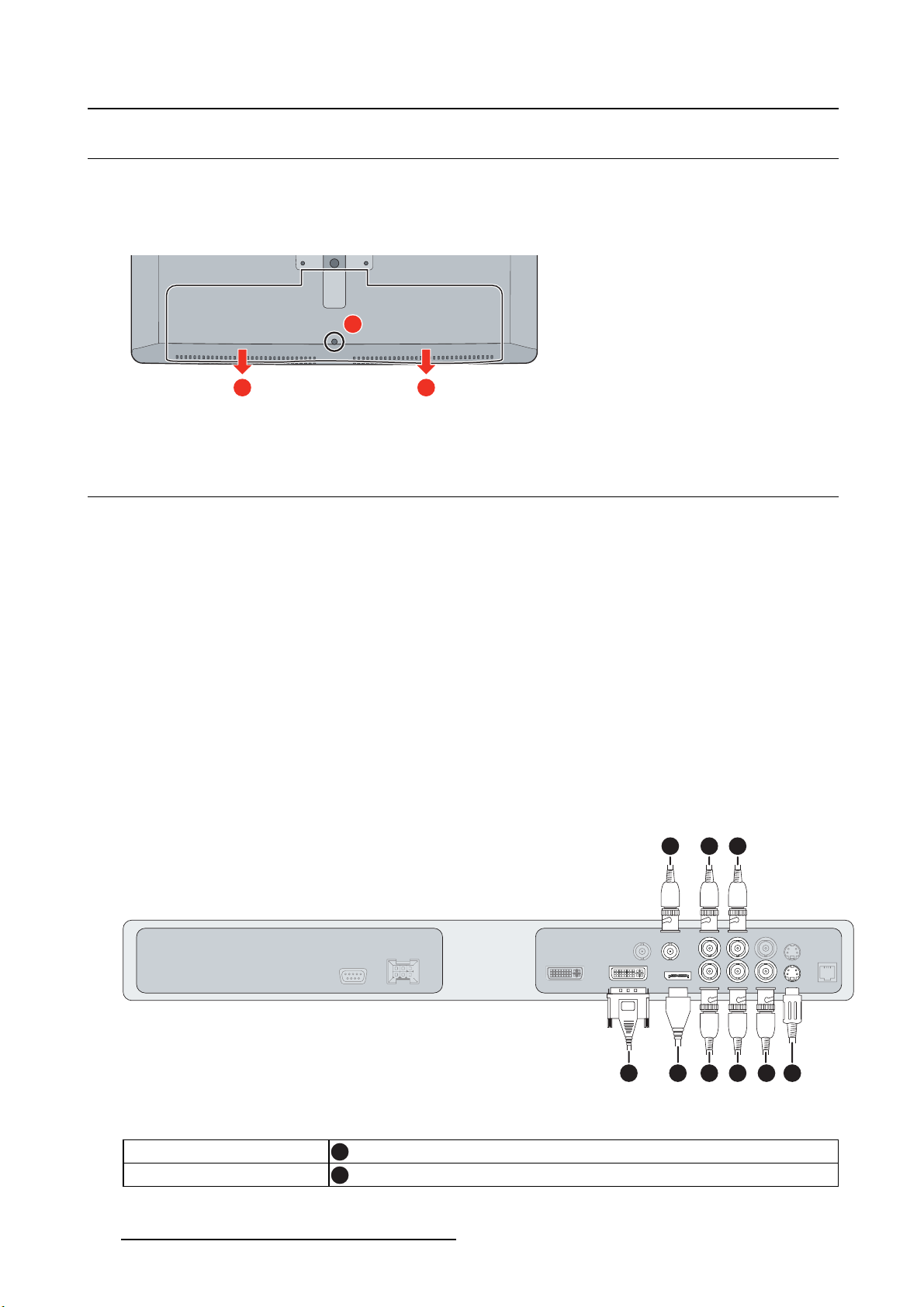
2.3.1 MDSC-2226 LED version
Overview
1 2 3 4 7 11 12 13 15
Image 2-3
1
2
3
4
5
6
7
8
9
RS232
Input power connector
DVI out
DVI-1 (digital & analog – HDMI video support with HDCP)
SDI-1 out
SDI-1
DisplayPort (VESA std 1.1a)
Sync
CVBS
865 9 10 14
16
6 (451920610993)K5903021 MDSC-2226 01/03/2013
Page 11
2. Parts, controls and connectors
10
11
12
13
14
15
16
CVBS out
R/Pr
G/Y
B/Pb
S-Video out
S-Video
Service
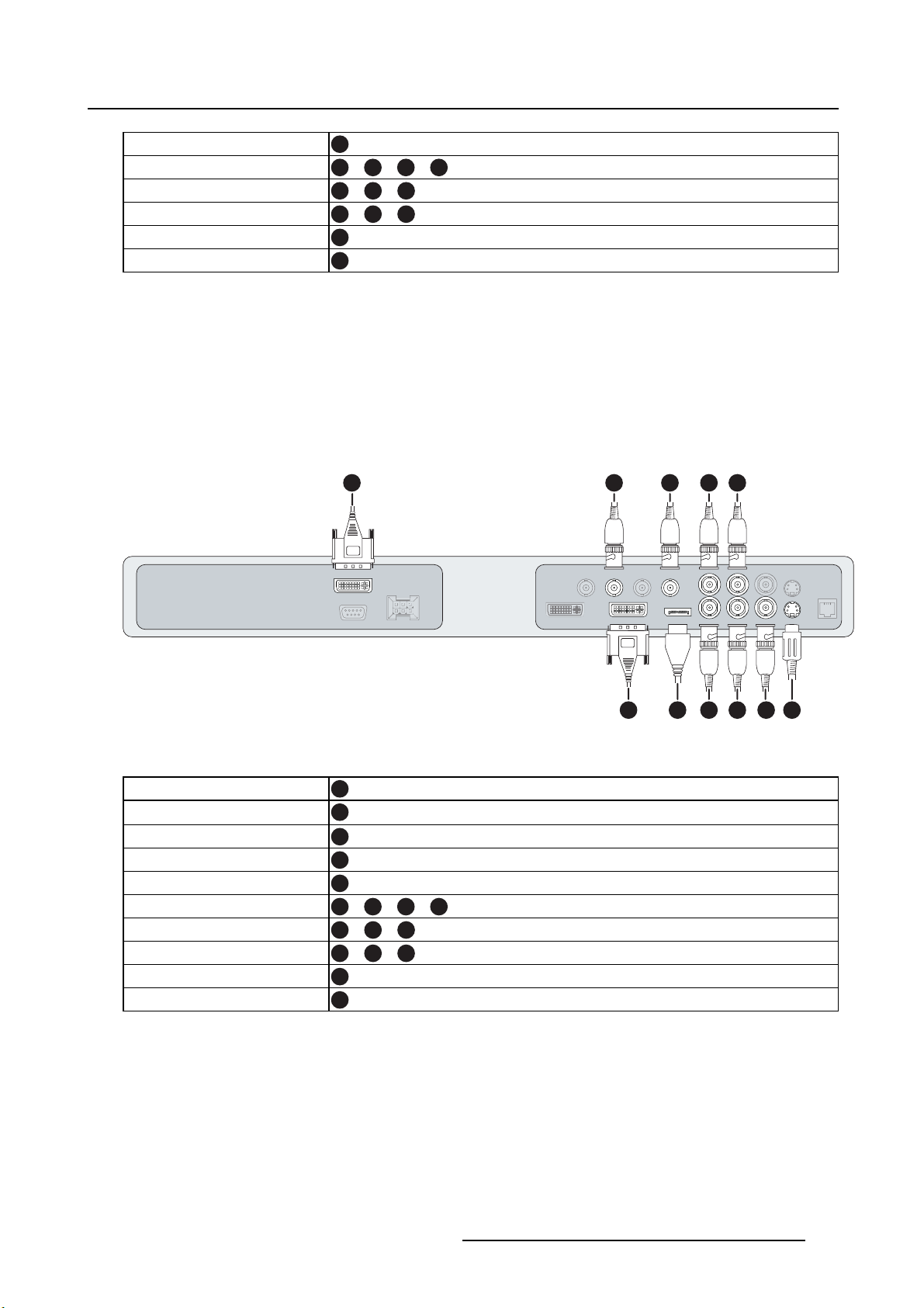
2.3.2 MDSC-2226 DDI version
Overview
2 3 4 5 10 14 15 16 18
Image 2-4
1
2
3
4
5
6
7
8
9
10
11
12
13
14
15
16
17
18
19
DVI-2
RS232
Input power connector
DVI out
DVI-1 (digital & analog – HDMI video support with HDCP)
SDI-2 out
SDI-2
SDI-1 out
SDI-1
DisplayPort (VESA std 1.1a)
Sync
CVBS
CVBS out
R/Pr
G/Y
B/Pb
S-Video out
S-Video
Service
1198761 12 13 17
19
(451920610993)K5903021 MDSC-2226 01/03/2013 7
Page 12
2. Parts, controls and connectors
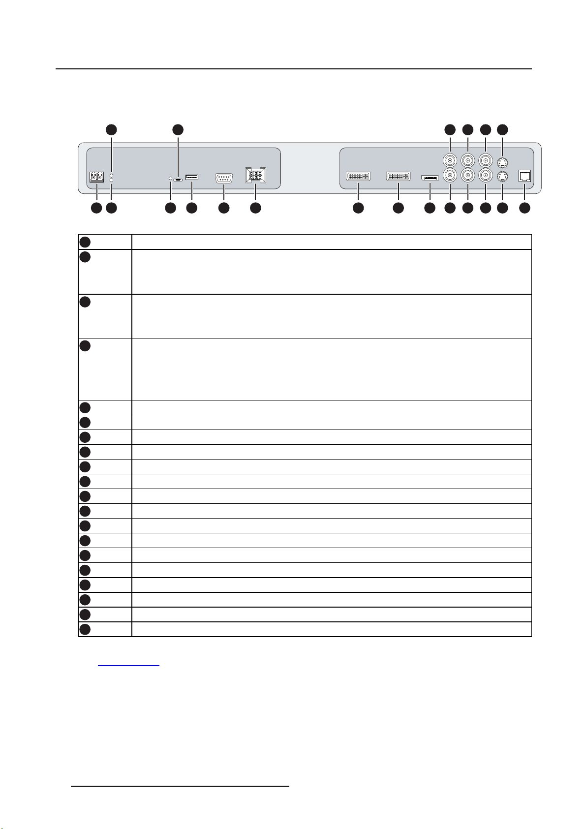
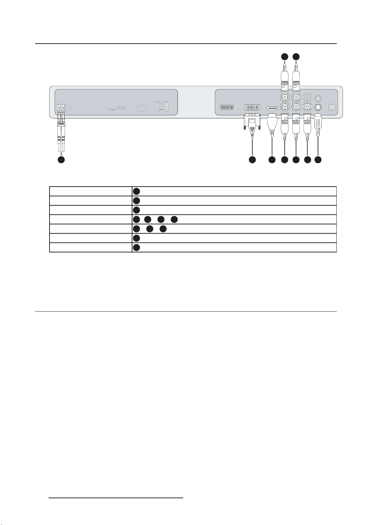
2.3.3 MDSC-2226 MNA version
Overview
3
125 13 14 18
1 2 4 6
Image 2-5
1
2
Optical 10Gb Ethernet SFP+ interface*
LED2*
Orange blinking: Activity = (Tx) or (Rx)
Off: No network activity
3
LED1*
Green: Link is active
Off: No active network connection
4
LED3*
Green: Power on, normal operation
Off: System not powered
Orange blinking: Error
5
6
7
8
9
10
11
12
13
14
15
16
17
18
19
20
Micro USB interface*
USB 2.0 type A interface*
RS232
Input power connector
DVI out
DVI-1 (digital & analog – HDMI video support with HDCP)
DisplayPort (VESA std 1.1a)
Sync
CVBS
CVBS out
R/Pr
G/Y
B/Pb
S-Video out
S-Video
Service
7
8 9 10 11 15 16 17 19
20
(*) Nexxis OR functionality: for more detailed information please refer to the dedicated user guides. Please
visit m
y.barco.com to obtain these user guides.
8
(451920610993)K5903021 MDSC-2226 01/03/2013
Page 13
2.4 Connector pin assignments
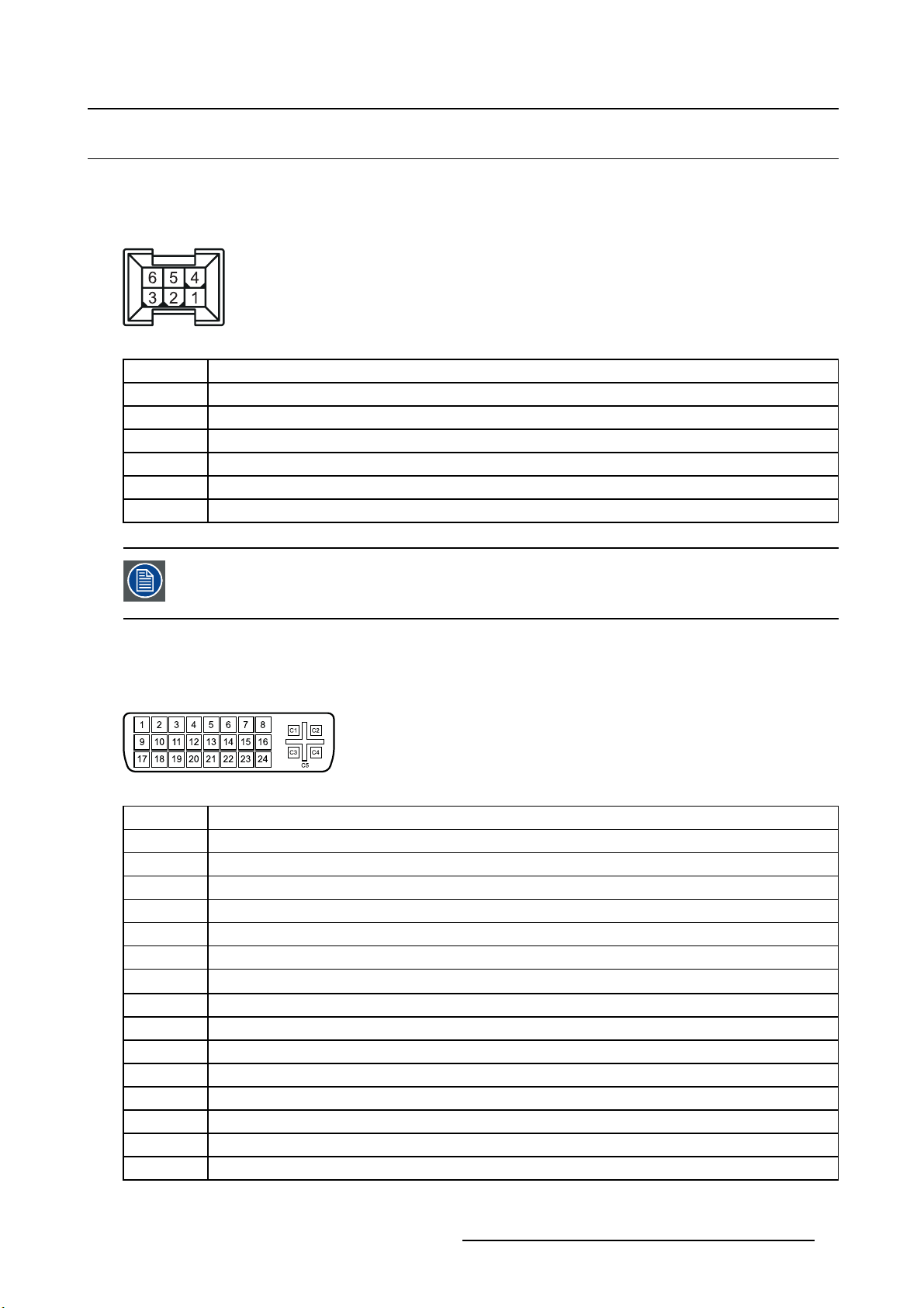
2.4.1 Input power connector
Overview
Image 2-6
Pin Function
1
2 Not connected
3
4
5
6
GND
+24 VDC
GND
Shield
+24 VDC
2. Parts, controls and connectors
The ground and the shield connections on the power input connector have no Protective
Earth function. A Protective Earth connection is prov ided via a dedicated pin (see image
3-10).
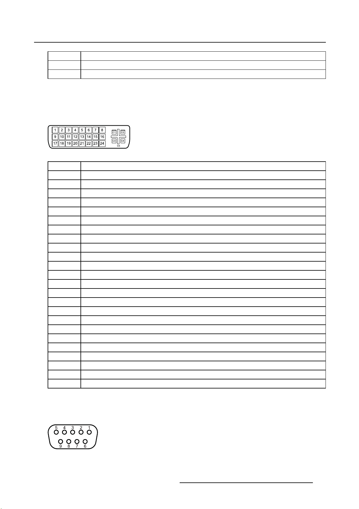
2.4.2 DVI–1 connector
Overview
Image 2-7
Pin Function
1 D2_Rx- (T.M.D.S.)
2 D2_Rx+ (T.M.D.S.)
3 GND (data 2 shield)
4 Not connected
5
6 SCL (for DDC)
7
8 Analog vertical sync
9
10
11
12 Not connected
13 Not connected
14
15
Not connected
SDA (for DDC)
D1_Rx- (T.M.D.S.)
D1_Rx+ (T.M.D.S.)
GND (data 1 shield)
+5V input (DDC supply) (*)
GND (cable sense)
(451920610993)K5903021 MDSC-2226 01/03/2013 9
Page 14
2. Parts, controls and connectors
16
17
18
19
20 Not connected
21 Not connected
22
23
24
C1
C2 Analog Green
C3
C4
C5 Analog GND return (analog R, G, B)
(*) +5 VDC output selectable on either pin 14 or 16 via the OSD menu.
Hotplugdetect(*)
D0_Rx- (T.M.D.S.)
D0_Rx+ (T.M.D.S.)
GND (data 0 shield)
GND (clock shield)
CK_Rx+ (T.M.D.S.)
CK_Rx- (T.M.D.S.)
Analog Red
Analog Blue
Analog horizontal sync
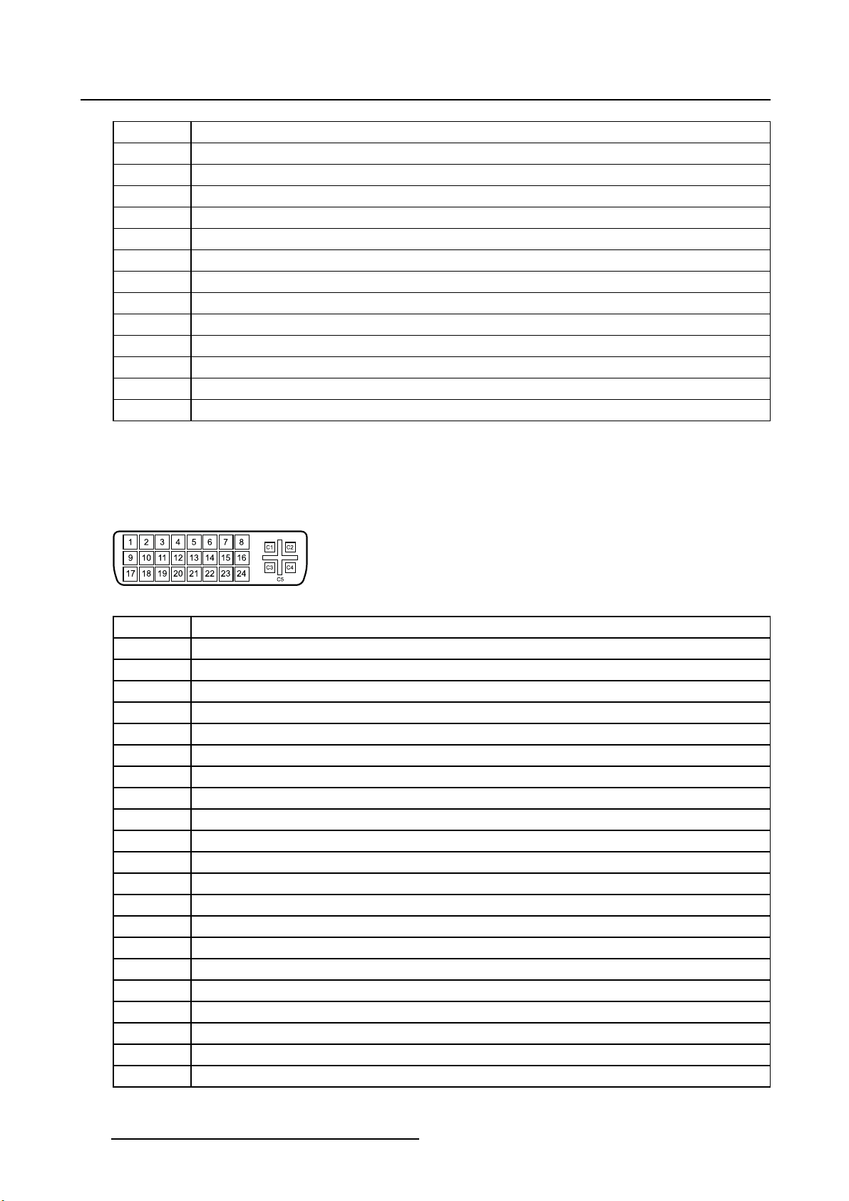
2.4.3 DVI-2 connector
Overview
Image 2-8
Pin Function
1
2
3
4 Not connected
5
6
7
8 Not connected
9
10
11
12 Not connected
13 Not connected
14
15
16
17
18
19
20 Not connected
21 Not connected
D2_Rx- (T.M.D.S.)
D2_Rx+ (T.M.D.S.)
GND (data 2 shield)
Not connected
SCL (for DDC)
SDA (for DDC)
D1_Rx- (T.M.D.S.)
D1_Rx+ (T.M.D.S.)
GND (data 1 shield)
+5V input (DDC supply) (*)
GND (cable sense)
Hotplugdetect(*)
D0_Rx- (T.M.D.S.)
D0_Rx+ (T.M.D.S.)
GND (data 0 shield)
10 (451920610993)K5903021 MDSC-2226 01/03/2013
Page 15
2. Parts, controls and connectors
22
23
24
(*) +5 VDC output selectable on either pin 14 or 16 via the OSD menu.
GND (clock shield)
CK_Rx+ (T.M.D.S.)
CK_Rx- (T.M.D.S.)
2.4.4 DVI out connector
Overview
Image 2-9
Pin Function
1
2
3
4 Not connected
5
6
7
8 Not connected
9
10
11
12 Not connected
13 Not connected
14 +5V output
15
16 Hot plug detect
17
18
19
20 Not connected
21 Not connected
22
23
24
D2_Rx- (T.M.D.S.)
D2_Rx+ (T.M.D.S.)
GND (data 2 shield)
Not connected
SCL (for DDC)
SDA (for DDC)
D1_Rx- (T.M.D.S.)
D1_Rx+ (T.M.D.S.)
GND (data 1 shield)
GND (cable sense)
D0_Rx- (T.M.D.S.)
D0_Rx+ (T.M.D.S.)
GND (data 0 shield)
GND (clock shield)
CK_Rx+ (T.M.D.S.)
CK_Rx- (T.M.D.S.)
2.4.5 RS232 connector
Overview
Image 2-10
(451920610993)K5903021 MDSC-2226 01/03/2013 11
Page 16
2. Parts, controls and connectors
Pin Function
1 Not connected
2
3
4 Not connected
5
6 Not connected
7
8 Not connected
9 Not connected
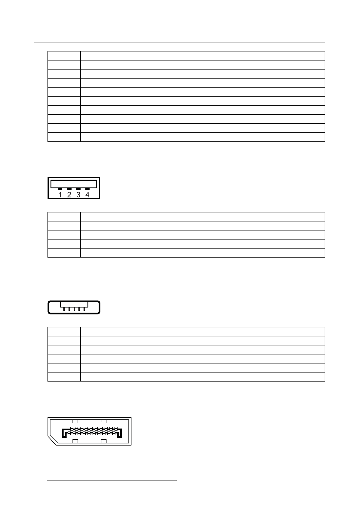
2.4.6 USB connector
Overview
Image 2-11
Rx (driven by host)
Tx (driven by display)
Ground
Not connected
Pin Function
1
+5 VDC
2Data—
3Data+
4
GND
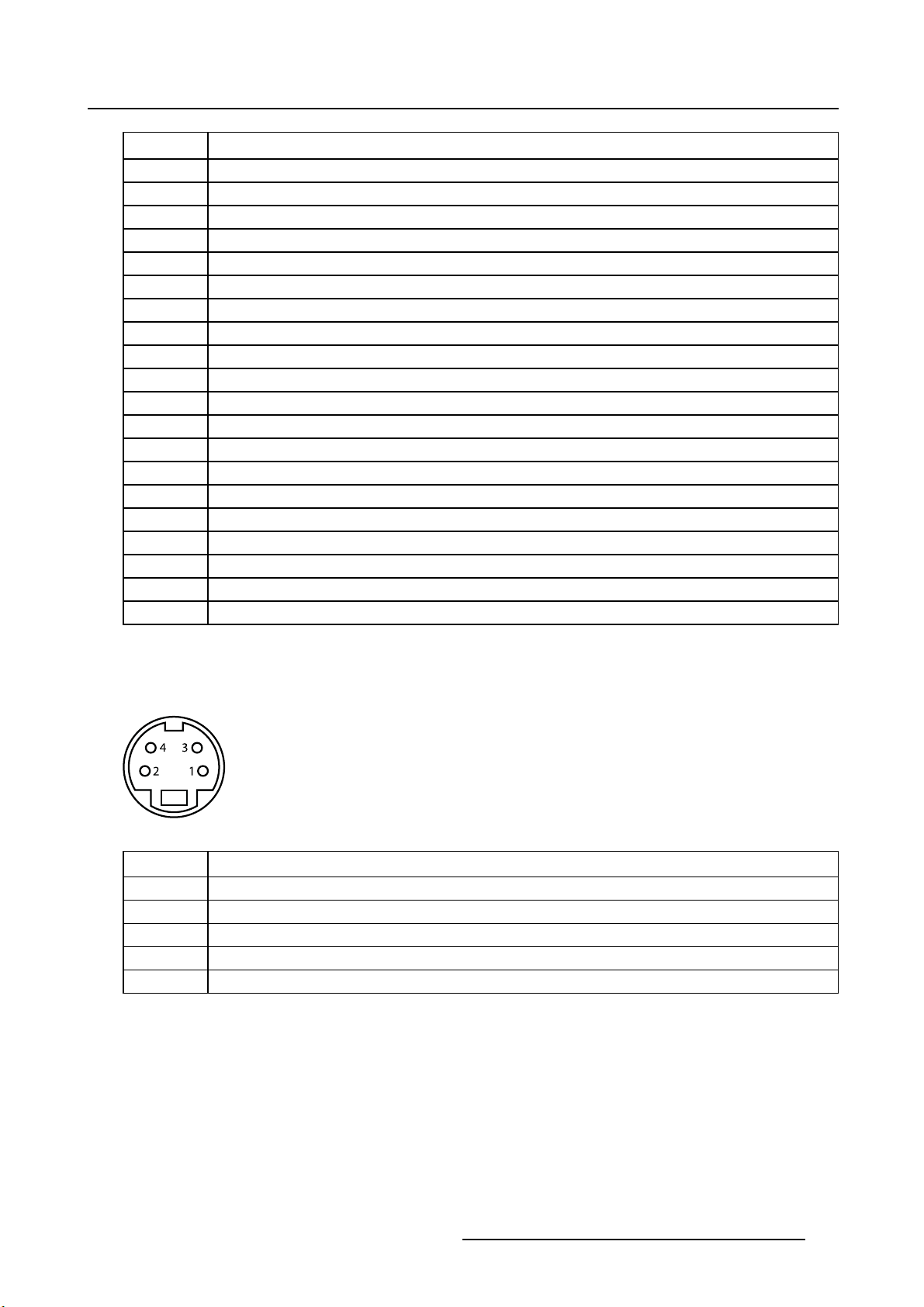
2.4.7 Mini USB connector
Overview
12345
Image 2-12
Pin Function
1+5VDC
2Data—
3Data+
X Not connected
4GND
2.4.8 DisplayPort connector
Overview
19 17 15 13 11 9 7 5 3 1
20 18 16 14 12 10 8 6 4 2
Image 2-13
12 (451920610993)K5903021 MDSC-2226 01/03/2013
Page 17
Pin Function
2. Parts, controls and connectors
1
2
3
4
5
6
7
8
9
10
11
12
13
14
15
16
17
18 Hot Plug
19 Return
20
ML_Lane 0 (p)
GND
ML_Lane 0 (n)
ML_Lane 1 (p)
GND
ML_Lane 1 (n)
ML_Lane 2 (p)
GND
ML_Lane 2 (n)
ML_Lane 3 (p)
GND
ML_Lane 3 (n)
CONFIG1
CONFIG2
AUX CH (p)
GND
AUX CH (n)
DP_PWR (+3.3 VDC)
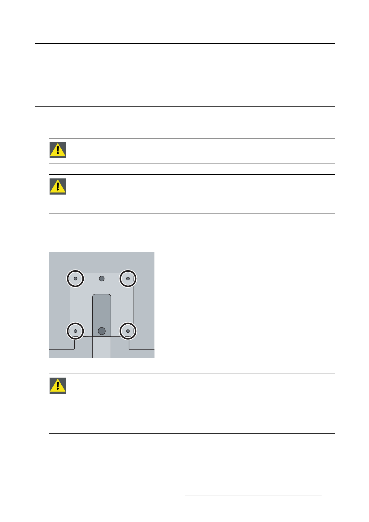
2.4.9 S-Video and S-Video-out connector
Overview
Image 2-14
Pin Function
1
2
3
4
SG Shielded Ground
Ground (Y)
Ground (C)
Luminance (Y)
Chroma (C)
(451920610993)K5903021 MDSC-2226 01/03/2013 13
Page 18

2. Parts, controls and connectors
14 (451920610993)K5903021 MDSC-2226 01/03/2013
Page 19
3. DISPLAY INSTALLATION
3.1 VESA mount installation
Overview
The display supports arm stands according to the VESA 100 mm standard.
CAUTION: Use an arm that is approved by VESA.
CAUTION: Use an arm that can support a weight of least 10 kg (22,05 lbs).
The monitor VESA interface has been designed for a safety fa ctor 6 (to support 6 times
the monitor weight). In the medical system, use an arm with suitable safety factor
(IEC60601–1).
3. Display installation
To mount the display to an arm stand
1. Attach the arm stand firmly to the panel using the included 4 hexagonal screws (M4 x 25 mm) and the
dented washers. Use the included Allen key to fixthescrews.
Image 3-1
CAUTION: The4screwsincludedwiththisdisplay(M4x25mm)canbeusedforan
external VESA arm interface with a thickness of up to 5mm.
If, due to the thickness of the extern
screws (=L) is not suitable, consider the following rule:
al VESA arm interface (=V), the length of the provided
L
=V+20mm
min
=V+30mm
L
max
(451920610993)K5903021 MDSC-2226 01/03/2013 15
Page 20
3. Display installation
3.2 Cover removal
To remove the connector compartment cover
1. Loosen the screw fixing the connector compartment cover.
2. Slide the cover downwards to remove it from the display.
1
2 2
Image 3-2
3.3 Video input connection
About video input connections
The MDSC-2226 can have multiple different video inputs connected (depending on the display version).
Switching between the different inputs can be easily done by pressing the direct access key for this. See
the dedicated section for more info.
Futhermore, if more than one video source is connected, the Picture in Picture (PiP) and Side-by-Side
(SbS) functionality becomes available, allowing you to view two different video inputs at once. Please
refer to the dedicated chapter for more info on how to activate and use the PiP and SbS features on your
MDSC-2226.
This chapter describes how to connect the different video input types for each version of the MDSC-2226.
3.3.1 MDSC-2226 LED version
To connect the video inputs
1. Connect one or more of the available video source(s) to the corresponding video inputs using the ap-
propriate video cable(s).
1
2 3
4 5 6 7 8
Image 3-3
DVI or VGA (*)
DisplayPort
16 (451920610993)K5903021 MDSC-2226 01/03/2013
4
5
9
Page 21
3. Display installation
SDI
R/G/B/S
R/G/B (SOG)
Y/Pb/Pr
CVBS
S-Video
1
6/7/8/2
6/7/8
7/8/6
3
9
(*) PC analog (VGA) input source can be connected to the DVI-I input connector using a DVI-I to VGA
adapter. The use of an adapter cable of at least 0.15 m long will allow an easy placement inside the cable
cover.
3.3.2 MDSC-2226 DDI version
To connect the video inputs
1. Connect one or more of the available video source(s) to the corresponding video inputs using the ap-
propriate video cable(s).
2
31 4 5
6 7 8 9 10
Image 3-4
DVI 1 or VGA (*)
DVI 2
DisplayPort
SDI 1
SDI 2
R/G/B/S
R/G/B (SOG)
Y/Pb/Pr
CVBS
S-Video
6
1
7
3
2
8/9/10/4
8/9/10
9/10/8
5
11
(*) PC analog (VGA) input source can be connected to the DVI-I input connector using a DVI-I to VGA
adapter. The use of an adapter cable of at least 0.15 m long will allow an easy placement inside the cable
cover.
3.3.3 MDSC-2226 MNA version
To connect the video inputs
11
1. Connect one or more of the available video source(s) to the corresponding video inputs using the ap-
propriate video cable(s).
(451920610993)K5903021 MDSC-2226 01/03/2013
17
Page 22
3. Display installation
1 2
4 5 6 7 8
Image 3-5
Nexxis
DVI or VGA (*)
DisplayPort
R/G/B/S
Y/Pb/Pr
CVBS
S-Video
(*) PC analog (VGA) input source can be connected to the DVI
3
4
5
6/7/8/1
7/8/6
2
9
-I input connector using a DVI-I to VGA
adapter. The use of an adapter cable of at least 0.15 m long will allow an easy placement inside the cable
cover.
3.4 Video output c on nection
About video output connections
Beside the video input connections, the MDSC-2226 also has video output capabilities allowing you to
loop-through certain video inputs connected with the MDSC-2226 to another display, projector, video
recorder, ...
93
This chapter describes how to make use of the video output connections available for each version of the
MDSC-2226.
3.4.1 MDSC-2226 LED version
To connect the video outputs
1. Connect one or more of the available video sink(s) to the corresponding video outputs using the appro-
priate video cable(s).
18
(451920610993)K5903021 MDSC-2226 01/03/2013
Page 23

3. Display installation
Image 3-6
SDI
CVBS
S-Video
DVI
1
2
3
4
(tobeconfiguredinOSDmenu)
3.4.2 MDSC-2226 DDI version
1
4
2 3
To connect the video outputs
1. Connect one or more of the available video sink(s) to the corresponding video outputs using the appro-
priate video cable(s).
2 3 41
5
Image 3-7
SDI 1
SDI 2
CVBS
S-Video
DVI 1 or DVI 2
2
1
3
4
5
(tobeconfiguredinOSDmenu)
(451920610993)K5903021 MDSC-2226 01/03/2013 19
Page 24

3. Display installation
3.4.3 MDSC-2226 MNA version
To connect the video outputs
1. Connect one or more of the available video sink(s) to the corresponding video outputs using the appro-
priate video cable(s).
3
Image 3-8
1 2
CVBS
S-Video
DVI
Nexxis
1
2
3
(tobeconfiguredinOSDmenu)
3
(tobeconfiguredinOSDmenu)
3.5 Nexxis OR
Overview
Connecting your MDSC-2226 to Barco’s Nexxis OR system allows you to distribute video, graphics, audio
and computer data over the IP network, in raw uncompressed format, inside the operating room and even
between surgical suites.
To connect your MDSC-2226 to Barco’s Nexxis OR system, connect the 10Gb Ethernet interface to your
Nexxis switch. More info about Nexxis OR and how to configure the MDSC-2226 in your network is available in the dedicated user guides. Please visit m
Nexxis OR is only available on the MDSC-2226 MNA version.
y.barco.com to obtain these user guides.
3.6 Power supply connection
To connect the power supply
1. Connect the supplied external DC power supply unit to the +24 VDC power input of your MDSC-2226
display.
20
(451920610993)K5903021 MDSC-2226 01/03/2013
Page 25

3. Display installation
2. Plug the other end of the external DC power supply into a grounded power outlet by means of the
proper power cord delivered in the packaging.
Note: The ground and the shield connections on the power input connector have no Protective Earth
function. A Protective Earth connection is provided via a dedicated pin (see image 3-10).
Image 3-9
Protective earth pin
1. Earth the MDSC-2226 by connecting the protective earth pin to a grounded outlet by means of an
AWG18 (max. 6ft / 1,8m long) wire.
1
Image 3-10
3.7 Cable routing
To route the cables
1. For displays mounted to a VESA arm with internal cable routing provisions, route all cables through the
cable routing channel, then reinstall the connector compartment cover.
8a
Image 3-11
(451920610993)K5903021 MDSC-2226 01/03/2013 21
Page 26

3. Display installation
Or,
For all other mounting options, remove the cable routing channel expansion clip from the connector
compartment cover and route all cables through it while reinstalling the cover.
8b
Image 3-12
WARNING: When the display is assembled in the medical system, take care of the an-
chorage of all cables, to avoid unwanted detachment.
22 (451920610993)K5903021 MDSC-2226 01/03/2013
Page 27

4. Daily operation
4. DAILY OPERATION
4.1 Keyboard backlight
About the keyboard backlight
By default only the stand-by key is visible. When you touch any of the keys shortly, the backlight of all
other keys is switched on for a few seconds. When you touch any of these keys again while the backlight
is on, the function of the key is executed. If no further action is taken within the time-out, the keyboard
backlight is switched off again.
The keyboard backlight auto-dim function can be disabled in the OSD menu so that the
keyboard backlight is always on (Keyboard Backlight).
4.2 On/Off switching
To switch on your display:
1. Activate the power supply through the switch located on the external power supply.
2. While your display is off, press and hold the stand-by key
To minimize the power consumption, also the external power supply has to be switched
off.
for approximately 3 seconds.
To switch off your display:
1. While your display is switched on, press and hold the stand-by key for approximately 3 seconds.
While pressing the stand-by key to switch off the display, the front key illumination will
blink.
4.3 OSD menu activation
To activate the OSD menu
1. If not already done so, switch on the display by pressing and holding the stand-by key for approxi-
mately 3 seconds.
2. Switch on the front key illumination.
3. Touch the Menu/Enter key
As a result, the OSD main menu comes up in the bottom right corner of the screen. If no further actions
are taken within the following 30 seconds, the OSD menu will disappear again.
(451920610993)K5903021 MDSC-2226 01/03/2013
.
23
Page 28

4. Daily operation
The time-out of the OSD menu automatic close function can be adjusted or disabled in
the OSD menu (OSD Time-out).
The OSD menu position can be adjusted in the OSD menu (OSD Hor. Pos. and OSD Vert.
Pos.).
4.4 OSD menu navigation
OSD menu structure explained
Below is on example of how the OSD menu structure looks like:
4
Picture
Profile Factory
Brightness 50
Contrast 50
1
Saturation 30
Color temperature 6500K
Gamma Native
Sharpness 10
5
DVI 1280x800@60Hz
32
Image 4-1
1
2
3
4
5
Menu
Sub-menu
Status bar
Selector/Slider
Item
To navigate through the OSD menu
Image 4-2
24 (451920610993)K5903021 MDSC-2226 01/03/2013
Page 29

4. Daily operation
•Pressthekey to open the OSD menu.
•Usethe
• When the desired Menu page is highlighted, press the
or key to scroll to the desired menu page.
key to select the top menu item that will be
highlighted.
•Usethe
• If the selected menu item is controlled by a slider use the
press the
• If the selected menu item is a multiple choices menu use the
then press the
• Press again
or keys to move to other Menu Items, then press the key to select it.
or keys to adjust the item value, then
key to confirm.
or keys to select the desired option
key to confirm.
or key to select other Menu items or exit from the Menu page by pressing the key.
4.5 Shortkey functio ns
About shortkey functions
The concept of shortkey functions is to present a selection of commonly used functions immediately available without the need to navigate through the OSD Menu.
The different available shortkey functions are:
• Main source selection
•Multi-imageconfiguration
• Zoom factor selection
• Brightness adjustment
Unlike the extended keyboard functions (described in next chapter), the shortkey functionality is immediately av aila ble without the need to first enable this in the OSD menu.
When the extended keyboard functionality is enabled, all the shortkey f
scribed below (ex cept for the brightness adjustment), will no longer be available and
will be replaced by the corresponding extended keyboard functions described in the
next chapter.
Overview of shortkeys
1
2
3 4 5
Image 4-3
1
2
3
4
5
Main source selection
Multi-image configuration
Zoom factor selection
Brightness decrease
Brightness increase
unctions de-
(451920610993)K5903021 MDSC-2226 01/03/2013 25
Page 30

4. Daily operation
4.5.1 Main source selection
To quickly select the main source
1. Use the Input selection key ( ) to scroll through all the possible input signals to select the main input
source.
Available main source options dependent on display model.
When the ex tended keyboard functionality is enabled, this shortkey functions will no
longer be available and will be replaced by the corresponding extended keyboard functions described in the next chapter.
4.5.2 Multi-image configuration
To quickly select the multi-image configuration
1. Use the PiP selection key ( ) to scroll through all possible configurations of Picture-in-Picture (PiP) and
Side-by-Side (SbS).
The different PiP/SbS options are:
- Small PiP: 30% of Primary height in top-right corner
- Large PiP: 50% of Primary height in top-right corner
- Side-by-Side: Primary and Secondary input of equal height
Only a subset of multi-image configuration settings is available via this shortkey function. More multi-image configuration settings can be selected in the OSD menus.
When the ex tended keyboard functionality is enabled, this shortkey functions will no
longer be available and will be replaced by the corresponding extended keyboard functions described in the next chapter.
4.5.3 Zoom factor selection
To quickly select the zoom factor
1. Use the Image zoom key ( ) to select one of the available zoom factors.
When the ex tended keyboard functionality is enabled, this shortkey functions will no
longer be available and will be replaced by the corresponding extended keyboard functions described in the next chapter.
4.5.4 Brightness adjustment
To quickly adjust the brightness
1. While no OSD Menu is on the screen, press the Brightness decrease ( ) or Brightness increase ( )
keys to adjust the brightness as desired.
26
(451920610993)K5903021 MDSC-2226 01/03/2013
Page 31

4. Daily operation
Brightness
50
Image 4-4
When the extended keyboard functionality is enabled, this shortkey functions will remain available.
4.6 Extended keyboard functions
About extended keyboard functions
The concept of the extended keyboard is to present a large selection of functions immediately available
to the user without the need to navigate through the OSD Menu.
Once enabled, by simply pressing one of the first 3 keys on the left the user is presented with a list of new
selections displayed on screen; the new choices can be selected by using each of the key just below the
OSD text.
If two options are available for one key, the first key press will select the upper option, a second press
selects the lower option.
The different available extended keyboard functions are:
• Main source selection
• Second source selection
•Multi-imageconfiguration
• Color temperature selection
• Image size selection
• Zoom factor selection
Unlike the shortkey functions (described before), the extended keyboard functionality
must be first enabled in the OSD menu before you can make use of it. Please refer to the
dedicated section in this manual for more details on how to enable/disable the extended
keyboard functions.
When the extended keyboard functionality is enabled, all the shortkey functions described in previous chapter (except for the brightness adjustment), will no longer be
available and will be replaced by the corresponding extended keyboard functions described below.
Overview of extended keyboard
1
2
3
Image 4-5
(451920610993)K5903021 MDSC-2226 01/03/2013 27
Page 32

4. Daily operation
1
Main source selection
Second source selection
2
3
Multi-image configuration
Color temperature selection
Image size selection
Zoom factor selection
4.6.1 Main source selection
To quickly select the main source
1. While no OSD Menu is on the screen, press the Input selection key ( ) to bring up the main source
quick selection menu.
2. Toggle the available main source options by pressing the key corresponding to the desired option.
If two options are available for one key, the first key press will select the upper option, a second press
selects the lower option.
Thecurrentselectionismarkedinred.
3. Press the stand-by key (
Main source
VGADPR G B
Y Pb Pr
S-Video
CVBS
DVI
SDI Nexxis 2nd Source
)toconfirm your choice and exit the main source quic
E
X
I
T
k selection menu.
Image 4-6
Note: Available main source options dependent on display model.
4.6.2 Second source selection
To quickly select the second source
1. While no OSD Menu is on the screen, press the Input selection key ( ) to bring up the second source
quick selection menu.
2. Press the
3. Toggle the available second source options by pressing the key corresponding to the desired option.
If two options are available for one key, the first key press will select the upper option, a second press
selects the lower option.
Thecurrentselectionismarkedinred.
4. Press the stand-by key (
2nd Source
VGADPR G B
keytoswitchtothe2ndsourcequickselectionmenu.
)toconfirm your choice and exit the second source quick selection menu.
E
X
I
T
Y Pb Pr
S-Video
CVBS
DVI
SDI Nexxis Main source
28
Image 4-7
Note: Available second source options dependent on display model.
(451920610993)K5903021 MDSC-2226 01/03/2013
Page 33

4. Daily operation
4.6.3 Multi-image configuration
To quickly select the multi-image configuration
1. While no OSD Menu is on the screen, press the PiP selection key ( ) to bring up the multi-image
configuration quick selection menu.
2. Toggle the available multi-image configurations by pressing the key corresponding to the desired option.
Thecurrentselectionismarkedinred.
3. Press the stand-by key (
)toconfirm your choice and exit the multi-image configuration quick selection
menu.
Multi image config.
Native Aspect Fill Small Large None
E
X
I
T
Image 4-8
4.6.4 Transfer function selection
To quickly select the transfer function
1. While no OSD Menu is on the screen, press the Image zoom key ( ) to bring up the common functions
quick selection menu.
2. Toggle the available transfer function settings by pressing the key corresponding to the desired option.
Thecurrentselectionismarkedinred.
3. Press the stand-by key (
Common Functions
ITU 709 6500°K DICOM Native Aspect Zoom
)toconfirm your choice and exit the common functions quick selection menu.
E
X
10%
I
T
Image 4-9
Note: Only a subset of transfer function settings is available via this quick selection menu. More transfer
function settings can be selected in the OSD menus.
4.6.5 Image size selection
To quickly select the image size
1. While no OSD Menu is on the screen, press the Image zoom key ( ) to bring up the common functions
quick selection menu.
2. Toggle the available image size settings by pressing the key corresponding to the desired option.
Thecurrentselectionismarkedinred.
3. Press the stand-by key (
(451920610993)K5903021 MDSC-2226 01/03/2013
)toconfirm your choice and exit the common functions quick selection menu.
29
Page 34

4. Daily operation
Common Functions
ITU 709 6500°K DICOM Native Aspect Zoom
Image 4-10
10%
E
X
I
T
Note: Only a subset of image size settings is available via this quick selection menu. More image size
settings can be selected in the OSD menus.
4.6.6 Zoom factor selection
To quickly select the zoom factor
1. While no OSD Menu is on the screen, press the Image zoom key ( ) to bring up the common functions
quick selection menu.
2. Toggle the available zoom factors by repeatedly pressing the
shown.
3. Press the stand-by key (
Common Functions
ITU 709 6500°K DICOM Native Aspect Zoom
)toconfirm your choice and exit the common functions quick selection menu.
E
X
10%
I
T
key until the desired zoom factor is
Image 4-11
4.7 Keyboard locking/unlocking
To lock/unlock the keyboard
The keyboard can be locked from the Menu to avoid unwanted access to OSD functions. When the keyboard is LOCKED only the OSD Menu key (
keyispressedtheKeyboard Locked window appears.
1. To unlock the keyboard the following sequence of keys need to be pressed:
, , ,
Each time a key is pressed an asterisk is shown in the square boxes.
After pressing the fourth key, if the se
keyboard permanently the specific OSD function is required.
) and the Stand-by key ( ) are active. When the Menu OSD
quence is correct, the main OSD menu is activated. To unlock the
30
(451920610993)K5903021 MDSC-2226 01/03/2013
Page 35

Sequence: 5 - 6 - 6 - 3
Image 4-12
4. Daily operation
Keyboard lock
(451920610993)K5903021 MDSC-2226 01/03/2013 31
Page 36

4. Daily operation
32 (451920610993)K5903021 MDSC-2226 01/03/2013
Page 37

5. ADVANCED OPERATION
5.1 OSD pictu re menu
Overview
•Profile
• Brightness
• Contrast
• Saturation
• Color temperature
•Gamma
• Sharpness
5.1.1 Profile
About profiles
5. Advanced operation
To select a profile means to load a set of predefined video parameters like Brightness
tion, Input selection (Primary & Secondary), Multi-image layout selection, etc.
The user can modify the default video parameters associated to each profile and save the new parameters
setting under the User 1, User 2 or User 3 profile. The Factory and X Ray profiles can be temporary
modified, but the factory default can’t be overwritten and can always be recalled through the recall profile
menu item.
The available profiles for your display are:
•Factory
•XRay
•User1
•User2
•User3
, Contrast, Satura-
To se lec t a pro file
1. Bring up the OSD main menu.
2. Navigate to the Picture menu.
3. Enter the Profile submenu.
4. Select one of the available profiles and confirm.
5.1.2 Brightness
To adjust the brightness level
1. Bring up the OSD main menu.
2. Navigate to the Picture menu.
3. Enter the Brightness submenu.
The command bar Brightness is highlighted.
4. Set the brightness level as desired and confirm.
(451920610993)K5903021 MDSC-2226 01/03/2013
33
Page 38

5. Advanced operation
The selected brightness is maintained at a constant level by the automatic backlight
stabilization function.
The brightness level can also be adjusted through a shortkey function.
5.1.3 Contrast
To adjust the contrast level
1. Bring up the OSD main menu.
2. Navigate to the Picture menu.
3. Enter the Contrast submenu.
The command bar Contrast is highlighted.
4. Set the contrast level as desired and confirm.
5.1.4 Saturation
To adjust the saturation level
1. Bring up the OSD main menu.
2. Navigate to the Picture menu.
3. Enter the Saturation submenu.
The command bar Saturation is highlighted.
4. Set the saturation level as desired and confirm.
5.1.5 Color temperature
About color temperature presets
The available color temperature presets for your display are:
• 5600K
• 6500K
• 7600K
• 9300K
• ITU 709
•Native
•User
Factory calibration – White point:
The White Color points associated with the Color Temperature: 5600K, 6500K, 7600K or
9300K are factory calibrated with a consequent reduction of the maximum luminance
compared to Native Color Temperature.
34 (451920610993)K5903021 MDSC-2226 01/03/2013
Page 39

5. Advanced operation
Factory calibration – Color space:
When ITU 709 is selected, the White Color point and the RGB color primaries are adjusted according to the target HDTV / sRGB color space defined in the ITU-709 recommendation. RGB primary calibration is performed within the physical limitation of the
LCD panel used.
Only in case the User preset has been selected it is possible to get access to the color
regulation commands described hereafter.
To select a color temperature preset
1. Bring up the OSD main menu.
2. Navigate to the Picture menu.
3. Enter the Color Temperature submenu.
4. Select one of the available color temperature presets and confirm.
Note: If you selected the User color temperature preset, a new menu will be displayed allowing you to
manually adjust the gain and offset of red, green and blue.
5.1.6 Gamma
About gamma presets
The available gamma presets for your display are:
• CRT (Gamma 2.2)
• Native (no correction curve is applied)
• DICOM (grayscale levels are following closely the DICOM curve)
Factory calibration – Grayscale tracking:
When Gamma is set to “CRT” or Color Temperature preset is set to “ITU 709” mode, a
Grayscale Color Tracking is implemented according to the factory calibration on different gray level.
To select a gamma preset
1. Bring up the OSD main menu.
2. Navigate to the Picture menu.
3. Enter the Gamma submenu.
4. Select one of the available gamma presets and confirm.
5.1.7 Sharpness
To adjust the sharpness level
1. Bring up the OSD main menu.
2. Navigate to the Picture menu.
3. Enter the Sharpness submenu.
The command bar Sharpness is highlighted.
4. Set the sharpness level as desired and confirm.
(451920610993)K5903021 MDSC-2226 01/03/2013
35
Page 40

5. Advanced operation
5.2 Picture Advanced menu
Overview
•BlackLevel
•SmartVideo
•ImagePosition
• Auto Adjustment
•Phase
•Clock/Line
5.2.1 Black Level
To adjust the black level
1. Bring up the OSD main menu.
2. Navigate to the Picture advanced menu.
3. Enter the Black Level submenu.
The command bar Black Level is highlighted.
4. Set the black level as desired and confirm.
5.2.2 Smart Video
About Smart Video
To select a Smart Video preset means to select the processing speed of video signals.
The available Smart Video presets for your display are:
• Diagnostic (best picture quality)
• Surgical (low latency)
• Surgical 1 (low latency, optimized for fast moving images)
To select a Smart Video preset
1. Bring up the OSD main menu.
2. Navigate to the Picture advanced menu.
3. Enter the Smart Video submenu.
4. Select one of the available Smart Video presets and confirm.
5.2.3 Image Position
To adjust the image position
1. Bring up the OSD main menu.
2. Navigate to the Picture advanced menu.
3. Enter the Image Position submenu.
A small OSD menu will be activated indicating the horizontal and vertical image position offset.
4. Use the
5. Use the
6. When finished, use the
36
and keys to move the picture up and down.
and keys to move the picture left and right.
key to exit from the small OSD menu.
(451920610993)K5903021 MDSC-2226 01/03/2013
Page 41

5. Advanced operation
5.2.4 Auto Adjustment
This menu item is only available when VGA input is connected.
About auto adjustment
When auto adjustment is activated, the phase and clock per line parameters are automatically adjusted.
To activate auto adjustment
1. Bring up the OSD main menu.
2. Navigate to the Picture advanced menu.
3. Enter the Auto Adjustment submenu.
The automatic picture adjustment is activated: the phase and clock per line parameters are automatically adjusted.
5.2.5 Phase
About phase
If the result of the Auto Adjustment procedure described above isn’t satisfactory, the Phase can be manually adjusted by following this procedure.
To manually adjust the phase
1. Bring up the OSD main menu.
2. Navigate to the Picture advanced menu.
3. Enter the Phase submenu.
The command bar Phase is highlighted.
4. Set the phase as desired and confirm.
5.2.6 Clock/Line
About clock/line
If the result of the Auto Adjustment procedure described above isn’t satisfactory, the Clock/Line can be
manually adjusted by following this procedure.
To manually adjust the phase
1. Bring up the OSD main menu.
2. Navigate to the Picture advanced menu.
3. Enter the Clock/Line submenu.
The command bar Clock/Line is highlighted.
4. Set the clock/line as desired and confirm.
(451920610993)K5903021 MDSC-2226 01/03/2013
37
Page 42

5. Advanced operation
5.3 Display Fo rm at menu
Overview
• Main Source (Primary Source)
• Component Mode
• Zoom
•ImageSize
nd
•2
•2
•2
•PictureSwap
5.3.1 Main Source (Primary Source)
About main sources
The available main sources for your display are:
•AutoSearch
• Composite
•S-Video
• Component
• PC Analog
•DVI1
•DVI2
•SDI1
•SDI2
• Nexxis
•DisplayPort
Picture Mode
nd
Picture Source
nd
Picture Position
Available main sources dependent on display model.
The main source can also be selected through a shortkey function or via the extended
keyboard functionality.
To select the main source
1. Bring up the OSD main menu.
2. Navigate to the Display Format menu.
3. Enter the Main Source submenu.
4. Select one of the available main source and confirm.
Note: If you selected the Auto Search preset, the display will automatically detect the connected signal.
5.3.2 Component Mo de
About component modes
The available component modes for your display are:
38
(451920610993)K5903021 MDSC-2226 01/03/2013
Page 43

• YPbPr
•RGB
To select the component mode
1. Bring up the OSD main menu.
2. Navigate to the Display Format menu.
3. Enter the Component Mode submenu.
4. Select one of the available component modes and confirm.
5.3.3 Zoom
About zoom
The available zoom factors for your display are:
•None
•10%
•20%
•30%
•40%
•50%
5. Advanced operation
The zoom factor can also be selected through a shortkey function or via the extended
keyboard functionality.
To select a zoom factor
1. Bring up the OSD main menu.
2. Navigate to the Display Format menu.
3. Enter the Zoom submenu.
4. Select one of the available zoom factors and confirm.
5.3.4 Image Size
About image size
The available image sizes for your display are:
• Full Screen (fill the screen, image aspect-ratio can be altered)
•Aspect(fill the screen on largest dimension, no modification in image aspect-ratio)
• Native (input pixel to LCD pixel mapping, no scaling)
In Aspect and Native, the image may be displayed with black bars on top/bottom or
left/right.
The image size can also be selected via the extended keyboard functi
(451920610993)K5903021 MDSC-2226 01/03/2013 39
onality.
Page 44

5. Advanced operation
To select the image size
1. Bring up the OSD main menu.
2. Navigate to the Display Format menu.
3. Enter the Image Size submenu.
4. Select one of the available image sizes and confirm.
5.3.5 2ndPicture Mode
nd
About 2
Theavailable2ndpicture modes for your display are:
•Off
• Small PiP: 30% of Primary height in top-right corner
• Large PiP: 50% of Primary height in top-right corner
• Side-by-Side: Primary and Secondary input of equal height
• S.b.S. Native: The 2 images are displayed with input pixel to LCD pixel mapping, with image crop if
necessary
• S.b.S. Fill: Both images scaled to fill half of the screen, with image crop if necessary
picture modes
The 2ndpicture mode (multi-image configuration) can also be selected via the extended
keyboard functionality.
To se lec t th e 2ndpicture mode
1. Bring up the OSD main menu.
2. Navigate to the Display Format menu.
3. Enter the 2
4. Select one of the available 2
nd
Picture Mode submenu.
nd
picture modes and confirm.
Multi image in Full HD available with any combination of input sources.
Multi image in SD video available with any combination of input source except Composite & S-video.
5.3.6 2ndPicture Source
nd
About 2
Theavailable2ndpicture sources for your display are:
•AutoSearch
• Composite
•S-Video
• Component
• PC Analog
•DVI1
•DVI2
•SDI1
•SDI2
• Nexxis
picture sources
40
(451920610993)K5903021 MDSC-2226 01/03/2013
Page 45

•DisplayPort
The 2ndpicture source can also be selected via the extended keyboard functionality.
Independent Transfer Function:
Gamma and Color temperature for the 2nd Picture Souce are always set to Native and
6500K independently from the Transfer Function applied to the Main Picture Source.
This allows a perfect visualization of a DICOM image as Main picture and a Video image
as 2nd picture.
To se lec t th e 2ndpicture source
1. Bring up the OSD main menu.
2. Navigate to the Display Format menu.
3. Enter the 2
4. Select one of the available 2
nd
Picture Source submenu.
nd
picture sources and confirm.
5. Advanced operation
5.3.7 2ndPicture Position
nd
About 2
The available 2ndpicture positions for your display are:
•TopRight
• Top Left
• Bottom Right
• Bottom Left
picture positions
To se lec t the 2ndpicture position
1. Bring up the OSD main menu.
2. Navigate to the Display Format menu.
3. Enter the 2
4. Select one of the available 2
nd
Picture Position submenu.
nd
picture positions and confirm.
5.3.8 Picture Swap
About picture swapping
To swap pictures means to exchange (swap) main and 2ndpicture.
To swap pictures
1. Bring up the OSD main menu.
2. Navigate to the Display Format menu.
3. Enter the Picture Swap submenu.
4. Select the desired setting and confirm.
(451920610993)K5903021 MDSC-2226 01/03/2013
41
Page 46

5. Advanced operation
5.4 Configuration menu
Overview
• Information
• Language
• Failover mode
• Extended keyboard
• OSD setting
• Recall Profile
•SaveProfile
5.4.1 Information
About in formation
The available information items for your display are:
• Model (commercial type identification)
• Operating Hours (backlight operation hours)
• Firmware Release (firmware identification)
• Hardware Version (main board identification)
• Option SDI (SDI module identification)
• Serial Number: ANxxxxxxxxxxxx
To access information
1. Bring up the OSD main menu.
2. Navigate to the Configuration menu.
3. Enter the Information submenu.
The different information items are shown.
5.4.2 Language
About languages
The available languages for your display are:
•English
• Français
•Deutsch
• Español
• Italiano
To select the language
1. Bring up the OSD main menu.
2. Navigate to the Configuration menu.
3. Enter the Language submenu.
4. Select one of the available languages and confirm.
42
(451920610993)K5903021 MDSC-2226 01/03/2013
Page 47

5. Advanced operation
5.4.3 Failover mode
About failover mode
This functions allows the fast switch to a defined backup source when the Main input signal is missing.
The Backup source activated is the one defined as Secondary input.
The display will automatically restore the Main input as soon as the signal is back
To enable/disable failover mode
1. Bring up the OSD main menu.
2. Navigate to the Configuration menu.
3. Enter the Failover mode submenu.
4. Enable/Disable failover mode as desired and confirm.
5.4.4 Extended keyboard
About the extended keyboard
The concept of the extended keyboard is to present a large selection of functions immediately available
to the user without the need to navigate through the OSD Menu.
Once enabled, by simply pressing one of the first 3 keys on the left the user is presented with a list of new
selections displayed on screen; the new choices can be selected by using each of the key just below the
OSD text.
If two options are available for one key, the first key press will select the upper option, a second press
selects the lower option.
The different available extended keyboard functions are:
• Main source selection
• Second source selection
•Multi-imageconfiguration
• Color temperature selection
• Image size selection
• Zoom factor selection
To enable/disable the extended keyboard
1. Bring up the OSD main menu.
2. Navigate to the Configuration menu.
3. Enter the Extended keyboard submenu.
4. Enable/Disable the extended keyboard as desired and confirm.
5.4.5 OSD setting
5.4.5.1 OSD Horizontal Position
To adjust the OSD horizontal position
1. Bring up the OSD main menu.
2. Navigate to the Configuration menu.
3. Enter the OSD setting submenu.
4. Select OSD Hor. Pos.
The command bar OSD Hor. Pos. is highlighted.
(451920610993)K5903021 MDSC-2226 01/03/2013
43
Page 48

5. Advanced operation
5. Set the OSD horizontal position as desired and confirm.
5.4.5.2 OSD Vertical Position
To adjust the OSD vertical position
1. Bring up the OSD main menu.
2. Navigate to the Configuration menu.
3. Enter the OSD setting submenu.
4. Select OSD Ver. Pos.
The command bar OSD Ver. Pos. is highlighted.
5. Set the OSD vertical position as desired and confirm.
5.4.5.3 OSD Time-out
About OSD time-out
The available OSD time-out values for your display are:
•10Sec.
•20Sec.
•30Sec.
•60Sec.
•Disabled(=5minutes)
To adjust the OSD time-out
1. Bring up the OSD main menu.
2. Navigate to the Configuration menu.
3. Enter the OSD setting submenu.
4. Select OSD Time-out
5. Select one of the available OSD time-out values and confirm.
5.4.6 Recall Profile
About recalling profiles
To re ca l l a pr o file means to restore the default factory settings (Factory and X Ray profiles) or recall the
use defined profiles.
Theavailableprofiles to recall from your display are:
•Factory
•XRay
•User1
•User2
•User3
To recall a profile
1. Bring up the OSD main menu.
2. Navigate to the Configuration menu.
3. Enter the Recall Profile submenu.
44
(451920610993)K5903021 MDSC-2226 01/03/2013
Page 49

5. Advanced operation
4. Select one of the available profiles to recall and confirm.
5.4.7 Save Profile
About saving profiles
The user can modify the default video parameters associated to each profile and save the new parameters
setting under the User 1, User 2 or User 3 profile. The Factory and X Ray profiles can be modified, but
the factory default can’t be overwritten and can always be recalled through the recall profile menu item
Theavailableprofiles to save in your display are:
•User1
•User2
•User3
To save a profile
1. Bring up the OSD main menu.
2. Navigate to the Configuration menu.
3. Enter the Save Profile submenu.
4. Select one of the available profilestosaveandconfirm.
.
5.5 System menu
Overview
• Power on DVI 1
• Power on DVI 2
•DVIOutput
• Keyboard lock
• Keyboard backlight
• Power Saving
5.5.1 Power on DVI 1
About power on DVI 1
This setting allows you to select the pin of DVI port 1 connector on which the +5V DC supply is applied.
The available options are:
•Disabled
• +5V on Pin 14
• +5V on Pin 16
To select the power on DVI 1
1. Bring up the OSD main menu.
2. Navigate to the System menu.
3. Enter the Power on DVI 1 submenu.
4. Select one of the available options and confirm.
(451920610993)K5903021 MDSC-2226 01/03/2013
45
Page 50

5. Advanced operation
5.5.2 Power on DVI 2
About power on DVI 2
This setting allows you to select the pin of DVI port 2 connector on which the +5V DC supply is applied.
The available options are:
•Disabled
• +5V on Pin 14
• +5V on Pin 16
To select the power on DVI 2
1. Bring up the OSD main menu.
2. Navigate to the System menu.
3. Enter the Power on DVI 2 submenu.
4. Select one of the available options and confirm.
5.5.3 DVI Output
About DVI output
This setting allows you to select which digital input to replicate on DVI out.
The available options are (depending on display version):
•DVI1
•DVI2
• Nexxis
This f eature is subject to restrictions in case of Multi-image (PiP, SbS).
To select the DVI output
1. Bring up the OSD main menu.
2. Navigate to the System menu.
3. Enter the DVI output submenu.
4. Select one of the available options and confirm.
5.5.4 Keyboard lock
About keyboard locking
This setting allows you to disable the keyboard functionality and avoid unwanted access to the OSD functions.
Accessing the OSD menu is only possible after pressing a sequence of keys. Please refer to the dedicated
section for more details (Keyboard locking/unlocking).
To enable/disable keyboard locking
1. Bring up the OSD main menu.
2. Navigate to the System menu.
3. Enter the Keyboard Lock submenu.
46
(451920610993)K5903021 MDSC-2226 01/03/2013
Page 51

5. Advanced operation
4. Enable/Disable keyboard locking as desired and confirm.
5.5.5 Keyboard backlight
About the keyboard backlight
By default, after lighting up, the keyboard backlight will dim again if no further actions are taken within the
following 5 seconds. However, this behavior can be changed so that the keyboard backlight is always on.
To adjust the keyboard backlight
1. Bring up the OSD main menu.
2. Navigate to the System menu.
3. Enter the Keyboard Backlight submenu.
4. Select one of the available options and confirm.
5.5.6 Power Saving
About p ower saving
When the active input(s) is (are) missing, this setting allows the display to switch off the backlight and
enter a low power mode. In this status the availability of the selected input is checked periodically.
To enable/disable power saving
1. Bring up the OSD main menu.
2. Navigate to the System menu.
3. Enter the Power Saving submenu.
4. Enable/Disable power saving as desired and confirm.
(451920610993)K5903021 MDSC-2226 01/03/2013
47
Page 52

5. Advanced operation
48 (451920610993)K5903021 MDSC-2226 01/03/2013
Page 53

6. IMPORTANT INFORMATION
6.1 Safety information
General recommendations
Read the safety and operating instructions before operating the equipment.
Retain safety and operating instructions for future reference.
Adhere to all warnings on the equipment and in the operating instructions manual.
Follow all instructions for operation and use.
Electrical shock
6. Important information
Image 6-1
Type of protection (Electrical)
Equipment with external power supply: Class I equipment
Degree of safety (Flammable anesthetic mixture)
Equipment not suitable for use in the presence of a flammable anesthetic mixture with air or with oxygen
or nitrous oxide.
Non-patient care equipment
Equipment primarily for use in a health care facility that is intended for use where contact with a patient
is unlikely.
The equipment may not be used with life support equipme
nt.
Mission critical applications
We strongly recommend there is a replacement display immediately available in mission critical applications.
Power connection
• Power requirements: The equipment must be powered using the delivered medical approved 24 VDC
power supply.
• The medical approved DC power supply must be powered by the AC mains voltage (protective earth
terminal).
• The equipment complies to the mentioned standards only when used with the supplied medical power
supply.
• The equipment must be powered from a center-tapped electrical circuit when used in the USA at
voltages above 120 Volts.
• The equipment is intended for continuous operation.
• The equipment is powered from an external power supply for class I equipment. The installer is re-
sponsible for testing the equipment’s earth ground to verify that it meets the impedance requirements
for the given country regulatory requirements.
(451920610993)K5903021 MDSC-2226 01/03/2013
49
Page 54

6. Important information
• The equipment must be earthed by a minimum 18 AWG, maximum 6 foot (1,8m) long wire connected
to the ground connection at the rear.
• The compliance of this monitor with Medical Safety and EMC requirements has been evaluated using
the external (optional) Skynet medical power supply model BAR-A159. If a different power supply will
be used, further investigation for Safety and EMC requirements, have to be performed at system level.
Power cords:
• Utilize a UL-listed detachable power cord, 3-wire, type SJ or equivalent, 18 AWG min., rated 300 V
min., provided with a hospital-grade type plug 5-15P configuration for 120V application, or 6-15P for
240V application.
• Do not overload wall outlets and extension cords as this may result in fire or electric shock.
• Mains lead protection (U.S.: Power cord): Power cords should be routed so that they are not likely to
be walked upon or pinched by items placed upon or against them, paying particular attention to cords
at plugs and receptacles.
Connections
Any external connection with other peripherals must follow the requirements of clause 16 of IEC60601-1
3rd ed. or Table BBB.201 of IEC 60601-1-1 for the medical electrical systems.
Water and moisture
The equipment is IP21 compliant (IPx5 front side only).
The power supply is not approved for IP21. The power supply must be mounted in a flat
position for best resistance to fluids.
Ventilation
• Do not cover or block the ventilation openings in equipment.
• Heed the necessary free space around the equipment to allow enough air flow for cooling of the equip-
ment.
Installation
• Place the equipment on a flat, solid and stable surface that can support the weight of at least 3 equip-
ments. If you use an unstable cart or stand, the equipment may fall, causing serious injury to a child
or adult, and serious damage to the equipment.
• Do not allow to climb or rest on the equipment.
• When adjusting the angle of the equipment, move it slowly so as to prevent the equipment from moving
or slipping off from its stand or arm.
• When the equipment is attached to an arm, do not use the equipment as a handle or grip in order to
move the equipment. Please refer to the instruction manual
the arm with the equipment.
• Provide full attention to safety during installation, periodic maintenance and examination of this equip-
ment.
•Sufficient expertise is required for installing this equipment, especially to determine the strength of the
wall for withstanding the display’s weight. Be sure to entrust the attachment of this equipment to the
wall to licensed contractors of Barco and pay adequate attention to safety during the installation and
usage.
• Barco is not liable for any damage or injury caused by mishandling or improper installation.
of the arm for instructions on how to move
General warnings
• All devices and complete setup must be tested and validated before taking into operation.
• The installer needs to foresee a backup system in case the video falls away.
50
(451920610993)K5903021 MDSC-2226 01/03/2013
Page 55

6. Important information
Technical data
• The monitor is intended for indoor use
• The monitor has been designed to be used in landscape position with a tilt of -10° (backward) and
+10° (forward)
• Power consumption: 24VDC 2.5A
• Operating Temperature: 10-35°C for performance / 0-40°C for safety
• Operating Humidity: 10%-90% RH
• Operating Altitude: 3000m max.
• Storage: -20 ÷ +60°C; 10 ÷ 90%RH
• IP Protection: IP21 (IPx5 front side only), maximum tilt ±10 degree
• Class I Equipment, according to the type of protection against electric shock
• The monitor is not intended to be sterilized
• The monitor has not applied parts, but the front side of the LCD panel and the plastic enclosure have
been treated as applied part because considered accidentally touchable by the patient for a time <1
minute
This apparatus conforms to:
Medical Equipment:
3rd edition:
ANSI/AAMI ES 60601-1, 3rd edition: 2005 EN 60601 3rd edition: 2006 IEC 60601-1, 3rd edition (2005)
CE (MDD) Class I, essential requirements of MDD 93/42/EEC, version 2007 (in effect as of March 2010)
CAN/CSA-C22.2 No 60601.1-08
EMC:
IEC / EN 60601-1-2: 2007
EN 55011 / CISPR11 (MDSC-2226-MNA: Class A; MDSC-2226 LED and MDSC-2226 DDI: Class B)
National Scandinavian Deviations for Cl. 1.7.2:
Finland: "Laite on liitettävä suojamaadoitus-koskettimilla varustettuun pistorasiaan"
Norway: "Apparatet må tilkoples jordet stikkontakt"
Sweden: "Apparaten skall anslutas till jordat uttag"
6.2 Environmental information
Disposal information (Waste Electrical and Electronic Equipment)
This symbol on the product indicates that, under European Directive 2002/96/EC governing waste
from electrical and electronic equipment, this product must not be disposed of with other municipal waste.
Please dispose of your waste equipment by handing it over to a
cling of waste electrical and electronic equipment. To prevent possible harm to the environment or human
health from uncontrolled waste disposal, please separate these items from other types of waste and recycle them responsibly to promote the sustainable reuse of material resources.
designated collection point for the recy-
For more information about recycling of this product, please contact your local city office, your municipal
waste disposal service or the shop where you purchased the product.
(451920610993)K5903021 MDSC-2226 01/03/2013
51
Page 56

6. Important information
Turkey RoHS compliance
Republic of Turkey: In conformity with the EEE Regulation
Türkiye Cumhuriyeti: EEE Yönetmeliğine Uygundur
中国大陆 ROHS (Chinese Mainland RoHS)
根据中国大陆《电子信息产品污染控制管理办法》(也称为中国大 陆RoHS), 以下部分列出了Barco 产品
中可能包含的有毒和/ 或有 害物质的名称和含量。中国大陆RoHS 指令包含在中国信息产业部 MCV 标
准:“ 电子信息产品中有毒物质的限量要求" 中。
According to the "China Administration on Control of Pollution Caused by Electronic Information Products"
(Also called RoHS of Chinese Mainland), the table below lists the names and contents of toxic and/or
hazardous substances that Barco’s product may contain. The RoHS of Chinese Mainland is included in
the MCV standard of the Ministry of Information Industry of China, in the section "Limit Requirements of
toxic substances in Electronic Information Products".
零件项目(名称)
Component name
印制电路配件
Printed Circuit Assemblies
液晶面板
LCD panel
外接电(线)缆
External Cables
內部 线路
Internal wiring
金属外壳
Metal enclosure
塑胶外壳
Plastic enclosure
散热片(器)
Heatsinks
风扇
有毒有害物质或元素
Hazardous substances and elements
铅
Pb
X
X
X
OO O O OO
OO O O OO
OO O O OO
OO O O OO
OO O O OO
汞
Hg
OOOOO
OOOOO
OOOOO
镉
Cd
六价铬
Cr6+
多溴联苯
PBB
多溴二苯
醚
PBDE
Fan
电源供应器
Power Supply Unit
文件说明书
Paper Manuals
光盘说明书
CD manual
52 (451920610993)K5903021 MDSC-2226 01/03/2013
X
OO O O OO
OO O O OO
OOOOO
Page 57

6. Important information
零件项目(名称)
Component name
O: 表示该有毒有害物质在该部件所有均质材料中的含量均在 SJ/T 11363-2006 标准规定的限量要求以下.
O: Indicates that this toxic or hazardous substance contained in all of the homogeneous materials for
this part is below the limit requirement in SJ/T11363-2006.
X: 表示该有毒有害物质至少在该部件的某一均质材料中的含量超出 SJ/T 11363-2006 标准规定的
限量要求.
X: Indicates that this toxic or hazardous substance contained in at least one of the homogeneous
materials used for this part is above the limit requirement in SJ/T11363-2006
在中国大陆销售的相应电子信息产品(EIP)都必须遵照中国大陆《电子信息产品污染控制标识要求》标准
贴上环保使用期限(EFUP)标签。Barco 产品所采用的EFUP标签(请参阅实例,徽标内部的编号使用于制
定产品)基于中国大陆的《电子信息产品环保使用期限通则》标准。
All Electronic Information Products (EIP) that are sold within Chinese Mainland must comply with the
“Electronic Information Products Pollution Control Labeling Standard” of Chinese Mainland, marked with
the Environmental Friendly Use Period (EFUP) logo. The number inside the EFUP logo that Barco uses
(please refer to the photo) is based on the “Standard of Electronic Information Products Environmental
Friendly Use Period” of Chinese Mainland.
有毒有害物质或元素
Hazardous substances and elements
铅
Pb
汞
Hg
镉
Cd
六价铬
Cr6+
多溴联苯
PBB
多溴二苯
醚
PBDE
Image 6-2
RoHS
Directive 2011/65/EC on the restriction of certain hazardous substances in electrical and electronic equipment.
According to what declared by our components suppliers, this product is RoHS compliant.
6.3 Biological hazard and returns
Overview
The structure and the specifications of this device as well as the materials used for manufacturing makes
it easy to wipe and clean and therefore suitable to be used for various applications in hospitals and other
medical environments, where procedures for frequent cleaning are specified.
However, normal use shall exclude biological contaminated environments, to prevent spreading of infections.
Therefore use of this device in such environments is at the exclusive risk of Customer. In case this device
is used where potential biological contamination cannot be excluded.
Customer shall implement the decontamination process as defined in the latest edition of the ANSI/AAMI
ST35 standard on each single failed Product that is returned for servicing, repair, reworking or failure
investigation to Seller (or to the Authorized Service Provider). At least one adhesive yellow label shall be
attached on the top site of the package of returned Product and accompanied by a declaration statement
proving the Product has been successfully decontaminated.
Returned Products that are not provided with such external decontamination label, and/or whenever such
declaration is missing, can be rejected by Seller (or by the Authorized Service Provider) and shipped back
at Customer expenses.
(451920610993)K5903021 MDSC-2226 01/03/2013
53
Page 58

6. Important information
6.4 Regulatory compliance information
Indications for use
This device is intended to be used in operation rooms, to display images from endoscopic cameras, room
and boom cameras, ultrasound, cardiology, PACS, anesthesiology and patient information. It is not intended for diagnosis.
FCC Class B (valid for MDSC-2226 LED and MDSC-2226 DDI version)
This device complies with Part 15 of the FCC Rules. Operation is subject to the following two conditions:
(1) this device may not cause harmful interference, and (2) this device must accept any interference received, including interference that may cause undesired operation.
This equipment has been tested and found to comply with the limits for a Class B digital device, pursuant
to Part 15 of the FCC Rules. These limits are designed to provide reasonable protection against harmful
interference in a residential installation. This equipment generates, uses and can radiate radio frequency
energy and, if not installed and used in accordance with the instructions, may cause harmful interference
to radio communications. However, there is no guarantee that interference will not occur in a particular
installation. If this equipment does cause harmful interference to radio or television reception, which can
be determined by turning the equipment off and on, the user is encouraged to try to correct the interference
by one or more of the following measures:
• Reorient or relocate the receiving antenna.
• Increase the separation between the equipment and receiver.
• Connect the equipment into an outlet on a circuit different from that to which the receiver is connected.
• Consult the dealer or an experienced radio/TV technician for help.
FCC Class A (valid for MDSC-2226 MNA version)
This equipment has been tested and found to comply with the limits of a class A digital device, pursuant
to Part 15 of the FCC rules. These limits are designed to provide reasonable protection against harmful
interference when the equipment is operated in a commercial environment. This equipment generates,
uses and can radiate radio frequency energy and, if not installed and used in accordance with the instruction manual, may cause harmful interference to radio communications. Operation of this equipment in a
residential area is likely to cause harmful interference in which case the user will be required to correct
the interference at his own expense.
Canadian notice
This ISM device complies with Canadian ICES-001.
Cet appareil ISM est conforme à la norme NMB-001 du Canada.
6.5 Cleaning and disinfection
Instructions
• Be sure to unplug the power cord from the mains when cleaning your LCD monitor.
• Take care not to scratch the front surface with any hard or abrasive material.
•Dust,finger marks, grease etc. can be removed with a soft damp cloth (a small amount of mild deter-
gentcanbeusedonthedampcloth).
• Wipeoffwaterdropimmediately.
54
(451920610993)K5903021 MDSC-2226 01/03/2013
Page 59

6. Important information
Possible cleaning solutions
• 70 percent isopropyl alcohol
• 1.6 percent aqueous ammonia
• Cidex® (2.4 percent glutaraldehyde solution)
• Sodium hypochlorite (bleach) 10 percent
• “Green soap” (USP)
• 0.5 percent Chiorhexidine in 70 percent isopropyl alcohol.
• Like Cleansafe® optical cleaning liquid
6.6 Explanation of symbols
Overview
On the equipment or power supply, you may find the following symbols (nonrestrictive list):
Indicates compliance to the essential requirements
of the Directive 93/42/EEC
or
Indicates compliance with Part 15 of the FCC rules
(Class A or Class B)
Indicates the equipment is approved according to
the UL Recognition regulations
Indicates the equipment is approved according to
the UL Demko regulations
Indicates the equipment is approved according
to the CCC regulations
Indicates the equipment is approved according
to the VCCI regulations
Indicates the USB connectors on the equipment
Indicates the DisplayPort connectors on the
equipment
Indicates the manufacturing date
Indicates the temperature limitations for the
equipment to operate within specs
Indicates the equipment serial no.
(451920610993)K5903021 MDSC-2226 01/03/2013 55
Page 60

6. Important information
Consult the operating instructions
Indicates this apparatus must not be thrown in
the trash but must be recycled, according to the
European WEEE (Waste Electrical and Electronic
Equipment) directive
6.7 Legal disclaimer
Disclaimer notice
Although every attempt has been made to achieve technical accuracy in this document, we assume no
responsibility for errors that may be found. Our goal is to provide you with the most accurate and usable
documentation possible; if you discover errors, please let us know.
Barco software products are the property of Barco. They are distributed under copyright by Barco N.V. or
Barco, Inc., for use only under the specific terms of a software license agreement between Barco N.V. or
Barco Inc. and the licensee. No other use, duplication, or disclosure of a Barco software product, in any
form, is authorized.
The specifications of Barco products are subject to change without
notice.
Trademarks
All trademarks and registered trademarks are property of their respective owners.
Copyright notice
This document is copyrighted. All rights are reserved. Neither this document, nor any part of it, may
be reproduced or copied in any form or by any means - graphical, electronic, or mechanical including
photocopying, taping or information storage and retrieval systems - without written permission of Barco.
© 2013 Barco N.V. All rights reserved.
6.8 Technical specifications
Overview
Screen technology TFT AM LCD
Active screen size (diagonal) 660 mm (26.0")
Active screen size (H x V) 576 x 324 mm (22.6 x 12.8")
Aspect ratio (H:V)
Resolution
Pixel pitch 0.300 mm
Color imaging
Color support
Viewing angle (H, V) 178°
Maximum luminance
Contrast ratio
Response time (Tr + Tf)
Housing color White
16:9
2MP (1920 x 1080)
Yes
1073 million
450 cd/m² (typical)
1400:1
18ms
56 (451920610993)K5903021 MDSC-2226 01/03/2013
Page 61

6. Important information
Video input signals
Video output signals
Power source requirements
for external power supply
(nominal)
Power source requirements for
display power input (nominal)
Power consumption (nominal)
Power save mode Yes
Dot clock
OSD languages English, French, German, Spanish, Italian
Display dimensions w/o stand
(WxHxD)
Power Supply dimensions (W
xHxD)
Dimensions packaged (W x H
xD)
Net weight display w/o stand 9.8 kg (11.4 kg incl. power supply and accessories)
Net weight power supply 1.5 kg
Net weight packaged w/o
stand
Power supply DC output cable
length
Mounting standard
Screen protection Protective, non-reflective PMMA cover
Recommended modalities
Certifications ANSI/AAMI ES 60601-1, 3rd edition: 2005 EN 60601 3rd edition:
Supplied accessories
Optional accessories Barco stand (K9302032A)
Warranty 3 years
Operating temperature 10-35°C for performance / 0-40°C for safety
DVI-I Single Link (digital & analog – HDMI video support with HDCP)
DisplayPort (VESA std 1.1a)
RGBS
S-video
Composite video
Component video
SDI/HD-SDI/3GSDI
Nexxis fiber optic input
DVI
CVBS
S-video
SDI
100-250V
24VDC 2.5A
LED and DDI version: 50W
MNA version: 75W
165 MHz max. (DVI)
642x421x86mm
210x103x52mm
730 x 560 x 170 mm
13.0 kg
2.5 m
VESA (100 mm)
Endoscopy, Laparoscopy, PACS, PM, US, CT, MR
2006 IEC 60601-1, 3rd edition (2005) CE (MDD) Class I, essential
requirements of MDD 93/42/EEC, version 2007 (in effect as of March
2010) CAN/CSA-C22.2 No 60601.1-08, IEC / EN 60601-1-2: 2007, EN
55011 / CISPR11 (MDSC-2226-MNA: Class A; MDSC-2226 LED and
MDSC-2226 DDI: Class B), FCC (A or B depending on model), RoHs
compliant, IP21 (IPx5 front side only)
User Guide
Video cable (DVI Dual Link)
Mains cables (European (CEBEC/KEMA), USA (UL/CSA))
External power supply
(451920610993)K5903021 MDSC-2226 01/03/2013 57
Page 62

6. Important information
Storage temperature -20 ÷ +60°C
Operating humidity 10 ÷ 90% (non-condensing)
Storage humidity 10 ÷ 90% (non-condensing)
Operating altitude
Storage altitude
Dimensions
3000 m max.
12000 m max.
642 mm (25.28”) 86 mm (3.39”)
100 mm (3.94”)
421 mm (16.57”)100 mm (3.94”)
Image 6-3
58 (451920610993)K5903021 MDSC-2226 01/03/2013
Page 63

6. Important information
6.9 Warranty statement
Barco HC General Warranty Terms and Conditions
Applicable from Jan 1st 2008
Article 1: Product warranty
Barco nv, Medical Imaging Division warrants that the equipment will be free of defects in workmanship or
material for the warranty period or the specific period of a warranty extension program.
Hardware: Barco warrants that upon delivery hereunder the Products shall (i) conform to its specifications
in effect at the date of delivery and (ii) be free from defects in material and workmanship (the "Warranties").
Software: Barco warrants that software written by Barco shall perform substantially in accordance with
the specifications in effect at the date of delivery. Software is inherently susceptible to bugs and errors.
Barco makes no warranties with respect to the software which is provided to Customer on an "as-is" basis
and does not warrant uninterrupted or error-free operation of the Products.
Unless otherwise indicated in Barco’s Product manual or in the agreement between Barco and Customer,
the Warranty Period shall be
(a) Hardware: 12 months commencing on the Barco date of invoice.
(b) Software: 3 months commencing on the Barco date of invoice.
Notwithstanding the provisions of clause 2, repair and replacement of defects in material and/or workmanship under this warranty shall be accomplished in our works according to the terms and conditions as set
forth hereafter:
1.1 Any claim under the Warranties must be notified to Barco in writing within 8 days from the date the
defect or failure has been discovered or noticed the first time. The Customer, upon the occurrence of any
equipment failure, shall contact Barco nv, HC customer support centre (or an authorised service centre)
by telephone, fax or e-mail and shall provide the applicable customer support person with a complete
description of the problem being encountered, including the model and serial number of the equipment in
which the problem has arisen.
1.2 The customer support person shall diagnose the problem experienced by the Customer and shall
advise the Customer on how to proceed. Customer support may ask to return the faulty equipment or
faulty subassemblies to the Barco nv, or a HC customer support centre (or an authorised service centre)
for repair activities. In no event shall Customer return a defective Product or part thereof to Barco without
Barco’s prior written approval.
In the event the return to Barco of the defective Product is authorized by Barco, Barco shall issue to
Customer an RMA (Return Material Authorization).
The Customer shall apply for an RMA number to the closest Barco nv, HC Customer support centre (or
an authorised service centre) as listed at www.barcomedical.com, unless otherwise indicated.
The one-way cost of packing, transport and insurance related to shipping the alleged defective Product
or part to Barco for repair or replacement shall be borne by Customer. The one-way cost of packing,
transport and insurance related to shipping of the repaired or replacement Product or part to Customer
shall be borne by Barco.
1.3 The Customer shall return, freight prepaid, the defective equipment or subassemblies in its original
packaging with the assigned RMA number fo
authorised service centre).
r repair to the Barco nv, HC Customer support centre (or an
1.4 Replacement parts used shall be new or equivalent to new parts for the revision level of the equipment.
A replacement LCD panel will be new or similar run time. The warranty period for the replacement parts will
expire at the same moment as the original warranty period of the equipment. All parts replaced hereunder
and returned to Barco nv, HC (or an authorised service centre) shall become the property of Barco nv, HC
(or the authorised service centre).
1.5 The repaired equipment shall be returned to the Customer, by regular freight, at Barco nv, HC’s charge.
1.6 Barco nv, HC will replace a product that fails within 90 days after shipment from Barco with a new one,
ensuring color matching in the event of a diagnostic multi head display configuration.
(451920610993)K5903021 MDSC-2226 01/03/2013
59
Page 64

6. Important information
Barco aims to ship the new replacement product within 2 business days after receipt of the Customers
notification in writing.
Article 2: Conditions precedent for warranty and items excluded from warranty
A. The Warranties shall apply only to the extent the Products or any parts thereof have
(i) been transported and stored at all times in the original packaging in the conditions as specified by Barco
(such as covered and secure location, minimum and maximum temperature, maximum humidity, …) or, in
absence thereof, at least in conditions consistent with generally accepted practice for this type of products;
(ii) been handled at all times in accordance with Barco’s instructions or, in absence thereof, at least with
the care and caution consistent with generally accepted practice for this type of products;
(iii) been installed strictly in accordance with the instructions and directions given by Barco (if and to the
extent the Products have not been installed by Barco or its authorized subcontractors);
(iv) not been subject to any unauthorized access, alteration, modification or repair or attempts thereto;
(v) been at all times "normally used" for the intended purpose and operated in strict accordance with the
operating instructions set forth in the operating manual of the Product in question and shall not have b
otherwise misused, abused, damaged. For the purpose hereof, "normally used" shall mean a regular,
ordinary and routine usage of the Product in question as intended and/or recommended by Barco;
(vi) been maintained at all times in accordance with Barco’s instructions or, in absence thereof, at least
with intervals and in a manner consistent with generally accepted practice for this type of products;
een
B. The warranty described herein shall not include the following:
2.1 Any hardware or software item procured from a source other than Barco nv, HC or their official agent
or distributor and integrated by Customer or a third party into Barco nv, HC supplied equipment.
2.2 Any host configuration not explicitly supported by Barco nv, HC.
2.3 All software installed on the system, whether they are acquired from Barco nv, HC or third party. An
exception is made for software delivered by Barco nv, HC that would prove to be a cause for the mal
functioning of the hardware covered under this Agreement.
2.4 Normal wear and tear, use under circumstances exceeding specifications, such as use in dusty environment or under excessive temperature conditions, abuse, unauthorised repair or alternation, lack of
proper configuration or maintenance, damaged or modified or removed serial number, cosmetic refurbishment.
2.5 Repair or replacement of consumables
1
or specific parts that by definition are subject to wear and
tear, including but not limited to:
a. CRT’s, LCD panels
b. Backlights in diagnostic LCD displays, when the backlight run time
Lifetime
3
of that model, when used at the Factory Calibrated Luminance
2
is beyond the Guaranteed Backlight
4
Eg1
• A display is used at 8 hours/day; ie. +/-2.920hours/year
• The display system is covered with a warranty period of 5 year
• The Guaranteed Backlight Lifetime of that model is 17.000hours.
• The Factory Calibrated Luminance cannot be achieved
anymore after 4 year, thus corresponding to
+/-11.680hours
• Result: the backlight replacement is performed under warranty
60
(451920610993)K5903021 MDSC-2226 01/03/2013
Page 65

6. Important information
Eg2
• A display is used at 24 hours/day; ie. 8.760hours/year
• The display system is covered with a warranty program of 5 year
• The Guaranteed Backlight Lifetime of that model is 17.000hours.
• The Factory Calibrated Luminance cannot be achieved anymore after 2.5years, thus corresponding
to +/-21.900hours
• Result: the backlight replacement does not make part of the warranty coverage.
(1): ‘Consumable’ is a part that can be replaced by the user
(2): ‘Backlight run time’ is the total time that an image (including use of a screen saver) has been applied
to the screen; this value can be consulted via the OSD buttons (On Screen Display).
(3): ‘Guaranteed Backlight Lifetime’ is the number of backlight hours during which a predefined luminance
value, ie. the Factory Calibrated Luminance, will be provided by a specific diagnostic display model. This
figure is printed on the Warranty certificate of each display or can be requested at your local Barco office.
(4): ‘Factory Calibrated Luminance’: is the typical luminance value that a specific diagnostic display model
is calibrated at during the production process. This figure is printed on the Warranty certificate of each
display or can be requested at your local Barco office.
c. Lamps, optical components in projectors
d. Replacement because of:
i. image retention as a result of:
• not correctly using screen saver and/or Display Power Management System (DPMS) as expl
the user manual
• prolonged operation of the display with a static image on the same screen area
ii. a number of missing pixels that is lower than the total allowable number as mentioned in the product
specifications.
iii. difference in color temperature that is lower than the total allowable difference as mentioned in the
product specifications
iv. difference in color temperature as a result of not using all displays of a multi-head configuration at the
same rate.
v. LCD luminance uniformity that is in within the product specifications or luminance uniformity performance that is inherent to LCD technology.
Barco nv, HC does not warrant a minimum life time nor a performance of an
2.6 Replacement of moveable parts such as power cords, remote controls, …
2.7 Any product disassembly and installation costs at the operation site, travel expenses and travel time
to and from the operation site for the personnel in charge of the repair works and transport charges.
2.8 Any failures resulting from an accident, negligence (such as but not limited to removing or deleting
system files & licensed software product files), misuse, circuit failure or any change, damage due to fire,
water, thunder or lightning, power failure or fluctuation, disruption of communication lines or due to force
majeure, or any reason foreign to the equipment.
y of the consumables.
ained in
2.9 Any specific services or procedures, asked for by Customer, related to verification of repaired equipment.
2.10 The evaluation cost in case of a returned product deemed functional is not covered under warranty
and will be charged to the Customer, at Barco’s sole discretion, based on a case-by-case evaluation.
Article 3: Obligations of the customer
Customer hereby assumes the following obligations as partial consideration for Barco nv, HC performance
of its requirements under the warranty condition; failure by Customer to meet its obligations under this
paragraph shall excuse Barco nv, HC’s performance hereunder:
3.1 Customer shall not expose Barco nv, HC personnel to any unsafe working conditions.
(451920610993)K5903021 MDSC-2226 01/03/2013
61
Page 66

6. Important information
3.2 Repairs to equipment under warranty resulting from improper maintenance or repair performed by the
Customer, or its officers, agents, employees, or representatives, shall be borne by the Customer at its
additional cost and expense.
3.3 The Customer is responsible for installing the Barco nv, HC equipment in an environment for which it
was intended. If there is an indication that the equipment was used – even temporary – outside its specifications, Barco nv, HC is entitled not to perform warranty repairs and terminate the warranty agreement.
Any actions that have been taken by Barco nv, HC in this respect, may be invoiced to the Customer at
normal pricing.
Article 4: Remedies und er warranty
(a) Hardware: If during the Warranty Period a Product or any part thereof, fails to meet any of the Wa
ranties then, upon Customer’s request, Barco shall, at its sole option and cost, promptly and within 20
working days, either: (i) repair or correct the Product or part in question; or (ii) replace the Product or
supply part(s) or component(s) according to the terms and conditions contained in article 1. A replacement part shall be at least functionally equivalent to the original part. The replaced Product, parts and/or
components shall become the property of Barco and shall, at Barco’s request, be returned by Customer
to Barco at Barco’s cost.
(b) Software: Barco’s sole obligation shall be to rectify substantial malfunctions of the software (to the
extent technically reasonably possible) by amending the software or supplying an alternative version of
the software.
(c) The repair or replacement under the Warranties covers the cost of material and labor.
Article 5: Disclaimer of warranties
BARCO NV, HC DISCLAIMS ALL WARRANTIES, EXPRESSED OR IMPLIED, INCLUDING ALL IMPLIED
WARRANTIES OF MERCHANTABILITY AND FITNESS FOR A PARTICULAR PURPOSE.
Article 6: Limitation of liability
The remedies specified in these Terms and Conditions shall constitute Customer’s sole and exclusive
remedy and Barco’s sole and exclusive liability for Barco’s breach of the Warranties hereunder.
BARCO NV, HC SHALL NOT UNDER ANY CIRCUMSTANCES BE LIABLE TO CUSTOMER OR ANY
THIRD PARTY FOR DIRECT, INDIRECT, INCIDENTAL, SPECIAL OR CONSEQUENTIAL DAMAGES,
SUCH AS BUT NOT LIMITED TO, DAMAGE TO OR LOSS OF TANGIBLE OR INTANGIBLE PROPERTY OR EQUIPMENT, LOSS OF PROFITS OR REVENUES, COST OF CAPITAL, COST OF PURCHASE OF REPLACEMENT GOODS, OR CLAIMS OF USER FOR SERVICE INTERRUPTIONS. THE
LIABILITY OF BARCO NV, HC FOR MANUFACTURING, SALE, DELIVERY, RESALE, INSTALLATION,
OPERATION OR SUITABILITY FOR USE OF ANY PRODUCTS OR SERVICES COVERED BY OR FURNISHED UNDER THIS WARRANTY CONDITION, WHETHER ARISING OUT OF CONTRACT, NEGLIGENCE, STRICT TORT, WARRANTY OR OTHERWISE, SHALL NOT EXCEED THE PRICE OF THE
ITEM OR ITEMS OF GOODS OR SERVICES UPON WHICH SUCH LIABILITY IS BASED.
r-
Article 7: Force majeure
Either party shall be released from performance of its obligations under this agreement to the extent, and
for so long as, the performance of this agreement is impeded by reason of force majeure. For the purposes
of this clause the expression "force majeure" means, but shall not be limited to, industrial dispute, fire,
mobilisation, requisition, embargo, currency transfer prohibitions, insurrection, lack of means of transport,
restrictions of the use of energy, and generally any circumstances which are beyond the control of the
parties and hinder performanc
e by one party of his obligations.
Article8: General
8.1 Customer acknowledges its understanding that all software and electronic devices, including Barco nv,
HC products are subject to possible error, mechanical or electrical failure, and should not be relied upon
in inappropriate applications or without proper backup and/or other safety precautions whenever personal
injury or property damage may result from failure or error of the product.
8.2 Barco nv, HC shall not be responsible for machine failure and/or its failure to render service or maintenance due to causes beyond
62
its reasonable control.
(451920610993)K5903021 MDSC-2226 01/03/2013
Page 67

6. Important information
6.10 Open source license information
Open source license information
Open source license
This product contains software components released under an Open Source license. A copy of the
source code is available on request by contacting your HC customer support representative at image.careGLOB@barco.com. The licenses are only provided in English because translations do not legally state
the distribution terms for software that uses these licenses - only the original English text does that. However, translations in your local language are available at www.gnu.org. The software running in t
processor uses the following licenses:
GPL2.1andGPL3.1:
Linux Kernel / Libvncserver / Busybox / U-boot as well as some other components.
This program is free software; you can redistribute it and/or modify it under the terms of the GNU General
Public License (http://www.gnu.org/licenses) as published by the Free Software Foundation. This program
is distributed in the hope that it will be useful, but WITHOUT ANY WARRANTY; without even the implied
warranty of MERCHANTABILITY or FITNESS FOR A PARTICULAR PURPOSE. See the GNU General
Public License for more details.
LGPL 2.1 and GPL 3.1:
he internal
Qt as well as some other components.
This program is free software; you can redistribute it and/or modify it under the terms of the GNU Lessor
General Public License (http://www.gnu.org/licenses) as published by the Free Software Foundation. This
program is distributed in the hope that it will be useful, but WITHOUT ANY WARRANTY; without even the
implied warranty of MERCHANTABILITY or FITNESS FOR A PARTICULAR P
Lessor General Public License for more details.
URPOSE. See the GNU
(451920610993)K5903021 MDSC-2226 01/03/2013
63
Page 68

Page 69

Page 70

Page 71

Page 72

K5903021-02
(451920610993)
March 2013
FIMI S.r.l.
Via S. Banfi, 1
21047 Saronno
Italy
www.barco.com
 Loading...