

Page 1
OPPOSED
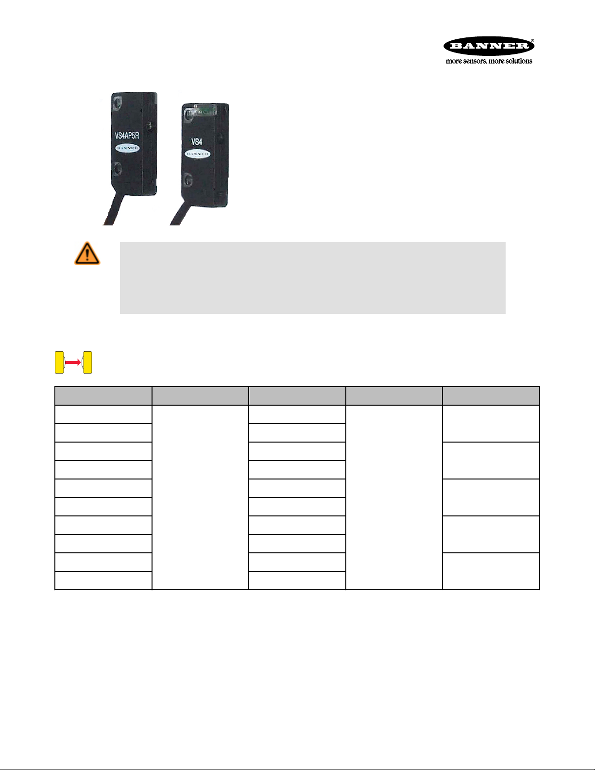
VS4 Series Opposed-Mode Sensors
Miniature Self-Contained Sensors
• Totally self-contained miniature sensors
• 10 to 30V dc operation
• Visible red sensing beam, 660 nm
• Up to 1.0 m (39 in) sensing range
• Choose dark or light operate models
• Choose models with NPN (sinking) or PNP (sourcing) output
• 2-wire and 3-wire hookup; output load capacity to 50 mA
• Choice of integral cable or quick-disconnect pigtail
WARNING: Not To Be Used for Personnel Protection
Never use this device as a sensing device for personnel protection. Doing so could lead to serious
injury or death. This device does NOT include the self-checking redundant circuitry necessary to allow its
use in personnel safety applications. A sensor failure or malfunction can cause either an energized or deenergized sensor output condition.
Models
Model Number Sensing Range Cable Supply Voltage Output Type
VS4EV
VS4EVQ 3-pin pico Pigtail QD
VS4AN5R 2 m (6.5 ft) 3 wire
VS4AN5RQ 3-pin pico Pigtail QD
VS4RN5R 2 m (6.5 ft) 3 wire
1.0 m (39 in)
VS4RN5RQ 3-pin pico Pigtail QD
VS4AP5R 2 m (6.5 ft) 3 wire
VS4AP5RQ 3-pin pico Pigtail QD
VS4RP5R 2 m (6.5 ft) 3 wire
VS4RP5RQ 3-pin pico Pigtail QD
2 m (6.5 ft) 2 wire
10 to 30V dc
–
NPN/LO
NPN/DO
PNP/LO
PNP/DO
Specifications
Supply Voltage and Current
10 to 30V dc (10% maximum ripple)
Emitter: 25 mA
Receiver: 25 mA (exclusive of load)
Supply Protection Circuitry
Protected against reverse polarity and transient voltages
P/N 69421_web
Rev. C
Indicators
Two LEDs: Green and Yellow
Green ON steady: power to sensor is ON
Green flashing: output overload
Yellow ON steady: light is sensed
Yellow flashing: marginal excess gain (1 to 1.5x) in
light condition
2/18/2013
Page 2
1
10
100
0.10 m
4 in
1.0 m
40 in
10.0 m
400 in
0.01 m
0.4 in
E
X
C
E
S
S
G
A
I
N
DISTANCE
1000
1000 mm
40 in
800 mm
32 in
600 mm
24 in
400 mm
16 in
200 mm
8 in
0
0
-20 mm
-40 mm
-60 mm
20 mm
40 mm
60 mm
0
DISTANCE
2.36 in
-2.36 in
1.57 in
-1.57 in
0.78 in
-0.78 in
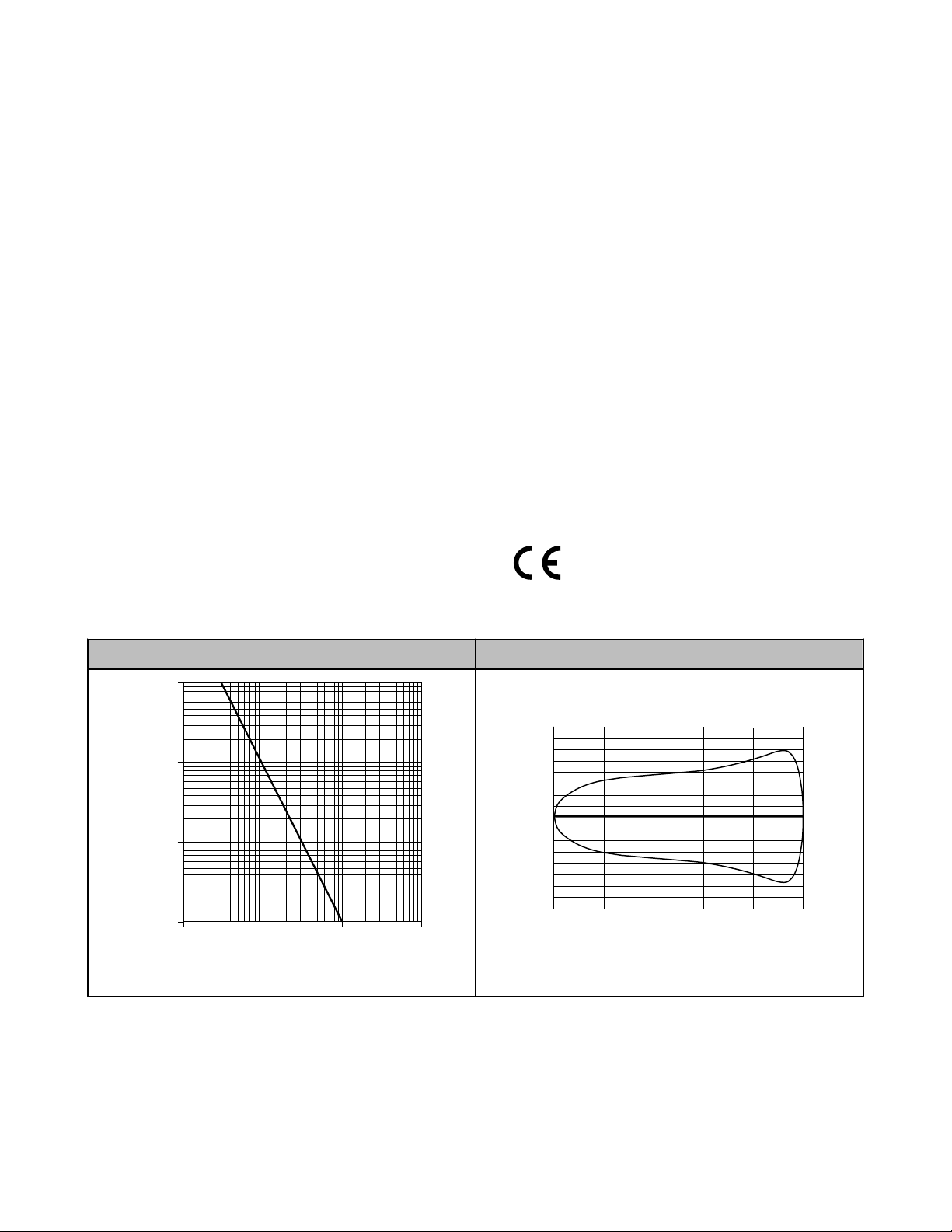
Effective Beam =3 mm
BEAM PATTERN WIDTH
VS4 Series Opposed-Mode Sensors
Output Configuration
SPST solid-state switch
Choose NPN (current sinking) or PNP (current sourc-
ing), depending on model
Choose light operate (N.O.) or dark operate (N.C.), de-
pending on model
Output Rating
50 mA maximum
Off-state leakage current: < 1 microamp at 24V dc
On-state saturation voltage: < 0.25V at 10 mA dc; <
0.5V at 50 mA dc
Output Protection Circuitry
Protected against false pulse on power-up ‑and continuous overload or short circuit of outputs
Overload trip point ≥ 100 mA
Output Response Time
1 millisecond ON and 0.5 milliseconds OFF
NOTE: 100 millisecond delay on power-up: output is
non-conducting during this time
Repeatability
100 microseconds
Environmental Rating
IP67; NEMA 6
Construction
Polycarbonate mounting holes and lens
Low pressure molded thermoplastic housing (UL 94-
V0)
Connections
2 m (6.5 ft) attached cable: three #28 ga stranded conductors with PE insulation; PVC outer cable jacket; or
3-pin Pico-style pigtail quick-disconnect fitting. QD cables are ordered separately.
Operating Conditions
Temperature: −20° to +55° C (−4° to +131°F)
Humidity: 80% at +50° C (non-condensing)
Vibration and Mechanical Shock
Vibration: All models meet IEC 60068-2-6, IEC
60947-5-2, UL491 Section 40, MIL-STD-202F Method
201A; 10 to 60 Hz, 0.5 mm peak to peak
Shock: All models meet IEC 60068-2-27, IEC
60947-5-2; 30g peak acceleration, 11 millisecond pulse
duration, half-sine wave pulse shape
Application Notes
M2 stainless steel mounting hardware included. Optional mounting bracket available.
Certifications
Performance Curves
Excess Gain Beam Pattern
Rev. C
2 www.bannerengineering.com - tel: 763-544-3164 P/N 69421_web
Page 3

8.25 mm
(0.32")
16.0 mm (0.63")
2x ø2.4 mm
(ø0.09")
9.8 mm (0.37")
3.1 mm (0.12")
25.4 mm
(1.00")
4.75 mm
(0.19")
Emitter
2.75 mm (0.11")
Receiver
2.75 mm (0.11")
12.5 mm (0.49")
10-30V dc
+
–
bu
bn
10-30V dc
–
+
bn
bu
bk
Load
10-30V dc
–
+
bn
bu
bk
Load
10-30V dc
+
–
bu
bn
bk
10-30V dc
–
+
bn
bu
bk
Load
10-30V dc
–
+
bn
bu
bk
Load
ø 9.5
35 Typ.
M8 x 1
4
3
1
VS4 Series Opposed-Mode Sensors
Dimensions
Hookups
Emitters with Cable
Emitters with Quick-Disconnect
NPN Models with Cable
NPN Models with Quick-Disconnect
PNP Models with Cable
PNP Models with Quick-Disconnect
Accessories
Quick-Disconnect Cables
3-Pin Threaded M8/Pico-Style Cordsets
Model Length Style Dimensions Pinout
PKG3M-2 2.00 m (6.56 ft) Straight
PKG3M-5 5.00 m (16.40 ft)
PKG3M-7 7.00 m (22.97 ft)
PKG3M-9 9.00 m (29.53 ft)
PKG3M-10 10.0 m (32.81 ft)
1 = Brown
3 = Blue
4 = Black
P/N 69421_web
Rev. C
www.bannerengineering.com - tel: 763-544-3164 3
Page 4

2 x ø 1.5 mm
(0.06 in)
2 x ø 0.5 mm
(0.02 in)
2 x 20.0 mm
(0.80 in)
2.0 mm
(0.08 in)
12.0 mm
(0.47 in)
4 x 1.9 mm
(0.08 in)
2 x 2.85 mm
(0.11 in)
2 x 5.55 mm
(0.22 in)
2 x 5.55 mm
(0.22 in)
4 x ø 2.1 mm
(0.08 in)
2 x 5.1 mm
(0.20 in)
2.0 mm
(0.08 in)
16.0 mm
(0.63 in)
2.9 mm
(0.11 in)
2.9 mm
(0.11 in)
12.40 mm
(0.49 in)
5.0 mm
(0.20 in)
2 x ø 2.0 mm
(0.08 in)
2 x ø 1.0 mm
(0.04 in)
2 x 20.0 mm
(0.80 in)
2.0 mm
(0.08 in)
12.0 mm
(0.47 in)
4 x 1.9 mm
(0.08 in)
2 x 2.85 mm
(0.11 in)
2 x 5.55 mm
(0.22 in)
2 x 5.55 mm
(0.22 in)
4 x ø 2.1 mm
(0.08 in)
2 x 5.1 mm
(0.20 in)
2.0 mm
(0.08 in)
16.0 mm
(0.63 in)
2.9 mm
(0.11 in)
2.9 mm
(0.11 in)
12.40 mm
(0.49 in)
5.0mm
(0.20 in)
33
17
11
C
B
A
VS4 Series Opposed-Mode Sensors
Apertures
Model Description Dimensions
APVS4-0206
APVS4-0408
• 2-holed aperture
• 0.020 in and 0.060 in diameter holes
• 2-holed aperture
• 0.040 in and 0.080 in diameter holes
Brackets
SMBVS4SRA
• Right-angle bracket
• 300 series stainless steel
A = 3 x R1.6, B = ø 3.2,
C = R1.2
Banner Engineering Corp Limited Warranty
Banner Engineering Corp. warrants its products to be free from defects in material and workmanship for one year following the date of
shipment. Banner Engineering Corp. will repair or replace, free of charge, any product of its manufacture which, at the time it is returned
to the factory, is found to have been defective during the warranty period. This warranty does not cover damage or liability for misuse,
abuse, or the improper application or installation of the Banner product.
THIS LIMITED WARRANTY IS EXCLUSIVE AND IN LIEU OF ALL OTHER WARRANTIES WHETHER EXPRESS OR IMPLIED (INCLUDING, WITHOUT LIMITATION, ANY WARRANTY OF MERCHANTABILITY OR FITNESS FOR A PARTICULAR PURPOSE), AND
WHETHER ARISING UNDER COURSE OF PERFORMANCE, COURSE OF DEALING OR TRADE USAGE.
This Warranty is exclusive and limited to repair or, at the discretion of Banner Engineering Corp., replacement. IN NO EVENT SHALL
BANNER ENGINEERING CORP. BE LIABLE TO BUYER OR ANY OTHER PERSON OR ENTITY FOR ANY EXTRA COSTS, EXPENSES, LOSSES, LOSS OF PROFITS, OR ANY INCIDENTAL, CONSEQUENTIAL OR SPECIAL DAMAGES RESULTING FROM ANY
PRODUCT DEFECT OR FROM THE USE OR INABILITY TO USE THE PRODUCT, WHETHER ARISING IN CONTRACT OR WARRANTY, STATUTE, TORT, STRICT LIABILITY, NEGLIGENCE, OR OTHERWISE.
Banner Engineering Corp. reserves the right to change, modify or improve the design of the product without assuming any obligations or
liabilities relating to any product previously manufactured by Banner Engineering Corp.
 Loading...